SDBR48 - Fridge Perlick - Free user manual and instructions
Find the device manual for free SDBR48 Perlick in PDF.

User questions about SDBR48 Perlick
0 question about this device. Answer the ones you know or ask your own.
Ask a new question about this device
Download the instructions for your Fridge in PDF format for free! Find your manual SDBR48 - Perlick and take your electronic device back in hand. On this page are published all the documents necessary for the use of your device. SDBR48 by Perlick.
USER MANUAL SDBR48 Perlick
Installation & Operation Manual
Commercial Back Bar
- Remote & Self-Contained Standard height and low height Models BBR, BBS, BBRLP & BBSLP Series
- Remote & Self-Contained Narrow Door Models BBRN & BBRSN Series
- Remote & Self-Contained Pass Thru Models PTR & PTS Series
- Remote & Self-Contained Sliding Door Models SDB & SDP Series
• Self-Contained Dual-Zone DZS Series Concessionaire - Direct Draw DDC & DDS Series
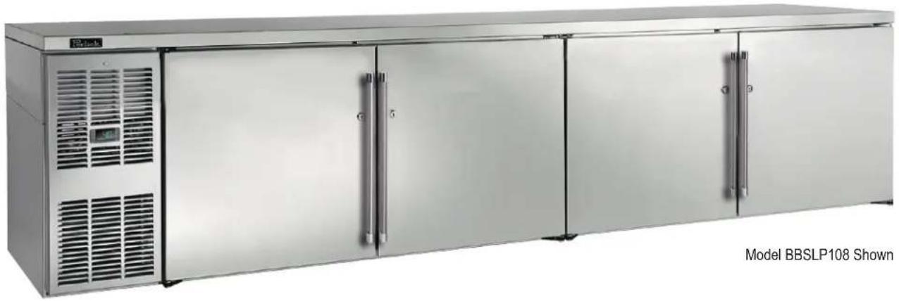
natural_image
Exterior view of a stainless steel BBSLP 108 refrigerated stainless steel kitchen unit (no signage or text on cabinet)


The Perlick Corporation verifies this product does not contain a prohibited refrigerant as defined by the California Air Resource Board (CARB), the state of New York, and any other state with HFC prohibition laws. This product does not contain HFC's. The following disclosure statement is provided to comply with the CARB regulation:
This equipment is prohibited from use in California with any refrigerants on the "List Of Prohibited Substances" for that specific end use, in accordance with the California Code of Regulations, title 17, section 95374. This disclosure statement has been reviewed and approved by the Perlick Corporation and the Perlick Corporation attests under penalty of perjury, that these statements are true and accurate.
Form No. Z2604
Rev A 04.20.23
TABLE OF CONTENTS
General Information....2
Safety 2
Prior To Installation....3
Installation 4
Operation....5
Adjustments....7
Maintenance....11
Troubleshooting....14
Dimensions.... 16
Wiring Diagrams 34
Warranty 48
GENERAL INFORMATION
Introduction
Congratulations on your purchase of a Perlick commercial back bar product. This manual has been prepared to assist you in the installation of your cabinet and to acquaint you with its operation and maintenance.
We dedicate considerable time to ensure that our products provide the highest level of customer satisfaction. If service is required, your dealer can provide you with a list of qualified service agents. For your own protection, never return merchandise for credit without our approval.
We thank you for selecting a Perlick product and assure you of our continuing interest in your satisfaction.
Warranty
To register your product, visit our web site at www.perlick.com. Click on “Commercial”, then “Service”. Click on the link “Warranty Registration Form”. You must complete and submit this form or the installation date will revert back to the ship date.
Please record the purchase date and the dealer's name, address and telephone number below.
Model Number: ____
Serial Number: ____
Purchase Date: ____
Dealer Name & Address
Phone Number
SAFETY
PLEASE READ all instructions completely before attempting to install or operate the unit. Take particular note of the DANGER, WARNING and CAUTION information in the manual. The information is important for the safe and efficient installation, operation and care of your Perlick unit.
A DANGER Indicates a hazard that WILL result in serious injury or death if precautions are not followed.
WARNING Indicates a hazard MAY cause serious injury or death if precautions are not followed.
A CAUTION Indicates a hazard where minor or moderate injury may occur if precautions are not followed.
NOTICE Indicates that property damage may occur if warnings or instructions are not followed.
IMPORTANT!
Read and understand all information in this manual before attempting the installation.
All plumbing and electrical work must be performed by a qualified technician and conform to all applicable state and local codes.
! WARNING: California Prop 65 Notice
These products may expose you to chemicals including Chromium, which are known to the state of California to cause cancer and birth defects or other reproductive harm. For more information on whether a product in this list contains these chemicals, please refer to the specific product page at perlick.com. Or to find out more about Prop 65, go to P65Warnings.ca.gov.
PRIOR TO INSTALLATION
Uncrating and Inspection
Remove all crating material. Carefully inspect cabinet for hidden damage. If damage is discovered, file your claim immediately with the transport company. Perlick is not responsible for damage in transit.
WARNING
Take caution when handling, moving and using the product to avoid damaging the refrigerant tubing or increasing the risk of a leak.
DANGER
All service work shall be performed by factory authorized service personnel and all component parts shall be replaced with like components to minimize the risk of possible ignition due to incorrect parts or improper service.
CAUTION
If service is necessary, repair work must be performed by a Perlick authorized servicer. Work done by unqualified individuals could potentially be dangerous and will void the warranty.
CAUTION
Do not cut cardboard sleeve covering the unit. Cutting may result in damage to the exterior of the cabinet. Failure to follow this procedure may damage the compressor and void warranty.
- Uncrate the unit on flat, level surface. Remove the cardboard sleeve by removing the banding securing the sleeve to the shipping base. Carefully lift the cardboard sleeve up over the top of the unit.
- Carefully lift unit off the base and onto a hand truck or dolly. Make sure unit is balanced on transporting device using soft, flexible strapping. Protect unit surfaces with cloth material where strapping contacts unit.
CAUTION
Do not lift unit by drawer, shelving or door handles or damage to the unit could occur.
WARNING
To prevent personal injury, two people minimum required to lift the unit. Larger units may require additional personnel.
-
Before moving unit, secure door(s) to unit with tape to prevent from opening.
-
Carefully move unit to installation site and place in front of opening.
CAUTION
Finished flooring should be protected with appropriate material to avoid damage from moving the unit.
Plumbing
CAUTION
Do not over-tighten drain fitting or damage to the threads could occur.
Plumbing
Self-Contained
Condensate from the cooling coil is automatically evaporated from the condensate pan located in the condensing unit housing on self-contained models.
Self-Contained & Remote
Each unit is equipped with a floor drain located in the right rear corner of the cabinet. The drain can be plumbed to an external floor drain by connecting to the 3/4" NPT thread connection on the side, or the 1" NPS thread connection out the bottom, of the unit. Both drain ports come plugged from the factory and can be removed if needed.
Remotes
Dispensing head drainers should be plumbed to a dump tank or floor drain. Always rinse drainer with sufficient amounts of water daily to prevent drain from clogging.
Remote evaporator condensate plumbing should be routed out on of the cabinet side access holes or to one of the floor drains and should always be sloped to the drain with no rise to prevent drainage. A trap should be used, however, trap peak must be below condensate drain pan nipple.
Electrical
The cabinet must be connected to a separately fused power source (see Electrical Specification Plate affixed to unit) in accordance with National and Local electrical codes.
Self-contained Perlick units come equipped with a NEMA 5-15P 90° plug with an 6'5" cord extending beyond the rear of the cabinet. The electrical outlet must be flush with, or recessed into, the wall surface.
NOTE: Never use an extension cord to extend the power cord to the electrical receptacle.
CAUTION
If unit has been laid on its back or sides, place unit upright and allow
minimum of 24 hours before connecting power. Failure to follow this procedure may damage the compressor and void the warranty.
CAUTION
Do not attempt to operate the equipment on any other power source than
that listed on the Electrical Specification Plate attached to the unit.
DANGER
ELECTROCUTION HAZARD! Electrical grounding is
required. Appliances furnished with a 3-prong (grounding) polarized plug are equipped for your protection against possible shock hazards.
- Never remove the round grounding prong
from the plug.
- Never use a 2-prong adapter.
- Never use extension cord to connect power to the unit.
- If a 2-prong receptacle is encountered, or a longer power cord is required, contact a qualified electrician to have it replaced in accordance with applicable electrical codes.
DANGER
Failure to comply with these electrical guidelines may
result in possible death or serious injury, fire, or loss of property.
NOTICE
This product contains blown foam insulation
using blowing agent R-611 (Methyl Formate). The foam in this product does not contain HFC's, CFC's, or HCFC's.
INSTALLATION
General Information
- For units equipped with a power cord, the cord and plug may be aligned with a recess in the back panel to allow the unit to be pushed closer to the wall. For correct alignment, the wall outlet must be located 4" - 10" above the floor.
• Floor must be level in area of installation.
Preparing the Space
CAUTION
Make sure the floor under the unit is level with the
surrounding finished floor. Protect a finished floor with plywood, cardboard or some other suitable material before moving the unit into place. Failure to do this may result in damage to the floor.
NOTE: If unit has been laid on its back or sides, place unit upright and allow minimum of 24 hours before connecting to a power source. Failure to follow this procedure may damage the compressor and void warranty.
- Make sure the space opening is correctly sized for the unit. See Dimension drawings at the back of this manual for correct dimensions.
NOTE: For a cabinet door to open properly, the door must open a minimum of 90^ . Use a minimum 3" filler in corner installations to assure a 90^ opening. Allow 24" clearance in front of the unit for full door swing and shelf/drawer pull-out.
-
Check that the following are level and square:
-
Front and interior opening
• Installation opening and floor surface
NOTE: The floor under the unit must be at the same level as the surrounding finished floor.
Casters or Legs
Refer to the instructions included with the Casters or Legs Kit.
Installing the Unit
CAUTION
If unit has been laid on its back or sides, place unit
upright and allow minimum of 24 hours before connecting power.
- With power applied to the unit, check that the lighting and cooling functions operate properly, then turn off power to the wall outlet and/or circuit breaker.
- Position the cabinet into place using rollers when necessary.
NOTE: Proper air flow around the condensing unit is necessary for efficient operation. Never obstruct the air flow in and out of the condensing unit.
-
When cabinet is in place, check installation with carpenter's level. When the unit is level front-to-back and side-to-side, accumulated water will drain out of cabinet to evaporator drain.
-
Turn on power to the outlet and/or circuit breaker.
WOOD OVERLAY INSTALLATION
Before beginning installation, check all components for proper fit and finish. Handle should be installed to the overlay prior to installing overlay to door (use countersunk flathead fasteners for handle installation.)
CAUTION For best performance and functionality, the overlay panels should be 3/4" thick. The weight of the overlays should not exceed 20 lbs for solid (-2) doors, 10 lbs for glass (-4) doors, or 10 lbs for drawer (-6) models.
- -2, -4 and -6 models come ready to accept wood overlay as shown below.

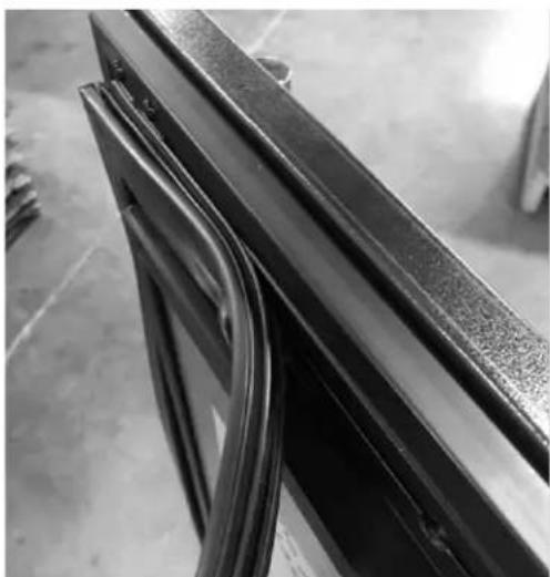
natural_image
Exterior view of a rectangular industrial box with black frame and white interior (no visible text or symbols)- Remove the gasket carefully starting at the corners and avoid ripping the dart.
natural_image
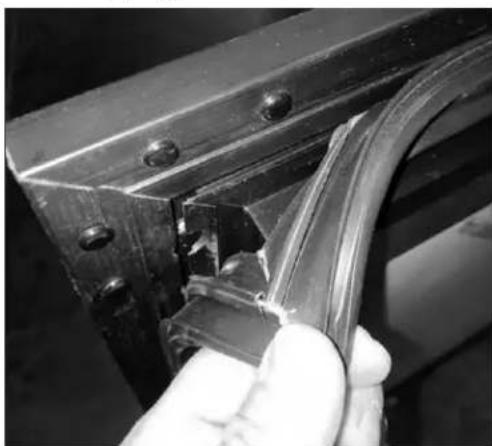
Close-up of a hand holding a metallic bracket with a crack, no visible text or symbols- In some cases, the dart on the gasket may rip. If this happens, replace with a new gasket.

natural_image
Close-up of a mechanical component with visible cracks and a circular opening (no text or symbols)- With the gasket removed, the screw holes needed to hold the overlay panel will be reveal as shown below.
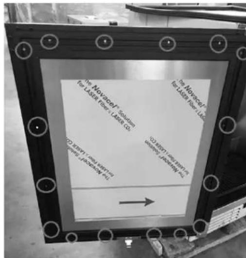
text_image
The Novacel® Solution for LASER Fiber + LASER CO The Novacel® for LASER Fiber Llc for LASER Fiber Llc The Novacel® for LASER Fiber Llc for LASER Fiber Llc the Novacel® for LASER Fiber Llc the Novacel® for LASER Fiber Llc the Novacel® for LASER Fiber Llc the Novacel® for LASER Fiber Llc the Novacel® for LASER Fiber Llc the Novacel® for LASER Fiber Llc the Novacel® for LASER Fiber Llc the Novacel® for LASER Fiber Llc to the Novacel® for LASER Fiber Llc to the Novacel® for LASER Fiber Llc to the Novacel® for LASER Fiber Llc to the Novacel® for LASER Fiber Llc to the Novacel® for LASER Fiber Llc to the Novacel® for LASER Fiber Llc to the Novacel® for LASER Fiber Llc to the Novocel® for LASER Fiber Llc to the Novocel® for LASER Fiber Llc to the Novocel® for LASER Fiber Llc to the Novocel® for LASER Fiber Llc to the Novocel® for LASER Fiber Llc to the Novocel® for LASER Fiber Llc to the Novocel®- Loosely attached the four corners of the overlay panel with the door frame with #10 x 3/4" wood screws.
text_image
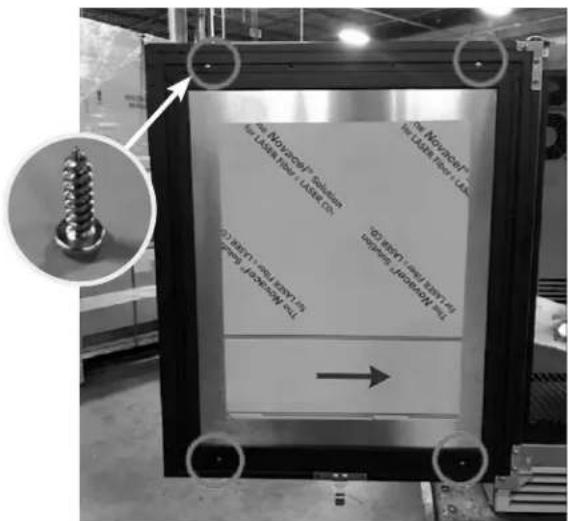
The Notozocyl® Solution the LAIN timer / LAIN C# The Notozocyl® the LAIN timer / LAIN C# (1) BRY1 (the BRY2) (2) BRY1 (the BRY3) (3) BRY1 (the BRY4) (4) BRY1 (the BRY5) →- After alignment is satisfied, fasten down all screws through the screw holes.

text_image
The Nomine/10000000000 In Laser Film + Laser Co. No Nomine/10000000000 In Laser Film + Laser Co. C250-10000000000 In laser 10000000000 C250-1000000000 In laser 1000000000 →- Make sure the overlay panel is aligned properly with the door.

natural_image
Black rectangular industrial cabinet placed on a pallet in a warehouse (no visible text or symbols)⚠ CAUTION Do not overtighten wood overlay attachment screws, as this may damage the factory supplied door frame.
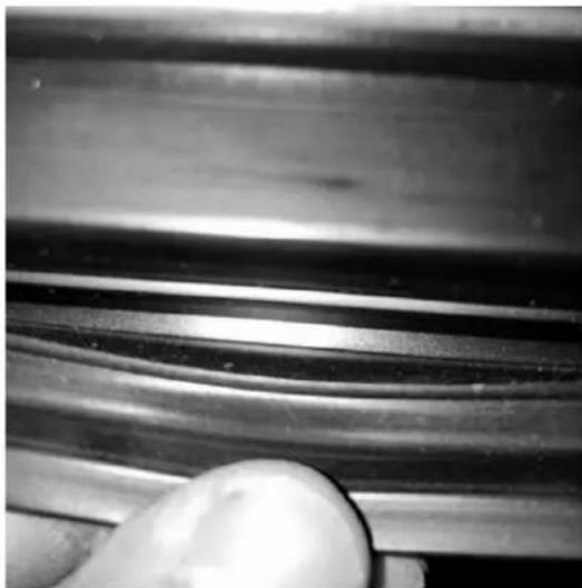
- When re-installing the gasket, make sure the dart is pressed inside the slot on the door frame. Start at the four corners and firmly press your way inwards
natural_image
Close-up of a metal bracket with visible wear and cutouts, no text or symbols present- Verify that the gasket is fully seated onto the door frame when completed.
natural_image
Close-up of a metallic mechanical component with smooth curved grooves and a hand holding a white ball (no text or symbols visible)- After installation of the overlay panel is completed, verify that the gasket is completely sealing around the cabinet frame. If installing panels onto drawer models (-6), repeat installation process for second drawer face. Installation is now complete.

text_image
Siber 8 2014®WINE RACK TRIM (OPTIONAL)
All wine reserve racks come with sleek stainless steel fronts. Unfinished solid hardwood fronts are optional and can be removed and replaced with other wood to match your cabinetry. See diagrams below for wine rack face details.
NOTE: The unfinished faces should be finished and sealed. In many cases, stains and/or finishes have odors that may be objectionable in an enclosed area. Do not stain or finish wood faces while installed on unit. To remove the front wood face from the wine shelf, simply pull out the wine shelf and remove the fasteners, finish as desired, and when completely dry, reinstall with fasteners.
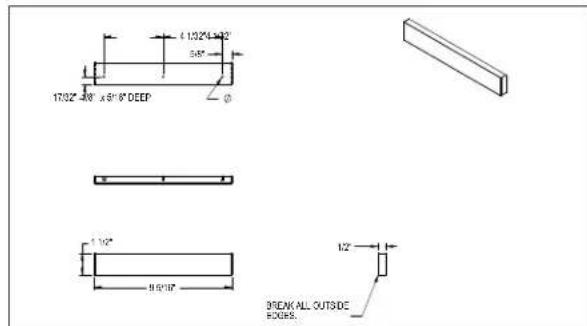
text_image
1732°-40' x 9'16" DEEP 1/32" 9.5'17" 1/2" BREAK ALL OUTSIDE HOURS.Wine Rack Trim, 15" models

text_image
±170° 0-150° ±516 DECP14° 50° 58° 710° 1170° 170° 516° 112° 15516° 1/2" BREAK ALL OUTSIDE EDGE3Wine Rack Trim, 24" models
Electric Condensate Evapaway (Optional)
For installation in areas of high humidity, a 115-volt electric condensate pan can be installed underneath the cabinet to collect and evaporate the condensate from the cabinet evaporator. A 6'3-prong plug is included. A separate circuit should be provided for the heater. The kit can be used only on cabinets equipped with 4" minimum legs; it cannot be used on units equipped with platform or base plate kits. Follow instructions supplied with the kit.
Base Plate Installation (Optional)
Once the unit is secured in place, install the base plate brackets to the cabinet bottom in the holes provided. Attach base plate to brackets. Refer to the installation instructions included with the Base Plate Kit.
Sealing Cabinet to Floor
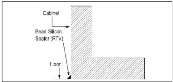
For installation of a cabinet directly to the floor, (without legs or casters), the cabinet must be sealed to the floor to prevent liquid spillage passing under inaccessible portions of the equipment and to maintain the equipments NSF sanitation certification. The floor surface shall be level and smooth. It is recommended to be sealed to the floor using an NSF certified silicone sealer. (Figure 1).
text_image
Cabinet Bead Silicon Sealer (RTV) FloorFigure 1: Sealing Cabinet to Floor
Faucet and Dispensing Head Installation
Refer to the instructions included with the Faucet and Dispensing Head Kit.
OPERATION
Refrigeration and Temperature Control (Non-DZS Models)
The cabinet is equipped with a heavy-duty refrigeration system designed to automatically maintain a storage temperature of approximately 36^ F.
Allow a minimum of 24 hours for ambient temperature product to reach storage temperature.
Draft beer should be stored at a temperature between 32^-38^ F. The most common cause of dispensing problems is improper temperature; beer will foam at warmer temperatures.
Refrigeration and Temperature Control (DZS)
The unit is equipped with a heavy-duty, digitally controlled, dual-zone refrigeration system designed for two separate compartments.
The temperature controls have been factory set according to customer specifications based on intended use. The digital controller on the left controls the compartment on the left side and the digital controller on the right controls the compartment on the right side.
• Factory temperature settings:
Approximately 36^ F for refrigerator, 45^ F for white wine storage (compartment closest to the condensing unit/refrigeration module), and 60^ F for red wine storage. Adjustable range is 34^ F - 42^ F for the refrigerator and 40^ F - 60^ F for wine.
- Coldest compartment must always be the compartment closest to the condensing unit/refrigeration module.
- Minimum temperature difference between two compartments is 10^ F. Maximum temperature difference between the two compartments is 30^ F for the DZS60 Model and 20^ F for the DZS36 Model.
- The unit is not intended for temperature settings outside the parameters mentioned above. Attempts to deviate from the specified temperature parameters may result in unsatisfactory serving temperatures.
Allow a minimum of 24 hours for ambient temperature product to reach storage temperature.
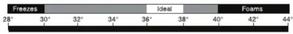
Beer will freeze at temperatures lower than 30^ F. When beer freezes, the alcohol in the beer may separate and cause the beer to be cloudy with an “off” taste.
The following chart shows how temperature affects beer:
text_image
Freezes 28° 30° 32° 34° 36° 38° 40° 42° 44° Ideal FoamsChecking Product Temperature
- To accurately check the temperature of product stored in the refrigerated compartment, insert an accurate thermometer into a plastic unbreakable bottle, partially filled with water. Tighten bottle cap securely.
- Place the bottle in the desired area for 24 hours. Refrain from opening the unit during the testing period. After 24 hours, check the temperature of the water. Adjust the temperature accordingly using the procedures on this page.
The following factors affect the internal temperature of the unit:
• Temperature setting
• Room temperature where installed
• Number of times the door is opened and closed
• Length of time door is left open
• Style of door installed
• Door gasket seal and condition
- Amount of time the internal light is illuminated
• Installation in direct sunlight or near a heat source
Interior Light (Not applicable to all models)
The unit is equipped with an interior LED light in the upper front of the unit just inside the door or drawer. The light illuminates when the manual rocker light switch is turned on. The rocker light switch is located behind the LED light on the inside of the frame on either the right or left side (same side as the compressor).
Digital Temperature Control
To Adjust the Temperature Set Point (Figure 2):
- Press the set button. The label "SET" will be displayed.
- Press the set button a second time. The set point will be displayed.
- To change the Set point value, press the or keys within 15 seconds.
- Press set to confirm the new setpoint value.
- After 10 seconds the display will return to indicating the cabinet temperature.

text_image
-8.80(°C) -8.80(AUX °C) SETFigure 2: Digital Temperature Controller
ADJUSTMENTS
Changing Door Swing Direction
NOTE: Changing the door swing direction is not advisable if the door is not equipped with a full length handle. Doing so may result in an undesirable handle position..
Hinge Kits
Part No. 67439R: Right Hinging
Part No. 67439L: Left Hinging
Tools Required
• Large flat head screwdriver
• Regular Phillips head screwdriver
• Hinge Kit from Perlick
- Plastic putty knife
Procedure
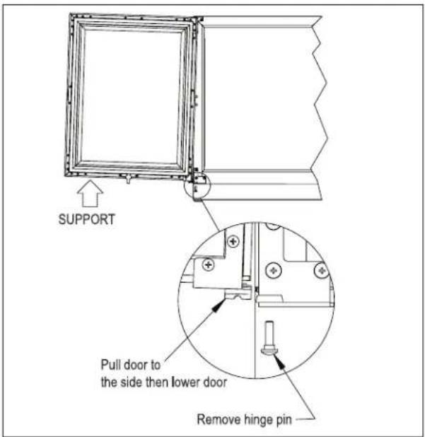
- Support the door in the open position as shown in Figure 3. Remove the hinge pin.
text_image
SUPPORT Pull door to the side then lower door Remove hinge pinFigure 3: Door Removal
- Pull door to the side and then lower the door.
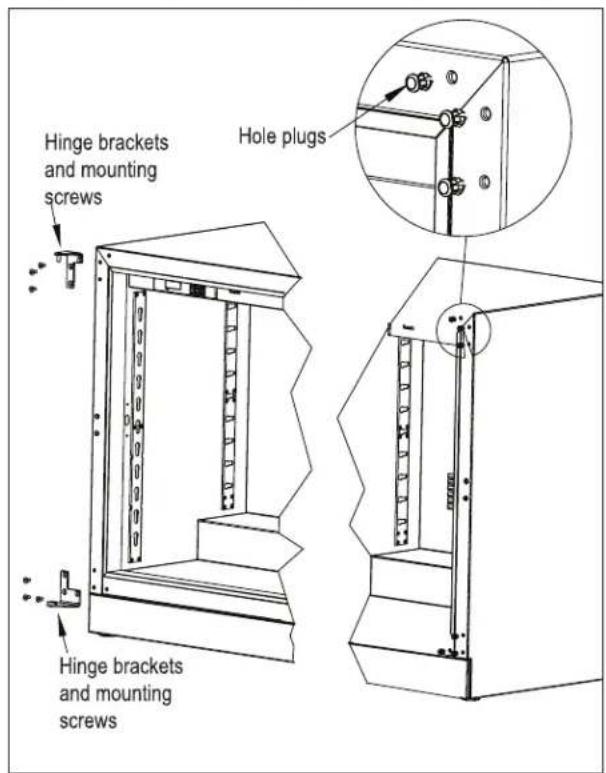
- Remove top and bottom hinge brackets. Retain screws for later use. See Figure 4.
- Remove the hole plugs from the top and bottom hinge bracket mounting holes (Figure 4). Place the plug in the holes on the opposite side made vacant by removing the hinges in step 3.
text_image
Hinge brackets and mounting screws Hinge brackets and mounting screws Hole plugsFigure 4: Hinge Removal
- Using the screws removed in step 3, install the top and bottom hinge brackets from kit (Figure 5).

text_image
Hinge brackets and mounting screws Hinge brackets and mounting screwsFigure 5: Hinge Installation
- Remove the top and bottom hinge brackets from the door (Figure 6). Retain the screws for later use.

text_image
Hinge brackets and mounting screwsFigure 6: Door Brackets
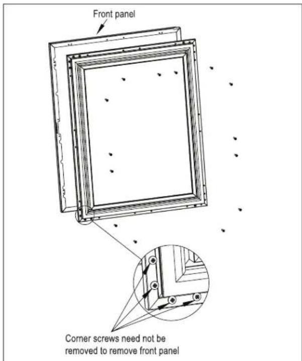
- Remove the front panel from the door assembly by removing the inner mounting screws, 4 per side, from the perimeter of the door assembly (Figure 7). Rotate the front panel 180°. The top becomes the bottom. Reattach using the same screws and mounting holes.
text_image
Front panel Corner screws need not be removed to remove front panelFigure 7: Removing Front Panel
- Insert bearing into door top hinge bracket (Figure 8).
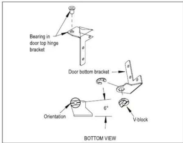
text_image
Bearing in door top hinge bracket Door bottom bracket Orientation 6° V-block BOTTOM VIEWFigure 8: Bearing and V-Block
-
Insert V-block into door bottom hinge bracket and attach with e-clip (Figure 8). Note the orientation of the V-block.
-
Attach the top and bottom door hinges using screws removed in step 6 (Figure 9).

text_image
Top hinge and screws Bottom hinge and screwsFigure 9: Door Hinges
- Place lower V-block into lower cabinet hinge with notch parallel to cabinet (Figure 10).

text_image
V-block parallel to cabinet TOP VIEWFigure 10: Installing V-Block
- Lift door assembly and insert top pin into bearing. Move door toward cabinet and align V-blocks (Figure 11).

text_image
Insert top pin into bearing Insert and tighten hinge pinFigure 11: Installing Door
- Insert and tighten lower hinge pin to complete assembly.
Shelving Adjustment
See Figure 12.
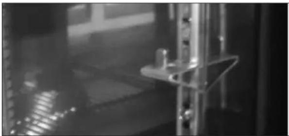
natural_image
Interior view of a dimly lit industrial or laboratory facility with metal fixtures and reflective surfaces (no visible text or symbols)Figure 12: Shelf Bracket
CAUTION
Completely empty shelf or drawer before removing.
- Open the door. Tilt the shelf and remove it from the unit
- Reposition each bracket separately. Grasp the middle of the bracket, pull the front end up and out, then forward to remove it.
- Place brackets at desired location and reinstall shelf(s)
Drawer Dividers Adjustment
See Figure 13.
CAUTION
Completely empty shelf or drawer before removing.
Lift divider straight up and move to desired position, engaging tabs in holes. Make sure divider tabs engage corresponding holes on both sides.
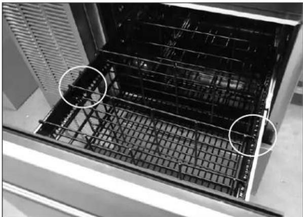
natural_image
Interior view of a stainless steel oven with visible grating and two circled areas of interest (no text or symbols)Figure 13: Drawer Divider Adjustment
Sliding Doors
Removing/Installing
- To remove the sliding door, simply grasp the door on each side and lift up off the bottom track, then tilt outwards and pull down to remove from the upper track.
- To reinstall sliding door, place door in upper track making sure to engage the bracket (Figure 4), lift door up into the track and place into the bottom track.

text_image
Make sure door engages bracketFigure 14: Removing/Installing Sliding Door
Adjusting Door Spring Tension
A tension spring is located in the upper track of each door. To increase or decrease spring tension, remove the Phillips screw and position the bracket in one of three detentes and reinstall screw. The detente farthest to the left creates the least amount of tension.
NOTE: Units are shipped from the factory with springs set at the weakest settings.
Sliding Door Lock
Each set of sliding doors is equipped with a keyed lock located on the bottom of the right side door. To lock the doors, place the lock lever in the "DOWN" position and lock with the key. Unlock with the key and place the lever in the "UP" position to open.
MAINTENANCE

Never attempt to repair or perform maintenance on
the unit until the main electrical power to the unit has been disconnected!

Take caution when handling, moving and using the
product to avoid damaging the refrigerant tubing or increasing the risk of a leak.
LED Light Replacement
See Figure 15.
- Open the door, or remove the upper drawer (see Removing Drawer, Figure 16).
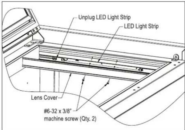
text_image
Unplug LED Light Strip LED Light Strip Lens Cover #6-32 x 3/8" machine screw (Qty. 2)Figure 15: Interior LED Light
- Using a flat blade screwdriver, carefully pry off the lens cover.

text_image
Push latch forward and pull front of latch up to release; push down and slide back to lock When reinstalling, make sure wheel engages slotFigure 16: Removing/Installing Drawer
-
Remove the two screws securing LED light to housing.
-
Unplug the LED from the wiring harness.
- Plug new LED into harness and secure to housing using screws removed in step 2.
- Snap LED cover into place.
Cleaning/Lubricating Drawer Extenders
Drawer must be removed to clean or lubricate the extenders. Use a food grade lubricant to lubricate the drawer extenders.
Removing Drawer
See Figure 15.
CAUTION
Completely empty drawer before removing.
- Pull the drawer out to its furthest position. Locate the latch in the middle of both extenders. Push each latch forward and lift front of latch up (unlocked position), then lift the front of the drawer and pull out.
Installing Drawer
- Place drawer on to the extenders, making sure wheels engage the slots on each side.
- Push drawer all the way in, then pull drawer out and push the latch down and back to engage. Make sure front of latches are fully down and back, engaging the extenders.
Stainless Steel Care & Cleaning
General
Contrary to popular belief, stainless steel is susceptible to rusting. Corrosion on metals is everywhere. It is recognized quickly on iron and steel as unsightly yellow/orange rust. Such metals are called “active” because they actively corrode in a natural environment when their atoms combine with oxygen.
Stainless steel is a “passive” metal because it contains other metals like chromium, nickel and manganese that stabilize the atoms. Chromium provides an invisible passive film that covers the steel surface acting as a shield against corrosion. As long as the film is intact and not contaminated, the metal is passive and stainless. If the passive film of stainless steel has been broken, equipment starts to corrode and rust.
There are three basic things which can break down stainless steel's passive layer and allow corrosion to occur:
- Mechanical abrasion
- Deposits and water
- Chlorides
Mechanical abrasion refers to the things that will scratch a steel surface. Steel pads, wire brushes and scrapers are prime examples.
Water comes out of the faucet in varying degrees of hardness. Depending on what part of the country you live in, you may have hard or soft water. Hard water may leave spots. When allowed to sit, these deposits will break down the passive layer and rust stainless steel. Other deposits from food preparation must be promptly removed with an appropriate cleaning agent.
Chlorides are found nearly everywhere. They are in water, food and table salt. Household and industrial cleaners are the worst offenders.
Preventing Stainless Steel Rust
Use the proper tools. Use non-abrasive tools to clean stainless steel products. Soft cloths and plastic scouring pads will not harm the steel's passive layer.
Clean with polish lines. Some stainless steels come with visible polishing lines or “grain”. When visible lines are present, always scrub in a motion parallel to the lines. When the grain cannot be seen, play it safe and do not use a circular motion. Polish in a consistent straight pattern.
Use alkaline, alkaline chlorinated or non-chloride containing cleaners. While many traditional cleaners are loaded with chlorides, the industry is providing an ever-increasing choice on non-chloride cleaners. If you are not sure of chloride content in the cleaner being used, contact your cleaner supplier. If your present cleaner contains chlorides, ask your supplier if they have an alternative. Avoid cleaners containing quaternary salt; it also can attack stainless steel and cause pitting and rusting.
Keep food equipment clean. Use alkaline chlorinated or non-chloride cleaners at recommended strength. Clean frequently to avoid build-up of hard, stubborn stains. The single most likely cause of damage is chlorides in the water. Remember, adding heat to cleaners that contain chlorides dramatically increases their effect on stainless steel.
Rinse, rinse, rinse! If chlorinated cleaners are used, immediately rinse and wipe equipment and supplies dry. The sooner you wipe standing water, especially when it contains cleaning agents, the better. After wiping equipment down, allow it to air dry. Oxygen helps maintain the stainless steel passive film.
Cleaning Cabinet Interior/Exterior
CAUTION
NEVER use hydrochloric acid (muriatic acid) on
stainless steel. Do not use abrasive cleansers or cloths on any interior or exterior surfaces or removable parts.
Glass panels may be cleaned using any standard glass cleaner available on the market.
To clean interior and exterior non-metallic surfaces and removable parts, wash with a mild solution of soap and lukewarm water with a little baking soda. Rinse and dry thoroughly. Avoid getting water on lights, controller and fan motors.
Cleaning the Condenser
DANGER
Flammable Refrigerant. Risk of fire or explosion.
Do not damage refrigeration tubes.
The condenser (located behind front grille cover) should be cleaned every three (3) months. Use a soft bristle brush and vacuum to remove the dust and lint.
CAUTION
Avoid damaging or crushing the condenser
fins or tubing. Failure to follow this procedure may damage the compressor and void the warranty.
Recommended Cleaners for Specific Situations
| Job Cleaning Agent | Comments | |
| Routine cleaning. Soap, ammonia, detergent | Apply with sponge or soft cloth. | |
| Fingerprints and smears. Areal 20, Lac-O | -Nu, Lumin Wash,O'Ceder Cream Polish | Provides barrier film to minimize finger-prints. Can be used on all finishes. Rub the surface with a cloth as directed on the package. |
| Stubborn stains and discolorations. AllChem | Concentrated Cleaner, Samae,Twinkle, Cameo Copper Cleaners, Grade FFF Italian Pumice Whiting, Steel Bright,Lumin Cleaner, Zud Restoro, Sta-Clean,Highlite Cooper's Stainless Steel Cleaneror Revere Stainless Steel Cleaner. | Apply with a damp sponge or cloth, then rinse with clear water and wipe dry. |
| Old Dutch, Lighthouse Sunbrite,Wyandotte Bab-O, gold Dust, Sapollo,Bon Ami or Comet. | For these household cleaners, rub with a damp cloth. They may contain chlorine bleaches so rinse thoroughly after use and wipe dry | |
| Liquid NuSteel or Dubois Temp For these products, rub the surface with a dry cloth using only a small amount of cleanser. Rinse with water and dry. | ||
| Heat tint or heavy discoloration. Penny-Brite, Copper Brite, Paste Nu-Steel, Dubois Temp or Tarnite | Rinse and rub onto surface with a dry cloth. | |
| When using these cleaners, apply with a damp sponge or cloth, rinse thoroughly and wipe dry. | ||
| Tenacious deposits, rust, discoloration, industrial atmospheric stains. | Oakite No. 33 Dilac, Texo NY, Flash Klenz Caddy Cleaner, Turco Scale 4368 or Permag 57. | -Use Swab and soak with a clean cloth. Let stand for 15 minutes or more according to directions on package then rinse and wipe dry. |
| Rust discoloration or corrosion caused by cleaning agents containing hydro-chloric (muriatic) acid or chlorine bleach | 3M Scotch Brite pad, type A Grade “Fine” | Clean off the surface soil using cleaning methods above. Then rub discolored or corroded areas lightly with dry pad. |
| Use of property names is intended only to indicate a type of cleaner and does not constitute an endorsement. Omission of any proprietary cleaner does not imply its inadequacy. All products should be used in strict accordance with instructions on the package.NOTE: Do not use steel wool or scouring pads to clean stainless steel. | ||
TROUBLESHOOTING
Before Calling For Service
If the unit appears to be malfunctioning, read through the Operation section in this manual first. If the problem persists, check through this troubleshooting section. Locate the problem and refer to the cause and remedy before calling for service. The problem could be something that can be solved without a service call.

DANGER
Never attempt to repair or perform maintenance on the unit until the main electrical power to the unit has been disconnected!
| Problem Cause Solution | ||
| No interior light. Rocker switch in Off position. Turn switch on. | ||
| LED board inoperable. Contact your selling dealer. | ||
| Light stays on when door is closed. Manual switch on. Turn manual switch off. | ||
| Noisy operation. Soft sounds from compressor, fan motor and valves heard. | Normal operation. | |
| LED Controller display is flashing “E1”. Thermostat probe failure. Contact your selling dealer. | ||
| Unit is not running. No power to the unit. | Condenser dirty. | Home circuit breaker tripped. Reset circuit breaker.ON/OFF keypad is off. Turn on.Clean the condenser. |
| Compartments are warmer than usual. Control preset not set properly.Light staying on.Condenser dirty or obstructed. Door is open or has been opened more frequently lately.Internal louvers and/or fan guard obstructed.Warm product placed in cabinet recently. | Reset compartments presets.Turn manual light switch off.Clean condenser and clear obstruction.Wait 24 hours and recheck temperature.Reset preset temperature if necessary.Make sure louvers and/or fan is not obstructed. | |
| System runs for long period of time. Condenser dirty or obstructed. Door kept open for long time or opened more frequently.Warm product place in cabinet recently.Hot day and warm room temperature. | Clean condenser and clear obstruction.Wait 24 hours and recheck temperature.Reset preset temperature if necessary.Normal for system to run more frequently. | |
| Condensation forms inside the compartments. | High humidity and/or frequent door opening.Door not closing and sealing properly. | Normal operation.Make sure door is closing properly. Check door seals and replace if necessary. |
| Condensation forms on outside of unit. High humidity and/or frequent door opening.Door not closing and sealing properly. | Normal operation.Make sure door is closing properly. Check door seals and replace if necessary.If condensation persists, contact your selling dealer. | |
For Product Information
- Contact your selling dealer.
- Inquire via the web at www.perlick.com
- Call (800) 558-5592 for factory assistance on planning installation or product information.
- Write to Perlick Corporation, Customer Service Department, 8300 West Good Hope Road, Milwaukee, WI 53223.
- Email us at warrantyserv@perlick.com.
For Product Service
- Check the model and serial number of your unit located on the label attached to the inside top of the cabinet.
- Inquire via the web at www.perlick.com, or call (800) 558-5592.
For Replacement Parts and Accessories
- Use only genuine Perlick replacement parts and accessories. Genuine Perlick parts and accessories are designed to work correctly with Perlick products and offer superior service life. The use of non-Perlick parts can damage the unit and may void the warranty.
- Check the model and serial number of your unit which is located on the right or left interior panel. Call your Perlick Factory Authorized Service Center.
• Inquire via the web at www.perlick.com, or call (800) 558-5592.
Genuine Perlick replacement parts and accessories have been tested and approved for use with flammable refrigerants to prevent hazardous conditions.
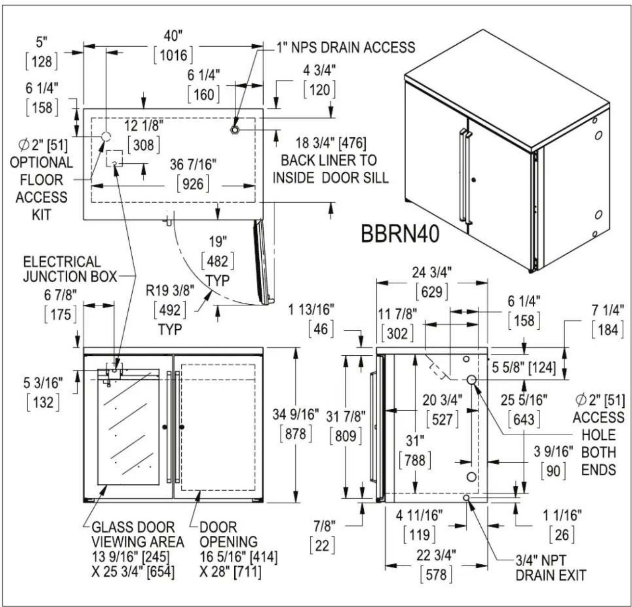
DIMENSIONS
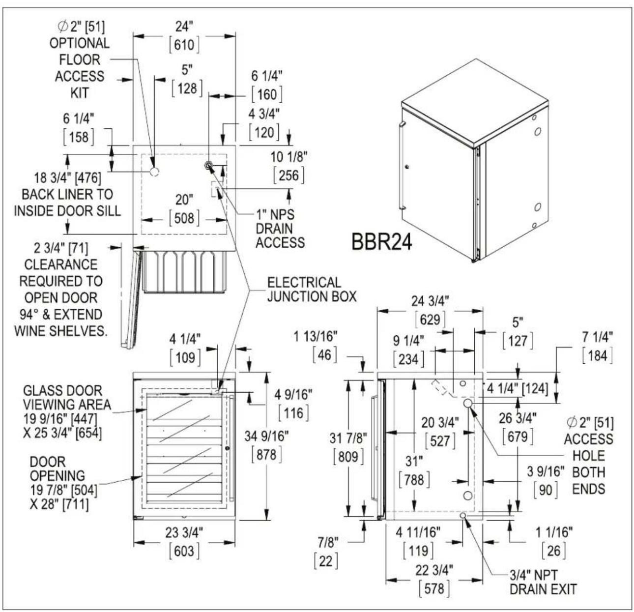
text_image
Ø2" [51] OPTIONAL FLOOR ACCESS KIT 6 1/4" [158] 18 3/4" [476] BACK LINER TO INSIDE DOOR SILL 2 3/4" [71] CLEARANCE REQUIRED TO OPEN DOOR 94° & EXTEND WINE SHELVES. GLASS DOOR VIEWING AREA 19 9/16" [447] X 25 3/4" [654] DOOR OPENING 19 7/8" [504] X 28" [711] 24" [610] 5" [128] 6 1/4" [160] 4 3/4" [120] 10 1/8" [256] 20" [508] 1" NPS DRAIN ACCESS ELECTRICAL JUNCTION BOX 24 3/4" [629] 1 13/16" [46] 9 1/4" [234] 5" [127] 7 1/4" [184] 4 9/16" [116] 34 9/16" [878] 31 7/8" [809] 4 1/4" [124] 20 3/4" [527] 26 3/4" [679] Ø2" [51] ACCESS HOLE BOTH ENDS 3 9/16" [90] 4 11/16" [119] 1 1/16" [26] 22 3/4" [578] 3/4" NPT DRAIN EXIT 23 3/4" [603]
text_image
48" [1220] BBR48 5" 72" [1829] BBR72 [128] 96" [2439] BBR96 6 1/4" 44" [1118] BBR48 7 3/4" [158] 68" [1727] BBR72 196 92" [2337] BBR96 37 5/8" [956] BBR48 42 5/8" [1083] BBR72 & BBR96 9 3/4" [248] 18 3/4" [476] BACK LINER TO INSIDE DOOR SILL Φ2" [51] OPTIONAL FLOOR ACCESS R23 3/8" [593] TYP 23" TYP [584] 2 3/4" [71] CLEARANCE REQUIRED TO OPEN DOOR 94° & EXTEND WINE SHELVES. ELECTRICAL JUNCTION BOX 4 1/2" [114] 5 WINE SHELVES 8 BOTTLES PER SHELF 11 1/4" [286] BBR48 20 3/4" [527] BBR72 32 3/4" [781] BBR96 23 3/4" [603] 1 13/16" [46] 34 9/16" [878] 31 7/8" [809] 7/8" [22] BBR96 BBR72 BBR48 24 3/4" [629] 3 9/16" [90] 4 7/8" [124] 7 1/4" [184] 26 1/16" [662] Φ2" [51] ACCESS HOLE BOTH ENDS 4 11/16" [119] 22 3/4" [578] 1 1/16" [26] 3/4" NPT DRAIN EXIT GLASS DOOR VIEWING AREA 13 9/16" [245] X 25 3/4" [654] DOOR OPENING 19 7/8" [504] X 28" [711]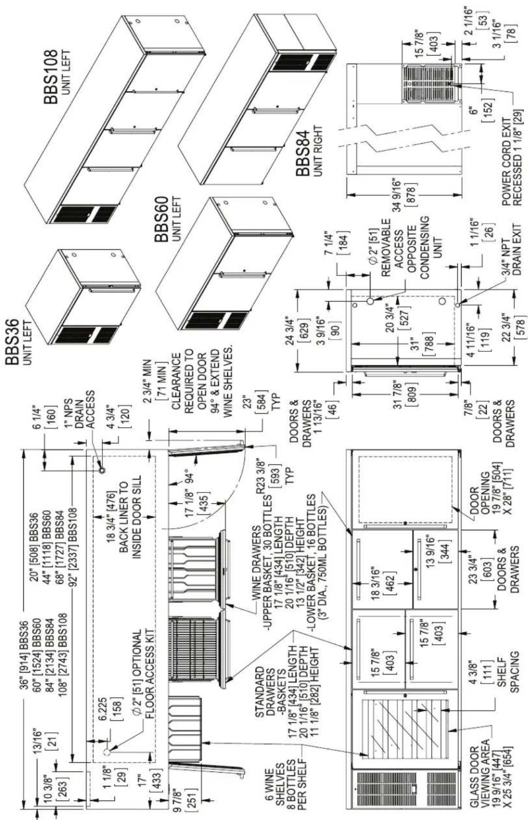
text_image
10 3/8" [263] 36" [914] BBS36 13/16" [21] 20" [508] BBS36 60" [1524] BBS60 84" [2134] BBS84 108" [2743] BBS108 44" [1118] BBS60 68" [1727] BBS84 92" [2337] BBS108 6 1/4" [160] 1" NPS DRAIN ACCESS 4 3/4" [120] 1 1/8" [29] 6.225 [158] 18 3/4" [476] BACK LINER TO INSIDE DOOR SILL 17 1/8" 94° [435] 9 7/8" [251] 2 3/4" MIN [71 MIN] CLEARANCE REQUIRED TO OPEN DOOR 94° & EXTEND WINE SHELVES. 23" [584] TYP STANDARD DRAWERS -BASKETS 17 1/8" [434] LENGTH 20 1/16" [510] DEPTH 11 1/8" [282] HEIGHT WINE DRAWERS -UPPER BASKET, 30 BOTTLES 17 1/8" [434] LENGTH 20 1/16" [510] DEPTH 13 1/2" [342] HEIGHT -LOWER BASKET, 16 BOTTLES (3" DIA., 750ML BOTTLES) R23 3/8" [593] TYP DOORS & DRAWERS 1 13/16" [46] 24 3/4" [629] 3 9/16" [90] 7 1/4" [184] GLASS DOOR VIEWING AREA 19 9/16" [447] X 25 3/4" [654] 4 3/8" [111] SHELF SPACING 23 3/4" [603] DOORS & DRAWERS DOOR OPENING 19 7/8" [504] X 28" [711] 31 7/8" [809] 20 3/4" [527] 31" [788] 7/8" [22] DOORS & DRAWERS 4 11/16" [119] 22 3/4" [578] 1 1/16" [26] 3/4" NPT DRAIN EXIT POWER CORD EXIT RECESSED 1 1/8" [29] BBS36 UNIT LEFT BBS108 UNIT LEFT BBS60 UNIT LEFT BBS84 UNIT RIGHT
text_image
5" [128] 6 1/4" [158] Ø2" [51] OPTIONAL FLOOR ACCESS KIT 40" [1016] 6 1/4" [160] 12 1/8" [308] 36 7/16" [926] 19" [482] TYP R19 3/8" [492] TYP ELECTRICAL JUNCTION BOX 6 7/8" [175] 5 3/16" [132] GLASS DOOR VIEWING AREA 13 9/16" [245] X 25 3/4" [654] DOOR OPENING 16 5/16" [414] X 28" [711] 1 NPS DRAIN ACCESS 4 3/4" [120] 18 3/4" [476] BACK LINER TO INSIDE DOOR SILL BBRN40 24 3/4" [629] 11 7/8" [302] 6 1/4" [158] 7 1/4" [184] 34 9/16" [878] 31 7/8" [809] 20 3/4" [527] 31" [788] 5 5/8" [124] 25 5/16" [643] Ø2" [51] ACCESS HOLE BOTH ENDS 3 9/16" [90] 4 11/16" [119] 1 1/16" [26] 22 3/4" [578] 3/4" NPT DRAIN EXIT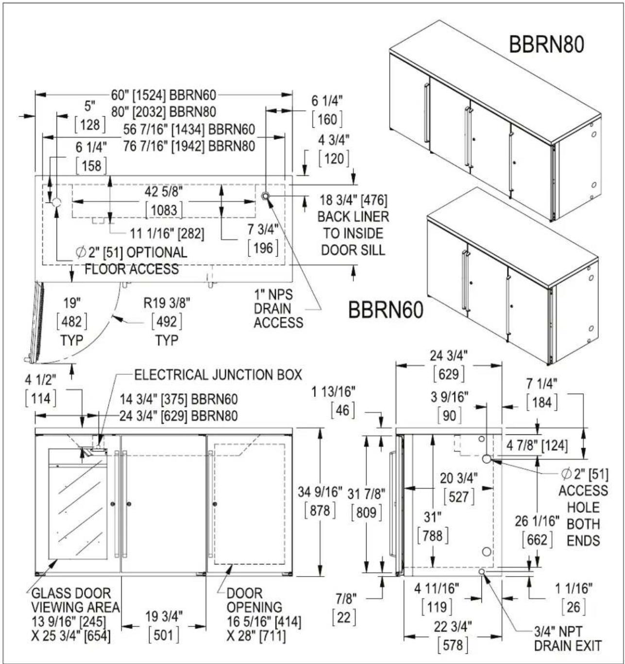
text_image
BBRN80 5" 60" [1524] BBRN60 [128] 80" [2032] BBRN80 56 7/16" [1434] BBRN60 6 1/4" 76 7/16" [1942] BBRN80 [158] 6 1/4" [160] 4 3/4" [120] 42 5/8" [1083] 11 1/16" [282] 7 3/4" [196] 18 3/4" [476] BACK LINER TO INSIDE DOOR SILL FLOOR ACCESS 19" [482] R19 3/8" [492] TYP 1" NPS DRAIN ACCESS BBRN60 ELECTRICAL JUNCTION BOX 14 3/4" [375] BBRN60 24 3/4" [629] BBRN80 1 13/16" [46] 24 3/4" [629] 3 9/16" [90] 7 1/4" [184] 34 9/16" 31 7/8" [878] [809] 4 7/8" [124] ∅2" [51] ACCESS HOLE BOTH ENDS GLASS DOOR VIEWING AREA 13 9/16" [245] X 25 3/4" [654] 19 3/4" [501] DOOR OPENING 16 5/16" [414] X 28" [711] 7/8" [22] 4 11/16" [119] 22 3/4" [578] 1 1/16" [26] 3/4" NPT DRAIN EXIT
text_image
32" [813] BBSN32 52" [1321] BBSN52 72" [1829] BBSN72 92" [2337] BBSN92 16 7/16" [418] BBSN32 36 7/16" [926] BBSN52 56 7/16" [1434] BBSN72 76 7/16" [1942] BBSN92 1 1/8" [29] 10 3/8" [263] 1 1/4" [158] 17" [433] 6 1/4" [160] 18 3/4" [476] BACK LINER TO INSIDE DOOR SILL 1" NPS DRAIN ACCESS φ2" [51] OPTIONAL FLOOR ACCESS KIT R19 3/8" [492] TYP 19" [482] TYP BBSN32 UNIT LEFT BBSN92 UNIT LEFT BBSN52 UNIT LEFT 24 3/4" [629] 3 9/16" [90] 1 13/16" [46] BBSN72 UNIT RIGHT 7 1/4" [184] φ2" [51] REMOVABLE ACCESS OPPOSITE CONDENSING UNIT 31 7/8" [809] DOOR OPENING 16 5/16" [414] X 28" [711] 7/8" [22] 4 11/16" [119] 22 3/4" [578] 1 1/16" [26] 3/4" NPT DRAIN EXIT POWER CORD EXIT RECESSED 1 1/8" [29] GLASS DOOR VIEWING AREA 13 9/16" [245] X 25 3/4" [654] 19 3/4" [501]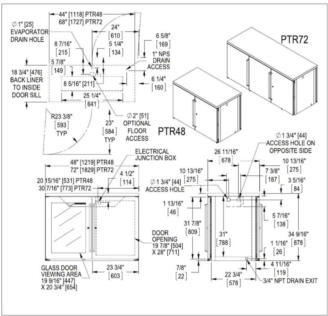
text_image
Φ1" [25] EVAPORATOR DRAIN HOLE 44" [1118] PTR48 68" [1727] PTR72 24" [610] 8 7/16" [215] 5 7/8" [149] 5 1/4" [134] 6 5/8" [169] 1" NPS DRAIN ACCESS 6 1/4" [160] 18 3/4" [476] BACK LINER TO INSIDE DOOR SILL 8 5/16" [211] 25 1/4" [641] R23 3/8" [593] TYP 23" [584] TYP Φ2" [51] OPTIONAL FLOOR ACCESS PTR48 Φ1 3/4" [44] ACCESS HOLE ON OPPOSITE SIDE ELECTRICAL JUNCTION BOX 48" [1219] PTR48 72" [1829] PTR72 4 1/2" [114] 20 15/16" [531] PTR48 30 7/16" [773] PTR72 Φ1 3/4" [44] ACCESS HOLE 1 13/16" [46] DOOR OPENING 19 7/8" [504] X 28" [711] 7/8" [22] 31 7/8" [809] 31" [788] 5 7/16" [138] 34 9/16" [26] 4 11/16" [119] GLASS DOOR VIEWING AREA 19 9/16" [447] X 20 3/4" [654] 23 3/4" [603] 3/4" NPT DRAIN EXIT PTR72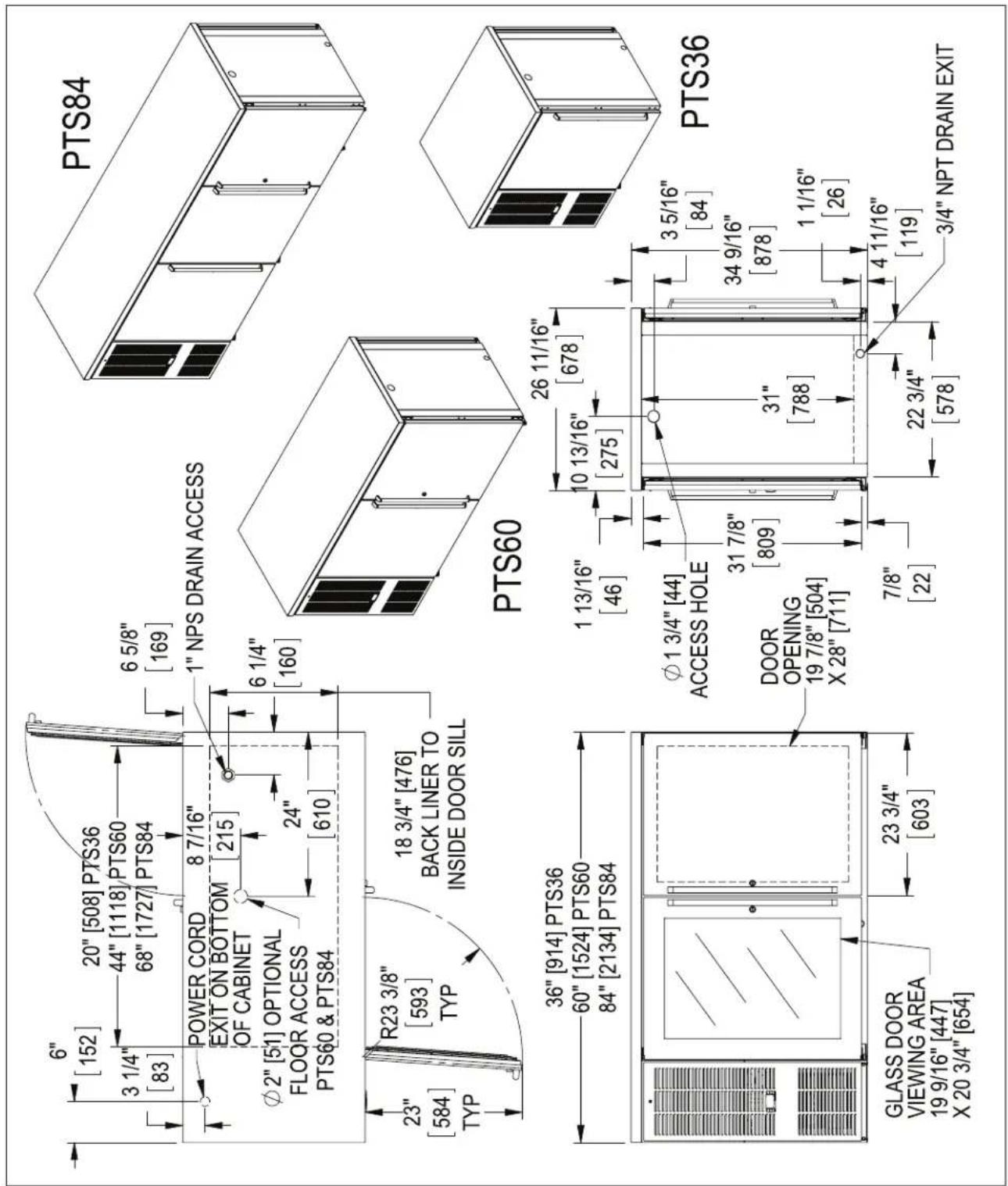
text_image
6" [152] 20" [508] PTS36 3 1/4" [83] 44" [1118] PTS60 68" [1727] PTS84 6 5/8" [169] POWER CORD EXIT ON BOTTOM OF CABINET 8 7/16" [215] φ2" [51] OPTIONAL FLOOR ACCESS PTS60 & PTS84 24" [610] 6 1/4" [160] R23 3/8" [593] TYP 18 3/4" [476] BACK LINER TO INSIDE DOOR SILL 23" [584] TYP 36" [914] PTS36 60" [1524] PTS60 84" [2134] PTS84 GLASS DOOR VIEWING AREA 19 9/16" [447] X 20 3/4" [654] 23 3/4" [603] PTS84 PTS60 26 11/16" [678] 1 13/16" [46] 10 13/16" [275] φ1 3/4" [44] ACCESS HOLE DOOR OPENING 19 7/8" [504] X 28" [711] 31 7/8" [809] 31" [788] 7/8" [22] 3 5/16" [84] 34 9/16" [878] 1 1/16" [26] 22 3/4" [578] 4 11/16" [119] 3/4" NPT DRAIN EXIT PTS36
text_image
44" [1118] SDBR48 5" 92" [2337] SDBR96 [128] 37 3/4" [958] SDBR48 42 5/8" [1083] SDBR96 6 1/4" [158] 1" NPS DRAIN ACCESS 4 3/4" [120] 18 3/4" [476] BACK LINER TO INSIDE DOOR SILL 9 1/16" [230] 7 3/4" [196] 6 1/4" [160] Ø2" [51] OPTIONAL FLOOR ACCESS 3/16" [5] DOOR HANDLE SDBR96 SDBR48 Ø2" [51] ACCESS HOLE 7 1/4" [184] 11 1/4" [286] 48" [1219] SDBR48 96" [2439] SDBR96 4 1/2" [114] ELECTRICAL JUNCTION BOX SHOWN WITH DOOR OPEN 3 15/16" [100] GLASS DOOR VIEWING AREA 18 1/2" [469] X 22 11/16" [577] DOOR OPENING 16 13/16" [427] X 25 3/8" [645] 3 9/16" [90] 31" [788] 19 5/16" [490] 3/4"NPT DRAIN EXIT 24 15/16" [633] 4 11/16" [119] INCLUDING DOOR HANDLE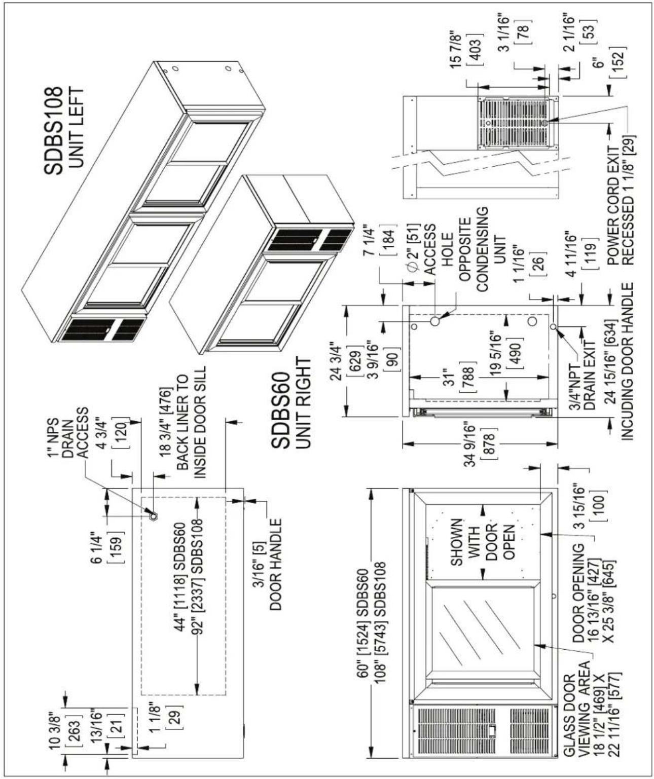
text_image
10 3/8" [263] 13/16" [21] 6 1/4" [159] 1" NPS DRAIN ACCESS 4 3/4" [120] 1 1/8" [29] 44" [1118] SDBS60 92" [2337] SDBS108 18 3/4" [476] BACK LINER TO INSIDE DOOR SILL 3/16" [5] DOOR HANDLE SDBS60 UNIT RIGHT SDBS108 UNIT LEFT 60" [1524] SDBS60 108" [5743] SDBS108 SHOWN WITH DOOR OPEN GLASS DOOR VIEWING AREA 18 1/2" [469] X 22 11/16" [577] DOOR OPENING 16 13/16" [427] X 25 3/8" [645] 3 15/16" [100] 24 3/4" [629] 3 9/16" [90] 34 9/16" [878] 31" [788] 19 5/16" [490] 7 1/4" [184] Ø2" [51] ACCESS HOLE OPPOSITE CONDENSING UNIT 1 1/16" [26] 3/4"NPT DRAIN EXIT 24 15/16" [634] INCLUDING DOOR HANDLE 4 11/16" [119] POWER CORD EXIT RECESSED 1 1/8" [29] 15 7/8" [403] 3 1/16" [78] 2 1/16" [53] 6" [152]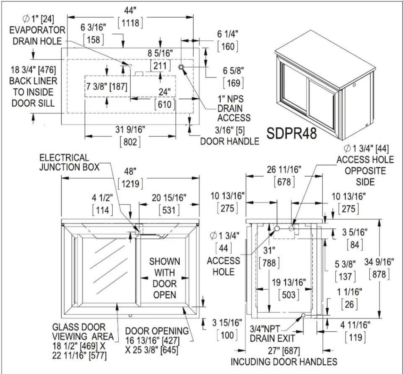

text_image
POWER CORD EXIT ON BOTTOM OF CABINET 6" [152] 6 1/4" [160] 6 5/8" [169] 3 1/4" [83] 18 3/4" [476] BACK LINER TO INSIDE DOOR SILL 44" [1118] 1" NPS DRAIN ACCESS 3/16" [5] DOOR HANDLE TYP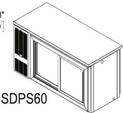
natural_image
Isometric line drawing of a wall-mounted device with two panels and a door, labeled 'SDPS60' (no other text or symbols)
text_image
60" [1524] SHOWN WITH DOOR OPEN GLASS DOOR VIEWING AREA 18 1/2" [469] X 22 11/16" [577] DOOR OPENING 16 13/16" [427] X 25 3/8" [645] 3 15/16" [100]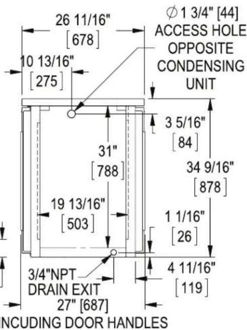
text_image
26 11/16" [678] 10 13/16" [275] 31" [788] 19 13/16" [503] 3/4"NPT DRAIN EXIT 27" [687] φ 1 3/4" [44] ACCESS HOLE OPPOSITE CONDENSING UNIT 3 5/16" [84] 34 9/16" [878] 1 1/16" [26] 4 11/16" [119] NCUDING DOOR HANDLES36" DUAL ZONE
DZS36
UNIT LEFT with 4 faucet Tee Tower.

natural_image
Technical line drawing of a mechanical device with open door and internal components (no text or symbols)DZS36
UNIT RIGHT
with (2) 2 faucet
Draft Arms.

natural_image
Isometric line drawing of a server rack unit with two water pumps and a central door (no text or symbols)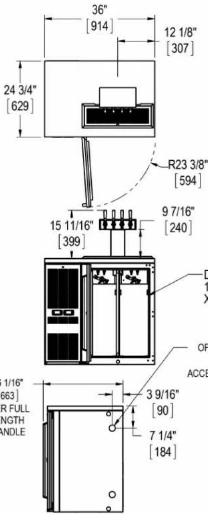
text_image
36" [914] 12 1/8" [307] 24 3/4" [629] R23 3/8" [594] 15 11/16" [399] 9 7/16" [240] D 1 X OP ACCE 1/16" [663] R FULL NGTH ANDLE 3 9/16" [90] 7 1/4" [184]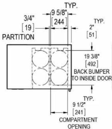
text_image
TYP. 3/4" [19] PARTITION 9 5/8" [244] TYP. 2" [51] 19 3/8" [492] BACK BUMPER TO INSIDE DOOR TYP. 9 1/2" [241] COMPARTMENT OPENING
text_image
10 1/2" [267] 6 7/8" [174] 7 9/16" [193] 23 1/4" [591]
text_image
16 9/16" [421] 10 5/8" [270] 31 7/8" [809] DOOR 34 9/16" [878]
text_image
REAR VIEW 3 1/16" [78] 15 7/8" [403] 2 1/16" [52] POWER CORD EXIT RECESSED 1 1/8" [29] 6" [152]95119 REV C CJT 10/22/2013 Sheet 2 of 2

text_image
60" DUAL ZONE DZS60 UNIT RIGHT Ø2" [51] OPTIONAL FLOOR ACCESS KIT 6 1/4" [158] 17" [433] 4 3/4" [118] 6 1/4" [159] 13/16" [21] 1 1/8" [29] 1" NPS DRAIN ACCESS 20" [508] TYP 9 7/8" [251] 17 9/16" [446] 6 WINE SHELVES 8 BOTTLES PER SHELF STANDARD DRAWERS -BASKETS 17 1/8" [434] LENGTH 20 1/16" [510] DEPTH 11 1/8" [282] HEIGHT GLASS DOOR VIEWING AREA 19 9/16" [447] X 25 3/4" [654] 4 3/8" [111] SHELF SPACING POWER CORD EXIT RECESSED 1 1/8" [29] 60" [1524] 10 3/8" [263] 59 15/16" [1522] 14 3/4" [375] 94° R23 3/8" [593] WINE DRAWERS -UPPER BASKET, 30 BOTTLES 17 1/8" [434] LENGTH 20 1/16" [510] DEPTH 13 1/2" [342] HEIGHT -Lower BASKET, 16 BOTTLES (3" DIA., 750ML BOTTLES) DOORS & DRAWERS 1 13/16" [46] 34 9/16" [878] 18 3/16" [462] 13 9/16" [344] 23 3/4" [603] DOORS & DRAWERS DOOR OPENING 19 7/8" [504] X 28" [711] 7/8" [22] DOORS & DRAWERS 7 1/4" [184] 24 3/4" [629] 3 9/16" [90] 31 7/8" [809] 3/4" NPT DRAIN EXIT 4 11/16" [119] 22 3/4" [578] 1 1/16" [26] 26 1/16" [662] OVER FULL LENGTH S.S. HANDLE 95119 Rev C CJT 10/21/13 SHEET 1 OF 2


text_image
15 7/8" [403] 3 1/16" [78] 2 1/16" [53] 6" [152] ER CORD EXIT ESSED 1 1/8" [29] BACK VIEW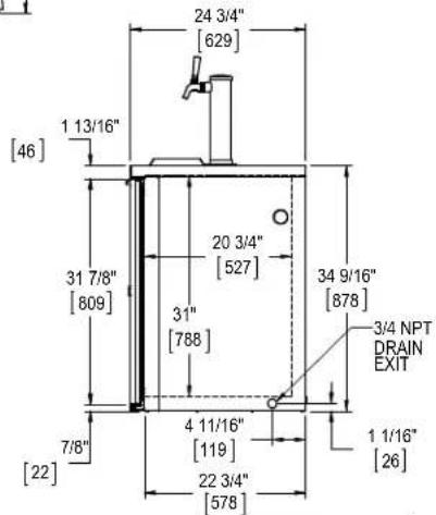
text_image
24 3/4" [629] 1 13/16" [46] 31 7/8" [809] 20 3/4" [527] 31" [788] 34 9/16" [878] 3/4 NPT DRAIN EXIT 1 1/16" [26] 7/8" [22] 4 11/16" [119] 22 3/4" [578]9 R
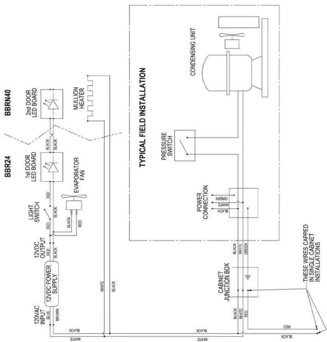
WIRING DIAGRAMS
BBR24/BBRN40
57342A-99-120-RevA
NOTE: FIELD WIRING FROM CABINET JUNCTION BOX TO CONDENSING UNIT MUST COMPLY WITH ALL LOCAL AND NATIONAL ELECTRICAL CODES
flowchart
graph TD
    subgraph BBR24
        A["12VDC POWER SUPPLY"] -->|BROWN| B["BROWN"]
        B --> C["12VDC OUTPUT RED"]
        C --> D["BLACK"]
        D --> E["1st DOOR LED BOARD"]
        E --> F["BLACK"]
        F --> G["MULLION HEATER"]
    end
    subgraph BBRN40
        H["2nd DOOR LED BOARD"] --> I["2nd DOOR LED BOARD"]
    end
    J["TYPICAL FIELD INSTALLATION"]
    K["CABINET JUNCTION BOX"] --> L["POWER CONNECTION"]
    L --> M["PRESSURE SWITCH"]
    M --> N["CONDENSING UNIT"]
    O["THESE WIRES CAPPED IN SINGLE CABINET INSTALLATIONS"] --> P["RED"]
    Q["WHITE"] --> R["BLACK"]
    S["WHITE"] --> T["BLACK"]
    U["Black"] --> V["RED"]
    W["Black"] --> X["GREEN"]
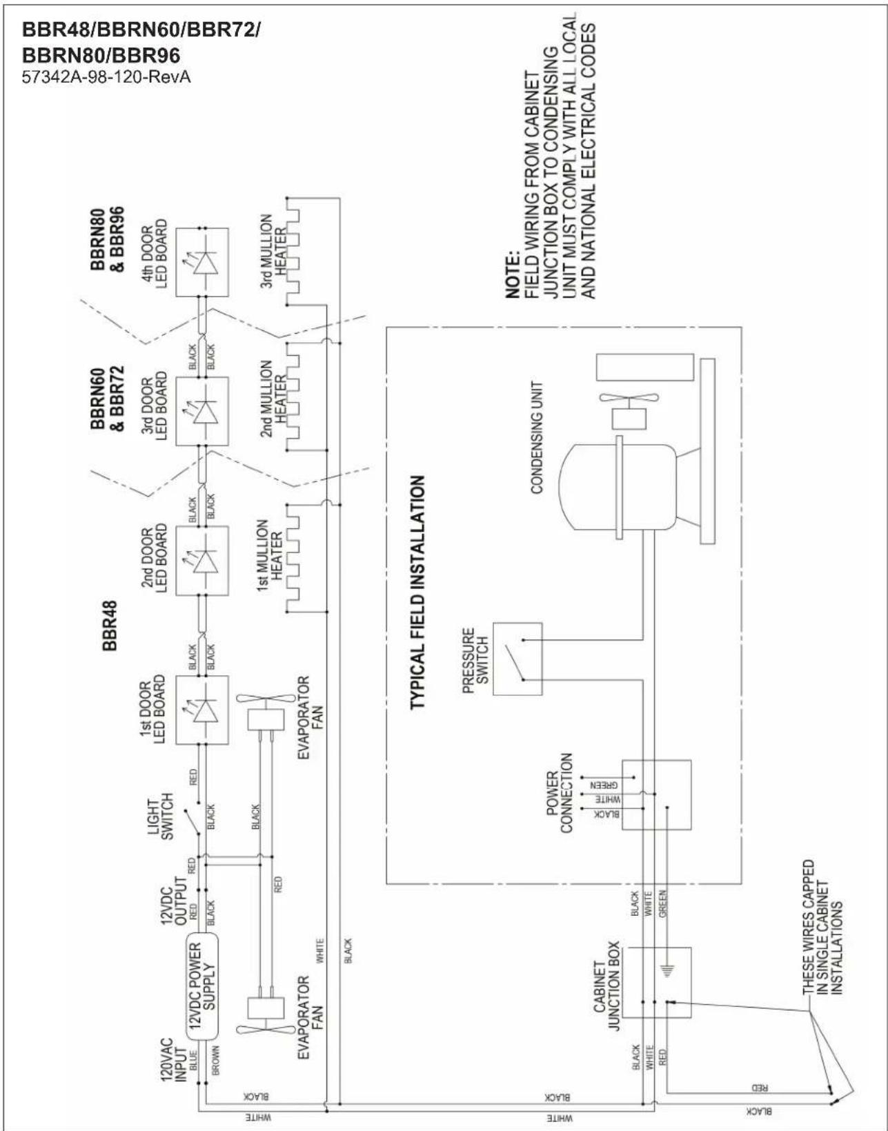
flowchart
graph TD
    subgraph "BBR48"
        A["12VAC INPUT BLUE"] --> B["12VDC POWER SUPPLY"]
        C["BROWN"] --> B
        D["EVAPORATOR FAN"] --> B
        E["WHITE"] --> B
    end

    subgraph "BBR60 & BBR72"
        F["1st DOOR LED BOARD"] --> G["1st MULLION HEATER"]
        H["2nd DOOR LED BOARD"] --> I["2nd MULLION HEATER"]
        J["3rd DOOR LED BOARD"] --> K["3rd MULLION HEATER"]
        L["4th DOOR LED BOARD"] --> M["4th MULLION HEATER"]

    end

    subgraph "BBR80 & BBR96"
        N["1st DOOR LED BOARD"] --> O["1st MULLION HEATER"]
        P["2nd DOOR LED BOARD"] --> Q["2nd MULLION HEATER"]
        R["3rd DOOR LED BOARD"] --> S["3rd MULLION HEATER"]

    end

    subgraph "TYPICAL FIELD INSTALLATION"
        T["PRESSURE SWITCH"] --> U["CABINET JUNCTION BOX"]
        V["POWER CONNECTION"] --> W["CABINET JUNCTION BOX"]
        X["CONDENSING UNIT"] --> Y["CABINET JUNCTION BOX"]
        Z["THESE WIRES CAPPED IN SINGLE CABINET INSTALLATIONS"]
    end

    style "BBR48" fill:#f9f,stroke:#333
    style "BBR60 & BBR72" fill:#ccf,stroke:#333
    style "BBR80 & BBR96" fill:#cfc,stroke:#333
    style "BBR48/BBR60/BBR72/" fill:#fcc,stroke:#333

flowchart
graph LR
    subgraph_BBRLP48["BBRLP48"]
        A["120VAC INPUT"] --> B["BROWN"]
        B --> C["12VDC POWER SUPPLY"]
        C --> D["12VDC OUTPUT"]
        D --> E["BLEK"]
        E --> F["BLACK"]
        F --> G["EVAPORATOR FAN"]
        G --> H["BLCK"]
        H --> I["BLACK"]
        I --> J["EVAPORATOR FAN"]
        J --> K["BLCK"]
        K --> L["Light SWITCH"]
        L --> M["BLCK"]
        M --> N["1st DOOR LED BOARD"]
        N --> O["BLCK"]
        O --> P["2nd DOOR LED BOARD"]
        P --> Q["BLCK"]
        Q --> R["1st MULLION HEATER"]
        R --> S["BLCK"]
        S --> T["3rd DOOR LED BOARD"]
        T --> U["BLCK"]
        U --> V["3rd MULLION HEATER"]
        V --> W["BLCK"]
    end

    subgraph_BBRLP72["BBRLP72"]
        X["3rd DOOR LED BOARD"] --> Y["BLCK"]
        Y --> Z["BLACK"]
        Z --> AA["2nd MULLION HEATER"]
        AA --> AB["BLCK"]
        AB --> AC["3rd MULLION HEATER"]
        AC --> AD["BLCK"]
    end

    subgraph_BBRLP96["BBRLP96"]
        AE["4th DOOR LED BOARD"] --> AF["BLCK"]
        AF --> AG["BLACK"]
        AG --> AH["3rd MULLION HEATER"]
        AH --> AI["BLCK"]
    end

    subgraph_Typical_Field_Installation["TYPICAL FIELD INSTALLATION"]
        AJ["TYPICAL FIELD INSTALLATION"] --> AK["CABINET JUNCTION BOX"]
        AK --> AL["BLCK"]
        AL --> AM["WHITE"]
        AL --> AN["BLCK"]
        AN --> AO["GREEN"]
        AP["TYPICAL FIELD INSTALLATION"] --> AQ["PRESSURE SWITCH"]
        AQ --> AR["BLCK"]
        AR --> AS["WHITE"]
        AR --> AT["BLCK"]
        AU["TYPICAL FIELD INSTALLATION"] --> AV["CONDENSING UNIT"]
    end

    style BBRLP48 fill:#f9f,stroke:#333
    style BBRLP72 fill:#ccf,stroke:#333
    style BBRLP96 fill:#cfc,stroke:#333

flowchart
graph TD
    A["NEMA 5-15P"] --> B["EVAPORATOR FAN"]
    B --> C["TO CONDENSING UNIT"]
    C --> D["CONDENSING UNIT"]
    D --> E["CONDENSING UNT"]
    E --> F["CONDENSING UNT"]
    F --> G["CONDENSING UNT"]
    G --> H["CONDENSING UNT"]
    H --> I["CONDENSING UNT"]
    I --> J["CONDENSING UNT"]
    J --> K["CONDENSING UNT"]
    K --> L["CONDENSING UNT"]
    L --> M["CONDENSING UNT"]
    M --> N["CONDENSING UNT"]
    N --> O["CONDENSING UNT"]
    O --> P["CONDENSING UNT"]
    P --> Q["CONDENSING UNT"]
    Q --> R["CONDENSING UNT"]
    R --> S["CONDENSING UNT"]
    S --> T["CONDENSING UNT"]
    T --> U["CONDENSING UNT"]
    U --> V["CONDENSING UNT"]
    V --> W["CONDENSING UNT"]
    W --> X["CONDENSING UNT"]
    X --> Y["CONDENSING UNT"]
    Y --> Z["CONDENSING UNT"]
    Z --> AA["CONDENSING UNT"]
    AA --> AB["CONDENSING UNT"]
    AB --> AC["CONDENSING UNT"]
    AC --> AD["CONDENSING UNT"]
    AD --> AE["CONDENSING UNT"]
    AE --> AF["CONDENSING UNT"]
    AF --> AG["CONDENSING UNT"]
    AG --> AH["CONDENSING UNT"]
    AH --> AI["CONDENSING UNT"]
    AI --> AJ["CONDENSING UNT"]
    AJ --> AK["CONDENSING UNT"]
    AK --> AL["CONDENSING UNT"]
    AL --> AM["CONDENSING UNT"]
    AM --> AN["CONDENSING UNT"]
    AN --> AO["CONDENSING UNT"]
    AO --> AP["CONDENSING UNT"]
    AP --> AQ["CONDENSING UNT"]
    AQ --> AR["CONDENSING UNT"]
    AR --> AS["CONDENSING UNT"]
    AS --> AT["CONDENSING UNT"]
    AT --> AU["CONDENSING UNT"]
    AU --> AV["CONDENSING UNT"]
    AV --> AW["CONDENSING UNT"]
    AW --> AX["CONDENSING UNT"]
    AX --> AY["CONDENSING UNT"]
    AY --> AZ["CONDENSING UNT"]
    AZ --> BA["CONDENSING UNT"]
    BA --> BB["CONDENSING UNT"]
    BB --> BC["CONDENSING UNT"]
    BC --> BD["CONDENSING UNT"]
    BD --> BE["CONDENSING UNT"]
    BE --> BF["CONDENSING UNT"]
    BF --> BG["CONDENSING UNT"]
    BG --> BH["CONDENSING UNT"]
    BH --> BI["CONDENSING UNT"]
    BI --> BJ["CONDENSING UNT"]
    BJ --> BK["CONDENSING UNT"]
    BK --> BL["CONDENSING UNT"]
    BL --> BM["CONDENSING UNT"]
    BM --> BN["CONDENSING UNT"]
    BN --> BO["CONDENSING UNT"]
    BO --> BP["CONDENSING UNT"]
    BP --> BQ["CONDENSING UNT"]
    BQ --> BR["CONDENSING UNT"]
    BR --> BS["CONDENSING UNT"]
    BS --> BT["CONDENSING UNT"]
    BT --> BU["CONDENSING UNT"]
    BU --> BV["CONDENSING UNT"]
    BV --> BW["CONDENSING UNT"]
    BW --> BX["BBS36 BBS36C BBSN32"]
    BX --> BY["BBS60 BBSN52"]
    BY --> BZ["BBS84 BBSN72"]
    BZ --> CA["BBS108 BBSN92"]
    CA --> CB[BBS36BBSN32BBSN52BBSN72BBSN92BBSN36BBSN36BBSN52BBSN72BBSN92BBSN36BBSN36BBSN52BBSN72BBSN92BBSN36BBSN52BBSN72BBSN92BBSN92BBSN36BBSN36BBSN52BBSN52BBSN72BBSN72BBSN92BBSN92BBSN36BBSN52BBSN72BBSN72BBSN92BBSN92BBSN36BBSN52BBSN72BBSN72BBSN92BBSN92BBSN36BBSN52BBSN72BBSN72BBSN72BBSN92BBSN92BBSN36BBSN52BBSN72BBSN72BBSN72BBSN92BBSN92BBSN36BBSN52BBSN72BBSN72BBSN72BBSN72BBSN92BBSN92BBSN36BBSN52BBSN72BBSN72BBSN72BBSN72BBSN92BBSN92BBSN36BBSN52BBSN72BBSN72BBSN72BBSN72BBSN72BBSN92BBSN92BBSN36BBSN52BBSN72BBSN72BBSN72BBSN72BBSN72BBSN92BBSN92BBSN36BBSN52BBSN72BBSN72BBSN92BBSN92BBSN36BBSN52BBSN72BBSN72BBSN72BBSN72BBSN72BBSN92BBSN92BBSN36BBSN52BBSN72BBSN72BBSN72BBSN72BBSN92BBSN92BBSN36BBSN52BBSN72BBSN72BBSN72BBSN92BBSN92BBSN36BBSNSW
    style A fill:#f9f,stroke:#333
    style B fill:#ccf,stroke:#333
    style C fill:#cfc,stroke:#333
    style D fill:#fcc,stroke:#333
    style E fill:#ffc,stroke:#333
    style F fill:#fcc,stroke:#333
    style G fill:#fcc,stroke:#333
    style H fill:#fcc,stroke:#333
    style I fill:#fcc,stroke:#333
    style J fill:#fcc,stroke:#333
    style K fill:#fcc,stroke:#333
    style L fill:#fcc,stroke:#333
    style M fill:#fcc,stroke:#333
    style N fill:#fcc,stroke:#333
    style O fill:#fcc,stroke:#333
    style P fill:#fcc,stroke:#333
    style Q fill:#fcc,stroke:#333
    style R fill:#fcc,stroke:#333
    style S fill:#fcc,stroke:#333
    style T fill:#fcc,stroke:#333
    style U fill:#fcc,stroke:#333
    style V fill:#fcc,stroke:#333
    style W fill:#fcc,stroke:#333
    style X fill:#fcc,stroke:#333
    style Y fill:#fcc,stroke:#333
    style Z fill:#fcc,stroke:#333
    style AA fill:#fcc,stroke:#333
    style AB fill:#fcc,stroke:#333
    style AC fill:#fcc,stroke:#333
    style AD fill:#fcc,stroke:#333
    style AE fill:#fcc,stroke:#333
    style AF fill:#fcc,stroke:#333
    style AG fill:#fcc,stroke:#333
    style AH fill:#fcc,stroke:#333
    style AI fill:#fcc,stroke:#333
    style AJ fill:#fcc,stroke:#333
    style AK fill:#fcc,stroke:#333
    style AL fill:#fcc,stroke:#333
    style AM fill:#fcc,stroke:#333
    style AN fill:#fcc,stroke:#333
    style AO fill:#fcc,stroke:#333
    style AP fill:#fcc,stroke:#333
    style AQ fill:#fcc,stroke:#333
    style AR fill:#fcc,stroke:#333
    style AS fill:#fcc,stroke:#333
    style AT fill:#fcc,stroke:#333
    style AU fill:#fcc,stroke:#333
    style AV fill:#fcc,stroke:#333
    style AW fill:#fcc,stroke:#333
    style AX fill:#fcc,stroke:#333
    style AY fill:#fcc,stroke:#333
    style AZ fill:#fcc,stroke:#333
    style BA fill:#fcc,stroke:#333
    style BB fill:#fcc,stroke:#333
    style BC fill:#fcc,stroke:#333
    style BD fill:#fcc,stroke:#333
    style BE fill:#fcc,stroke:#333
    style BF fill:#fcc,stroke:#333
    style BG fill:#fcc,stroke:#333
    style BH fill:#fcc,stroke:#333
    style BI fill:#fcc,stroke:#333
    style BJ fill:#fcc,stroke:#333
    style BK fill:#fcc,stroke:#333
    style BL fill:#fcc,stroke:#�4e6e6e4e4e6e6e6e4e6e6e6e6e6e6e6e6e6e6e6e6e6e6e6e6e6e6e6e6e6e6e6e6e6e6e6e6e6e6e6e6e6e6e6e6e6e6e6e6e6e6e6e6e6e6e6e6e6e6e8b dBND CONTROLLER
BBS/BBSN
57342C-97-120
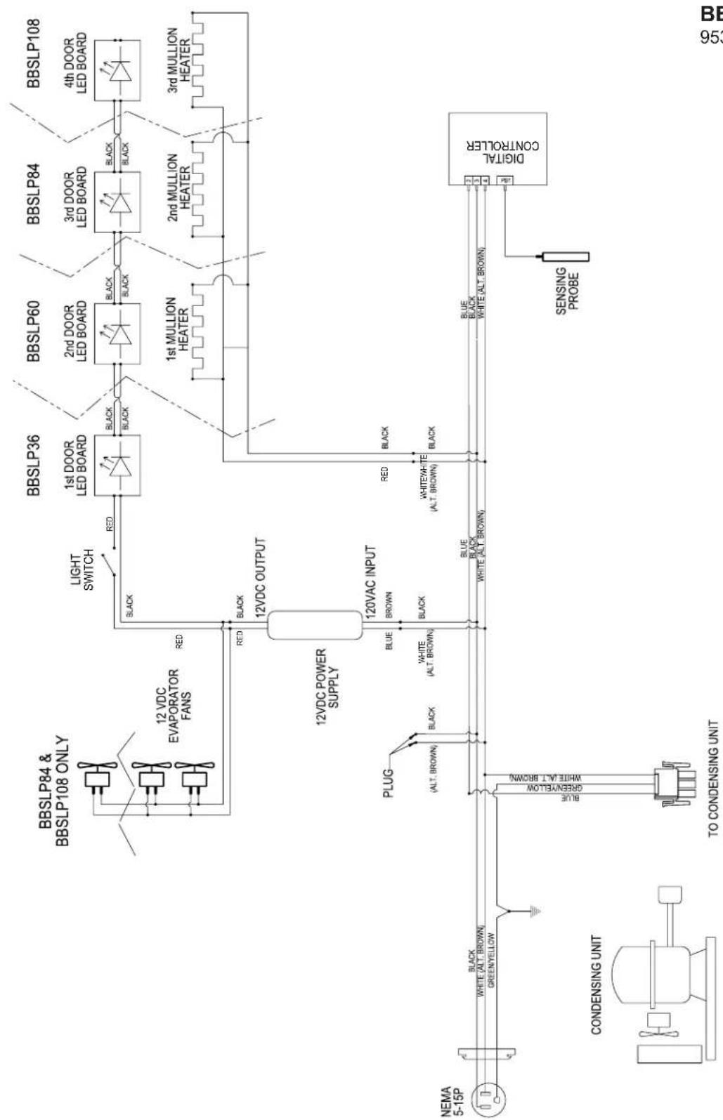
flowchart
graph TD
    A["NEMA 5-15P"] -->|BLACK| B["PLUG (ALT. BROWN)"]
    B --> C["CONDENSING UNIT"]
    C --> D["TO CONDENSING UNIT"]
    D --> E["12VDC POWER SUPPLY"]
    E --> F["12VDC OUTPUT"]
    F --> G["12VDC EVAPORATOR FANS"]
    G --> H["BBSLP84 & BBSLP108 ONLY"]
    H --> I["Light SWITCH"]
    I --> J["1st DOOR LED BOARD"]
    J --> K["BBSLP36"]
    K --> L["1st DOOR LED BOARD"]
    L --> M["BBSLP60"]
    M --> N["2nd DOOR LED BOARD"]
    N --> O["BBSLP84"]
    O --> P["3rd DOOR LED BOARD"]
    P --> Q["BBSLP108"]
    Q --> R["4th DOOR LED BOARD"]
    R --> S["1st MULLION HEATER"]
    S --> T["2nd MULLION HEATER"]
    T --> U["3rd MULLION HEATER"]
    U --> V["DIGITAL CONTROLLER"]
    V --> W["SENSING PROBE"]
    W --> X["BLUE BLACK WHITE (ALT. BROWN)"]
    X --> Y["BLUE BLACK WHITE (ALT. BROWN)"]
    Y --> Z["BLUE BLACK WHITE (ALT. BROWN)"]
    Z --> AA["BLUE BLACK WHITE (ALT. BROWN)"]
    AA --> AB["BLUE BLACK WHITE (ALT. BROWN)"]
    AB --> AC["BLUE BLACK WHITE (ALT. BROWN)"]
    AC --> AD["BLUE BLACK WHITE (ALT. BROWN)"]
    AD --> AE["BLUE BLACK WHITE (ALT. BROWN)"]
    AE --> AF["BLUE BLACK WHITE (ALT. BROWN)"]
    AF --> AG["BLUE BLACK WHITE (ALT. BROWN)"]
    AG --> AH["BLUE BLACK WHITE (ALT. BROWN)"]
    AH --> AI["BLUE BLACK WHITE (ALT. BROWN)"]
    AI --> AJ["BLUE BLACK WHITE (ALT. BROWN)"]
    AJ --> AK["BLUE BLACK WHITE (ALT. BROWN)"]
    AK --> AL["BLUE BLACK WHITE (ALT. BROWN)"]
    AL --> AM["BLUE BLACK WHITE (ALT. BROWN)"]
    AM --> AN["BLUE BLACK WHITE (ALT. BROWN)"]
    AN --> AO["BLUE BLACK WHITE (ALT. BROWN)"]
    AO --> AP["BLUE BLACK WHITE (ALT. BROWN)"]
    AP --> AQ["BLUE BLACK WHITE (ALT. BROWN)"]
    AQ --> AR["BLUE BLACK WHITE (ALT. BROWN)"]
    AR --> AS["BLUE BLACK WHITE (ALT. BROWN)"]
    AS --> AT["BLUE BLACK WHITE (ALT. BROWN)"]
    AT --> AU["BLUE BLACK WHITE (ALT. BROWN)"]
    AU --> AV["BLUE BLACK WHITE (ALT. BROWN)"]
    AV --> AW["BLUE BLACK WHITE (ALT. BROWN)"]
    AW --> AX["BLUE BLACK WHITE (ALT. BROWN)"]
    AX --> AY["BLUE BLACK WHITE (ALT. BROWN)"]
    AY --> AZ["BLUE BLACK WHITE (ALT. BROWN)"]
    AZ --> BA["BLUE BLACK WHITE (ALT. BROWN)"]
    BA --> BB["BLUE BLACK WHITE (ALT. BROWN)"]
    BB --> BC["BLUE BLACK WHITE (ALT. BROWN)"]
    BC --> BD["BLUE BLACK WHITE (ALT. BROWN)"]
    BD --> BE["BLUE BLACK WHITE (ALT. BROWN)"]
    BE --> BF["BLUE BLACK WHITE (ALT. BROWN)"]
    BF --> BG["BLUE BLACK WHITE (ALT. BROWN)"]
    BG --> BH["BLUE BLACK WHITE (ALT. BROWN)"]
    BH --> BI["BLUE BLACK WHITE (ALT. BROWN)"]
    BI --> BJ["BLUE BLACK WHITE (ALT. BROWN)"]
    BJ --> BK["BLUE BLACK WHITE (ALT. BROWN)"]
    BK --> BL["BLUE BLACK WHITE (ALT. BROWN)"]
    BL --> BM["BLUE BLACK WHITE (ALT. BROWN)"]
    BM --> BN["BLUE BLACK WHITE (ALT. BROWN)"]
    BN --> BO["BLUE BLACK WHITE (ALT. BROWN)"]
    BO --> BP["BLUE BLACK WHITE (ALT. BROWN)"]
    BP --> BQ["BLUE BLACK WHITE (ALT. BROWN)"]
    BA --> BR["Digital Controller"]
BBSLP
95321C-120

flowchart
graph TD
    A["NEMA 5-15P"] --> B["CONDENSING UNIT"]
    B --> C["TO CONDENSING UNIT"]
    C --> D["EVAPORATOR FAN"]
    D --> E["12VDC OUTPUT"]
    E --> F["12VDC POWER SUPPLY"]
    F --> G["120VAC INPUT"]
    G --> H["BBS36 BBS36C BBSN32"]
    H --> I["1st DOOR LED BOARD"]
    I --> J["BLACK"]
    J --> K["1st MULLION HEATER"]
    K --> L["BBS60 BBSN52"]
    L --> M["2nd DOOR LED BOARD"]
    M --> N["BLACK"]
    N --> O["1st MULLION HEATER"]
    O --> P["BBS84 BBSN72"]
    P --> Q["3rd DOOR LED BOARD"]
    Q --> R["BLACK"]
    R --> S["1st MULLION HEATER"]
    S --> T["BBS108 BBSN92"]
    T --> U["4th DOOR LED BOARD"]
    U --> V["3rd MULLION HEATER"]
    V --> W["DRAWER MULLION HEATER"]
    W --> X["BBS SERIES - DRAWER MULLION HEATER(S) CAN BE CONNECTED TO ANY HEATER JUNCTION(S) BASED ON CUSTOMER OPTIONS."]
    X --> Y["SENSING PROBE"]
    Y --> Z["Digital CONTROLLER"]
    Z --> AA["BLUE BLACK"]
    AA --> AB["WHITE (ALT. BROWN)"]
    AB --> AC["GREEN YELLOW"]
    AC --> AD["BLACK"]
    AD --> AE["WHITE (ALT. BROWN)"]
    AE --> AF["BLACK"]
    AF --> AG["BLUE BLACK"]
    AG --> AH["WHITE (ALT. BROWN)"]
    AH --> AI["BLACK"]
    AI --> AJ["12VDC OUTPUT"]
    AJ --> AK["12VDC POWER SUPPLY"]
    AK --> AL["BWS36 BBS36C BBSN32"]
    AL --> AM["LIGHT SWITCH"]
    AM --> AN["RED"]
    AN --> AO["BLACK"]
    AO --> AP["1st DOOR LED BOARD"]
    AP --> AQ["BLACK"]
    AQ --> AR["1st MULLION HEATER"]
    AR --> AS["BBS60 BBSN52"]
    AS --> AT["2nd DOOR LED BOARD"]
    AT --> AU["BLACK"]
    AU --> AV["1st MULLION HEATER"]
    AV --> AW["BBS84 BBSN72"]
    AW --> AX["3rd DOOR LED BOARD"]
    AX --> AY["BLACK"]
    AY --> AZ["1st MULLION HEATER"]
    AZ --> BA["BBS108 BBSN92"]
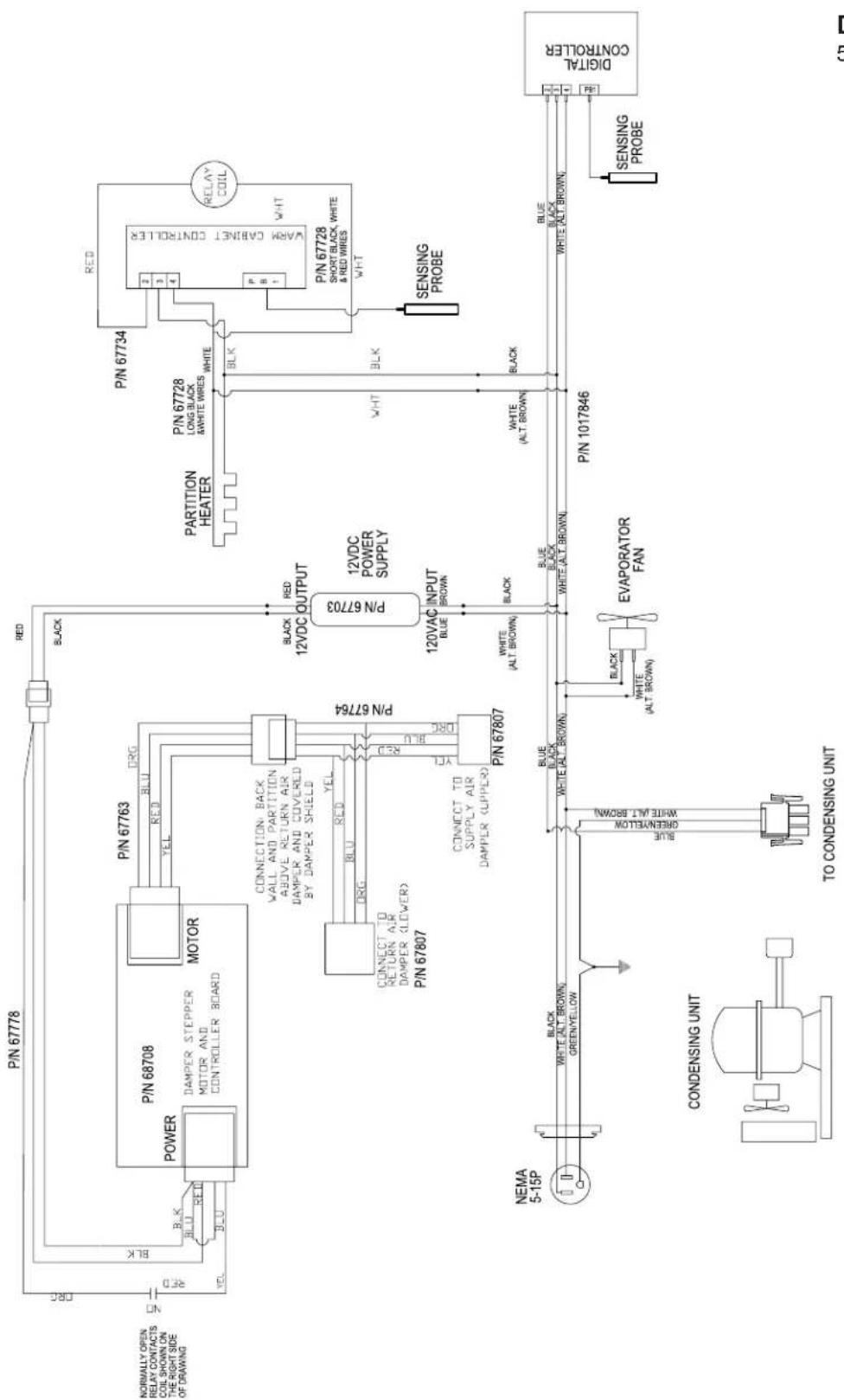
flowchart
graph TD
    A["NORMALLY OPEN RELAY CONTACTS COIL SHOWN ON THE RIGHT SIDE OF DRAWING"] --> B["POWER"]
    B --> C["P/N 68708 DAMPER STEPPER MOTOR AND CONTROLLER BOARD"]
    C --> D["MOTOR"]
    D --> E["P/N 67763 DRG"]
    E --> F["12VDC OUTPUT"]
    F --> G["P/N 67703 12VDC POWER SUPPLY"]
    G --> H["P/N 67734"]
    H --> I["RELAY COIL VARM CABINET CONTROLLER"]
    I --> J["SENSING PROBE"]
    J --> K["Digital CONTROLLER"]
    L["NEMA 5-15P"] --> M["BLK BLK RED BLU RED YEL"]
    M --> N["CONNECTION BACK WALL AND PARTITION ABOVE RETURN AIR DAMPER AND COVERED BY DAMPER SHIELD"]
    N --> O["CONNECT TO RETURN AIR DAMPER (LOWER) P/N 67807"]
    O --> P["CONNECT TO SUPPLY AIR DAMPER (UPPER)"]
    P --> Q["P/N 67807"]
    Q --> R["BLUE BLACK WHITE (ALT. BROWN)"]
    R --> S["EVAPORATOR FAN"]
    S --> T["CONDENSING UNIT"]
    T --> U["TO CONDENSING UNIT"]
    U --> V["BLK BLK RED BLU RED YEL"]
    V --> W["BLACK RED 12VDC OUTPUT"]
    W --> X["P/N 67728 LONG BLACK &WHITE WIRES WHITE BLK BLK WHT"]
    X --> Y["P/N 67728 SHORT BLACK, WHITE & RED WIRES WHT"]
    Y --> Z["SENSING PROBE"]
    AA["MINIMUM DEPTED OUT"] --> AB[RED BLACK BLK BLK BLK BLK BLK BLK BLK BLK BLK BLK BLK BLK BLK BLK BLK BLK BLK BLK BLK BLK BLK BLK BLK BLK BLK BLK BLK BLK BLK BLK BLK BLK BLK BLK BLK BLK BLK BLK BLK BLK BLK BLK BLK BLK BLK BLK BLK BLK BLK BLK BLk
    style A fill:#f9f,stroke:#333
    style B fill:#ccf,stroke:#333
    style C fill:#cfc,stroke:#333
    style D fill:#fcc,stroke:#333
    style E fill:#cff,stroke:#333
    style F fill:#ffc,stroke:#333
    style G fill:#ffc,stroke:#333
    style H fill:#ffc,stroke:#333
    style I fill:#ffc,stroke:#333
    style J fill:#ffc,stroke:#333
    style K fill:#ffc,stroke:#333
    style L fill:#ffc,stroke:#333
    style M fill:#ffc,stroke:#333
    style N fill:#ffc,stroke:#333
    style O fill:#ffc,stroke:#333
    style P fill:#ffc,stroke:#333
    style Q fill:#ffc,stroke:#333
    style R fill:#ffc,stroke:#333
    style S fill:#ffc,stroke:#333
    style T fill:#ffc,stroke:#333
    style U fill:#ffc,stroke:#333
    style V fill:#ffc,stroke:#333
    style W fill:#ffc,stroke:#333
    style X fill:#ffc,stroke:#333
    style Y fill:#ffc,stroke:#333
    style Z fill:#ffc,stroke:#333
    style AA fill:#fff,stroke:#000
    style AB fill:#fff,stroke:#000
    style AC fill:#fff,stroke:#000
    style AD fill:#fff,stroke:#000
    style AE fill:#fff,stroke:#000
    style AF fill:#fff,stroke:#000
    style AG fill:#fff,stroke:#000
    style AH fill:#fff,stroke:#000
    style AI fill:#fff,stroke:#000
    style AJ fill:#fff,stroke:#000
    style AK fill:#fff,stroke:#000
    style AL fill:#fff,stroke:#000
    style AM fill:#fff,stroke:#000
    style AN fill:#fff,stroke:#000
    style AO fill:#fff,stroke:#000
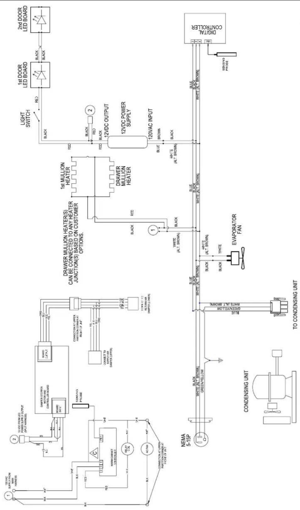
flowchart
graph TD
    A["122 VAC SUPPLY FROM MAIN HARNESS"] --> B["2"]
    B --> C["12 VDC FROM LED POWER SUPPLY OUTPUT (OUTPUT HARNESS)"]
    C --> D["BOARD INPUT"]
    D --> E["Sensing Probe"]
    E --> F["CONNECTION AT UPPER PARITION CORNER AT FRONT OF UNIT"]
    F --> G["CONNECT TO SUPPLY AIR DAMPER (UPPER)"]
    G --> H["1st MULLION HEATER"]
    H --> I["DRAWER MULLION HEATER(S) CAN BE CONNECTED TO ANY HEATER JUNCTION(S) BASED ON CUSTOMER OPTIONS."]
    I --> J["1st MULLION HEATER"]
    J --> K["12VDC OUTPUT"]
    K --> L["DRAWER MULLION HEATER"]
    L --> M["12VDC POWER SUPPLY"]
    M --> N["120VAC INPUT"]
    N --> O["BROWN"]
    O --> P["BLIC"]
    P --> Q["1"]
    Q --> R["BLACK"]
    R --> S["1"]
    S --> T["BLUE"]
    T --> U["BLIC"]
    U --> V["12VDC OUTPUT"]
    V --> W["BROWN"]
    W --> X["12VDC POWER SUPPLY"]
    X --> Y["BLIC"]
    Y --> Z["12VDC OUTPUT"]
    Z --> AA["BROWN"]
    AA --> AB["BLIC"]
    AB --> AC["12VDC OUTPUT"]
    AC --> AD["BLIC"]
    AD --> AE["12VDC OUTPUT"]
    AE --> AF["BLIC"]
    AF --> AG["12VDC OUTPUT"]
    AG --> AH["BLIC"]
    AH --> AI["12VDC OUTPUT"]
    AI --> AJ["BLIC"]
    AJ --> AK["12VDC OUTPUT"]
    AK --> AL["BLIC"]
    AL --> AM["12VDC OUTPUT"]
    AM --> AN["BLIC"]
    AN --> AO["12VDC OUTPUT"]
    AO --> AP["BLIC"]
    AP --> AQ["12VDC OUTPUT"]
    AQ --> AR["BLIC"]
    AR --> AS["12VDC OUTPUT"]
    AS --> AT["BLIC"]
    AT --> AU["12VDC OUTPUT"]
    AU --> AV["BLIC"]
PRODUCTION START: 04/20/2020
PRODUCTION END: NA
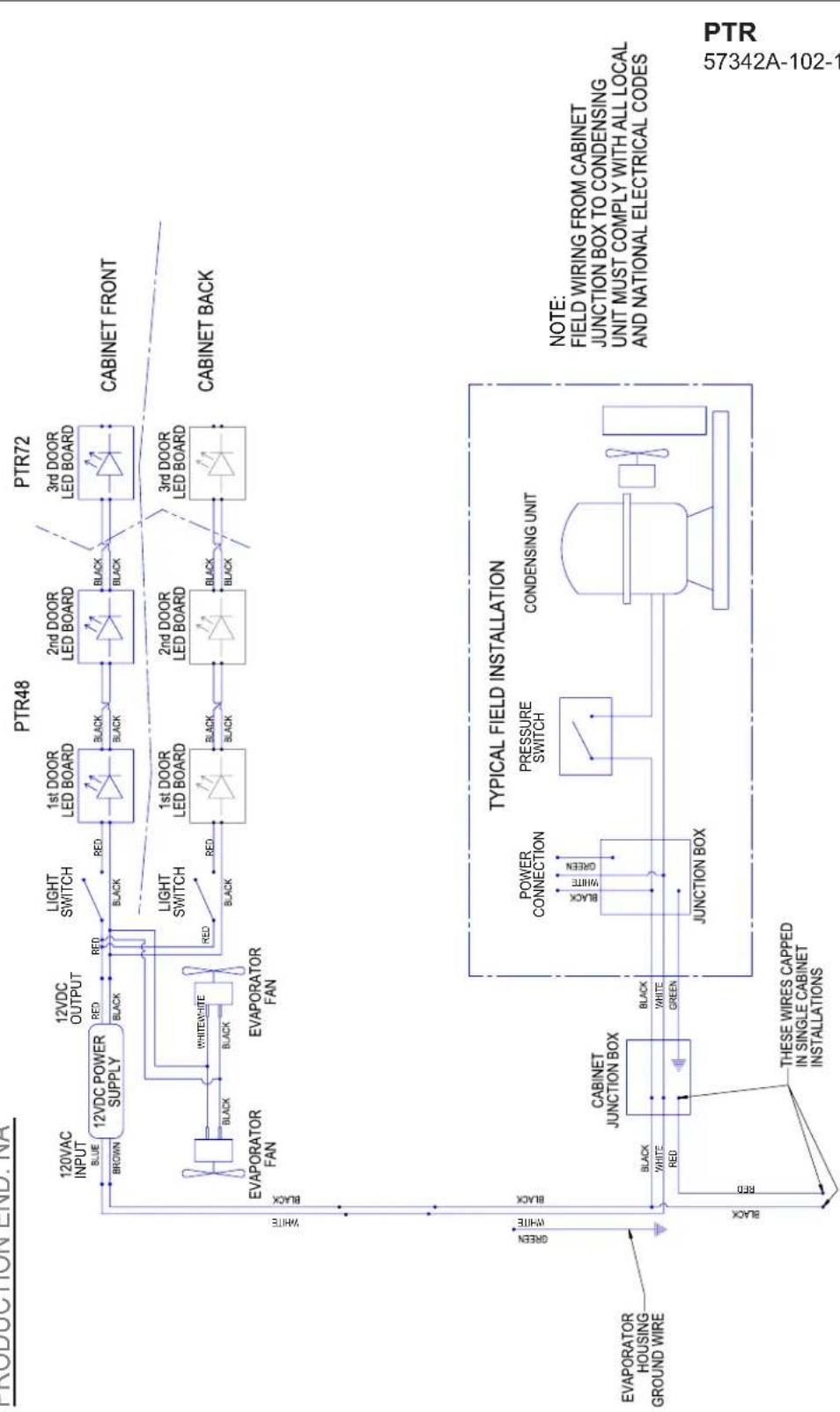
flowchart
graph TD
    A["Evaporator Fan"] -->|12VDC POWER SUPPLY| B["BROWN"]
    A -->|EVAPORATOR FAN| C["BLACK"]
    A -->|EVAPORATOR FAN| D["BLACK"]
    E["12VDC OUTPUT RED"] --> F["BLACK"]
    G["12VDC POWER SUPPLY"] --> H["BROWN"]
    G --> I["BLACK"]
    J["LIGHT SWITCH"] --> K["BLACK"]
    L["1st DOOR LED BOARD"] --> M["BLACK"]
    N["2nd DOOR LED BOARD"] --> O["BLACK"]
    P["3rd DOOR LED BOARD"] --> Q["BLACK"]
    R["TYPICAL FIELD INSTALLATION"] --> S["CABINET JUNCTION BOX"]
    T["POWER CONNECTION"] --> U["BLACK"]
    V["PRESSURE SWITCH"] --> W["GREEN"]
    X["CONDENSING UNIT"] --> Y["JUNCTION BOX"]
    Z["THESE WIRES CAPPED IN SINGLE CABINET INSTALLATIONS"] --> AA["BLACK"]
    AB["CABINET JUNCTION BOX"] --> AC["BLACK"]
    AD["TYPICAL FIELD INSTALLATION"] --> AE["CONDENSING UNIT"]
    AF["NOTE: FIELD WIRING FROM CABINET JUNCTION BOX TO CONDENSING UNIT MUST COMPLY WITH ALL LOCAL AND NATIONAL ELECTRICAL CODES"] --> AG["57342A-102-1"]

flowchart
graph TD
    A["NEMA 5-15P"] --> B["INVERTER"]
    B --> C["CONNECT CONDENSING UNIT HERE"]
    C --> D["MOLDED RECEPTACLE"]
    D --> E["CONDENSING UNIT PTS36 ONLY"]
    E --> F["CONDENSING PROBE"]
    F --> G["DIGITAL CONTROLLER"]
    G --> H["PTS 57342C-101-120"]
    I["PTS36"] --> J["Light SWITCH"]
    I --> K["Black"]
    I --> L["2nd DOOR LED BOARD"]
    I --> M["3rd DOOR LED BOARD"]
    I --> N["CABINET FRONT"]
    O["PTS60"] --> P["Black"]
    O --> Q["2nd DOOR LED BOARD"]
    O --> R["3rd DOOR LED BOARD"]
    S["PTS84"] --> T["Black"]
    S --> U["2nd DOOR LED BOARD"]
    S --> V["CABINET BACK"]
    W["12VDC POWER SUPPLY"] --> X["12VDC OUTPUT"]
    Y["120VAC INPUT BROWN"] --> Z["BLUE"]
    AA["WHITE"] --> AB["BLANK"]
    AC["BLACK"] --> AD["BLACK"]
    AE["EVAPORATOR FAN"] --> AF["WHITE"]
    AG["RED"] --> AH["BLACK"]
    AI["RED"] --> AJ["BLACK"]
    AK["RED"] --> AL["BLACK"]
    AM["Sensing Probe"] --> AN["Digital Controller"]
    AO["DISCONNECT WHEN SERVICING"] --> AP["CONDENSING UNIT PTS60 & PTS84 MODELS"]
    AP --> AQ["MOLDED RECEPTACLE"]

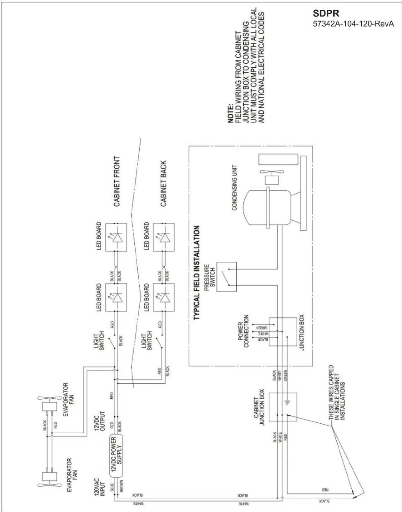
flowchart
graph TD
    A["120VAC INPUT BLUE"] --> B["12VDC POWER SUPPLY"]
    B --> C["12VDC OUTPUT RED"]
    C --> D["12VDC OUT"]
    D --> E["BROWN"]
    F["EVAPORATOR FAN"] --> G["Black"]
    H["EVAPORATOR FAN"] --> I["Black"]
    J["LED BOARD"] --> K["Black"]
    L["LED BOARD"] --> M["Black"]
    N["LED BOARD"] --> O["Black"]
    P["SDBR48"] --> Q["Light SWITCH"]
    Q --> R["Black"]
    S["SDBR96"] --> T["LED BOARD"]
    T --> U["Black"]
    V["TYPICAL FIELD INSTALLATION"] --> W["CABINET JUNCTION BOX"]
    W --> X["POWER CONNECTION"]
    X --> Y["PRESSURE SWITCH"]
    Y --> Z["JUNCTION BOX"]
    AA["CONDENSING UNIT"] --> AB["CONDENSING UNIT"]
    AC["NOTE: FIELD WIRING FROM CABINET JUNCTION BOX TO CONDENSING UNIT MUST COMPLY WITH ALL LOCAL AND NATIONAL ELECTRICAL CODES"] --> AD["SDBR48-SDBR 57342A-106-120-F"]
    AE["THESE WIRES CAPPED IN SINGLE CABINET INSTALLATIONS"] --> AF["RED"]

flowchart
graph TD
    A["NEMA 5-15P"] --> B["TO CONDENSING UNIT"]
    B --> C["EVAPORATOR FAN"]
    C --> D["12VDC OUTPUT"]
    D --> E["12VDC POWER SUPPLY"]
    E --> F["LED BOARD"]
    F --> G["SDBS60"]
    F --> H["SDBS108"]
    F --> I["PLUGGED"]
    I --> J["Digital CONTROLLER"]
    J --> K["SENSING PROBE"]
    K --> L["BLUE BLACK WHITE (ALT. BROWN)"]
    L --> M["BLACK"]
    M --> N["Black"]
    N --> O["LED BOARD"]
    O --> P["SDBS60"]
    O --> Q["SDBS108"]
flowchart
graph TD
    A["Evaporator Fan"] -->|BLACK RED| B["EVAPORATOR FAN"]
    B --> C["12VDC POWER SUPPLY"]
    C -->|BLUE BROWN| D["12VDC OUTPUT"]
    D --> E["LIGHT SWITCH"]
    E --> F["LED BOARD"]
    F --> G["CABINET FRONT"]
    G --> H["CABINET BACK"]
    H --> I["TYPICAL FIELD INSTALLATION"]
    I --> J["PRESSURE SWITCH"]
    J --> K["CONDENSING UNIT"]
    K --> L["JUNCTION BOX"]
    L --> M["CABINET JUNCTION BOX"]
    M --> N["THESE WIRES CAPPED IN SINGLE CABINET INSTALLATIONS"]
    style A fill:#f9f,stroke:#333
    style B fill:#f9f,stroke:#333
    style C fill:#ccf,stroke:#333
    style D fill:#ccf,stroke:#333
    style E fill:#cfc,stroke:#333
    style F fill:#fcc,stroke:#333
    style G fill:#fcc,stroke:#333
    style H fill:#fcc,stroke:#333
    style I fill:#ffc,stroke:#333
    style J fill:#ffc,stroke:#333
    style K fill:#ffc,stroke:#333
    style L fill:#ffc,stroke:#333
    style M fill:#ffc,stroke:#333
    style N fill:#ffc,stroke:#333
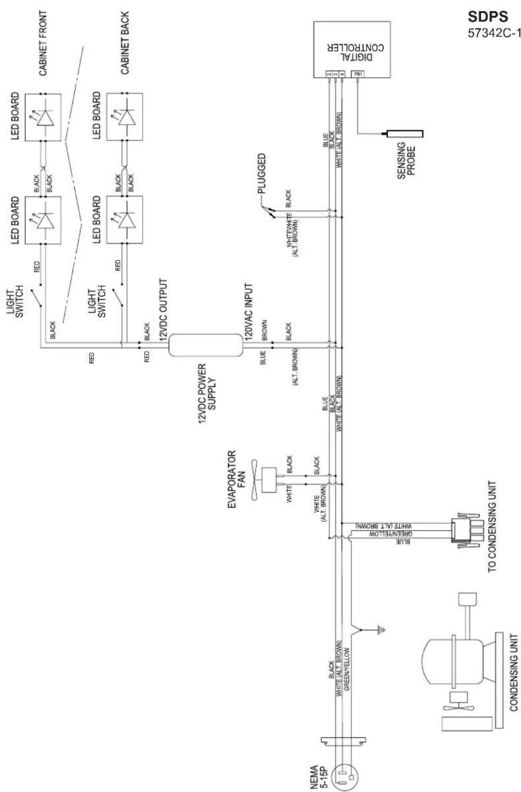
flowchart
graph TD
    A["NEMA 5-15P"] --> B["CONDENSING UNIT"]
    B --> C["TO CONDENSING UNIT"]
    C --> D["EVAPORATOR FAN"]
    D --> E["12VDC POWER SUPPLY"]
    E --> F["12VAC INPUT"]
    F --> G["PLUGGED"]
    G --> H["Digital CONTROLLER"]
    H --> I["SENSING PROBE"]
    I --> J["WHITE (ALT. BROWN)"]
    J --> K["GREEN/YELLOW"]
    K --> L["WHITE (ALT. BROWN)"]
    L --> M["BLACK"]
    M --> N["Black"]
    N --> O["LED BOARD"]
    O --> P["CABINET FRONT"]
    O --> Q["CABINET BACK"]
    O --> R["RED"]
    R --> S["LED BOARD"]
    S --> T["BLACK"]
    T --> U["LED BOARD"]
    U --> V["BLACK"]
    V --> W["LED BOARD"]
    W --> X["BLACK"]
    X --> Y["LED BOARD"]
    Y --> Z["BLACK"]
    Z --> AA["LED BOARD"]
    AA --> AB["BLACK"]
    AB --> AC["LED BOARD"]
    AC --> AD["BLACK"]
    AD --> AE["LED BOARD"]
    AE --> AF["BLACK"]
    AF --> AG["LED BOARD"]
    AG --> AH["BLACK"]
    AH --> AI["LED BOARD"]
    AI --> AJ["BLACK"]
    AJ --> AK["LED BOARD"]
    AK --> AL["BLACK"]
    AL --> AM["LED BOARD"]
    AM --> AN["BLACK"]
    AN --> AO["LED BOARD"]
WARRANTY
The terms and conditions set forth below together with those appearing on the face of the Acknowledgement (the “Order”) constitute the complete and exclusive agreement between Perlick Corporation and the Buyer pertaining to the goods and/or services identified in the Order. If there is a discrepancy or conflict between any exhibit or supplement to the Order and these terms and conditions, these terms and conditions shall control. The Order is intended by Seller and Buyer to be the complete, exclusive, and final statement of their agreement. Any changes to an Order must be in writing and signed by Perlick and Buyer.
TERMS NET 30 DAYS
Payment by Visa, MasterCard, American Express or Discover card accepted or cash in advance unless prior accommodations have been made with our Credit Department. Please direct inquiries for detailed information to our Credit Manager. All sales, excise, or similar taxes required by law to be collected or paid by seller shall be in addition to prices quoted unless an appropriate Tax Exemption certificate is furnished. All goods are sold F.O.B. factory. Except for otherwise provided, Perlick will not be responsible for freight, transportation, insurance, shipping, storage, handling, demurrage or similar charges. Invoices are payable in full in thirty (30) days following the invoice,s date of issuance. If by the terms of sale credit is extended, Perlick reserves the right to revoke such credit if buyer fails to pay for any products when due and may demand payment prior to the commencement of any further shipment.
WAIVER
Any waiver of strict compliance with the provisions of an Order must be in writing. No such waiver shall be construed as a waiver of any other term or condition except as provided in writing, nor as a waiver of any subsequent breach of the same term or condition.
METHOD OF SHIPMENT
All shipments are carefully packed and labeled. Crates, boxes and cartons used are of approved weight and strength. Freight rates are based upon 100 pound minimum.
LOST and DAMAGED MERCHANDISE
THE RESPONSIBILITY OF THE PERLICK CORPORATION CEASES UPON ACCEPTANCE OF ITS PRODUCTS BY THE CARRIER. Any damage or loss sustained in shipment is the carrier's responsibility. Before giving the carrier a clean receipt at time of delivery, make sure you receive every item on the bill and inspect every carton, crate and box for concealed damage, i.e., broken boards, crushed or punctured cartons, torn cardboard. IF ANY ITEMS ARE SHORT OR DAMAGED, DO NOT ACCEPT THE SHIPMENT UNLESS THE CARRIER MAKES A NOTATION OF THIS ON YOUR FREIGHT BILL. Then request an inspection. Do not destroy the packing materials. If their agent does not make an inspection within five days, advise the carrier via letter that you notified them regarding the matter and they have failed to act. You will need this letter to support your claim. Then file a claim for your loss. When you give the carrier a clean receipt, you accept the total responsibility for the shipment. UPS shipments are insured individually and UPS will replace all merchandise that is lost or damaged.
RETURN OF MERCHANDISE
Do not return any merchandise without our approval. Merchandise returned without a return merchandise authorization number will not be accepted at Perlick. Used, discontinued, and certain custom made items cannot be returned for credit. These custom items include non-catalog products (specials) as well as custom assembled catalog products. Catalog items are designated as non-returnable on the price list page on which they appear. Items returned must be in new condition and packaged in their original carton or crate. Freight charges must be prepaid on all return shipments.
When a return is authorized, a credit may be allowed pending an examination of the returned goods. The amount of the restocking charge will depend on the condition of the equipment. The minimum restocking charge for glass washers, bottle coolers, frosters, direct draws, cooler series back bars and accessory parts is 20%. The minimum restocking charge for custom series cabinets is 50%. The minimum restocking charge for un-assembled, freestanding underbar stainless steel modules is 20%. Assembled under bar modules are considered custom products and are not returnable for credit. The restocking charge on the item returned is either a percentage of the value of the item or \$35.00, whichever is greater.
ONE YEAR PARTS WARRANTY
Perlick products are guaranteed against defects in both material and workmanship for a period of one year from date of sale. Defective parts will be replaced on a no-charge basis, F.O.B. our factory, when adjudged defective upon inspection. We are not responsible for parts damaged by alteration, unauthorized service, accident or abuse. All costs associated with replacement, including freight, labor and/or loss of sales, are the responsibility of the user.
ONE YEAR LABOR WARRANTY
In addition to Perlick's one year parts warranty and five year compressor warranty, ALL PERLICK REFRIGERATION SYSTEMS are offered with a one year labor warranty at no extra charge. Perlick's one year labor warranty provides that Perlick will pay for the cost of any labor to replace any defective part for up to one year after installation, subject to the following terms and conditions:
(A) Parts returned to Perlick shall be returned freight prepaid and shall be identified with Perlick's serial number and return authorization number.
(B) Improper operation due to voltage variances, inadequate wiring and physical damage is the responsibility of the purchaser. They are not manufacturing defects.
(C) Condenser coils shall be cleaned regularly. Failure to provide an adequate flow of cooling air will void this warranty.
(D) Factory-specified maintenance and installation will be provided by the selling dealer who shall also be responsible for the installation and set-up of these products in accordance with local plumbing, refrigeration and electrical codes.
Perlick's one year labor policy applies to the United States and Canada. IT DOES NOT APPLY TO REFRIGERATION SYSTEMS ADDED BY OTHERS (remote systems) or any part which has been subject to misuse, neglect, alteration, accident, or to any damage caused by transportation, flood, fire or other acts of God.
NOTES
NOTES

text_image
Perlick®Form No. Z2604
Rev A 06.27.2022
Z2604