
KAMMTARTCBA - Stair Ramp Aid Kogan - Free user manual and instructions
Find the device manual for free KAMMTARTCBA Kogan in PDF.

| Product Type | Articulating Monitor Mount with Laptop Holder |
| Brand | Kogan |
| Model | KAMMTARTCBA |
| VESA Compatibility | 75mm x 75mm, 100mm x 100mm |
| Monitor Size Range | 17" - 32" |
| Installation Options | C-Clamp (desk clamp) or Grommet Base Plate |
| Number of Articulating Arms | 2 |
| Tilt Adjustment | Yes (via Allen key) |
| Swivel Adjustment | Yes (manual) |
| Rotation Adjustment | Yes (manual) |
| Laptop Tray Included | Yes |
| Cable Management | Yes (wire clips on pole and arms) |
| Security Feature | Security nut to prevent accidental adjustments |
| Included Tools | Allen keys (3mm and 5mm), wrench |
| Hardware Kit | M5x14, M8x12, M4x12, M4x30 bolts; M4 spacers; D4 nuts; security nut |
| Grommet Hole Diameter Required | 10mm (for self-drilled installation) |
| Material | Steel (assumed) |
| Color | Black (assumed) |
| Weight Capacity | Not specified; ensure not exceeded |
| Customer Support | help.Kogan.com |
Frequently Asked Questions - KAMMTARTCBA Kogan
User questions about KAMMTARTCBA Kogan
0 question about this device. Answer the ones you know or ask your own.
Ask a new question about this device
Download the instructions for your Stair Ramp Aid in PDF format for free! Find your manual KAMMTARTCBA - Kogan and take your electronic device back in hand. On this page are published all the documents necessary for the use of your device. KAMMTARTCBA by Kogan.
USER MANUAL KAMMTARTCBA Kogan
natural_image
Technical line drawing of a mechanical assembly with vertical supports and a horizontal platform (no text or symbols)ARTICULATING MONITOR MOUNT WITH LAPTOP HOLDER
17" - 32"
KAMMTARTCBA
SAFETY & WARNINGS
- If you do not understand these directions or if you have any doubts about the safety of the installation, please contact a qualified technician.
- Ensure that you have received all parts according to the component checklist prior to installation. If any parts are missing or faulty, contact help.Kogan.com for support.
- Closely follow the assembly instructions. Improper installation may result in property damage or serious personal injury.
- Do not use this product for any purpose that is not explicitly specified in this guide.
- Do not exceed weight capacity.
-
Serious or fatal injuries can occur from tip over. To prevent tip over:
-
Never allow children to climb, stand, hang or play on any part or monitor or stand.
- Use tip over restraint or anchor stand to wall.
VESA Compatible
75×75
100×100

COMPONENTS

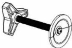
A Pole
B C-Clamp

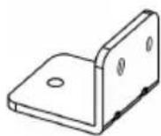
C C-Clamp Brace

D Swivel Arm (x2)

E VESA Plate (x2)
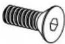
F M5x14 Bolt (x3)
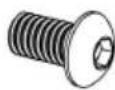
G M8x12 Bolt (x2)
H Security Nut (x2)
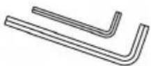
I Allen Key
J M4x12 Bolt (x8)
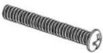
J M4x30 Bolt (x8)
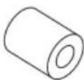
L M4 Spacer (x8)
natural_image
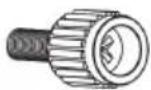
Technical line drawing of a mechanical lever assembly (no text or symbols)M M10 Hand Knob

N EVA Pad A

EVA Pad B
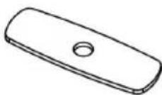
P Support Plate

Q Base Plate

R Laptop Tray

S M4x12 Bolt (x4)

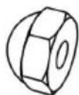
T D4 Nut (x4)

U Anti-skid Pad (x4)
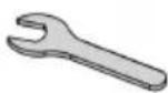
V Wrench

W Wire Clip (x2)
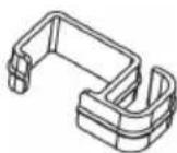
X Wire Clip (x3)
INSTALLATION
Clamp Installation
-
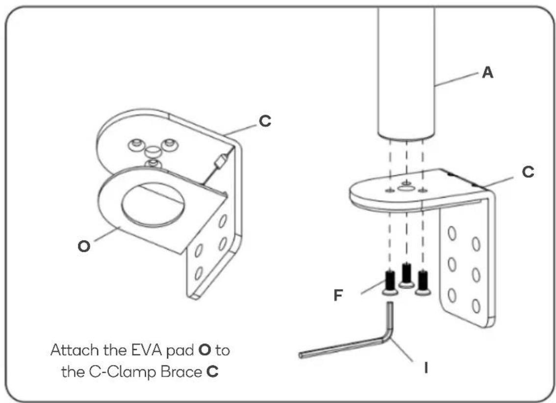
Connect Pole (A) and C-Clamp Brace (C) from the bottom using x3 M5x14 bolts (F) and tighten using the Allen Key 3mm (I).
-
Attach the EVA pad (O) to the C-Clamp Brace (C).
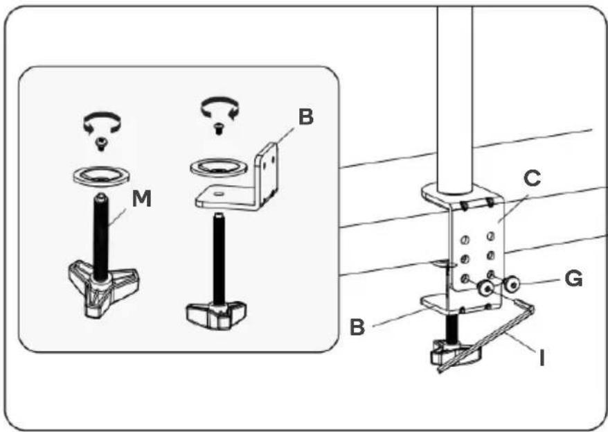
- Unscrew the screw and washer from the M10 hand knob (M) to remove the top plate. Connect the C-clamp (B) to the M10 hand knob (M) and reattach the top plate by fastening the screw and washer.
Connect the C-clamp (B) to the C-clamp brace (C) using x2 M8x12 bolts (G) and tighten using the Allen key (5mm) (I).
Turn the M10 hand knob (M) clockwise to fasten.
Base Plate Installation
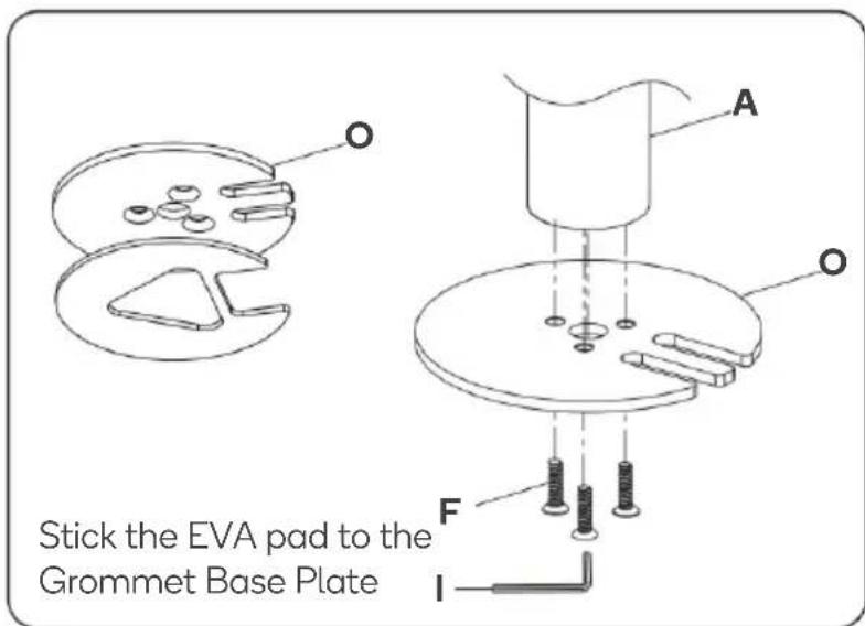
Place the pole (A) onto the grommet base plate (O). Connect them from the bottom using x3 M5x14 bolts (F) and tighten with the Allen key (3mm) (I).
Existing Grommet Hole Installation
- If the existing grommet hole comes with a plastic protector, remove it.
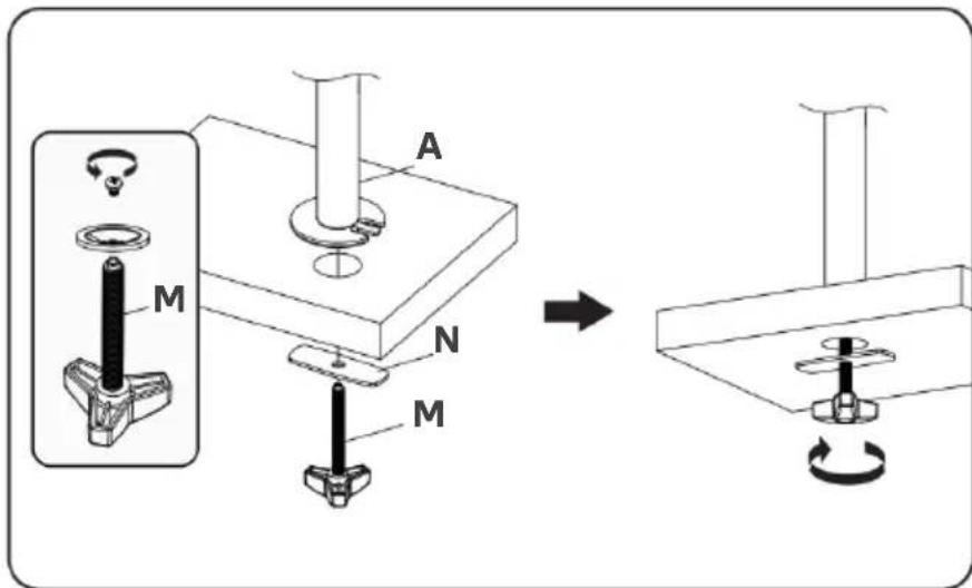
- Unscrew the screw and washer from the M10 hand knob (M) to remove the top plate. Store the screw, washer and top plate safely.
- Thread the support plate (Q) through the M10 hand knob (M). Position the grommet base plate assembly over the grommet hole. Insert the M10 hand knob (M) into the grommet hole and into the pole (A) and turn the M10 hand knob (M) clockwise to secure.
Self-drilled Grommet Hole Installation
- Mark the position of the hole on your desk and drill a 10mm diameter hole at the marked position.
- Unscrew the screw and washer from the M10 hand knob (M) to remove the top plate. Store the screw, washer and top plate safely.
- Thread the support plate (P) through the M10 hand knob (M). Position the grommet base plate assembly over the grommet hole. Insert the M10 hand knob (M) into the grommet hole and into the pole (A) and turn the M10 hand knob (M) clockwise to secure.

Assemble the Swivel Arms
- Slide the 2 wire clips (W) and 2 swivel arms (D) onto the pole (A).
- Adjust to the preferred heights and tighten using the Allen Key 5mm (I).
- Attach the 3 wire clips (X) to the swivel arms (D).

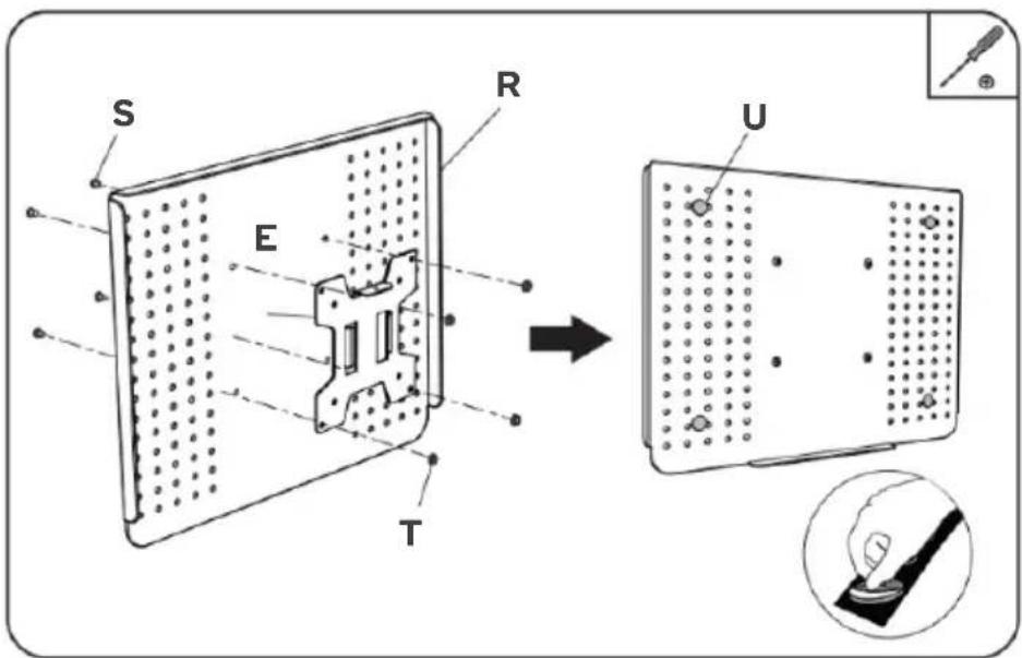
Laptop Tray Installation
- Attach the VESA plate (E) to the laptop tray (R) using x4 M4x12 bolts (S) and x4 D4 nuts (T), then tighten with a screwdriver (not supplied).
- Place the anti-skid pads (U) in the designated position on the tray, as shown below.
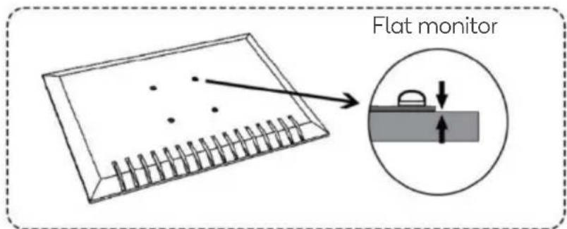
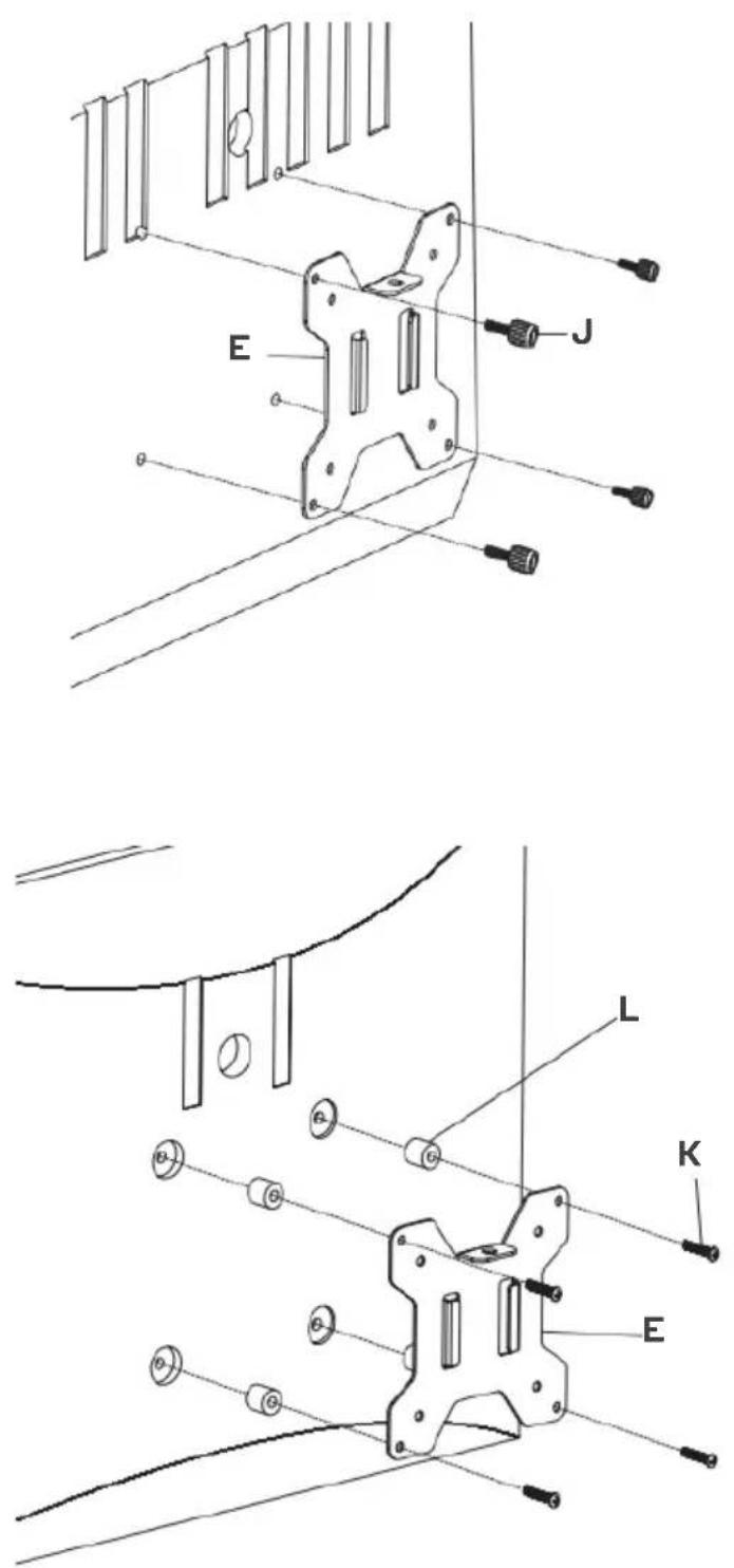
Attach the VESA Plate to the Monitor
- Select the bolts that fit your monitor (M4x12 (J) or M4x30 (K)). Insert the bolts into the holes on the back of the monitor to determine which size bolt suits your monitor.


natural_image
Hand drawing on a notepad with a pen and spiral notebook (no text or symbols)- If you have a curved monitor or one with recessed VESA holes, you will need to use x4 M4 spacers (L).

Note: Spacers are not required for flat monitors.
- Insert the x4 M4 spacers (L) (if required) and the x4 bolts selected in step 1 ((J) or (K)) through the VESA plate (E) and into the monitor and tighten with a screwdriver (not provided).
Install the Laptop Tray
-
Place the assembled laptop tray onto the swivel arm (D) and install the security nut (H) as shown. Note: Ensure the security nut is installed before adjusting the monitor or laptop.
-
Tighten the security nut (H) using the wrench (V).

-
Route the cables through the Wire Clips (W, X) and store the Allen Keys (I) in the wire clip (W).
-
Adjust the tilt angle using the Allen Key 5mm (I).

- Manually swivel, tilt and rotate the laptop tray to achieve the best viewing angle.
Note: Ensure the security nut is installed before adjusting the monitor or laptop. Always remove your laptop before making any adjustments.

Need more information?
We hope that this user guide has given you the assistance needed for a simple set-up.
For the most up-to-date guide for your product, as well as any additional assistance you may require, head online to help.kogan.com
kogan.com
- ARTICULATING MONITOR MOUNT WITH LAPTOP HOLDER
- SAFETY & WARNINGS
- COMPONENTS
- INSTALLATION
- Clamp Installation
- Base Plate Installation
- Existing Grommet Hole Installation
- Self-drilled Grommet Hole Installation
- Assemble the Swivel Arms
- Laptop Tray Installation
- Attach the VESA Plate to the Monitor
- Install the Laptop Tray
- Need more information?
Brand : Kogan
Model : KAMMTARTCBA
Category : Stair Ramp Aid