SBP20KRMI4U - Inverter APC - Free user manual and instructions
Find the device manual for free SBP20KRMI4U APC in PDF.

User questions about SBP20KRMI4U APC
0 question about this device. Answer the ones you know or ask your own.
Ask a new question about this device
Download the instructions for your Inverter in PDF format for free! Find your manual SBP20KRMI4U - APC and take your electronic device back in hand. On this page are published all the documents necessary for the use of your device. SBP20KRMI4U by APC.
USER MANUAL SBP20KRMI4U APC
Installation and Operation
Service Bypass Panel
SBP20KP
SBP20KRMT4U
SBP20KRMI4U
text_image
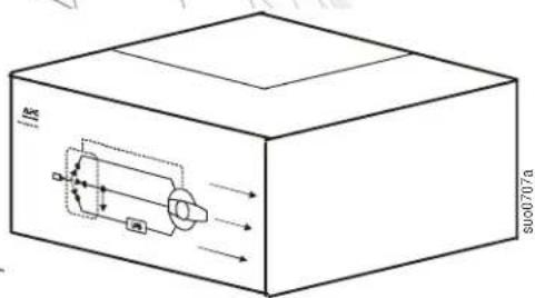
E 000707aThis manual and the safety guide are available in English on the enclosed CD and the APC Web site, www.apc.com.
The APC ^® by Schneider Electric service bypass panel (SBP), provides utility power to connected equipment during UPS maintenance.
Inventory
Read the Safety Guide before installing the UPS.
Inspect the SBP upon receipt. Notify the carrier and dealer if there is damage.
The package is recyclable; save it for reuse or dispose of it properly.

natural_image
Simple line drawing of a box with a small inset image on the side (no text or symbols)Literature Kit:
• Product documentation
- Safety Guide
- Warranty card
- Allen wrench

(1)

Rail Kit Installation Kit

Installation Kit Contents
 (8) (8) |  (8) (8) |  (8)(2) (8)(2) |  |
 (1 pair) (1 pair) |  (1 pair) (1 pair) |  (1 pair) (1 pair) |  (1 pair) (1 pair) |
Specifications
Electrical Specifications
| SBP model Rated Input Voltage Rated Output Voltage | Input Current maximum | Output Power Watts/VA maximum | ||
| SBP20KP | 200/208/240 VAC50/60 Hz, 2P+PE | 200/208/240 VAC50/60 Hz, 2P+PE | 125 A each phase | 30,000 |
| 220/230/240 VAC50/60 Hz 1P+N+PE | 220/230/240 VAC50/60 Hz, 1P+N+PE | 125 A each phase | 30,000 | |
| 380/400/415 VAC50/60 Hz, 3P+N+PE | 220/230/240 VAC50/60 Hz, 1P+N+PE | 125 A each phase | 30,000 | |
| SBP20KRMT4U | 200/208/240 VAC50/60 Hz, 2P+PE | 200/208/240 VAC50/60 Hz, 2P+PE | 125 A each phase | 30,000 |
| SBP20KRMI4U | 220/230/240 VAC50/60 Hz, 1P+N+PE | 220/230/240 VAC50/60 Hz, 1P+N+PE | 125 A each phase | 30,000 |
| 380/400/415 VAC50/60 Hz, 3P+N+PE | 220/230/240 VAC50/60 Hz, 3P+N+PE | 125 A each phase | 30,000 | |

Note: The table above represents the electrical ratings of the SBP and not those of the UPS. UPS wire specifications may vary. The SBP requires a minimum wire size of 25 mm^2 and a maximum wire size of 50 mm^2 . Refer to the UPS user manual for UPS wiring specifications.
SBP ratings must be equal to or greater than those of the UPS to which it is connected.
The input circuit breaker should not exceed the rating recommended on the UPS.
The system load must not exceed the electrical rating of the UPS. For example, if a 3840 VA SBP is used with a 3000 VA UPS the maximum load that the system will support is 3000 VA.
Environmental Specifications
| Temperature | Operating 0° to 40°C (32° to 104°F) This unit is intended for indoor use only. | |
| Storage -15° to 45°C (-40° to 113°F) | Do not operate the service bypass panel where there is excessive dust or the temperature or humidity are outside specified limits. | |
| Maximum Elevation | Operating 3,000 m (10,000 ft) | Be sure the air vents on the SBP are not blocked. Allow adequate space for proper ventilation. |
| Storage 15,000 m (50,000 ft) | ||
| Humidity 0 to 95% relative humidity, non-condensing | ||

Changes and modifications to this unit not expressly approved by APC could void the warranty.
Front panel
flowchart
graph LR
    A["AC Input"] --> B["AC"]
    B --> C["Test"]
    C --> D["UPS"]
    D --> E["Load not protected"]
    E --> F["Normal"]
    F --> G["Load protected"]
    G --> H["Bypass"]
    H --> I["Load not protected"]
    I --> J["Bypass"]
    J --> K["Load not protected"]
Rear panels
Callout Description
| 1 | Equipment outlets |
| 2 | Equipment outlet circuit breakers |
| 3 | Utility input power hardwire access |
| 4 | Output power hardwire access |
SBP20KRMI4U SBP20KRMT4U

text_image
1 2 1 2 3 suo0687a 2 1 2 1 2 1 suo0686aSBP20KP

text_image
4 suo0688a 3Installation
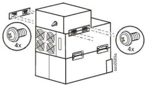
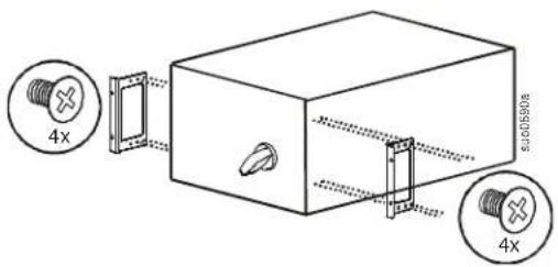
Stack configuration
Always place the SBP above the external battery packs and the UPS.
Four ornamental screws (supplied), must be used to secure each tie bracket to the units, (see diagram).
text_image
4x 4x 000689aRack-mount configuration
Install rails in rack
For details on rail installation refer to the instructions included in the rail kit.
Install rack-mount brackets
Secure the brackets to the unit using eight flat head screws (supplied).
text_image
4x 4xInstall cleats
Secure the cleats to the unit using eight Pan head screws (supplied).

text_image
4x su0698a 4xInstall in rack
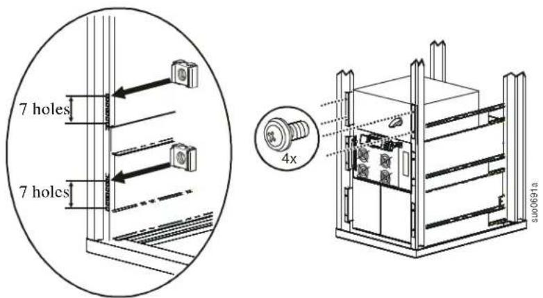
Always place the SBP above the external battery packs and the UPS.
A cage nut and an ornamental screw (supplied), must be used in the top hole of each rack-mount bracket when securing the unit in the rack.
The bottom hole of each rack-mount bracket must be secured using an ornamental screw (supplied), in the threaded hole.
text_image
7 holes 7 holes 4x S100691aWall-mount configuration
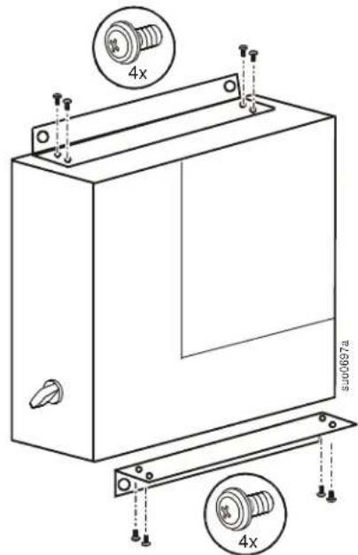
Secure the wall-mount brackets to the unit using eight ornamental screws (supplied), four in each bracket.
Secure the SBP to the wall. Select screws (not supplied), that are appropriate for the weight of the unit and the mounting surface material.
text_image
4x SU00697a 4xHardwire the SBP
Hardwiring must be performed by a qualified electrician.
Adhere to all national and local electrical codes.
Switch the utility circuit breaker off.
| Remove the terminal block access panel located on top of the unit. | 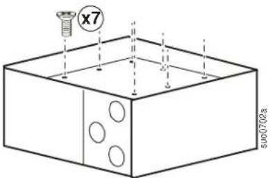 | |
| On all models, remove the access panel with three knockout pieces.Remove all three knockout pieces from the panel. |  | |
| Model SBP20KP has two access panels. Remove both of the access panels.Remove all three knockout pieces from the small panel.Remove one of the knockout pieces from the large panel. | 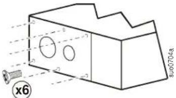 | |
| Strip 24 mm (1 inch), of insulation from the cable ends. |  | |
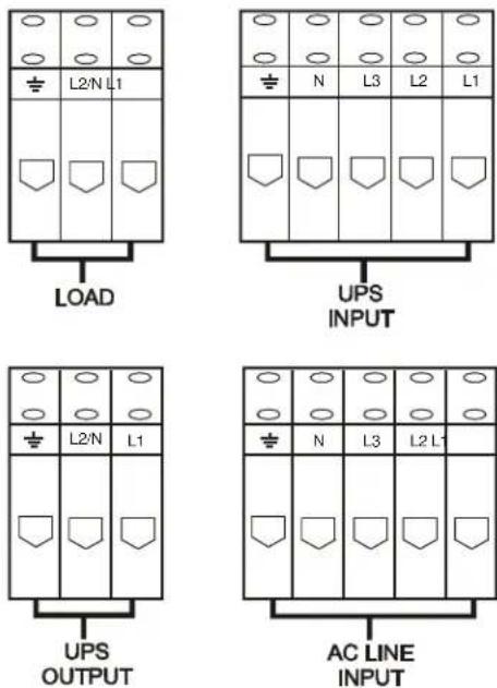
| Insert cables through the holes in the access panel(s). Connect the ground terminal first.Install an appropriate strain relief (not supplied), on each cable.Secure the cables in the terminal blocks. Refer to the terminal block configurations on the following page.Use the Allen wrench supplied to tighten the terminal block screws.Torque terminals to 6 Nm (53 in-lb) minimum, 8 Nm (71 in-lb) maximum.Replace the access panel(s) using all of the screws removed in the previous steps. Failure to do so may result in personal injury or equipment damage. |  | 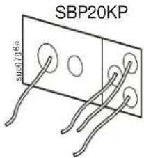 |
SBP20KRMI4U SBP20KRMT4U
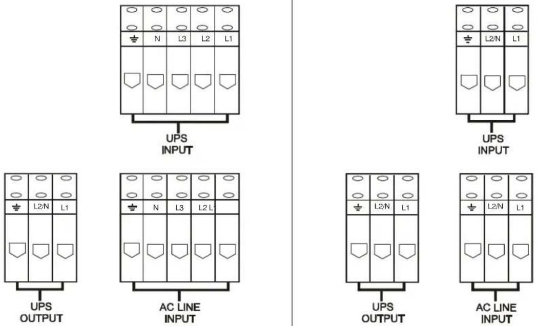
SBP20KP
Hardwire the UPS
Refer to the UPS user manual for detailed instructions.
Operation
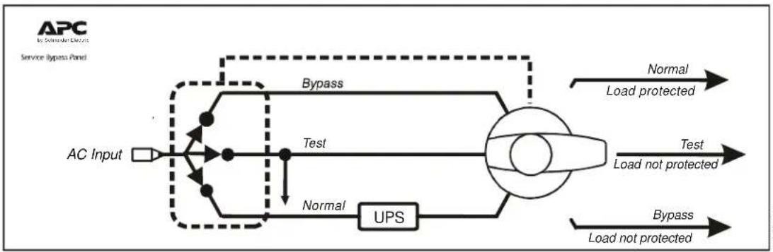
Normal mode
While the SBP operates in normal mode, power is supplied to connected equipment from the UPS providing protection from power variations and disturbances.
Test mode
-
Switch the UPS to Bypass mode. Verify that no UPS fault conditions exist. In the event that a fault condition exists, refer to the user manuals for the UPS and SBP.
-
Switch the SBP to Test mode.

Note: While the SBP is in Test mode connected equipment receives direct utility power and is not protected by the UPS.
The UPS will continue to receive input utility power. The Equipment Protection Policy is not valid while the SBP is operating in Test mode.
Bypass mode
Bypass mode enables connected equipment to operate on utility power while UPS maintenance is performed.
While in SBP Bypass mode the UPS will not receive utility input power. The UPS will receive battery power while in SBP Bypass mode. Refer to the UPS user manual for shutdown procedures.

Note: Connected equipment is not protected by the UPS while the SBP is in Bypass mode. The Equipment Protection Policy is not valid while the SBP is operating in Bypass mode.
Reconnect SBP to UPS
Bypass mode
- Put the SBP in Bypass mode.
- Correctly configure the input, output and battery connections on the UPS. DO NOT turn on the UPS at this time.
Test mode
-
Switch the SBP to Test mode.
a. The connected equipment will receive direct input utility power.
b. The UPS will receive input utility power. -
Verify that no UPS fault conditions exist. In the event that a fault condition exists, refer to the user manuals for the UPS and SBP.
-
Turn on the UPS output power.
Normal mode
- Switch the UPS to Bypass mode. Verify that no UPS fault conditions exist. In the event that a fault condition exists, refer to the user manuals for the UPS and SBP.
- Switch the SBP to Normal mode.
- Switch the UPS to Online mode. Verify that no UPS fault conditions exist. In the event that a fault condition exists, refer to the user manuals for the UPS and SBP.
The SBP will now supply power to connected equipment from the UPS providing protection from power variations and disturbances.
Troubleshooting
Use the table to solve minor installation and operation problems.
Refer to the APC Web site, www.apc.com for assistance with complex problems.
| Problem and/or Possible Cause Solution | |
| UPS will not turn on | |
| SBP is in Bypass mode. | Rotate the SBP switch to TEST. |
| There is no power at the UPS input. Verify that | the power cables from the SBP to the utility power, and from the SBP to the UPS input are securely connected. |
| UPS is faulty or damaged. | Rotate the SBP switch to Test. If the connected equipment is energized, the UPS may be faulty. Refer to Troubleshooting in the UPS user manual for detailed information. |
| There is no power at the utility power outlet. | Rotate the SBP switch to Test. If the connected equipment does not become energized, the utility power outlet may be faulty. Verify the utility power supply. Contact a qualified electrician to check the building electrical power. |
| UPS is Online; not providing power to connected equipment | |
| SBP output circuit breaker has tripped. Disconnect all nonessential equipment from the SBP. Reset the SBP circuit breaker. | |
| There is no SBP output power. | Verify that the power cable from the SBP to the UPS output is securely connected. |
Contact information
Customer support for this or any other APC product is available at no charge in any of the following ways: Visit the APC Web site to access documents in the APC Knowledge Base and to submit customer support requests.
- www.apc.com (Corporate Headquarters)
Connect to localized APC Web sites for specific countries, each of which provides customer support information.
- www.apc.com/support/
Global support searching APC Knowledge Base and using e-support.
- Contact the APC Customer Support Center by telephone (888) 272 2782, or by e-mail.
Local, country-specific centers: go to www.apc.com/support/contact for contact information. For information on how to obtain local customer support, contact the APC representative or other distributors from whom you purchased your APC product.
Service
If the unit requires service, do not return it to the dealer. Follow these steps:
- Review the Troubleshooting section of the manual to eliminate common problems.
-
If the problem persists, contact APC Customer Support through the APC Web site, www.apc.com.
a. Note the model number and serial number and the date of purchase. The model and serial numbers are located on the rear panel of the unit and are available through the LCD display on select models.
b. Call APC Customer Support and a technician will attempt to solve the problem over the phone. If this is not possible, the technician will issue a Returned Material Authorization Number (RMA#).
c. If the unit is under warranty, the repairs are free.
d. Service procedures and returns may vary internationally. Refer to the APC Web site for country specific instructions. -
Pack the unit in its original packaging. If this is not available, refer to www.apc.com to obtain a new set.
a. Pack the unit properly to avoid damage in transit. Never use foam beads for packaging. Damage sustained in transit is not covered under warranty.
b. For the UPS, always DISCONNECT THE BATTERY before shipping in compliance with U.S. Department of Transportation (DOT) and IATA regulations. The battery may remain in the unit.
c. Internal batteries may remain connected in the XLBP during shipment, (if applicable, not all units have XLBPs).
-
Write the RMA# provided by Customer Support on the outside of the package.
-
Return the unit by insured, pre-paid carrier to the address provided by Customer Support.
Transport the unit
- Shut down and disconnect all connected equipment.
- Disconnect the unit from utility power.
- Disconnect all internal and external batteries (if applicable).
- Follow the shipping instructions outlined in the Service section of this manual.
Two-Year Factory Warranty
This warranty applies only to the products you purchase for your use in accordance with this manual.
Terms of warranty
APC warrants its products to be free from defects in materials and workmanship for a period of two years from the date of purchase. APC will repair or replace defective products covered by this warranty. This warranty does not apply to equipment that has been damaged by accident, negligence or misapplication or has been altered or modified in any way. Repair or replacement of a defective product or part thereof does not extend the original warranty period. Any parts furnished under this warranty may be new or factory-remanufactured.
Non-transferable warranty
This warranty extends only to the original purchaser who must have properly registered the product. The product may be registered at the APC Web site, www.apc.com.
Exclusions
APC shall not be liable under the warranty if its testing and examination disclose that the alleged defect in the product does not exist or was caused by end user's or any third person's misuse, negligence, improper installation or testing. Further, APC shall not be liable under the warranty for unauthorized attempts to repair or modify wrong or inadequate electrical voltage or connection, inappropriate on-site operation conditions, corrosive atmosphere, repair, installation, exposure to the elements, Acts of God, fire, theft, or installation contrary to APC recommendations or specifications or in any event if the APC serial number has been altered, defaced, or removed, or any other cause beyond the range of the intended use.
THERE ARE NO WARRANTIES, EXPRESS OR IMPLIED, BY OPERATION OF LAW OR OTHERWISE, OF PRODUCTS SOLD, SERVICED OR FURNISHED UNDER THIS AGREEMENT OR IN CONNECTION HEREWITH. APC DISCLAIMS ALL IMPLIED WARRANTIES OF MERCHANTABILITY, SATISFACTION AND FITNESS FOR A PARTICULAR PURPOSE. APC EXPRESS WARRANTIES WILL NOT BE ENLARGED, DIMINISHED, OR AFFECTED BY AND NO OBLIGATION OR LIABILITY WILL ARISE OUT OF, APC RENDERING OF TECHNICAL OR OTHER ADVICE OR SERVICE IN CONNECTION WITH THE PRODUCTS. THE FOREGOING WARRANTIES AND REMEDIES ARE EXCLUSIVE AND IN LIEU OF ALL OTHER WARRANTIES AND REMEDIES. THE WARRANTIES SET FORTH ABOVE CONSTITUTE APC'S SOLE LIABILITY AND PURCHASER'S EXCLUSIVE REMEDY FOR ANY BREACH OF SUCH WARRANTIES. APC WARRANTIES EXTEND ONLY TO PURCHASER AND ARE NOT EXTENDED TO ANY THIRD PARTIES.
IN NO EVENT SHALL APC, ITS OFFICERS, DIRECTORS, AFFILIATES OR EMPLOYEES BE LIABLE FOR ANY FORM OF INDIRECT, SPECIAL, CONSEQUENTIAL OR PUNITIVE DAMAGES, ARISING OUT OF THE USE, SERVICE OR INSTALLATION, OF THE PRODUCTS, WHETHER SUCH DAMAGES ARISE IN CONTRACT OR TORT, IRRESPECTIVE OF FAULT, NEGLIGENCE OR STRICT LIABILITY OR WHETHER APC HAS BEEN ADVISED IN ADVANCE OF THE POSSIBILITY OF SUCH DAMAGES. SPECIFICALLY, APC IS NOT LIABLE FOR ANY COSTS, SUCH AS LOST PROFITS OR REVENUE, LOSS OF EQUIPMENT, LOSS OF USE OF EQUIPMENT, LOSS OF SOFTWARE, LOSS OF DATA, COSTS OF SUBSTITUENTS, CLAIMS BY THIRD PARTIES, OR OTHERWISE.
NO SALESMAN, EMPLOYEE OR AGENT OF APC IS AUTHORIZED TO ADD TO OR VARY THE TERMS OF THIS WARRANTY. WARRANTY TERMS MAY BE MODIFIED, IF AT ALL, ONLY IN WRITING SIGNED BY AN APC OFFICER AND LEGAL DEPARTMENT.
Warranty claims
Customers with warranty claims issues may access the APC customer support network through the Support page of the APC Web site, www.apc.com/support. Select your country from the country selection pull-down menu at the top of the Web page. Select the Support tab to obtain contact information for customer support in your region.
© 2010 APC by Schneider Electric. APC, the APC logo, and Smart-UPS are owned by Schneider Electric Industries S.A.S., American Power Conversion Corporation, or their affiliated companies. All other trademarks are property of their respective owners.