
MI-7993 - Table Mount-It! - Free user manual and instructions
Find the device manual for free MI-7993 Mount-It! in PDF.

| Product Type | Folding Wall-Mounted Shelf |
| Brand | Mount-It! |
| Model | MI-7993 |
| Weight Capacity | 33 lbs (15 kg) |
| Number of Shelf Segments | 3 (Left, Middle, Right) |
| Shortened Width Option | 30 in (with left and right segments only) |
| Wall Compatibility | Solid concrete, masonry, wood stud |
| Hardware Included | Bolts, lag screws, screws, concrete anchors |
| Arms | 2 folding arm mounts, 90° latch |
| Folding Mechanism | Squeeze handles to release and fold down |
| Installation Tools Required | Drill, stud finder, screwdriver, pencil |
| Safety Warning | Do not exceed weight capacity; use on solid surfaces only |
| Maintenance Interval | Every 3 months |
| Intended Use | Indoor only |
| Warranty | Register at www.mount-it.com |
| Customer Support | Phone: (855) 925-5668, Email: support@mount-it.com |
| Missing Parts | Replacement shipped free, call (855) 925-5668 |
| Choking Hazard | Small parts, not for children under 3 |
Frequently Asked Questions - MI-7993 Mount-It!
User questions about MI-7993 Mount-It!
0 question about this device. Answer the ones you know or ask your own.
Ask a new question about this device
Download the instructions for your Table in PDF format for free! Find your manual MI-7993 - Mount-It! and take your electronic device back in hand. On this page are published all the documents necessary for the use of your device. MI-7993 by Mount-It!.
USER MANUAL MI-7993 Mount-It!
natural_image
Line drawing of a simple wooden table with three legs and support beams (no text or symbols)
Please scan this QR code to visit the product page.
FOLDING WALL-MOUNTED SHELF

HAVE QUESTIONS?
Monday - Friday from 8:00am - 4:00pm PST

support@mount-it.com

(855) 925-5668

www.mount-it.com
Thank you for choosing Mount-It!
EN Read the entire instruction manual before you start installation and assembly. If you have any questions regarding any of the instructions or warnings, please contact M:uri-U for assistance.
CAUTION: Use with products heavier than the rated weights indicated may result in instability causing possible injury.
* Please comply follow the assembly instructions. Insgaper installation may result, in damage or serious personal injury.
- Barely gear and proper tools must be used. This product should only be installed by professionals. - This product is designed to be installed on solid concrete walls, masonry walls or wood stud walls.
- Make sure that the supporting surface will safely support the combined weight of the actuant and all attached hardware and components.
• Use the mounting screws provided and DO NOT OVER TIGHTEN mounting screws.
* This product contains small items that could be a choking hazard if swallowed. Keep these items away from children.
* This product is intended for indoor use only. Using this product outdoors could lead to product failure and personal injury.
IMPORTANT: Ensure that you have received all parts according to the component checked at prior to installation. If any parts are missing or faulty, contact Koun:12
for a Department
MAINTENANCE: Check that the product is secure and sell to use at regular intervals (at least every three months).
A la construction of the project must be required that the project is not possible to be provided by the construction company. The project will be provided by the construction company.
- My experience was your own social support system. You could understand what would you have a good way of your own social support system.
MAINTENANCE: A Canadian preliminary data only from the trial model, or that the market is an utilization rate at table
-
-
-
-
-
-
-
-
-
-
-
-
-
-
-
-
-
-
-
-
-
-
-
-
-
-
-
-
-
-
-
-
-
-
-
-
-
-
-
-
-
-
-
-
-
-
-
-
-
-
-
-
-
-
-
-
-
-
-
-
-
-
-
-
-
-
-
-
-
-
-
-
-
-
-
-
-
-
-
-
-
-
-
-
-
-
-
-
-
-
-
-
-
-
-
-
-
- 99.
-
-
-
-
-
-
-
-
-
-
-
-
-
-
-
-
-
-
-
-
-
-
-
-
-
-
-
-
-
-
-
-
-
-
-
-
-
-
-
-
-
-
-
-
-
-
-
-
-
-
-
-
-
-
-
-
-
-
-
-
-
-
-
-
-
-
-
-
-
-
-
-
-
-
-
-
-
-
-
-
-
-
-
-
-
-
-
-
-
-
-
-
-
-
-
-
RU
A. Manassar Ummelsses mavens, ad aviesu manassar unissed manassar bas aviesu reserta a vortivasamu o disaslas mavens
Mount and Accessories

A (x2)
Left and Right Shelves

B (×1)

C (×2)
Middle Shelf Folding Arm Mounts

D (x4)
(x32)

F (×12)

G (x12)

H (x8)
Shelf Connectors Bolts Lag Screws ScrewsConcrete Anchors
Check carefully to make sure there are no missing or defective parts. Some hardware provided may not be used. Use the correct mounting hardware suitable for your installation.
CHOKING HAZARD. Package includes small parts.
Not for children under 3 years. Adult supervision is required.
Missing Parts? Call us at (855) 925-5668 and we will ship replacement parts free of charge.
DIMENSIONS & WEIGHT CAPACITY

Rated weight capacity is 33lbs for the mount.
Caution:
Ensure all mounting surfaces are capable of
holding the weight of your mount.
DO NOT EXCEED MAXIMUM LISTED
DO NOT EXCEED M. WEIGHT CAPACITY.
SERIOUS INJURY OR PROPERTY DAMAGE
MAY OCCUR!
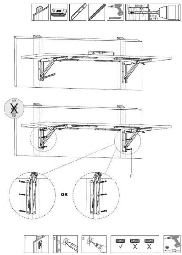
Step 1
Unfold the Arms
- Unfold the Folding Arm Mounts (#C) until the two ends are fully extended and latch into place at a 90 degree angle.

natural_image
Diagram showing a hand holding a metal bracket with a right-hand rule for assembly (no text or symbols present)Step 2
Connect the Shelf Segments
- Lay the Left, Middle, and Right Shelves (#A, #B) upside down on a flat surface in the orientation shown here so that Middle Shelf (#B) is in the center. - Attach the Shelf Connectors (#D) across the shelf segments as shown using all 32 Bolts (#D) and tighten until secure. Note: If a shorter length shelf is desired, the left and right segments can be connected without the middle segment for a 30" wide surface.

Step 3
Step 3a
Concrete/Brick Installation: Attach the Arms to the Shelf
Note: Follow this step for Concrete/Brick wall installation. For Wood Stud wall installation proceed to step 4a. - Place the Folding Arm Mounts (#C) on the bottom of the shelf, centered in the middle of the left and right shelf segments as shown here. Position the back of the mounts to the rear of the shelves, ensuring that the front of the brackets do not extend out over the front edge of the shelf. - Once the position is decided secure the Folding Arm Mounts in place using the Screws (#H) through the arms into the shelves, 4 per each arm mount.


Step 3b
Concrete/Brick Installation Option
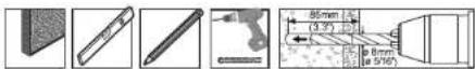
- Hold the shelf to the wall in the desired mounting location and mark the center of the mounting holes with a pencil (6 per arm.)
- Remove the shelf from the wall. Drill holes in the marked locations using a 5/16" drill bit (8mm) to a depth of 3.3"(85mm). Clear dust or debris from the holes and insert the Concrete Anchors(#G) fully until flush with the wall.
- Hold the shelf in place over the holes and anchors. Install Lag Screws(#F) through the mount arms and into the concrete anchors then tighten the screws until secure. Do not over tighten.
Note: Do not drill mounting holes into mortar (such as between bricks or stones) only drill and install into solid stone or concrete surfaces.

natural_image
Technical line drawing of a mechanical assembly with supports and a central component (no text or symbols)

Step 4
Step 4a
Wood Stud Installation: Attach the Arms to the Shelf
• Using a stud finder locate the studs and mark the edges of each stud with a pencil, then measure the distance between the center of each stud.
- Place the Folding Arm Mounts (#C) on the bottom of the shelf, so that the distance between the holes on one side only of each arm is equal to the distance between the two studs. Only 3 holes on 1 side of each arm mount will be used, ensure that these are positioned to be the same distance as the center of the studs.
- Once the position is set, secure the Folding Arm Mounts in place using the Screws (#H) through the arms into the shelves, 4 per each arm mount.


Step 4b
Wood Stud Installation Option
- Hold the shelf to the wall in the desired mounting location and mark the center of the mounting holes with a pencil (3 per arm, on one side of each arm only.)
- Remove the shelf from the wall. Use a 1/8" drill bit and drill on the marked locations to a depth of 3.1"(80mm).
- Hold the shelf in place over the holes and secure the shelf to the wall using 6x Lag Screws (#F), 3 per arm. Tighten the screws until secure.
Step 5
Folding the Shelf
• To fold the shelf down against the wall, squeeze the handles on the underside of each arm up until the latches release, then press the shelf slowly down until it stops.

natural_image
Diagram of a table with supports and a foot, showing angular measurements (no text or symbols present)Visit us at www.mount-it.com for product registration and warranty information.
Our US based customer service team is standing by to answer any questions you have about your Mount-It! product.
Available by phone Monday - Friday from 8:00am to 4:00pm PST.
Chat live with an agent on our website!

support@mount-it.com

(855) 925-5668

www.mount-it.com


- FOLDING WALL-MOUNTED SHELF
- Thank you for choosing Mount-It!
- Mount and Accessories
- DIMENSIONS & WEIGHT CAPACITY
- Step 1
- Unfold the Arms
- Step 2
- Connect the Shelf Segments
- Step 3
- Concrete/Brick Installation: Attach the Arms to the Shelf
- Step 3b
- Concrete/Brick Installation Option
- Step 4
- Step 4a
- Wood Stud Installation: Attach the Arms to the Shelf
- Step 4b
- Wood Stud Installation Option
- Step 5
- Folding the Shelf
Brand : Mount-It!
Model : MI-7993
Category : Table