YXRD-500F - Musical instrument YAMAHA - Free user manual and instructions
Find the device manual for free YXRD-500F YAMAHA in PDF.

User questions about YXRD-500F YAMAHA
0 question about this device. Answer the ones you know or ask your own.
Ask a new question about this device
Download the instructions for your Musical instrument in PDF format for free! Find your manual YXRD-500F - YAMAHA and take your electronic device back in hand. On this page are published all the documents necessary for the use of your device. YXRD-500F by YAMAHA.
USER MANUAL YXRD-500F YAMAHA
natural_image
Line drawing of a mechanical frame with wheels and support brackets (no text or symbols)シロフォン
XYLOPHONE
XYLOPHON
XYLOPHONE
XILÓFONO
木琴
실로폰
YX500FT

natural_image
Line drawing of a mechanical conveyor system with multiple slots and a handle (no text or symbols)Carefully read the contents of this manual, especially all precautions.
Before using please thoroughly read the following precautions, instructions and explanations on handling and using the instrument safely.
When assembling or disassembling the rack or xylophone, please observe the following precautions.
Especially in the case of children, a responsible adult should provide instruction on the proper use and treatment of the instrument.
Preventing Injuries—Obey all precautions described below
About the Icons
Icons are used in this section to promote the safe and proper use of this product and to prevent harm and property damage to you and others. Please fully understand the meaning of the icons before reading the manual.

This icon indicates actions that are prohibited.

This icon urges you to pay caution (includes dangers and warnings).

This icon indicates instructions that should be strictly followed

Warning
Disregard of the warnings with this mark or misuse may result in death or serious injury.
Instrument Placement

Do not place the instrument on an unstable surface such as a slope or uneven surface. The instrument may fall or overturn resulting in injury.
Instrument Handling

Do not lean on or climb on the instrument. The instrument may fall causing serious injury.

Do not play around the instrument. It may cause the instrument to fall over. Bumping into the instrument may result in injury.

Keep away from the instrument during earthquakes. Strong tremors can cause the instrument to move about or overturn.

Do not mount any instruments other than those recommended for mounting on the RD500. The RD500 rack is specially designed for use with the YX335 and YX500FT. Do not modify any instrument for installing on the rack. Doing so can result in the instrument dropping off resulting in serious injury. The YX500R and YX500F cannot be mounted on the rack.

Do not attach optional instruments to the rack with poor balance.
Because the rack can overturn or the optional instruments can drop off, this is extremely dangerous. Always make sure that the instruments are attached to the rack using the specially designed clamps, and that they are positioned to provide good balance on the rack. Attaching instruments in a poorly balanced manner outside of the rack frame or rack pipe can cause the instrument to overturn.
[Good balance] [Poor balance]

natural_image
Two identical line drawings of a mechanical apparatus with wheels and circular components, no text or symbols present.
Always assemble/disassemble the instrument on a fl at surface.
When assembling or disassembling the rack and attaching or removing the optional instruments, always work on a flat, solid surface. Working on an unstable surface such as a shaky table or sloped surface can cause the instrument to overturn.

Make sure that all nuts and bolts are firmly tightened before using the instrument.
Firmly tighten all nuts and bolts on each part after their positions have been determined. Using the instrument with loose nuts or bolts can cause the rack to overturn or instruments to drop off. Make sue that all nuts and bolts are firmly retightened before using the instrument.

Always remove the optional instrument before adjusting its height or angle.
When adjusting the height or angle of heavy optional instruments such as marching bells, chimes, etc., remove the instruments first and then adjust. Adjusting the instruments while attached to the rack can result in pinched hands or fingers causing injury.
Instrument Movement

Do not run while pushing the instrument.
The instrument may become impossible to stop, crash into a wall, and cause serious injury.

Never carry the assembled instrument up or down the stairs.
Parts may fall off, or you may loose balance resulting in serious injury. Only move the instrument after it has been disassembled.

Never try lifting the instrument by yourself when moving the instrument.
Lifting the instrument by yourself can result in pinched limbs, back injury, or other serious injury. The instrument should always be moved using at least two persons holding the rack by the leg center rail (see page 11) with both hands.
* The YX500FT weighs approximately 27kg. When attached to the RD500, their combined weight is 60kg.

When moving the instrument on its casters, hold the upper leg section and push forward slowly across smooth, fl at surfaces.
Moving the instrument on sloped, uneven, or graveled surfaces can result in the instrument overturning or running away out of control.
| CautionDisregard of cautions with this mark or misuse may result in personal injury or the loss of personal property. | |
| Handling | Be careful not to pinch your fi ngers or hands when assembling.Doing so may cause injury due to pinched fingers, etc.When assembling legs, reinforcement stays, and resonator pipes, use two persons taking special care to double-check each other as the assembly proceeds. |
| Only use genuine Yamaha clamps.Never use clamps that do not properly fit on the rack pipe,etc. when making attachments. Doing so can cause the rack to overturn or instruments to fall off resulting in serious injury. | |
| Never loosen the slide guide fi xing bolt when the xylophone is not mounted on the rack.Never loosen the slide guide fixing bolts when the xylophone is not mounted on the rack or when the legs are not attached to the rack (except for when removing the gas spring). Doing so is extremely dangerous because the rack frame (see page 11) can rise suddenly causing an accident or injury. | Always make sure that the wing bolts and wing nuts are fi rmly tightened to prevent parts from becoming loose during performance.Using the instrument with loose bolts and nuts can cause trouble during performance such as unexpected movement, etc., or parts falling off during transport resulting in injury. |
| Limits to attaching optional instrumentsThe total weight of optional instruments must not exceed 18kg. Attaching more weight can result in the entire rack overturning, becoming damaged, or the optional instruments falling off or becoming damaged.This is extremely dangerous. | Refer to the instructions when assembling the rack.Height adjustment should always be performed with at least two persons.Make sure that all procedures described in the manual are followed when assembling the rack and attaching or removing the xylophone. Disobeying the procedures can result in parts falling off from the rack during assembly, which can be dangerous. Also, height adjustment should always be performed by at least two persons. If it is absolutely necessary to adjust height by one person, do not make adjustments of more than two notches on the slide guides at a time (see page 13). |
| Do not touch cracked tone bars.Cracked tone bars have sharp edges that can cut hands.Please change cracked tone bars as soon as possible. | |
| Do not use the mallets for any other purpose than playing the instrument.Misuse of the mallets may result in unexpected injury or accidents. | |
Precautions Regarding the Gas Spring
Please observe the following instructions for proper handling of the gas spring.
* Refer to page 13 for gas spring removal.
| Caution | Disregard of cautions with this mark or misuse may result in personal injury or the loss of personal property. |
| Handling | |
| Never lubricate the moving parts on the gas spring.Lubricating the gas spring will reduce the durability of the seal and cause oil leakage. | |
| Do not expose to impacts.Doing so will cause oil leakage, malfunction, or damage. | |
| Never dismantle.High-pressure gas is sealed inside of the gas spring, so any attempt to disassemble it is extremely dangerous. | |
| Do not bend.The rod is susceptible to bending from directional loads. A poorly balanced load placed on the rod can result in bending and malfunction. | |
| Do not hit.Hitting the piston rod or cylinder can shorten the life of the seal or result in malfunction. | |
| Do not expose the instrument to excessively high or low temperatures.Doing so can cause malfunction. Use the instrument only in temperatures ranging from -20°C to 50°C. | |
| Do not expose the instrument to rain, moisture or dust.Doing so can cause malfunction. | |
| Do not use excessive force to lift the side frame, which can pull the gas spring out of the leg.Doing so can cause malfunction or damage the instrument. | |
| Do not apply a high tensile load on the gas spring.Doing so can cause malfunction or damage the instrument. | |
- In the event of a failure, stop using the instrument and contact the shop where you purchased it. If your dealer is unable to assist you, please contact Yamaha directly as per enclosure.
Danger! Disregarding any caution with this mark can place you in imminent danger resulting in death or serious injury.
Cautions when discarding the gas spring
Pressurized nitrogen gas is sealed inside of the gas spring. Be sure to release the gas before discarding the gas spring, or an explosion can occur, causing injury.
[Cautions]
- Do not push.
- Do not cut the gas spring.
- Do not throw the gas spring into a fi re.
- Do not make a hole anywhere in the gas spring other than in the specified positions (① and ② in the figure below).
[Discarding procedure]
- Put the gas spring in a plastic bag. Using a drill of 2 to 3 mm, make a hole from outside of the plastic bag at the position as specified in the figure to release the gas and oil and then make a hole at the position as specified. (Be sure to make holes in the order of and.)
- If a vinyl bag is not used, the oil and drill chips will spread. (In such a case, wear eye protection glasses.)
![YAMAHA YXRD-500F - [Discarding procedure] - 1](/content/2026/06/1225726/images/5fce4c29eba62f04707959398c4f2b00e49b8d770c28bd1fe76d139edfef59ec.jpg)
text_image
15mm Drill 2 35mm Plastic bag* Drill two holes, as shown above, to release the gas before discarding the gas spring.
Confir rmation of Packing Contents
Before assembling the frame, please take a look at the parts list and make sure that all of the required parts are accounted for.
* If any parts are missing, please contact the dealer where the frame was purchased.
● RD500 (Frame Parts only)
Ⓐ Leg Base Unit (Bass side) 1
⑧ Leg Base Unit (Treble side) 1
© Stay 1
(D) Rack pipe 1
⑤ Multi-Frame Clamp (RDC-10) 4

text_image
Unit (Bass side) ....... 1 Unit (Treble side) ....... 1 type ....... 1 me Clamp (RDC-10) ....... 4 A C B E D● YX500FT (Xylophone set)
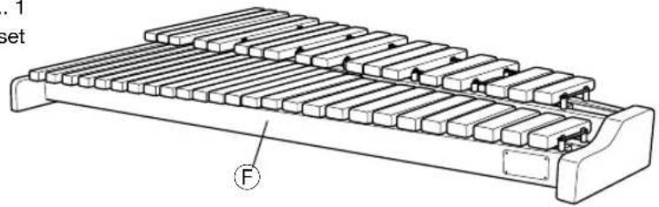
⑤ Xylophone Main Unit 1
⑥ Resonators (Natural tone side) 1
(H) Resonators (Accidental tone side) 1
① Knob Head Bolt/Spring Washer/Washer ...... 4 set
text_image
. 1 set F
text_image
G H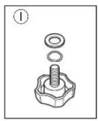
natural_image
Mechanical assembly diagram showing a bolt and washer with no text or symbolsAssembly
First, assemble the Multi-Frame (RD500) then attach the xylophone set (YX500FT) onto the frame.

For safety reasons, make sure that assembly of the Multi-Frame and attaching of the instrument is carried out with two or more persons, and that you assemble the product in an area with adequate space.
Fully insert the end of stay Ⓐ with its notch facing up into the joint on leg base Ⓐ, then firmly tighten the wing bolt.
* Pay attention to the stay's orientation when attaching. Parts are marked with letters to assist with assembly. (Refer to the diagram below.)
2 Remove the wing nut, washers, and spring washers on the center rail of the bass side leg base Ⓐ, slide the C-shaped end of the diagonal stay support Ⓐ onto the bolt on the center rail then tighten the wing nut firmly with washer and spring washer.
3 Use the same procedure to connect the clamp and diagonal stay support on stay © to the center rail on the treble side leg base Ⓑ.
4 Loosen the clamp screws on both ends of the rack pipe ① and fasten the clamps onto the poles on the upper leg section.
The rack pipe can be attached so its clamp side is either on the audience side or the player's side of the pole. Decide how much space you need between the rack pipe and tone bars and attach the rack pipe accordingly.
* Please make sure that the YAMAHA logo is not placed upside-down.
5 Firmly tighten all bolts.
Assembly of the Multi-Frame is complete.

When disassembling the multi-percussion rack, follow the assembly steps in reverse order.
1.3

text_image
A (B) Leg base Notch C Stay Wing bolt2,3

text_image
Tighten Wingnut Spring washer Washer A (B) Center rail © Diagonal stay support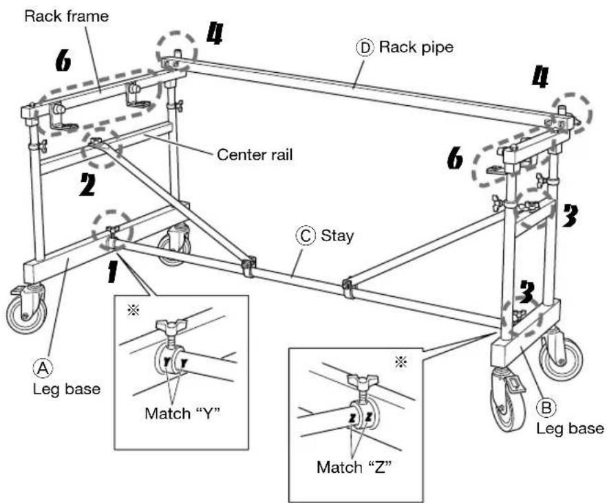
text_image
Rack frame 6 4 D Rack pipe Center rail 2 6 3 C Stay 1 A Leg base Match "Y" Match "Z" B Leg base
text_image
Pole Tighten A (B) Rack frame D Rack pipe(D) Rack pipe

natural_image
Two mechanical diagrams showing lever mechanism with weights and supports (no text or symbols)Next, attach the instrument to the rack.
* Do not let the resonators hit against the legs or other part of the frame during their installation.
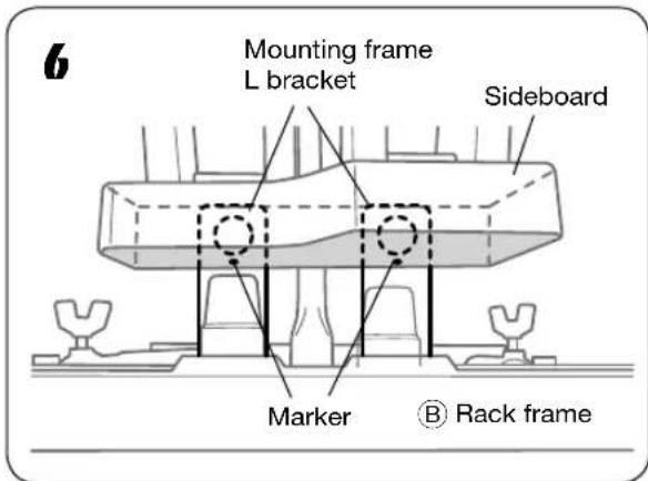
6 Align the bolt holes on the underside of the sideboard with the holes on the L-shaped bracket attached to the rack frame and set the instrument onto the rack.
Use the white marker* on the sideboard (on its outer side) as an aid when aligning. The marker should be centered on the L-shaped bracket for proper alignment.
* The YX335 does not have a white marker.
7 Use the supplied bolts, washers, and spring washers ① attached to the instrument to attach the instrument from the underside of the rack (4 locations).
8 First pass the resonators through the instruments from underneath the rail and then mount the treble end into the resonator rest.
9 Next, mount the bass side. Pass the end of the resonators through the space in the center of the resonator rest as shown in the diagram, and fit it into the notch in the resonator rest.
When room temperature is 73.4^ F ( 23^ C) and above, set the resonators into the shallow notches of the resonator rest (Diagram A).
When room temperature is 73.4^ F ( 23^ C) and below, set the resonators into the deeper notches of the resonator rest (Diagram B).
10 Use the same procedure to install the other set of resonators.
After assembly is complete, firmly tighten all bolts.

To disassemble, follow the assembly steps in reverse order.
text_image
Mounting frame L bracket Sideboard Marker Rack frame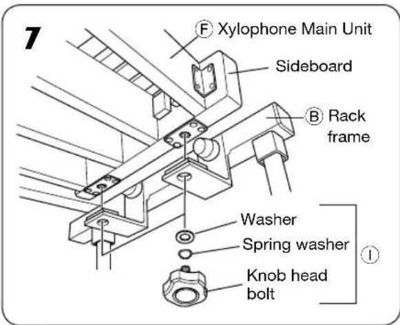
text_image
7 F Xylophone Main Unit Sideboard B Rack frame Washer Spring washer Knob head bolt8,9

text_image
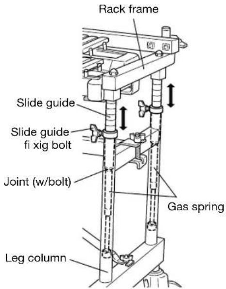
Notch Resonator rest Resonator rest Diagram A (Above 23°C: Shallow notch) Diagram B (Below 23°C: Deep notch) Resonators (Accidental tone side) Resonators (Natural tone side) 1 2 Bass side Treble sideAdjusting the Height of the Playing Surface

Never loosen the slide guide fixing bolts when the xylophone is not mounted on the rack or when the legs (A and B) are not attached to the rack.

When adjusting the height of the playing surface, make sure that adjustment is carried out by at least two people. If a single person must unavoidably carry out adjustment, do not move the guides any more than 2 slide guide memory positions at a time.
- While supporting both bass and treble sides of the frame with your hands, loosen the slide guide fi xing bolts.
- Gas springs in the rack slide guides will cause the instrument to rise automatically. After adjusting the instrument to the required height, tighten the fixing bolts firmly. Use the guides on the slide guides to adjust the playing surface so it is parallel to the floor.
text_image
Rack frame Slide guide Slide guide fi xig bolt Joint (w/bolt) Gas spring Leg columnRemoving the Gas Springs

Never remove the gas springs except when discarding.
- Loosen all four slide guide fixing bolts when the instrument is mounted on the rack, raise the rack frame all of the way up, then tighten the four slide guide fixing bolts. (Refer to the diagram shown above for part names.)
- Remove the instrument from the rack and disassemble the rack so that the leg sections are removed from the frame. (Reverse the order of the instructions in the assembly section on pages 11-12.)
- Loosen the two slide guide fixing bolts and slide the slide guide sections out of the leg column.
- Loosen the gas spring attached to the bottom of the slide guide and remove.
* The two parts are threaded and screw together.
Specifications
RD500
● Height Adjustment:
Gas spring type 85 – 100 cm (33-7/16" x 39-3/8")
(With the YX500FT attached: Measured from the accidental tone bars) 83 - 98 cm (32-11/16" x 38-9/16")
● Caster Diameter: 150 mm (5-7/8")
● Dimensions (W x D): 164 x 107 cm (64-9/16" x 42-1/8") (Full depth including casters)
● Weight: 33 kg (72 lbs 12 oz)
■ YX500FT
● Range: F45 – C88 (3-1/2 octave)
● Standard Pitch: 442Hz
● Bars: Acoustalon (FRP), Brown Urethane Finish
● Bar sizes: 38.1 mm (1-1/2") wide 23 mm (7/8") thick
● Resonators: Steel Pipe, Light Gold Acrylic Coating
● Frame: Beech, Black Enamel Matte Finish
- Dimensions (W x D x H):
137.5 x 75 x 31 cm (54-3/8" x 29-1/2" x 12-3/16")
● Weight: 27 kg (59 lbs 8 oz)
■ Scale Range

text_image
1 3 4 6 8 9 11 13 15 16 18 20 21 23 25 27 28 30 32 33 35 37 39 40 42 44 45 47 49 51 52 54 56 57 59 61 63 64 66 68 69 71 73 75 76 78 80 81 83 85 87 88 Middle C YX500FT* Specifications subject to change without notice.
