A815 - Camera ACTi - Free user manual and instructions
Find the device manual for free A815 ACTi in PDF.

User questions about A815 ACTi
0 question about this device. Answer the ones you know or ask your own.
Ask a new question about this device
Download the instructions for your Camera in PDF format for free! Find your manual A815 - ACTi and take your electronic device back in hand. On this page are published all the documents necessary for the use of your device. A815 by ACTi.
USER MANUAL A815 ACTi
natural_image
Abstract geometric design with a red square and a gray star-like shape (no text or symbols)A8x Outdoor Dome Series Hardware Manual
A84, A85, A86, A87, A815, A817
2023/10/19
Table of Contents
Precautions 4
Safety Instructions 6
Introduction......7
The List of Models 7
Package Contents......8
Physical Description 9
Mounting Options....11
Installing the Camera on a Surface 12
Step 1: Drill the Holes.... 12
Step 2: Prepare the Camera....13
Step 3: Waterproof the Cable Connection....16
Option 1: Cable Passing Through the Surface and Bottom Cable Holes....16
Option 2: Cable Passing Along the Surface and the Camera Side Cable Hole....19
Step 4: Connect to Network....25
Step 5: Access the Camera Live View.... 25
Step 6: Adjust the Viewing Angle ...... 26
Step 7: Close the Dome Cover....26
Other Connections......27
Connecting a Power Adapter (Optional) 28
Connecting Input / Output Devices (Optional) 28
How to Connect DI/DO Devices.... 28
How to Connect Audio Input / Output Devices 30
How to Connect a Video Output Device.... 30
Other Accessories 31
How to Install / Remove the Memory Card 31
How to Insert the Memory Card.... 31
How to Remove the Memory Card.... 31
How to Attach the RJ-45 Connector.... 32
Accessing the Camera 34
Configure the IP Addresses.... 34
Access the Camera.... 38
Precautions
Read these instructions
You should read all the safety and operating instructions before using this product.
Heed all warnings
You must adhere to all the warnings on the product and in the instruction manual. Failure to follow the safety instruction given may directly endanger people, cause damage to the system or to other equipment.
Servicing
Do not attempt to service this video device yourself as opening or removing covers may expose you to dangerous voltage or other hazards. Refer all servicing to qualified service personnel.
Trademarks
All names used in this manual are probably registered trademarks of respective companies.
Liability
Every reasonable care has been taken during the writing of this manual. Please inform your local office if you find any inaccuracies or omissions. We cannot be held responsible for any typographical or technical errors and reserve the right to make changes to the product and manuals without prior notice.
Federal Communications Commission Statement
This device complies with Part 15 of the FCC Rules. Operation is subject to the following two conditions:
- This device may not cause harmful interference.
- This device must accept any interference received, including interference that may cause undesired operation.
Note: This equipment has been tested and found to comply with the limits for a Class A digital device, pursuant to Part 15 of the FCC Rules. These limits are designed to provide reasonable protection against harmful interference when the equipment is operated in a commercial environment. This equipment generates, uses, and can radiate radio frequency energy, and if it is not installed and used in accordance with the instruction manual, it may cause harmful interference to radio communications. Operation of this equipment in a residential area is likely to cause harmful interference, in which case the user will be required to correct the interference at their own expense.
European Community Compliance Statement
CE This product has been tested and found to comply with the limits for Class A Information Technology Equipment according to European Standard EN 55022
and EN 55024. In a domestic environment, this product may cause radio interference in which cause the user may be required to take adequate measures.
Safety Instructions
Cleaning
Disconnect this video product from the power supply before cleaning.
Attachments
Do not use attachments not recommended by the video product manufacturer as they may cause hazards.
Do not use accessories not recommended by the manufacturer
Install the PoE switch or injector and other devices that will be used with the camera in a dry place protected from weather.
Servicing
Do not attempt to service this video product yourself. Refer all servicing to qualified service personnel.
Damage Requiring service
Disconnect this video product from the power supply immediately and refer servicing to qualified service personnel under the following conditions.
1) When the power-supply cord or plug is damaged
2) If liquid has been spilled, or objects have fallen into the video product.
3) If the inner parts of video product have been directly exposed to rain or water.
4) If the video product does not operate normally by following the operating Instructions in this manual. Adjust only those controls that are covered by the instruction manual, as an improper adjustment of other controls may result in damage, and will often require extensive work by a qualified technician to restore the video product to its normal operation.
Safety Check
Upon completion of any service or repairs to this video product, ask the service technician to perform safety checks to determine if the video product is in proper operating condition.
Introduction
The List of Models
This hardware manual contains the following models:
| A84 |  | 12MP, Outdoor Zoom Dome, Day / Night, Adaptive IR, Advanced WDR, Superior Low Light Sensitivity, 3x Zoom Lens |
| A85 |  | 2MP, Outdoor Zoom Dome, Day / Night, Adaptive IR, Extreme WDR, Extreme Low Light Sensitivity, 4.3x Zoom Lens |
| A86 |  | 5MP, Outdoor Zoom Dome, Day / Night, Adaptive IR, Extreme WDR, Superior Low Light Sensitivity, 5x Zoom Lens |
| A87 |  | 5MP, Outdoor Zoom Dome, Day / Night, Adaptive IR, Advanced WDR, Superior Low Light Sensitivity, 4.3x Zoom Lens |
| A815 |  | 3MP, Outdoor Zoom Dome, Day / Night, Adaptive IR, Extreme WDR, Superior Low Light Sensitivity, 4.3x Zoom Lens |
| A817 |  | 8MP Face, People and Car Detection Outdoor Zoom Dome, Day / Night, Adaptive IR, Extreme WDR, Superior Low Light Sensitivity, 4.3x Zoom Lens |
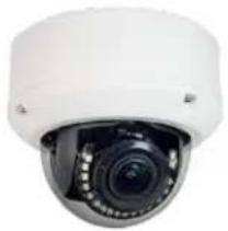
Package Contents
| Camera | Mounting Screws | Allen Wrench |
 |  |  |
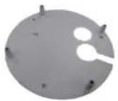
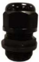
| Base Plate | Conduit Gland | Cable Gland |
 |  |  |
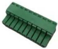
| Terminal Block | Cable Hole Cap | Drill Template |
 |  |  |
| Quick Installation Guide & Warranty Card | ||
 | ||
Physical Description

text_image
Labeled diagram of a camera module showing internal components and parts with numbered annotations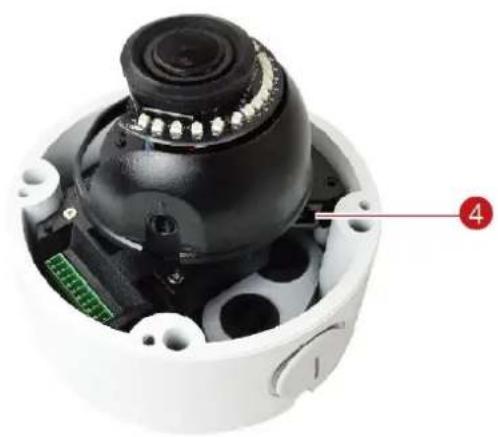
natural_image
Interior view of a black-and-white surveillance camera module with visible wiring and a green circuit board (no text or symbols)NOTE: The camera picture above is for reference only. Actual camera may slightly differ.
| Item | Description | |
| 1 | Input / Output Connector | |
| DC 12V Power Input | In case the camera is connected to a non-PoE (Power over Ethernet) switch, use this connector to connect the camera to an external power adapter (not included). See Connecting a Power Adapter (Optional) on page 28 for more information. | |
| Audio Input / Output | Connects to an audio input and output device, such as a microphone and speaker. See How to Connect Audio Input / Output Devices on page 30 for more information. | |
| Digital Input / Output | Connects to digital input or output devices, such as an alarm trigger, panic button, etc., as well as audio input and output devices, such as microphones and speakers. Digital Input (DI) and Digital Output (DO) devices are used in applications like motion detection, event triggering, alarm notifications, etc. See How to Connect DI/DO Devices on page 28 for more information. | |
| 1 | DC 5V Power Output | Provides DC 5V power for digital output devices. |
| Video Output | Connects to a video output device, such as a camera installation kit, for camera adjustments on the installation site. See How to Connect a Video Output Device on page 30 for more information. | |
| 2 | Reset Button | Restores the factory default settings of the camera. To reset the camera, press and hold the Reset Button for at least 10 seconds. |
| 3 | Memory Card Slot | Insert a memory card into this slot for local recording purposes. See How to Install / Remove the Memory Card on page 31 for more information.NOTE: Supports microSDHC and microSDXC cards. |
| 4 | Ethernet Port | Connects to a network using an Ethernet cable. |
Mounting Options
There are several mounting options that you can use to install the camera. Select the most suitable solution for your installation environment.
| Mount Types | Accessories |
| Surface Mount | Suitable when mounting the camera directly walls or ceilings without extra accessories. See Installing the Camera on a Surface on page 12 for mounting instructions. |
| Straight Wall Mount | Suitable when mounting the camera on straight walls. |
| Pendant Mount | Suitable when mounting the camera on hard and high ceilings. |
| Pole Mount | Suitable when mounting the camera on vertical poles. |
| Corner Mount | Suitable when mounting the camera on a corner wall. |
NOTE:
- For more information about the mounting solutions and accessories, please check the Mounting Accessory Selector in our website (http://www.acti.com/mountingselector).
- The above mounting accessories are not included in the package. Contact your sales agents to purchase.
Installing the Camera on a Surface
This section describes the procedures in installing the camera on a flat surface such as a hard or dropped ceiling and straight or tilted walls. Before installation, make sure the wall or ceiling can bear more than the weight of the camera.
Step 1: Drill the Holes
Before drilling the holes, note the direction of the connectors side of the camera, which is also the opposite side of the camera logo. This influences the camera placement and where you should drill the hole where the cables will pass through or how the cables will go along the ceiling or wall.
- According to the preferred camera orientation, attach the bundled drill template and mark the screw holes location.
-
Determine how the cables will be routed: pass through the surface or along the surface.
-
If the cables will pass through the surface, drill the cable hole and the three (3) screw holes on the surface.
-
If the cables will be routed along the surface, just drill the three (3) screw holes on the surface.
-
Insert the plastic plugs into the screw holes, if necessary.
Step 2: Prepare the Camera
NOTE: To avoid scratches or leaving fingerprints on the dome cover, it is recommended to retain the plastic covering the dome cover until the camera is completely installed. However, the plastic has been removed on the pictures in this documentation to show clarity of the procedures being described.
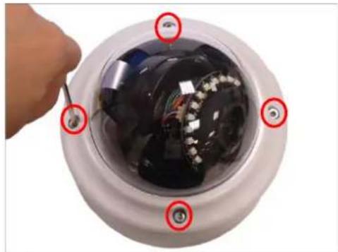
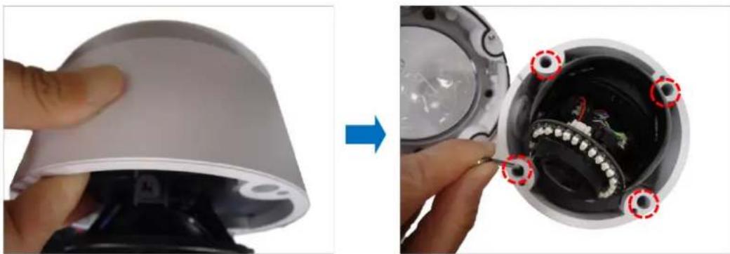
- Loosen the four (4) screws securing the dome cover and lift to open the dome cover.
natural_image
Close-up of a hand holding a screwdriver next to a dark, illuminated camera lens with visible internal components (no text or symbols)- Loosen the four (4) screws and detach the base plate from the camera.

natural_image
Close-up of a device's internal components being removed, showing a hand holding a screwdriver and a white plastic housing (no text or symbols visible)- Using the drill template, mark the screw holes and cable holes (as needed). Then install the base plate to the wall or ceiling surface using the bundled screws. Take note of the orientation of the camera before you mount the base plate.
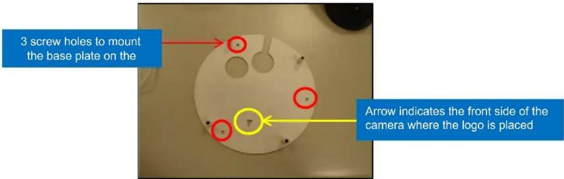
text_image
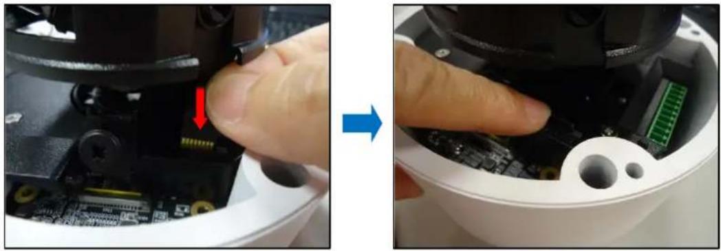
3 screw holes to mount the base plate on the Arrow indicates the front side of the camera where the logo is placed- If necessary, insert a memory card with the metallic contacts facing the "MicroSD" label of the camera. Then push the card until it locks into place.
natural_image
Close-up of a robotic device showing a hand inserting a component into a circuit board, with no visible text or symbols.- Prepare for cabling connections.
a. If the cable will pass through the surface, follow the procedures in Option 1: Cable Passing Through the Surface and Bottom Cable Hole on page 16.
b. If the cable will be routed along the surface, mount the camera to the surface then follow the procedures in
a. Option 2: Cable Passing Along the Surface and the Camera Side Cable Hole on page 19.
To mount the camera, make sure to align the camera to the base plate then tighten the four (4) screws to complete installing the camera to the surface.

natural_image
Close-up of a hand holding a white cylindrical device, showing the internal components and a close-up view of the device's interior (no text or symbols visible)Step 3: Waterproof of the Cable Connection
Depending on the installation environment, the cable can pass through the surface and go through the bottom hole of the camera or pass along the surface and through the side hole of the camera. Refer to the instructions below to protect the cable connections.
Option 1: Cable Passing Through the Surface and Bottom Cable Holes
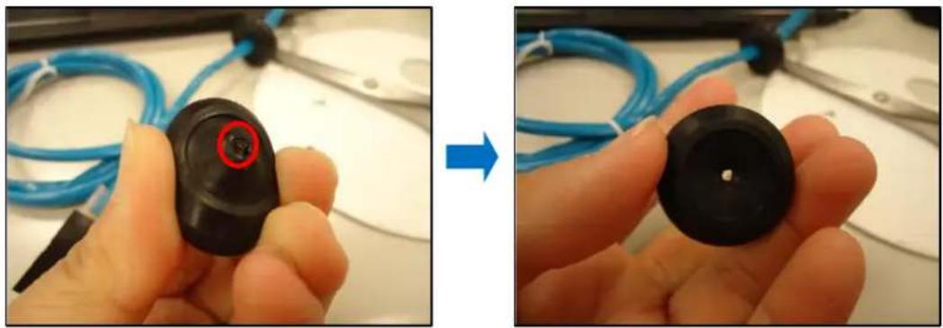
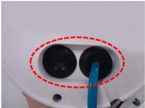
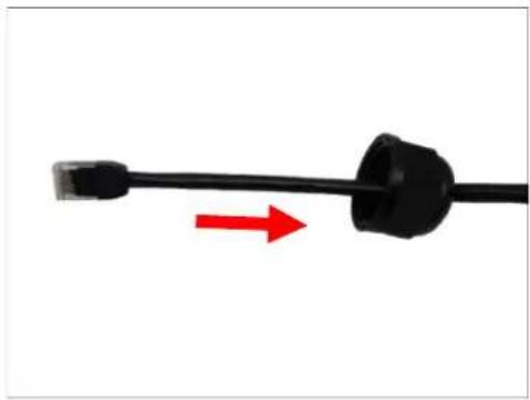
- There are two (2) cable holes on the bottom side of the camera. Ideally, one hole is for the Ethernet cable and the other for other input/output devices that will be connected to the camera. Remove the rubber of the hole(s), as needed. Push the rubber from the inside of the camera to pull it off from the outside.

natural_image
Circular device with two black circular components and a red dashed oval highlighting them (no text or symbols)- Cut off the tip of the rubber. This is where the cable will pass through.
natural_image
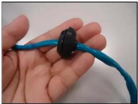
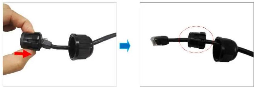
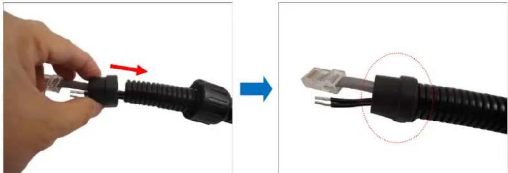
Close-up of a hand holding a black plastic component with a red circular mark, alongside a blue wire and cable (no text or symbols visible)- Route the Ethernet cable without RJ-45 connector head through the surface. Then insert the Ethernet cable through the rubber.
natural_image
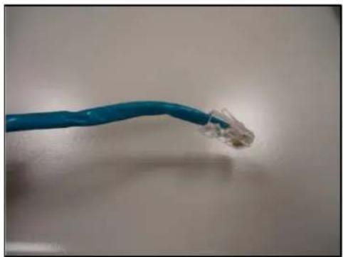
Close-up of a hand holding a blue cable with a black connector (no text or symbols visible)- Once the Ethernet cable passes through the camera hole, attach the RJ-45 connector (see How to Attach the RJ-45 Connector on page 32 for detailed information).
natural_image
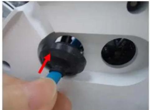
Close-up of a blue wired network cable with a metallic connector (no text or symbols visible)- Insert the rubber back into the camera bottom hole.
natural_image
Close-up of a hand inserting a black plastic component into a white mechanical housing, with a red arrow pointing to the component (no text or symbols visible)- Pull enough Ethernet cable length to be able to connect to the Ethernet port of the camera.

natural_image
Close-up of a gloved hand holding a blue tool near a mechanical component with a red arrow indicating direction (no visible text or symbols)- Do the same procedures to connect other input/output devices to the camera. When done, seal the bottom cable hole(s) with silicon to protect it from water leak.
natural_image
Close-up of a white appliance with two black circular components and a blue tool inserted, enclosed in a red dashed oval (no text or symbols visible)NOTE: If no other devices will be connected, make sure that the other rubber is properly placed on the camera cable hole.
- Align the camera to the base plate then tighten the screws to complete mounting the camera on the surface.
natural_image
Close-up of a hand holding a white plastic cup, before and after assembly (no text or symbols visible)DISCLAIMER: ACTi will not be responsible for camera damage caused by improper installations or the misuse of equipment for installation.
- Connect the Ethernet cable to the Ethernet port of the camera.

natural_image
Close-up of a hand inserting a blue USB into a mechanical component, with a red arrow indicating the cable direction (no text or symbols visible)NOTE: If the side cable hole will not be used, make sure to cover it with the bundled cable hole cap.
Option 2: Cable Passing Along the Surface and the Camera Side Cable Hole
The camera comes with two (2) glands used to waterproof the side cable hole. Determine the type of waterproof solution that is applicable to your installation requirements and prepare the necessary accessories or purchase extra materials.
| Bundled Accessory | Description |
| Cable Gland | Use this solution when connecting an Exterior-grade Ethernet cable between the camera and a Power-over-Ethernet (PoE) switch or injector. Exterior-grade Ethernet cables are already waterproof. See Waterproof Solution with Naked Cable on page 20. 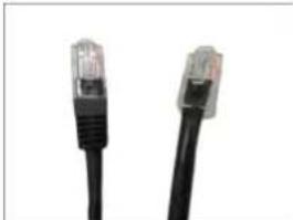 NOTE:• Exterior-grade cables are already waterproof. Not included in the package.• Use only RJ-45 connectors without sleeve. NOTE:• Exterior-grade cables are already waterproof. Not included in the package.• Use only RJ-45 connectors without sleeve. |
 | |
| Conduit Gland | Use this solution when connecting a standard indoor Ethernet cable between the camera and a Power-over-Ethernet (PoE) switch / injector. A flexible conduit (trade size 1/2") is required to house the Ethernet cable. This solution is recommended when other cable connections, such as audio, DC 12V, etc. will be connected to the camera. See Waterproof Solution with Conduit on page 22.NOTE: The flex conduit is not included in the package and must be purchased separately. |
 |
Waterproof Solution with Naked Cable
This section describes the procedures in using the bundled cable gland and an exterior-grade Ethernet cable.
- Disassemble the cable gland as shown below:
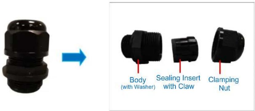
text_image
Body (with Washer) Sealing Insert with Claw Clamping Nut- Insert the clamping nut into the Ethernet cable.
natural_image
Close-up of a black cable with a red arrow pointing to its end, against a white background (no text or symbols)- Insert the sealing insert with claw.
natural_image
Close-up of a black cable connector being inserted, showing wiring and a close-up detail (no text or symbols visible)- Attach the cable gland body to the hole of the camera.

natural_image
Close-up of a hand pressing a black plastic component with red arrow (no text or symbols visible)- Insert the cable through the camera hole.

natural_image
Close-up of a cable connector with black connectors and a red arrow indicating direction (no text or symbols)- Connect the cable to the Ethernet port of the camera.
- Insert the sealing insert with claw into the cable gland body and then attach the clamping nut to complete the cable solution.
natural_image
Close-up of a black plastic plug being inserted into a cable, showing red arrows indicating direction (no text or symbols)NOTE: Make sure the clamping nut is tightly attached to the cable gland body and the sealing insert is squeezed tightly.
Waterproof Solution with Conduit
This section describes the procedures to waterproof the cabling connections using the bundled conduit gland and flexible conduit. This is the recommended solution if other input/output devices or an external power adapter will be connected to the camera or when an exterior-grade Ethernet cable is not available.
- Prepare the following materials for waterproof installation:
| Conduit Gland(included in the camera package) | Flexible Conduit1/2" Trade size(not included in the package) | Network CableCAT 5 or CAT 6(not included in the package) |
 |  |  |
- Disassemble the bundled conduit gland as shown below:

text_image
Lock Nut Body Sealing Insert Clamping NutNOTE: In this installation, the conduit gland body can be securely attached to the mount kit; therefore the use of lock nut is not necessary. Please set the lock nut aside.
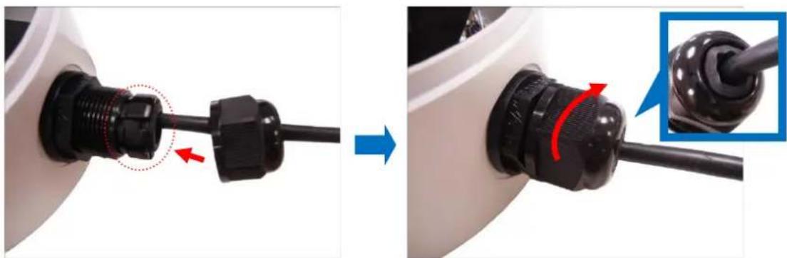
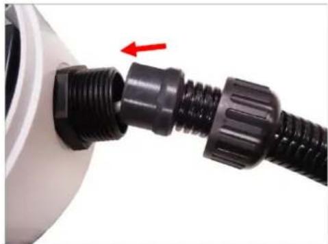
- Screw the conduit gland body to the conduit hole of the camera.
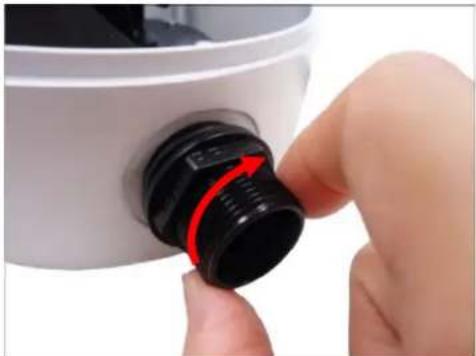
natural_image
Close-up of a hand holding a black plastic brush tip with red arrow indicating rotation (no text or symbols visible)- Pull the network cable through the flex conduit. If connecting other input/output devices or an external power adapter, pull the cables through the flex conduit without connectors. The terminal blocks will be attached once the cables pass through the camera hole later.
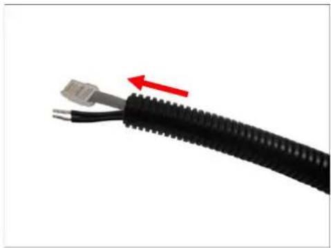
natural_image
Close-up of a black cable with two connectors and a red arrow indicating direction (no text or symbols)- Insert the clamping nut through the flex conduit.
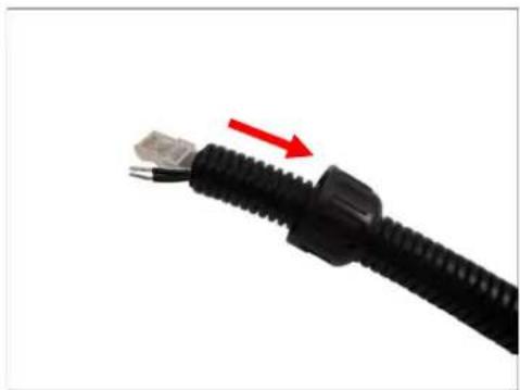
natural_image
Close-up of a black cable with a red arrow pointing to its connector (no text or symbols visible)- Insert the sealing insert and attach it at the end of the flex conduit.
natural_image
Close-up of a hand holding a black USB connector with red and blue arrows indicating connection (no text or symbols)- Insert the network cable and other cables (if any) through the camera conduit hole; pull enough cable length to connect to the camera.
natural_image
Close-up of a black plastic plug connector with a red arrow indicating direction (no text or symbols visible)- Insert the sealing insert to the gland body and then attach the clamping nut to complete the cable solution.

natural_image
Close-up of a black plastic plug being inserted into a white container, showing red and blue directional arrows (no text or symbols)- Connect the network cable to the Ethernet port of the camera.

natural_image
Close-up of a hand inserting a blue USB into a mechanical component (no visible text or symbols)- Connect other cables (if any) to their respective connectors. See Other Connections on page 27 for detailed instructions.
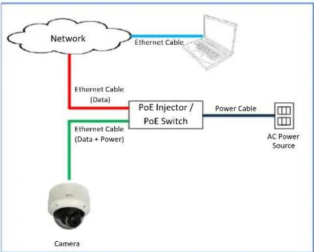
Step 4: Connect to Network
Connect the other end of the network cable to a switch or injector. Then, connect the switch or injector to a network or PC and a power source. See Power-over-Ethernet (PoE) example connection diagram below.
flowchart
graph TD
    A["Network"] -->|Ethernet Cable (Data)| B["PoE Injector / PoE Switch"]
    A -->|Ethernet Cable (Data + Power)| C["Camera"]
    B -->|Power Cable| D["AC Power Source"]
    D -->|Ethernet Cable| A
    style A fill:#f9f,stroke:#333
    style B fill:#ccf,stroke:#333
    style C fill:#cfc,stroke:#333
    style D fill:#fcc,stroke:#333
Step 5: Access the Camera Live View
See Accessing the Camera on page 34 for more information on how to access the Live View of the camera.
Step 6: Adjust the Viewing Angle
Based on the live view, adjust the viewing angle and orientation of the camera.
- Loosen the pan adjustment screw, then turn the lens module to pan the camera.
- Tighten the pan adjustment screw to fix its pan position.

text_image
Pan Adjustment Screw Tilt Adjustment ScrewNOTE: Be careful when turning the lens module to its extent as cables are connected inside the module.
- Loosen the tilt adjustment screw and then tilt the camera to desired angle.
- Tighten the tilt adjustment screw to fix the lens position.
Step 7: Close the Dome Cover
Tighten the four (4) screws to attach the dome cover to the camera body.

natural_image
Close-up of a hand holding a screwdriver next to a dark spherical device with visible wiring and components (no text or symbols)Other Connections
This section describes the procedures in preparing an external power adapter or other input and output devices, such as digital or alarm, audio and video that you can connect to the camera. The use of these devices, however, is optional.
Use the bundled terminal block to connect other devices to the camera. The terminal block pin definition of each model may vary. Refer to the table below:
| A84 | A87, A815 | A85, A86, A817 |
| 12V _IN | ||
| 12V_GND | GND | 12V _IN |
| A_GND | AI | 12V_GND |
| AI | A_GND | A_GND |
| AO | AO | AI |
| VO | 12V_OUT | AO |
| GND | VO | 5V_OUT |
| GND | RESET | GND |
| DI | DI | GND |
| DO | DO | DI |
To connect a device, slightly loosen the terminal block screws then insert the cables of the device to the corresponding pins on the terminal block. Tighten the screws to secure the cable. Refer to the succeeding sections for detailed instructions.
NOTE: Make sure to let the device cables pass through the camera holes first before connecting them to the terminal block.
Connecting a Power Adapter (Optional)
The camera can be powered by a Power over Ethernet (PoE) switch that is IEEE802.3af compliant. In case of using a non-PoE switch or your PoE switch has limited power supply, you can purchase a power adapter and directly connect the camera to a power outlet.
NOTE: The power adapter is not bundled in the package.
The camera comes with a terminal block where you can connect other devices as well as the power adapter.
Take note that a standard power adapter cable has two (2) different wires. Connect the wire with the white stripe to the DC12V pin on the terminal block and the other wire to the GND pin.

text_image
Connect to GND Pin White stripe: Connect to DC12V PinConnecting Input / Output Devices (Optional)
Depending on your surveillance needs, you may connect digital input / output, audio input / output, and video output device to your camera.
How to Connect DI/DO Devices
To connect digital input / output devices (DI/DO), map the pins to one of the pin combinations below:
| Device | Mapping Instructions | |
| Digital Output (DO) | DO | Connect the wires of the output device to DO and 5V. |
| 5V | ||
| Digital Input (DI) | DI | Connect the wires of the input device to DI and GND. |
| GND | ||
The table below shows the DI/DO connection specifications:
| Device | |||
| DI | Connection design | TTL - compatible logic levels | |
| Voltage | To trigger (low) | Logic level 0: 0V ~ 0.4V | |
| Normal (high) | Logic level 1: 3.3V | ||
| DO | Connection design | Transistor (Open Collector) | |
| Voltage & Current | 5V DC, < 50mA | ||
Typical Connection
Based on these specifications, if the DI device has a voltage of 3.3V or the DO device has a voltage of 5V (< 50mA), then the camera can supply internal power to these devices and there is no need to connect the DI/DO device to an external power source.
In this case, wire connection to Pins 1 to 4. Use the GND and DI pins to connect a DI device and use the 5V and DO pins to connect a DO device. See wiring scheme below:
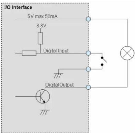
text_image
I/O Interface 5V max 50mA 3.3V Digital Input Digital OutputNOTE: For more information on DI/DO connections, please refer to the Knowledge Base article
All about Digital Input and Digital Output downloadable from the link below
(http://Download.acti.com?id=516).
How to Connect Audio Input / Output Devices
Audio input and output devices, such as a microphone and speaker, can be connected to the camera.
The camera supports both the active (line-in) and passive (mic-in) microphone.
To connect audio devices, map the pins to one of the pin combinations below:
| Device | Pin | Mapping Instructions |
| Audio Output (AO) | AO | Connect the wires of the audio output device to AO and A-GND. NOTE: Must power up the audio output device with external power source, refer to the device documentation for details. |
| A-GND | ||
| Audio Input (AI) | AI | Connect the wires of the audio input device to AI and A-GND. |
| A-GND |
NOTE: For more information about AUDIO in connections, please refer to the Knowledge Base article How to Use Audio-in of ACTi Cameras, downloadable from the link below (http://Download.acti.com?id=534).
How to Connect a Video Output Device
NOTE: The video output connector is available in select models only.
The video output device, such as the Camera Installation Kit, can be connected to the camera to see the live view during installation through the Camera Installation Kit BNC connection.
To connect the video output device, map the pins of the BNC cable to the terminal block as follows:
| Device | Pin | Mapping Instructions |
| Video Output (VO) | VO | Connect the wires of the video output device to VO and GND.NOTE: Must power up the video output device with external power source, refer to the device documentation for details. |
| GND |
Other Accessories
How to Install / Remove the Memory Card
The camera supports local video recording to a memory card.
NOTE: Supports microSDHC and microSDXC cards.
How to Insert the Memory Card
Insert a memory card into the card slot with the metallic contacts facing the "MicroSD" label on the camera. Push the card until it clicks into place.

natural_image
Close-up of a hand inserting electronic components into a white plastic housing, showing part assembly and wiring (no text or symbols visible)How to Remove the Memory Card
In case there is a need to remove the card, make sure to access the camera Web Configurator to safely "unmount" the card first (see the camera Firmware manual for more information). Once unmounted from the firmware, push the card to eject it from the slot.
How to Attach the RJ-45 Connector
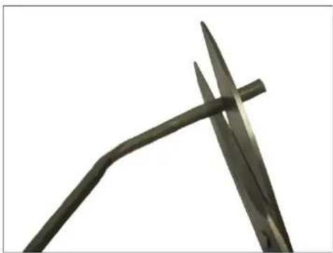
- Prepare the following tools:
a. RJ-45 connector
b. Crimping tool
c. Scissors
- Cut about one (1) inch into the plastic sheath from the end of the cable.
natural_image
Close-up of a metal tool with sharp tip and curved handle against white background (no text or symbols)- Unwind the wires and arrange them according to the color sequence below.
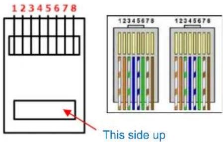 | 1 | Stripe Orange |
| 2 | Orange | |
| 3 | Stripe Green | |
| 4 | Blue | |
| 5 | Stripe Blue | |
| 6 | Green | |
| 7 | Stripe Brown | |
| 8 | Brown |
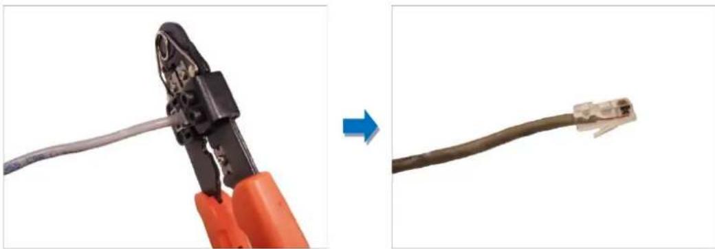
- Straighten out the wires and use the scissors to make a straight cut 12 inch from the cut end.

natural_image
Close-up of a cable with exposed internal wires being removed, showing structural change (no text or symbols)- With the RJ-45 connector tab facing down, push down the wires into the connector all the way to the end.
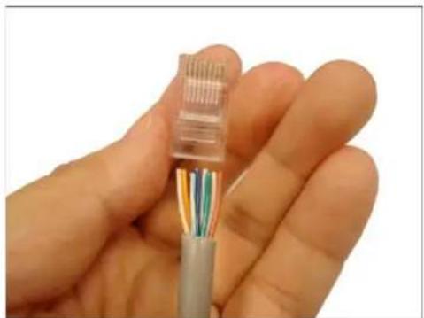
natural_image
Close-up of a hand holding a transparent cable with multicolored wires (no text or symbols visible)- Place the connector into the crimping tool, and cinch down to secure the RJ-45 connector to the Ethernet cable.
natural_image
Close-up of a wire being adjusted to a cable, showing the wire being held and then connected to a network connector (no text or symbols visible)Accessing the Camera
Configure the IP Addresses
In order to be able to communicate with the camera from your PC, both the camera and the PC have to be within the same network segment. In most cases, it means that they both should have very similar IP addresses, where only the last number of the IP address is different from each other. There are 2 different approaches to IP Address management in Local Area Networks – by DHCP Server or Manually.
Using DHCP server to assign IP addresses:
If you have connected the computer and the camera into the network that has a DHCP server running, then you do not need to configure the IP addresses at all – both the camera and the PC would request a unique IP address from DHCP server automatically. In such case, the camera will immediately be ready for the access from the PC. The user, however, might not know the IP address of the camera yet. It is necessary to know the IP address of the camera in other to be able to access it by using a Web browser.
The quickest way to discover the cameras in the network is to use the simplest network search, built in the Windows system – just by pressing the “Network” icon, all the cameras of the local area network will be discovered by Windows thanks to the UPnP function support of our cameras.
In the example below, we successfully found the camera model that had just connected to the network.
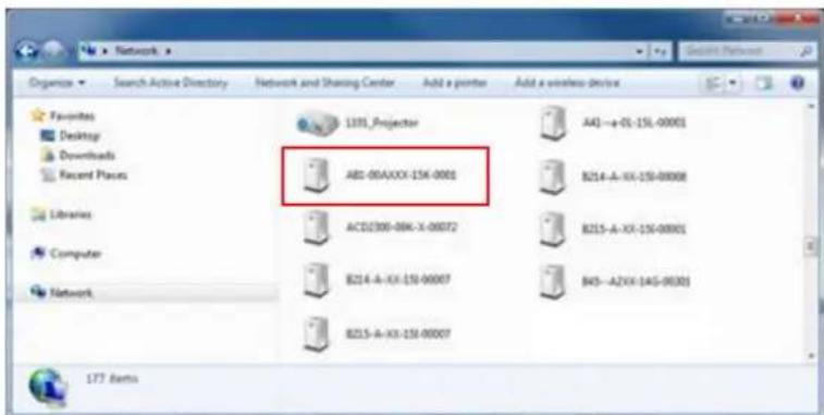
text_image
Network Organize Search Active Directory Network and Sharing Center Add a pointer Add a wireless device Favorites Desktop Downloads Recent Places Libraries Computer Network 1391 Projector A81-06AXXX-154-0001 B214-A-XX-154-00008 ACD300-08K-X-00072 B215-A-XX-154-00001 B214-A-XX-154-00007 B43-A2VX-145-00301 B215-A-XX-154-00007 177 BenthDouble-click the mouse button on the camera model name, the default browser of the PC is automatically launched and the IP address of the target camera is already filled in the address bar of the browser.
If you work with our cameras regularly, then there is even a better way to discover the cameras in the network – by using IP Utility. The IP Utility is a light software tool that can not only discover the cameras, but also list lots of valuable information, such as IP and MAC addresses, serial numbers, firmware versions, etc, and allows quick configuration of multiple devices at the same time.
The latest IP Utility can be downloaded for free from http://www.acti.com/IP_Utility
When you launch IP Utility, the list of connected cameras in the network will be shown. See sample illustration below:

text_image
IP Utility ver. 4.4.1.8 192.168.0.99 / 255.255.255.0 Refresh Change Network Address Device Settings Firmware Upgrade Config. Backup Config. Restore Reset Save & Reboot Scan TroubleShooting Total: 34 IP Address Serial No.MAC Address FV Version_Model Status 172.16.26.34 A74-00A0XX-16F-0037 00.0F7C:12.8B.DE A1D-900-A3.03.08-AC A74 172.16.26.224 A42--00A0XX-16F-0002 00.0E.AE A4:95:31 A1D-900-A3.02.04-AC Megapixel IP Camera 172.16.26.85 A42--e-01-12e-98742 00.0E.AE A4:95:2A A1D-900-A3.03.14-AC Megapixel IP Camera 172.16.26.42 A43-00A0XX-16G-0087 00.0F7C:12:3D:AC A1D-900-A2.02.06-AC Megapixel IP Camera 172.16.26.39 A43-00A0XX-17J-0132 00.0F7C:13:EF-B0 A1D-900-A2.02.06-AC Megapixel IP Camera 172.16.26.61 A84-00A-A0I-003 00.0F7C:00:00:E4 A1D-900-A4.00.05-AC Megapixel IP Dome Camera 172.16.26.38 B214-A-XX-16A-00047 00.0F7C:11:2E:C2 A1D-501-V7.05.47-AC Megapixel IP Camera 172.16.26.8 B511-A-01-12A-9790 00.0F7C:EF:17:35 A1D-502-V8.03.31-AC Hemispheric Camera 172.16.26.173 B71--A-XX-16L-00012 00.0F7C:12:CC:C8 A1D-502-V8.03.29-AC Megapixel IP Dome 172.16.26.56 B934-A5XX-16K-00014 00.0F7C:12:58:89 A1D-501-V7.05.51-AC Megapixel IP Speed Dome 172.16.26.161 D21--A-XX-138-00002 00.0F7C:OA:IE:3B A1D-500-V6.12.14-AC Megapixel IP Camera 172.16.26.92 D21FAA-XX-14A-00008 00.0F7C:OC:B1:C3 A1D-500-V6.11.31-AC Megapixel IP Camera 172.16.26.68 D22FAA-XX-14A-00009 00.0F7C:OC:B1:D8 A1D-500-V6.14.01-AC Megapixel IP Camera 172.16.26.17 E14--A-XX-14L-00388 00.0F7C:OE:9E:CA A1D-500-V6.11.31-AC Megapixel IP Cube Camer 172.16.26.6 E16--A-XX-14K-0007O 00.0F7C:OE:FA:89 A1D-500-V6.08.30-AC Hemispheric Camera Account adults account admin password < < < < Add / Remove Device < < < < < http Port timeout 1 Add RemoveYou can quickly notice the camera model in the list. Click on the IP address to automatically launch the default browser of the PC with the IP address of the target camera filled in the address bar of the browser already.
Use the default IP address of a camera:
If there is no DHCP server in the given network, the user may have to assign the IP addresses to both PC and camera manually to make sure they are in the same network segment.
When the camera is plugged into network and it does not detect any DHCP services, it will automatically assign itself a default IP:
192.168.0.100
Whereas the default port number would be 80. In order to access that camera, the IP address of the PC has to be configured to match the network segment of the camera.
Manually adjust the IP address of the PC:
In the following example, based on Windows 7, we will configure the IP address to 192.168.0.99 and set Subnet Mask to 255.255.255.0 by using the steps below:
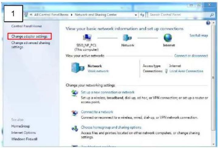
text_image
1 All Control Panel Items ▶ Network and Sharing Center ▶ Search Control Panel Control Panel Home Change adapter settings Change advanced sharing settings View your basic network information and set up connections SISO_NP_PCI (This computer) Network Internet See full map View your active networks Connect or disconnect Network Work network Access type: Internet Connections: Local Area Connection Change your networking settings Set up a new connection or network Set up a wireless, broadband, dial-up, ad hoc, or VPN connection; or set up a router or access point. Connect to a network Connect or reconnect to a wireless, wired, dial-up, or VPN network connection. Choose homegroup and sharing options Access files and printers located on other network computers, or change sharing settings. See also HomeGroup Internet Options Windows Firewall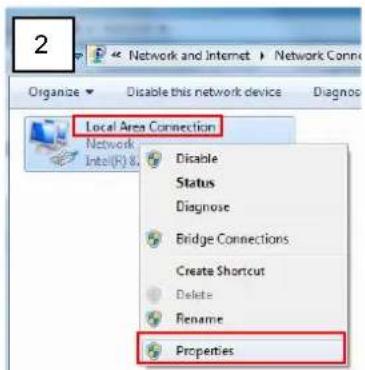
text_image
2 Network and Internet > Network Conn Organize Disable this network device Diagnos Local Area Connection Network Intel(R) & Disable Status Diagnose Bridge Connections Create Shortcut Delete Rename Properties
text_image
Local Area Connection Properties Networking Connect using: Intel(R) 32567LM-3 Gigabit Network Connection Configure... This connection uses the following items: Client for Microsoft Networks VirtualBox Extended Networking Driver QoS Packet Scheduler File and Printer Sharing for Microsoft Networks Internet Protocol Version 6 (TCP/IPv6) Internet Protocol Version 4 (TCP/IPv4) Link-Layer Topology Discovery Mapper I/O Driver Link-Layer Topology Discovery Responder Install Uninstall Properties Description Transmission Control Protocol/Internet Protocol. The default wide area network protocol that provides communication across diverse interconnected networks. OK Cancel
text_image
Internet Protocol Version 4 (TCP/IPv4) Properties generals You can get IP settings assigned automatically if your network supports this capability. Otherwise, you need to ask your network administrator for the appropriate IP settings. Obtain an IP address automatically Use the following IP address: IP address: 192 . 168 . 0 . 99 Subnet mask: 255 . 255 . 255 . 0 Default gateway: . Obtain DNS server address automatically Use the following DNS server addresses: Preferred DNS server: . Alternate DNS server: . Validate settings upon exit Advanced... OK CancelManually adjust the IP addresses of multiple cameras:
If there are more than 1 camera to be used in the same local area network and there is no DHCP server to assign unique IP addresses to each of them, all of the cameras would then have the initial IP address of 192.168.0.100, which is not a proper situation for network devices – all the IP addresses have to be different from each other. The easiest way to assign cameras the IP addresses is by using IP Utility:
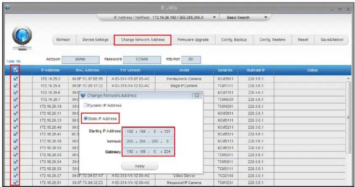
text_image
IP_Utility IP Address / NetMask 172.16.26.192 / 255.255.255.0 Basic Search Refresh Device Settings Change Network Address Firmware Upgrade Config, Backup Config, Restore Reset Save&Robot Total: 56 Account 80min Password 123456 Http Port 80 ✓ P Address MAC Address FW Version Model Serial No Multicast IP Status ✓ 172.16.26.2 00.0F 7C.07 DE.85 A1D-311-V5.07.05-AC Herispheric Camera KCM3911 228.5.6.1 ✓ 172.16.26.4 00.0F 7C.08.17.C2 A1D-310-V4.12.02-AC Mega IP Camera TCM1111 228.5.6.1 ✓ 172.16.26.6 00.0 ✓ 172.16.26.7 00.0 ✓ 172.16.26.10 00.0 ✓ 172.16.26.11 00.0 ✓ 172.10.26.13 00.0 ✓ 172.10.26.40 00.0 ✓ 172.16.26.41 00.0 ✓ 172.16.26.50 00.0 ✓ 172.16.26.52 00.0 ✓ 172.16.26.53 00.0 ✓ 172.16.26.54 00.0 ✓ 172.16.26.55 00.0 ✓ 172.16.26.57 00.0F:7C:04:87:A7 A1D-310-V4.12.05-AC Video Server TCD2100 228.5.6.1 ✓ 172.10.26.01 00.0F:7C:04:32:E3 A1D-310-V4.12.05-AC Megapixel IP Camera TCM1231 228.5.6.1With the procedure shown above, all the cameras will have unique IP addresses, starting from 192.168.0.101. In case there are 20 cameras selected, the last one of the cameras would have the IP 192.168.0.120.
Later, by pressing the "Refresh" button of the IP Utility, you will be able to see the list of cameras with their new IP addresses.

text_image
RefreshPlease note that it is also possible to change the IP addresses manually by using the Web browser. In such case, please plug in only one camera at a time, and change its IP address by using the Web browser before plugging in the next one. This way, the Web browser will not be confused about two devices having the same IP address at the same time.
Access the Camera
Now that the camera and the PC are both having their unique IP addresses and are under the same network segment, it is possible to use the Web browser of the PC to access the camera.
Full functionality is provided only for Microsoft Internet Explorer.
The browser functionality comparison:
| Functionality | Internet Explorer |
| Live Video | Yes |
| Live Video Area Resizable | Yes |
| PTZ Control | Yes |
| Capture the snapshot | Yes |
| Video overlay based configuration(Motion Detection regions, Privacy Mask regions) | Yes |
| All the other configurations | Yes |
When using Internet Explorer browser, the ActiveX control for video stream management will be downloaded from the camera directly – the user just has to accept the use of such control when prompted so. No other third party utilities are required to be installed in such case.
The examples in this manual are based on Internet Explorer browser in order to cover all functions of the camera.
Assuming that the camera's IP address is 192.168.0.100, you can access it by opening the Web browser and typing the following address into the Web browser's address bar:
http://192.168.0.100
Upon successful connection to the camera, the user interface called Web Configurator would appear together with the login page. The HTTP port number was not added behind the IP address since the default HTTP port of the camera is 80, which can be omitted from the address for convenience.

text_image
Http://192.168.0.100 Web Configurator Web Configurator Login Account Password Language English Login ResetDepending on the time you purchased your camera, the manner for initial login may vary. For cameras prompting to enter Account and Password, use the default account and password:
Account: Admin
Password: 123456
For cameras prompting to setup the Root Account and Password, fill up the required fields to do so. Then use this newly setup Account and Password to login to the Web Configurator.

text_image
Set Root Account Name and Password Name Password Confirm Password Language English Apply ResetFor further operations, please refer to the Firmware User Manual.

ACTi
Connecting Vision
Copyright © 2020, ACTi Corporation All Rights Reserved
7F, No. 1, Alley 20, Lane 407, Sec. 2, Ti-Ding Blvd., Neihu District, Taipei, Taiwan 114, R.O.C.
TEL: +886-2-2656-2588 FAX: +886-2-2656-2599
Email: sales@acti.com