Compaq 6531s - Laptop HP - Free user manual and instructions
Find the device manual for free Compaq 6531s HP in PDF.

User questions about Compaq 6531s HP
0 question about this device. Answer the ones you know or ask your own.
Ask a new question about this device
Download the instructions for your Laptop in PDF format for free! Find your manual Compaq 6531s - HP and take your electronic device back in hand. On this page are published all the documents necessary for the use of your device. Compaq 6531s by HP.
USER MANUAL Compaq 6531s HP
HP Compaq 6530s Notebook PC
HP Compaq 6531s Notebook PC
HP Compaq 6535s Notebook PC
Display Replacement Guide
© Copyright 2009 Hewlett-Packard Development Company, L.P.
AMD Athlon, AMD Sempron, and AMD Turion are trademarks of Advanced Micro Devices, Inc. Bluetooth is a trademark owned by its proprietor and used by Hewlett-Packard Company under license. Intel, Core, Celeron are trademarks of Intel Corporation in the United States and other countries. Microsoft, Windows, and Windows Vista are U.S. registered trademarks of Microsoft Corporation. SD Logo is a trademark of its proprietor.
The information contained herein is subject to change without notice. The only warranties for HP products and services are set forth in the express warranty statements accompanying such products and services. Nothing herein should be construed as constituting an additional warranty. HP shall not be liable for technical or editorial errors or omissions contained herein.
First Edition: September 2009
Document Part Number: 592193-001
Safety warning notice
⚠ WARNING! To reduce the possibility of heat-related injuries or of overheating the computer, do not place the computer directly on your lap or obstruct the computer air vents. Use the computer only on a hard, flat surface. Do not allow another hard surface, such as an adjoining optional printer, or a soft surface, such as pillows or rugs or clothing, to block airflow. Also, do not allow the AC adapter to contact the skin or a soft surface, such as pillows or rugs or clothing, during operation. The computer and the AC adapter comply with the user-accessible surface temperature limits defined by the International Standard for Safety of Information Technology Equipment (IEC 60950).
Table of contents
1 Removal and replacement procedures
Preliminary replacement requirements 2
Tools required 2
Service considerations 2
Plastic parts 2
Cables and connectors .... 3
Drive handling 3
Grounding guidelines 4
Equipment guidelines 4
Component replacement procedures 5
Display assembly 5
2 Recycling
Display 17
Index 23
1 Removal and replacement procedures
Preliminary replacement requirements
Tools required
You will need the following tools to complete the removal and replacement procedures:
• Flat-bladed screwdriver
• Magnetic screwdriver
• Phillips P0 and P1 screwdrivers
- Torx T8 screwdriver
Service considerations
The following sections include some of the considerations that you must keep in mind during disassembly and assembly procedures.
NOTE: As you remove each subassembly from the computer, place the subassembly (and all accompanying screws) away from the work area to prevent damage.
Plastic parts
Using excessive force during disassembly and reassembly can damage plastic parts. Use care when handling the plastic parts. Apply pressure only at the points designated in the maintenance instructions.
Cables and connectors
△ CAUTION: When servicing the computer, be sure that cables are placed in their proper locations during the reassembly process. Improper cable placement can damage the computer.
Cables must be handled with extreme care to avoid damage. Apply only the tension required to unseat or seat the cables during removal and insertion. Handle cables by the connector whenever possible. In all cases, avoid bending, twisting, or tearing cables. Be sure that cables are routed in such a way that they cannot be caught or snagged by parts being removed or replaced. Handle flex cables with extreme care; these cables tear easily.
Drive handling
△ CAUTION: Drives are fragile components that must be handled with care. To prevent damage to the computer, damage to a drive, or loss of information, observe these precautions:
Before removing or inserting a hard drive, shut down the computer. If you are unsure whether the computer is off or in Hibernation, turn the computer on, and then shut it down through the operating system.
Before handling a drive, be sure that you are discharged of static electricity. While handling a drive, avoid touching the connector.
Before removing a diskette drive or optical drive, be sure that a diskette or disc is not in the drive and be sure that the optical drive tray is closed.
Handle drives on surfaces covered with at least one inch of shock-proof foam.
Avoid dropping drives from any height onto any surface.
After removing a hard drive, an optical drive, or a diskette drive, place it in a static-proof bag.
Avoid exposing a hard drive to products that have magnetic fields, such as monitors or speakers.
Avoid exposing a drive to temperature extremes or liquids.
If a drive must be mailed, place the drive in a bubble pack mailer or other suitable form of protective packaging and label the package "FRAGILE."
Grounding guidelines
Equipment guidelines
Grounding equipment must include either a wrist strap or a foot strap at a grounded workstation.
- When seated, wear a wrist strap connected to a grounded system. Wrist straps are flexible straps with a minimum of one megohm ± 10% resistance in the ground cords. To provide proper ground, wear a strap snugly against the skin at all times. On grounded mats with banana-plug connectors, use alligator clips to connect a wrist strap.
- When standing, use foot straps and a grounded floor mat. Foot straps (heel, toe, or boot straps) can be used at standing workstations and are compatible with most types of shoes or boots. On conductive floors or dissipative floor mats, use foot straps on both feet with a minimum of one megohm resistance between the operator and ground. To be effective, the conductive strips must be worn in contact with the skin.
The following grounding equipment is recommended to prevent electrostatic damage:
- Antistatic tape
• Antistatic smocks, aprons, and sleeve protectors
• Conductive bins and other assembly or soldering aids
• Nonconductive foam
• Conductive tabletop workstations with ground cords of one megohm resistance
• Static-dissipative tables or floor mats with hard ties to the ground
Field service kits
• Static awareness labels
• Material-handling packages
• Nonconductive plastic bags, tubes, or boxes
• Metal tote boxes
• Electrostatic voltage levels and protective materials
The following table lists the shielding protection provided by antistatic bags and floor mats.
Material Use Voltage protection level
| Antistatic plastic Bags 1,500 V |
| Carbon-loaded plastic Floor mats 7,500 V |
| Metallized laminate Floor mats 5,000 V |
Component replacement procedures
Display assembly
NOTE: All display assembly spare part kits include 2 WLAN antenna transceivers and cables.
| Description Spare part number | |
| For use only with HP Compaq 6535s Notebook PC models | |
| 14.1-inch, WXGA BrightView display assembly with camera | 493155-001 |
| 14.1-inch, WXGA BrightView display assembly 493154-001 | |
| 14.1-inch, WXGA display assembly with camera 493152-001 | |
| 14.1-inch, WXGA display assembly 493151-001 | |
| For use only with HP Compaq 6530s and 6531s Notebook PC models | |
| 14.1-inch, WXGA BrightView display assembly with camera | 491643-001 |
| 14.1-inch, WXGA display assembly with camera 491642-001 | |
| 14.1-inch, WXGA BrightView display assembly 491641-001 | |
| 14.1-inch, WXGA display assembly 491640-001 | |
Remove the display assembly:
- Shut down the computer. If you are unsure whether the computer is off or in Hibernation, turn the computer on, and then shut it down through the operating system.
- Disconnect all external devices connected to the computer.
- Disconnect the power from the computer by first unplugging the power cord from the AC outlet and then unplugging the AC adapter from the computer.
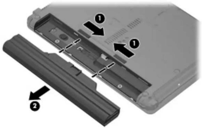
- Turn the computer upside down on a flat surface, with the battery bay toward you.
-
Slide the battery release latches (1) to release the battery.
-
Remove the battery (2) from the computer.
text_image
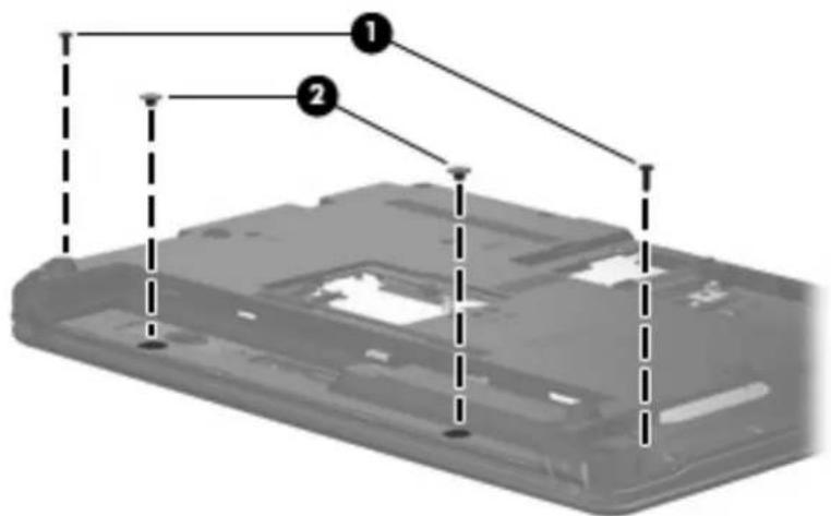
Diagram of a device showing two labeled components (1 and 2) with arrows indicating assembly or disassembly steps.- Remove the following screws:
(1) Two slotted Torx ST8M2.5×7.0 screws
(2) Two Torx T8M2.0×2.0 broadhead (9-mm) screws
text_image
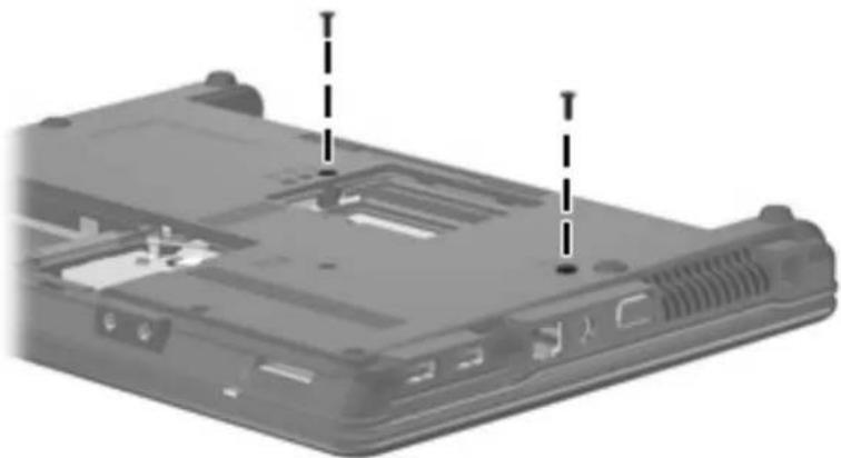
Diagram of a device casing with labeled components, showing numbered parts and dashed alignment lines.- Remove the two slotted Torx ST8M2.5×7.0 screws that secure the keyboard to the computer.
natural_image
Laptop back panel with two dashed arrows pointing to internal components (no text or symbols visible)- Turn the computer display-side up, with the front toward you.
- Open the computer as far as possible.
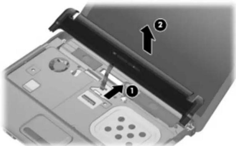
- Lift the switch cover (1) straight up until it disengages from the computer, and slide it back (2) until it rests on the display assembly.

text_image
Laptop keyboard diagram with numbered annotations indicating component placement- Release the zero insertion force (ZIF) connector to which the LED board cable is attached, disconnect the LED board cable from the system board (1), and lift the switch cover up to remove it (2) from the system board.
text_image
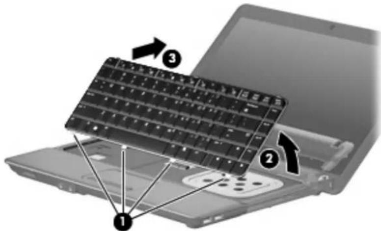
Laptop interior diagram with numbered annotations indicating component locations- To disengage the four tabs (1) on the back of the keyboard from the switch cover, lift up the rear edge of the keyboard (2), and slide it back (3).
text_image
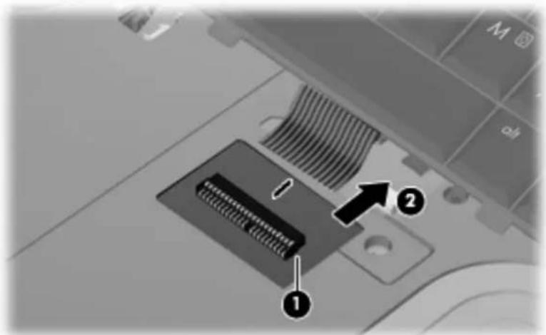
Laptop keyboard diagram with numbered annotations indicating component placement- Release the swinging ZIF connector (1) to which the keyboard cable is attached, and disconnect the keyboard cable (2) from the system board.
text_image
Diagram of a car air vent with labeled components and directional arrows indicating parts 1 and 2.- Remove the keyboard.
- Turn the switch cover over.
- Remove the two Phillips PM2.0×2.0 broadhead screws (1) from the switch cover.
- Remove the LED power button board (2) from the switch cover.

text_image
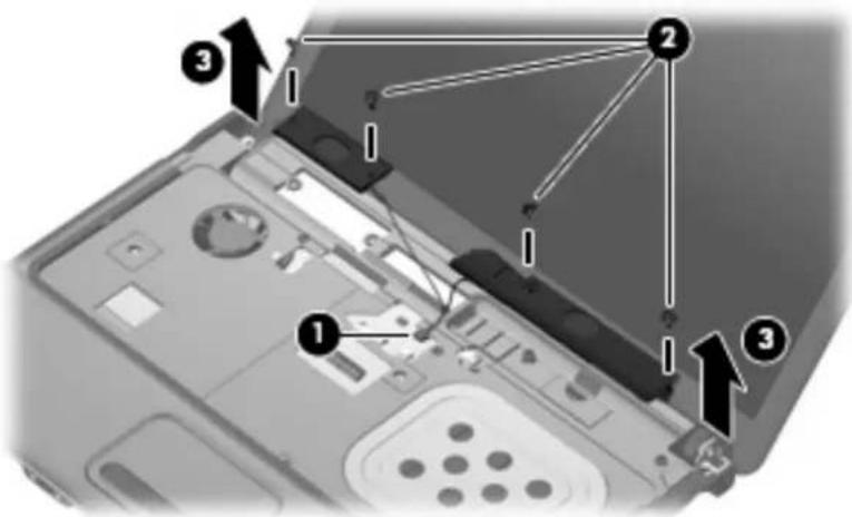
Technical diagram showing a mechanical component with labeled parts and directional arrows- Disconnect the speaker cable (1) from the system board and remove the speaker cable from the clips and routing channel.

NOTE: The two speakers are connected with a single cable.
-
Remove the four Phillips PM2.5×4.0 screws (2) that secure the speakers to the top cover.
-
Remove the speakers (3) from the top cover.
text_image
Laptop interior diagram with numbered annotations pointing to key components- Turn the computer right-side up, with the front toward you.
- Open the computer as far as possible.
- Disconnect the display panel cable (1) from the system board.
△ CAUTION: There is a ground loop off the display panel cable that is secured to the left hinge. Be sure you do not pull or damage the cable.
- Disconnect the camera and microphone module cables (2) from the system board, and then remove the cables from the routing path (3).
- Remove the wireless antenna cables (4) from the clips and routing channels built into the top cover.

text_image
Laptop interior diagram with numbered annotations pointing to components like ventilation, ports, and control panel- Remove the following:
△ CAUTION: The display assembly will be unsupported when the following screws are removed. To prevent damage to the display assembly, support it before removing the screws.
(1) Four slotted Torx ST8M2.5×7.0 screws that secure the display assembly to the computer.
△ CAUTION: There is a ground loop off the display panel cable (2) that is secured to the left hinge. Be sure you do not pull or damage the cable.
(3) Lift the display assembly straight up and remove it.

text_image
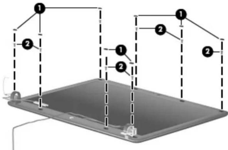
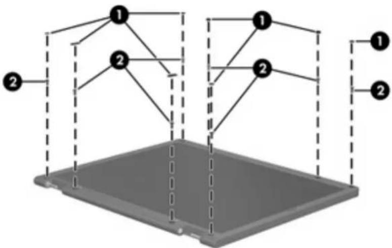
Laptop screen setup diagram with numbered components and labeled parts- If it is necessary to replace the display bezel, display inverter, or display hinges, remove the eight rubber screw covers (1) and the eight Torx T8M2.5×6.0 screws (2) that secure the display bezel to the display assembly. The rubber screw covers are available in the Rubber Kit, spare part numbers 497622-001 (for use only with HP Compaq 6535s Notebook PC models) and 491654-001 (for use only with HP Compaq 6530s and 6531s Notebook PC models).
text_image
Diagram of a device with labeled components and dashed lines indicating connections or paths, marked with numbers 1 and 2.-
Flex the inside edges of the left and right sides (1) and the top and bottom sides (2) of the display bezel until the bezel disengages from the display enclosure.
-
Remove the display bezel (3). The display bezel is available using spare part numbers 497619-001 (for use only with HP Compaq 6535s Notebook PC models without a webcam), 497617-001 (for use only with HP Compaq 6535s Notebook PC models with a webcam), 491636-001 (for use only with HP Compaq 6530s and 6531s Notebook PC models with a webcam), and 491635-001 (for use only with HP Compaq 6530s and 6531s Notebook PC models without a webcam).
text_image
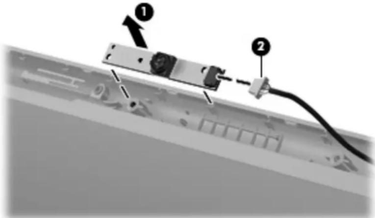
Diagram showing three labeled steps of a mechanical or electrical component with directional arrows indicating motion.- If it is necessary to replace the webcam module from the display enclosure, gently pull the webcam module from the double-sided tape on the display enclosure (1) and disconnect the webcam cable from the module (2). The webcam module can be ordered by using spare part numbers 491630-001 (for use only with HP Compaq 6530s and 6531s Notebook PC models) and 493171-001 (for use only with HP Compaq 6535s Notebook PC models).
text_image
Diagram showing a cable connector with labeled parts, including numbered annotations 1 and 2 pointing to components.
NOTE: To replace the webcam module in the display enclosure, align the holes on the webcam module with the pins on the display enclosure and press onto the double-sided tape.
-
If it is necessary to replace the display inverter, remove the inverter (1) from the display enclosure as far as the display panel cable and the backlight cable will allow.
-
Disconnect the display panel cable (2) and the backlight cable (3) from the display inverter.
text_image
Diagram of a device with labeled components and an upward arrow indicating motion or flow-
Remove the display inverter. The display inverter is available using spare part numbers 497615-001 (for use only with HP Compaq 6535s Notebook PC models) and 491634-001 (for use only with HP Compaq 6530s and 6531s Notebook PC models).
-
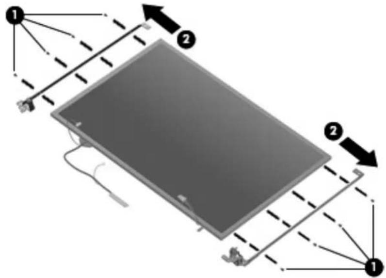
If it is necessary to replace the display hinges, remove the four Torx T8M2.5×5.0 screws (1) that secure the display panel to the display enclosure.
-
Remove the display panel (2).
text_image
Diagram showing two labeled components (1 and 2) of a device with internal wiring and structural elements, likely illustrating a mechanical or electronic assembly.- Remove the four Phillips PM2.0×3.0 screws (1) that secure each display hinge to the display panel.

NOTE: When removing or replacing the eight Phillips screws, be sure to remove or replace them in the same sequence as the numbering found on the display hinges (1–2–3–4).
- Remove the display hinges (2). The left and right display hinges are available in the Bracket Kit, spare part numbers 493170-001 (for use only with HP Compaq 6535s Notebook PC models) and 491639-001 (for use only with HP Compaq 6530s and 6531s Notebook PC models).
text_image
Diagram showing a device with labeled components and directional arrows indicating flow or movement.-
If it is necessary to replace the wireless antenna cables, remove the two Torx T8M2.5×4.0 screws (1) that secure the wireless antenna transceiver to the top cover. The wireless antenna cables are included in the Display Cable Kit, spare part numbers 497620-001 (for use only with HP Compaq 6535s Notebook PC models) and 491637-001 (for use only with HP Compaq 6530s and 6531s Notebook PC models).
-
Remove the wireless antenna (2).
-
Remove the wireless antenna cables (3) from the clips and routing channels built into the top cover.
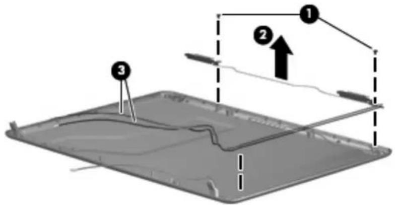
text_image
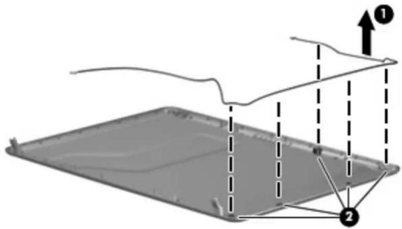
Diagram showing a device with labeled components and directional arrows, likely illustrating a physical or engineering concept.- If it is necessary to replace the webcam cable from the display enclosure, gently pull the webcam cables (1) from the clips and routing channels (2) built into the top cover. The webcam cable is included in the Display Cable Kit, spare part numbers 497620-001 (for use only with HP Compaq 6535s Notebook PC models) and 491637-001 (for use only with HP Compaq 6530s and 6531s Notebook PC models).
text_image
Diagram showing a 3D object with labeled components and directional arrows, likely illustrating a physical or engineering concept.Reverse this procedure to reassemble and install the display assembly.
2 Recycling
Display
⚠ WARNING! The backlight contains mercury. Exercise caution when removing and handling the backlight to avoid damaging this component and causing exposure to the mercury.
△ CAUTION: The procedures in this chapter can result in damage to display components. The only components intended for recycling purposes are the liquid crystal display (LCD) panel and the backlight. When you remove these components, handle them carefully.
NOTE: Materials Disposal. This HP product contains mercury in the backlight in the display assembly that might require special handling at end-of-life. Disposal of mercury may be regulated because of environmental considerations. For disposal or recycling information, contact your local authorities, or see the Electronic Industries Alliance (EIA) Web site at http://www.eiae.org.
This section provides disassembly instructions for the display assembly. The display assembly must be disassembled to gain access to the backlight (1) and the liquid crystal display (LCD) panel (2).

natural_image
Diagram showing two components: a black rectangular base with a thin wire and a curved line, and a gray rectangular panel with a flat top (no text or symbols)NOTE: The procedures provided in this chapter are general disassembly instructions. Specific details, such as screw sizes, quantities, and locations, and component shapes and sizes, can vary from one computer model to another.
Perform the following steps to disassemble the display assembly:
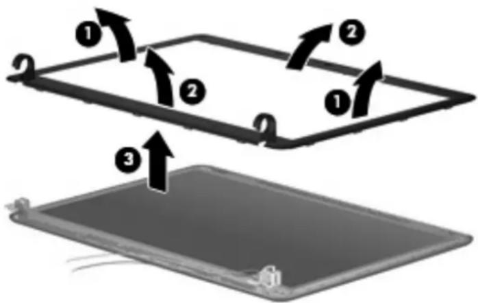
- Remove all screw covers (1) and screws (2) that secure the display bezel to the display assembly.
flowchart
graph TD
    A["1"] --> B["2"]
    C["1"] --> D["2"]
    E["1"] --> F["2"]
    G["1"] --> H["2"]
    I["2"] --> J["1"]
    K["2"] --> L["2"]
-
Lift up and out on the left and right inside edges (1) and the top and bottom inside edges (2) of the display bezel until the bezel disengages from the display assembly.
-
Remove the display bezel (3).

text_image
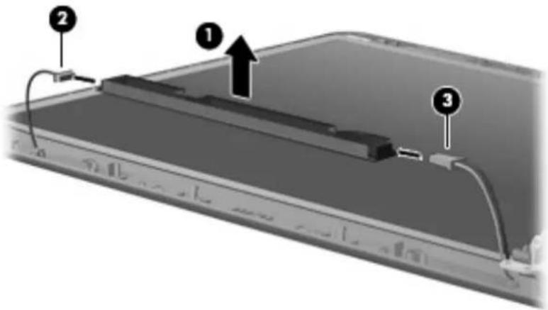
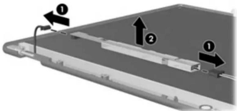
Diagram showing three labeled components (1, 2, 3) with arrows indicating motion or movement on a flat panel surface.- Disconnect all display panel cables (1) from the display inverter and remove the inverter (2).
text_image
Diagram showing a mechanical or electronic component with labeled parts and directional arrows indicating movement or flow.-
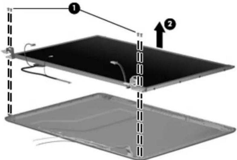
Remove all screws (1) that secure the display panel assembly to the display enclosure.
-
Remove the display panel assembly (2) from the display enclosure.
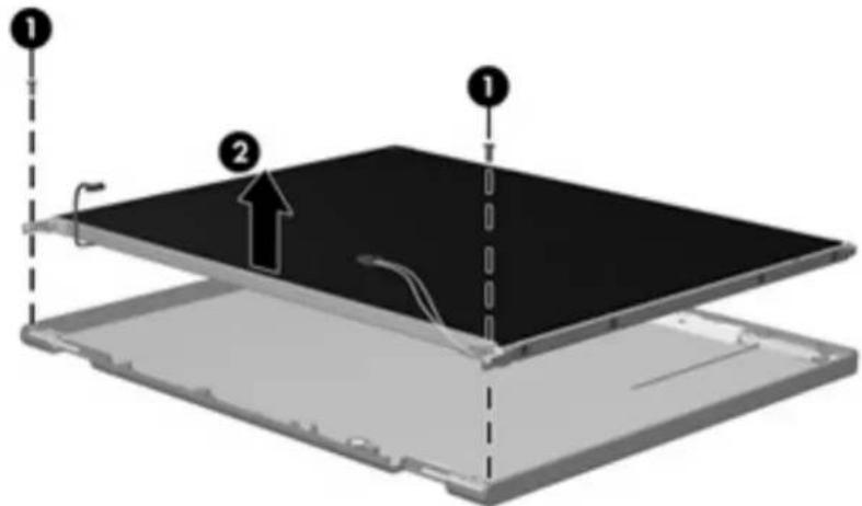
text_image
Diagram of a device with labeled components, showing two numbered parts and a dashed line indicating alignment or assembly.-
Turn the display panel assembly upside down.
-
Remove all screws that secure the display panel frame to the display panel.

natural_image
3D diagram of a rectangular electronic device with internal components and wiring, no visible text or symbols-
Use a sharp-edged tool to cut the tape (1) that secures the sides of the display panel to the display panel frame.
-
Remove the display panel frame (2) from the display panel.
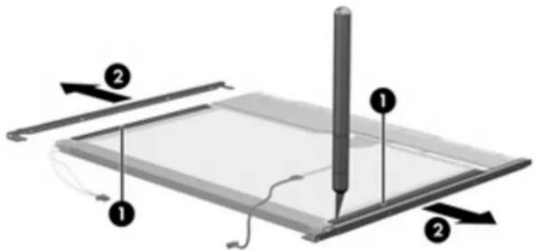
text_image
Diagram of a digital drawing tablet with labeled components and directional arrows indicating movement or orientation.-
Remove the screws (1) that secure the backlight cover to the display panel.
-
Lift the top edge of the backlight cover (2) and swing it outward.

text_image
Diagram showing a device with labeled parts and directional arrows, including numbered annotations 1 and 2.-
Remove the backlight cover.
-
Turn the display panel right-side up.
-
Remove the backlight cables (1) from the clip (2) in the display panel.
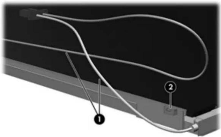
natural_image
Diagram of a cable or wire connection with labeled components (1 and 2), no readable text or symbols present.- Turn the display panel upside down.
⚠ WARNING! The backlight contains mercury. Exercise caution when removing and handling the backlight to avoid damaging this component and causing exposure to the mercury.
- Remove the backlight frame from the display panel.
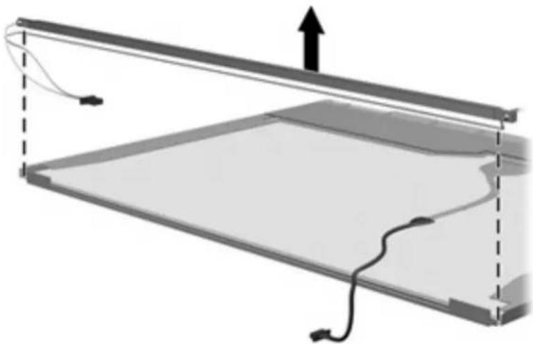
natural_image
Diagram of a mechanical or electrical component with internal structure and upward force arrow (no text or symbols)- Remove the backlight from the backlight frame.

natural_image
Diagram of a mechanical or electrical component with a central rod and attached wires, showing an upward force arrow (no text or symbols present)- Disconnect the display panel cable (1) from the LCD panel.
- Remove the screws (2) that secure the LCD panel to the display rear panel.
- Release the LCD panel (3) from the display rear panel.
- Release the tape (4) that secures the LCD panel to the display rear panel.

text_image
Diagram of a device with numbered components and directional arrows indicating motion or movement- Remove the LCD panel.
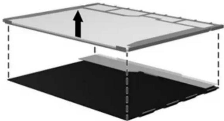
natural_image
Diagram of a layered structure with an upward arrow indicating direction, no text or symbols present- Recycle the LCD panel and backlight.
Index
C
cables, service considerations 3
connectors
service considerations 3
D
diskette drive
precautions 3
display assembly
removal 5
spare part numbers 5
display bezel
removal 11
spare part number 12
display component recycling 17
display hinge
removal 13
spare part number 14
display inverter
removal 12
spare part number 13
display panel, removal 13
drives
preventing damage 3
DVD/CD-RW Combo Drive
precautions 3
DVD±RW and CD-RW Combo
Drive, Double-Layer
precautions 3
G
grounding equipment and
methods 4
H
hard drive
precautions 3
hinge
removal 13
spare part number 14
0
optical drive
precautions 3
P
plastic parts 2
R
removal/replacement
preliminaries 2
procedures 5
S
service considerations 2
static-shielding materials 4
T
tools required 2