DX1C12426-22 - Washing machine Daizuki - Free user manual and instructions
Find the device manual for free DX1C12426-22 Daizuki in PDF.

User questions about DX1C12426-22 Daizuki
0 question about this device. Answer the ones you know or ask your own.
Ask a new question about this device
Download the instructions for your Washing machine in PDF format for free! Find your manual DX1C12426-22 - Daizuki and take your electronic device back in hand. On this page are published all the documents necessary for the use of your device. DX1C12426-22 by Daizuki.
USER MANUAL DX1C12426-22 Daizuki
Owner's Manual & Installation Manual

DAIZUKI®
MODEL DX1C09426-22 DX1C12426-22 DX1C18426-22
natural_image
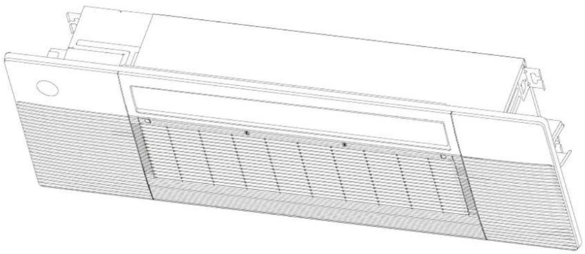
Technical line drawing of a mechanical component with internal grating and mounting brackets (no text or symbols)IMPORTANT NOTE:
- Read this manual carefully before installing or operating your new air conditioning unit. Make sure to save this manual for future reference.
Table of Contents
Safety Precautions ....04
Owner's Manual
Unit Specifications and Features 08
- Unit Parts ......08
- Operating temperature 09
- Features ....10
- Energy Saving Tips ....11
Care and Maintenance ....12
Troubleshooting ....15
Owner's Manual
Accessories ....17
Unit Parts ....19
Indoor Unit Installation 20
- Select installation location ....20
- Indoor Unit Installation....22
- Optimal parts installation ....25
Outdoor Unit Installation....27
- Select installation location ....27
- Install drain joint ....28
- Anchor outdoor unit....28
Drainpipe Installation ....31
Indoor Drainpipe Installation ....31
Refrigerant Piping Connection ....33
Electrical Connections ....36
Air Evacuation ....40
Electrical and Gas Leak Chechs 42
Panel Installation....43
- Prepare and install ceiling ....43
- Panel Installation ....43
- Optimal parts installation....45
Test Run....46
Read Safety Precautions Before Operation and Installation
Incorrect installation due to ignoring instructions can cause serious damage or injury.
The seriousness of potential damage or injuries is classified as either a WARNING or CAUTION.

WARNING
This symbol indicates the possibility of personnel injury or loss of life.

CAUTION
This symbol indicates the possibility of property damage or serious consequences.

WARNING
- This appliance is not intended for use by persons(including children) with reduced physical, sensory or mental capabilities, or lack of experience and knowledge, unless they have been given supervision or instruction concerning use of the appliance by a person responsible for their safety. Children should be supervised to ensure that they do not play with the appliance.

WARNINGS FOR PRODUCT USE
- If an abnormal situation arises (like a burning smell), immediately turn off the unit and disconnect the power. Call your dealer for instructions to avoid electric shock, fire or injury.
- Do not insert fingers, rods or other objects into the air inlet or outlet. This may cause injury, since the fan may be rotating at high speeds.
- Do not use flammable sprays such as hair spray, lacquer or paint near the unit. This may cause fire or combustion.
- Do not operate the air conditioner in places near or around combustible gases. Emitted gas may collect around the unit and cause explosion.
- Do not operate your air conditioner in a wet room such as a bathroom or laundry room. Too much exposure to water can cause electrical components to short circuit.
- Do not expose your body directly to cool air for a prolonged period of time.
- Do not allow children to play with the air conditioner. Children must be supervised around the unit at all times.
- If the air conditioner is used together with burners or other heating devices, thoroughly ventilate the room to avoid oxygen deficiency.
- In certain functional environments, such as kitchens, server rooms, etc., the use of specially designed air-conditioning units is highly recommended.
- Toxic fumes may be produced if the refrigerant in this unit comes into contact with naked flames (such as from a heater, gas stove/burners, or electric appliances).

WARNINGS FOR PRODUCT USE
- Dispose of this unit's packaging carefully, so children cannot play with it. Packaging, especially plastic packaging, can be dangerous, can cause serious injury or death. Screws, staples and other metal packaging components can be sharp and should be disposed of carefully to avoid injury.
- Do not open or remove the unit's panel when the unit is powered on. Touching the unit's internal components while the unit is powered on can lead to electric shocks or injuries caused by moving parts such as the unit's fan.
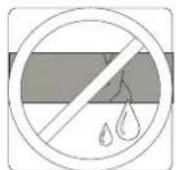
- Do not spray any liquids onto the unit or allow any liquids to drip onto the unit.
- The refrigerant in this unit is safe and should not leak if the system is designed and installed properly. However, if a large amount of refrigerant leaks into a room, the oxygen concentration will decrease rapidly, which can cause serious injury or death. The refrigerant used in this unit is heavier than air, so the danger is greater in basements or other underground spaces. In the event of a refrigerant leak, turn off any devices that produce a naked flame and any heating devices, ventilate the room, and contact your supplier or service engineer immediately.

CLEANING AND MAINTENANCE WARNINGS
- Turn off the device and disconnect the power before cleaning. Failure to do so can cause electrical shock.
- Do not clean the air conditioner with excessive amounts of water
- Do not clean the air conditioner with combustible cleaning agents. Combustible cleaning agents can cause fire or deformation.

CAUTION
- Turn off the air conditioner and disconnect the power if you are not going to use it for a long time.
- Turn off and unplug the unit during storms.
- Make sure that water condensation can drain unhindered from the unit.
- Do not operate the air conditioner with wet hands. This may cause electric shock.
- Do not use device for any other purpose than its intended use.
- Do not climb onto or place objects on top of the outdoor unit.
- Do not allow the air conditioner to operate for long periods of time with doors or windows open, or if the humidity is very high.
- Some parts of the unit are sharp and can cause injury if touched. To prevent injury, when the unit is being serviced, gloves should be worn.

ELECTRICAL WARNINGS
- Only use the specified power cord. If the power cord is damaged, it must be replaced by the manufacturer, its service agent or similarly qualified persons in order to avoid a hazard.

ELECTRICAL WARNINGS
- Do not modify the length of the power supply cord or use an extension cord to power the unit.
- The product must be properly grounded at the time of installation, or electrical shock may occur.
- For all electrical work, follow all local and national wiring standards, regulations, and the Installation Manual. Connect cables tightly, and clamp them securely to prevent external forces from damaging the terminal. Improper electrical connections can overheat and cause fire, and may also cause shock. All electrical connections must be made according to the Electrical Connection Diagram located on the panels of the indoor and outdoor units.
- All wiring must be properly arranged to ensure that the control board cover can close properly. If the control board cover is not closed properly, it can lead to corrosion and cause the connection points on the terminal to heat up, catch fire, or cause electrical shock.
- Disconnection must be incorporated in the fixed wiring in accordance with the wiring rules.
TAKE NOTE OF FUSE SPECIFICATIONS
The air conditioner's circuit board (PCB) is designed with a fuse to provide overcurrent protection. The specifications of the fuse are printed on the circuit board, examples of such are T5A/250VAC and T10A/250VAC.

WARNINGS FOR PRODUCT INSTALLATION
- Installation must be performed by an authorized dealer or specialist. Defective installation can cause water leakage, electrical shock, or fire.
- Installation must be performed according to the installation instructions. Improper installation can cause water leakage, electrical shock, or fire.
(In North America, installation must be performed in accordance with the requirement of NEC and CEC by authorized personnel only.) - Contact an authorized service technician for repair or maintenance of this unit. This appliance shall be installed in accordance with national wiring regulations.
- Only use the included accessories, parts, and specified parts for installation. Using non-standard parts can cause water leakage, electrical shock, fire, and can cause the unit to fail.
- Install the unit in a firm location that can support the unit's weight. If the chosen location can not support the unit's weight, or the installation is not done properly, the unit may drop and cause serious injury and damage
• Install drainage piping according to the instructions in this manual. Improper drainage may cause water damage to your home and property - For units that have an auxiliary electric heater, do not install the unit within 1 meter (3 feet) of any combustible materials
- Do not install the unit in a location that may be exposed to combustible gas leaks. If combustible gas accumulates around the unit, it may cause fire.
- Do not turn on the power until all work has been completed.

ELECTRICAL WARNINGS
- When moving or relocating the air conditioner, consult experienced service technicians for disconnection and reinstallation of the unit.
- How to install the appliance to its support, please read the information for details in "indoor unit installation" and "outdoor unit installation" sections.
Unit Specifications and Features
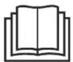
Unit Parts
NOTE: Illustrations in this manual are for explanatory purposes.
The actual shape of your indoor unit may be slightly different. The actual shape shall prevail.
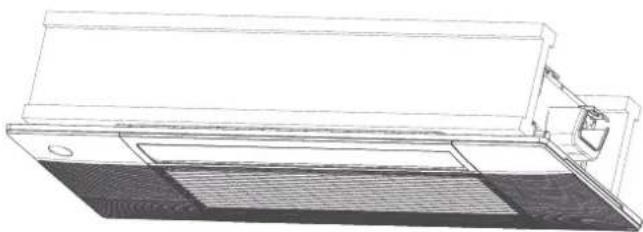
text_image
Air Intake Grille Air Filter Air Vane Display Panel
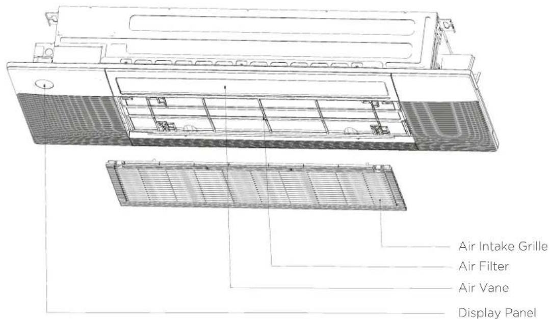
text_image
Air Outlet Air Inlet Electronic CoDisplay Panel
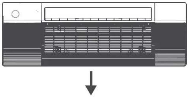
The display panel has one type and the appearance of the type is shown below.
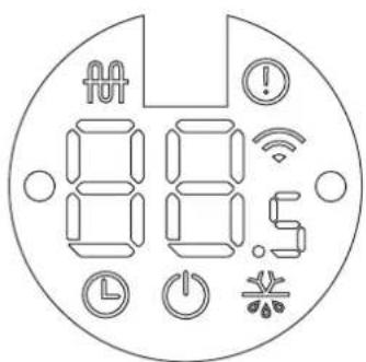
text_image
88.05“” when electric heating feature is activated. (not available for this unit)
“L” when TIMER is set.
"⏻" when the unit is on.
“ Ⓞ ” Alarm indicator.
“” when wireless control feature is activated. (some units)
“*” when pre-heating/defrost feature is activated.
"88s" displays temperature, operation feature and error codes:
"FP" when 8°C heating feature is turned on.
“CL” when active clean feature is turned on.
"RP" when WiFi module enters AP mode. (some units)
"FC" when forced cooling feature is turned on.
Operating Temperature
When your air conditioner is used outside of the following temperature ranges, certain safety protection features may activate and cause the unit to disable.
Inverter Split Type
| COOL mode | HEAT mode DRY mode | ||
| Room Temperature | 17°C - 32°C62°F - 90°F | 0°C - 30°C32°F - 90°F | 10°C - 32°C50°F - 90°F |
| Outdoor Temperature (Energy Star / DXFM Series) | -25°C - 50°C-13°F - 122°F | -25°C - 24°C-13°F - 75.2°F | 0°C - 50°C32°F - 122°F |
| Outdoor Temperature (Hyper Heat / DXFM-H Series) | -30°C - 50°C-22°F - 122°F(for models with low temp. cooling systems.) | -30°C - 24°C-22°F - 75.2°F | |
For Outdoor Units With Basepan Heater or Crankcase Heater
When outside temperature is below 0^(32^) , we strongly recommend keeping the unit plugged in at all times to ensure smooth ongoing performance.
NOTICE
Room relative humidity less than 80%. If the air conditioner operates in excess of this figure, the surface of the air conditioner may attract condensation. Please set the vertical air flow louver to its maximum angle (vertically to the floor), and set HIGH fan mode,
To further optimize the performance of your unit, do the following:
- Keep doors and windows closed.
- Limit energy usage by using TIMER ON and TIMER OFF functions.
- Do not block air inlets or outlets.
- Regularly inspect and clean air filters.
Features
Default Setting
When the air conditioner restarts after a power failure, it will default to the factory settings (AUTO mode, AUTO fan, 24°C (76°F)). This may cause inconsistencies on the remote control and unit panel. Use your remote control to update the status.
Auto-Restart
In case of power failure, the system will immediately stop. When power returns, the Operation light on the indoor unit will flash. To restart the unit, press the ON/OFF button on the remote control. If the system has an auto restart function, the unit will restart using the same settings.
Three-minute protection feature
A protection feature prevents the air conditioner from being activated for approximately 3 minutes when it restarts immediately after operation.
Louver Angle Memory Function
Some models are designed with a louver angle memory function. When the unit restarts after a power failure, the angle of the horizontal louvers will automatically return to the previous position.
The angle of the horizontal louver should not be set too small as condensation may form and drip into the machine. To reset the louver, press the manual button, which will reset the horizontal louver settings.
Refrigerant Leak Detection System
(Multi-Zone Systems models do not have this function)
In the event of a refrigerant leak, the LED DISPLAY will display refrigerant leak error code and the LED indicator light will flash.
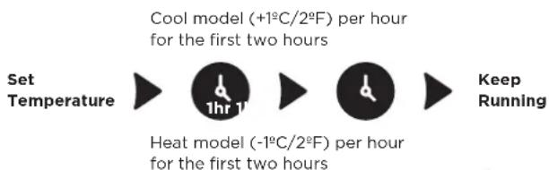
Sleep Operation
The SLEEP function is used to decrease energy use while you sleep (and don't need the same temperature settings to stay comfortable). This function can only be activated via remote control. And the Sleep function is not available in FAN or DRY mode.
Press the SLEEP button when you are ready to go to sleep. When in COOL mode, the unit will increase the temperature by 1^ C ( 2^ F) after 1 hour, and will increase an additional 1^ C ( 2^ F) after another hour.
When in HEAT mode, the unit will decrease the temperature by 1^ C ( 2^ F) after 1 hour, and will decrease an additional 1^ C ( 2^ F) after another hour.
The sleep feature will stop after 8 hours and the system will keep running with final situation.
SLEEP Operation
flowchart
graph LR
    A["Set Temperature"] --> B["1hr 1"]
    B --> C["Heat model (-1°C/2°F) per hour for the first two hours"]
    C --> D["Keep Running"]

saving energy during sleep

Active Clean function (Multi-Zone Systems models do not have this function)
The Active Clean Technology washes away dust when it adheres to the heat exchanger by automatically freezing and then rapidly thawing the frost. A “pi-pi” sound will be heard. The Active clean operation is used to produce more condensed water to improve the cleaning effect, and the cold air will blow out. After cleaning, the internal wind wheel then keeps operating with hot air to blow-dry the evaporator, thus keeping the inside clean.
- When this function is turned on, the indoor unit display window appears "CL", after 20 to 130 minutes, the unit will turn off automatically and cancel Active Clean function.
- For some units, the system will start high temperature cleaning process, and the temperature of air outlet is very high.
Please keep away from it. And this would lead to the rising of the room temperature .horizontal louver settings.
Lifting panel operation
In the stand-by mode, press the "Mode" and "Down" buttons for 3 seconds at the same time, the remote controller enters the setting panel state, and the remote controller displays "F2". When setting the panel status, press the "Up" or "Down" buttons of the remote controller to control the rise or fall of the grille, and press any other button to exit the setting.
The up and down height of the panel can reach a maximum of 1.5 meters. During the decline, if the grille is raised by the obstacles, it will stop. During the ascending process, if the grille is blocked and does not rise to the correct height or a finger is pinched, it will automatically descend after a period of time and then ascend. If the grille is bocked for the third times, then the display panel will report an error and prompt for manual processing.
Breeze Away
This feature avoids direct air flow blowing on the body and make you feel indulging in silky coolness.
Energy Saving Tips
- DO NOT set the unit to excessive temperature levels.
- While cooling, close the curtains to avoid direct sunlight.
- Doors and windows should be kept closed to keep cool or warm air in the room. • DO NOT place objects near the air inlet and outlet of the unit.
- Clean the air filter every two weeks.
- Adjust louvers properly and avoid direct airflow.
- Closing curtains during heating also helps keep the heat in.
- Doors and windows should be kept closed.
Care and Maintenance
Cleaning Your Indoor Unit

BEFORE CLEANING OR MAINTENANCE
Remember to disconnect the power before cleaning or maintenance, except for cleaning air filter. Turn the curcuit breaker of the indoor unit to off is not a kind of power disconnection
- Contact an authorized service technician for repair or maintenance. Improper repair and maintenance may cause water leakage, electrical shock, or fire, and may void your warranty.
- DO NOT substitute a blown fuse with a higher or lower amperage rating fuse, as this may cause circuit damage or an electrical fire.
• Make sure the drain hose is set up according to the instructions. Failure to do so could cause leakage and result in personal property damage, fire and electric shock.
• Make sure that all wires are connected properly. Failure to connect wires according to instructions can result in electrical shock or fire.

CAUTION
- Only use a soft, dry cloth to wipe the unit clean. If the unit is especially dirty, you can use a clothsoaked in warm water to wipe it clean.
- Do not use chemicals or chemically treated cloths to clean the unit.
- Do not use benzene, paint thinner, polishing powder or other solvents to clean the unit. They can cause the plastic surface to crack or deform.
- Do not use water hotter than 40^ (104°F) to clean the front panel. This can cause the panel to deform or become discolored.
- DO NOT wash the unit under running water. Doing so creates an electrical hazard. Clean the unit using a damp, lint-free cloth and neutral detergent. Dry the unit with a dry, lint-free cloth.

WARNING: DO NOT REMOVE OR CLEAN THE FILTER BY YOURSELF
Removing and cleaning the filter can be dangerous. Removal and maintenance must be performed by a certified technician.
Cleaning Your Air Filter
The filter prevents dust and other particles from entering the indoor unit. Dust buildup can reduce the efficiency of the air conditioner. For optimum efficiency, clean the air filter every two weeks or more frequently if you live in a dusty area. Replace the filter with a new one if it's heavily clogged and cannot be cleaned.
NOTICE
In households with animals, you will have to periodically wipe down the grille to prevent animal hair blocking airflow.
Model A
- In the stand-by mode, press the "MODE" and "DOWN" buttons on the remote controller at the same time for 3 seconds, the remote controller enters the panel-setting state, the remote controller displays "F2".
- Then press "DOWN" button on the remote controller, the air grille automatically goes down. When it stops, pick up the air filter.

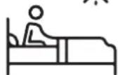
natural_image
Technical line drawing of a device chassis with mounting brackets and internal compartments (no text or symbols)a. Hold the upper edge of the filter with both hands. Gently turn and lift until the upper edge is free from the wire rope.
b. Lift the filter and move it forward slightly until the filter is separated from the 4 wire ropes.
c. Move the filter to the right until it is separated from the air grille, and then the filter can be taken out.
text_image
Technical diagram of a battery pack assembly with labeled components and directional arrowsModel B
- Press the circular positon to open the two screw covers, then remove the two screws.
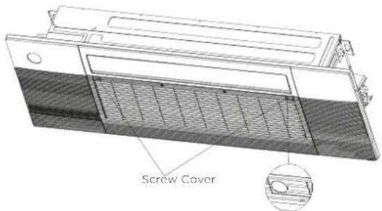
text_image
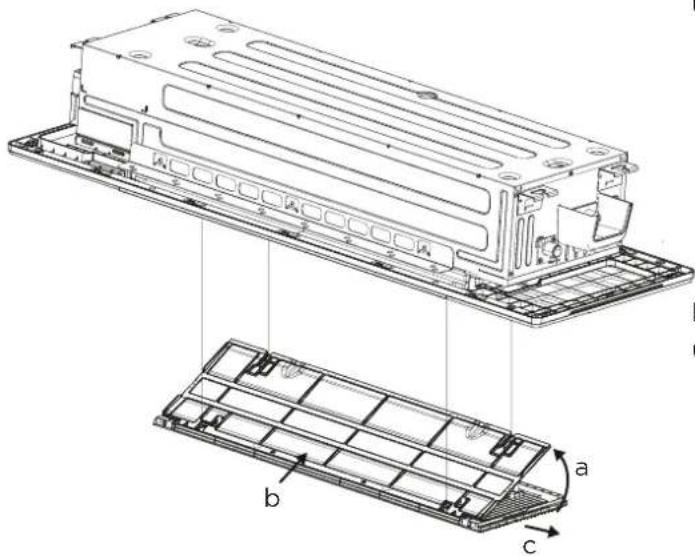
Screw Cover- Hold and open the air grille, then take out the air filter.

text_image
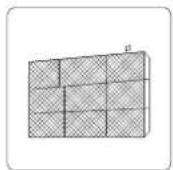
Air Filter- Clean the air filter
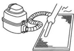
Dust will accumulate on the filter along with the unit operation, and need to be removed from the filter, or the unit would not function effectively. Clean the filter every two weeks when you use the unit regularly. Clean the air filter with a vacuum cleaner or water.
a. The air intake side should face up when using a vacuum cleaner.
natural_image
Line drawing of a vacuum cleaner connected to a surface finisher (no text or symbols)b. The air intake side should face down when using clean water.

natural_image
Simple line drawing of a hand washing a plate with a faucet (no text or symbols)For excessive dusts, use a soft brush and natural detergent to clean it and dry in a cool place.

CAUTION
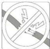
- Do not dry out the air filter under direct sunshine or with fire.
-
The air filter should be installed before the unit body installation.
-
Re-install the air filter.
- Press "UP" button on the remote controller to reset the air grille. (Applicable to model A) Re-install the air grille by fixing the two screws and close the two screw covers. (Applicable to model B)

CAUTION
- Before changing the filter or cleaning, turn off the unit.
- When removing filter, do not touch metal parts in the unit. The sharp metal edges can hurt you.
- Do not use water to clean the inside of the indoor unit. This can destroy insulation and cause electrical shock.
- Do not expose filter to direct sunlight when drying. This can shrink the filter.
- Any maintenance and cleaning of outdoor unit should be performed by an authorized dealer or a licensed service provider.
- Any unit repairs should be performed by an authorized dealer or a licensed service provider.
- When the air grille is rising, please do not hinder the grille from rising with your hands or other objects.
- Please do not pull the wire rope, if necessary, please contact the local customer service team.
Maintenance - Long Periods of Non-Use
If you plan not to use your air conditioner for an extended period of time, do the following:

Clean all filters

Turn on FAN function until unit dries out completely

Turn off the unit and disconnect the power
Maintenance - Pre-Season Inspection
After long periods of non-use, or before periods of frequent use, do the following:
Check for
damaged wires
Clean all filters
Check for leaks
natural_image
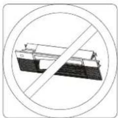
Prohibition symbol of a bench with diagonal line crossing through it, enclosed in a circle (no text or numbers)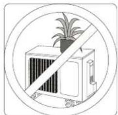
natural_image
Diagram of a potted plant inside a rectangular chamber with diagonal lines indicating prohibition (no text or symbols)Make sure nothing is blocking all air inlets and outlets

SAFETY PRECAUTIONS
If any of the following conditions occurs, turn off your unit immediately!
- The power cord is damaged or abnormally warm.
- You smell a burning odor.
• The unit emits loud or abnormal sounds. - A power fuse blows or the circuit breaker frequently trips. • Water or other objects fall into or out of the unit.
DO NOT ATTEMPT TO FIX THESE YOURSELF! CONTACT AN AUTHORIZED SERVICE PROVIDER IMMEDIATELY!
Common Issues
The following problems are not a malfunction and in most situations will not require repairs.
| Possible CausesIssue | |
| Unit does not turn on when pressing ON/OFF button | The Unit has a 3-minute protection feature that prevents the unit from overloading. The unit cannot be restarted within three minutes of being turned off. |
| Cooling and Heating Models: If the Operation light and PRE-DEF (Pre-heating/ Defrost) indicators are lit up, the outdoor temperature is too cold and the unit's anti-cold wind is activated in order to defrost the unit. | |
| In Cooling-only Models: If the "Fan Only" indicator is lit up, the outdoor temperature is too cold and the unit's anti-freeze protection is activated in order to defrost the unit. | |
| Unit does not turn on when pressing ON/OFF button | The unit may change its setting to prevent frost from forming on the unit. Once the temperature increases, the unit will start operating in the previously selected mode again. |
| The set temperature has been reached, at which point the unit turns off the compressor. The unit will continue operating when the temperature fluctuates again. | |
| The indoor unit emits white mist | In humid regions, a large temperature difference between the room's air and the conditioned air can cause white mist. |
| Both the indoor and outdoor units emit white mist | When the unit restarts in HEAT mode after defrosting, white mist may be emitted due to moisture generated from the defrosting process. |
| The indoor unit makes noises | A squeaking sound is heard when the system is OFF or in COOL mode. The noise is also heard when the drain pump (optional) is in operation. |
| A squeaking sound may occur after running the unit in HEAT mode due to expansion and contraction of the unit's plastic parts. | |
| Both the indoor and outdoor units make noises | Low hissing sound during operation: This is normal and is caused by refrigerant gas flowing through both indoor and outdoor units. |
| Low hissing sound when the system starts, has just stopped running, or is defrosting: This noise is normal and is caused by the refrigerant gas stopping or changing direction. | |
| Squeaking sound: Normal expansion and contraction of plastic and metal parts caused by temperature changes during operation can cause squeaking noises. | |
| The outdoor unit makes noises | The unit will make different sounds based on its current operating mode. |
| Dust is emitted from either the indoor or outdoor unit | The unit may accumulate dust during extended periods of non-use, which will be emitted when the unit is turned on. This can be mitigated by covering the unit during long periods of inactivity. |
| The unit emits a bad odor | The unit may absorb odors from the environment (such as furniture, cooking, cigarettes, etc.) which will be emitted during operations. |
| The unit's filters have become moldy and should be cleaned. | |
| The fan of the outdoor unit does not operate | During operation, the fan speed is controlled to optimize product operation. |
NOTICE
If problem persists, contact a local dealer or your nearest customer service center.
Provide them with a detailed description of the unit malfunction as well as your model number.
Troubleshooting
When troubles occur, please check the following points before contacting a repair company.
| Possible Causes SolutionProblem | ||
| Poor Cooling Performance | Temperature setting may be higher than ambient room temperature | Lower the temperature setting |
| The heat exchanger on the indoor or outdoor unit is dirty | Clean the affected heat exchanger | |
| The air filter is dirty | Remove the filter and clean it according to instructions | |
| The air inlet or outlet of either unit is blocked | Turn the unit off, remove the obstruction and turn it back on | |
| Doors and windows are open | Make sure that all doors and windows are closed while operating the unit | |
| Excessive heat is generated by sunlight | Close windows and curtains during periods of high heat or bright sunshine | |
| Too many sources of heat in the room (people, computers, electronics, etc.) | Reduce amount of heat sources | |
| Low refrigerant due to leak or long-term use | Check for leaks, re-seal if necessary and top off refrigerant | |
| The unit is not working | Power failure | Wait for the power to be restored |
| The power is turned off | Turn on the power | |
| The fuse is burned out | Replace the fuse | |
| The Unit's 3-minute protection has been activated | Wait three minutes after restarting the unit | |
| Timer is activated | Turn timer off | |
| The unit starts and stops frequently | There's too much or too little refrigerant in the system | Check for leaks and recharge the system with refrigerant |
| Incompressible gas or moisture has entered the system | Evacuate and recharge the system with refrigerant | |
| System circuit is blocked | Determine which circuit is blocked and replace the malfunctioning piece of equipment | |
| The compressor is broken Replace the compressor | ||
| The voltage is too high or too low Install a manostat to regulate the voltage | ||
| Poor heating performance | Cold air is entering through doors and windows | Make sure that all doors and windows are closed during use |
| Low refrigerant due to leak or long-term use | Check for leaks, re-seal if necessary and top off refrigerant | |
Accessories
The air conditioning system comes with the following accessories. Use all of the installation parts and accessories to install the air conditioner. Improper installation may result in water leakage, electrical shock and fire, or equipment failure.
Verify that the air conditioner includes the following accessories.
| Shape Qty(pc)Name | |||
| Manual 1 | [c7T5] | ||
| Installation cardboard template |  | 1 | |
| Remote controller |  | 1 | |
| AAA Battery |  | 2 | |
Accessories
| Shape Qty(pc)Name | |||
| Cable tie |  | 6 | |
| Drainpipe adaptor | 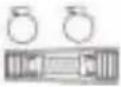 | 1 | |
| Screw kits(ST8*50, M4*22, ST3.9*16, ST4.8*12,ST3.9*10) |  | 1(8,8,2,2,3) | |
| Water receiver |  | 1 | |
| Seal |  | 1 | |
| Drain joint |  | 1 | |
| Wire controller (optional) |  | 1 | |
| Rubber ring |  | 1 | |
| WiFi controller (optional) |  | 1 | |
| Panel |  | 1 | |
| Copper nut |  | 1 | |
Qty(pc) NoteName
| Connecting pipe assembly | Liquid side | 6.35(1/4in) | To purchase based on actual project requirements. | Parts you must purchase separately.Consult the dealer about the proper pipe size of the unit you purchased. |
| Gas side | 9.52(3/8in) | |||
| 12.7(1/2in) |
Unit Parts
NOTICE
The installation must be performed in accordance with the requirement of local and national standards. The installation may be slightly different in different areas.
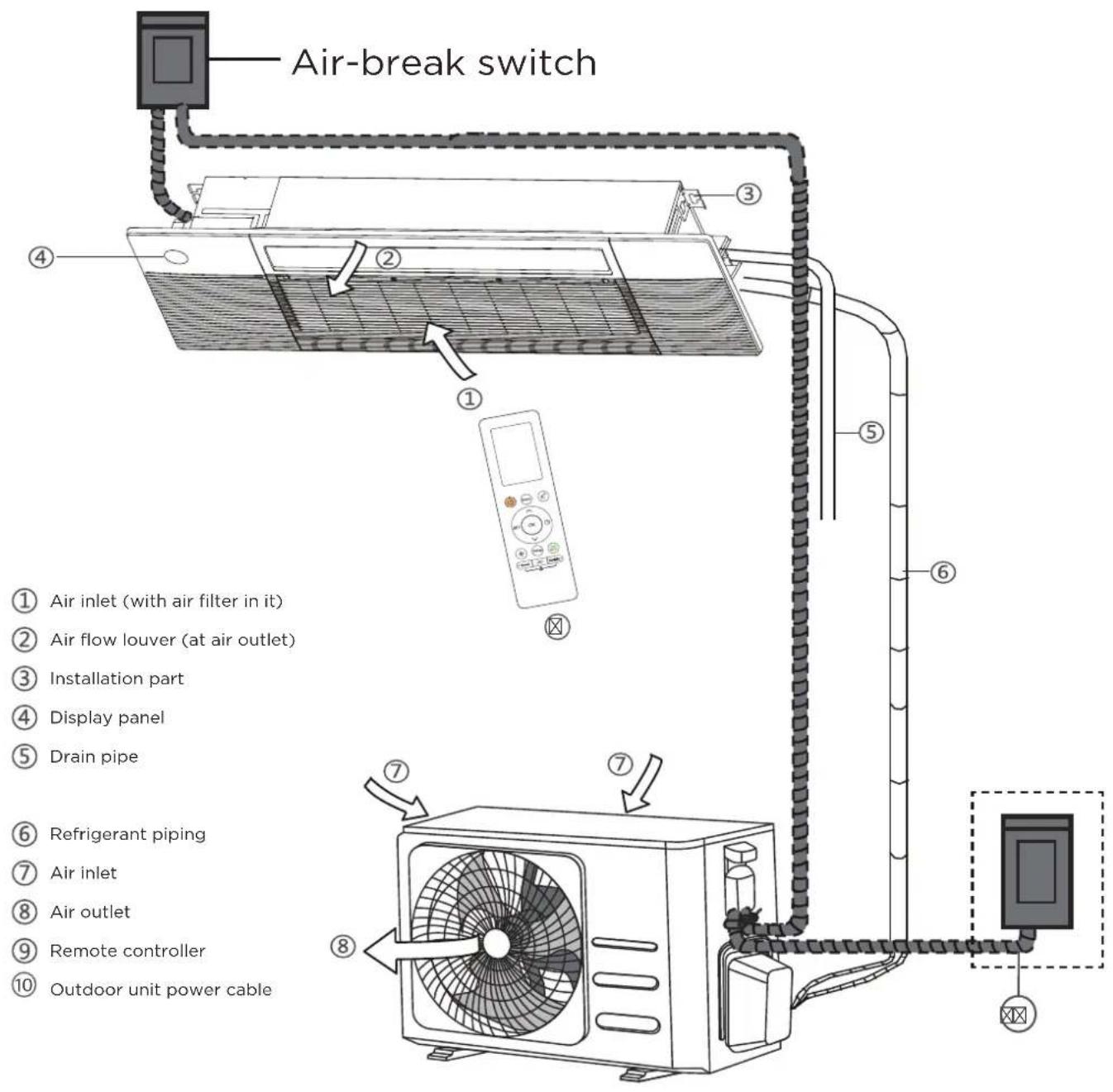
text_image
Air-break switch ① Air inlet (with air filter in it) ② Air flow louver (at air outlet) ③ Installation part ④ Display panel ⑤ Drain pipe ⑥ Refrigerant piping ⑦ Air inlet ⑧ Air outlet ⑨ Remote controller ⑩ Outdoor unit power cableNOTE ON ILLUSTRATIONS
Illustrations in this manual are for explanatory purposes.
The actual shape of your indoor unit may be slightly different. The actual shape shall prevail.
Indoor Unit Installation
NOTICE
Panel installation should be performed after wiring and piping have been completed.
Before Installation
- Determine the route to move the unit to the installation site.
- First unseal and unpack the unit. Then, hold the seats of the hanger (4 pcs) to move the unit. Refrain from exerting force on other parts of the unit, especially the refrigerant piping, water discharge piping, and the plastic parts.
Step 1: Select installation location
Before installing the indoor unit, you must choose an appropriate location. The following are standards that will help you choose an appropriate location for the unit.
Proper installation locations meet the following standards:
√ Enough room exists for installation and maintenance.
√ Enough room exists for the connecting the pipe and drainpipe.
√ The ceiling is horizontal and its structure can sustain the weight of the indoor unit.
√ The air inlet and outlet are not blocked.
√ The airflow can fill the entire room.
√ There is no direct radiation from heaters
DO NOT install unit in the following locations:
Areas with oil drilling or fracking
Coastal areas with high salt content in the air
☒ Areas with caustic gases in the air, such as hot springs
Areas that experience power fluctuations, such as factories
Enclosed spaces, such as cabinets
Kitchens that use natural gas
Areas with strong electromagnetic waves
Areas that store flammable materials or gas
Rooms with high humidity, such as bathrooms or laundry rooms
Installation place
(unit: mm/inch)

text_image
Roof Wall ≥225mm(8.86 in) 220mm(8.66 in) ≥500mm(19.69 in) ≥500mm(19.69 in) Ceiling ≤16mm(5/8 in) Ceiling hole ≥2500mm(98.43 in) GroundInstallation place
(unit: mm/inch)
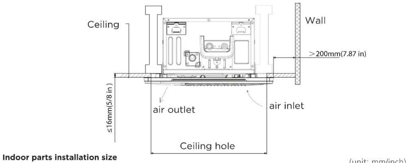
text_image
Ceiling ≤16mm(5/8 in) air outlet Ceiling hole air inlet Wall >200mm(7.87 in) Indoor parts installation size (unit: mm/inch)
text_image
423mm (16.65in) 335mm(13.19in) 205mm(8.07in) 1105mm(43.5in) 250mm(9.84in) 475mm(18.4in) 1360mm(53.54in)Step 2: Indoor Unit Installation
Make sure that only specified components are used for the installation works.
- Connect wire to indoor air handler
Model A: with circuit breaker
- Remove the pre-cutting cover on the circuit breaker box.
natural_image
Technical line drawing of an electronic device interior with circuitry and components (no text or symbols)Pre-cutting cover
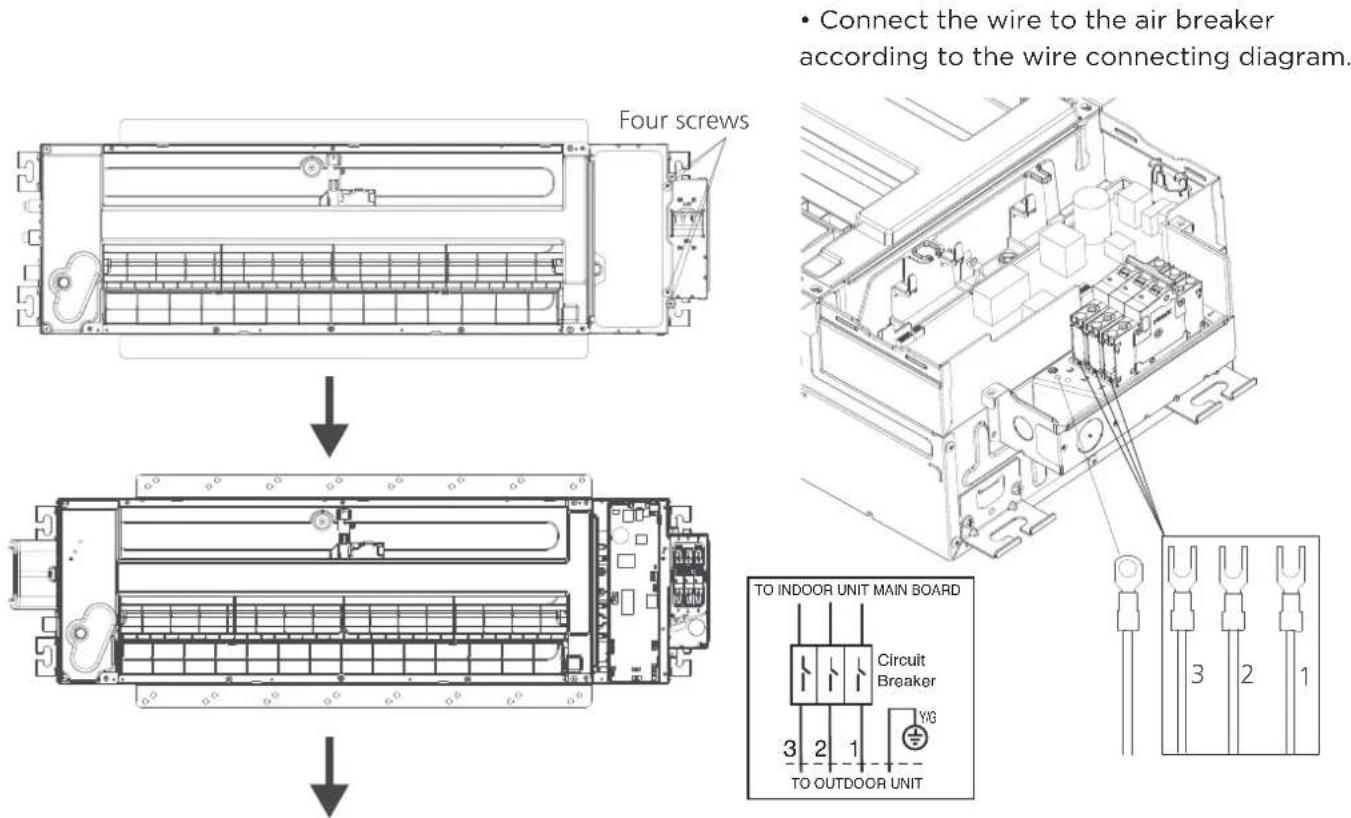
- Connect the wire to the air breaker according to the wire connecting diagram.

WARNING
The ground wire should be tighten firmly without loosening.
- Fasten and fix the wire body with a tie.

natural_image
Technical line drawing of an electronic device casing with internal components and mounting brackets (no text or symbols)Fasten and fix the wire body with a tie.
Model B: with terminal
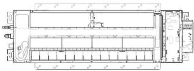
- Remove the four screws to open the indoor control box and terminal box.
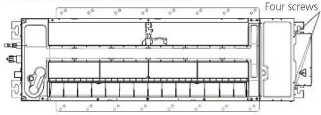
text_image
Four screws
natural_image
Architectural floor plan of a multi-level building with structural layout and equipment (no text or labels)
• Install the circuit breaker cover by fixing the two screws.
text_image
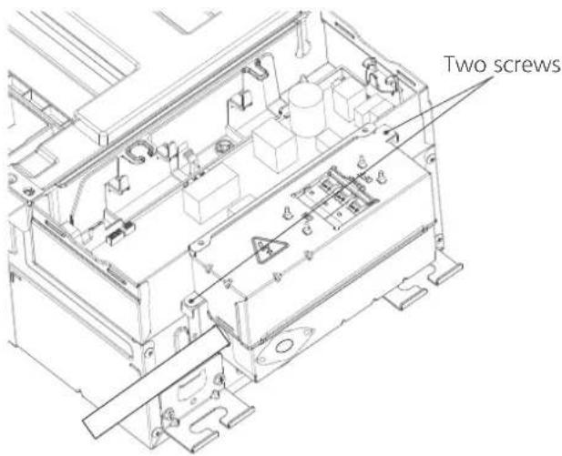
Two screws- Remove the pre-cutting cover on the terminal box. Remove the two screws, then take out the clip

text_image
Pre-cutting cover Two screws- Connect the wire to the terminal according to the wire connecting diagram.
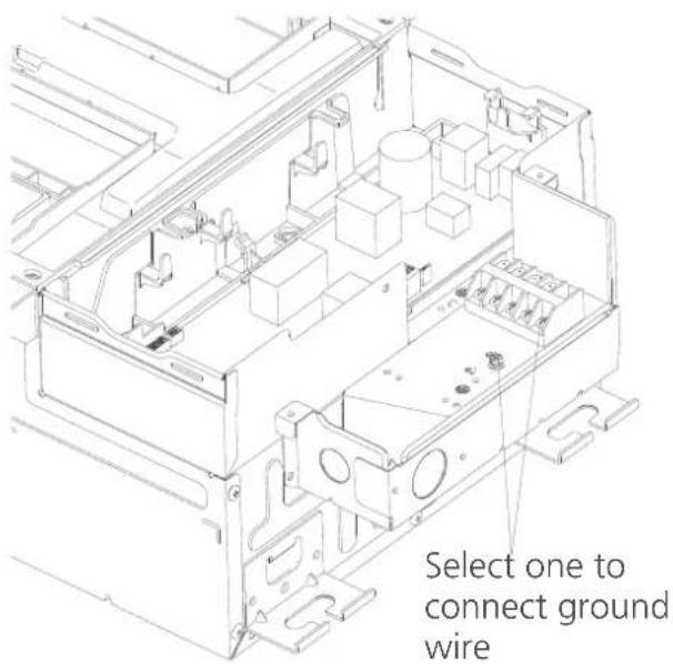
text_image
Select one to connect ground wire• Install the terminal cover by fixing the two screws.
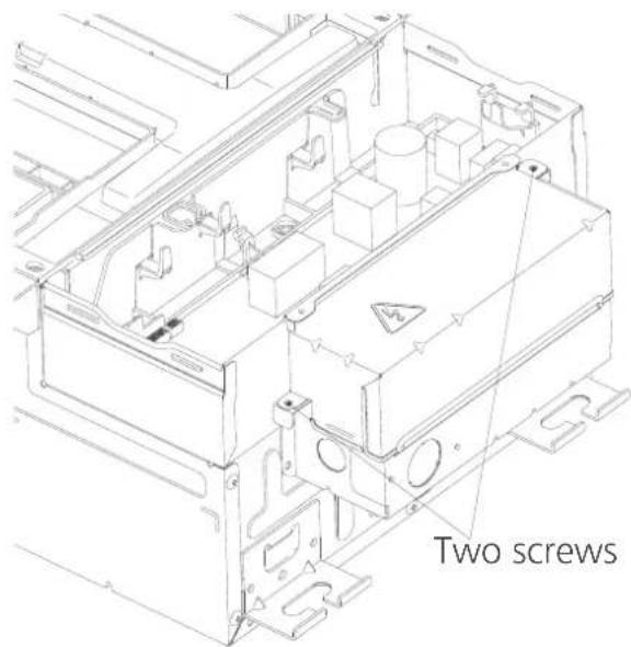
text_image
Two screws2. Install the indoor air handler
NOTICE
After you have finished installing the main body, when choosing where to start, determine the direction of the pipes to be drawn out. Especially in cases where there is a ceiling involved, align the refrigerant pipes, drain pipes, and indoor and outdoor lines with their connection points before mounting the unit.
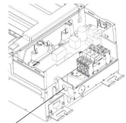
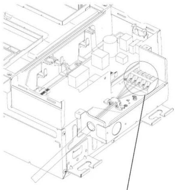
• Fix the wire with the clip by using the two screws.
natural_image
Technical line drawing of an electronic device casing with internal components and a magnified inset showing internal structure (no text or symbols)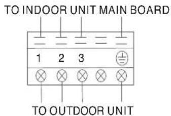
text_image
TO INDOOR UNIT MAIN BOARD 1 2 3 TO OUTDOOR UNIT• After you selecting an installation location, drill a hole with the diameter of 6mm or less into the roof beam based on the layout of the installation board (accessory Installation cardboard template). After drilling the hole, remove the installation board.
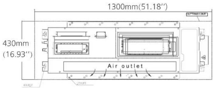
text_image
1300mm(51.18'') 430mm (16.93'') Air outletInstallation cardboard template
- Align the refrigerant pipes, drain pipes with their connection points before mounting the unit.
Mount the indoor unit with at least two people to lift and secure it then fix the unit body to the roof beam by using 6× ST8.0*50 screws.
Make sure that the screws do not come loose.
Make sure you verify the size and positions of the opening in the ceiling before you do so.
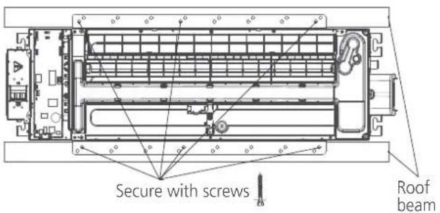
text_image
Secure with screws Roof beamNOTICE
Eight ST8.0*50 screws are supplied, two of which are spare.

WARNING
The unit body must be completely aligned with the hole. Ensure that the unit and the hole are the same size before moving on. Ensure that the indoor unit is horizontal after installation.
Step 3: Optional parts Installation
Wire controller
For the function introduction, operation instruction and installation, please refer to the installation and owner's manual of wire controller. However, for this machine, please following the steps for wire connection.
NOTICE
If you choose this configuration, it is recommended that installing this wire controller during the step of indoor unit installation.
- Remove the specific pre-cutting cover on the circuit breaker box.
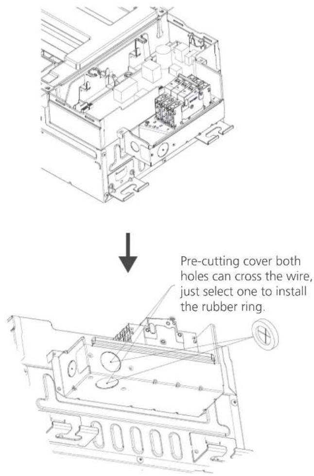
text_image
Pre-cutting cover both holes can cross the wire, just select one to install the rubber ring.- Connecting the wire from the control box.

text_image
To CCM Comm.Bus X Y E CN3 TO 485 WIRE CONTROLLER CN40 TO 2 WIRE WIRE-CONTROLLER MAGNETIC RING HB HA CN41 INDOOR UNIT MAIN BOARD CN41 is a customised part.- Connecting the other side of the connecting cable to the wire controller.

text_image
Wire controller The connective wires group shielded wire(some units) CN41 2-core wire (customer purchases wiring) for ground wire CN40 4-core wire Pass a tie through the hole to fix wire.
WARNING
Please follow local regulations and take measures to isolate high voltage and low voltage.
NOTICE
Be sure to reserve a length of the connecting wire for periodic maintenance, If there is a connection lug at the end of shielded wire, the connection lug should be properly grounded.
Outdoor Unit Installation
Install the unit by following local codes and regulation, there may differ slightly between different regions.

text_image
60cm (24in) above 30cm (12in) from back wall 30cm (12in) on left 200cm (79in) in front t 60cm (24in) on right tInstallation Instructions — Outdoor unit Step 1: Select installation location
Before installing the outdoor unit, you must choose and appropriate location. The following are standards that will help ypu choose an appropriate location for the unit.
Proper installation locations meet the following standards:
√ Meets all spatial requirements shown in Installation Space Requirements above
√ Good air circulation and ventilation
√ Firm and solid—the location can support the unit and will not vibrate
√ Noise from the unit will not disturb others
√ Protected rom prolonged periods of direct sunlight or rain
√ WHere snowfall is anticipated, take appropriate measures to prevent ice buildup and coil damage
DO NOT install unit in the following locations:
Near an obstacle that will block air inlets and outlets
Near public street, crowded area or where noiose from the unit will distrub other
☒ Near animals of plants that will be harmed by hot air discharge
Near any source of combustible gas
☒ In a location that is exposed to large amounts of dust
In a location exposed to an excessive amount of salty air
If the unit is exposed to heavy wind:
Install unit so that air outlet fan is at a 90° angle to the direction of the wind. If needed, build a barrier in front of the unit to protect it from extremely heavy winds, See figures below.

text_image
Strong wind Strong wind Wind Baffle Strong windIf the unit is frequently exposed to heavy rain or snow:
Build a shelter above the unit to protect it from the rain or snow. Be careful not to obstruct air flow around the unit.
If the unit is frequently exposed to salty air (seaside):
Use outdoor unit that is specially designed to resist corrosion.
Step 2: Install drain joint(Heat pump unit only)
Before bolting the outdoor unit in place, you must install the drain jount at the bottom of the unit. Note that there are two different types of drain jounts depending on the type of outdoor unit.
If the drain jount comes with a rubber seal (see Flg, A), do the following:
- Fit the rubber seal on the end of the drain joint that will connect to the outdoor unit
- Insert the drain joint into the hole in the base pan of the unit
- Rottate the drain jount 90° until it clicks in place facing the front of the unit
- Connect a drain hose extension (not included) to the drain joint to redirect water from the unit during heating mode
If the drain jount doesn't comes with a rubber seal(see Fig, B), do the following:
- Insert the drain joint into the hole in the base pan of the unit, The drain joint will click in place
- Connect a drain hose extension (not included) to the drain joint to redirect water from the unit during heating mode

text_image
Base pan hole of outdoor unit Seal Seal Drain joint (A) (B)! IN COLD CLIMATES
In cold climates, make sure that the drain hose is as vertical as possible to ensure swift water drainage. If water drains too slowly, it can freeze in the hose and flood the unit.
Step 3: Anchor outdoor unit
The outdoor unit can be anchored to the ground or to a wall-mounted bracket with bolt(M10). Prepare the installation base of the unit according to the dimensions below.
UNIT MOUNTING DIMENSIONS
The following is a list of different outdoor unit sizes and the distance between their mounting feet. Prepare the installation base of the unit according to the dimensions below.
Outdoor Unit Types and Specifications

text_image
Split Type Outdoor Unit H W W H A D B(unit: mm/inch) Rows of series installation
| Outdoor Unit Dimensions | Mounting Dimensions | |
| W x H x D | Distance A Distance B | |
| 760x590x285 (29.9x23.2x11.2) | 530 (20.85) 209 (11.4) | |
| 810x558x310 (31.9x22x12.2) | 549 (21.6) 325 (12.8) | |
| 845x700x320 (33.27x27.5x12.6) | 560 (22) 335 (13.2) | |
| 900x860x315 (35.4x33.85x12.4) | 590 (23.2) 333 (13.1) | |
| 945x810x395 (37.2x31.9x15.55) | 640 (25.2) 405 (15.95) | |
| 990x965x345 (38.98x38x13.58) | 624 (24.58) 366 (14.4) | |
| 938x1369x392 (36.9x53.9x15.4) | 634 (24.96) 404 (15.9) | |
| 900x1170x350 (35.4x46x13.8) | 590 (23.2) 378 (14.88) | |
| 800x554x333 (31.5x21.8x13.1) | 514 (20.24) 340 (13.39) | |
| 845x702x363 (33.27x27.6x14.3) | 540 (21.26) 350 (13.8) | |
| 946x810x420 (37.24x31.9x16.5) | 673 (26.5) 403 (15.87) | |
| 946x810x410 (37.24x31.9x16.14) | 673 (26.5) 403 (15.87) | |
| 952x1333x410 (37.5x52.5x16.14) | 634 (24.96) 404 (15.9) | |
| 952x1333x415 (37.5x52.5x16.34) | 634 (24.96) 404 (15.9) | |
| 890x673x342 (35x26.5x13.46) | 663 (26.1) 354 (13.94) | |
| 765x555x303 (30.1x21.8x11.9) | 452 (17.8) 286 (11.3) | |
| 805x554x330 (31.7x21.8x12.9) | 511 (20.1) 317 (12.5) | |
| 770x555x300 (30.3x21.8x11.8) | 487 (19.2) 298 (11.7) | |
The relations between H, A and L are as follows
| L | A | |
| L ≤ H | L ≤ 1/2H | 25cm / 9.8" or more |
| 1/2H < L ≤ H | 30cm / 11.8" or more | |
| L > H | Cannot be installed | |

text_image
25 cm / 9.8" or more 25 cm / 9.8" or more 150 cm / 59" or more 60 cm / 23.6" or more 300 cm / 118" or more L HIf you are installing the outdoor unit on the ground, or a concrete mounting platform, use the following steps:
- Mark the positions for four expansion bolts based on dimensions in the Mounting Dimensions chart and illustrations above.
- Pre-drill holes for expansion bolts.
- Clean concrete dust away from the holes.
- Place a nut on the end of each expansion bolt.
- Hammer expansion bolts into the pre-drilled holes.
- Remove the nuts from the expansion bolts, and place outdoor unit on bolts.
- Put a washer on each of the expansion bolts, then reinstall the nuts.
- Using a wrench, tighten each nut until snug.

WARNING
WHEN DRILLING INTO CONCRETE,EYEPROTECTION IS RECOMMENDED AT ALL TIMES.
If you are installing the unit on a wall-mounted bracket, follow these steps:

CAUTION
Before installing a wall-mounted unit, make sure that the wall is made of solid brick, concrete, or a similarly strong material. The wall must be able to support at least 4 times the weight of the unit.
- Mark the position of the bracket holes based on the dimensions in the Mounting Dimensions chart on the previous page.
- Pro-drill the holes for the expansion bolts.
- Clean dust and debris away from the holes.
- Place a washer and nut on the end of each expansion bolt.
- Thread expansion bolts through the holes in the mounting brackets. Then, put the mounting brackets in position and hammer the expansion bolts into the wall.
- Check that the mounting brackets are level.
- If the feet of the outdoor unit have rubber pads already installed, and you are using a local, dealer's wall-mounting bracket, remove them before attempting to mount the condenser to the bracket. The mounting bracket has rubber isolating pads on it that will take the place of these.
- Carefully lift the unit and place its mounting feet on the brackets.
- Then, bolt the unit firmly to the brackets.
TO REDUCE VIBRATION OF WALL-MOUNTED UNIT
If allowed, you can install the wall-mounted unit with rubber gaskets to reduce vibration and noise
Drainpipe Installation
The drainpipe is used to drain water away from the unit. Improper installation may cause unit and property damage.

WARNING
• Insulate all piping to prevent condensation, which could lead to water damage.
- If the drainpipe is bent or installed incorrectly, water may leak and cause a water-level switch malfunction.
- In HEAT mode, the outdoor unit will discharge water. Ensure that the drain hose is placed in an appropriate area to avoid water damage and slippage.
- DO NOT pull the drainpipe forcefully. This could disconnect it.
NOTE ON PURCHASING PIPES
Installation requires a PVC tube (exterior diameter = 1in(25mm)) (depending on models), which can be obtained at your localhardware store or dealer.
Indoor Drainpipe Installation
Install the drainpipe as illustrated in the following figure.
Connect drainpipe to the indoor unit via drain adaptor.
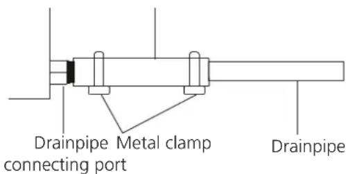
text_image
Drainpipe Metal clamp connecting port Drainpipe
text_image
1-1.5m (39-59') Downward slope 1/100NOTE ON DRAINPIPE INSTALLATION
- When using an extended drainpipe, tighten the indoor connection with an additional protection tube to prevent it from pulling loose.
- The drainpipe should slope downward at a gradient of at least 1/100 to prevent water from flowing back into the air conditioner.
- To prevent the pipe from sagging, space hanging wires every 1-1.5m (39-59").
- If the outlet of the drainpipe is higher than the body's pump joint, provide a lift pipe for the exhaust outlet of the indoor unit. The lift pipe must be installed no higher than 75cm (29.5") from the ceiling board and the distance between the unit and the lift pipe must be less than 30cm (11.8") (depending on models). Incorrect installation could cause water to flow back into the unit and flood.
- To prevent air bubbles, keep the drain hose level or slightly tiled up (<75mm / 3") (some models).

text_image
1 - 1.5m (39-59") ≤30cm (11.8") ≤53cm(20.8") 22cm(8.6") ≤75cm (29.5") 0 - 75mm (3"
text_image
0-53cm (20.8") ≥10cm (4")Pass the drain hose through the wall hole. Make sure the water drains to a safe location where it will not cause water damage or a slipping hazard.
NOTICE
The drainpipe outlet should be at least 5cm (1.9") above the ground. If it touches the ground, the unit may become blocked and malfunction. If you discharge the water directly into a sewer, make sure that the drain has a U or S pipe to catch odors that might otherwise come back into the house.
Drill wall hole
-
Using a 65mm(2.5in) or 90mm(3.54in) (depending on models) core drill, drill a hole in the wall. Make sure that the hole is drilled at a slight downward angle, so that the outdoor end of the hole is lower than the indoor end by about 5mm to 7mm (0.2-0.275in). This will ensure proper water drainage.
-
Place the protective wall cuff in the hole. This protects the edges of the hole and will help seal it when you finish the installation process.
CAUTION
When drilling the wall hole, make sure to avoid wires, plumbing, and other sensitive components.

text_image
Wall Indoor Outdoor mm7-5 h1572.0-2.0NOTE: When the gas side connective pipe is 16mm(5/8in) or more, the wall hole should be 90mm(3.54in).
Refrigerant Piping Connection
When connecting refrigerant piping, do not let substances or gases other than the specified refrigerant enter the unit. The presence of other gases or substances will lower the unit's capacity, and can cause abnormally high pressure in the refrigeration cycle. This can cause explosion and injury.
NOTE ON PIPE LENGTH
Ensure that the length of the refrigerant pipe, the number of bends, and the drop height between the indoor and outdoor units meets the requirements shown in the following table:
THE MAXIMUM LENGTH AND DROP HEIGHT BASED ON MODELS (UNIT: m/ft)
| Type of model | Capacity (Btu/h) Length of piping Maximum drop height | ||
| North America, Australia and the EU Inverter SplitType | <15K 25/82 | 10/32.8 | |
| ≥15K - <24K 30/98.4 | 20/65.6 | ||
| ≥24K - <36K 50/164 | 25/82 | ||
| ≥36K - ≤60K 75/246 | 30/98.4 | ||
| Other Split Type | 12K 15/49 | 8/26 | |
| 18K-24K | 25/82 | 15/49 | |
| 30K-36K | 30/98.4 | 20/65.6 | |
| 42K-60K | 50/164 | 30/98.4 | |

CAUTION
Oil Traps
If oil flow back into the outdoor unit's compressor, this might cause liquid compression or deterioration of oil return.
Oil traps in the rising gas piping can prevent this.
An oil trap should be installed every 6m(20ft) of vertical suction line riser (<36000Btu/h unit).
An oil trap should be installed every 10m(32.8ft) of vertical suction line riser ( ≥ 36000Btu/h unit).
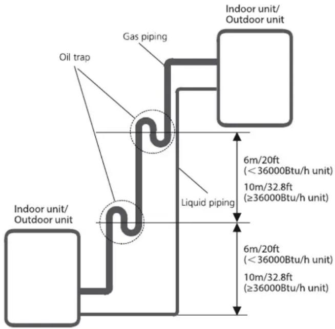
text_image
Oil trap Gas piping Indoor unit/ Outdoor unit 6m/20ft (<36000Btu/h unit) 10m/32.8ft (≥36000Btu/h unit) Liquid piping 6m/20ft (<36000Btu/h unit) 10m/32.8ft (≥36000Btu/h unit)CONNECTION INSTRUCTIONS REFRIGERANT PIPING

CAUTION
- The branching pipe must be installed horizontally, AN angle of more than 10^ may cause malfunction
- DO NOT install the connecting pipe until both indoor and outdoor units have been installed
• Insulate both the gas and liquid piping to prevent water leakage
Step 1: Cut pipes
When preparing refrigerant pipes, take extra care to cut and flare them properly. This will ensure efficient operation and minimize the need for future maintenance.
- Measure the distance between the indoor and outdoor units.
- Using a pipe cutter, cut the pipe a little longer than the measured distance.
- Make sure that the pipe is cut at a perfect 90^ angle.
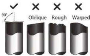
text_image
90° Oblique Rough Warped
DO NOT DEFORM PIPE WHILE CUTTING
Be extra careful not to damage, dent, or deform the pipe while cutting. This will drastically reduce the heating efficiency of the unit.
Step 2: Remove burrs
Burrs can affect the air-tight seal of refrigerant piping connection. They must be completely removed.
-
Hold the pipe at a downward angle to prevent burrs from falling into the pipe.
-
Using a reamer or deburring tool, remove all burrs from the cut section of the pipe.

text_image
Point down Pipe ReamerStep 3: Flare pipe ends
Proper flaring is essential to achieve an airtight seal
- After rmoving burrs from cut pipe, seal the ends with PVC tape to prevent foreign materials from entering the pipe.
- Sheath the pipe with insulation material.
- Place flare nuts on both ends of pipe. Make sure they are facing in the right direction, because you can't put them on or change their direction after flaring.

text_image
Flare nut Copper pipe-
Remove PVC tape from ends of pipe when ready to perform flaring worl.
-
Clamp flare form on the end of the pipe. The end of the pipe must extend beyond the flare form.
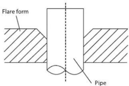
text_image
Flare form Pipe- Place flaring tool onto the form.
- Turn the handle of the flaring tool clockwise until the pipe is fully flared. Flare the pipe in accordance with the dimensions.
PIPING EXTENSION BEYOND FLARE FORM
| Pipe gauge | Tightening Torque | Flare dimension (A) (UnitL mm/inch) Min. Max. | Flare Shape | |
| Φ6.35(Φ1/4") | 18-20 N.m(180-200kgf.cm) | 8.4/0.33 | 8.7/0.34 | 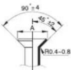 |
| Φ9.52(Φ3/8") | 32-39 N.m(320-390kgf.cm) | 13.2/0.52 | 13.5/0.53 | |
| Φ12.7(Φ1/2") | 49-59 N.m(490-590kgf.cm) | 16.2/0.64 | 16.5/0.65 | |
| Φ16(Φ5/8") | 57-71 N.m(570-710kgf.cm) | 19.2/0.76 | 19.7/0.78 | |
| Φ19(Φ3/4") | 67-101 N.m(670-1010kgf.cm) | 23.2/0.91 | 23.7/0.93 | |
| Φ22(Φ7/8") | 85-110 N.m(850-1100kgf.cm) | 26.4/1.04 | 26.9/1.06 | |
- Remove the flaring tool an flare form, then inspect the end of the pipe for cracks and even flaring.
Step 4: Connect pipes
Connect the copper pipes to the indoor unit first, then connect it to the outdoor unit. You should first connect the low-pressure pipe, then the high-pressure pipe.
-
When connecting the flare nuts, apply a thin coat of refrigeration oil to the flared ends of the pipes.
-
Align the center of the two pipes that you will connect.

text_image
Indoor unit tubing Flare nut Pipe-
Tighten the flare nut as tightly as possible by hand.
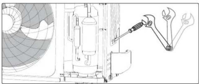
-
Using a spanner, grip the nut on the unit tubing.
-
While firmly gripping the nutm use a torque wrench to tighten the flare nut according to the torque values in above table.
NOTE: Use both a spanner and a torque wrench when connecting or disconnecting pipes to/from the unit.
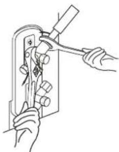
natural_image
Line drawing of hands using a tool to adjust or install a component, no text or symbols present
CAUTION
- Ensure to wrap insulation around the piping. Direct contact with the bare piping may result in burns or frostbite. - Make sure the pipe is properly connected. Over tightening may damage the bell mouth and under tightening may lead to leakage.
NOTE ON MINIMUM BEND RADIUS
Carefully bend the tubing in the middle according to the diagram below. DO NOT bend the ybing more than 90^ or more than 3 times.
Bend the pipe with thumb

natural_image
Line drawing of two hands holding a circular object (no text or symbols)min-radius 10cm (3.9")
- After connecting the copper pipes to the indoor unit, wrap the power cable, signal cable and the piping together with binding tape.
NOTE: DO NOT intertwine signal cable with other wires. While bundling these items togetherm do not intertwine or cross the signal cable with any other wiring
-
Thread this pipeline through the wall and connect it to the outdoor unit.
-
Insulate all the piping, including the valves of the outdoor unit.
-
Fix the water receiver (supplied in Accessories box) to the indoor unit by a screw.
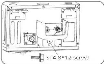
text_image
ST4.8*12 screwNOTICE Two ST4.8*12 screws are supplied, one of which is spare.
- Open the stop valves of the outdoor unit to start the flow of the refrigerant between the indoor and outdoor unit.

CAUTION
Check to make sure there is no refrigerant leak after completing the installation work. If there is a refrigerant leak, ventilate the area immediately and evacuate the system (Refer to the Air Evacuation section of this manual.

BEFORE PERFORMING ANY ELECTRICAL WORK, READ THESE REGULATIONS
- All wiring must comply with local and national electrical codes, regulations and must be installed by a licensed electrician.
- All electrical connections must be made according to the Electrical Connection Diagram located on the panels of the indoor and outdoor units.
- If there is a serious safety issue with the power supply, stop work immediately. Explain your reasoning to the client, and refuse to install the unit until the safety issue is properly resolved.
- Power voltage should be within 90-110% of rated voltage. Insufficient power supply can cause malfunction, electrical shock, or fire.
- If connecting power to fixed wiring, a surgeprotector and main power switch should be installed.
- If connecting power to fixed wiring, a switch or circuit breaker that disconnects all poles and has a contact separation of at least 1/8in (3mm) must be incorporated in the fixed wiring. The qualified technician must use an approved circuit breaker or switch.
- Only connect the unit to an individual branch circuit outlet. Do not connect another appliance to that outlet.
- Make sure to properly ground the air conditioner.
- Every wire must be firmly connected. Loose wiring can cause the terminal to overheat, resulting in product malfunction and possible fire.
- Do not let wires touch or rest against refrigerant tubing, the compressor, or any moving parts within the unit.
- If the unit has an auxiliary electric heater, it must be installed at least 1 meter (40in) away from any combustible materials.
- To avoid getting an electric shock, never touch the electrical components soon after the power supply has been turned off. After turning off the power, always wait 10 minutes or more before you touch the electrical components.
- Make sure that you do not cross your electrical wiring with your signal wiring. This may cause distortion and interference.
- The unit must be connected to the main outlet Normally, the power supply must have an impedance of 32 ohms.
- No other equipment should be connected to the same power circuit.
- Connect the outdoor wires before connecting the indoor wires.

WARNING
BEFORE PERFORMING ANY ELECTRICAL OR WIRING WORK, TURN OFF THE MAIN POWER TO THE SYSTEM.
NOTE ON AIR SWITCH
When the maximum current of the air conditioner is more than 16A, an air switch or leakage protection switch with protective device shall be used (purchased separately). When the maximum current of the air conditioner is less than 16A, the power cord of air conditioner shall be equipped with plug (purchased separately). In North America, the appliance should be wired according to NEC and CEC requirements.

flowchart
graph TD
    A["Air switch (purchased separately)"] --> B["Outdoor unit power wires"]
    B --> C["Outdoor unit"]
    C --> D["Indoor unit"]
    D --> E["Indoor & Outdoor connective wires (purchased separately)"]
    E --> D
NOTE: The cographs are for explanation purpose only. Your macahine may be slightly different. The actual shape shall prevail.
(B)

flowchart
graph TD
    A["Indoor unit"] --> B["Outdoor unit"]
    B --> C["Indoor unit power wires"]
    C --> D["Air switch (Some indoor unit come with their own)"]
    D --> E["Indoor unit"]
    E --> F["Indoor & Outdoor connective wires (purchased separately)"]
(C)

flowchart
graph TD
    A["Indoor unit"] -->|purchased separately| B["Outdoor unit"]
    A -->|purchased separately| C["Indoor & Outdoor connective wires (purchased separately)"]
    D["Air switch"] -->|Some indoor unit come with their own| E["Indoor unit"]
    F["Outdoor unit power wires"] --> A
    G["Outdoor unit power wires"] --> A
(D) (Only for the North American)
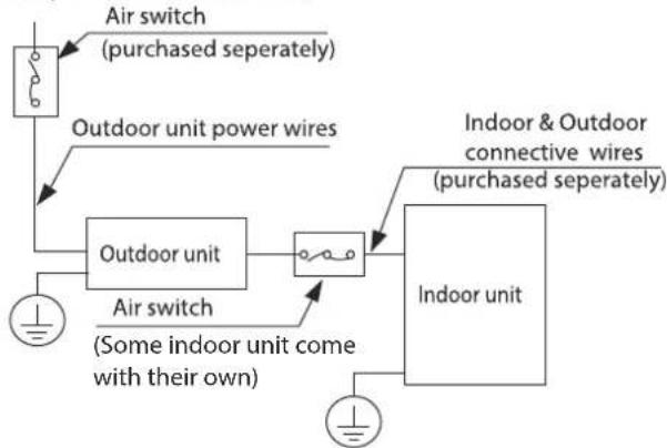
flowchart
graph TD
    A["Air switch (purchased separately)"] --> B["Outdoor unit power wires"]
    B --> C["Outdoor unit"]
    C --> D["Indoor unit"]
    D --> E["Indoor & Outdoor connective wires (purchased separately)"]
    C --> F["Air switch (Some indoor unit come with their own)"]
    F --> G["Ground"]
Outdoor Unit Wiring

WARNING
Before performing any electrical or wiring work, turn off the main power to the system.
- Prepare the cable for connection
A. You must first choose the right cable size. Be sure to use H07RN-F cables.
NOTE: In North America, choose the cable type according to the local electrical codes and regulations.
Minimum Cross-Sectional Area of Power and Signal Cables (for reference)
| Rated Current of Appliance (A) | Nominal Cross-Sectional Area (mm2) |
| >3 and ≤6 | 0.75 |
| >6 and ≤10 | 1 |
| >10 and ≤16 | 1.5 |
| >16 and ≤25 | 2.5 |
| >25 and ≤32 | 4 |
| >32 and ≤40 | 6 |
CHOOSE THE RIGHT CABLE SIZE
The size of the power supply cable, signal cable, fuse, and switch needed is determined by the maximum current is indicated on the nameplate located on the side panel of the unitl Refer to this nameplate to choose the right cable, fuse, or switch.
NOTE: In North America, please choose the right cable size according to the Minimum Circuit Ampacity indicated on the nameplate of the unit.
B. Using wire strippers, strip the rubber jacket from both ends of the signal cable to reveal approximately 15cm (5.9") of wire.
C. Strip the insulation from the ends.
D. Using a wire crimper, crimp u-lugs on the ends.
NOTE: When connecting the wires, strictly follow the wiring diagram found inside the electrical box cover.
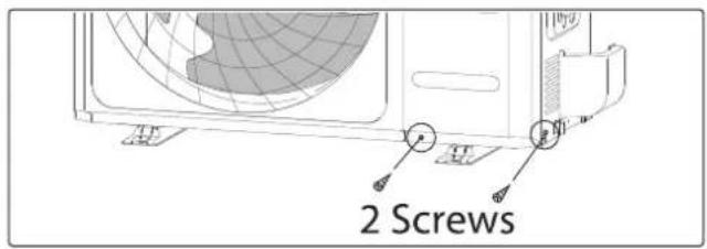
- Remove the 2 screws fixed on the front panel and side panel, then take it down to perform wire connection (see the figure of outdoor unit A). Unscrew the electrical wiring cover and remove it. (see the figure of outdoor unit B)
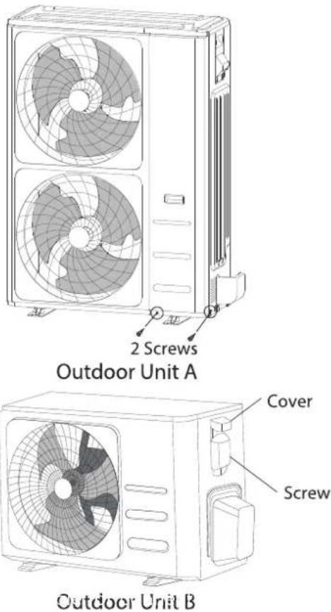
text_image
2 Screws Outdoor Unit A Cover Screw Outdoor Unit B-
Connect the u-lugs to the terminals. Match the wire colors/labels with the labels on the terminal block. Firmly screw the u-lug of each wire to its corresponding terminal.
-
Clamp down the cable with the cable clamp.
-
Insulate unused wires with electrical tape. Keep them away from any electrical or metal parts.
-
Reinstall the cover of the electric control box.
Australia Models
Please prepare spanner and flat-blade screw-driver before your installation work.
- Remove two fixing screws, then remove the front panel.
text_image
2 Screws- Use spanner and flat-blade screwdriver to knock down two metal seals, the pick the metal flakes out.
natural_image
Technical line drawing of a mechanical assembly with tools and components (no text or symbols)-
Connect the power cable and indoor & outdoor connection cable. Clamp down the cable with the cable clamp.
-
The wire groups shall be bound with cable ties and fixed on the right side plate after they are connected. The strong electric wire group and weak electric wire shoup shall be led out separately through the two knock down holes on the bottom of the right side plate and fastened with a locking connector as shown in the figure below.

text_image
Technical diagram of an air conditioning unit with fan blades and internal components, annotated with Chinese annotations.Outdoor Unit Wiring
- Prepare the cable for connection
A. Using wire strippers, strip the rubber jacket from both ends of the signal cable to reveal about 15cm(5.9") of the wire.
B. Strip the insulation from the ends of the wires.
C. Using a wire crimper, crimp the u-lugs to the ends of the wires.
-
Remove the cover of the electric control box on your indoor unit.
-
Connect the u-lugs to the terminals. Match the wire colors/labels with the labels on the terminal block. Firmly screw the u-lug of each wire to its corresponding terminal. Refer to the Serial Number and Wiring Diagram located on the cover of the electric control box.
CAUTION
- While connecting the wires, please strictly follow the wiring diagram.
- The refrigerant circuit can become very hot. Keep the interconnection cable away from the copper tube.
-
Clamp down the cable with the cable clamp. The cable must not be loose or pull on the u-lugs.
-
Reattach the electric box cover.
Air Evacuation
Outdoor Unit Wiring
Air and foreign matter in the refrigerant circuit can cause abnormal rises in pressure, which can damage the air conditioner, reduce its efficiency, and cause injury. Use vacuum pump and manifold gauge to evacuate the refrigerant circuit, removing any non-condensable gas and moisture from the system. Evacuation should be performed upon initial installation and when unit is relocated.
BEFORE PERFORMING EVACUATION
√ Check to make sure the connective pipes between the indoor and outdoor units are connected properly.
√ Check to make sure all wiring is connected properly.
Evacuation Instructions
- Connect the charge hose of the manifold gauge to service port on the outdoor unit's low pressure valve.
- Connect another charge hose from the manifold gauge to the vacuum pump.
- Open the Low Pressure side of the manifold gauge. Keep the High Pressure side closed.
- Turn on the vacuum pump to evacuate the system.
- Run the vacuum for at least 15 minutes, or until the Compound Meter reads -76cmH-G(-10 ^5 Pa)

text_image
Manifold Gauge Compound gauge -76cmHg Pressure gauge High pressure valve Pressure hose / Charge hose Charge hose Vacuum pump Low pressure valve Low pressure valve- Close the Low Pressure side of the manifold gauge, and turn off the vacuum pump.
- Wait for 5 minutes, then check that there has been no change in system pressure.
- If there is a change in system pressure, refer to Gas Leak Check section for information on how to check for leaks. If there is no change in system pressure, unscrew the cap from the packe valve (high pressure valve).
- Insert hexagonal wrench into the packed valve (high pressure valve) and open the valve by turning the wrench in a 1/4 counterclockwise turn. Listen for gas to exit the system, then close the valve after 5 seconds.
- Watch the Pressure Gauge for one minute to make sure that there is no change in pressure. The Pressure Gauge should read slightly higher than atmospheric pressure.
- Remove the charge hose from the service port.
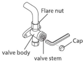
text_image
Flare nut valve body valve stem Cap- Using hexagonal wrench fully open both the high pressure and low pressure valves.
- Tighten valve caps on all three valves (servive port, high pressure, low pressure) by hand. You may tighten it further using a torque wrench if needed.
! OPEN VALVE STEMS GENTLY
When opening valve stems, turn the hexagonal wrench until it hits against the stopper.
Do not try to force the valve to open further.
NOTE ON ADDING REFRIGERANT
Some systems require additional charging depending on pipe lengths. The standard pipe length varies according to local regulations. For example, in North America, the standard pipe length is 7.5m (25'). The refrigerant should be charged from the service port on the outdoor unit's low pressure valve. The additional refrigerant to be charged can be calculated using the following formula:
Liquid Side Diameter
| Refrigerant | 6.35(1/4") | 9.52(3/8") | 12.7(1/2") |
| R401A:(orifice tube in the indoor unit): | (Total pipe length-standard pipe length) x30g(0.32oz)/m(ft) | (Total pipe length-standard pipe length) x65g(0.69oz)/m(ft) | (Total pipe length-standard pipe length) x115g(1.23oz)/m(ft) |
| R401A:(orifice tube in the outdoor unit): | (Total pipe length-standard pipe length) x15g(0.16oz)/m(ft) | (Total pipe length-standard pipe length) x30g(0.32oz)/m(ft) | (Total pipe length-standard pipe length) x65g(0.69oz)/m(ft) |

CAUTION: DOT NOT MIX REFRIGERANT TYPES
Electrical and Gas Leak Checks
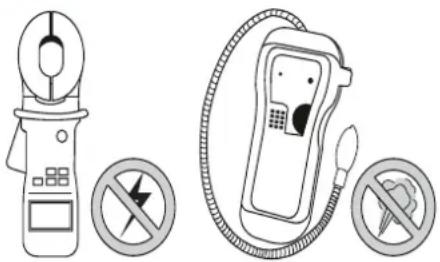
text_image
Safety warning symbols for a fuel pump and its prohibition signs, indicating no protection or no leakage.
WARNING - RISK OF ELECTRICAL SHOCK
ALL WIRING MUST BE INSTALLED BY A LICENSED ELECTRICIAN AND COMPLY WITH LOCAL, STATE, AND NATIONAL ELECTRICAL CODES.
Electrical Safety Checks
After installation is complete, confirm that all electrical wiring has been installed in accordance with local and national regulations, and according to the installation manual.
BEFORE TEST RUN
Check Grounding Work Measure grounding resistance by visual detection and with a grounding resistance tester. Grounding resistance must be less than 0.1Ω.
NOTE: This may not be required for some locations in North America.
DURING TEST RUN
Check for Electrical Leakage During the Test Run, use an electroprobe and multimeter to perform a comprehensive electrical leakage test.
IF ELECTRICAL LEAKAGE IS DETECTED
If electrical leakage is detected, turn off the unit immediately and call a licensed electrician to find and resolve the cause of the leakage.
NOTE: This may not be required for some locations in North America.
Gas Leak Checks
There are two different methods to check for gaseous leaks. Use Fig. 8.1 below as a guide for the critical points to check for leaks.
Soap and Water Method Using a soft brush or spray bottle, apply a soapy water solution to all of the pipe connection points of the indoor and outdoor units, watching to see if any bubbles form. The presence of bubbles indicates there is a leak.
Leak Detector Method If using a leak detector, refer to the device's operation/instruction manual for proper usage instructions.
AFTER PERFORMING GAS LEAK CHECKS
After confirming that all of the refrigerant pipe connections points DO NOT leak, replace the valve cover on the outside unit and wrap and insulate the piping connections of the indoor unit.
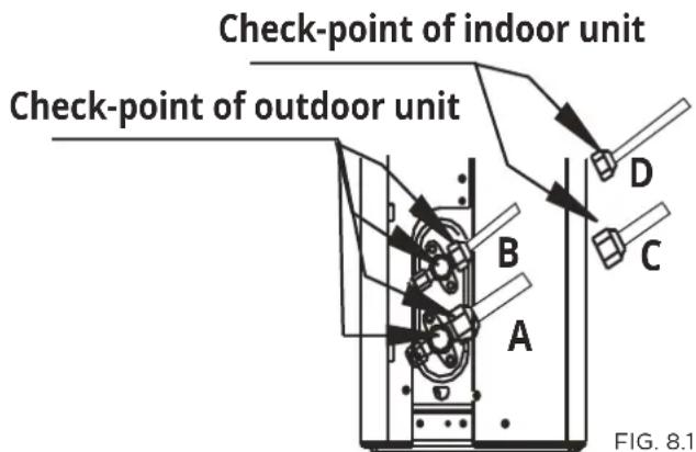
text_image
Check-point of indoor unit Check-point of outdoor unit A B C D FIG. 8.1A: Low pressure stop valve
B: High pressure stop valve
C & D: Indoor unit flare nuts
Panel Installation
Step 1 Prepare and Install Ceiling
- Drill 430 mm x 1300 mm(16.93"x51.18") hole into the ceiling based on the layout of the installation board. The centre of the ceiling opening should match the centre of the body of the indoor unit.
NOTICE
In order to keep the ceiling level and prevent vibrations, reinforce the strength of the ceiling when necessary.
- Once the ceiling is cut, remove the installation board.
- Then install the ceiling.
Step 2 Panel Installation
Model A
NOTICE
- The air grille received by the customer is not tightened by the wire rope, but is specially designed to be loose for easy installation.
- Grab air grille with your fingers and pull it out slowly in the direction of the arrow.

natural_image
Diagram of a rectangular device with internal components and an upward arrow, no visible text or symbolsGrab at these locations

natural_image
Architectural cross-section diagram of a multi-level building or loading unit with internal compartments and structural elements (no text or labels)
- Manually rotate the air deflector, fix the panel to the cassette by using 3×M4*22 screws and a ST3.9*16 screw.
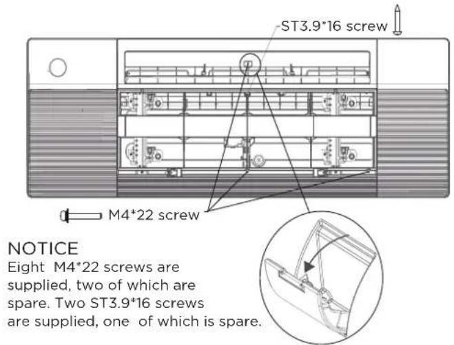
text_image
ST3.9*16 screw M4*22 screw NOTICE Eight M4*22 screws are supplied, two of which are spare. Two ST3.9*16 screws are supplied, one of which is spare.Before fixing this screw, you need to open the screw cover; and after fixing screw, please close the cover.
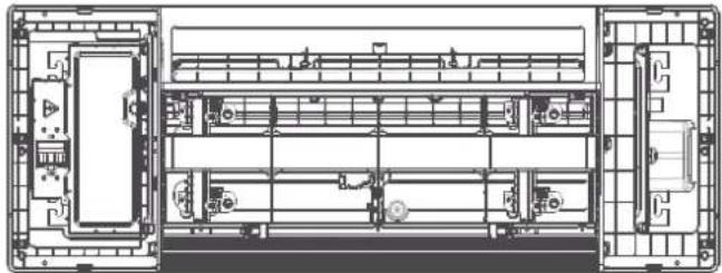
- Open the two covers on both sides of the panel, fix the panel to the cassette by using 3 × M4^*22 screws.

natural_image
Architectural floor plan showing room layouts and structural elements (no text or labels)
- Connect the display board to the main control board, up to four wires are required to connect.
NOTICE
The corresponding colors or corresponding pins are connected each other.
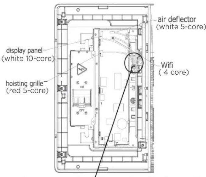
text_image
display panel (white 10-core) hoisting grille (red 5-core) air deflector (white 5-core) Wifi (4 core)when connection is completed, please clip the wires to the buckle.
• Install the control box cover and turn the circuit breaker to ON, then close the two plastic covers on both sides of the panel.
natural_image
Architectural floor plan showing room layouts and structural elements (no text or labels)
natural_image
Architectural floor plan of a multi-level building with visible room layouts and equipment (no text or labels)- During the test-run process, the display will be lighted and the air griller will rise automatically.

natural_image
Line drawing of a modern air conditioner unit with ventilation grilles and a flat top panel (no text or symbols)Model B
- Press the circular positon to open the two screw covers, then remove the two screws.
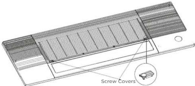
text_image
Screw Covers- Hold and open the air grille, then push both of the latch to the middle to unlock the air grille.
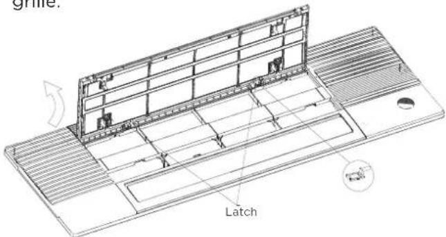
text_image
Latch- Pull the panel grille out of the panel, fix the cassette panel to the one-way casset by two plastic buckles.
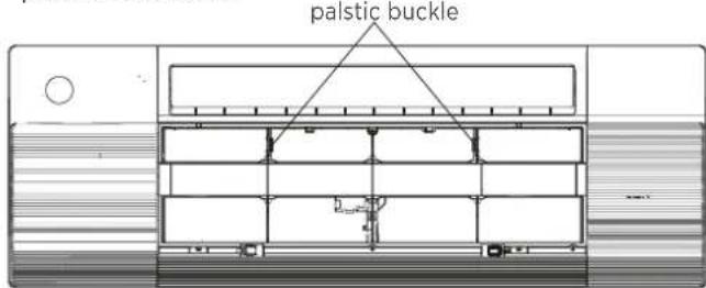
text_image
palstic buckle- Manually rotate the air deflector, fix the panel to the cassette by using 3×M4*22 screws and a ST3.9*16 screw.

text_image
screws and a ST3.9*16 screw. ST3.9*16 screw M4*22 screw NOTICE Eight M4*22 screws are supplied, two of which are spare. Two ST3.9*16 screws are supplied, one of which is spare.Before fixing this screw, you need to open the screw cover; and after fixing screw, please close the cover.
- Open the two covers on both sides of the panel, fix the panel to the cassette by using3× M4*22 screws.

text_image
M4*22 screw- Connect the display board to the main control board, up to four wires are required to connect.
NOTICE
The corresponding colors or corresponding pins are connected each other.
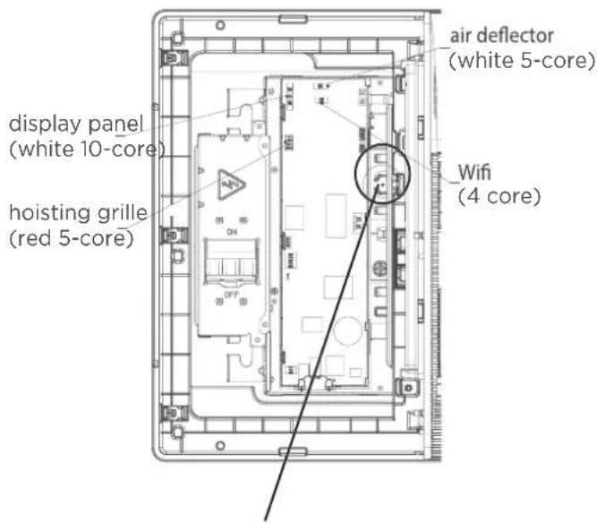
text_image
display panel (white 10-core) hoisting grille (red 5-core) air deflector (white 5-core) Wifi (4 core)when connection is completed, please clip the wires to the buckle.
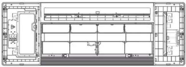
• Install the control box cover and turn the circuit breaker to ON, then close the two plastic covers on both sides of the panel.
natural_image
Architectural floor plan showing room layouts and structural elements (no text or labels)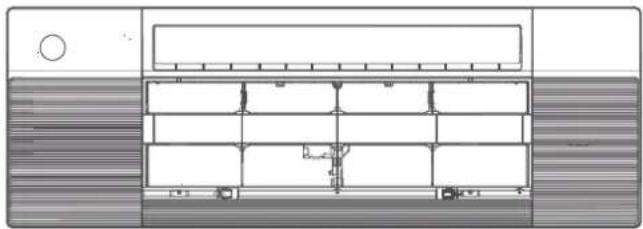
natural_image
Architectural floor plan showing room layouts and structural elements (no text or labels)- Re-install the air grille by pushing the latch to lock it and fixing the two screws, then close the two screw covers.
natural_image
Line drawing of a modern air conditioner unit with ventilation grilles and a handle (no text or symbols)Step 3 Optional Parts Installation
Wireless module
Wireless module, or named smart kit, if you choose this configuration, please follow the steps below to install.
NOTICE
If you choose this configuration, it is recommended that installing this wireless module during the step of panel installation.
- Remove the protective cap of the wireless module (smart kit).

natural_image
Line drawing of a mechanical component with an arrow indicating direction (no text or symbols)- Open the cover with display panel, loosen the screw and remove the cover.
natural_image
Diagram of a server rack with ventilation grilles and a downward arrow indicating process (no text or symbols)Loosen the screw and remove the cover

natural_image
Technical line drawing of an open electronic device chassis with internal components (no text or symbols)- Open the front panel and insert the wireless module (smart kit) into the reserved interface.

text_image
5 core infrared controller plug
WARNING
This interface is only compatible with wireless module (smart kit) provided by the manufacturer.
For the function introduction and operation instruction, please refer to the user manual of smart kit.
Test Run
Before Test Run
A test run must be performed after the entire system has been completely installed. Confirm the following points before performing the test:
a. Indoor and outdoor units are properly installed.
b. Piping and wiring are properly connected.
c. No obstacles near the inlet and outlet of the unit that might cause poor performance or product malfunction.
d. Refrigeration system does not leak.
e. Drainage system is unimpeded and draining to a safe location.
f. Heating insulation is properly installed.
g. Grounding wires are properly connected.
h. Length of the piping and additional refrigerant stow capacity have been recorded.
i. Power voltage is the correct voltage for the air conditioner.

CAUTION
Failure to perform the test run may result in unit damage, property damage, or personal injury.
Test Run Instructions
- Open both the liquid and gas stop valves.
- Turn on the main power switch and allow the unit to warm up.
-
Set the air conditioner to COOL mode.
-
For the Indoor Unit
A. Double check to see if the room temperature is being registered correctly.
B. Ensure the manual buttons on the indoor unit works properly.
C. Check to see that the drainage system is unimpeded and draining smoothly.
D. Ensure there is no vibration or abnormal noise during operation.
- For the Outdoor Unit
A. Check to see if the refrigeration system is leaking.
B. Make sure there is no vibration or abnormal noise during operation.
C. Ensure the wind, noise, and water generated by the unit do not disturb your neighbors or pose a safety hazard.
NOTE: If the unit malfunctions or does not operate according to your expectations, please refer to the Troubleshooting section of the Owner's Manual before calling customer service.
Water Discharge Test
- Before the test, make sure that the water discharge pipeline is smooth, and check that each connection is sealed properly.
-
Conduct the water discharge test in the new room before the ceiling is paved.
-
Connect the power supply, and set the air conditioner to operate in the cool mode. Check the running sound of the drainage pump.
- Keep cool mode running at least 10 min.
- Stop the air conditioner. Wait for three minutes, and then check if there is anything unusual. If the water discharge iping layout is not correct, the excessive water flow will cause the water level error and "EE" error code will be displayed on the display panel. There may even be water overflowing from the water pan.
- Continue to add water until the alarm for excessive water levels is triggered. Check if the drainage pump drains water immediately. After three minutes, if the water level does not fall below the warning level, the unit will shut down. At this time, you need to turn off the power supply, and drain away the accumulated water before you can turn on the unit normally.
- Turn off the power supply, remove the water manually using the drainage plug, and put the test cap back to the original place.
CAUTION
The drainage plug at the bottom of the unit body is used to discharge accumulated water from the drain pan when the air conditioner malfunctions. When the air conditioner is operating normally, make sure the drainage plug is properly plugged to prevent water from leaking.

CAUTION
The power supply must comply with the rating label.
Wiring Figure
Indoor & Outdoor connection:

flowchart
graph TD
    A["Indoor Unit Terminals"] --> B["Connect to Outdoor Unit"]
    B --> C["Ground"]
    C --> D["Connecting cable outdoor unit to indoor unit (36AWG)"]
    D --> E["Field Power Supply"]
    E --> F["Indoor Unit Terminals"]
    F --> G["Connect to Indoor Unit"]
    G --> H["Main Power Supply 20B-250V-1-60Hz"]
    H --> I["Field Power Supply"]

CAUTION
The wiring must be operated according to the wiring scheme, or it damages the unit. Before obtaining access to terminals, all supply circuits must be disconnected.