UC Mini - Seva Teo - Free user manual and instructions
Find the device manual for free UC Mini Teo in PDF.

User questions about UC Mini Teo
0 question about this device. Answer the ones you know or ask your own.
Ask a new question about this device
Download the instructions for your Seva in PDF format for free! Find your manual UC Mini - Teo and take your electronic device back in hand. On this page are published all the documents necessary for the use of your device. UC Mini by Teo.
USER MANUAL UC Mini Teo
Installation Instructions

natural_image
Front view of a black TEO UC Mini server rack with ventilation grilles and control buttons (no readable text beyond branding)Teo UC Mini Server Installation Instructions
© 2014 Teo Technologies, Inc. All rights reserved.
Contents
Introduction....5
Using this Manual....5
Front Panel....6
Back Panel....7
Installation....9
Installation Overview....9
Safety Guidelines and General Installation....10
Wall Mounting 12
Power 13
Ethernet Network Connection....14
Telephony Connections....15
Configuration and Administration 21
Joining the Local Domain 21
Configuring System Options 21
User Configuration Options....23
Specifications 25
Service and Warranty....27
Service....27
Teo Product Warranty 27
Safety and Regulatory Requirements....29
Cautions 29
FCC Part 15....29
National Electrical Code 29
Teo UC Mini Server Installation Instructions
Introduction
The Teo UC (Unified Communications) System is a SIP-based VoIP platform that integrates a wide variety of communications services via a software-based solution that runs on the UC Mini Server or the larger-capacity UC Pro Server. The servers run proprietary Teo software on a Linux operating system, and can be configured for a wide range of station and call capacities.
Features of the UC System include:
- Automated Attendant
- Voicemail
- Conferencing
- Call reporting
- Call recording
- Mobile phone support
- Softphone
• Presence-based call routing - Fax Server
• E911
• LDAP/Active Directory integration
• Mass provisioning of users
• Mass provisioning of devices
• Centralized administration of all system functions
Using this Manual
This manual covers the hardware installation and initial configuration of the UC Mini Server.
- Connectors, switches, and indicators on the front and back panels are described in this chapter.
- The Installation chapter covers wall mounting, power, and trunk and device connections.
- The Configuration and Administration chapter gives a brief introduction to the web-based Administration and User Portals. Detailed online help for these tools can be accessed from the portal interfaces.
Front Panel
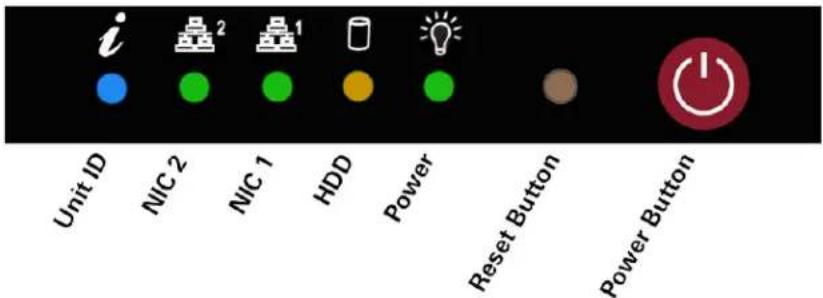
Power and drive indicators are located on the UC Mini Server front panel. The power switch and reset button are also located here.
text_image
i Unit ID NIC 2 NIC 1 HDD Power Reset Button Power Button
NIC 1 – flashing indicates network activity on Ethernet interface 1.

HDD – flashing indicates drive activity.

Power – indicates that power is being supplied to the system's power supply unit. This indicator should normally be illuminated when the system is operating.

Reset Button – press in with a pen or other small tool to force a reboot of the system.

Power Button – used to apply or remove power from the power supply to the server system. Turning off system power with this button removes the main power but keeps standby power supplied to the system. Therefore, you must unplug the system power cord before servicing.
These indicators are typically active only during troubleshooting:

Unit ID – controlled by IPMI. Flashes to identify the selected server.

NIC 2 – flashing indicates network activity on Ethernet interface 2.
Back Panel
The back panel has the power switch, and connectors for:
- Power supply
- Ethernet port (NIC1)
- PRI telephony port
• Analog telephony ports - Other computer connectors (typically used for troubleshooting only):
○ USB
- Ethernet port (NIC 2)
- IPMI LAN port
- VGA video
- RS232 serial port
Telephony Ports

text_image
Power IPMI LAN RS232 Serial USB (4) NIC 1 NIC 2 VGA VideoTeo UC Mini Server Installation Instructions
Installation
Installation Overview
The UC Mini Server is shipped with all ordered options installed at the factory.
You will need to perform the following steps to install the UC Mini Server:
- Mount the UC Mini Server in a 19" rack.
- Connect AC power.
- Connect the UC Mini Server to the LAN.
- Connect optional Telco ISDN-PRI trunks to the UC Mini Server.
- Connect optional analog trunks and analog station devices to the UC Mini Server.
- Configure the UC Mini Server to join the network domain.
Safety Guidelines and General Installation
Safety Guidelines
Prior to installing the system, read and follow all safety guidelines. The UC Mini Server must be installed only by qualified personnel. The following warnings and cautions must be observed during installation and operation of the system.
WARNING!
RISK OF ELECTRICAL SHOCK!
Never install telephone wiring during a lightning storm.
Never install telephone jacks in wet locations unless the jack is specifically designed for wet locations.
Never touch uninsulated telephone wires or terminals unless the telephone line has been disconnected at the network interface.
Do NOT attach or staple the AC power cord to any building surface.
No user-serviceable parts inside; do NOT open the case.
CAUTION!
To reduce the risk of fire, use only No. 26 AWG UL Listed or CSA Certified Telecommunications Line Cord for all connections to the telephone network.
CAUTION!
This equipment shall be installed only in restricted access areas in accordance with Articles 110-16, 110-17 and 110-18 of the National Electrical Code ANSI/NFPA No. 70–1987 and any local codes as required.
Installation
Unpack and Inspect the Equipment
Check the components for damage that might have occurred during shipment. If any equipment is damaged, contact the carrier. Verify that the shipment is complete by comparing the shipped equipment with the shipping list.
The following items are included:
(1) UC Mini Server
(1) Power cord
4-position to 6-position crossover cords or line splitter cords if required by the installed analog ports
Mounting screws
(1) Installation Instructions (this manual)
Location Requirements
The UC Mini Server installation requires a clean, secure room on the customer premises. The room must have adequate ventilation and room for front and rear panel access. The UC Mini Server must be installed per articles 115-15, 110-17 and 110-18 of the National Electrical Code ANSI/MFPA.
The UC Mini Server must be rack mounted.
Environmental Considerations
The UC Mini Server is designed to operate within the following environmental limits:
Operating Temperature: 50° to 85° F / 10° to 35° C (outside the chassis)
Operating Humidity: 8 to 90% (non-condensing)
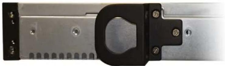
Rack Mounting
The UC Mini Server comes with two rack mounting brackets, which are located on each side at the front of the chassis. To mount the system into a rack, simply screw these brackets directly to the front of the rack (two supplied screws for each bracket).
The brackets can be located at the front of the chassis or moved approximately one-third to the rear of the chassis.

natural_image
Close-up of a metallic mechanical component with mounting holes and a black handle (no visible text or symbols)Default Front Position
natural_image
Close-up of a metallic mechanical component with a black clip and mounting holes (no visible text or symbols)Alternate ^1/_3 Back Position
Power
The UC Mini Server is equipped with a built-in power supply.

natural_image
Close-up of a computer power connector showing fan and socket components with an arrow pointing to a terminal block (no text or symbols visible)Power Connector
- Connect the power connector on the back panel to a standard 120 VAC, 60 Hz power outlet using the supplied IEC power cord.
To turn the UC Mini Server off when it is running, briefly press the power switch on the front panel for an orderly shutdown. The server should always be shut down before power is removed to prevent possible data loss.
To restart UC Mini Server when it is off, briefly press the power switch.
Your system is configured in the computer BIOS to automatically start when power is restored after a temporary loss of power.
Ethernet Network Connection
Use a Category 5 or better network cable when connecting to a 100 Mbps network. Use a Category 5e or better network cable when connecting to a GbE network.

text_image
to LAN- Connect the NIC1 Ethernet port on the UC Mini Server to your LAN. The local SIP telephone devices are on this LAN.
Telephony Connections
The UC Mini Server may be configured at the factory with one of several optional telephony port cards, which can include PRI trunk, analog trunk (FXO), and analog device (FXS) ports. Use the images below to identify the ports on your UC Mini Server.
Telephony ports are on a single card, accessible from the back panel.
Port Identification
Note - The connector orientation may be reversed (rotated 180^ ) on some cards.
PRI Trunk Port
Eight-position connector surrounded by a metal shield – connects to an ISDN Primary Rate Interface (PRI) trunk.
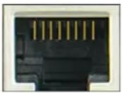
Analog Ports
To determine analog port configuration, apply power to the server before connecting any analog trunks or station devices, this will illuminate the installed ports. The color and size of the connector indicates the port configuration.
Analog Station Device (FXS) Port
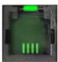

Four- or six-position connector, lit green – connects to one analog station device, such as a telephone or fax machine.
Analog Trunk (FXO) Port, 1 trunk

Four-position connector, lit red – connects to one analog loop start trunk.
Analog Trunk (FXO) Port, 2 trunks
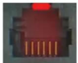
Six-position connector, lit red – connects to two analog loop start trunks.
Teo UC Mini Server Installation Instructions
Card Configurations
Available factory-installed telephony cards are shown in this section. Only one card can be installed in the UC Mini Server.
One, Two, or Four PRI Ports
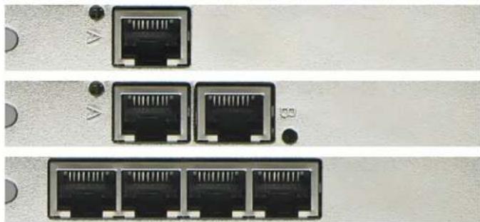
natural_image
Three identical network ports with port labels, shown from top to bottom (no text or symbols on the ports themselves)Four FXS/FXO Ports
This card can be configured with (4) FXS, (4) FXO, or (2) FXS + (2) FXO ports.

natural_image
Four identical black Ethernet ports with green and red indicator lights, arranged in a row on a textured surface (no text or symbols visible)One FXS + Four FXO Ports
Each FXO connector on this card has two ports. Line splitter cords are supplied with this card option.

natural_image
Two black electronic connectors with green and red pins, placed on a textured surface (no text or symbols visible)One PRI + One FXS + Four FXO Ports
This card is similar to the one shown above, with the addition of (1) PRI port.

natural_image
Close-up of three black Ethernet connectors with green and red labels (no text or symbols visible)Installation
Connecting to Telco PRI Trunks
Connection to the external telephone network is typically through one or more ISDN PRI trunks.
Each PRI port can be configured to support up to 23 simultaneous calls.
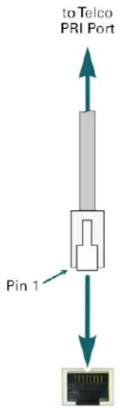
text_image
to Telco PRI Port Pin 1- Connect each PRI port to an ISDN PRI trunk, using standard Ethernet cables.
Note – Some installations may require a PRI swap cable or swap adapter to reverse the transmit and receive pairs.
ISDN PRI Trunk Port Connector Pinout (with Crossover Cable)
| Pin Number | PRI Port | Trunk |
| 1 Transmit Tip Receive Tip | ||
| 2 Transmit Ring Receive Ring | ||
| 3 -- | ||
| 4 Receive Tip Transmit Tip | ||
| 5 Receive Ring Transmit Ring | ||
| 6 -- | ||
| 7 -- | ||
| 8 -- |
Teo UC Mini Server Installation Instructions
Analog Connections
WARNING! RISK OF EQUIPMENT DAMAGE!
The UC Mini Server supplies power on FXS device ports, and receives power from the telephone trunks on FXO trunk ports.
Ensure that the correct UC Mini Server ports are used when connecting analog trunks or station devices.
You will need to refer to the analog port numbers when configuring the system from the UCM Admin Portal. The connector with the lowest numbered port is on the left when facing the back of the UC Mini Server.
Connecting to Analog Trunks
FXO ports connect to standard analog loop start (POTS) telephone trunks.
Your UC Mini Server may have 4-position connectors supporting one trunk, or 6-position connectors supporting two trunks; follow the appropriate instructions below.
4-Position Connectors

text_image
Pin 1 4 6 Pin 1 to Analog Trunk- Use the supplied yellow crossover cord. Connect the 4-position plug to the server, and connect the 6-position plug to the analog trunk jack.
6-Position Connectors

flowchart
graph TD
    A["Port"] --> B["Pin 1"]
    B --> C["6 Pin 1"]
    C --> D["to Analog Trunks"]
    D --> E["Pin 1"]
    E --> F["6 Pin 1"]
    F --> G["to Analog Trunks"]
    G --> H["Pin 1"]
- Use the supplied line splitter cord as shown to connect to two individual 6-position trunk jacks.
The lower numbered trunk port is labeled "Port N" on the cord, and the higher numbered port is labeled "Port N+1".
Installation
Analog Trunk (FXO) Port Connector Pinouts
One Port per Connector
| Server Pin Number(4-Position Plug) | Analog Trunk Pin Number(6-Position Plug) | Signal |
| -- -- | ||
| 1 5 - | ||
| 2 4 Tip | ||
| 3 3 Ring | ||
| 4 2 - | ||
| -- -- |
Two Ports per Connector
| Server Pin Number(6-Position Plug) | Analog Trunk 1 Pin Number(6-Position Plug) | Analog Trunk 2 Pin Number(6-Position Plug) | Signal |
| 1 - | |||
| 2 4 Tip 2 | |||
| 3 4 Tip 1 | |||
| 4 3 | Ring 1 | ||
| 5 3 | Ring 2 | ||
| 6 - |
Teo UC Mini Server Installation Instructions
Connecting to Analog Station Devices
FXS ports connect to analog (POTS) station devices, such as telephones or fax machines. Your UC Mini Server may have 4-position or 6-position connectors; follow the appropriate instructions below.
4-Position Connectors
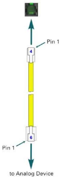
flowchart
graph TD
    A["Device"] -->|Pin 1| B["4 Pin 1"]
    B --> C["6 Pin 1"]
    C --> D["to Analog Device"]
- Use the supplied yellow crossover cord. Connect the 4-position plug to the server, and connect the 6-position plug to the analog device.
6-Position Connectors

text_image
Pin 1 6 6 Pin 1 to Analog Device- Use a standard telephone line cord to connect to the analog device.
Analog Device (FXS) Port Connector Pinout
| Server Pin Number(4-Position Plug) | Server Pin Number(6-Position Plug) | Analog Device Pin Number(6-Position Plug) | Signal |
| - 1 6 - | |||
| 1 2 5 - | |||
| 2 3 4 Tip | |||
| 3 4 3 Ring | |||
| 4 5 2 - | |||
| - 6 1 - |
Configuration and Administration
Joining the Local Domain
The UC Mini Server may be preconfigured at the factory with a network address specified by the customer. If no custom address was requested, the system will be configured with DHCP enabled.
Network addresses can be changed from the System Configuration – Network Resources options in the Administration portal.
Configuring System Options
- All configurable options are set via a web-based remote administration session.
- Open a web browser on any computer that has access to the LAN. A widescreen display of at least 1680 x 1050 resolution is recommended. Adobe Flash Player is required.
- Browse to the address of the UC Mini Server.
- When the login screen appears, log in to the UC Mini Server using the administration username and password that was supplied by Teo (you can change the username and password or add additional administration accounts later).

text_image
TEO Username: My Username Password: ********** ■ Rememberes password: LPGIN +0.1.878 Target Password• The Administration Dashboard will be shown.
Teo UC Mini Server Installation Instructions
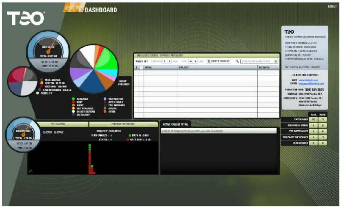
text_image
TEO® DASHBOARD IMPORT MESSAGE CENTER - ENREAD MESSAGES PAGE 1 OF 1 PREVIOUS NEXT POST LAST DELETE CHECKED ERROR FOR NAME DIRECT FROM SUBJECT RECEIVED TEST CUSTODER TEO UNBED COMMUNICATIONS MANAGER SOFTWARE VERSION v-1.1.18 SERIAL NUMBER: 120443001 SPRIP MAC: 00.22-05/00:00:04 LICENSE ID: 13.26.2011 SUPPORT REMINAL DATE: 12.30.2015 EADREQUENCY ALTFING (MANSLED) TED CUSTOMER SUPPORT WEB www.ankred.com EMAIL: newspent@kenter.com PHONE SUPPORT: (806) 524-0024 NORMAL: GM-PSM Pacific, M-F EMBERCENCY: GPS-12MM Pacific, M-F GM-PSM Pacific Web ends & Holidays CPU LADAMS ETHENSIT INTERFACE SERVER IP: 10.10.08.524 VLAN ENABLED: DATA IN: 0.00 D STATUS: DATA SENT: 1.0 VIE ACTIVE CALLS (I TOTAL) (893) 65-81 (5:43:21) (SPA) (Ena3.576) enb 3381 (Ena3.576) TOTAL: 1.79 GB MENEFUS TOTAL: 1.91 GB OUTPUT DATA INPUT DATA SERVICEUse the menus at the top of the screen to access the configuration options.
Online help is available for most configuration options. Click the ? icon to view help in a new browser tab or window.
- When finished with the administration session, click LOGOUT at the upper right of the screen.
User Configuration Options
Each telephone user can configure a limited set of options. The administrator must set up an account name and password for each user.
- The user needs to browse to the login page (UC Mini Server address). A display resolution of 1024 x 768 is sufficient for the User Portal interface. Adobe Flash Player is required.
After logging in, the user can access their call history and configuration options.
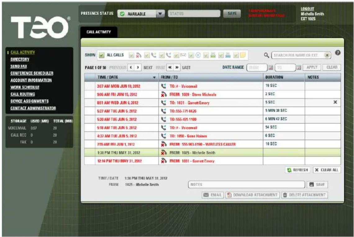
text_image
TEO PRESENT STATUS AVAILABLE STATUS SAVE DOWNLOADS NAME ORDER COPY LOGOUT Michelle Smith EXT 1025 CALL ACTIVITY SHOW ALL CALLS SEARCH FOR NAME OR EXT PAGE 1 OF 50 PREVIOUS < > NEXT FIRST >> LAST DATE RANGE FROM TO APPLY CLEAR TIME / DATE FROM / TO DURATION NOTES 3:07 AM MON JUN 19, 2012 TO: # - Voicemail 19 SEC 9:06 AM FRI JUN 15, 2012 FROM: 1029 - Steve Michaels 2 SEC 8:51 AM WED JUN 5, 2012 TO: 1031 - Garrett Emory 5 SEC 5:27 AM TUE JUN 5, 2012 TO: 555-771-6626 5 MIN 38 SEC 5:20 AM TUE JUN 5, 2012 TO: 555.481.1100 6 MIN 47 SEC 5:18 AM TUE JUN 5, 2012 TO: # - Voicemail 54 SEC 4:37 AM TUE JUN 5, 2012 TO: 1050 - Gene Haines 6 SEC 7:55 AM FRI JUN 1, 2012 FROM: 555.983.6190 - WIRELESS CALLER 16 SEC 1:30 PM THU MAY 31, 2012 FROM: 1025 - Michelle Smith 12:14 PM THU MAY 31, 2012 FROM: 1031 - Garrett Emory REFRESH CLEAR ALL TIME / DATE 1:38 PM THU MAY 31, 2012 FROM 1025 - Michelle Smith NOTES SAVE EMAIL DOWNLOAD ATTACHMENT DELETE ATTACHMENTOnline help is available for most configuration options by clicking the ? icon.
- When finished with the session, the user should click LOGOUT at the upper right of the screen.
Teo UC Mini Server Installation Instructions
Specifications
Power Requirements
Voltage 100-240 VAC
Frequency....50–60 Hz
Input Current....4 A (@115 VAC) / 2 A (@240 VAC) max.
Physical
Dimensions ......1.7" H x 19" W x 14.5" D
Weight......12.5 lbs.
Environmental
Operating Temperature.....50° to 85° F (10° to 35° C)
Storage Temperature ....-4° to 158° F (-20° to 70° C)
Humidity....8 to 90%, non-condensing
Teo UC Mini Server Installation Instructions
Service and Warranty
Service
The Teo UC Mini Server has no user-serviceable parts inside; repair must be done by Teo.
Prior to equipment removal, call Teo Customer Technical Support for assistance in determining the source of the problem. This critical action can often prevent needless removal of equipment and subsequent customer inconvenience.
Teo
Technical Support Department
11609 49 ^th Place West
Mukilteo, WA 98275-4255 USA
Phone: (425) 349-1000
(800) 524-0024
Fax: (425) 349-1010
E-mail: tech@teotech.com
Web: www.teotech.com
Teo is committed to meeting the product needs of our customers. Please write or call us with any suggestions for improvement.
Teo Product Warranty
For a period of one year from date of dealer purchase, but not to exceed 16 months from date of manufacture, Teo Technologies, Inc. (Teo) warrants its products to be free from defects in material and workmanship under conditions of normal use and service. Teo shall, at its option, repair or replace any defective product which, in its opinion, has not been misused, damaged, or improperly installed.
Repair or replacement under this warranty will be performed at Teo's factory.
Authorization must be obtained from Teo prior to returning a product for repair. Freight must be prepaid for all units returned to Teo. Units repaired under warranty will be shipped UPS Ground (or equivalent), freight prepaid by Teo.
Products that are older than the warranty period, but less than 7 years old, or still manufactured by Teo may be repaired at the factory for a flat rate charge. Repaired out-of-warranty units are warranted for 90 days from the date of repair.
The repair or replacement of a product under this warranty represents the entire obligation of Teo; Teo shall not be liable for any special or consequential damages resulting from or caused by any defect, failure, incapacity or malfunction of any of its products.
The foregoing express warranty is in lieu of all other warranties, express or implied, including but not limited to any implied warranty of merchantability, fitness, or adequacy for any purpose or use, quality, productiveness or capacity; Teo, to the extent permitted by law, hereby disclaims all such other warranties.
Teo UC Mini Server Installation Instructions
Safety and Regulatory Requirements
Cautions
• Power wiring must be 18 AWG or larger.
- Do NOT attach or staple any Power Wiring to any building surface.
- Risk of electrical shock! Do NOT open the unit; there are no user-serviceable parts inside. Refer service and repair issues to qualified personnel.
- At no time during connecting or routing of cables should power be applied to the equipment.
- Use caution when installing or modifying telephone wiring.
- Never touch uninsulated telephone wiring unless it is disconnected at the network interface.
- Never install telephone jacks in wet locations unless jack is designed for wet locations.
- Do not use solvents or liquids to remove dust or dirt from the UC Mini Server.
FCC Part 15
This equipment has been tested and found to comply with the limits for a Class A digital device, pursuant to the Part 15 of the FCC rules. These limits are designed to provide reasonable protection against harmful interference when the equipment is operated in a commercial environment. This unit generates, uses, and can radiate radio frequency energy and, if not installed and used in accordance with the instruction manual, may cause harmful interference to radio communications. Operation of this equipment in a residential area is likely to cause harmful interference in which case the user will be required to correct the interference at his own expense. Changes or modifications not expressly approved by the party responsible for compliance could void the user's authority to operate the equipment.
National Electrical Code
This equipment shall be installed only in restricted access areas in accordance with Article 800 of the National Electrical Code ANSI/NFPA No. 70 1999 and any local codes as required. All external wiring should follow current National Electrical Code requirements.
Teo UC Mini Server Installation Instructions