IQ 7X - Solar panel Enphase - Free user manual and instructions
Find the device manual for free IQ 7X Enphase in PDF.

User questions about IQ 7X Enphase
0 question about this device. Answer the ones you know or ask your own.
Ask a new question about this device
Download the instructions for your Solar panel in PDF format for free! Find your manual IQ 7X - Enphase and take your electronic device back in hand. On this page are published all the documents necessary for the use of your device. IQ 7X by Enphase.
USER MANUAL IQ 7X Enphase
Enphase IQ 7, IQ 7+, and IQ 7X Micros
text_image
ENPHASE. 1Q 7 WARNING: STARTER, STOP, STOP, STOP, STOP, STOP, STOP, STOP, STOP, STOP, STOP, STOP, STOP, STOP, STOP, STOP, STOP, STOP, STOP, STOP, STOP, STOP, STOP, STOP, STOP, STOP, STOP, STOP, STOP, STOP, STOP, STOP, STOP, STOP, STOP, STOP, STOP, STOP, STOP, STOP, STOP, STOP, STOP, STOP, STOP, STOP, STOP, STOP, STOP, STOP, STOP, Stop ENPHASE.1Q 7 WARNING: STARTER, STOP, STOP, STOP, STOP, STOP, STOP, STOP, STOP, STOP, Stop ENPHASE.1Q 7 WARNING: STARTER, STOP, STOP, STOP, STOP, Stop ENPHASE.1Q 7 WARNING: STARTER, STOP, Stop ENPHASE.1Q 7 WARNING: STARTER, Stop ENPHASE.1Q 7 WARNING: STARTER, Stop ENPHASE.1Q 7 WARNING: STARTER, Stop ENPHASE.1Q 7 WARNING: STARTER, Stop ENPHASE.1Q 7 WARNING: STARTER, Stop ENPHASE.1Q 7 WARNING: STARTER, Stop ENPHASE.1Q 7 WARNING: STARTER, Stop ESPECIFIC ENPHASE.1Q 7 WARNING: STARTER, Stop ENPHASE.1Q 7 WARNING: STARTER, Stop ENPHASE.1Q 7 WARNING: STARTER, Stop ENPHASE.1Q 7 WARNING: STARTER, Stop ENPHASE.1Q 7 WARNING: STARTER, Stop ENPHASE.1Q 7 WARNING: STARTER, Stop ENPHASE.1Q 7 WARNING: STARTER, Stop ENPHAS.1Q 7 WARNING: STARTER, Stop ENPHASE.1Q 7 WARNING: STARTER, Stop ENPHASE.1Q 7 WARNING: STARTER, Stop ENPHAS.1Q 7 WARNING: STARTER, Stop ENPHASE.1Q 7 WARNING: STARTER, Stop ENPHASE.1Q 7 WARNING: STARTER, Stop ENPHAS.1Q20000000000000000000000000000000000000000000000000000000000000000000000000000000000000000000000000000 ENPHASE.1Q 7 WARNING: STARTER, Stop ENPHASE.1Q 7 WARNING: STARTER, Stop ENPHASE.1Q 7 WARNING: STARTER, Stop ENPHAS.1Q 7 WARNING: STARTER, Stop ENPHASE.1Q 7 WARNING: STARTER, Stop ENPHAS.1Q 7Corporate Headquarters Contact Information
Enphase Energy Inc.
1420 N. McDowell Blvd.
Petaluma, CA 94954
USA
https://enphase.com/en-us/support/global-contact

Other Information
Product information is subject to change without notice. All trademarks are recognized as the property of their respective owners.
User documentation is updated frequently; Check the Enphase website (enphase.com/support) for the latest information.
To ensure optimal reliability and to meet warranty requirements, the Enphase Microinverter must be installed according to the instructions in this manual. For warranty text refer to enphase.com/warranty.
For Enphase patent information refer to enphase.com/company/patents/.
© 2019 Enphase Energy Inc. All rights reserved.
Audience
This manual is intended for use by professional installation and maintenance personnel.
Table of Contents
Important Safety Information ....5
Read this First 5
Product Labels 5
Safety and Advisory Symbols....5
IQ 7 Microinverter Safety Instructions ....5
The Enphase IQ System....8
How the Enphase IQ Series Micros Work....9
System Monitoring 9
Optimal Reliability 9
Ease of Design....9
Planning for Microinverter Installation....10
Compatibility....10
Grounding Considerations....10
Branch Circuit Capacity....11
Utility Service Requirements 11
Wire Lengths and Voltage Rise....11
Lightning and Surge Suppression 11
Parts and Tools Required....12
Enphase Equipment....12
Other Items 12
Enphase Microinverter Installation....13
Step 1: Position the Enphase Q Cable....14
Step 2: Position the Junction Box....14
Step 3: Mount the Microinverters ....15
Step 4: Create an Installation Map....16
Step 5: Manage the Cabling....17
Step 6: Connect the Microinverters....17
Step 7: Terminate the Unused End of the Cable....18
Step 8: Complete Installation of the Junction Box....19
Step 9: Connect the PV Modules ..... 19
Step 10: Energize the System....20
Set Up and Activate Monitoring....20
Troubleshooting....21
Status LED Indications and Error Reporting ....21
LED Operation 21
DC Resistance Low – Power Off Condition 21
Other Faults 22
Troubleshoot an Inoperable Microinverter....23
Disconnect a Microinverter....24
Install a Replacement Microinverter 25
Ordering Replacement Parts....26
Enphase Q Cable Planning and Ordering 27
Connector Spacing Options....27
Cabling Options 27
Enphase Q Cable Accessories 27
Technical Data....28
Technical Considerations....28
Compliance Data....28
Anti-Islanding 28
PQ Capability Curve 28
Specifications 29
IQ7-60-2-INT Microinverter Specifications 29
IQ7PLUS-72-2-INT Microinverter Specifications ....31
IQ7X-96-2-INT Microinverter Specifications ....33
Q Cable Specifications....35
Enphase Installation Map....36
Sample Wiring Diagram – single-phase: 37
Sample Wiring Diagram – multiphase: 38
Important Safety Information
Read this First
This manual contains important instructions for use during installation and maintenance of the IQ 7 Micro ^TM and the IQ 7+ Micro ^TM .
IMPORTANT: Enphase IQ Series Microinverters require the Q Cable and are not compatible with previous Enphase cabling. An Envoy-S is required to monitor performance of the IQ Microinverters. The Q Accessories work only with Enphase IQ Series Microinverters.
Product Labels
The following symbols appear on the product label and are described here:
WARNING: Hot surface.
DANGER: Refer to safety instructions.
DANGER: Risk of electrical shock.
Refer to manual
Double-insulated
Safety and Advisory Symbols
To reduce the risk of electric shock, and to ensure the safe installation and operation of the Enphase IQ System, the following safety symbols appear throughout this document to indicate dangerous conditions and important safety instructions.
DANGER: This indicates a hazardous situation, which if not avoided, will result in death or serious injury.
WARNING: This indicates a situation where failure to follow instructions may be a safety hazard or cause equipment malfunction. Use extreme caution and follow instructions carefully.
WARNING: This indicates a situation where failure to follow instructions may result in burn injury.
NOTE: This indicates information that is very important for optimal system operation. Follow instructions closely.
IQ 7 Microinverter Safety Instructions
General Safety

DANGER: Risk of Only use electrical system components approved for wet locations.
electric shock. Only qualified personnel should install, troubleshoot, or replace Enphase Microinverters or Enphase Risk of fire. Q Cable and Accessories.
Ensure that all AC and DC wiring is correct and that none of the AC or DC wires are pinched, shorted or damaged. Ensure that all AC junction boxes are properly closed.
Do not exceed the maximum number of microinverters in an AC branch circuit as listed in the manual. You must protect each microinverter AC branch circuit with a 20 A maximum breaker or fuse as appropriate.
 | DANGER: Risk of electric shock. | Do not use Enphase equipment in a manner not specified by the manufacturer. Doing so may cause death or injury to persons, or damage to equipment. |
| Be aware that installation of this equipment includes risk of electric shock. | ||
| The DC conductors of this photovoltaic system are ungrounded and may be energized. | ||
| Always de-energize the AC branch circuit before servicing. While connectors are rated for disconnect under load, Enphase does not recommend disconnecting the DC connectors under load. | ||
 | WARNINGS: | Before installing or using the Enphase Microinverter, read all instructions and cautionary markings in the technical description, on the Enphase equipment and on the photovoltaic (PV) equipment. |
| Do not connect Enphase Microinverters to the grid or energize the AC circuit(s) until you have completed all of the installation procedures and have received approval from the electrical utility. | ||
| When the PV array is exposed to light, DC voltage is supplied to the power conversion equipment (PCE). | ||
| Risk of equipment damage. Enphase male and female connectors must only be mated with the matching male/female connector. | ||
 | NOTES: | To ensure optimal reliability and to meet warranty requirements, install the Enphase equipment according to the instructions in this manual. |
| The AC and DC connectors on the cabling are rated as a disconnect only when used with an Enphase Microinverter. | ||
| Protection against lightning and resulting voltage surge must be in accordance with local standards. | ||
| Perform all electrical installations in accordance with all applicable local electrical codes. |
Microinverter Safety
 | WARNING: Risk of skin burn. | The chassis of the Enphase Microinverter is the heat sink. Under normal operating conditions, the temperature could be 20°C above ambient, but under extreme conditions the microinverter can reach a temperature of 90°C. To reduce risk of burns, use caution when working with microinverters. |
 | DANGER: Risk of fire. | The DC conductors of the PV module must be labeled “PV Wire” or “PV Cable” when paired with the Enphase Microinverter. |
 | DANGER: Risk of electric shock. Risk of fire. | Only qualified personnel may connect the Enphase Microinverter to the utility grid. |
| Do not attempt to repair the Enphase Microinverter; it contains no user-serviceable parts. If it fails, contact Enphase customer service to obtain a return merchandise authorization (RMA) number and start the replacement process. Tampering with or opening the Enphase Microinverter will void the warranty. | ||
 | WARNING: Risk of equipment damage | Install the microinverter under the PV module to avoid direct exposure to rain, UV, and other harmful weather events. Always install the microinverter bracket side up. Do not mount the microinverter upside down. Do not expose the AC or DC connectors (on the Enphase Q Cable, PV module, or the microinverter) to rain or condensation before the connectors are mated. |
| The maximum open circuit voltage of the PV module must not exceed the specified maximum input DC voltage of the Enphase Microinverter. | ||
 | WARNING: Risk of equipment damage | You must match the DC operating voltage range of the PV module with the allowable input voltage range of the Enphase Microinverter. |
| The Enphase Microinverter is not protected from damage due to moisture trapped in cabling systems. Never mate microinverters to cables that have been left disconnected and exposed to wet conditions. This voids the Enphase warranty. | ||
| The Enphase Microinverter functions only with a standard, compatible PV module with appropriate fill-factor, voltage, and current ratings. Unsupported devices include smart PV modules, fuel cells, wind or water turbines, DC generators, and non-Enphase batteries, etc. These devices do not behave like standard PV modules, so operation and compliance are not guaranteed. These devices may also damage the Enphase Microinverter by exceeding its electrical rating, making the system potentially unsafe. | ||
 | NOTES: | The Enphase Microinverter has field-adjustable voltage and frequency trip points that may need to be set, depending upon local requirements. Only an authorized installer with the permission and following requirements of the local electrical authorities should make adjustments. |
Enphase Q Cable Safety
 | DANGER: Risk of electric shock. | Do not install the Enphase Q Cable terminator while power is connected. |
 | WARNING: Risk of electric shock. Risk of fire. | When stripping the sheath from the Q Cable, make sure the conductors are not damaged. If the exposed wires are damaged, the system may not function properly. |
| Do not leave AC connectors on the Q Cable uncovered for an extended period. You must cover any unused connector with a sealing cap. | ||
| Make sure protective sealing caps have been installed on all unused AC connectors. Unused AC connectors are live when the system is energized. | ||
 | WARNING: | Use the terminator only once. If you open the terminator following installation, the latching mechanism is destroyed. If the latching mechanism is defective, do not use the terminator. Do not circumvent or manipulate the latching mechanism. |
| When installing the Enphase Q Cable, secure any loose cable to minimize tripping hazard. | ||
 | NOTES: | When looping the Enphase Q Cable, do not form loops smaller than 4.75" (12 cm) in diameter. |
| Provide support for the Enphase Q-Cable every 1.8m (6 feet). | ||
| If you need to remove a sealing cap, you must use the Enphase disconnect tool. | ||
| When installing the Enphase Q Cable and accessories, adhere to the following:Do not expose the terminator cap or cable connections to directed, pressurized liquid (water jets, etc.).Do not expose the terminator or cable to continuous immersion.Do not expose the terminator cap or cable connections to continuous tension (e.g., tension due to pulling or bending the cable near the connection).Use only the connectors provided.Do not allow contamination or debris in the connectors.Use the terminator cap and cable connections only when all parts are present and intact.Do not install or use in potentially explosive environments.Do not allow the terminator to come into contact with open flame.Fit the terminator cap using only the prescribed tools and in the prescribed manner.Use the terminator to seal the conductor end of the Enphase Q Cable; no other method is allowed. |
The Enphase IQ System
The Enphase IQ System includes:
- Enphase IQ 7, IQ 7+, and IQ 7X Micros. The smart grid ready IQ Series Micros convert the DC output of the PV module into grid-compliant AC power.
- Enphase Envoy-S™. Use model ENV-S-WM-230 for multi-phase installations or ENV-S-WB-230-F, -G, or -I for single-phase installations. The Enphase Envoy-S is a communication device that provides network access to the PV array. The Envoy-S collects production and performance data from the Enphase IQ Microinverters over on-site AC power lines and transmits the data to Enlighten through an Internet or cellular connection. The Envoy-S is capable of monitoring up to 600 Enphase IQ Microinverters and up to 39 Enphase IQ Batteries. For details, refer to Enphase Envoy-S Installation and Operations Manual.
- Enphase Enlighten™ web-based monitoring and management software. Installers can use Enlighten Manager to view detailed performance data, manage multiple PV systems, and remotely resolve issues that might impact system performance. Find out more at enphase.com/enlighten.
-
Enphase Installer Toolkit™ mobile app for iOS and Android devices. It allows installers to configure the system while onsite, eliminating the need for a laptop and improving installation efficiency. You can use the app to:
-
Connect to the Envoy-S over a wireless network for faster system setup and verification
- View and email a summary report that confirms a successful installation
- Scan device serial numbers and sync system information with Enlighten monitoring software
• Enphase Battery(ies) offer energy storage solutions.
- Enphase Field Wireable connectors (Q-CONN-R-10F and Q-CONN-R-10M) make connections from any Q Cable, or open Field Wireable connector.
This manual describes the safe installation and operation of the Enphase Microinverter.

NOTE: To ensure optimal reliability and to meet warranty requirements, the Enphase Microinverter must be installed according to the instructions in this manual.
How the Enphase IQ Series Micros Work
The Enphase Microinverter maximizes energy production by using a sophisticated Maximum Power Point Tracking (MPPT) algorithm. Each Enphase Microinverter individually connects to one PV module in your array. This configuration enables an individual MPPT to control each PV module, ensuring that maximum power available from each PV module is exported to the utility grid regardless of the performance of the other PV modules in the array. While an individual PV module in the array may be affected by shading, soiling, orientation, or PV module mismatch, each Enphase Microinverter ensures top performance for its associated PV module.

flowchart
graph TD
    A["Enphase IQ Aggregator"] --> B["Enphase Q Cable"]
    B --> C["Enphase IQ Microinverter"]
    C --> D["Enphase IQ Battery"]
    D --> E["Enphase MyEnlighten"]
    E --> F["Enphase IQ Envoy"]
    F --> G["Ground"]
System Monitoring
Once you install the Enphase Envoy-S and provide an internet connection through a broadband router or modem, the Enphase IQ Microinverters automatically begin reporting to Enlighten. Enlighten presents current and historical system performance trends and informs you of PV system status.
Optimal Reliability
Microinverter systems are inherently more reliable than traditional inverters. The distributed nature of a microinverter system ensures that there is no single point of system failure in the PV system. Enphase Microinverters are designed to operate at full power at ambient temperatures as high as 65°C (150°F).
Ease of Design
PV systems using Enphase Microinverters are very simple to design and install. You will not need string calculations or cumbersome traditional inverters. You can install individual PV modules in any combination of PV module quantity, type, age and orientation. Each microinverter quickly mounts on the PV racking, directly beneath each PV module. Low voltage DC wires connect from the PV module directly to the co-located microinverter, eliminating the risk of personnel exposure to dangerously high DC voltage.
Planning for Microinverter Installation
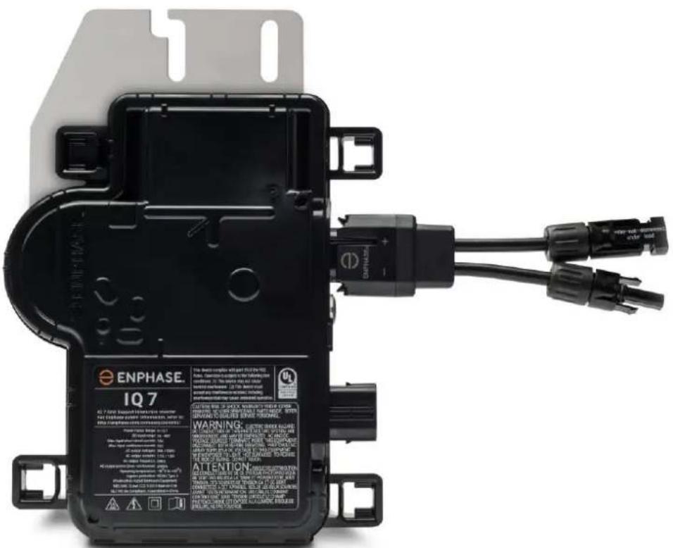
The Enphase IQ 7 Micro is compatible with 60-cell PV modules, and the IQ 7+ Micro supports PV modules with 60 or 72 Cells. The IQ 7X requires a 96-cell PV module. All of them install quickly and easily. The microinverter housing is designed for outdoor installation and complies with the IP67 environmental enclosure rating standard:

IP67 rating definition: Indoor or outdoor use primarily to provide a degree of protection against hose-directed water, the entry of water during occasional temporary submersion at a limited depth, and damage from external ice formation
The Enphase Q Cable is available in multiple connector spacing options for landscape and portrait orientations in 60 and 72-cell PV modules to meet varying site requirements. For Enphase Q Cable ordering information, see “Enphase Q Cable Planning and Ordering” on page 27.
Compatibility
The Enphase IQ Series Micros are electrically compatible with PV modules as listed in the following table. For specifications, see “Technical Data” on page 28 of this manual. You can refer to the Enphase Compatibility Calculator at: module-compatibility to verify PV module electrical compatibility. To ensure mechanical compatibility, be sure to order the correct connector type for both microinverter and PV module from your distributor.

WARNING: Risk of fire. The PV module DC conductors must be labeled "PV Wire" or "PV Cable" to comply with NEC for Ungrounded PV Power Systems.
| Microinverter model | Connector type | PV module cell count |
| IQ7-60-2-INT | MC-4 locking type | Pair only with 60-cell modules |
| IQ7PLUS-72-2-INT | MC-4 locking type | Pair with 60 or 72-cell modules |
| IQ7X-96-2-INT | MC-4 locking type | Pair only with 96-cell modules |

NOTE: Some Enphase Microinverters will not begin exporting power until the Envoy is installed and has detected all of the microinverters at the site. In addition, the grid profile may need to be configured and the Envoy must have propagated these settings to the microinverters. For instructions on this procedure, refer to the Envoy Installation and Operation Manual at enphase.com/support.
Grounding Considerations
The IQ Series Micros do not require grounding electrode conductors (GEC) or equipment grounding conductors (EGC). Your Authority Having Jurisdiction (AHJ) may require you to bond the mounting bracket to the racking. If so, use earthing hardware or star washers. The microinverter itself has a Class II double-insulated rating, which includes ground fault protection (GFP). To support GFP, use only PV modules equipped with DC cables labeled PV Wire or PV Cable.
Branch Circuit Capacity
Plan your AC branch circuits to meet the following limits* for maximum number of microinverters per branch when protected with a 20-amp over-current protection device (OCPD). For multiphase installations, use a 3-pole 20A OCPD.
| Maximum* IQ Micros per AC branch circuit | |||
| Microinverter model | IQ 7 Micros | IQ 7+ Micros | IQ 7X Micros |
| Single-phase | 16 | 13 | 12 |
| Multiphase | 48 | 39 | 36 |

NOTE: *Limits may vary. Refer to local requirements to define the number of microinverters per branch in your area
Utility Service Requirements
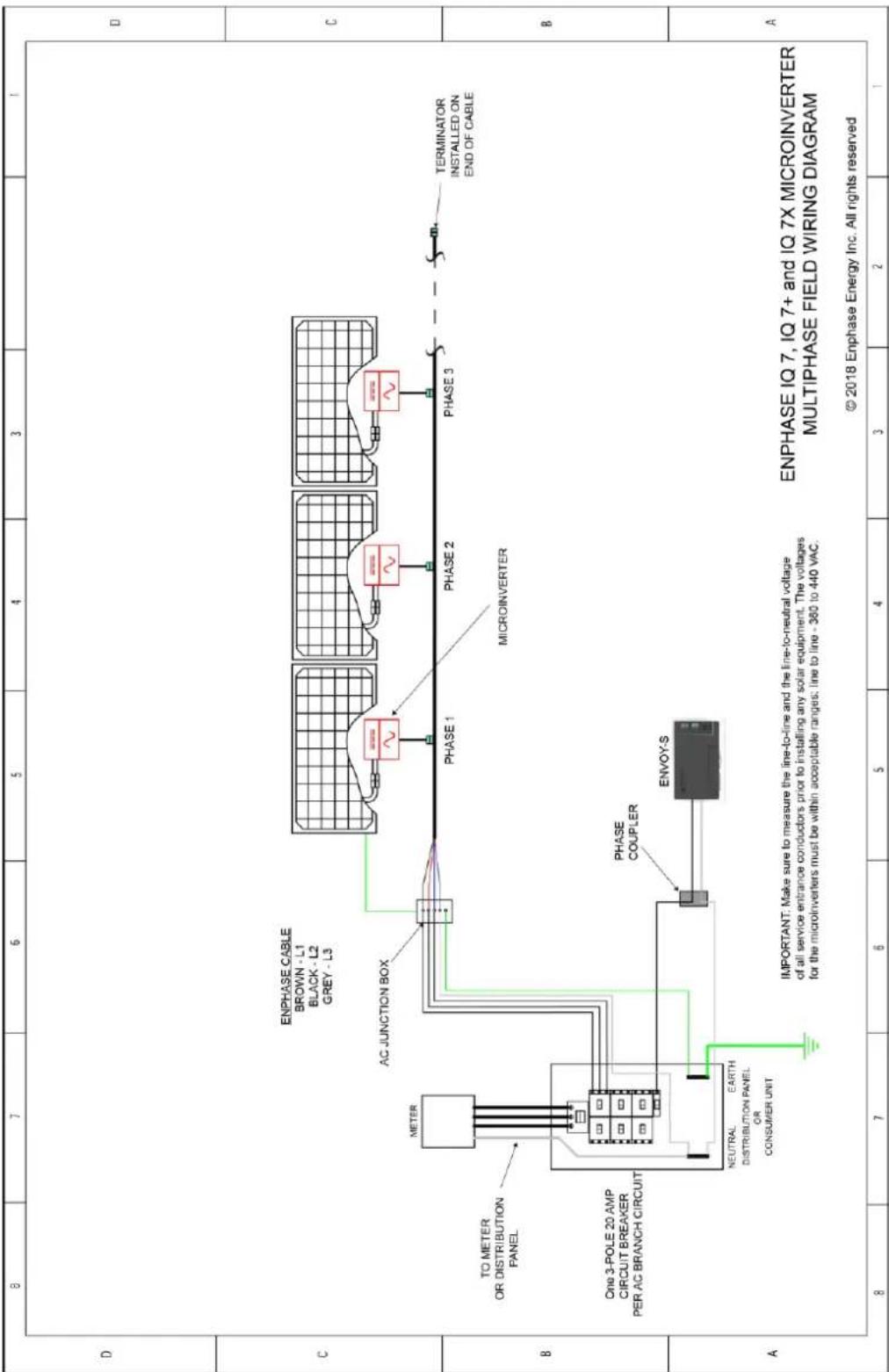
The Enphase Microinverter works with single-phase 230 VAC service. Measure AC line voltage at the electrical utility connection to confirm that it is within the ranges shown:
| Single-Phase Service | Three-Phase Service | ||
| L1 to N | 207 to 253 VAC | L1 to L2 to L3 | 360 to 440 VAC |
| L1, L2, L3 to N | 207 to 253 VAC | ||
Wire Lengths and Voltage Rise
When planning the system, you must select the appropriate AC conductor size to minimize voltage rise. Select the correct wire size based on the distance from the beginning of the microinverter AC branch circuit to the breaker in the load center. Enphase recommends a voltage rise total of less than 2% for the sections from the microinverter AC branch circuit to the breaker in the load center.
Enphase provides guidance about choosing wire size and maximum conductor lengths in the Voltage Rise Technical Brief at enphase.com/support. Refer to this brief for voltage rise values in Enphase Q Cables and on how to calculate voltage rise in other wire sections of the system.
Standard guidelines for voltage rise on feeder and AC branch circuit conductors might not be sufficient for microinverter AC branch circuits that contain the maximum allowable microinverters. This is due to high inherent voltage rise on the AC branch circuit.

Best practice: Center-feed the branch circuit to minimize voltage rise in a fully-populated branch. This practice greatly reduces the voltage rise as compared with an end-fed branch. To center-feed a branch, divide the circuit into two sub-branch circuits protected by a single OCPD.
Lightning and Surge Suppression
Enphase Microinverters have integral surge protection, greater than most traditional inverters. However, if the surge has sufficient energy, the protection built into the microinverter can be exceeded, and the equipment can be damaged. For this reason, Enphase recommends that you protect your system with a lightning and/or surge suppression device. In addition to having some level of surge suppression, it is also important to have insurance that protects against lightning and electrical surges.

NOTE: Protection against lightning and resulting voltage surge must be in accordance with local standards.
Parts and Tools Required
In addition to the microinverters, PV modules, and racking, you will need the following:
Enphase Equipment
- Enphase Envoy-S gateway required to monitor solar production. For installation information, refer to the Enphase Envoy-S Installation and Operations Manual.
- Enphase Installer Toolkit Download the Enphase Installer Toolkit mobile app and open it to log in to your Enlighten account. With this app, you can scan microinverter serial numbers and connect to the Envoy-S to track system installation progress. To download, go to enphase.com/toolkit or scan the QR code at right.
- Enphase Q Relay, single phase (Q-RELAY-1P-INT) or Enphase Q Relay, multiphase (Q-RELAY-3P-INT)
- Tie wraps or Cable Clips (ET-CLIP-100)
- Enphase Sealing caps (Q-SEAL-10) for any unused drops on the Enphase Q Cable (optional)
- Enphase Terminator (Q-TERM-R-10 for single phase or Q-TERM-3P-10 for multiphase)
One for each AC cable segment end; typically two needed per branch circuit.
• Enphase Disconnect Tool (Q-DISC-10) - Enphase Q Cable:
| Cable Model | Connector Spacing | PV Module Orientation | Connector Count per box |
| Single-phase | |||
| Q-25-10-240 | 1.3m | Portrait | 240 |
| Q-25-17-240 | 2.0m | Landscape (60- and 96- cell) | 240 |
| Q-25-20-200 | 2.3m | Landscape (72-cell) | 200 |
| Multiphase | |||
| Q-25-10-3P-200 | 1.3m | Portrait (all) | 200 |
| Q-25-17-3P-160 | 2.0m | Landscape (60- and 96-cell) | 160 |
| Q-25-20-3P-160 | 2.3m | Landscape (72-cell) | 160 |
- Raw Q Cable: (Q-25-RAW-300 for single-phase, Q-25-RAW-3P-300 for multiphase) Length 300 meters. Raw cable with no connectors. (optional)
Other Items
- Field Wireable Connectors (Q-CONN-R-10M and Q-CONN-R-10F): optional male and female connectors
• Number 2 and 3 screwdrivers - Wire cutters, voltmeter
- Torque wrench, sockets, wrenches for mounting hardware

Enphase Microinverter Installation
Installing the Enphase IQ Series Micros involves several key steps. Each step listed here is detailed in the following pages.
Step 1: Position the Enphase Q Cable
Step 2: Position the Junction Box
Step 3: Mount the Microinverters
Step 4: Create an Installation Map
Step 5: Manage the Cabling
Step 6: Connect the Microinverters
Step 7: Terminate the Unused End of the Cable
Step 8: Complete Installation of the Junction Box
Step 9: Connect the PV Modules
Step 10: Energize the System

text_image
Terminator DC connectors AC connector Enphase Q Cable Tie wraps or cable clips Enphase IQ Series Micros AC junction box or isolatorStep 1: Position the Enphase Q Cable
A. Plan each cable segment to allow drop connectors on the Enphase Q Cable to align with each PV module. Allow extra length for slack, cable turns, and any obstructions.
B. Mark the approximate centers of each PV module on the PV racking.
C. Lay out the cabling along the installed racking for the AC branch circuit.
D. Cut each segment of cable to meet your planned needs.

WARNING: When transitioning between rows, secure the cable to the rail to prevent cable damage or connector damage. Do not count on connector to withstand tension.
Step 2: Position the Junction Box
A. Verify that AC voltage at the site is within range.
| Single-Phase Service | Three-Phase Service | ||
| L1 to N | 207 to 253 VAC | L1 to L2 to L3 | 360 to 440 VAC |
| L1, L2, L3 to N | 207 to 253 VAC | ||
B. Install a junction box at a suitable location on the racking.
C. Provide an AC connection from the junction box back to the electricity network using equipment and practices as required by local jurisdictions.
Step 3: Mount the Microinverters
A. If the Enphase DC bulkhead connectors are not already attached to the microinverters, attach them now. Make sure they are fully seated.
B. Mount the microinverter bracket side up (as shown) and under the PV module, away from rain and sun. Allow a minimum of 1.9 cm between the roof and the microinverter. Also allow 1.3 cm between the back of the PV module and the top of the microinverter.

WARNING: Install the microinverter under the PV module to avoid direct exposure to rain, UV and other harmful weather events. Do not mount the microinverter upside down.
C. Torque the microinverter fasteners as follows. Do not over torque.
- 6 mm mounting hardware: 5 N m
- 8 mm mounting hardware: 9 N m
- When using UL 2703 mounting hardware, use the manufacturer's recommended torque value

text_image
Recommended torque Value DC Connector AC ConnectorStep 4: Create an Installation Map
The Enphase Installation Map is a diagram of the physical location of each microinverter in your PV installation. Copy or use the blank map on page 36 to record microinverter placement for the system or provide your own layout if you require a larger or more intricate installation map.
Each Enphase Microinverter, Envoy, and Battery have a removable serial number label. Build the installation map by peeling the serial number labels from the microinverter mounting plates and placing the labels on the map. You will also place the Enphase Envoy-S and IQ Battery serial number on the map after installation.
After you have created the installation map, use the Enphase Installer Toolkit mobile app to record serial numbers and configure the system.
For Installer Toolkit details refer to "Detect the Microinverters" in the help topics of the Installer Toolkit app.
A. Peel the removable serial number label from each microinverter and affix it to the respective location on the paper installation map.
B. Peel the label from the Envoy-S and any Enphase Battery, if installed) and affix it to the installation map.
C. Always keep a copy of the installation map for your records.

text_image
Panel Group: Azimuth Tilt: sheet of ____ To Sheet: ____ A B C D E F G H J K L M Scan completed map and upload to the Activation Ensoy Serial Label page online at www.enphaseenergys.com. Use this map to build the virtual array in Enlighten Array Buildle: To Sheet: ____ [ e ] enphase ENPHASEGTY INSTALLATION MAP To Sheet: ____ N J.E.W. (###) (###) Affix serial number labelsStep 5: Manage the Cabling
A. Use cable clips or tie wraps to attach the cable to the racking. Leave no more than 1.8 m between cable clips or tie wraps.
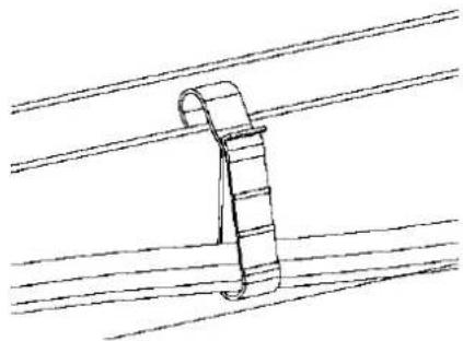
natural_image
Simple line drawing of a cable or wire clamp hanging from parallel lines (no text or symbols)Cable clip
B. Dress any excess cabling in loops so that it does not contact the roof. Do not form loops smaller than 12 cm in diameter.

WARNING: Tripping Hazard. Loose cables can become a tripping hazard. Dress the Enphase Q Cable to minimize this potential.
Step 6: Connect the Microinverters
A. Connect the microinverter. Listen for a click as the connectors engage. B. Cover any unused connector with Enphase Sealing Caps. Listen for a click as the connectors engage.
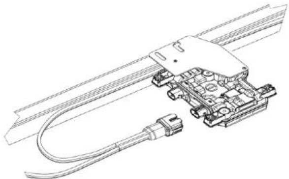
natural_image
Technical line drawing of a mechanical assembly with coiled cable and connector (no text or symbols)
WARNING: Risk of electric shock. Risk of fire. Install sealing caps on all unused AC connectors as these connectors become live when the system is energized. Sealing caps are required for protection against moisture ingress.

NOTE: If you need to remove a sealing cap, you must use the Enphase Disconnect Tool. See "Disconnect a Microinverter" on page 24.
Step 7: Terminate the Unused End of the Cable
Terminate the unused end of the Enphase Q Cable as follows:
| Single-phase Q Cable | Three-phase Q Cable | ||
| A. Remove 13 mm of the cable sheath from the conductors.Use the terminator body loop to measure. | 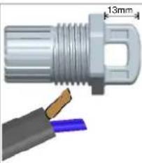 | A. Remove 20 mm of the cable sheath from the conductors. | 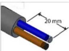 |
| B. Slide the hex nut onto the cable. The grommet inside the terminator body must remain in place. |  | B. Slide the hex nut onto the cable. The grommet inside the terminator body must remain in place. | 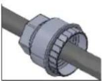 |
| C. Insert the cable into the terminator body so that the two wires land on opposite sides of the internal separator. | 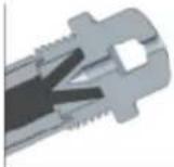 | C. Insert the cable into the terminator body so that the four wires land on separate sides of the internal separator. | 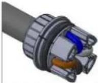 |
| D. Insert a screwdriver into the slot on the top of the terminator to hold it in place. Hold the terminator body stationary with the screwdriver and turn only the hex nut to prevent the conductors from twisting out of the separator.Torque the nut to 7.0 Nm. | 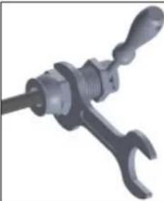 | D. Bend the wires down into the recesses of the terminator body and trim as needed.Place the cap over the terminator body. Insert a screwdriver into the slot on the terminator cap to hold it in place.Rotate the hex nut with your hand or a wrench until the latching mechanism meets the base. Do not over torque. |  |
| E. Attach the terminated cable end to the PV racking with a cable clip or tie wrap so that the cable and terminator do not touch the roof. | E. Attach the terminated cable end to the PV racking with a cable clip or tie wrap so that the cable and terminator do not touch the roof. | ||


NOTE: Turn only the hex nut to prevent conductors from twisting out of the separator.
WARNING: The terminator cannot be re-used. If you unscrew the nut, you must discard the terminator.
Step 8: Complete Installation of the Junction Box
A. Connect the Enphase Q Cable into the junction box.
B. Refer to the wiring diagrams on page 38 for more information. Q Cable uses the following color code:
| Single-Phase | Three-Phase |
| Brown – L1Blue – N | Brown – L1Black – L2Grey – L3Blue – N |

NOTE: The Q Cable internally rotates L1, L2, and L3 to provide balanced 400 VAC (three-phase), thus alternating phases between microinverters.
NOTE: Minimise the number of unused Q Cable connectors with three-phase systems. When cable connectors are left unused on a three-phase system, it creates a phase imbalance on the branch circuit. If multiple cable connectors are skipped over multiple branch circuits, the imbalance can multiply.
Step 9: Connect the PV Modules

WARNING: Electrical shock hazard. The DC conductors of this photovoltaic system are ungrounded and may be energized.
A. Connect the DC leads of each PV module to the DC input connectors of the corresponding microinverter.
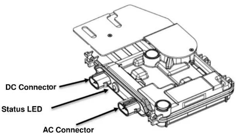
text_image
DC Connector Status LED AC ConnectorB. Check the LED on the connector side of the microinverter. The LED flashes six times when DC power is applied.
C. Mount the PV modules above the microinverters.
Step 10: Energize the System
A. Turn ON the AC disconnect or circuit breaker for the branch circuit.
B. Turn ON the main utility-grid AC circuit breaker. Your system starts producing power after a five-minute wait time.
C. Check the LED on the connector side of the microinverter:
| LED color | Indicates |
| Flashing green | Normal operation. AC grid function is normal there is communication with the Envoy-S. |
| Flashing orange | The AC grid is normal but there is no communication with the Envoy-S. |
| Flashing Red | The AC grid is either not present or not within specification. |
| Solid Red | There is an active “DC Resistance Low, Power Off Condition.” To reset, see “DC Resistance Low – Power Off Condition” on page 21. |
Set Up and Activate Monitoring
Refer to the Enphase Envoy-S Quick Install Guide to install the Envoy-S and set up system monitoring and grid management functions. This guide leads you through the following:
- Connecting the Envoy
- Detect devices
- Connecting to Enlighten
- Registering the system
• Building the virtual array

NOTE: When the utility requires a profile other than the profile resident on the microinverter, you must select an appropriate grid profile for your installation. You can set the grid profile through Enlighten, during system registration, or through Installer Toolkit at any time. You must have an Enphase Envoy to set or change the grid profile. For more information on setting or changing the grid profile, refer to the Enphase Envoy-S Installation and Operation Manual at enphase.com/support.
Troubleshooting
Follow all the safety measures described throughout this manual. Qualified personnel can use the following troubleshooting steps if the PV system does not operate correctly.

WARNING: Risk of electric shock. Do not attempt to repair the Enphase Microinverter; it contains no user-serviceable parts. If it fails, contact Enphase customer service to obtain an RMA (return merchandise authorization) number and start the replacement process.
Status LED Indications and Error Reporting
The following section describes LED indications.
LED Operation
| LED color | Indicates |
| Flashing green | Normal operation. AC grid function is normal there is communication with the Envoy-S. |
| Flashing orange | The AC grid is normal but there is no communication with the Envoy-S. |
| Flashing red | The AC grid is either not present or not within specification. |
| Solid red | There is an active “DC Resistance Low, Power Off Condition.” To reset, see “DC Resistance Low – Power Off Condition” on page 21. |
The status LED on each microinverter lights green about six seconds after DC power is applied. It remains lit solid for two minutes, followed by six green blinks. After that, red blinks indicate that no grid is present if the system is not yet energized.
Any short red blinks after DC power is first applied to the microinverter indicate a failure during microinverter startup.
DC Resistance Low – Power Off Condition
For all IQ Series models, a solid red status LED when DC power has been cycled indicates the microinverter has detected a DC Resistance Low – Power Off event. The LED will remain red and the fault will continue to be reported by the Envoy until the error has been cleared.
An insulation resistance (IR) sensor in the microinverter measures the resistance between the positive and negative PV inputs to ground. If either resistance drops below a threshold, the microinverter stops power production and raises this condition. This may indicate defective module insulation, defective wiring or connectors, moisture ingress, or a similar problem. Although the cause may be temporary, this microinverter condition persists until the sensor is manually reset.
An Envoy-S is required to clear this condition. The condition clears on operator command unless its cause is still present.
If a microinverter registers a “DC Resistance Low - Power Off” condition, you can attempt to clear this condition. If the condition does not clear after you perform the following procedure, contact Customer Support at https://enphase.com/en-us/support/global-contact.
There are two ways to send a clear message to the microinverter. Note that the condition will not clear after sensor reset if the cause of the failure is still present. If the condition persists, contact your installer or Enphase for possible replacement.
Method 1: Clear this Error Using Enlighten
- Log in to Enlighten and access the system.
- Click the Events tab. The next screen shows a current "DC Resistance Low - Power Off" condition for the system.
- Click DC Resistance Low - Power Off.
- Where "n" is the number of affected devices, click n devices (show details).
- Click the serial number of the affected microinverter.
- Click Reset DC Resistance Low - Power Off Sensor.
The system displays, "A DC Resistance Low- Power Off reset task was issued on [date and time] for this microinverter and is still pending."
Method 2: Use Installer Toolkit to Clear the Condition
On the list of detected microinverters, a green dot or red square appears to the left of each microinverter serial number. A green dot indicates Status OK. A red square indicates an event for that microinverter.
- Tap the to the left of the serial number to view details for a microinverter event.
- If the microinverter status shows that there is an active DC Resistance Low – Power Off condition, tap the to send the clear message to the affected microinverter. The app then indicates that a clear message was sent.

text_image
121206041745 Installed Nov 29, 2013 09:35 PM Status: DC Resistance Low - Power Off Last Report: 225 W 07/17/2015 11:03 AM Assigned via provisioning Comm Level: Grid Profile: Profile Set (VDE0126 default) Part Number: 800-00090-r04 Running Image: 520-00042-r01-v98.17.09 Updated 10/22/2013 09:35 PM Parameter Table: Not Available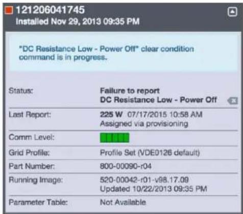
text_image
121206041745 Installed Nov 29, 2013 09:35 PM "DC Resistance Low - Power Off" clear condition command is in progress. Status: Failure to report DC Resistance Low - Power Off Last Report: 225 W 07/17/2015 10:58 AM Assigned via provisioning Comm Level: Grid Profile: Profile Set (VDE0126 default) Part Number: 800-00090-r04 Running Image: 520-00042-r01-v98.17.09 Updated 10/22/2013 09:35 PM Parameter Table: Not AvailableOther Faults
All other faults are reported to the Envoy. Refer to the Enphase Envoy-S Installation and Operation Manual at enphase.com/support for troubleshooting procedures.
Troubleshoot an Inoperable Microinverter
To troubleshoot an inoperable microinverter, follow the steps in the order shown.

WARNING: Risk of electric shock. Always de-energize the AC branch circuit before servicing. Never disconnect the DC connectors under load.

WARNING: The Enphase Microinverters are powered by DC power from the PV modules. Make sure you disconnect the DC connections and reconnect DC power and then watch for the solid green about six seconds after connection to DC power.
A. Make sure AC breakers and disconnects are closed.
B. Check the connection to the utility grid and verify that the utility voltage is within allowable ranges.
C. Verify that AC line voltages at all solar power circuit breakers at the load center and subpanels are within the ranges shown in the following table.
D. Verify that AC line voltage at the junction box for each AC branch circuit at the site is within range:
| Service Type and Voltage: L to N | |
| 230 V Single-Phase | 207 to 253 VAC |
D. Using an Enphase disconnect tool, disconnect the AC cable for the microinverter in question from the Enphase Q Cable.
E. Verify that utility power is present at the microinverter by measuring line to line and line to ground at the Enphase Q Cable connector.
F. Visually check that the AC branch circuit connections (Enphase Q Cable and AC connections) are properly seated. Reseat if necessary. Check also for damage, such as rodent damage.
G. Make sure that any upstream AC disconnects, as well as the dedicated circuit breakers for each AC branch circuit, are functioning properly and are closed.
H. Disconnect and re-connect the DC PV module connectors. The status LED of each microinverter will light solid green a few seconds after connection to DC power and then blink green six times to indicate normal start-up operation about two minutes after connecting to DC power. The LED subsequently resumes normal operation if the grid is present. See page 21 for normal LED operation.
I. Attach an ammeter clamp to one conductor of the DC cables from the PV module to measure microinverter current. This will be under one amp if AC is disconnected.
J. Verify the PV module DC voltage is within the allowable range shown in "Specifications" on page 29 of this manual.
K. Swap DC leads with a known good, adjacent PV module. If after checking Enlighten periodically (this may take up to 30 minutes), the problem moves to the adjacent module, this indicates that the PV module isn't functioning correctly. If it stays in place, the problem is with the original microinverter. Contact Enphase Customer Support for help in reading the microinverter data and for help in obtaining a replacement microinverter, if needed.
L. Check the DC connections between the microinverter and the PV module. The connection may need to be tightened or reseated. If the connection is worn or damaged, it may need replacement.
M. Verify with your utility that line frequency is within range.
N. If the problem persists, contact Customer Support at https://enphase.com/en-us/support/global-contact.
Disconnect a Microinverter
If problems remain after following the troubleshooting steps listed previously, contact Customer Support at https://enphase.com/en-us/support/global-contact.
If Enphase authorizes a replacement, follow the steps below. To ensure the microinverter is not disconnected from the PV modules under load, follow the disconnection steps in the order shown:
A. De-energize the AC branch circuit breaker.
B. Enphase AC connectors are tool-removable only. To disconnect the microinverter from the Enphase Q Cable, insert the disconnect tool and remove the connector.
C. Cover the PV module with an opaque cover.
D. Using a clamp-on meter, verify there is no current flowing in the DC wires between the PV module and the microinverter. If current is still flowing, check that you have completed steps one and two above.

NOTE: Take care when measuring DC current as most clamp-on meters must be zeroed first and tend to drift with time.
E. Disconnect the PV module DC wire connectors from the microinverter using the Enphase disconnect tool.
F. If present, loosen and/or remove any bonding hardware.
G. Remove the microinverter from the PV racking.

WARNING: Risk of electric shock. Risk of fire. Do not leave any connectors on the PV system disconnected for an extended period. If you do not plan to replace the microinverter immediately, you must cover any unused connector with a sealing cap.
Install a Replacement Microinverter
A. When the replacement microinverter is available, verify that the AC branch circuit breaker is de-energized.
B. Mount the microinverter bracket side up and under the PV module, away from rain and sun. Allow a minimum of 1.9cm between the roof and the microinverter. Also allow 1.3cm between the back of the PV module and the top of the microinverter

WARNING: Risk of equipment damage. Mount the microinverter under the PV module.
- Install the microinverter under the PV module to avoid direct exposure to rain, UV, and other harmful weather events.
• Always install the microinverter bracket side up. - Do not mount the microinverter upside down.
- Do not expose the AC or DC connectors (on the Enphase Q Cable connection, PV module, or the microinverter) to rain or condensation before the connectors are mated.
C. Torque the mounting fasteners to the values shown. Do not over torque.
- 6 mm mounting hardware: 5 N m
- 8 mm mounting hardware: 9 N m
- When using earthing mounting hardware, use the manufacturer's recommended torque value
D. If you are using bonding hardware, the old bonding hardware should be discarded, and new bonding hardware must be used when installing the replacement microinverter.
E. Connect the microinverter to the Q Cable connector. Listen for a click as connectors engage.
F. Connect the DC leads of each PV module to the DC input connector of the microinverter.
G. Re-mount the PV module above the microinverter.
H. Energize the AC branch circuit breaker and verify operation of the replacement microinverter by checking the Status LED on the connector side of the microinverter.
I. Use the Installer Toolkit mobile app to delete the old microinverter serial number from the Enphase Envoy-S database. In Installer Toolkit, once connected to the Envoy:
a. Tap Micros > Manage.
b. Tap the checkbox to the right of the microinverter serial number replaced.
c. Tap to delete the microinverter from the Envoy-S database.
J. Add the new microinverter serial number to the Envoy database by initiating a device scan using one of the following methods:
a. Method 1: Initiate a scan using the Installer Toolkit mobile app
- In Installer Toolkit, once connected to the Envoy-S, navigate to the Overview screen.
- From the Overview screen, tap Detected > Start Device Scan to start a new 30-minute device scan.
- If device scanning on the Envoy-S is inhibited, the app displays Scan Inhibited. If you need to add more microinverters to the system when device scanning is inhibited on the Envoy-S, you must use the Installer Toolkit scanning tool to provision them on the Envoy-S, rather than using the Envoy-S's device scanning function to discover them. If this is not possible and you need to enable device scanning on the Envoy-S, contact Customer Support at https://enphase.com/en-us/support/global-contact.
b. Method 2: Use an Envoy-S
- Press the Device Scan button on the Envoy-S. The Envoy-S begins a 15-minute scan to identify all of the microinverters deployed at the site. The Microinverter Communications LED flashes green during the scan.
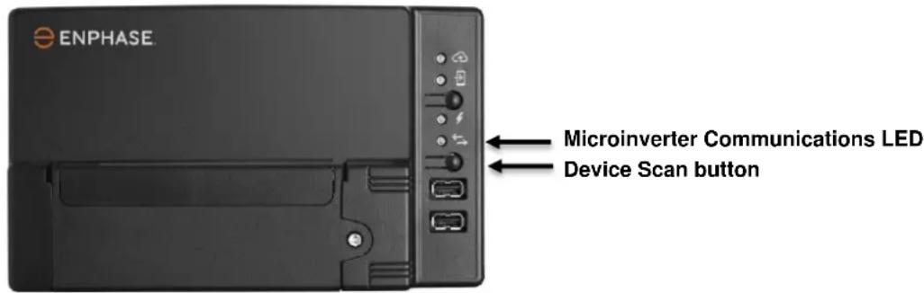
text_image
ENPHASE Microinverter Communications LED Device Scan buttonK. Log in to Enlighten to use Enlighten's Array Builder to add the newly detected microinverter to the virtual array.
L. Ship the old microinverter to Enphase using the supplied return-shipping label.
Ordering Replacement Parts
Replacement adaptors for the Microinverter include:
• Q-DCC-2: Cable Assembly, DC adaptor to MC-4
• Q-DCC-5: Cable Assembly, DC adaptor to Amphenol UTX
These parts are available from your Enphase distributor.
Enphase Q Cable Planning and Ordering
The Enphase Q Cable is a continuous length of double insulated, outdoor-rated cable with integrated connectors for microinverters. These connectors are preinstalled along the Q Cable at intervals to accommodate varying PV module widths. The microinverters plug directly into the cable connectors.
The cabling is compatible with a variety of PV racking systems. For a list of approved PV racking systems, refer to the PV Racking Compatibility document on the Enphase website at enphase.com/support.
Connector Spacing Options
Q Cable is available in three connector spacing options. The gap between connectors on the cable can be 1.3 meters, 2.0 meters, or 2.3 meters. The 1.3 meter spacing is best suited for connecting PV modules installed in portrait orientation, while the 2.0 meter and 2.3 meter spacing allows you to install 60-cell and 72-cell PV modules in landscape orientation, respectively.
Cabling Options
Ordering options include:
| Cable Model | Connector spacing | PV module orientation | Connector count per box |
| Q-25-10-240 | 1.3m | Portrait | 240 |
| Q-25-17-240 | 2.0m | Landscape (60-cell) | 240 |
| Q-25-20-200 | 2.3m | Landscape (72-cell) | 200 |
The Cabling System is flexible enough to adapt to almost any solar design. To determine the cable type, you need, apply the following considerations:
- When mixing PV modules in both portrait and landscape orientation, you may need to transition between cable types. See the preceding table for available cable types.
• To transition between cable types, install a Field Wireable connector pair. - In situations where portrait modules are widely spaced, you may need to use landscape spaced cables for the portrait-oriented PV modules and create loops of excess cable, if needed.

WARNING: Do not form loops smaller than 12 cm (4.75") in diameter.
Enphase Q Cable Accessories
The Enphase Q Cable is available with several accessory options for ease of installation, including:
- Raw Q Cable: (Q-25-RAW-300) Length 300 meters. Raw cable with no connectors.
- Field Wireable connectors (male): (Q-CONN-R-10M) Make connections from any open female Q connector or Field Wireable female connector
- Field Wireable connectors (female): (Q-CONN-R-10F) Make connections from any Q Cable open connector or Field Wireable male connector
- Cable clips: (E-CLIP-100) Used to fasten cabling to the racking or to secure looped cabling
- Disconnect Tool: (Q-DISC-10) Disconnect tool for Q Cable connectors, DC connectors, and AC module mount
- Q Cable sealing caps (female): (Q-SEAL-10) One needed to cover each unused connector on the cabling
• Terminator: (Q-TERM-R-10) Terminator cap for cut cable ends
Technical Data
Technical Considerations
Be sure to apply the following when installing the Enphase IQ-Series Micro System:

WARNING: Risk of equipment damage. You must match the DC operating voltage range of the PV module with the allowable input voltage range of the Enphase Microinverter.

WARNING: Risk of equipment damage. The maximum open circuit voltage of the PV module must not exceed the specified maximum input voltage of the Enphase Microinverter.
- PV modules must have conductors labeled "PV Wire" or "PV Cable" to comply with NEC for Ungrounded PV Power Systems.
- Verify that the voltage and current specifications of the PV module match those of the microinverter.
- The maximum short circuit current rating of the PV module must be equal to or less than the maximum input DC short circuit current rating of the microinverter.
The output voltage and current of the PV module depends on the quantity, size and temperature of the PV cells, as well as the insolation on each cell. The highest PV module output voltage occurs when the temperature of the cells is the lowest and the PV module is at open circuit (not operating).
Compliance Data
Anti-Islanding
Enphase IQ 7 Series Microinverters use the following anti-islanding functions:
• Rate of Change of Frequency (RoCoF)
- Vector Shift
• Harmonic injection (soon to be replaced by VAR injection)
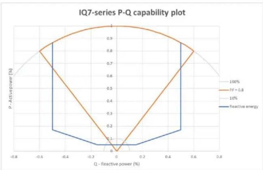
PQ Capability Curve
If needed, Enphase IQ 7 Series Microinverters have the capability to absorb or inject reactive power, provided that current and voltage ratings are not exceeded. Below is an active power (P) capabilities curve relative to reactive power (Q) related to the power rating in the operating voltage range for Enphase IQ 7 Series.
• Maximum power factor (pf)
adjustability = -0.8
to +0.8
- Reactive power capability = ± 50% (over / under excited) Provision or absorption of reactive energy
line
| Q - Reactive power (%) | P - Active power (%) | | ---------------------- | -------------------- | | -0.8 | 0.6 | | -0.6 | 0.8 | | -0.4 | 0.9 | | -0.2 | 0.95 | | 0.0 | 1.0 | | 0.2 | 0.95 | | 0.4 | 0.9 | | 0.6 | 0.8 | | 0.8 | 0.6 |Specifications
See specifications in the following tables for:
• IQ7-60-2-INT Microinverter
• IQ7PLUS-72-2-INT Microinverter
- Enphase Q Cable
IQ7-60-2-INT Microinverter Specifications
| Enphase IQ7-60-2-INT Microinverter Parameters | ||||
| Topic | Unit | Min | Typical | Max |
| DC Parameters | ||||
| Commonly used module pairings1 | 235 W – 350+ W | |||
| Peak power tracking voltage | V | 27 | 37 | |
| Operating voltage range | V | 16 | 48 | |
| Maximum input DC voltage | V | 48 | ||
| Minimum / maximum start voltage | V | 22 | 48 | |
| Maximum DC input short circuit current (module lsc) | A | 15 | ||
| Overvoltage class DC port | II | |||
| DC Port backfeed under single fault | A | 0 | ||
| PV array configuration | 1x1 ungrounded array; No additional DC side protection required; AC side protection requires max 20A per branch circuit | |||
| AC Parameters | ||||
| Maximum continuous AC output power (-40°C to +65°C) | VA | 240 | ||
| Peak output power | VA | 250 | ||
| Power factor (adjustable) | 0.8 leading0.8 lagging | |||
| Nominal AC output voltage range2230 VAC (single phase) | Vrms | 184 | 276 | |
| Nominal output current230 VAC (single phase) | Arms | 1.04 | ||
| Nominal frequency | Hz | 50 | ||
| Extended frequency range | Hz | 45 | 55 | |
| Overvoltage class AC port | III | |||
| AC port backfeed under single fault | A | 0 | ||
| Power factor setting | 1.0 | |||
| Miscellaneous Parameters | ||||
| Maximum3 microinverters per 20A (max) AC branch circuit 230 VAC (single phase) | 16 | |||
| EN 50530 (EU) weighted efficiency 230 VAC (single phase) | % | 96.5 | ||
| Static MPPT efficiency (weighted, ref EN 50530) | % | 99.5 | ||
| Total harmonic distortion | % | 5 | ||
| Ambient temperature range | °C | -40 | +65 | |
| Night tare loss | mW | 50 | ||
| Storage temperature range | °C | -40 | +85 | |
| Features and Specifications | ||||
| Compatibility | Pairs with most 60-cell PV modules (the PV module DC conductors must be labeled "PV Wire" or "PV Cable" to be compliant for Ungrounded PV Power Systems) | |||
| Dimensions not including mounting bracket | 212 mm x 175 mm x 30.2 mm (approximate) | |||
| Connector type | MC-4 (or Amphenol H4 UTX with additional Q-DCC-5 adaptor) | |||
| Weight | 1.08 kg (2.38 lbs.) | |||
| Environmental category / UV exposure rating | IP67 / outdoor | |||
| Torque specifications for fasteners (Do not over torque) | 6 mm mounting hardware: 5 N m8 mm mounting hardware: 9 N mWhen using earthing hardware, use the manufacturer's recommended torque value | |||
| Cooling | Natural convection - no fans | |||
| Relative humidity range | 4% to 100% condensing | |||
| Approved for wet locations | Yes | |||
| Pollution degree | PD3 | |||
| Standard warranty term | enphase.com/warranty | |||
| Compliance | AS 4777.2, RCM, IEC/EN 61000-6-3, IEC/EN 62109-1, IEC/EN 62109-2 | |||
| Grounding | The DC circuit meets the requirements for ungrounded PV arrays. Ground fault protection (GFP) is integrated into the class II double insulated microinverter. | |||
| Monitoring | Enlighten Manager and MyEnlighten monitoring options require an Enphase Envoy-S | |||
| Communication | Power line | |||
| Integrated DC disconnect | The DC connector has been evaluated and approved for use as the load-break disconnect. | |||
| Integrated AC disconnect | The AC connector has been evaluated and approved for use as the load-break disconnect. | |||
IQ7PLUS-72-2-INT Microinverter Specifications
| IQ7PLUS-72-2-INT Microinverter Parameters | ||||
| Topic | Unit | Min | Typical | Max |
| DC Parameters | ||||
| Commonly used module pairings4 | W | 235 W - 440+ W | ||
| Peak power tracking voltage | V | 27 | 45 | |
| Operating range | V | 16 | 60 | |
| Maximum DC input voltage | V | 60 | ||
| Minimum / maximum start voltage | V | 22 | 60 | |
| Maximum DC input short circuit current (module lsc) | A | 15 | ||
| Overvoltage class DC port | II | |||
| DC Port backfeed under single fault | A | 0 | ||
| PV array configuration | 1 x 1 ungrounded array; No additional DC side protection required; AC side protection requires max 20 A per branch circuit | |||
| AC Parameters | ||||
| Maximum continuous AC output power (-40 to +65°C) | VA | 290 | ||
| Peak output power | VA | 295 | ||
| Power factor (adjustable) | 0.8 leading0.8 lagging | |||
| Nominal AC output voltage range5230 VAC (single phase) | Vrms | 184 | 276 | |
| Nominal output current230 VAC (single phase) | Arms | 1.26 | ||
| Nominal frequency | Hz | 50 | ||
| Extended frequency range | Hz | 45 | 55 | |
| Maximum AC output over current protection device | A | 20 | ||
| Overvoltage class AC port | III | |||
| AC port backfeed under single fault | A | 0 | ||
| Power factor setting | 1.0 | |||
IQ7PLUS-72-2-INT Microinverter Parameters
| Miscellaneous Parameters | ||||
| Maximum^6 microinverters per 20A (max) AC branch circuit 230 VAC (single phase) | 13 | |||
| EN 50530 (EU) weighted efficiency 230 VAC (single phase) | % | 96.5 | ||
| Static MPPT efficiency (weighted, ref EN 50530) | % | 99.5 | ||
| Total harmonic distortion | % | 5 | ||
| Ambient temperature range | °C | -40 | +65 | |
| Night tare loss | mW | 50 | ||
| Storage temperature range | °C | -40 | +85 | |
Features and Specifications
| Compatibility | Pairs with most 60 and 72-cell PV modules |
| Dimensions not including mounting bracket | 212 mm x 175 mm x 30.2 mm (approximate) |
| Connector type | MC-4 (or Amphenol H4 UTX with additional Q-DCC-5 adaptor) |
| Weight | 1.08 kg (2.38 lbs.) |
| Environmental category / UV exposure rating | IP67 / outdoor |
| Torque specifications for fasteners(Do not over torque) | 6 mm mounting hardware: 5 N m8 mm mounting hardware: 9 N mWhen using earthing hardware, use the manufacturer's recommended torque value |
| Cooling | Natural convection - no fans |
| Relative humidity range | 4% to 100% condensing |
| Approved for wet locations | Yes |
| Pollution degree | PD3 |
| Communication | Power line |
| Standard warranty term | enphase.com/warranty |
| Compliance | AS 4777.2, RCM, IEC/EN 61000-6-3, IEC/EN 62109-1, IEC/EN 62109-2 |
| Grounding | The DC circuit meets the requirements for ungrounded PV arrays. Ground fault protection (GFP) is integrated into the class II double insulated microinverter. |
| Monitoring | Enlighten Manager and MyEnlighten monitoring options require an Enphase Envoy-S |
| Integrated DC disconnect | The DC connector has been evaluated and approved for use as the load-break disconnect. |
| Integrated AC disconnect | The AC connector has been evaluated and approved for use as the load-break disconnect. |
IQ7X-96-2-INT Microinverter Specifications
| IQ7X-96-2-INT Microinverter Parameters | ||||
| Topic | Unit | Min | Typical | Max |
| DC Parameters | ||||
| Commonly used module pairings ^7 | W | 320 W - 460+ W | ||
| Peak power tracking voltage | V | 53 | 64 | |
| Operating range | V | 25 | 79.5 | |
| Maximum DC input voltage | V | 79.5 | ||
| Minimum / maximum start voltage | V | 33 | 79.5 | |
| Maximum DC input short circuit current (module lsc) | A | 10315 | ||
| Overvoltage class DC port | II | |||
| DC Port backfeed under single fault | A | 0 | ||
| PV array configuration | 1 x 1 ungrounded array; No additional DC side protection required; AC side protection requires max 20 A per branch circuit | |||
| AC Parameters | ||||
| Maximum continuous AC output power (-40 to +65°C) | VA | 315 | ||
| Peak output power | VA | 320 | ||
| Power factor (adjustable) | 0.8 leading0.8 lagging | |||
| Nominal AC output voltage range ^8 230 VAC (single phase) | Vrms | 184 | 276 | |
| Nominal output current230 VAC (single phase) | Arms | 1.37 | ||
| Nominal frequency | Hz | 50 | ||
| Extended frequency range | Hz | 45 | 55 | |
| Maximum AC output over current protection device | A | 20 | ||
| Overvoltage class AC port | III | |||
| AC port backfeed under single fault | A | 0 | ||
| Power factor setting | 1.0 | |||
IQ7X-96-2-INT Microinverter Parameters
| Miscellaneous Parameters | ||||
| Maximum^9 microinverters per 20A (max) AC branch circuit 230 VAC (single phase) | 12 | |||
| EN 50530 (EU) weighted efficiency 230 VAC (single phase) | % | 96.5 | ||
| Static MPPT efficiency (weighted, ref EN 50530) | % | 99.5 | ||
| Total harmonic distortion | % | 5 | ||
| Ambient temperature range | °C | -40 | +60 | |
| Night tare loss | mW | 50 | ||
| Storage temperature range | °C | -40 | +85 | |
Features and Specifications
| Compatibility | Pairs with 96-cell PV modules |
| Dimensions not including mounting bracket | 212 mm x 175 mm x 30.2 mm (approximate) |
| Connector type | MC-4 (or Amphenol H4 UTX with additional Q-DCC-5 adaptor) |
| Weight | 1.08 kg |
| Environmental category / UV exposure rating | IP67 / outdoor |
| Torque specifications for fasteners(Do not over torque) | 6 mm mounting hardware: 5 N m8 mm mounting hardware: 9 N mWhen using earthing hardware, use the manufacturer's recommended torque value |
| Cooling | Natural convection - no fans |
| Relative humidity range | 4% to 100% condensing |
| Approved for wet locations | Yes |
| Pollution degree | PD3 |
| Communication | Power line |
| Standard warranty term | enphase.com/warranty |
| Compliance | AS 4777.2, RCM, IEC/EN 61000-6-3, IEC/EN 62109-1, IEC/EN 62109-2 |
| Grounding | The DC circuit meets the requirements for ungrounded PV arrays. Ground fault protection (GFP) is integrated into the class II double insulated microinverter. |
| Monitoring | Enlighten Manager and MyEnlighten monitoring options require an Enphase Envoy-S |
| Integrated DC disconnect | The DC connector has been evaluated and approved for use as the load-break disconnect. |
| Integrated AC disconnect | The AC connector has been evaluated and approved for use as the load-break disconnect. |
Q Cable Specifications
| Specification | Value |
| Voltage rating | 600V |
| Voltage withstand test (kV/1min) | AC 3.0 |
| Max DC conductor resistance (20°C) (Ω/km) | 5.433 |
| Insulation resistance (20°C) | ≥20M (Ω/km) |
| System temperature range (ambient) | -40°C to +65°C |
| Cable temperature rating | 90°C Dry / 90°C Wet |
| Cable rating | DG |
| Certification | UL 3003, TC-ER equivalent |
| Flame rating | IEC 60332-1-2 |
| Cable conductor insulator rating | H07BQ-F |
| Environmental protection rating | IEC 60529 IP67 NEMA 6 |
| UV resistance | 720h |
| UV exposure rating | EN ISO 492-2 |
| Compliance | RoHS, OIL RES I, CE, UV Resistant |
| Maximum loop size | 12 cm |
Enphase Installation Map
| Panel Group / Groupe de modules /Gruppo di moduli / Modulgruppe / Modulegroep:Azimuth / Azimut:Tilt / Inclinaison / Inclinazione / Neigungswinkel / Helling:sheet / page / foglio / Blatt / pagina____/____ | Client / Cliente / Kunde / Cliënt: | Installer / Installateur / Installatore: | N SEW / N SEON S O W / N Z O W | |||||
| 1 | 2 | 3 | 4 | 5 | 6 | 7 | ||
| A | ||||||||
| B | ||||||||
| C | ||||||||
| D | ||||||||
| E | ||||||||
| F | ||||||||
| G | ||||||||
| H | ||||||||
| J | ||||||||
| K | ||||||||
| Envoy senal label /étiquette de numéro de série /etichette di serie Envoy/Serien Nummer / Label serienummer:ENPHASE. ENPHASE.COM INSTALLATION MAP / PLAN D'INSTALLATIONMAPPA INSTALLAZIONE / INSTALLATIONSPLANINSTALLATIE KAARTTo sheet / Vers la page / Al foglio / Zu Blatt / Naar pagina.© 2018 Enphase Energy Inc. All rights reserved. | ||||||||
Sample Wiring Diagram – single-phase:

text_image
D C B A 8 7 6 5 4 3 2 1 TO METER OR AC DISTRIBUTION PANEL METER SINGLE POLE 20 AMP CIRCUIT BREAKER PER BRANCH CIRCUIT NEUTRAL EARTH CONSUMER UNIT OR SUBPANEL JUNCTION BOX Q CABLE BROWN- L BLUE- N NOTE: Ground PV modules according to local requirements. TERMINATOR INSTALLED ON END OF CABLE NOTE: The IQ 7 Micro and the IQ 7+ Micro have integrated ground (earth) and double insulation, so no GEC or EGC is required. Verify that the DC circuit is isolated and insulated from ground (earth) and meets local requirements. UP TO 16 IQ 7 MICROS or 13 IQ 7+ MICROS OR 12 IQ 7X MICROS PER 230 AC BRANCH CIRCUIT ENVOY-S IMPORTANT: Make sure to measure the line-to-neutral voltage at the electrical utility connection prior to installing any solar equipment. The voltages for the 230 VAC rated microinverters must be within acceptable range (207 to 253 VAC). ENPHASE IQ 7 and IQ 7+ MICROINVERTER FIELD WIRING DIAGRAM © 2018 Enphase Energy Inc. All rights reservedSample Wiring Diagram – multiphase: