
EHG 77 - Hot plate ELECTROLUX - Free user manual and instructions
Find the device manual for free EHG 77 ELECTROLUX in PDF.

| Product Type | Gas Hob (Hotplate) |
| Brand | Electrolux |
| Model | EHG 77 |
| Dimensions (Width x Depth x Height above work surface) | 680 mm x 510 mm x 45 mm |
| Minimum Space Above Hotplate | 600 mm |
| Minimum Clearance from Rear Edge | 110 mm |
| Gas Connection | RC 1/2 (1/2" B.S.P.) |
| Electrical Supply | 1 mm² 3-core cable, 3 A fuse, 230 V ~ 50 Hz |
| Burners | Large rapid (11.5 MJ), Medium semi-rapid (6.5 MJ), Small auxiliary (8.7 MJ), Triple flame (17.3 MJ) |
| Burner Diameter Range | Large: 180-230 mm, Medium: 120-200 mm, Small: 80-160 mm, Triple: 220-260 mm |
| Gas Type (Factory Preset) | Natural Gas (1.00 kPa) |
| Convertible Gas Types | Universal LPG (2.75 kPa) and TLP |
| Ignition System | Spark ignition with push button |
| Safety Features | Safety valve (automatic gas shut-off), anti-tilt bracket, child lock on knobs |
| Cleaning | Use liquid detergent on cool surface; avoid abrasives. Removable burner caps and skirts |
| Installation Type | Built-in (cut-out 450 mm x 560 mm) |
| Environmental Compliance | Recyclable packaging; WEEE compliant |
| Warranty | Refer to data label; service by authorized personnel only |
| Intended Use | Domestic cooking only; not for space heating in marine craft or caravans |
Frequently Asked Questions - EHG 77 ELECTROLUX
User questions about EHG 77 ELECTROLUX
0 question about this device. Answer the ones you know or ask your own.
Ask a new question about this device
Download the instructions for your Hot plate in PDF format for free! Find your manual EHG 77 - ELECTROLUX and take your electronic device back in hand. On this page are published all the documents necessary for the use of your device. EHG 77 by ELECTROLUX.
USER MANUAL EHG 77 ELECTROLUX
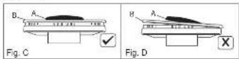
After cleaning, make sure head "C" and covers "A" and "B" are properly placed on their seat as figure "C" and not off-center as in figure "D".
TROUBLE·SHOOTING GUIDE
ABNORMAL OPERATION
Any of the following are considered to be abnormal operation and may require servicing:
Yellow tipping of the hob burner flame.
Sooting up of cooking utensils.
Burners not igniting properly.
Burners failing to remain alight
Burners extinguished by cupboard doors.
Gas valves, which are difficult to turn.
In case the appliance fails to operate correctly, call the number on the data label located on the front of this manual.
BEFORE YOU CALL THE SERVICE MAN
A review of the following may save you a service call and if not it may help you explain the malfunction to the serviceman. Read the operating instructions carefully. Be sure you know how to opera the appliance. If base of cooking utensils show signs of carbon (sool) deposit, this could indicate an incorrect burner flame. Please contact local service number (refer to the data label on the front of this instruction manual).
THE BURNER DOES NOT LIGHT
- Check to ensure Hotplate cord is plugged into outlet. Check for a blown fuse or tripped circuit breaker.
- Hotplate not properly grounded or polarized. This can effect ignition on spark ignition models.
• Check for power wallage
• Gas supply not connected or not turned on.
- A pan is sitting on the burner grate. This may partially block the free air flow needed for combustion. Remove the pan and try again.
• Burners not adjusted properly.
- Food clogging burners or burner assembly misaligned. Make sure that burner ports on side of burner are not clogged. Make sure that burners are positioned correctly.
WHEN YOU CALL FOR SERVICE
When you call for service or order parts for your Hotplate be sure to give:
1.MODEL
2.SERIAL NUMBER
3.COLOUR
4.PART NAME and/or description of problem
5.YOUR FULL NAME, ADDRESS, and HOME TELEPHONE NUMBER and BUSINESS TELEPHONE NUMBER IF APPROPRIATE.
HOT PLATES
INSTALLATION AND USER INSTRUCTIONS
natural_image
Simple diagram with a square containing six dots and plus signs, enclosed in a rounded rectangle (no text or symbols)Electrolux
GALLERY
Congratulations on the purchase of your new Hot Plate
which is built to give you years of satisfactory service and pleasure when properly cared for and used.
Producing an efficient Hotplate that conserves energy required a considerable investment of time, effort and money.
Your Hotplate is engineered to surpass all performance and safety requirements. However, safety is also YOUR responsibility through proper use and care.
With this in mind, it is important that you read this booklet. Acquaint yourself with the features and follow the use and care suggestions carefully for complete satisfaction.
Remember: only authorised personnel must make the necessary gas and electrical connections.
Be sure you know the correct model and serial model of your Hotplate. The data plate is sealed on the outside of the lower case of your Hotplate.
RECORD HERE FOR EASY REFERENCE
Model
Colour Serial Number.
Installation Date
Dealer's Name and Address
ENVIRONMENTAL WARNING
Waste packaging
Do not throw the packaging of your appliance into the dustbin, but pick out the different materials (e.g. foil, paperboard, polystyrene) according to the local rules for recycling.
This appliance must only be used for the purpose of domestic cooking.
INDEX
INSTALLATION INSTRUCTIONS....psg. 3 - 6
SERVICE INSTRUCTIONS. pag. 7-8
USERS INSTRUCTIONS ......pq. 10 - 12
WARNING
* This appliance is not intended for use by young children or infant persons without supervision.
* Young children should be supervised to ensure that they do not play with the appliance.
WHERE THIS APPLIANCE IS INSTALLED IN MARINE CRAFT OR IN CARAVANS, IT SHALL NOT BE USED AS A SPACE HEATER.
USERS INSTRUCTIONS
as they are inherently unstable.
To save gas, always position pans centrally over the burners and adjust the flames so that they do not lick up the sides of the panand only the base is heated. Always put lids on a saucepans and boil only the amount of liquid you use. When the liquid has boiled adjust the setting to maintain a simmer.
Do not light the burner until the pan is in position and turn off the burner before removing the pan. In hard water areas, descale kettles regularly. For safety, keep saucepan handles turned to a safe position so they are out of reach of small children and cannot be accidentally knocked.
WARNING
It is not recommended to press push button for ignition if all the burners are not located in the proper positions. The burner heads, burner skirts and pan supports are removable for better cleaning: Always ensure that the burner skirts and heads are replaced correctly so that the burners function safely and correctly. During the use of the appliance pay attention that water or any liquid does not enter into the appliance through the holes of the burners or around the rods of the valves or the push button electronic lighter.
Water and other liquids will produce dangerous short-circuits and can seriously damage the working of the Hotplate. The base of the Hotplate casing will become hot in use and must not be touched through a drawer or cupboard openings.
CLEANING
Cleaning should only be carried out when the appliance is COOL and is SWITCHED OFF.
Always clean off spillage as quickly as possible to prevent burning which will make removal more difficult. Do not use harsh abrasive rags or products; they can seriously damage the appliance. For Hotplate top and enamelled pan supports use a wet cloth with liquid detergent.
FOR YOUR SAFETY
Where this appliance is installed in marine craft or in caravans, it shall not be used as a space heater.
Do not spray aerosols in the vicinity of this appliance while it is in operation.
1) If you smell gas:
— open the windows
— don't touch electrical switches
— extinguish any open flame
— never use a flame to locate such a leak, use soapy water
only
— contact authorised technician.
2) Keep children away from the appliance: they can suffer serious personal harm by touching the hot parts of the appliance and the pans.
3) Don't store items that are attractive to children above or near the appliance.
4) Do not store flammable products near the burners such as fabric, cartons or plastic boxes and especially aerosol containers.
5) In order to avoid any unintentional fall down, pan handles should be turned to the back of the cooker, not out to the room or over adjacent burners.
6) When cooking, don't wear clothes with flammable sleeves.
USERS INSTRUCTIONS

A-Bumer cap B-Lighting plug C-Triple flame cap D-Flame spreader
Dual triple flame version

no gas flow

maximum gas flow from central burner

minimum gas flow from central burner

maximum gas flow from outer and central burners simultaneously

minimum gas flow from outer and central burners simultaneously
To light the burner, turn the appropriate knob anticlockwise to the low position (marked with a small flame symbol 📄) and depress the ignition button and release. If burner does not ignite repeat the procedure. To adjust the burner to the full-on position, turn the control knob clockwise to the appropriate setting (marked with a large flame symbol 📄).
Where this appliance is installed in marine craft or in caravans, it shall NOT be used as a space heater ^1 .
To turn the burner OFF, turn the control knob clockwise to the OFF selling (marked with a dot ●).
APPLIANCES WITH SAFETY VALVE
Follow the same procedure described above to ignite the burners. In this case, however, once you have turned the knob to the open setting, hold it pressed in for 10 seconds. If for any reason the burner flame goes out, the safety valve automatically shuts off the gas supply to the burner in question.
It is recommended that pans suitable to the size of the burner should be used as follows:
| Burner | minimum diameter | maximum diameter |
| Large (rapid) | 180mm | 230mm |
| Medium (semi-rapid) | 120mm | 200mm |
| Smell (Auxiliary) | 80mm | 160mm |
| Triple Flame | 220mm | 260mm |
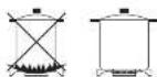
Always use pans with all flat base diameter, which are well balanced and stable in use, a pan which overhangs the hotplate should not be used. Avoid using old, misshapen pans, or pans which are unstable when placed on a flat surface. Do not use "split pans"
INSTALLATIONS INSTRUCTIONS
GAS HOT PLATE
IMPORTANT NOTICE TO THE INSTALLER
"SAFETY WARNINGS ABOUT INSTALLATION"
The cooker MUST be installed and serviced by a qualified technician. A Certificate of Compliance MUST be supplied to be kept by the customer.
The packing materials MUST be removed before you install the cooker.
You MUST follow the installation instructions in this book. The surrounding kitchen cabinets MUST be able to withstand 85°C. The pipes used for installation MUST have sufficient loops so the cooker can be moved for service.
The vents, openings and air spaces MUST not be blocked The anti-bit bracket MUST be installed to avoid accidental tipping. You MUST not pull the cooker by the door handles or rear splash panel
The cooker MUST be checked every five years.
GAS CONNECTION
The appliance shall be installed by an authorized person in accordance with the manufacturer's installation instructions, relevant local fitting regulations, municipal building regulations, the A35501 (A3601) - Gas Installation. For gas burning appliances and equipment and other relevant statutory code band regulations. If you have some doubts, please contact the authorities for confirmation concerning the characteristics of the gas and electricity output.
The appliance is generally preset for natural gas (so no other adjustment is necessary) and equipped with a regulator with pressure test point. Ensure that all foreign matter has been cleared from the gas supply line and also purge all air from the gas system. Connect to regulator, lighten and check the installation to ensure
no gas leaks occur. Check gas pressure, a duplicate label is supplied and adhered to the front of this instruction manual, note the correct setting from the data plate sealed on the lower side of the case. 5 burner models: "burner pressure is to be set at 1 kpa with middle front and right front burners operating at full rate. Apply a manometer to the test nipple and reset the regulator if necessary.
Do not forget to replace the test nipple screw and to leave the instructions book with the user.
For the adjustments to TLP or U-LPG gas, please operate as specified in the paragraph GAS CONVERSION AND ADJUSTMENT (Page. 8).
Important: several parts are protected with a special anti-scratch film. Please remove it before use.
This appliance from the factory suitable for NATURAL gas but, if necessary, can be adjusted for U-LPG or TLP gas by a competent licensed person.
This appliance is of type "X" with regard to protection against over heating of surrounding surfaces.
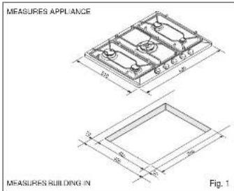
5 BURNER UNIT
DIMENSIONS
| Overall Height above work surface | 45 mm |
| Width | 680 mm |
| Depth | 510 mm |
| Minimum space above hotplate | 600 mm |
CONNECTIONS
| Gas....RC 1/2 (1/2" B.S.P.) |
| Electric....1 mm ^2 3 core cable (3 amp fuse required) |
| Should conform to local gas authority requirements. |
| Also refer to rangehood manufacturers recommendations. |
INSTALLATIONS INSTRUCTIONS
POSITIONING
The Hotplate unit should be placed in a position free from draughts and with good light. The unit must not be fitted closer than 30 mm on the left hand side to non-combustible cupboards or wall. No shelf or overhang should be closer than 500 mm (23 mm) above the unit unless protected by a suitable tireproof material. In addition, there should be a clearance of at least 110 mm (4 mm) between the back wall and the back edge of the unit.
Protected Area: Any combustible surface within this area, except upward facing surfaces, must be protected by an approved noncombustible material.
The protected area extends:
(a) above the prohibited area by 150 mm vertically for the full width and depth of the cooking surface area and; (b) horizontally beyond the edge of the cooking surface area to a point 200 mm from any burner, as shown, in the plan view, and to a height of 450 mm above the top of the burner.
VENTILATION
Ventilation must be in accordance with AS5601:AG601-Gas Installations. In general, the appliance should have adequate ventilation for complete combustion of gas, proper fluing and to maintain temperature of immediate surroundings within sale limits.

INSTALLATION
This Hotplate unit is suitable for installation into a work surface which has a minimum depth of 600 mm (23 in) and which is resistant to temperature up to 90°C). Prepare a cut-out in the work top with dimensions 450 mm (18 in) back to front and 560 mm (21 in) side to side. The cut-out should not be less than 45 mm (1 in) from the rear edge of the work surface.
When the HP is installed there must be a minimum clearance of 110 mm (4 mm in) between both the left hand edge and the rear edge of the Hotplate and any adjacent walls or cabinets (See Fig. 1).
USER INSTRUCTIONS
| Gas Type | kPa | Jet mm | Burners | Power MJ |
| Natural gas | 1.00 | 1.14 | Semi quick | 6.5 |
| 0.85 | Auxiliary | 8.7 | ||
| 1.50 | Quick | 11.5 | ||
| 0.78/1.75 | Triple Crown | 17.3 | ||
| Universal LPG | 2.75 | 0.70 | Semi quick | 6.4 |
| 0.55 | Auxiliary | 4.0 | ||
| 0.95 | Quick | 11.9 | ||
| 0.04/1.05 | Triple Crown | 17.3 |

USING THE GAS HOT PLATE
NOTE: This hotplate is for domestic use only.
1.Hob
2.Medium semi-rapid bumer
-
Small auxiliary burner
-
Large rapid burner
5.Burner control knobs
6.Triple flame bumer
Instructions for use
The hob control knobs
The symbols on the control knobs mean the following:
• no gas flow
A maximum gas flow
• Healthcare, Global
minimum gas flow
All operating positions must be set between the maximum and minimum flow settings, and never between the maximum setting and the closed position.
※ (symbol present on version with lighting
integrated in the control knob.)
SERVICE INSTRUCTIONS
LPG conversion instruction
Changing the nozzles
1) Turn off gas supply to appliance. 2) Disconnect appliance from electrical power (if applicable).
3) Remove the trivets.
4) Remove the burner caps and flame spreaders from the burners.
5) Use a size 7 tube spanners to unscrew and remove the nozzles, replacing them with those corresponding to the type of gas to be used (see table).
6) Reassemble the parts, reversing the operations described above.
Changing the nozzles for burner triple flame
1) Remove the trivets.
2) Remove the burner caps and flame spreaders from the burners. 3) Unscrew the screws V and remove the plate P.
4) With a size 7 tube spanners the nozzles A of the external burner and the central nozzle B.


A) Remove the appliance NG regulator and replace with test point adaptor.
Ei Turn on gas & check for leaks.
C) Check and adjust the test point pressure according to the procedure in the installation instructions.
D) Light all burners and operate at maximum.
E) Then replace the data plate and also remove NG gas label (if attached) and replace with LPG label
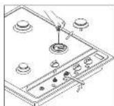
Setting the minimum level
1) Light the burner as already described.
2) Turn the tap to the minimum flame position.
3i Remove the control knobs.
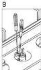
4) Use a thin straight screwdriver to turn the by-pass pin located next to the tap shaft (see fig. A). If you are converting from natural gas to LPG, turn the by-pass pin fully clockwise.
The result should be a small, homogeneous flame which is uniform around the entire burner ring. For the Dual Triple Flame version see fig. B, by pass 1 central burner, by pass 2 both burners.
5) Finally, check that the burner does not go out when the tap is turned quickly from the maximum to the minimum position.

INSTALLATIONS INSTRUCTIONS
Insertion and fixing
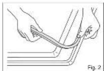
Before inserting the hob in the installation opening, place the special gasket around the bottom edge of the hob. It is important to fix this gasket evenly, without gaps or overlapping, to prevent liquid from seeping underneath the hob.
1) Remove the pan stands and the burner caps and turn the hob upside down. taking care not to damage the ignition plugs and the thermocouples.
2) Place the gasket around the bottom edge of the hob as shown in the illustration on the right fig.2).
3) Place the hob in the installation opening and push it down so that the hob is resting firmly on the cabinet, as shown in the illustration (fig.3).
The side springs will hold it in place.
4) Remove with a cutter the gasket in excess from the edges of the hcb (fig 4).
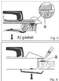
When the appliance is installed so that the base can be touched, we recommend fitting a protecting shield. This shield must project at least 20mm from the lower part of the appliance and be capable of withstanding the appliance temperatures.

INSTALLATION INSTRUCTIONS
GAS CONNECTION
The gas inlet is situated at the rear of the appliance, 250mm from the right-hand side and 58mm from the rear of the cooktop. It necessary, cut a suitable hole in the back of the cabinet for the entry of the gas supply and electric cable.
IT IS RECOMMENDED THAT A SERVICE TAP AND UNION BE FITTED ADJACENT TO THE APPLIANCE INLET TO FACILITATE FUTURE SERVICING. ENSURE THE REGULATOR SUPPLIED (FOR NATURAL GAS) IS FITTED BEFORE APPLIANCE.
VERY IMPORTANT FOR THE INSTALLER
Do not attempt to turn or stress the threaded elbow of the manifold: you risk damage to this part of the gas appliance which may void the manufacturers warranty.
It is not recommended that a hose assembly is used unless authorised by the local authority.
BEFORE LEAVING
Check all connections for gas leaks with soap and water. DO NOT use a naked flame for detecting leaks. Ignite all burners to ensure correct operation of gas valves, burners and ignition. Turn gas taps to low flame position and observe stability of the flame. When satisfied with the hotplate, please instruct the user on the correct method of operation. In case the appliance fails to operate correctly after all checks have been carried out, refer to the authorised service provider in your area.
ELECTRICAL CONNECTION
IMPORTANT
This hotplate is supplied with a plug & cord, simply plug into a 3 pin household socket outlet which is properly earthed. In order to avoid hazard, any electrical work performed on this equipment or its associated wiring, should only be done
by persons authorised by the supplier or similarly qualified persons.
The wires in the mains lead are coloured in accordance with the following code:
GREEN & YELLOW....EARTH BLUE....NEUTRAL
If the supply cord is damaged, it must be replaced by the manufacturer or its service agent or similarly qualified person in order to avoid a hazard.
WARNING: THIS APPLIANCE MUST BE EARTHED. The flexible mains lead and plug must not be in contact with hot surfaces.

SERVICE INSTRUCTIONS
SERVICING FOR HOT PLATES
All service should be carried out be a authorised service technician only.
WARNINGS
Before performing any repair or operation, switch the appliance off and close the gas tap.
The manufacturer declines all responsibility for any damage to persons, animals or things caused by failure to observe the rules indicated above. In case it is necessary to repair or replace the inside components, act as follows:
DISASSEMBLY OF WORK-TOF
- disconnect the electrical supply cable
- disconnect the gas supply tube
- remove the pot supports
- remove burner caps and flame-spreaders
- remove the knobs from the face-panel
- disassemble the work-top from the cabinet unscrewing screws blocking looking bridle.
Stocking locking brides.
Remove the acc from the top.
A) On the lower plate of the hob, on the outside there are some visible screws fixing the burners and the gas manifolds to the chassis.
Once these screws or screw nuts are unscrewed, it is possible to replace the components inside the hob.

B) The hob is fixed in its upper part to the burners by means of some visible screws. If these screws and the nut blocking the taps to the hob are screwed, it is possible to open the appliance and to reach the inside components (see picture below).
GAS CONVERSION AND ADJUSTMENT
When used with natural gas all burners have been preset at our factory and turner adjustment should not be necessary. Conversion kits to other gases are available from the place of purchase. Do not attempt to lift the conversion kit yourself. Conversion to U-LPG should only be carried out by an authorized technician.


- ABNORMAL OPERATION
- BEFORE YOU CALL THE SERVICE MAN
- THE BURNER DOES NOT LIGHT
- WHEN YOU CALL FOR SERVICE
- HOT PLATES
- INSTALLATION AND USER INSTRUCTIONS
- Congratulations on the purchase of your new Hot Plate
- RECORD HERE FOR EASY REFERENCE
- ENVIRONMENTAL WARNING
- Waste packaging
- INDEX
- WARNING
- USERS INSTRUCTIONS
- CLEANING
- FOR YOUR SAFETY
- Dual triple flame version
- APPLIANCES WITH SAFETY VALVE
- INSTALLATIONS INSTRUCTIONS
- GAS HOT PLATE
- IMPORTANT NOTICE TO THE INSTALLER
- GAS CONNECTION
- BURNER UNIT
- POSITIONING
- VENTILATION
- INSTALLATION
- USER INSTRUCTIONS
- USING THE GAS HOT PLATE
- 1.Hob
- Instructions for use
- The hob control knobs
- SERVICE INSTRUCTIONS
- LPG conversion instruction
- Setting the minimum level
- Insertion and fixing
- INSTALLATION INSTRUCTIONS
- VERY IMPORTANT FOR THE INSTALLER
- BEFORE LEAVING
- ELECTRICAL CONNECTION
- IMPORTANT
- SERVICING FOR HOT PLATES
- WARNINGS
- DISASSEMBLY OF WORK-TOF
- GAS CONVERSION AND ADJUSTMENT
Brand : ELECTROLUX
Model : EHG 77
Category : Hot plate