ERM3707 - Fridge ELECTROLUX - Free user manual and instructions
Find the device manual for free ERM3707 ELECTROLUX in PDF.

User questions about ERM3707 ELECTROLUX
0 question about this device. Answer the ones you know or ask your own.
Ask a new question about this device
Download the instructions for your Fridge in PDF format for free! Find your manual ERM3707 - ELECTROLUX and take your electronic device back in hand. On this page are published all the documents necessary for the use of your device. ERM3707 by ELECTROLUX.
USER MANUAL ERM3707 ELECTROLUX
text_image
connection kit installation manual e:line modular refrigerationConnection kit
This connection kit is designed for use on the following top mount, bottom mount and single door refrigerators and freezers whose total body height is 1720 mm.
The model numbers and overall dimensions of individual products are:
| max door height | cabinet height | total height | door width | cabinet width | total depth | cabinet depth | depth door open | |
| model description (H) (H1) (H2) (W) (W1) (D) (D1) (D2) | ||||||||
| ETM5207SA-R 520 lt Top Mount, RH Door 1720 | 1702 | 1720 800 | 790 | 735 | 612 | 1450 | ||
| ETM5207SA-L 520 lt Top Mount, LH Door 1720 | 1702 | 1720 800 | 790 | 735 | 612 | 1450 | ||
| ETM4407SA-R 440 lt Top Mount, RH Door 1720 | 1702 | 1720 700 | 690 | 735 | 612 | 1350 | ||
| ETM4407SA-L 440 lt Top Mount, LH Door 1720 | 1702 | 1720 700 | 690 | 735 | 612 | 1350 | ||
| EBM5107SA-R 510 lt Bottom Mount, RH Door 1720 | 1702 | 1720 800 | 790 | 735 | 612 | 1450 | ||
| EBM5107SA-L 510 lt Bottom Mount, LH Door | 1720 | 1702 | 1720 800 | 790 | 735 | 612 | 1450 | |
| EBM4307SA-R 430 lt Bottom Mount, RH Door 1720 | 1702 | 1720 700 | 690 | 735 | 612 | 1350 | ||
| EBM4307SA-L 430 lt Bottom Mount, LH Door | 1720 | 1702 | 1720 700 | 690 | 735 | 612 | 1350 | |
| ERM3707SA-R 370lt Single Door Refrigerator, RH | 1720 | 1702 | 1720 605 | 595 | 672 | 550 | 1193 | |
| EFM3007SA-L 300lt Single Door Freezer, LH | 1720 | 1702 | 1720 605 | 595 | 673 | 550 | 1193 | |
All measurements are in millimetres
Single cabinet dimensions
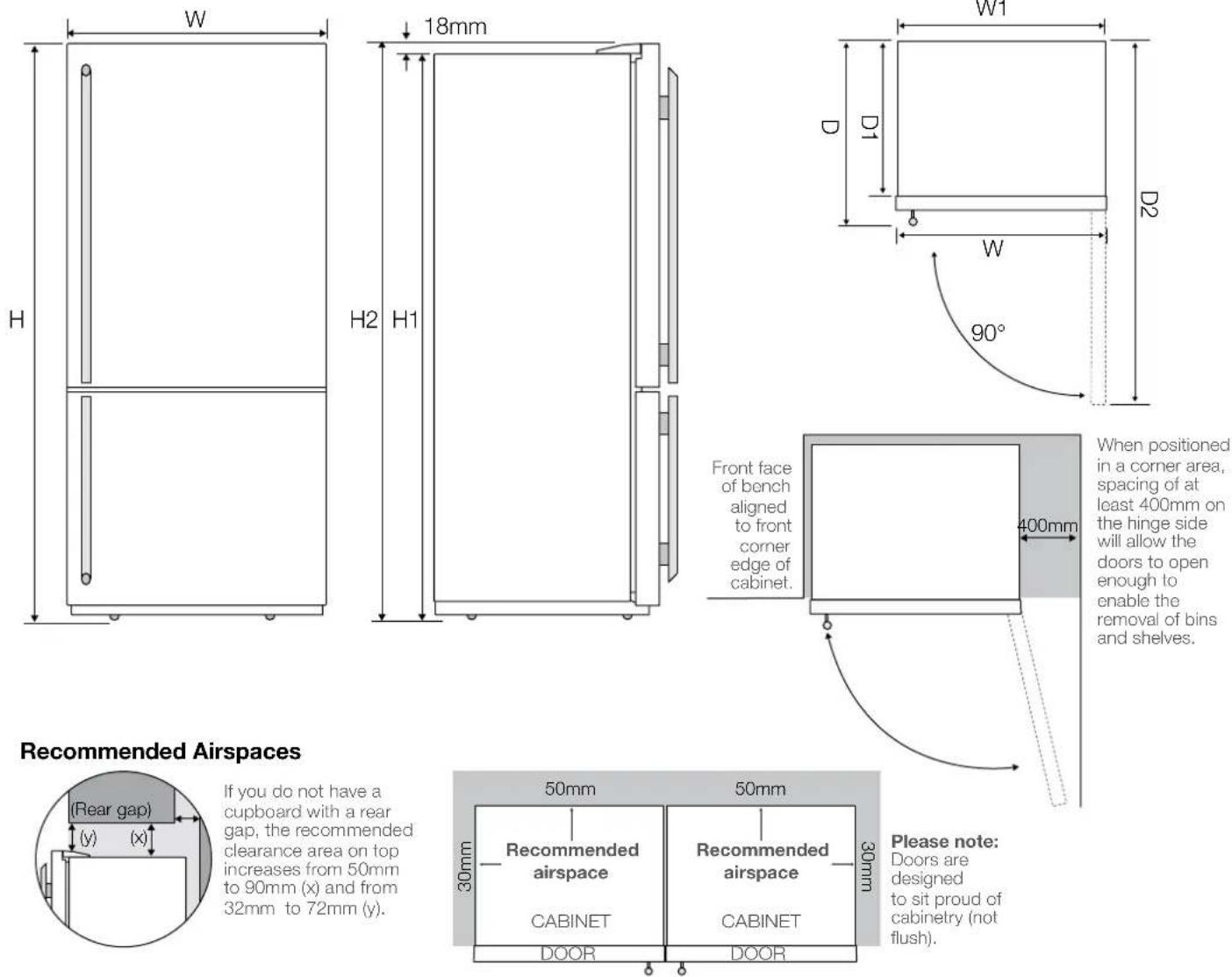
If you do not have a cupboard with a rear gap, the recommended clearance area on top increases from 50mm to 90mm (x) and from 32mm to 72mm (y).
Please note: Doors are designed to sit proud of cabinetry (not flush).
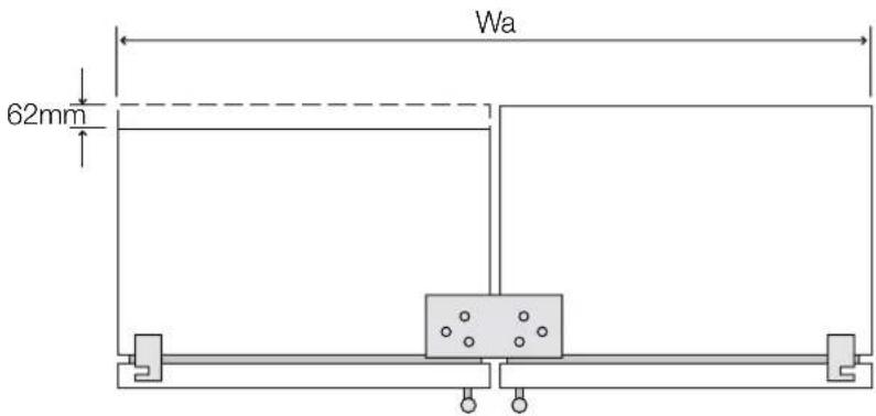
Joined dimensions
Note:
It is possible to join together cabinets of different depth. In such a case one cabinet will be 62 mm shorter at the back.
text_image
62mm Wa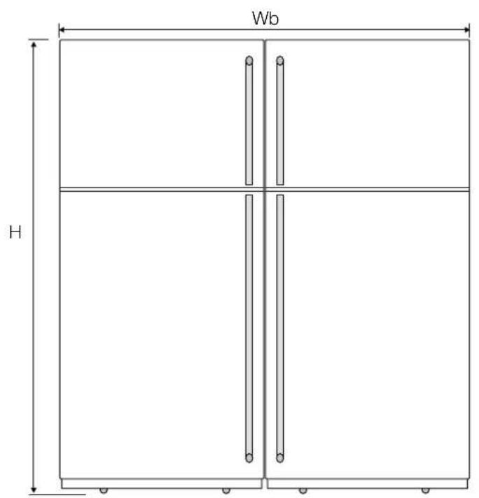
text_image
Wb H
text_image
D D1 H1Joined cabinet dimensions:
| individual cabinet widths(W1)model 1 model 2 (H1) (H) (Wa) (Wb) (D) (D1) | cabinet height | max door height | joined cabinet width | joined door width | max total depth | max cabinet depth |
| 790 790 1702 1720 1600 1612 735 612 | ||||||
| 790 690 1702 1720 1500 1512 735 612 | ||||||
| 790 595 1702 1720 1405 1417 735 612 | ||||||
| 690 690 1702 1720 1400 1412 735 612 | ||||||
| 690 595 1702 1720 1305 1317 735 612 | ||||||
| 595 595 1702 1720 1210 1222 673 550 |
All measurements are in millimetres
Before you begin
- Thoroughly inspect cabinets for any signs of damage before commencing installation.
- If any damage is identified please contact Electrolux Service.
- Check refrigerator recess dimensions and ensure that they provide at least the minimum clearance at the back, side and top as recommended on page 2.
- The floor where the refrigerator is to be placed must be level otherwise you will not be able to install your refrigerator properly.
- Ensure that the floor and surrounding cupboards are adequately protected from damage during unpacking and throughout the installation process.
- Ensure that two adequate and accessible power points are installed inside the refrigerator recess before installing and connecting your appliances. These power points should also be readily accessible after fridge installation is completed.
- Do not use extension leads or power board or double adapter under any circumstances as it may lead to electric shock and / or fire. Seek assistance of a licensed electrician if required.
- Unpack the connection kit and check for completeness by referring to the "Connection kit package content" section.
Note:
Due to size and weight of the cabinets as well as complexity of the task ensure that installation is attempted with at least two able-bodied persons. You are strongly urged to consider hiring Electrolux Service to do the installation.
Connection kit package contents
| description qty | ||
 | Lower front bracket assembly | 1 |
 | Top bracket 1 | |
 | Top bracket screw 6 | |
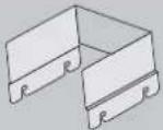 | Rear clamp 1 | |
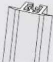 | Centre cover assembly | 1 |
 | Centre cover top screw | 2 |
 | Disposable protective foam | 2 |
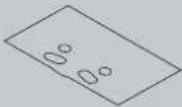 | Protective cardboard – provisional top bracket assembly | 1 |
 | Rear adjustable roller 4 | |
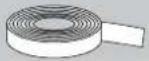 | Tape 1 | |
Installation procedure
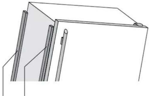
- Tape disposable protective foam to the door and rear edge of the cabinet on one of the products before commencing any work and attempting to bring the cabinets closer together. Foam should be applied to the front and rear edge of the cabinet.
natural_image
Pure technical line drawing of a mechanical assembly without any text, numbers, or symbolsSecure protective foam to the side of the cabinet using tape supplied in the connection kit. Foam should be secured on the handle side of the cabinet.
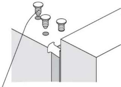
- Your appliance is delivered with three hole plugs filling the screw holes for the top bracket. Those holes are located on the top of the cabinet, opposite from the door hinge. Carefully remove hole plugs using a small screwdriver or a knife. Care must be taken to avoid damage to the refrigerator/freezer when removing the plugs.
natural_image
Diagram showing a mechanical joint with four bolts and a hand holding a tool, no text or symbols presentCarefully remove hole plugs from holes to allow fitment of the top bracket.
- Provisionally join the two cabinets at the top with the top bracket and screws, placing the protective cardboard between the bracket and cabinets. This will provide adequate protection of the cabinets against scratching while they are only temporarily joined at the top and manipulated for installation purposes.

natural_image
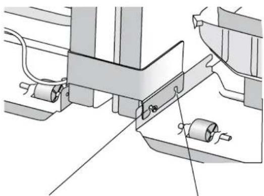
Technical line drawing of a mechanical assembly with mounting brackets and a central component (no text or symbols)- Provisionally join the two cabinets together at the back, near the compressor, using the rear clamp. Loosen the fasteners connecting the compressor mounting plate to the cabinet and engage rear clamp, leave the fasteners partially loose at this stage.

caution
Do not remove compressor mounting fasteners as this may cause the appliance to loose stability.
natural_image
Technical diagram of a mechanical assembly with rollers and brackets (no text or symbols)Leave the compressor mounting plate fastener partially loose after engaging the rear bracket.
This hole on the rear bracket is used only when two cabinets of different depths (D1) are being joined together (i.e. 690 + 595 model or 790 + 595 model).
natural_image
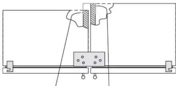
Pure mechanical diagram showing a lever and pivot mechanism without any text, numbers, or symbolsTwo cabinets of different depths joined at the back with rear clamp. Notice that compressor mounting plate fasteners are in different location on the rear clamp.
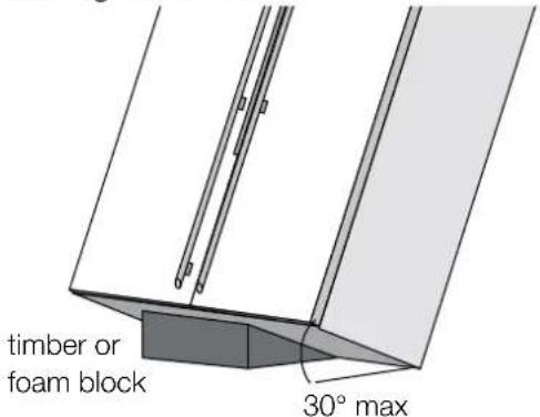
- Join the two cabinets at the front lower end using the bottom bracket. To enable this, have an assistant tilt the two provisionally joined cabinets approximately 30 degrees. Before performing any work underneath the cabinets ensure that assistant has full grip of the cabinets and that you can clearly and concisely communicate with your assistant. Ensure that you use timber, foam or similar items to support and secure the tilted cabinets. Care must be taken to avoid damage of cabinets, compressor, copper tubing and floor. Use masonite or similar to protect the floor from scratching before the cabinets are tilted.

tips and information
Ensure enough distance away from island benches when performing this action
text_image
timber or foam block 30° maxTilt the cabinet back by no more then 30 degrees. This will enable adequate access to the front feet in order to install lower bracket. Ensure that assistant has firm grip of the cabinets before continuing. Use chocks or other means of firmly supporting the cabinets before attempting further installation work. The cabinets can be best tilted by having assistant pull and support the appliances from the back.
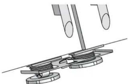
- With the cabinet tilted back loosen the two large adjusting roller nuts to allow for assembly of the bottom bracket. Secure the bottom bracket with the large adjusting nuts, ensure that both rollers are adjusted to approximately the same height to facilitate easier cabinet leveling at a later stage.
natural_image
Mechanical assembly diagram showing a tool interacting with a mechanical component (no text or symbols visible)- With the two cabinets provisionally connected level both units using adjustable rollers as per recommendations in your owner's manual. Gently push the assembly back into the wall cavity and check for alignment and level. If necessary, pull the cabinets out again and adjust, repeat the procedure until satisfied with level and alignment.

tips and information
If the cabinets still are not level after adjusting front rollers, follow the steps below to fit and adjust rear adjustable rollers. This must be done before securing the two cabinets together.
Notes:
- This is a two man operation and should be done before the two cabinets are connected with the connection kit.
- Rear adjustable rollers are required on cabinets and can be installed on 430L, 440L, 510L and 520L cabinets only.
- Tilt the cabinet forward by approximately 30° ensuring stability in tilted position.
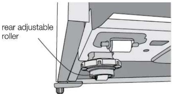
- Insert the rear adjustable rollers into the existing slots in the base plate at the rear of the refrigerator. Push them until they click into position.
- Remove the auxiliary drain pan and discard before installing the rear adjustable rollers.
Note: Auxiliary drain pan is present on 500L models only
text_image
rear adjustable roller- Lower both cabinets gently ensuring the appliance rests on both rear adjustable rollers.
-
Wind the rear adjustable rollers up or down along with the front adjustable rollers to raise or lower the cabinet and match the height with respect to the adjacent cabinet.
-
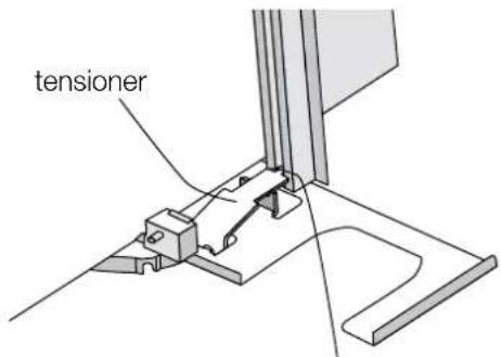
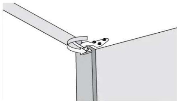
When satisfied with levelling and alignment fully secure rear clamp, remove the top bracket and protective cardboard and the front disposable protective foam, insert the center cover by engaging it into the tensioner on the bottom bracket. Gently push the centre cover between the two cabinets, place the top bracket back on top of the two cabinets and ensure that it is fully engaged with the centre cover. Fully secure the top bracket with six fasteners.
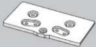
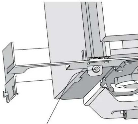
text_image
tensionerEngage the center cover piece into the tensioner of the bottom bracket. To facilitate this loosen the tensioner if required.
Adjusting door alignment
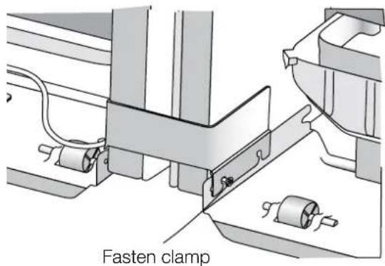
text_image
Fasten clamp- Adjust tension on centre cover for flush mounting with cabinets.
natural_image
Technical line drawing of a mechanical assembly with no visible text or symbolsTension on the center cover can be adjusted with the screw on the bottom bracket
- Secure the centre cover piece to the top bracket with the single, self tapping fastener.
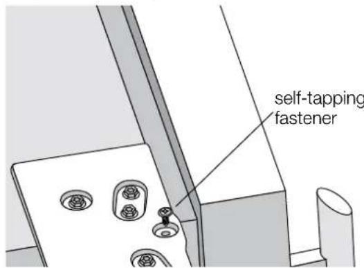
text_image
self-tapping fastener-
Push the appliances back into the wall cavity, ensure adequate clearance is maintained to the back and on each side of the cabinets (see page 2).
-
Wind the stability foot on both cabinets down until they just touch the hard floor surface.
To complete installation of your joined appliances it may be necessary to slightly adjust door alignment on the individual appliance. This process is illustrated in the following section
- With the door open remove the hinge cover by simultaneously pulling the cover away and up from the hinge. This action will release the clip that is retaining the cover to the hinge.
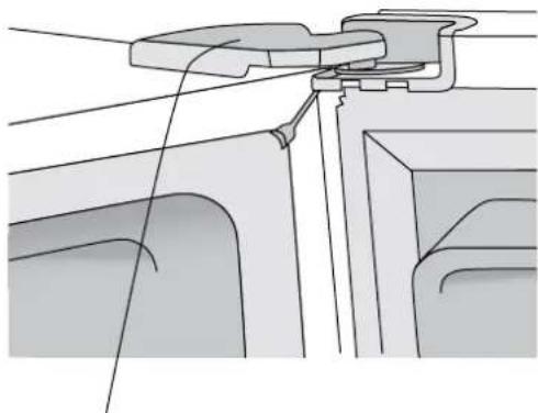
natural_image
Technical line drawing of a mechanical assembly with no visible text or symbolsSmall plastic clip is located here. With the door open pull the cover outward while simultaneously pulling up in order to release the hinge cover.
- Slightly loosen the three screws retaining the hinge to the cabinet. This will allow for slight movement of the cabinet door. Have the assistant hold the door in desired position and fully secure top hinge fasteners, inspect the alignment and if satisfied clip the hinge cover back onto the top hinge.
natural_image
Pure technical line drawing of a mechanical joint or bracket (no text or symbols)Loosening the top hinge fasteners will allow the top hinge to be slightly rotated thus adjusting the gap between doors.

caution
Hinge screw torque must be between 5-10nm to ensure doors are held securely.
Electrolux Home Products Australia
telephone: 1300 363 640
fax: 1800 350 067
email: customercare@electrolux.com.au
web: www.electrolux.com.au
The Thoughtful Design Innovator.
Do you remember the last time you opened a gift that made you say
"Oh! How did you know? That's exactly what I wanted!" That's the kind of feeling that the designers at Electrolux seek to evoke in everyone who chooses or uses one of our products. We devote time, knowledge, and a great deal of thought to anticipating and creating the kind of appliances that our customers really need and want.
This kind of thoughtful care means innovating with insight. Not design for design's sake, but design for the user's sake. For us, thoughtful design means making appliances easier to use and tasks more enjoyable to perform, freeing our customers to experience that ultimate 21st century luxury, ease of mind. Our aim is to make this ease of mind more available to more people in more parts of their everyday lives, all over the world. So when we say we're thinking of you, you know we mean just that.
Electrolux. Thinking of you.
Share more of our thinking at www.electrolux.com