95-8735B - Kit voiture Metra - Free user manual and instructions
Find the device manual for free 95-8735B Metra in PDF.

User questions about 95-8735B Metra
0 question about this device. Answer the ones you know or ask your own.
Ask a new question about this device
Download the instructions for your Kit voiture in PDF format for free! Find your manual 95-8735B - Metra and take your electronic device back in hand. On this page are published all the documents necessary for the use of your device. 95-8735B by Metra.
USER MANUAL 95-8735B Metra
natural_image
Interior view of a car dashboard with a digital display showing the right side (no visible text or symbols)Mercedes SL Class 2003-2008
Visit MetraOnline.com for more detailed information about the product and up-to-date vehicle specific applications
KIT FEATURES
• ISO DDIN radio provision
- Painted scratch resistant matte black
KIT COMPONENTS
• A) Radio trim panel • B) Radio brackets • C) (8) Flat-head ISO radio screws • D) (4) #8 x 3/8" Phillips screws
AE

natural_image
Line drawing of a rectangular frame with mounting holes (no text or symbols)[Non-Text]

C

TABLE OF CONTENTS
Dash Disassembly
-2003-2004 2
-2005-2008....3
Kit Assembly 4
WIRING & ANTENNA CONNECTIONS (sold separately)
Wiring Harness: See metraonline.com for
wiring harness options
Antenna Adapter: 40-EU10 (05-08) • 40-VW12 (03-04)
Steering Wheel Control Interface: • ASWC-1
TOOLS REQUIRED
- Panel removal tool • Phillips screwdriver
- 3mm Allen screwdriver • T-20 Torx screwdriver
• Cutting tool (03-04 models) • File (03-04 models)
Attention! Let the vehicle sit with the key out of the ignition for a few minutes before removing the factory radio. When testing the aftermarket equipment, ensure that all factory equipment is connected before cycling the key to ignition.
DASH DISASSEMBLY (2003-2004)
Attention! The factory radio must have the AM source selected before being removed from the vehicle.
Attention! A permanent modification to the center console trim bezel will be required. The factory radio will no longer be able to be reinstalled after this modification.
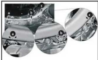
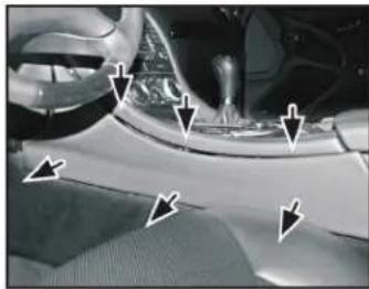
- Unclip and remove the left and right side panels from the center console. Remove (3) T-20 Torx screws from each side. (Figures A & B)
- Engage the parking brake then place the gear selector in neutral. Pull up on the gear selector boot just enough to allow the center console trim bezel to be removed. (Figure C)

natural_image
Close-up of a car's side panel with white arrows pointing to the edge (no text or symbols visible)(Figure A) (Figure D)
natural_image
Close-up of mechanical components with circular insets showing close-ups of parts (no visible text or symbols)(Figure B) (Figure E)

natural_image
Close-up of a white plastic tray with a circular button, mounted on a mechanical base (no visible text or symbols)(Figure C) (Figure F)
- Open the center console, then starting from the back, unclip and release the entire center console trim bezel which also wraps around the radio. Lift up just enough to access the connectors from underneath. Unplug all connectors, then remove the trim bezel. (Figure D)
- Remove (2) T-20 Torx screws securing the cup holders, then slide the cup holders out and remove them. (Figure E)
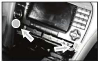
- Remove (4) T-20 Torx screws securing the radio. Slide the radio out, then unplug and remove the radio.
- Dash Modification: Cut the center console trim bezel to the left and right side of the bottom of the radio opening, slightly above the cup holders. These cuts will have to be perfect as they will be visible. Cut the trim bezel just enough to allow room for the kit. It may be best to leave a little extra, then file the rest. (Figure F)
Continue to Kit Assembly

natural_image
Close-up of a car's side panel showing dashboard and steering wheel (no text or symbols visible)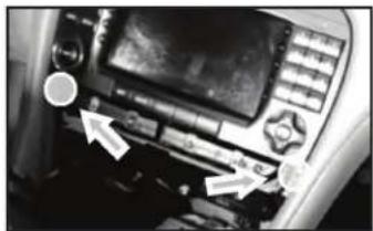
natural_image
Close-up of a mechanical device with control buttons and a display panel (no visible text or symbols)
text_image
103.5 FMDASH DISASSEMBLY (2005-2008)
Attention! The factory radio must have the AM source selected before being removed from the vehicle.
- Unclip and remove the left and right side panels from the center console. Remove (3) T-20 Torx screws from each side. (Figures A & B)
- Open both cup holders, then unsnap the trim covers from each cup holder. Push the cup holders back in, without their covers. (Figure C)
- Engage the parking brake then place the gear selector in neutral. Pull up on the gear selector boot just enough to allow the center console trim bezel to be removed. (Figure D)
natural_image
Close-up of a car's dashboard and steering wheel (no visible text or symbols)(Figure A)

natural_image
Close-up of mechanical components with circular insets showing close-ups of parts (no visible text or symbols)(Figure B)

natural_image
Mechanical component with two lenses and a handle, shown with directional arrows (no text or symbols)(Figure C)

natural_image
Close-up of a mechanical component with a cylindrical housing and a circular top component (no visible text or symbols)(Figure D)
- Open the center console, then starting from the back, undip and release the center console trim bezel just enough to access the connectors from underneath. Unplug all connectors, then remove the trim bezel. (Figure E)
Note: The trim bezel can also be rotated 90-degrees and left connected.
- Remove (2) T-20 Torx screws securing the cup holders, then slide the cup holders out and remove them. (Figure F)
- Press in on the (2) plastic clips below the radio to release the radio. Slide the radio out, then unplug and remove the radio. (Figure G)
Note: There are (2) metal tabs on top of the radio. After the radio has been released, the radio should drop down enough for these tabs to clear the dash.
Continue to Kit Assembly

natural_image
Close-up of a car headrest lever with a white arrow pointing to the left side (no visible text or symbols)(Figure E)
natural_image
Interior view of a vehicle's head and dashboard with control panel and buttons (no visible text or symbols)(Figure F)

text_image
Plastic Clips(Figure G)
KIT ASSEMBLY
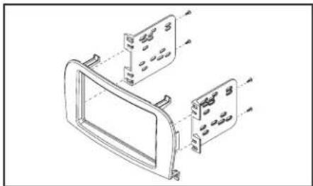
- Attach the radio brackets to the radio trim panel using (4) #8 x 3/8" Phillips screws supplied. (Figure A)
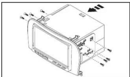
- Slide the radio into the completed assembly, and then secure it to the assembly. (Figure B)
Note: The radio mounting screws must be flush in the brackets so the radio assembly will fit into the dash opening. Screws have been provided in the event they were not provided with the aftermarket radio.
- Locate the factory wiring harness and antenna connector in the dash, and complete all necessary connections to the radio. Metra recommends using the proper mating adapter from Metra and/or AXXESS. Test the radio for proper operation.
- Reassemble the dash in reverse order of disassembly.
natural_image
Technical line drawing of a car front panel with mounting holes and mounting brackets (no text or symbols)(Figure A)
natural_image
Technical line drawing of a device casing with mounting holes and directional arrows indicating movement (no text or symbols)(Figure B)
If you are having difficulties with the installation of this product, contact our Tech Support line either by phone at 1-800-253-TECH, or email at techsupport@metra-autosound.com. Before doing so, look over the instruction booklet a second time and ensure that the installation was performed exactly as the instruction booklet is stated. Have the vehicle apart and ready to perform troubleshooting steps before contacting Metra/Axxess Tech Support.

KNOWLEDGE IS POWER
Enhance your installation and fabrication skills by enrolling in the most recognized and respected mobile electronics school in our industry. Log onto www.installerinstitute.com or call 800-354-6782 for more information and take steps toward a better tomorrow.

Metra recommends MECP certified technicians