Ax68R - Security Camera i3International - Free user manual and instructions
Find the device manual for free Ax68R i3International in PDF.

User questions about Ax68R i3International
0 question about this device. Answer the ones you know or ask your own.
Ask a new question about this device
Download the instructions for your Security Camera in PDF format for free! Find your manual Ax68R - i3International and take your electronic device back in hand. On this page are published all the documents necessary for the use of your device. Ax68R by i3International.
USER MANUAL Ax68R i3International
natural_image
Close-up of a spherical electronic device with 'i3 INTERNATIONAL' branding and a central speaker grille (no readable text beyond logo)Rev. 150505
CONTENTS
- Warnings and operation notes......3
- Unpacking......5
- Installation......6
- Mounting....10
- Connecting Ax68R/78R to the SRX-Pro Server......17
Ax68/Ax78R-series User Guide
COPYRIGHT © 2015 by i3 International, Inc. All rights reserved.
No part of this manual may be reproduced or transmitted in any form or by any means, electronic or mechanical, including but not limited to, photocopying, recording, or by any information storage or retrieval system, without the prior written permission of the copyright owner and the publisher.
Annexxus is a registered trademark of i3 International Inc.
Table of Contents
- Warnings and operation notes
- Unpacking
- Installation
- Mounting
- Connecting Ax68R/Ax78R to the SRX-Pro Server
Disclaimer
This quick start guide is provided as is, without warranty of any kind, expressed or implied, including but not limited to performance, merchantability, or fitness for any particular purpose. Neither i3 International Inc. nor its dealers or distributors shall be liable to any person or entity with respect to any liability, loss, or damage, caused or alleged to have been caused directly or indirectly by this information.
Furthermore, i3 International Inc. reserves the right to revise this publication, and to make changes to the content at any time, without notice.
FCC
This device complies with part 15 of the FCC Rules. Operation is subject to the following two conditions: (1) This device may not cause harmful interference, and (2) this device must accept any interference received, including interference that may cause undesired operation.
Address:
i3 International Inc.
780 Birchmount Road, Unit 16
Scarborough, ON M1K 5H4
Canada
Contact us:
Tech Support: 1.877.877.7241
Email. support@i3international.com
Web Site: www.i3international.com
1. Warnings and operation notes
Please read this guide carefully before you install the dome camera. Keep this guide for future reference.
Thank you for purchasing an i3 Ax68R/78R-series 360-degree camera.
If the system needs to be modified or repaired, contact a certified i3 International Dealer/Installer. When serviced by unauthorized technician, the system warranty will be voided. Should you have any problems or questions regarding our products, contact your local i3 International Dealer/Installer.
Camera's default IP address is 192.0.0.16
Camera's default Subnet mask address is 255.255.255.0.
Default camera User Name: i3admin and default Password: i3admin
1.1 Precautions
Installation and serving should be performed only by qualified and experienced technicians to conform to all local codes and to maintain your warranty.

WARNING! To reduce the risk of fire or electric shock, do not expose the product to rain or moisture.
When installing your Ax68R/Ax78R camera be sure to avoid:
• excessive heat, such as direct sunlight or heating appliances
• contaminants such as dust and smoke
• strong magnetic fields
- sources of powerful electromagnetic radiation such as radios or TV transmitters
• moisture and humidity
• areas with mechanical vibrations
• fluorescent lamps or objects that reflect light
• unstable light sources as this may cause flickering
- temperatures below -30^ Celsius or -22^ Fahrenheit and above 60^ Celsius or 140^ Fahrenheit.
1.2 Power Supply
Ax68R/Ax78R Power consumption requirement: 12V DC / PoE (IEEE 802.3af). Ensure the supplied voltage meets the power consumption requirements of this camera before powering the camera on. Incorrect voltage may cause irreparable damage to the video camera and will effectively void the camera warranty. PoE power is supported.
1.3 Cleaning
- For maximum optical clarity, the camera or lens must remain clean. Use a soft, dry cloth to remove finger prints and dust from the dome cover.
• Use a blower to remove dust from the lens. - Clean the body with a soft, dry cloth. If it is very dirty, use a cloth dampened with a small quantity of neutral detergent, then wipe dry.
- Do not use volatile solvents such as alcohol, benzene, or thinners, as they may damage the surface finish.
1.4 Servicing
To avoid electrical shock and to preserve the product warranty, DO NOT disassemble the camera. Refer servicing to qualified personnel only.
1.5 Routine Maintenance
- The dome bubble is an optical part. Use a soft and dry cloth to remove any fingerprints and dust.
- Clean the camera housing with a soft and dry cloth. For more stubborn marks, use a cloth dampened with a small quantity of neutral detergent, then wipe dry.
- CAUTION: Do not use volatile solvents such as alcohol, benzene or thinners, as they may damage the surface finish.
2. Unpacking
Ensure that the items received match those listed on the order form and the packing slip. In addition to this manual and a fully assembled camera, the dome camera packing box includes:
- Waterproof RJ45 connector (x1 package with 4 pcs).
Use to protect RJ45 cable connector from the elements. - User Manual and Annexus Finder CD x1
- Surface Mount template x1
- Plastic Anchor x4
- Round Head Screw (Tapping Type) x4
If any parts are missing or damaged, contact the dealer you purchased the camera from.
*Note: Based on installation location and surface type, supplied screws and anchors may not be adequate. Mounting hardware is site-specific and may need to be supplied by the installer.
2.1. Accessories (not to scale)
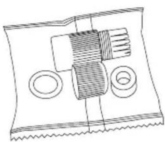
natural_image
Pure mechanical assembly diagram without any text, numbers, or symbols1

text_image
User Guide ACT2

text_image
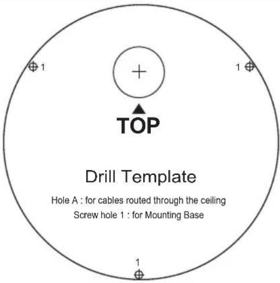
Drill Template Hole A : for cables routed through the ceiling Screw hole 1 : for Mounting Base3

4
5
Figure 1. Ax68/Ax78 Accessories
3. Installation
Ax68R/78R 360-degree Fisheye camera series is suitable for both indoor and outdoor installations in commercial and residential environment.
The Ax68R/78R camera is suitable for surface installation without added equipment.
Available accessories:
DB78BB - back box, for surface, goose-neck, and pendant installations DB60 - goose-neck bracket, used in conjunction with DB78BB in wall installations DB78TSM - angle mount bracket for surface installations
3.1 Disassembling the Camera
Before mounting the camera, follow these steps to disassemble the camera.

text_image
Step To ex the ca Lift th the sa S Us the ca to Lif Step To re- up theFigure 2. Disassembling Ax68R/Ax78R
Step 1
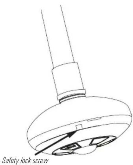
To expose the mounting screw holes, the camera cover must first be removed. Lift the safety lock screw cover to reveal the safety lock screw.
Safety Lock Screw (lift cover)
Step 2
Use a Phillips screwdriver to loosen the safety lock screw, then grip the camera cover and flex on one side, towards the center.
Lift UP to remove.
Step 3
To re-attach the camera cover, match up the safety lock screw with the screw hole on the camera body (10), then push straight down onto the camera cover to engage the clips. The camera cover will re-attach.
Step 4
Use a Phillips screwdriver to re-tighten the safety lock screw.
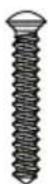
3.2 Dimensions & Parts Identification
text_image
52 mmFigure 3. Ax68/Ax78 Camera Side view, with camera cover attached

text_image
168 mm 1Figure 4. Ax68/Ax78 Camera, Top view, with camera cover attached. Lift the safety lock screw cover to reveal the safety lock screw (1). Use a Phillips screwdriver to loosen the lock screw, then grip the camera cover and flex on one side, towards the center. Lift UP to remove.

text_image
remove. 3 4 5 2Figure 5. Camera module with camera cover removed. Use a Phillips screwdriver to remove the SD card panel cover (2). to expose microSD card slot (3) and the RESET pin hole (4). Rubber gasket is provided for an airtight seal and moisture protection (5).

text_image
6 7 8 9 10 11 12 13Figure 6. Camera module with camera cover removed.
- Built-in speaker
- MicroSD card slot
Insert a micro SDHC card for backup/emergency recording and/or storage.
RESET pin hole
Use a sharp object to Press the Reset button, the camera will be rebooted.
-
Light sensor for day/night switching
-
IR LEDs x3
- Camera cover lock screw hole
- Mounting screw hole/slot x3
- Camera cover clips x3
- Built-in microphone
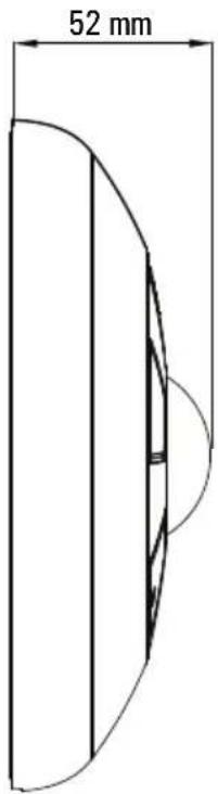
- DC12V Power connector
- RJ45 Network connector (PoE supported)
text_image
Technical diagram showing a car wheel with labeled connectors and numbered partsFigure 7. Ax68/Ax78 cabling.
i3-TRNG-CAMS-68R_78R.indd Rev. 150505
3.3 Surface Mounting

Important. Please Read:
- Use sealant at the locations shown on the mounting diagrams to maintain IP66 rating when installing outside.
- It is the installer's responsibility to ensure that the mounting surface is suitable for the chosen installation method.
- Based on installation location and surface type, supplied screws and anchors may not be adequate.
-
Mounting hardware is site-specific and may need to be supplied by the installer.
-
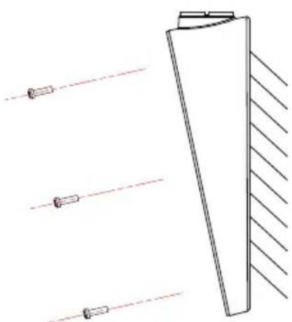
Use the Surface Mount Template to drill three (3) 6 mm (0.2") screw holes at the marked template positions on the mounting surface.
- Drill the cable opening at the marked template position.

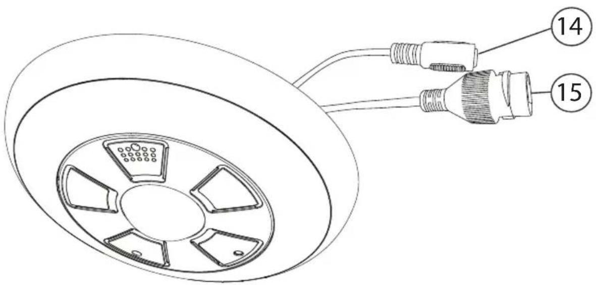
natural_image
Pure diagram of three vertical supports with diagonal hatching lines, no text or symbols presentFigure 9. Surface Mount - Steps 3-4.
text_image
Drill Template Hole A : for cables routed through the ceiling Screw hole 1 : for Mounting BaseFigure 8. Surface Mount Template
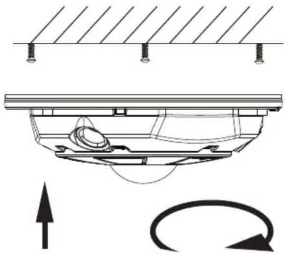
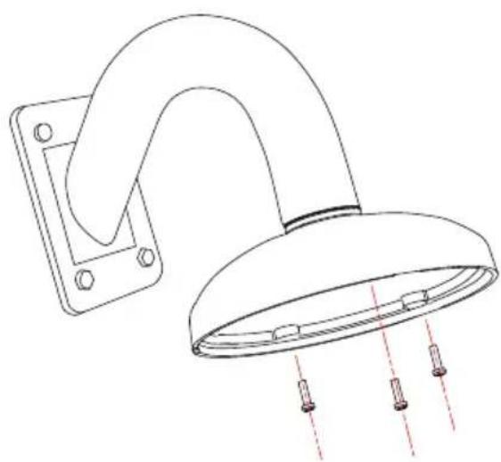
- Insert three (3) supplied screw anchors into the drilled holes in the mounting surface.
-
Use a Phillips screwdriver to insert supplied screws into the screw anchors. Leave enough screw length protruding from the each anchor to allow for the camera body to be rotated onto the screws.
-
Remove the camera cover. Use a Phillips screwdriver to loosen the safety lock screw, then grip the camera cover and flex on one side, towards the center. Lift UP to remove.
- Feed the camera cabling through the cable opening drilled in the mounting surface.
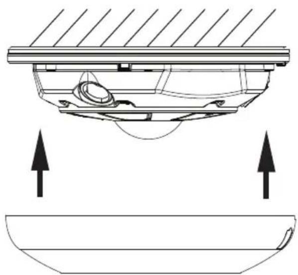
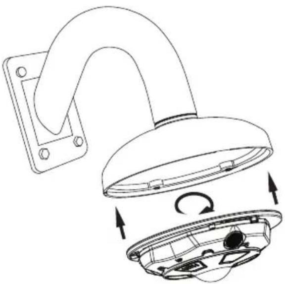
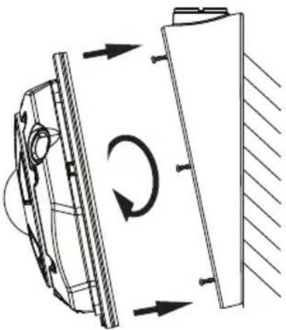
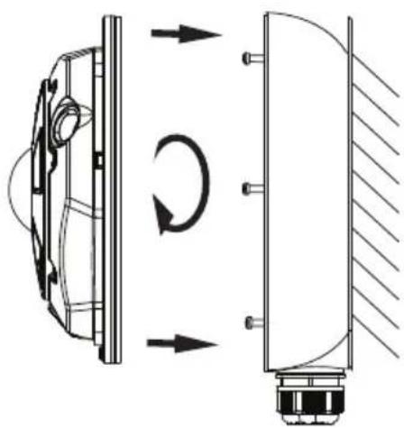
- Slide the protruding mounting screws through three matching mounting screw holes on the camera body and rotate the camera clockwise to secure the camera body on the mounting surface. Use a Phillips screwdriver to tighten three mounting screws in place.
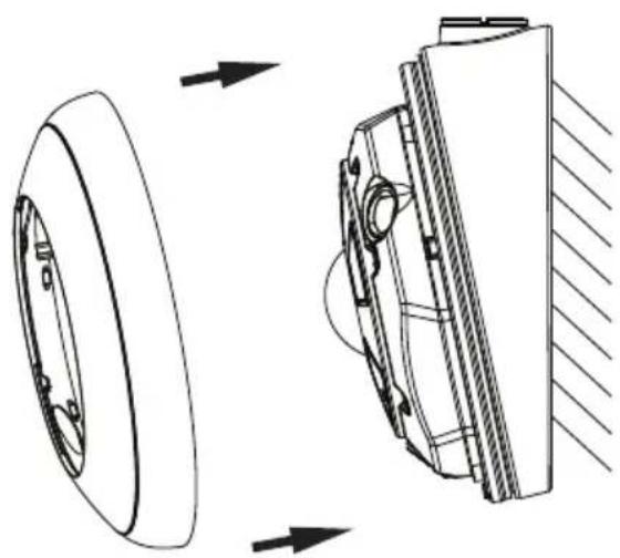
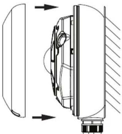
- Replace the camera cover. Match up the safety lock screw with the screw hole on the camera body, then push straight down onto the camera cover to engage the clips. The camera cover will re-attach.
- Use a Phillips screwdriver to re-tighten the safety lock screw.
natural_image
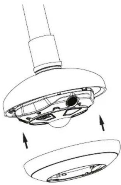
Technical diagram of a mechanical assembly with mounting fixtures and directional arrows (no text or symbols)Figure 10. Surface Mount - Steps 6-7.
natural_image
Technical diagram of a mechanical component with two upward arrows indicating force or movement (no text or symbols present)Figure 11. Surface Mount - Step 8.
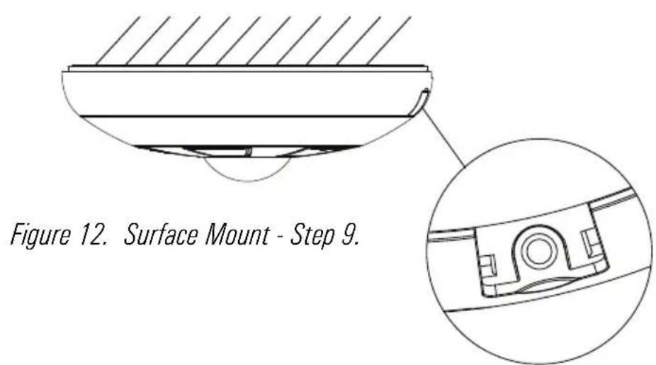
text_image
Figure 12. Surface Mount - Step 9.i3-TRNG-CAMS-68R_78R.indd Rev. 150505
3.4 Wall Mount w/ Back Box and Gooseneck Bracket

Note on supplied mounting hardware and IP66 rating
Based on installation location and surface type, supplied screws and anchors may not be adequate. Mounting hardware is site-specific and may need to be supplied by the installer.
It is the installer's responsibility to ensure that the mounting surface is suitable for installation method.
Use sealant at the locations shown on the mounting diagrams to maintain IP66 rating when installing outside.

text_image
DB60 - Goose-neck Bracket Use silicone to maintain IP66 rating DR78RR - Back hnxFigure 13. Wall-Mount - Step 2.
-
Install the i3 Goose-neck bracket (DB60) on the wall surface using the hardware and instructions supplied with the goose-neck bracket.
-
Attach DB78BB back box to the threaded end of the goose-neck bracket DB60 and rotate clockwise to attach the two together. Use silicone sealer as indicated on the diagram to maintain IP66 rating when installing outside.
natural_image
Technical line drawing of a showerhead with mounting bracket and red dashed lines indicating spray or spray (no text or symbols)Figure 14. Wall-Mount - Step 4.
-
Remove the camera cover. Use a Phillips screwdriver to loosen the safety lock screw, then grip the camera cover and flex on one side, towards the center. Lift UP to remove.
-
Use a Phillips screwdriver to insert three machine-type screws provided with the DB78BB back box into the screw holes on the back box. Leave enough screw length protruding to allow for the camera body to be rotated onto the screws.
-
Feed the camera cabling through the gooseneck bracket.
- Slide the protruding mounting screws through three matching mounting screw holes on the camera body and rotate the camera clockwise to secure the camera body on the mounting surface. Use a Phillips screwdriver to tighten three mounting screws in place.
- Replace the camera cover. Match up the safety lock screw with the screw hole on the camera body, then push straight down onto the camera cover to engage the clips. The camera cover will re-attach.
- Use a Phillips screwdriver to re-tighten the safety lock screw.
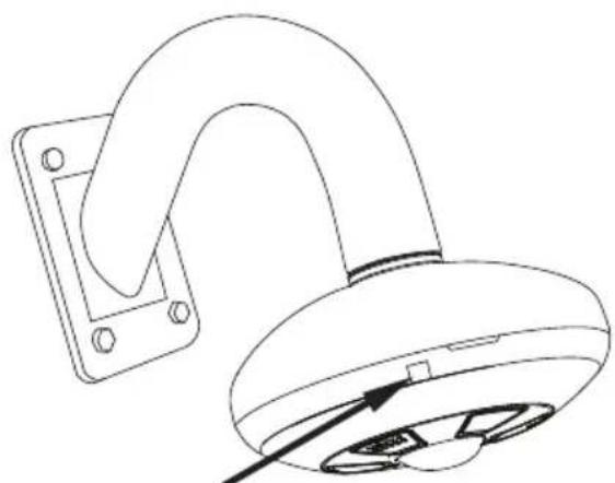
natural_image
Line drawing of a curved mechanical component mounted on a rectangular base, with a pointer indicating force or direction (no text or symbols)Safety lock screw
Figure 17. Wall-Mount - Step 8.
natural_image
Technical line drawing of a ceiling-mounted lamp with internal components and directional arrows indicating rotation (no text or symbols)Figure 15. Wall-Mount - Step 6.
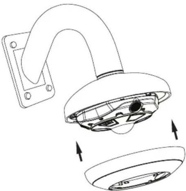
natural_image
Technical line drawing of a wall-mounted device with internal components and directional arrows indicating assembly (no text or symbols)Figure 16. Wall-Mount - Step 7.
3.5 Wall Mount w/ Angle Mount Bracket

Note on supplied mounting hardware and IP66 rating
Based on installation location and surface type, supplied screws and anchors may not be adequate. Mounting hardware is site-specific and may need to be supplied by the installer.
It is the installer's responsibility to ensure that the mounting surface is suitable for installation method.
Use sealant at the locations shown on the mounting diagrams to maintain IP66 rating when installing outside.
Use silicone
to maintain IP66
rating

text_image
rating DB78TSM - Angle-mount BracketFigure 18. Angle-Mount - Step 1.
natural_image
Diagram of a cylindrical object with three parallel lines extending outward, no text or symbols presentFigure 19. Angle-Mount - Step 3.
-
Install the i3 angle-mount bracket (DB78TSM) on the wall surface using the hardware and instructions supplied with the angle mount bracket. Use silicone sealer as indicated on the diagram to maintain IP66 rating when installing outside.
-
Remove the camera cover. Use a Phillips screwdriver to loosen the safety lock screw, then grip the camera cover and flex on one side, towards the center. Lift UP to remove.
-
Use a Phillips screwdriver to insert three machine-type screws provided with the DB78BB back box into the screw holes on the back box. Leave enough screw length protruding to allow for the camera body to be rotated onto the screws.
-
Feed the camera cabling through the angle-mount bracket opening.
natural_image
Technical diagram of a mechanical assembly with directional arrows indicating rotational motion (no text or symbols)Figure 20. Angle-Mount - Step 5.
- Replace the camera cover. Match up the safety lock screw with the screw hole on the camera body, then push straight down onto the camera cover to engage the clips. The camera cover will re-attach.

natural_image
Technical line drawing of a mechanical component with an inset close-up view (no text or symbols)Figure 22. Angle-Mount - Step 7.
- Slide the protruding mounting screws through three matching mounting screw holes on the camera body and rotate the camera clockwise to secure the camera body on the mounting surface. Use a Phillips screwdriver to tighten three mounting screws in place.
natural_image
Technical line drawing of a mechanical assembly showing a wheel and housing with directional arrows (no text or symbols)Figure 21. Angle-Mount - Step 6.
- Use a Phillips screwdriver to re-tighten the safety lock screw.
3.6 Wall Mount w/ Back Box

Note on supplied mounting hardware and IP66 rating
Based on installation location and surface type, supplied screws and anchors may not be adequate. Mounting hardware is site-specific and may need to be supplied by the installer.
It is the installer's responsibility to ensure that the mounting surface is suitable for installation method.
Use sealant at the locations shown on the mounting diagrams to maintain IP66 rating when installing outside.
text_image
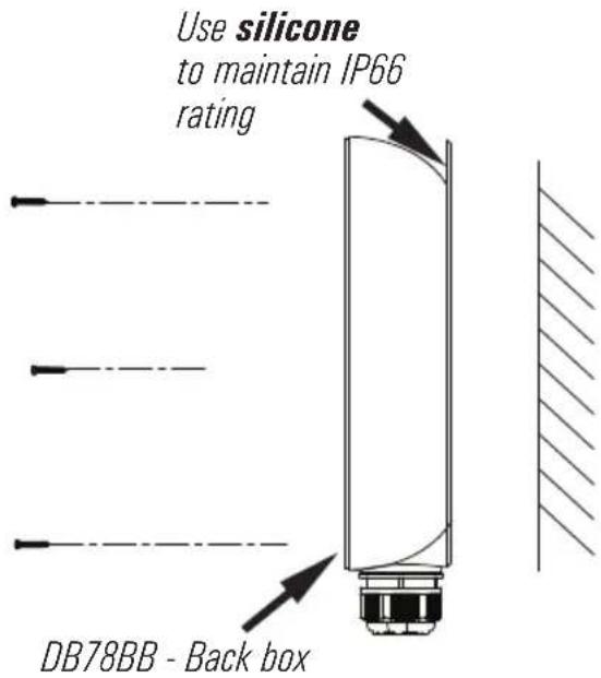
Use silicone to maintain IP66 rating DB78BB - Back boxFigure 23. Angle-Mount - Step 1.

natural_image
Diagram of a vertical optical or mechanical component with three parallel lines and a base, showing no text or symbols.Figure 24. Angle-Mount - Step 3.
- Install the i3 Back Box (DB78BB) on the wall surface using the hardware and instructions supplied with the angle mount bracket. Use silicone sealer as indicated on the diagram to maintain IP66 rating when installing outside.
- Remove the camera cover. Use a Phillips screwdriver to loosen the safety lock screw, then grip the camera cover and flex on one side, towards the center. Lift UP to remove.
- Use a Phillips screwdriver to insert three machine-type screws provided with the DB78BB back box into the screw holes on the back box. Leave enough screw length protruding to allow for the camera body to be rotated onto the screws.
- Feed the camera cabling through the back box opening.
natural_image
Technical diagram showing a mechanical component with rotational flow arrows, no text or symbols presentFigure 25. Angle-Mount - Step 5.
- Replace the camera cover. Match up the safety lock screw with the screw hole on the camera body, then push straight down onto the camera cover to engage the clips. The camera cover will re-attach.

natural_image
Technical line drawing of a mechanical component with an inset close-up view (no text or symbols)Figure 27. Angle-Mount - Step 8.
- Slide the protruding mounting screws through three matching mounting screw holes on the camera body and rotate the camera clockwise to secure the camera body on the mounting surface. Use a Phillips screwdriver to tighten three mounting screws in place.
natural_image
Technical line drawing of a mechanical component with directional arrows indicating movement or force (no text or symbols)Figure 26. Angle-Mount - Step 7.
- Use a Phillips screwdriver to re-tighten the safety lock screw.
3.7 Pendant Pole Mount

Note on supplied mounting hardware and IP66 rating
Based on installation location and surface type, supplied screws and anchors may not be adequate. Mounting hardware is site-specific and may need to be supplied by the installer.
It is the installer's responsibility to ensure that the mounting surface is suitable for installation method.
Use sealant at the locations shown on the mounting diagrams to maintain IP66 rating when installing outside.
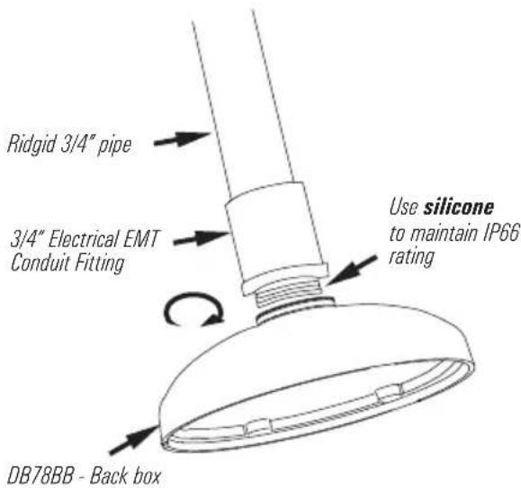
text_image
Ridgid 3/4" pipe 3/4" Electrical EMT Conduit Fitting Use silicone to maintain IP66 rating DB78BB - Back boxFigure 28. Pendant-Mount - Step 2.
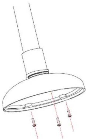
natural_image
Technical line drawing of a showerhead with three screw holes and red dashed lines indicating spray or positioning (no text or symbols)Figure 29. Pendant-Mount - Step 4.
- Use a 3/4" Electrical EMT Conduit Fitting with a ridgid 3/4" pipe for this type of installation.
- Attach DB78BB back box to the threaded end of the 3/4" Electrical EMT Conduit Fitting and rotate clockwise to attach the two together. Use silicone sealer as indicated on the diagram to maintain IP66 rating when installing outside.
- Remove the camera cover. Use a Phillips screwdriver to loosen the safety lock screw, then grip the camera cover and flex on one side, towards the center. Lift UP to remove.
- Use a Phillips screwdriver to insert three machine-type screws provided with the DB78BB back box into the screw holes on the back box. Leave enough screw length protruding to allow for the camera body to be rotated onto the screws.

natural_image
Technical line drawing of a mechanical component with internal rotation arrows (no text or symbols)- Replace the camera cover. Match up the safety lock screw with the screw hole on the camera body, then push straight down onto the camera cover to engage the clips. The camera cover will re-attach.
text_image
Safety lock screw-
Feed the camera cabling through the ridgid pipe bracket.
-
Slide the protruding mounting screws through three matching mounting screw holes on the camera body and rotate the camera clockwise to secure the camera body on the mounting surface. Use a Phillips screwdriver to tighten three mounting screws in place.
natural_image
Technical line drawing of a mechanical component with internal parts and directional arrows indicating assembly (no text or symbols)- Use a Phillips screwdriver to re-tighten the safety lock screw.
4. Connecting Ax68R/78R to SRX-Pro Server
4.1 Network Topology Options
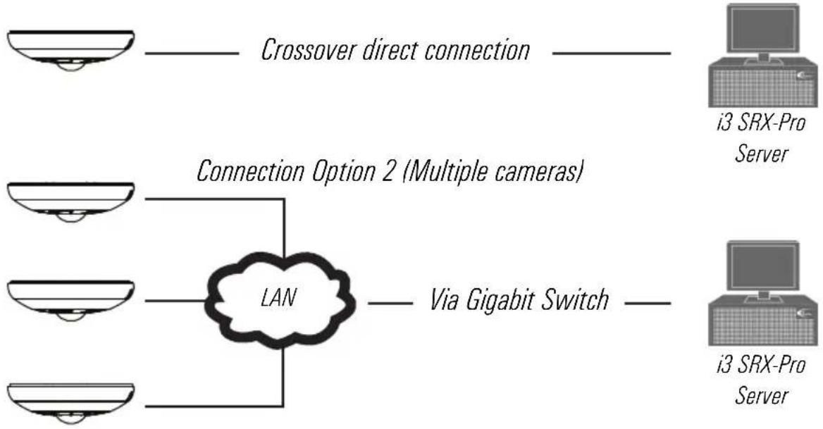
Connection Option 1 (Single camera)
Important: Must use 12V DC Power for this connection type. PoE not supported.
flowchart
graph LR
    A["Crossover direct connection"] --> B["Connection Option 2 (Multiple cameras)"]
    B --> C["LAN"]
    C --> D["Via Gigabit Switch"]
    E["i3 SRX-Pro Server"] --> F["i3 SRX-Pro Server"]
4.2 Hardware/Software Requirements
The following requirements must be met to achieve a successful network connection with the Ax68R/78R-series IP camera.
SRX-Pro Server
• i3 SRX-Pro Version 3.0 or higher
- Latest GiPi adapter is installed. GiPi adapters can be downloaded from i3 Downloads web page. (Please contact i3 Technical Support for more information.)
• Windows XP, XPe, 7 Pro or 7e
- Internet Explorer Version 8.0 or later
• CPU: Intel Pentium Core 2 or higher
• Memory: 1GB or more
• VGA card--supporting DirectX 9.0 or above
Switch
A Gigabit Switch is required to monitor two or more cameras from the same SRX-Pro Server.
4.3 Configuring Internet Explorer for Video Display
Your Internet Explorer (v.8.0 or higher) must first be configured in order to properly display video stream from your Annexus camera.
Follow these instructions to configure your Internet Explorer browser.
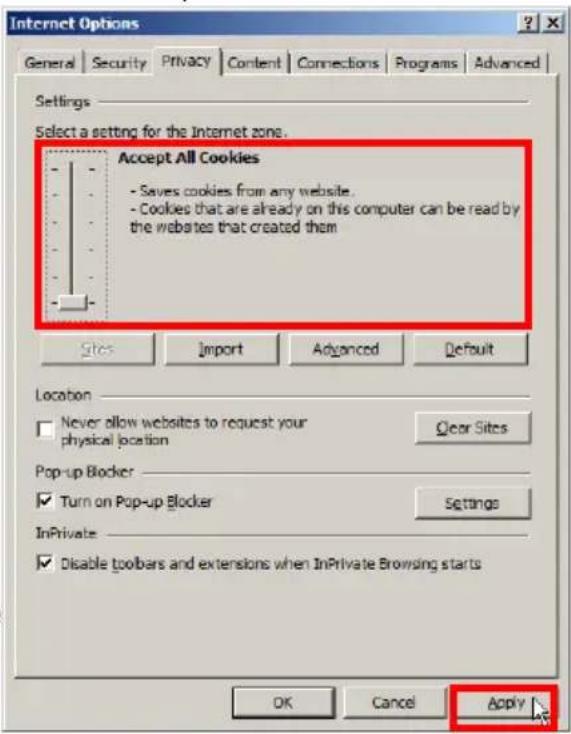
Enable Cookies
- In Internet Explorer window, click Tools -> Internet Options
-
Open Privacy tab, move the slider to "Low" or "Accept All Cookies"
-
Click Apply. Do not close the Internet Options window.
Adjust Internet Security Settings
- Open Security tab in the Internet Options window
-
If the camera operates inside of the Intranet, click the Intranet icon; If the camera operates outside of the Intranet, click the Internet icon.
-
Click Custom Level. Security Settings - Internet Zone window will be displayed.
-
Scroll down to the ActiveX controls and plug-ins radio buttons and configure as follows:
»Automatic prompting for ActiveX controls -> Enable
»Download signed ActiveX controls -> Prompt (recommended)
»Download unsigned ActiveX controls -> Prompt
»Initialize and script ActiveX not marked as safe for scripting -> Prompt
»Run ActiveX controls and plug-ins -> Enable
text_image
Internet Options General Security Privacy Content Connections Programs Advanced Settings Select a setting for the Internet zone. Accept All Cookies - Saves cookies from any website. - Cookies that are already on this computer can be read by the websites that created them Sites Import Advanced Default Location Never allow websites to request your physical location Clear Sites Pop-up Blocker Turn on Pop-up Blocker Settings InPrivate Disable toolbars and extensions when InPrivate Browsing starts OK Cancel Apply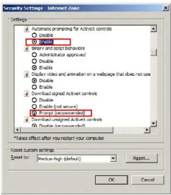
text_image
Security Settings - Internet Zone Settings Automatic prompting for ActiveX controls Disable Enable Binary and script behaviors Administrator approved Disable Enable Display video and animation on a webpage that does not use Disable Enable Download signed ActiveX controls Disable Enable (not secure) Prompt (recommended) Download unsigned ActiveX controls Disable (recommended) *Takes effect after you restart your computer Reset custom settings Reset to: Medium-high (default) Reset... OK Cancel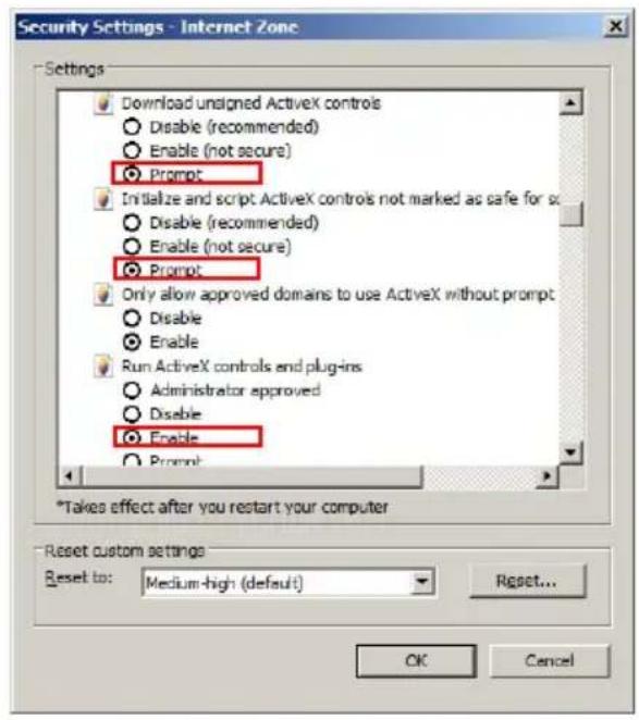
text_image
Security Settings - Internet Zone Settings Download unsigned ActiveX controls Disable (recommended) Enable (not secure) Prompt Initialize and script ActiveX controls not marked as safe for so Disable (recommended) Enable (not secure) Prompt Only allow approved domains to use ActiveX without prompt Disable Enable Run ActiveX controls and plug-ins Administrator approved Disable Enable Prompt *Takes effect after you restart your computer Reset custom settings Reset to: Medium-high (default) Reset... OK Cancel
text_image
Security Settings - Internet Zone Settings Prompt Only allow approved domains to use ActiveX without prompt Disable Enable Run ActiveX controls and plug-ins Administrator approved Disable Enable Prompt Run antimalware software on ActiveX controls Disable Enable Script ActiveX controls marked safe for scripting* Disable Enable Enable Prompt *Takes effect after you restart your computer Reset custom settings Reset to: Medium-high (default) Reset... OK Cancel» Script ActiveX controls marked safe for scripting -> Enable
- Click OK to save the Internet Security Settings
- Close all Microsoft Internet Explorer windows and open a new IE window. This will allow the new settings to take effect.
4.4 Testing Ax68R/78R Camera in Internet Explorer
- Open a new Internet Explorer window.
- Enter Ax68R/78R camera default IP address: 192.0.0.16
- In the Annexus login screen, enter the default camera user name: i3admin and default password: i3admin
- Annexus camera interface will be displayed in the Internet Explorer window. Live video stream will be displayed on the screen. If you do not see live video image on the screen, call i3 International tech support for help.
- Proceed to the following sections to assign a unique IP address to your Ax68R/78R camera and to add it to your SRX-Pro Server.
Note: You may be required to install ActiveX Controller in the IE browser before being able to view camera's live view video steam.

text_image
i³ INTERNATIONAL ANNEXXUS INTUITIVE VIDEO PRODUCTS User Name admin Password ••••• Login4.5 Assigning New IP Address to Ax68R/78R with Annexus Configuration Tool.
Camera's default IP address is 192.0.0.16
Camera's default Subnet mask address is 255.255.255.0.
Default camera User Name: i3admin and default Password: i3admin
To add your Annexus IP camera to SRX-Pro Server, assign a unique IP address:
- Close SRX-Pro Server software by pressing Alt+Shift+Ctrl+F4.
- Change the IP address on the onboard NIC (LAN) (or on NIC1 if your SRX-Pro Server has two onboard NIC cards) of your SRX-Pro Server to 192.0.0.XXX to match the default IP range of your Annexus IP camera.
- Connect the network cable from the SRX-Pro Server (crossover direct connection) or from the Gigabit switch to your Annexus camera.
Important: 12V DC power must be used with this connection type. PoE is not supported with crossover connection. - Turn on your Annexus camera.
- Locate the CD that came with your Annexus camera and insert it in the CD-ROM drive of your SRX-Pro Server.
- Double-click "setup.exe" file to install Annexus Configuration Tool (ACT) application. ACT application discovers all Annexus cameras connected to your network.
- Follow the ACT installation instructions until the application has been successfully installed on your SRX-Pro Server.
text_image
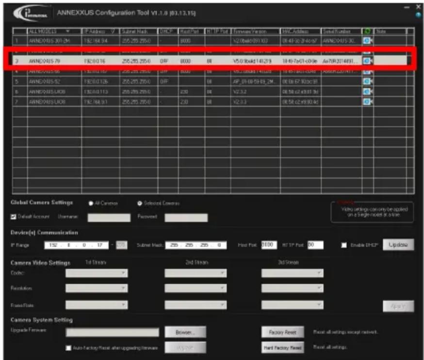
ANNEXXUS Configuration Tool V1.1.0 (83.13.15j) ALL NO.05.13 IP Address: 7 Subnet Mask: 255,255,255.0 OFF Heat Port HT IP Port Features Version WPC Address Serial Number Note 1 ANNEXXUS 301.24 192.164.94 255,255,255.0 - 8000 V2.0xk1091.03 DE 4F 2C 3F 4F ANNEXXUS 30. 2 ANNEXXUS 79 192.0.0.16 255,255,255.0 OFF 8000 V5.0.9xk1141.219 1H 4F 7x01-09:96 Av75R2014931... ANNEXXUS 56 192.0.0.167 255,255,255.0 OFF 8000 V5L 18x88.14x88.0 1H 4F 7x01-09:96 Av75R2014931... ANNEXXUS 52 192.0.0.126 255,255,255.0 OFF 80 AP_01/08/59/63_2M_ DE 06/67:90:09:91 ANNEXXUS LIOB 192.0.0.113 255,255,255.0 - 250 V2.3.2 DE 58 c2 x3:31.3d ANNEXXUS LIOB 192.164.91 255,255,255.0 - 230 V2.3.3 DE 58 c2 x9:30.4d Global Camera Settings All Camera Selected Camera: Default Account Username: Recovered: Device(s) Communication IP Range 152 8 0 17 - 275 Subnet Mask: 255 255 255 0 Host Port: 8100 HT IP Port 80 Enable DHCP® Update Camera Video Settings 1st Stream 2nd Stream 3rd Stream Code: - - - - - - - - - - - - - - - - - - - - - - - - - - - - - - - - - - - - - - - - - - - - - - - - - - - - - - - - - - - - - - - - - - - - - - - - - - - - - - - - - - - - - - - - - - - - - - - - - - - - + - Camera System Setting Upgrade Forearm: Browser... Factory Reset Reset all settings except network. Auto Factory Reset after uploading Forearm: Hi-7-20% Reset all settings.- Double-click ACT icon on the Desktop to launch the application.
The application window will appear displaying a list of active network cameras
- Next, select one or more desired Ax68/78 cameras in the ACT software.
To select a single camera, click on the camera line in the list.
To select multiple consecutive cameras, click while holding the Shift key.
text_image
Global Camera Settings All Cameras Selected Cameras Default Account Username Password Video settings can only be applied on a Single model at a time. Device(s) Communication IP Range 192 0 0 17 - 255 Subnet Mask 255 255 255 0 Host Port 8000 HTTP Port 80 Enable DHCP UpdateTo select non-consecutive cameras, click while holding the Ctrl key.
To select all cameras, select All Cameras under Global Camera Settings.
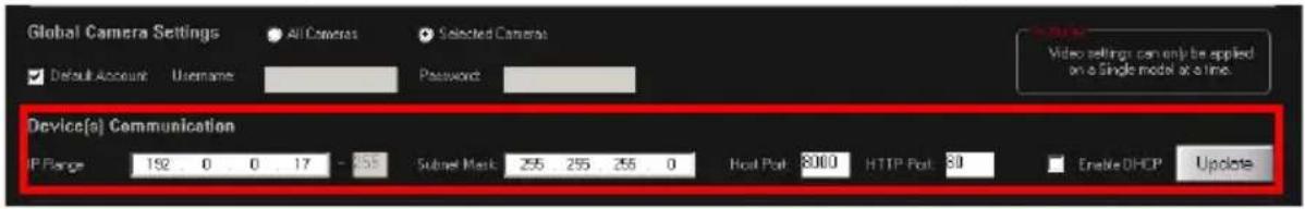
- Enter the new IP address and Subnet Mask of the camera in the Device Communication area. The new camera IP address must match the original range of your SRX-Pro LAN or NIC1 card. E.g. If your original SRX-Pro Server's IP address was 192.168.1.122, change your Annexus camera's IP address to 192.168.1.XXX.
Remember: Annexus Cameras cannot share an IP address, each camera requires its own unique IP address.
See Annexus Configuration Tool User Manual for detailed instructions on changing IP Address on multiple cameras at the same time.
text_image
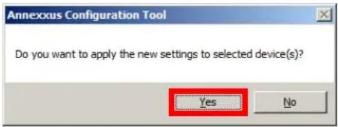
Annexus Configuration Tool Do you want to apply the new settings to selected device(s)? Yes No- Make sure the Default account checkbox is checked and click Update.
- Click Yes in the confirmation message window.
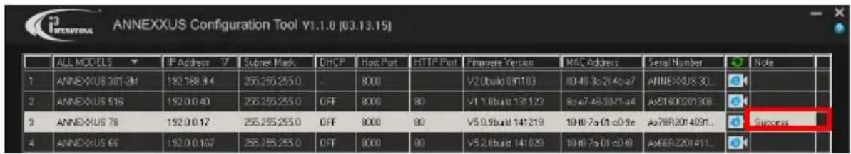
text_image
ANNEXXUS Configuration Tool V1.1.0 (03.13.15) ALL MODELS IP Address 7 Subset Mask DHCP Host Port HTTP Port Firmware Version MAC Address Serial Number Note 1 ANNEXUS 301-2M 192.168.94 256.255.255.0 OFF 8000 V2.0build 091103 00:40 &2:4c:a7 ANNEXUS 30... 2 ANNEXUS 518 192.0.0.40 256.255.255.0 OFF 8000 V1.1.0build 131123 8c:e7 48:30:1a4 AeB1800201308 3 ANNEXUS 78 192.0.0.17 256.255.255.0 OFF 8000 V5.0.9build 141219 19:46-7a:01-c0:9e Ae78R2014091... Success 4 ANNEXUS 69 192.0.0.167 256.255.255.0 OFF 8000 V5.2.0build 141029 19:46-7a:01-c0:49 Ae68R201411...- Wait a few moments as the new IP address is being applied to your Annexus camera. Wait for the Success message to be displayed in the camera list.
- Repeat Steps 1-13 for all detected Annexus cameras in the Annexus Configuration Tool.
- Now that the new IP address has been successfully assigned to your camera, make sure you can connect to it through the Internet Explorer:
- Select the camera in list and click the corresponding IE icon.

- Annexus camera Password window will be displayed.
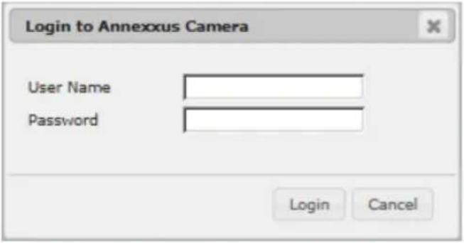
text_image
Login to Annexus Camera User Name Password Login Cancel- Enter the default camera User Name: i3admin and default Password: i3admin
- Allow ActiveX Add-on to be installed onto your computer. Click Allow.

text_image
This webpage wants to run the following add-on: "WebVideoActiveX" from "Not Available". What's the risk? Allow- Annexus camera interface will be displayed in the Internet Explorer window. Live video stream will be displayed on the screen. If you see Live video image, the IP address has been successfully changed. Proceed to the next section. Note: If you do not see live video image on the screen, call i3 International tech support for help.

text_image
Channels ANNEXOUS 78 ANNEXOUS 1 ANNEXOUS 2 PTZ Controls Speed: 50 Select Present: Preset 1 Go to Preset Set Preset Video Adjustments Brightness: 50 Contrast: 50 Saturation: 50 Sharpness: 50 Hue: 50 Default Save Audio Settings Encoding: 0.711 Audio In Micin Audio Out CF Volume In 30 Volume Out 30 Enable Two-way audio Save Users Cadman4.6 Adding your IP Camera to your SRX-Pro Server
- Make sure that the latest version of GiPi updater is installed on your SRX-Pro Server. You can download the updates from http://i3international.com/index.php/software-downloads
- Once the latest GiPi updater has been installed, restart i3 SRX-Pro Server software.
- Log In and go to the Setup -> IP Camera tab.
- Click the Search button to display connected Annexus cameras.
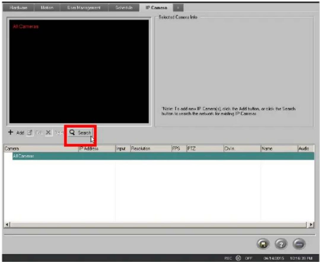
text_image
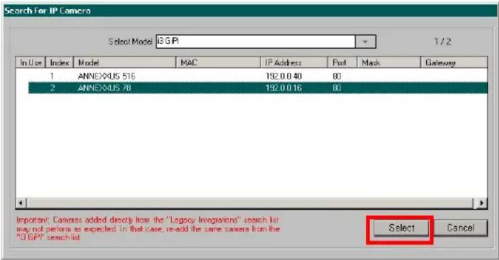
Hardware Motion User Management Schedule IP Camera All Cameras Selected Camera Info *Note: To add new IP Camera(s), click the Add button, or click the Search button to search the network for existing IP Cameraas + Add Add Edit Delete Search Camera IP Address Input Resolution FPS PTZ Chin. Name Audio AI Camera REC OFF 04/14/2015 10:16:39 PM- Select the detected camera in the list and click Select.
text_image
Search For IP Camera Select Model i3GP 1/2 In Use Index Model MAC IP Address Post Mask Gateway 1 ANNEXUS 516 192.0.0 40 80 2 ANNEXUS 78 192.0.0 16 80 Important: Cameras added directly from the "Legacy Integrations" search list may not perform as expected in that case, re-add the same camera from the "3GP" search list Select Cancel- In the Select IP Camera window, enter the default camera
User Name: i3admin and default Password: i3admin, then click Add.

text_image
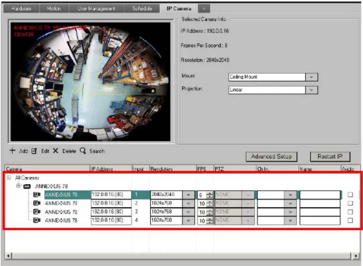
Select IP Camera IP Camera Info Model: i3GIF Search IP Address: 192.0.0.16 ANNEXUS Port: 80 Server MAC: 18.18.7x.01.c0.9e Server Subnet: 255.255.255.0 Server Gateway: 192.0.0.1 Video Input: 1 Select All Name: User Accounts User Name i3admin Password ****** Add Close- The selected camera will be added to the IP Camera list.
text_image
Hardware Motion User Management Schedule IP Camera ANNEXUS 78: 192.0.0.16 (80) 720x720 Selected Camera Info IP Address: 192.0.0.16 Frames Per Second: 6 Resolution: 2048x2048 Mount Ceiling Mount Projection: Linear Add Edit Delete Search Advanced Setup Restart IP Camera IP Address Input Resolution EPS PTZ Ch In. Name Audio All Cameras ANNEXUS 78 ANNEXUS 78 152.0.0.16 (80) 1 2048x2048 6 NONE ANNEXUS 78 152.0.0.16 (80) 2 1024x758 10 NONE ANNEXUS 78 152.0.0.16 (80) 3 1024x758 10 NONE ANNEXUS 78 152.0.0.16 (80) 4 1024x758 10 NONEAnnexxus 68/78 Channels
Ax68/78 cameras support four (4) separate video channels/inputs, all four are detected and added to IP Camera setup tab of the SRX-Pro Server automatically. Only one (1) IP license is required for all four channels. Channel 1 - 360-degree fisheye video input, supports Main and Sub streams. Channels 2-4 - three separate dewarped video streams that can be used as PTZ channels.
- Assign the first Channel (360-degree view) to the SRX-Pro video channel in the Ch In. column (mandatory). Assign the remaining three PTZ channels to other SRX-Pro video channels (optional).

text_image
All Cameras ANNEXUS 78 ANNEXUS 78 192.0.0.16 (80) 1 2048x2048 6 NONE 1. Annexus ANNEXUS 78 192.0.0.16 (80) 2 1024x768 10 NONE 1 Annexus 78R ANNEXUS 78 192.0.0.16 (80) 3 1024x768 10 NONE 2 Annexus 78R ANNEXUS 78 192.0.0.16 (80) 4 1024x768 10 NONE 3 Annexus 78R 5 Channel5 6 Channel6 7 Channel7 8 Channel8 9 Channel9- Assign i3 GiPi PTZ to each Channel to enable digital PTZ (ePTZ) function.

text_image
Camera IP Address Input Resolution FPS FTZ Ch In. Name Audio AI Camera ANNEXUS 78 ANNEXUS 78 192.0.0.16 (80) 1 2048x2048 6 3 GPi 1. Annexus ANNEXUS 78 192.0.0.16 (80) 2 1024x768 10 NONE ANNEXUS ANNEXUS 78 192.0.0.16 (80) 3 1024x768 10 3 GPi 3. Annexus ANNEXUS 78 192.0.0.16 (80) 4 1024x768 10 3 GPi 4. Annexus- Save the settings.

Your Annexus camera is now connected to SRX-Pro Server and is ready to record. You may change resolution and frame rate for each of the four video streams in the IP Camera tab menu or you may choose to configure the camera's advanced settings (see the following section).
Tip: In SRX-Pro Server, ensure that Motion Setup, Schedule Setup and Storage setup tabs are correctly configured for video recording.