EX5005CKIT - Compressor ExelAir - Free user manual and instructions
Find the device manual for free EX5005CKIT ExelAir in PDF.

User questions about EX5005CKIT ExelAir
0 question about this device. Answer the ones you know or ask your own.
Ask a new question about this device
Download the instructions for your Compressor in PDF format for free! Find your manual EX5005CKIT - ExelAir and take your electronic device back in hand. On this page are published all the documents necessary for the use of your device. EX5005CKIT by ExelAir.
USER MANUAL EX5005CKIT ExelAir
GENERAL SAFETY RULES......2
AIR SUPPLY....5
PRODUCT DESCRIPTION....7
TECHNICAL SPECIFICATIONS....10
ASSEMBLY....11
1/2" Air Impact Wrench....11
3/8" Air Ratchet Wrench....13
Air Hammer....14
1/4" Air Die Grinder....16
OPERATION....19
1/2" Air Impact Wrench....19
3/8" Air Ratchet Wrench....20
Air Hammer....20
1/4" Air Die Grinder....21
TROUBLESHOOTING....22
CARE AND MAINTENANCE....22
EXPLODED DIAGRAMS AND PARTS LISTS....23
1/2" Air Impact Wrench....23
3/8" Air Ratchet Wrench....24
Air Hammer....25
1/4" Air Die Grinder....26
WARRANTY....27

WARNING!
- Improper operation or maintenance of this tool could result in personal injury and/or property damage. Read and understand all warnings and operation instructions before using this tool.
- When using this tool, these basic safety precautions should always be followed to reduce the risk of personal injury and/or property damage.
Workplace conditions
- Always work in a clean, dry, well-ventilated area free of combustible materials. Never operate the tool near flammable substances such as gasoline, naphtha, cleaning solvent, etc.
- Dress properly. Do not wear loose clothing. Tie up or cover long hair, remove any jewelry, necklaces, etc., which might become caught by the tool.
- Keep the work area well lit and free of clutter. Slips, trips and falls are major causes of workplace injury. Be aware of excess air hose left in your walking way or on the working surface.
- Ensure that there are no electrical cables, gas pipes, etc., which can cause a hazard if damaged by use of the tool.
- Keep visitors a safe distance from the work area. Keep children away.
Use of air tools
-
Stay alert and use common sense. Watch what you are doing. Do not operate the tool when you are tired or under the influence of alcohol, drugs or medication.
-
Do not overreach. Keep proper footing and balance at all times.
-
Always wear eye protectors which provides protection from flying particles from the front and side when using the tool. Ear protectors should also be worn.
-
Never use oxygen, carbon dioxide, combustible gases or any other type of bottled gases as a power source for this tool.
-
Always verify prior to using this tool that the air source has been adjusted to the rated air pressure range. Never connect to an air source that is capable of exceeding 200psi.
-
Do not connect the air supply hose to the tool with your finger on the trigger.
-
Do not exceed the maximum working pressure 90psi/6.3bar for the tool. Excessive pressure will reduce the tool life and/or might cause a hazardous situation.
-
Never leave the operating tool unattended. Disconnect the air hose when the tool is not in use.
-
Keep the air supply hose away from heat, oil and sharp edges.
-
Check the air supply hose for wear and/or leaks before each use. Make sure that all connections are tight and secure.
-
Do not use the tool for any other than its intended use.
-
Do not carry out any alterations and/or modifications to the tool.
-
Always disconnect the tool from air supply before replacing any accessories, performing any repair and maintenance, moving to another work area, or passing the tool to another person.
-
Never use the tool if it is defective, damaged, or operating abnormally.
- Check for misalignment or binding of moving parts, breakage of parts and any other condition that affects the tool operation. If damaged, have the tool serviced before using.
- Keep working parts of the tool away from hands and body.
- Do not carry the tool by the air hose.
- Do not apply excessive force of any kind to the tool. Let the tool perform the work at the rate as it was designed.
- Do not remove any labels on the tool. Replace if they become obscured or damaged.
- Always maintain the tool with care. Keep it clean for the best and safest performance.
- It is not recommended that quick change couplings should be located directly at the air inlet, as they add weight and could fail due to vibration.
- This tool vibrates with use. Continuous operation of this tool might be harmful to your hands or arms. Stop using the tool if discomfort, a tingling feeling or pain occurs. Resume work after recovery. Seek medical advice if a serious symptom occurs.
Air impact wrench safety instructions
-
Always use the impact wrench in the manner and for the functions described in this manual.
-
Always ensure the wrench is not moving and disconnected from the air supply when changing sockets etc. Only use impact sockets. Do not use standard sockets.
-
Always finish tightening wheel nuts or engine parts with a torque wrench or suitable spanner to the correct torque as recommended by the vehicle manufacturer.
-
Always avoid excessive use of the impact wrench. When tightening a nut or bolt, never allow the wrench to impact more than 8 times. This is to avoid over-tightening. 3 to 4 impacts is normally sufficient.
-
Always ensure that the socket is correctly installed onto the tool anvil before starting the tool.
-
Due to the possible presence of asbestos dust from brake linings, always wear suitable respiratory protection.
-
Never carry the impact wrench by the air supply hose.
-
Always disconnect the tool from the air supply when changing impact sockets or when the wrench is not required for immediate use in order to avoid accidental start.
-
Hold the tool correctly. Always use both hands to control the impact wrench.
-
Always ensure that the wrench has come to a complete stop before putting it down after use.
- If necessary, use clamps or proper devices to securely fix the workpiece when installing/tightening or removing/loosening threaded fasteners on the workpiece.
- For overhead work, wear a safety helmet.
- Do not discard the safety instructions. Give them to the operator.
- Always store this product in a dry and safe place out of reach of children or untrained operators.
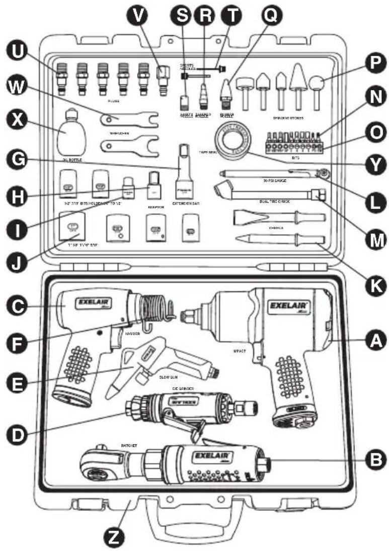
50-PIECE COMPOSITE AIR TOOL KIT
Air ratchet wrench safety instructions
- Always use the ratchet wrench in the manner and for the functions described in this manual.
- Always ensure the wrench is not moving and disconnected from the air supply when changing sockets etc. Only use impact sockets. Do not use standard sockets.
- Always finish tightening threaded fasteners, bolts or nuts, or engine parts with a calibrated torque wrench by hand to the correct torque as recommended by the manufacturer where critical torque values are required.
- Where critical torque values are not required, the final tightening of threaded fasteners, bolts or nuts can be slightly tighter if gaskets are used between surfaces.
- Use penetrating oil to assist in freeing off rusted fasteners, bolts and nuts if necessary.
- When assembling, first turn fasteners, bolts or nuts by hand onto workpiece. Then start the tool for tightening.
- Always ensure that the socket is correctly installed onto the tool anvil before starting the tool.
- Never carry the ratchet wrench by the air supply hose.
- Always disconnect the tool from the air supply when changing sockets or when the wrench is not required for immediate use in order to avoid accidental start.
- Always ensure that the wrench has come to a complete stop before putting it down after use.
- If necessary, use clamps or proper devices to securely fix the workpiece when installing/tightening or removing/loosening threaded fasteners on the workpiece.
- For overhead work, wear a safety helmet.
- Do not discard the safety instructions. Give them to the operator.
- Always store this product in a dry and safe place out of reach of children or untrained operators.
Air hammer safety instructions
- Always use the air hammer in the manner and for the functions described in this manual.
- Always ensure the tool is disconnected from the air supply when changing chisels.
- Only use qualified chisels with sharp point or edge. Never use blunt chisels which require excessive pressure and can break from fatigue.
- Always ensure that the chisel is correctly installed onto the tool before starting the tool.
- Never contact the chisel during and after use as it can be hot and sharp. Wear suitable gloves to protect hands.
- If necessary, use clamps or proper devices to securely fix the workpiece.
- Hold the tool firmly. Always use both hands to control the air hammer.
- Make sure that there are no hidden electrical cables, gas pipes etc. inside or around the workpiece to be free of a hazard if damaged by action of the chisels.
- Never carry the tool by the air supply hose.
- Always disconnect the tool from the air supply when the tool is not required for immediate use in order to avoid accidental start.
- Always ensure that the tool has come to a complete stop before putting it down after use.
- Do not discard the safety instructions. Give them to the operator.
50-PIECE COMPOSITE AIR TOOL KIT
- Always store this product in a dry and safe place out of reach of children or untrained operators.
Air die grinder safety instructions
- Always use the die grinder in the manner and for the functions described in this manual.
- Always ensure the grinder is not moving and disconnected from the air supply when changing grinding stones etc.
- Only use qualified grinding stones. Never use chipped or cracked grinding stones.
- Always ensure that the grinding stone is correctly installed onto the tool before starting the tool.
- Avoid direct contact with the grinding stone during and after use as it can be hot and sharp. Wear suitable gloves to protect hands.
- Use respiratory protection when working in certain materials which creates emission of dust and fumes.
- If necessary, use clamps or proper devices to securely fix the workpiece.
- Never carry the grinder by the air supply hose.
- Always disconnect the tool from the air supply when the grinder is not required for immediate use in order to avoid accidental start.
- Always ensure that the grinder has come to a complete stop before putting it down after use.
- Do not discard the safety instructions. Give them to the operator.
- Always store this product in a dry and safe place out of reach of children or untrained operators.
AIR SUPPLY
Please refer to the typical air system layout recommended below.

WARNING! Compressed air can be dangerous. Ensure that you are familiar with all precautions relating to the use of compressors and compressed air supply.
- Use only clean, dry, regulated compressed air as the power source.
- Make sure that the air compressor being used for the tool operation supplies the correct output (CFM).
- Have the tool in "off" position when connecting the tool to the air supply.
- Use normal 90psi working pressure for the tool. High pressure and unclean air will shorten the tool life due to the faster wear and also may create a safety hazard.
- Drain water from the air compressor tank daily, as well as any condensation in the air lines. Water in the air line may enter the tool and cause damage to the tool mechanisms at operation.
- Clean the tool air inlet screen filter for blockage weekly. Clean if necessary.
- Usually a 3/8" (inner diameter) air hose is recommended for air supply and airflow to get the optimum performance of tool.
- A long air hose (usually over 25 feet) may cause up to 15psi drop in pressure, so you need to set the output pressure of the air compressor higher to maintain the required working pressure at the tool.
50-PIECE COMPOSITE AIR TOOL KIT
- Use proper hoses and fittings. We do not suggest connecting quick change couplings directly to the tool since they may cause failure due to tool vibration at operation. Instead, add a lead hose and connect coupling between air supply and hose whip.
- Check hoses for wear before each use. Make certain that all connections are in securely.

text_image
Technical diagram of a mechanical or fluid system with numbered components, likely an engine or pump assembly.AIR SYSTEM LAYOUT:
- Air Tool
- Air Hose 3/8" (I.D.)
- Oiler
- Pressure Regulator
-
Filter
-
Shut Off Valve
- Whip Hose
- Coupler Body And Connector
- Drain Daily
-
1/2" Or Larger Pipe And Fitting
-
Air Dryer
- 1" Or Larger Pipe And Fitting
- Air Compressor
- Auto Drain
- Drain Daily
text_image
V SRT Q U W X G H I J C K F A B D E B F E M N O P Q PLUGS WINGSHK 50 BOTTLE TAM PEAL BTS 30-FG GNGZ DUAL TIRE CHICK CREAM EXELAIR EXELAIR EXELAIR IMPACT SLOW SUN GE GROCK DATOET EXELAIR Z| PART | DESCRIPTION | QUANTITY |
| A | 1/2" Air Impact Wrench | 1 |
| B | 3/8" Air Ratchet Wrench | 1 |
| C | Air Hammer | 1 |
| D | 1/4" Air Die Grinder | 1 |
| E | Blow Gun | 1 |
| F | Spring Retainer | 1 |
| G | 3" Extension Bar | 1 |
| H | 3/8" to 1/2" Adaptor | 1 |
| I | Bit Holder | 1 |
| J | 1/2" Dr. Impact Socket | 6 |
| K | Chisel | 2 |
| L | 50-psi Tire Gauge | 1 |
| M | Dual Tire Chuck | 1 |
| DESCRIPTIONPART | QUANTITY | |
| N | Screwdriver Bit | 10 |
| O | Bit Base | 1 |
| P | Grinding Stone | 5 |
| Q | Rubber Nozzle | 1 |
| R | Tapered Nozzle | 1 |
| S | Safety Nozzle | 1 |
| T | Sports Needle | 2 |
| U | Male Plug | 5 |
| V | Female Plug | 1 |
| W | Wrench | 2 |
| X | Oil Bottle | 1 |
| Y | Seal Tape | 1 |
| Z | Case | 1 |
50-PIECE COMPOSITE AIR TOOL KIT
text_image
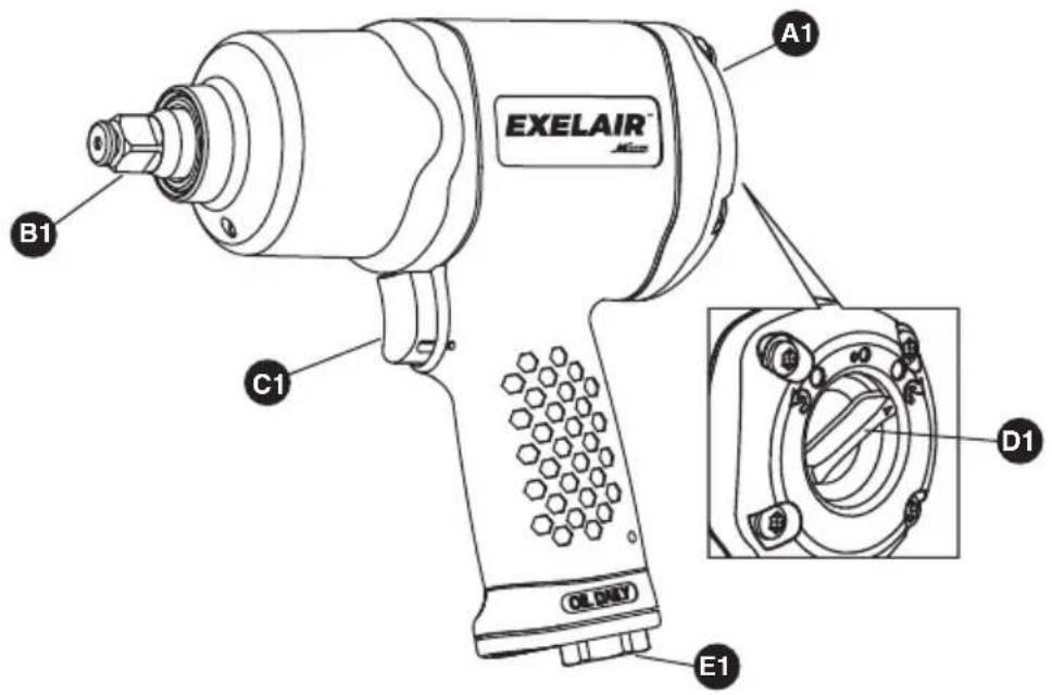
EXELAIR A1 B1 C1 D1 E11/2" AIR IMPACT WRENCH
| PART | DESCRIPTION | QUANTITY |
| A1 | 1/2" Air Impact Wrench | 1 |
| B1 | Anvil | 1 |
| C1 | Trigger | 1 |
| D1 | Switch | 1 |
| E1 | Air Inlet | 1 |

text_image
C2 A2 B2 EXELAIR® D2 E23/8" AIR RATCHET WRENCH
| PART | DESCRIPTION | QUANTITY |
| A2 | 3/8" Air Ratchet Wrench | 1 |
| B2 | Anvil | 1 |
| C2 | F/R Knob | 1 |
| D2 | Trigger | 1 |
| E2 | Air Inlet | 1 |
50-PIECE COMPOSITE AIR TOOL KIT
text_image
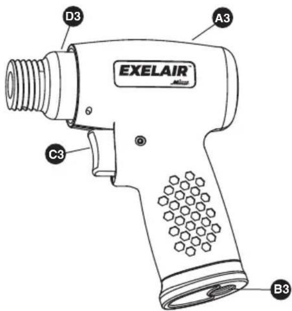
EXELAIR D3 A3 C3 B3AIR HAMMER
| PART | DESCRIPTION | QUANTITY |
| A3 | Air Hammer | 1 |
| B3 | Air Inlet | 1 |
| C3 | Trigger | 1 |
| D3 | Cylinder | 1 |
text_image
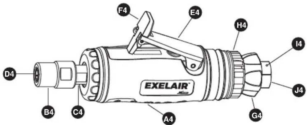
EXELAIR D4 B4 C4 A4 F4 E4 H4 I4 J4 G41/4" AIR DIE GRINDER
| PART | DESCRIPTION | QUANTITY |
| A4 | 1/4" Air Die Grinder | 1 |
| B4 | Collet Jacket | 1 |
| C4 | Collet Holder | 1 |
| D4 | Collet | 1 |
| E4 | Trigger | 1 |
| F4 | Lever | 1 |
| G4 | Air Regulator | 1 |
| H4 | Exhaust Deflector | 1 |
| I4 | Steel Ball Indicator | 1 |
| J4 | Air Inlet | 1 |
50-PIECE COMPOSITE AIR TOOL KIT
1/2" AIR IMPACT WRENCH
| COMPONENT | SPECIFICATIONS |
| Square drive | 1/2" |
| Maximum no load speed | 8,000rpm |
| Maximum torque | 650Ft-Lb (885Nm) |
| Air inlet | 1/4" NPT |
| Air hose (inner diameter) | 3/8" |
| Average air consumption | 6.5cfm |
| Working pressure | 90psi (6.3bar) |
3/8" AIR RATCHET WRENCH
| COMPONENT | SPECIFICATIONS |
| Square drive | 3/8" |
| Maximum no load speed | 180rpm |
| Maximum torque | 60Ft-Lb (85Nm) |
| Air inlet | 1/4" NPT |
| Air hose (inner diameter) | 3/8" |
| Average air consumption | 4cfm |
| Working pressure | 90psi (6.3bar) |
AIR HAMMER
| COMPONENT | SPECIFICATIONS |
| Chisel shank | 0.4" (10.2mm) |
| Stroke length | 1-5/8" (41mm) |
| Blow per min | 4,500bpm |
| Air inlet | 1/4" NPT |
| Air hose (inner diameter) | 3/8" |
| Average air consumption | 5cfm |
| Working pressure | 90psi (6.3bar) |
1/4" AIR DIE GRINDER
| COMPONENT | SPECIFICATIONS |
| Maximum no load speed | 25,000rpm |
| Collet | 1/4" |
| Air inlet | 1/4" NPT |
| Air hose (inner diameter) | 3/8" |
| Average air consumption | 4cfm |
| Working pressure | 90psi (6.3bar) |
ASSEMBLY
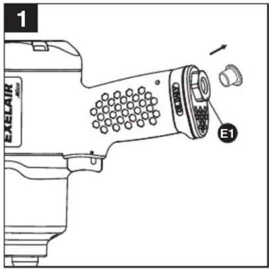
1/2" AIR IMPACT WRENCH
- Remove the air inlet protective cap from the air inlet (E1). (See Figure 1)
text_image
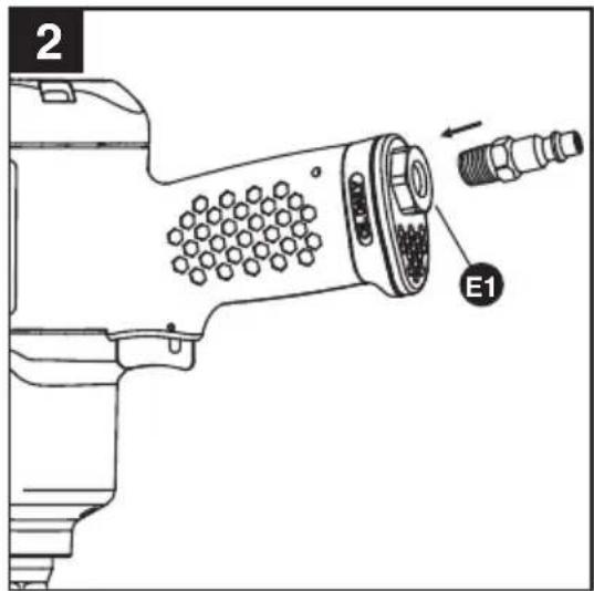
EXELAIR E1- Mount a male plug by hand into the air inlet (E1). (See Figure 2)

NOTE: Use thread sealant tape on the male plug and tighten it with a wrench for airtight connection. Do not overtighten.
text_image
2 E1- Place 2 - 3 drops of air tool oil into the male plug before each use. (See Figure 3)

natural_image
Diagram of a mechanical device with a tool and screw, showing a process step (no text or symbols)- Choose the correct impact socket (J) as needed and mount it onto the anvil (B1). (See Figure 4)

WARNING! Only use impact sockets that have an RPM and Torque rating equal to or greater than the tool itself.

text_image
4 J B1 EXELA OLME12
- If necessary, use the 1/2" extension bar (G) and then mount impact socket onto the bar. (See Figure 5)
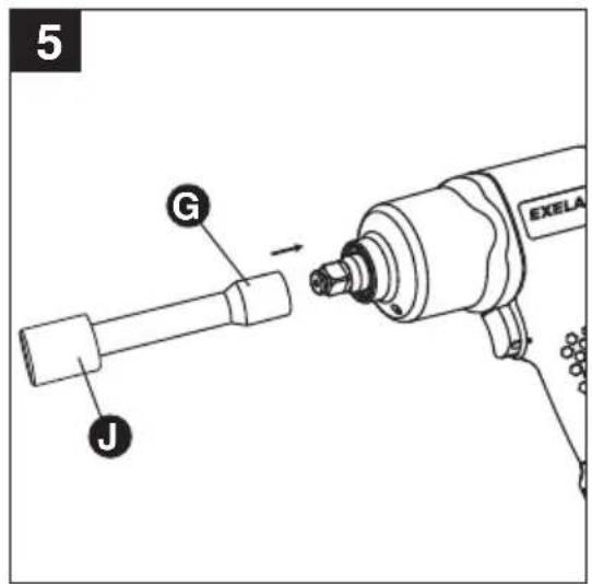
text_image
5 G J EXELA-
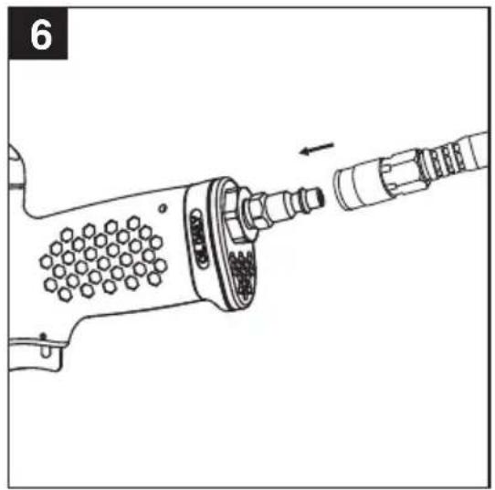
Connect air supply hose to the male plug. (See Figure 6)
-
Set the working pressure at 90psi/6.3bar for best tool performance.

NOTE: Working pressure refers to the air line pressure set to tool when tool is under working conditions.
natural_image
Technical line drawing of a mechanical tool with a bolt and threaded shaft (no text or symbols)50-PIECE COMPOSITE AIR TOOL KIT
3/8" AIR RATCHET WRENCH
- Remove the air inlet protective cap from the air inlet (G2). (See Figure 7)

text_image
7 EXELAIR G213
- Mount a male plug by hand into the air inlet (G2). (See Figure 8)

NOTE: Use thread sealant tape on the male plug and tighten it with a wrench for airtight connection. Do not overtighten.

text_image
8 EXELAIR G2- Place 2 - 3 drops of air tool oil into the male plug before each use. (See Figure 9)

text_image
EXELAIR 950-PIECE COMPOSITE AIR TOOL KIT
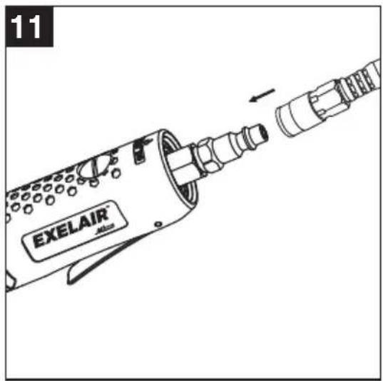
- Apply the 3/8" to 1/2" adaptor (H) to the anvil (B2). Choose the correct impact socket (J) as needed and mount it onto the adaptor (H). (See Figure 10)

WARNING! Only use impact sockets that have an RPM and Torque rating equal to or greater than the tool itself.

text_image
10 J H B2- Connect air supply hose to the male plug. (See Figure 11)
- Set the working pressure at 90psi/6.3bar for best tool performance.

NOTE: Working pressure refers to the air line pressure set to tool when tool is under working conditions.
text_image
11 EXELAIR J9502AIR HAMMER
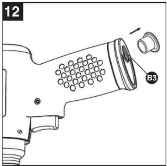
- Remove the air inlet protective cap from the air inlet (B3). (See Figure 12)
text_image
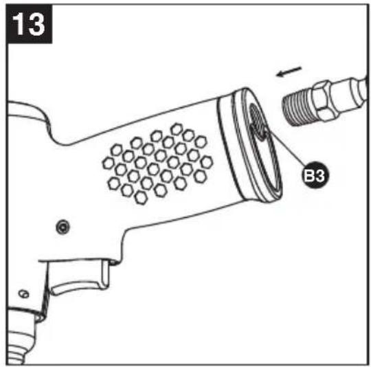
12 B3- Mount a male plug by hand into the air inlet (B3). (See Figure 13)

NOTE: Use thread sealant tape on the male plug and tighten it with a wrench for airtight connection. Do not overtighten.
text_image
13 B315
- Place 2 - 3 drops of air tool oil into the male plug before each use. (See Figure 14)

natural_image
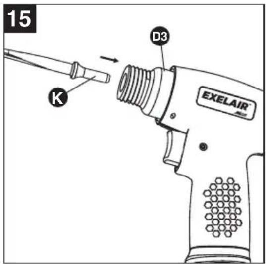
Line drawing of a mechanical tool with a pointed tip and circular components, no text or symbols present- Insert a chisel (K) into the opening of cylinder (D3). (See Figure 15)
text_image
15 K D3 EXELAIR- Screw the spring retainer (F) onto the cylinder (D3) and firmly secure it. (See Figure 16)
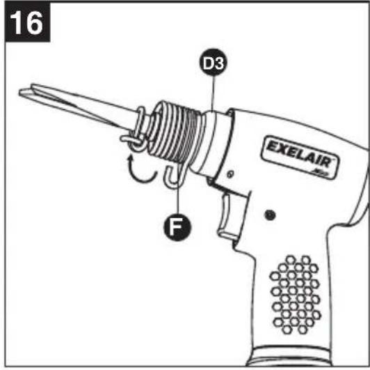
text_image
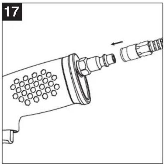
16 D3 EXELAIR F- Connect air supply hose to the male plug. (See Figure 17)
- Set the working pressure at 90psi/6.3bar for best tool performance.

NOTE: Working pressure refers to the air line pressure set to tool when tool is under working conditions.
natural_image
Technical line drawing of a mechanical device with internal components and a directional arrow (no text or symbols)1/4" AIR DIE GRINDER
- Remove the air inlet protective cap from the air inlet (J4). (See Figure 18)

text_image
18 EXELAIR J450-PIECE COMPOSITE AIR TOOL KIT
- Mount a male plug by hand into the air inlet (J4). (See Figure 19)

NOTE: Use thread sealant tape on the male plug and tighten it with a wrench for airtight connection. Do not overtighten.

text_image
19 EXELAIR J417
- Place 2 - 3 drops of air tool oil into the male plug before each use. (See Figure 20)

natural_image
Technical line drawing of a mechanical tool with a pointed tip and threaded end (no text or symbols)- Loosen the collet jacket (B4) counterclockwise by hand or with the large wrench while holding the small wrench on the flats of the collet holder (C4). (See Figure 21)
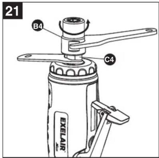
text_image
21 B4 C4 EXELAIR50-PIECE COMPOSITE AIR TOOL KIT
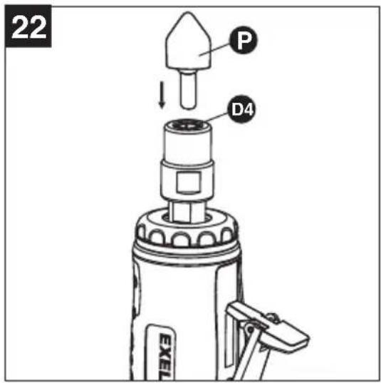
- Insert a grinding stone (P) into the collet (D4). (See Figure 22)
text_image
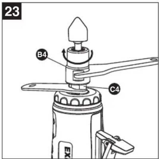
22 P D4 EXEL- Tighten the collet jacket (B4) clockwise with large wrench while holding the small wrench on the flats of the collet holder (C4). Make sure that the grinding stone is installed securely and tightly. (See Figure 23)

WARNING! Only use grinding accessories that have an RPM rating equal to or greater than the tool itself.
text_image
23 B4 C4 EX-
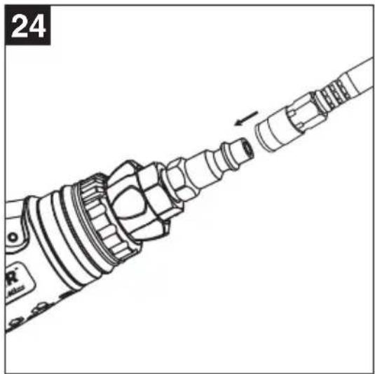
Connect air supply hose to the male plug. (See Figure 24)
-
Set the working pressure at 90psi/6.3bar for best tool performance.

NOTE: Working pressure refers to the air line pressure set to tool when tool is under working conditions.
natural_image
Technical line drawing of a mechanical component with no visible text or symbols50-PIECE COMPOSITE AIR TOOL KIT
OPERATION
1/2" AIR IMPACT WRENCH
- How to install/tighten threaded fasteners. Push the switch (D1) clockwise and have the arrow on the switch (D1) pointing at either of the three dots on the back housing as shown. Press the trigger (C1). The tool anvil (B1) runs clockwise. (See Figure 25)
- How to remove/loosen threaded fasteners. Push the switch (D1) counterclockwise and have thearrow on the switch (D1) pointing at the large dot on the back housing as shown. Press the trigger (C1). The tool anvil (B1) runs counterclockwise. (See Figure 26)

NOTE: This tool features a power regulator valve. Turn the switch (D1) slowly forward until desired output is achieved. The three dots (small, medium, large) do not denote a specific power output but are only for reference. "Setting 1" (small dot) is the least amount of power, which is suitable for just mounting threaded fasteners on workpiece while "Setting 3" (large dot) is the greatest amount of power, which is for tightening threaded fasteners on workpiece. This tool operates in maximum power in reverse, which releases threaded fasteners from workpiece with ease. Choose the correct torque needed on workpiece when mounting or releasing threaded fasteners by understanding the reference torque listed below. (See Figure 27)
| Setting | Torque in Forward | Torque in Reverse |
| 1 | 185 ft-lbs (+/- 10%) | 670 ft-lb (+/- 10%) |
| 2 | 330 ft-lbs (+/- 10%) | |
| 3 | 650 ft-lbs (+/- 10%) |

NOTE: Make sure that this tool has the correct torque to tighten/release threaded fasteners. The torque applied to threaded fasteners can be found in their instructions or manuals.

text_image
25 EXELAIR B1 C1 D1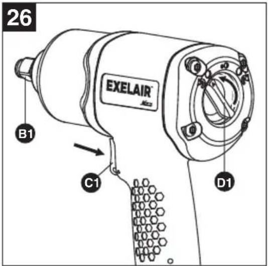
text_image
26 EXELAIR B1 C1 D1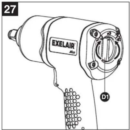
text_image
27 EXELAIR D150-PIECE COMPOSITE AIR TOOL KIT
3/8" AIR RATCHET WRENCH
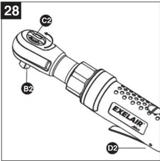
- How to install/tighten threaded fasteners. Turn the F/R knob (C2) counterclockwise to "F" position (F=Forward or Tighten). Press the trigger (D2). The tool anvil (B2) runs clockwise. (See Figure 28)
text_image
28 C2 B2 EXELAIR D220
- How to remove/loosen threaded fasteners. Turn the F/R knob (C2) clockwise to "R" position (R=Reverse or Loosen). Press the trigger (D2). The tool anvil (B2) runs counterclockwise. (See Figure 29)

text_image
29 C2 B2 EXELAIR D2AIR HAMMER
- Hold the tool firmly with both hands. Bring the tool towards the workpiece at an angle of 60-70 degrees approximately.
- Press the trigger (C3) slowly with the chisel in light contact with the workpiece. (See Figure 30)
- Slowly move the chisel across the workpiece surface.

NOTE: When removing scale, rust or other contaminants, you only need to apply a light force on the tool.

text_image
30 EXELAIR C3
NOTE: Keep the chisel contacting the workpiece while you are releasing the trigger to stop operation. The tool may impact briefly after the trigger is released.
50-PIECE COMPOSITE AIR TOOL KIT
1/4" AIR DIE GRINDER
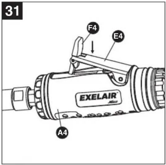
Push lever (F4) forward and press down on the trigger (E4) to start the tool (A4). (See Figure 31)
text_image
31 F4 E4 EXELAIR A4
NOTE: This tool features a power regulator valve. Rotate the air regulator (G4) until desired output is achieved. The settings 1, 2, 3, 4 are only for reference and do not denote a specific power output. "Setting 1" is the lowest speed while "Setting 4" is the highest speed. Rotate the air regulator (G4) until the desired setting is lined up with the small steel ball (I4) on air inlet (J4). (See Figure 32)

text_image
32 J4 I4 G4 AIR Mixer
NOTE: This tool also features an exhaust deflector (H4) which is rotatable to direct air away in any direction. (See Figure 33)

text_image
33 AIR H450-PIECE COMPOSITE AIR TOOL KIT
| PROBLEM | CORRECTIVE ACTIONPOSSIBLE CAU | |
| Tool runs slowly or will not operate | 1. Grit or gum in tool.2. No oil in tool.3. Low air pressure.4. Air hose leaks.5. Pressure drops.6. Worn rotor blade.7. Moisture blowing out of tool exhaust. | 1. Flush the tool with air-tool oil or gum solvent.2. Lubricate the tool.3. a. Adjust the regulator on the tool to maximum setting.b. Adjust the compressor regulator to tool maximum of 90 PSI/6.3 BAR.4. Tighten and seal hose fittings if leaks are found. Use sealing tape.5. a. Be sure the hose is the proper size. Long hose or tools using large volumes of air may require a hose with an I.D. of 1/2 in. or larger depending on the total length of the hoses.b. Do not use a multiple number of hoses connected together with quick-connect fittings. This causes additional pressure drops and reduces the tool power. Directly connect the hoses together.6. Replace rotor blade.7. Water in tank; drain tank. (See air compressor manual). Oil tool and run until no water is evident. Oil tool again and run 1-2 seconds. |
CARE AND MAINTENANCE
An in-line oiler is recommended to be installed on air supply line as it increases tool life and keeps the tool in sustained operation. The in-line oiler should be regularly checked and filled with air-tool oil. Proper adjustment of the in-line oiler is performed by placing a sheet of paper next to the tool's exhaust ports and holding the throttle open approximately 30 seconds. The in-line oiler is properly set when a light stain of oil collects on the paper. Excessive amounts of oil should be avoided.
In the event that it becomes necessary to store the tool for an extended period of time, it should receive a generous amount of lubrication at that time. The tool should be run for approximately 30 seconds to ensure oil has been evenly distributed throughout the tool. The tool should be stored in a clean and dry environment.
Recommended lubricants: use air-tool oil or any other high-grade turbine oil containing moisture absorbent, rust inhibitors, metal wetting agents and an EP (extreme pressure) additive.
Clean the tool all over with a cotton rag after each use. Keep the tool in a dry and safe place out of reach of children.
1/2" AIR IMPACT WRENCH
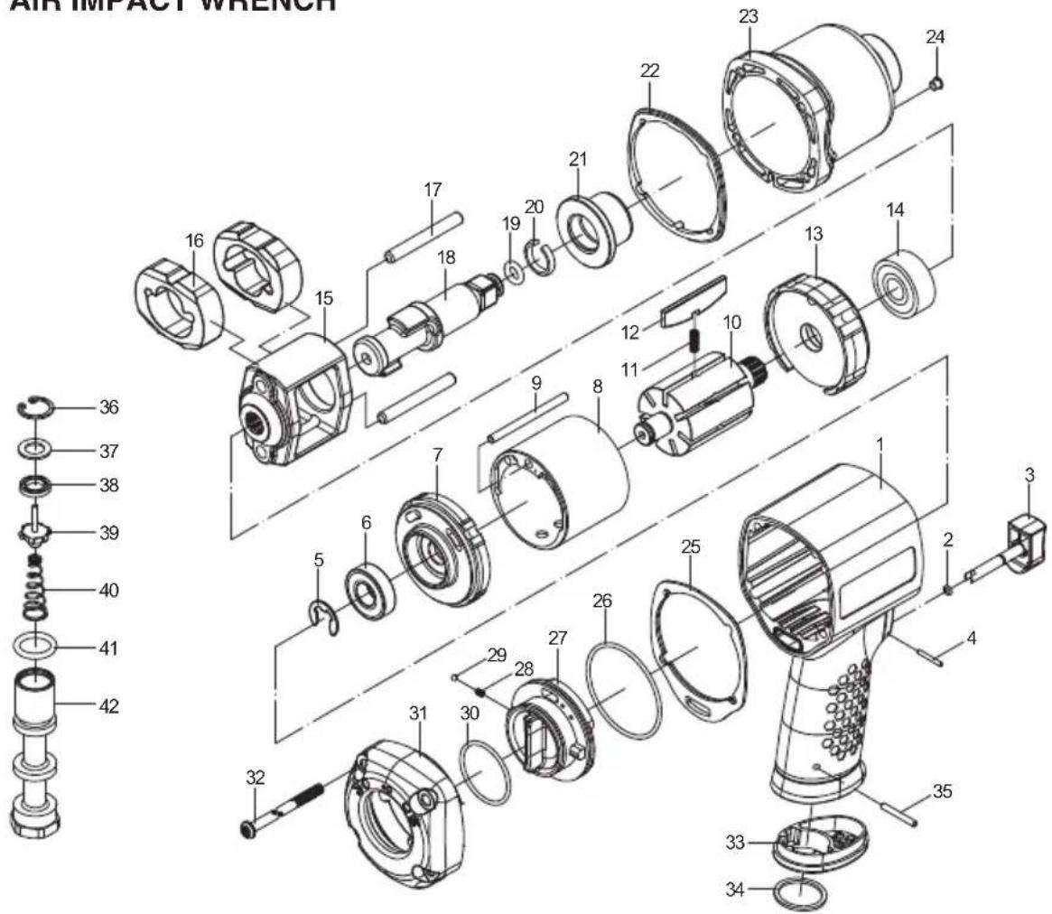
text_image
AIR IMPACT WRENCH 36 37 38 39 40 41 42 16 15 17 18 19 20 21 22 23 24 13 14 12 11 10 9 8 7 6 5 32 31 30 29 28 27 26 25 24 23 22 21 17 16| Part No. | Description | Qty. |
| 1 | Main housing* | 1 |
| 2 | O-ring - EX1265CIW-02 | 1 |
| 3 | Trigger - EX1265CIW-03 | 1 |
| 4 | Bolt* | 1 |
| 5 | E-ring* | 1 |
| 6 | Bearing* | 1 |
| 7 | Rear plate* | 1 |
| 8 | Cylinder* | 1 |
| 9 | Bolt* | 1 |
| 10 | Rotor* | 1 |
| 11 | Spring - EX1265CIW-11 | 7 |
| 12 | Rotor blade - EX1265CIW-12 | 7 |
| 13 | Front plate* | 1 |
| 14 | Bearing* | 1 |
| 15 | Hammer cage* | 1 |
| 16 | Hammer dog* | 2 |
| 17 | Hammer pin* | 2 |
| 18 | Anvil* | 1 |
| 19 | O-ring - EX1265CIW-19 | 1 |
| 20 | Retainer ring* | 1 |
| 21 | Bushing* | 1 |
| Part No. | Description | Qty. |
| 22 | Gasket* | 1 |
| 23 | Front housing* | 1 |
| 24 | Grease cap* | 1 |
| 25 | Gasket* | 1 |
| 26 | O-ring - EX1265CIW-26 | 1 |
| 27 | Switch* | 1 |
| 28 | Spring* | 1 |
| 29 | Steel ball* | 1 |
| 30 | O-ring - EX1265CIW-30 | 1 |
| 31 | Rear cover* | 1 |
| 32 | Set screw* | 4 |
| 33 | Exhaust deflector* | 1 |
| 34 | Cushion* | 1 |
| 35 | Bolt* | 1 |
| 36 | Circlip* | 1 |
| 37 | Spacer* | 1 |
| 38 | Oil seal* | 1 |
| 39 | Tilt valve* | 1 |
| 40 | Spring* | 1 |
| 41 | O-ring - EX1265CIW-41 | 1 |
| 42 | Air inlet* | 1 |
*Replacement part not available
50-PIECE COMPOSITE AIR TOOL KIT
3/8" AIR RATCHET WRENCH
text_image
Exploded view diagram of a portable flashlight with numbered parts for identification| Part No. | Description | Qty. |
| 1 | Main housing* | 1 |
| 2 | Housing liner* | 1 |
| 3 | Trigger - EX3860CAR1-03 | 1 |
| 4 | Bolt* | 1 |
| 5 | O-ring - EX3860CAR1-05 | 1 |
| 6 | Bushing* | 1 |
| 7 | O-ring - EX3860CAR1-07 | 1 |
| 8 | Valve stem* | 1 |
| 9 | Spring* | 1 |
| 10 | O-ring - EX3860CAR1-10 | 1 |
| 11 | Screw* | 1 |
| 12 | Nipple* | 1 |
| 13 | Exhaust deflector* | 1 |
| 14 | Air inlet* | 1 |
| 15 | Decoration ring* | 1 |
| 16 | Bearing* | 1 |
| 17 | Rear plate* | 1 |
| 18 | Rotor* | 1 |
| 19 | Rotor blade - EX3860AR1-26 | 4 |
| 20 | Cylinder* | 1 |
| 21 | Set pin* | 3 |
| 22 | Front plate* | 1 |
| 23 | Bearing* | 1 |
| 24 | Cushion* | 1 |
| Part No. | Description | Qty. |
| 25 | Ring gear* | 1 |
| 26 | Gear* | 3 |
| 27 | Gear pin* | 3 |
| 28 | Gear seat* | 1 |
| 29 | Screw nut* | 1 |
| 30 | Needle bearing* | 1 |
| 31 | Bushing* | 1 |
| 32 | Eccentric shaft* | 1 |
| 33 | Drive bushing* | 1 |
| 34 | Ratchet housing* | 1 |
| 35 | Ratchet yoke* | 1 |
| 36 | F/R knob* | 1 |
| 37 | Sleeve* | 2 |
| 38 | Spring* | 2 |
| 39 | Washer* | 1 |
| 40 | Ratchet head* | 1 |
| 41 | Pin* | 2 |
| 42 | Ratchet pawl* | 2 |
| 43 | Washer* | 1 |
| 44 | Circlip* | 1 |
| 45 | Spring* | 1 |
| 46 | Steel ball* | 1 |
| 47 | Spring* | 2 |
| 48 | Steel ball* | 2 |
*Replacement part not available
50-PIECE COMPOSITE AIR TOOL KIT
EXPLODED DIAGRAM AND PARTS LIST
AIR HAMMER
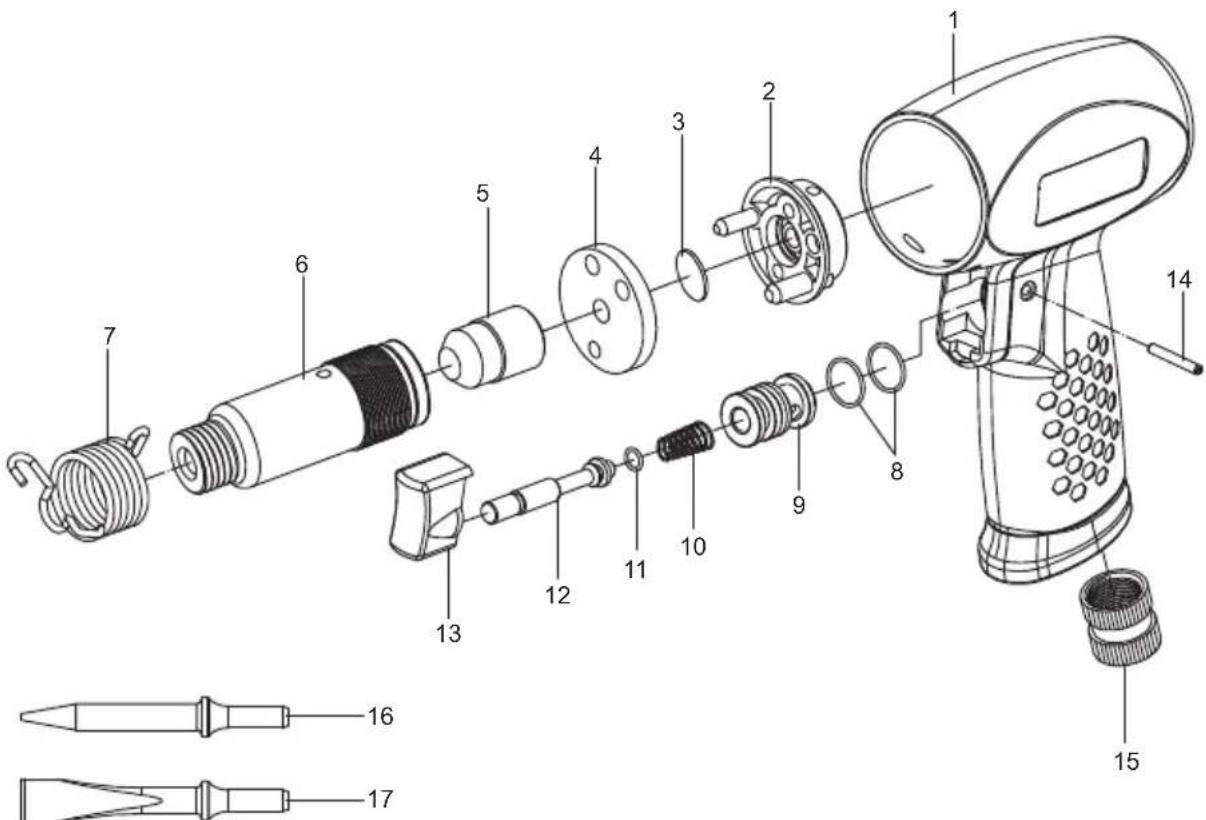
text_image
Exploded view diagram of a mechanical device with numbered parts for identification| Part No. | Description | Qty. |
| 1 | Main housing* | 1 |
| 2 | Valve seat* | 1 |
| 3 | Valve plate* | 1 |
| 4 | End cap* | 1 |
| 5 | Piston* | 1 |
| 6 | Cylinder* | 1 |
| 7 | Retainer spring* | 1 |
| 8 | O-ring - EX3860CAR1-10 | 2 |
| 9 | Valve sleeve* | 1 |
| Part No. | Description | Qty. |
| 10 | Spring* | 1 |
| 11 | O-ring - EX3860CAR1-07 | 1 |
| 12 | Valve stem* | 1 |
| 13 | Trigger - EX0445CAH1-13 | 1 |
| 14 | Set pin* | 1 |
| 15 | Air inlet* | 1 |
| 16 | Chisel* | 1 |
| 17 | Chisel* | 1 |
*Replacement part not available
50-PIECE COMPOSITE AIR TOOL KIT
1/4" AIR DIE GRINDER
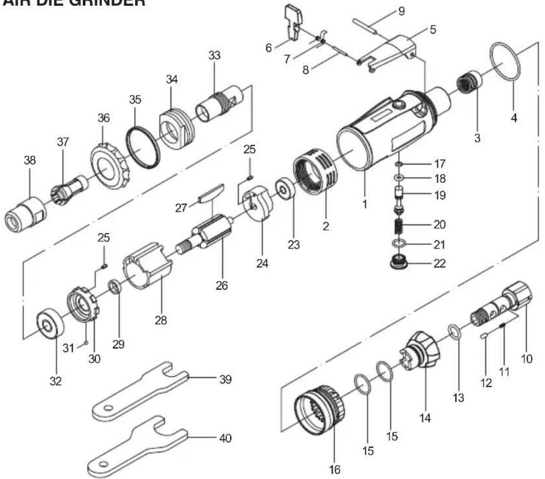
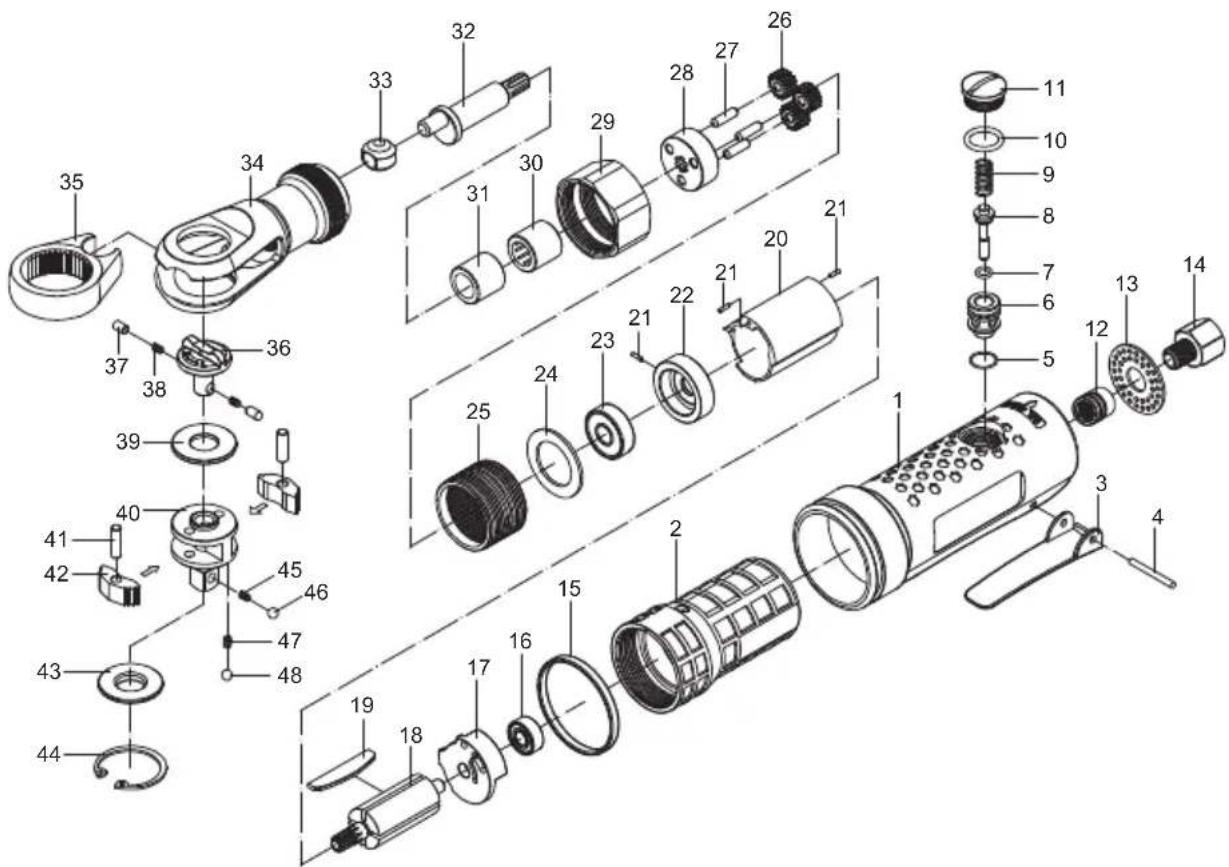
text_image
AIR DIE GRINDER 38 37 36 35 34 33 25 27 26 24 23 1 9 7 8 5 4 3 17 18 19 20 21 22 31 30 29 28 39 32 40 16 15 15 14 13 12 11 10| Part No. | Description | Qty. |
| 1 | Main housing* | 1 |
| 2 | Housing liner* | 1 |
| 3 | Bushing* | 1 |
| 4 | O-ring - EX1425CDG1-04 | 1 |
| 5 | Trigger - EX1425CDG1-05 | 1 |
| 6 | Lever* | 1 |
| 7 | Spring* | 1 |
| 8 | Bolt* | 1 |
| 9 | Trigger pin* | 1 |
| 10 | Air inlet* | 1 |
| 11 | Spring* | 1 |
| 12 | Pin* | 1 |
| 13 | O-ring - EX1425CDG1-13 | 1 |
| 14 | Air regulator* | 1 |
| 15 | O-ring - EX1425CDG1-15 | 2 |
| 16 | Exhaust deflector* | 1 |
| 17 | O-ring - EX1425DG1-08 | 1 |
| 18 | O-ring - EX3860CAR1-07 | 1 |
| 19 | Valve stem* | 1 |
| 20 | Spring* | 1 |
| Part No. | Description | Qty. |
| 21 | O-ring - EX1425CDG1-21 | 1 |
| 22 | Screw* | 1 |
| 23 | Bearing* | 1 |
| 24 | Rear plate* | 1 |
| 25 | Set pin* | 2 |
| 26 | Rotor* | 1 |
| 27 | Rotor blade - EX1425DG1-30 | 4 |
| 28 | Cylinder* | 1 |
| 29 | Bushing* | 1 |
| 30 | Front plate* | 1 |
| 31 | Steel ball* | 1 |
| 32 | Bearing* | 1 |
| 33 | Collet seat* | 1 |
| 34 | Lock ring* | 1 |
| 35 | Decoration ring* | 1 |
| 36 | Front protection cover* | 1 |
| 37 | Collet* | 1 |
| 38 | Collet jacket* | 1 |
| 39 | Small wrench* | 1 |
| 40 | Large wrench* | 1 |
*Replacement part not available
50-PIECE COMPOSITE AIR TOOL KIT
50-PIECE COMPOSITE AIR TOOL KIT
EXELAIR™
MILTON INDUSTRIES AIR TOOL WARRANTY POLICY
3 YEAR LIMITED WARRANTY
Please visit www.miltonindustries.com to register this product for the 3-Year limited warranty offered by Milton.
To make any warranty claims or to learn more about the 3 year warranty please visit www.miltonindustries.com


For questions about our warranty on this product, contact us at:
MILTON INDUSTRIES, INC.
4500 W. CORTLAND STREET,
CHICAGO, IL 60639
Phone: 855-G04-MILT (855-464-6458)
www.exel-air.com