HCB90SDSS - Cooker ILVE - Free user manual and instructions
Find the device manual for free HCB90SDSS ILVE in PDF.

User questions about HCB90SDSS ILVE
0 question about this device. Answer the ones you know or ask your own.
Ask a new question about this device
Download the instructions for your Cooker in PDF format for free! Find your manual HCB90SDSS - ILVE and take your electronic device back in hand. On this page are published all the documents necessary for the use of your device. HCB90SDSS by ILVE.
USER MANUAL HCB90SDSS ILVE
USER, OPERATING & INSTALLATION MANUAL
PRO-LINE, PROFESSIONAL PLUS & NOSTALGIE BUILT-IN COOKTOPS
(ALL COOKTOP TYPES)

KITCHEN APPLANCES HANDMADE IN ITALY
Congratulations, you are now the proud owner of an ILVE cooking appliance. Thank you for purchasing ILVE and welcome to the exciting world of cooking the ILVE way.
This instruction manual has been specially created to inform you of the full range of features your ILVE appliance has to offer and serves as an introduction to the wonderful benefits of ILVE's dynamic cooking systems.
We present detailed information on each of the advanced cooking systems built into ILVE appliances. Once you have read this section you will be able to choose the most appropriate settings for your appliance when cooking different types of food.
We ask you to read the instructions in this booklet very carefully as this will allow you to get the best results from using your appliance.
KEEP THE DOCUMENTATION OF THIS PRODUCT FOR FUTURE REFERENCE.
YOUR FREE MASTERCLASS
Although we encourage you to dive right in, as the owner of a brand new ILVE oven we'd also like to invite you to attend a complimentary 2 hour masterclass. As part of the class you'll learn how to prepare and cook a number of delicious signature ILVE dishes, not to mention our top tips for getting the meat out of your ILVE oven. From improving cooking results to general maintenance information, we know you'll enjoy this comprehensive, fun masterclass.
Simply go to ilve.com.au/bookings or Phone 1300 MY ILVE (694 583)
ilve.com.au

natural_image
Roasted meat dish served on a square white plate with blue trim, being placed on a gas stove (no text or symbols visible)

natural_image
Laptop screen displaying various kitchen utensils including wooden tray, rectangular bins, and a film reel (no text or symbols visible)OPEN 24/7
ILVE ACCESSORIES ONLINE SHOP
For a wide range of Genuine ILVE accessories at the click of a button go to ilve.com.au
CONTENTS
4 IMPORTANT SAFETY WARNINGS
11 INSTRUCTIONS FOR USE
11 Use of the cooking hob
13 Correct use of burners
15 Correct use of the grills
18 Use of the gas fry-top
20 Use of the gas barbeque (optional)
21 CLEANING AND MAINTENANCE
21 Cleaning the appliance
22 Total black burners
23 INSTALLATION
23 Instructions
24 Built-in installation
25 Built-in tops' hole size
28 Electric connection
29 Gas connection and transformation
31 Adjustment and/or adapting to different types of gas
32 Gas regulation
33 Gas jets adjustment table
34 Replacement of the injectors
35 Cooking hob table
36 Adjustment of minimum
37 WIRING DIAGRAMS
37 Keys
39 TROUBLESHOOTING
39 Troubleshooting Guide
41 NOTES
OPERATION / USER
IMPORTANT SAFETY WARNINGS

Appliances' data
The data plate, as well as being on the cover, is also on the a pliance.
CAUTION
1 These warnings refer to different appliance models. Be sure that you have correctly identified the model that you possess (see the data plate).

These warnings are valid for the countries listed on the plate.
2 Read the instructions booklet carefully, before using the appliance. This contains very important informations concerning safety during installation, use and maintenance. The instructions booklet must be kept with care for later consultation and for the identification of the serial number.
3 The electrical safety of this appliance is only guaranteed if it is properly earthed as required by the regulations in force. It is fundamental to ensure that these regulations have been respected; if you are in doubt, call a skilled technician to have the electrical system checked in detail. The manufacturer does not accept any responsibility for damage caused by a bad earthing system.
4 Before connecting the cooker, check that the technical features on the data plate correspond perfectly with those of the electric system and of the gas mains. The installation / regulation must be made by qualified staff.
5 Check that air circulates freely around the appliance. This appliance is not connected to a combustion products evacuation device therefore the premises' ventilation system must be considered carefully and according to the rules in force.
i ILVE
IMPORTANT SAFETY WARNINGS

6 When using gas appliances, heat and dampness are generated inside the premises. Good ventilation of the kitchen is required by: keeping the natural vents open or installing a mechanical ventilator (hood). Intensive and prolonged use of the appliance can make supplementary ventilation necessary: opening a window or increasing the power of the hood.
7 The power cable is supplied without a plug. To connect please refer to the "electric connection" paragraph. We advise not using adapters, multiple sockets or extensions.
8 Disconnect the power supply when the appliance is not used for some time, switch off the mains and turn off the gas.
9 When the electric cable is damaged, it must be replaced by calling an after saves service approved by the manufacturer.
10 The appliance must only be used for the purposes for which it was intended (cooking). Any other use (for example, heating a room) is incorrect and therefore dangerous. The manufacturer declines all responsibility for damage caused by similar incorrect uses.
The unit is not intended to be operated by an external timer or a separate remote control system.
11 The use of any electrical appliance requires that the following rules are respected:
A. never touch the appliance when you have wet or damp hands or feet;
B. never use the appliance in your bare feet;
OPERATION / USER
IMPORTANT SAFETY WARNINGS

C. avoid using extensions or, if this is inevitable, take all possible precautions;
D. Never pull on the electric cable to remove it from the power socket;
E. do not expose the appliance to weathering (rain, sun, etc.);
F. Be careful: the accessible parts may become very hot during use. Keep children less than 8 years old away from the cooker, if not continuously supervised. This appliance can be used by children from 8 years old and by persons with reduced physical, sensory or mental abilities otherwise with lack of experience and knowledge if they are adequately supervised or if they have been instructed on the safe use of the cooker and if they realise the relevant dangers. Children must not play with the cooker. Cleaning and maintenance must not be done by unsupervised children.
12 BE CAREFUL: some accessible parts may have high temperatures during use; keep children at a distance.
13 Before cleaning the appliance or carrying out maintenance, disconnect the power supply by removing the plug from the socket or switching the current off through the switch provided. In the event of faults or malfunctions, switch off the appliance, turn off the gas tap and do not attempt to make any repairs; these must be carried out exclusively by an approved service centre. Always insist on original spare parts. Failure to follow these indications may endanger the safety of the cooker.
IMPORTANT SAFETY WARNINGS

14 Never place unsteady or deformed pans on the burners or on the electric hotplates as they could overturn accidentally.
When the appliance is not in use, ensure that all the knobs are in the “●”/“○”/OFF position.
15 Never leave the hotplate switched on without a pan on it, otherwise it will reach a very high temperature quickly and the cooker or furniture in the vicinity could be damaged.
16 Some parts of the cooker, especially the electric hotplates, stay warm for a long time after use. Be careful not to touch them.
17 Do not keep below the cooker and do not use inflammable liquids (detergents, sprays, alcohol, petrol ...) near the cooker when it is switched on.
18 If using small electric appliances near the hob, be sure to prevent the electric cable from touching the appliance's hot parts.
19 In order to work properly, gas cookers must be installed in well ventilated premises. Ensure that installation is carried out according to the indications given in the "Installation" chapter.
20 The materials used in the construction of our electrical appliance are compatible with the environment and therefore recyclable. Packaging remains should not be left within the reach of children, but disposed of using specific recycling channels. The possibility of disposing of your equipment through your local retailer and/or town council should be investigated; remember to make your appliance unusable before scrapping it.
OPERATION / USER
IMPORTANT SAFETY WARNINGS


21 In case the tap is hard or precarious to turn, do not intervene on the tap but shut off the gas and have the authorised service centre intervene.
Do not modify or change the cooker.
22 Be careful: leaving the unguarded cooker with objects, fats and oils can be dangerous and can cause a fire.
23 The cooker must be used by responsible people. Be careful: the use of inappropriate or unsuitable protections can cause fires and / or damage.
24 Be careful: cooking with fat or oil can be dangerous or cause fires.
25 Be careful: fire danger: do not keep objects on cooking surfaces.
26 Be careful: in the case of fire never attempt to extinguish a flame / fire with water, but turn the appliance off and cover the flame with a lid or with a fireproof cover.
27 Be careful: metal objects such as knives, forks, spoons or lids should not be placed on the cooker because they can get hot.
28 Be careful: do not use gas burners if the flame is unstable.
29 Ensure that the flame diffusers are properly positioned in their seats with their respective caps.
30 Do not leave the cooker unguarded during any cooking that can spit fats or oils.
31 Do not touch the appliance's heating elements when on. Let them cool before proceeding with any cleaning.
IMPORTANT SAFETY WARNINGS

32 Food preparation in plastic or aluminium containers on hot cooking zones is forbidden just like the positioning on the cooking surfaces of plastic or aluminium foil objects.
33 Do not cover the burners or the hob with tinfoil.
34 Do not use the appliance's surface as a work top, sharp objects might scratch it.
35 Containers or grills must be positioned within the hob's perimeter.
36 Be careful: do not use frying pans, saucepans, grills or stones for grilling of a greater size than the maximum ones indicated for each single burner; above all they must not cover more than one burner at the same time. The heat accumulation might damage the cooker.
37 In case of liquid spilling over, remove it from the hob.
38 Do not place empty saucepans on the cooking areas.
OPERATION / USER
INSTRUCTIONS FOR USE Use of the cooking hob
WARNING
Keep children and the disabled away during operation. Do not use the appliance as a heating source.
General notes
To keep the appliance efficient and safe, maintenance must be entrusted to specialised technicians or to the after-sales service staff. Choose covered pans based on the quantity of food to cook.
IMPORTANT
text_image
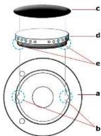
c d e a b
text_image
b c d aPosition the brass flame distributor "d" (fig C) properly. For this, line up the tooth "e" on the flame distributor with thw hollow "b" of the aluminium cup "a".
Position the brass flamee distributor "b" properly. For this, line up the tooth "c" on the flame distributor with the hollow "d" of the aluminium cup "a".
Lighting the burners
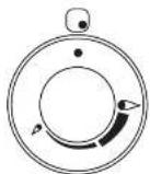
The index above the knobs fig.12a will help you to find the corresponding burner. Press the knob by turning it anticlockwise and bring it to the ignition position; keep the knob pressed for about 5 seconds so that upon its release the flame remains alight (in case of unsuccessful ignition repeat the operation).
Symbols

Function
Off
Maximum
Minimum
Index

INSTRUCTIONS FOR USE
Use of the cooking hob
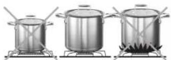
Pots to be used according to the size of the burners
natural_image
Three identical cooking pots on stoveters with steam rising (no text or symbols visible)| Burners ID Diameter ∅ (cm) | |
| Medium SR 10/20 | |
| Large R 20/24 | |
| Fish burner P oven pans | |
| Ring TC/DCC 22/28 | |
| Dual ring DUAL 24/30 | |
Igniting the Triple ring burner "DUAL"
Identify the knob with the help of the index placed at the knobs themselves. Press and turn the knob to the (maximum) symbol for 5 seconds. Once the burner is on, continuing to turn the knob anticlockwise leads to a first block of the knob that corresponds to the medium. Applying a slight force the first block is exceeded and the outer crown turns off leaving only the small central burner called AUXILIARY. To adjust the auxiliary burner to minimum, turn the knob anticlockwise until it stops. At this point, to turn the burner back on, turn the knob clockwise to the desired value.
Dual knob
Symbols
Function

Off
Maximum
Minimum
Index


i ILVE
14 15
OPERATION / USER
INSTRUCTIONS FOR USE
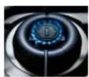
Correct use of burners
Placement of the burners
BE CAREFUL: always check that the burners are correctly positioned, thus having a homogeneous and not noisy flame.
Burners
Right
Wrong
Medium

natural_image
Close-up of a black circular object mounted on a metallic base, with no visible text or symbols.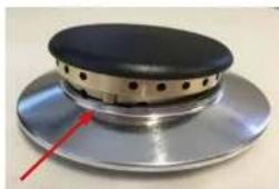
natural_image
Close-up of a metallic mechanical component with a circular top and central slot, marked by a red arrow (no text or symbols visible)Large

natural_image
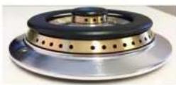
Top-down view of a black circular object with perforated lid, placed on a silver plate (no text or symbols visible)
natural_image
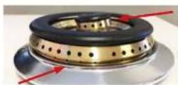
Close-up of a metallic circular object with perforated top and a red arrow pointing to its side (no text or symbols visible)Dual ring
Fish burner

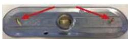
Always check that the screws below the burner are fixed.
i ILVE
INSTRUCTIONS FOR USE
Correct use of burners
| Positioning of the burners | BE CAREFUL: always check that the burners are correctly positioned, thus having a homogeneous and not noisy flame. | |
| Burners | Right Wrong | |
| Medium |  |  |
| Large | 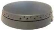 |  |
| Dual ring |  | 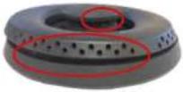 |
| Fish burner | 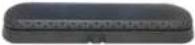 | 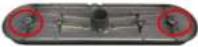 |
Always check that the screws below the burner are fixed.
OPERATION / USER
INSTRUCTIONS FOR USE
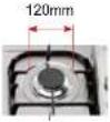
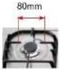
Correct use of the grills
| Placement of the grills | BE CAREFUL: always check that the grills are properly positioned and facing the right way. | |||
| Internal grills hole measurement | FISH BURNERS RING (DUAL) LARGE MEDIUM | |||
 |  |  |  | |
| Different types of grills |  | 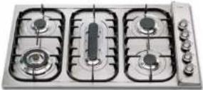 | ||
| H30 | H38P | |||
 |  | |||
| H30C | H90CC | |||
INSTRUCTIONS FOR USE
Correct use of the grills

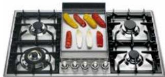
HP65
natural_image
Front view of a four-gas stove with visible flames and control knobs (no text or symbols)H70

HF40
H90P

HF40D

H906
HP45F

HP95P
i ILVE
18 19
OPERATION / USER
INSTRUCTIONS FOR USE
Correct use of the grills
natural_image
Modern gas stove with four fans and a side dish of colorful food items (no visible text or symbols)HP95F
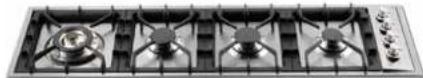
HP1230
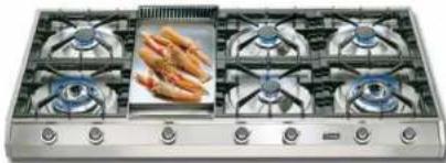
natural_image
Six identical stainless steel gas stove units with six fans and one open showing fried food (no visible text or symbols)HP1265
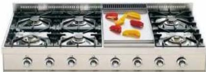
natural_image
Front view of a stainless steel double boiler with multiple gas flares and a central dish (no visible text or symbols)HP120
i ILVE
INSTRUCTIONS FOR USE
Use of the gas fry-top
Instructions
The fry top consists of a stainless steel plate, suitable for contact with food [icon] with a uniform temperature of the cooking surface and with a very low heat dispersion.
To use the appliance, light the flame underneath the plate by turning the corresponding knob (see "Burner ignition") and make sure the flame is present.
Position the knob at the maximum for about 10 minutes and wait for the plate to heat up. After this period of time, the plate is ready to start cooking.
By adjusting the flame, you will have no limit to your culinary imagination.
The position of the knob on the minimum allows slow or dietetic cooking while, for cooking meat, fish and vegetables, faster cooking is indicated. The fry top plate is also suitable for oriental dishes with an optional (lid) necessary for this type of cooking.
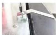
Some models are supplied with a spatula (pic. 2) that will help you cooking and cleaning the plate.
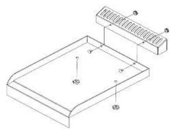
natural_image
Isometric technical drawing of a rectangular enclosure with labeled components (no text or symbols present)
text_image
B A CA = cooking area
B = drip tray
C = exhaust flue for combustion flame
i ILVE
20 21
OPERATION / USER
INSTRUCTIONS FOR USE
Use of the gas fry-top
Pic. 1
A = Max
B = Med
C = Min
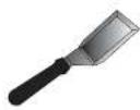
Pic. 2
| Dish Knob posit. (pic.1) Time min. | ||
| Eggs B 2 | ||
| Sliced aubergines(0.5 cm thick) | B 9/13 | |
| Sliced potatoes B 5/7 | ||
| Sliced courgettes B 3/5 | ||
| Fish (sea bream weighingabout 200 g) | B | 15 |
| Hamburger | B | 10 |
| Beefsteak | B 3 | |
| Porterhouse (2 cm thick) A 5 |
Cleaning and care of the Fry-Top
It is recommended to clean the plate thoroughly at the end of each coking session. With the plate hot and the flame at minimum, remove the cooking residue using the scraper provided (pic. 2). Pour a little water onto the plate and, still using the scraper, continue cleaning the plate. Once the water has completely evaporated, repeat the same operation even several times until the desired result is obtained. It is extremely important to clean the plate when it is quite hot.
The black enamel flue may be cleaned with a soft cloth soaked with a solution of lukewarm water and ammonia. Rinse and dry after cleaning.
i ILVE
INSTRUCTIONS FOR USE
Use of the gas barbeque (optional)
Instructions
Replace the flame spreader A with the flame spreader protected for barbecue B. Before refitting the barbecue plate, make sure you have positioned the flame spreader correctly and carry out an ignition test.
To use the appliance, light the flame underneath the plate by turning the corresponding knob (see "Burner ignition") and make sure the flame is present. Position the knob at the maximum for about 10 minutes and wait for the plate to heat up. After this period of time, the plate is ready to start cooking. Place the burner at minimum and place the dishes on the plate. Consult the cooking table for general information on timing. You may find cooking times different from those shown in the table. This is completely normal, as times change according to the quantity and temperature of the food, the type of gas and, of course, your personal taste.
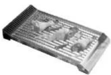

text_image
Technical diagram showing a 3D layout with labeled components A, B and directional arrows indicating flow or movement.Barbeque cleaning
Allow the barbecue to cool before cleaning. Use a slightly abrasive sponge or a brush with brass bristles following the satin finish of the plate. It is important to remove the incrustations that form between one lamella and the other. It is advisable to clean the plate after each cooking. Like all barbecues, the plate with use loses its brilliance and can create dark halos. Once cooled, the fireplace is cleaned with a soft cloth soaked in a solution of warm water and ammonia.
| Dish Knob posit. | (pic.1) Time min. | |
| Sliced auberginos (0.5 cm thick) | B 3/15 | |
| Sliced potatoes B 5/7 | ||
| Sliced courgettes B 4/6 | ||
| Fish (sea bream weighing about 200 g.) | A | 10 |
| Hamburgher A 10 | ||
| Beefsteak | B | 3 |
i ILVE
22 23
OPERATION / USER
CLEANING AND MAINTENANCE
Cleaning the appliance
Warning

Before carrying out any cleaning operation, disconnect the appliance from the power supply and close the general gas cock to the appliance. Cleaning the worktop: clean the hob only after cooling. Periodically the burner cups, the enamelled grills, the enameled lids, and the flame spreader must be cleaned with lukewarm soapy water, rinsed and dried well. Any liquid overflowing from the pans must always be removed with a rag. Cleaning the enamelled parts: To maintain the characteristics of the enamelled parts, it is necessary to clean them frequently with soapy water. Never use abrasive powders or metal pads. Avoid leaving acid or alkaline substances (vinegar, lemon juice, salt, tomato juice, etc.) on the enamelled parts and wash when the enamelled parts are still hot.
Cleaning of stainless steel parts
Clean the parts with warm water and non-corrosive liquid detergent and then dry them with a soft cloth or microfibre. The brilliance is maintained by periodic cleaning with special products normally available on the market. Never use abrasive powders.
Food stains or residues
Absolutely avoid using steel sponges and sharp scrapers to avoid damaging the surfaces. Use normal, non-abrasive products, possibly with the aid of wooden or plastic tools. Rinse thoroughly and dry with a soft cloth or a microfibre cloth. Avoid leaving residues of sugary food (such as jam) inside the appliance as they could damage the enamel in the appliance.
Cooking hob grills

Remove the grids and clean them in warm water and a non-abrasive detergent. Carefully remove any encrustations. Dry them and place them on the hob. The continuous contact of the grids with the flame can cause an alteration of the enamel in the vicinity of the areas exposed to heat. This is a completely natural phenomenon that does not affect the functionality of this component at all.
Ignitors and thermocouples
For good operation, the ignition plugs and thermocouples must always be well cleaned. Check them frequently and if necessary clean them with a damp cloth. Any dry residues must be removed with a wooden toothpick or a needle.
Flame distributor rings and covers

The flame-spreader crowns and the lids are removable for easy cleaning. Wash them in hot water and non-abrasive detergent. Carefully remove any encrustations and wait until they are perfectly dry.
In the event of a malfunction, make sure that the holes in the outer crown are always perfectly clean.
The use of the dishwasher for cleaning grills, flame spreaders and lids is not recommended
i ILVE
CLEANING AND MAINTENANCE
Total black burners
Total black burners coated with treatment nanotechnology
In order to preserve the quality of the coating, some cleaning and washing methods are recommended:
- Allow the product to cool to room temperature before cleaning. It is advisable not to immerse it in cold water when it is still hot.
- Wash with warm water, and with a minimum of neutral detergent. Rub with a cloth, preferably in natural cellulose, or a non-abrasive sponge.
- Do not use powders, iron wool, abrasive cloths or sponges.
- Do not let food burn on the burner. In the event of surface stains / stains may appear. These traces do not alter the functionality of the product, and in some cases they can be eliminated with this procedure: immerse the product in hot water, with detergent, rub gently with a cloth, preferably in natural cellulose, in any case do not use cloths or abrasive sponges. For more resistant stains it is advisable to heat white vinegar and rub as indicated above.
- Avoid leaving the burners in contact with food for a long time, especially if acids, such as tomato sauce.
- Avoid contact with metal objects, if it is the case to use wooden or plastic objects.
- Avoid washing in the dishwasher, a part of the product is not coated and would be irreparably damaged.
- In the event of a malfunction, make sure that the holes in the outer crown are always perfectly clean.

natural_image
Close-up of a black circular mechanical component with a hexagonal top and perforated base (no visible text or symbols)i ILVE
24 25
INSTALLATION
INSTALLATION Instructions
Installation instructions
This appliance complies with the following directives
DIRECTIVE EU2002/96/EEC
LOW TENSION DIRECTIVE EEC 2014/35/EU
GAS DIRECTIVE 2009/142/EC
ELECTROMAGNETIC COMPATIBILITY DIRECTIVE 2014/30/EU
REGULATION No. 1935/2004 (contact with foods)
Installation must only be made by qualified personnel in the respect of regulations for permanently ventilated premises according to UNI 7129 01/02/04 – 7131.
Ventilation of the premises
This appliance is type 'A' and not to be joined to a combustion products' expelling device but must be installed under a hood or another smoke extraction system in compliance with the rules in force. The knowledge and consultation of the rules is critical for a qualified installer. As an indication, remember that the air necessary for burner combustion is 2m3/h for each kW of nominal power installed (see plate). If the appliance is used intensively and for a prolonged time, supplementary ventilation may be necessary; in this case open a window or increase the power of the mechanical extractor hood.
Fitting the cooking hob onto the base unit with door
The unit must be made in such a way that the flames are not blown out if the doors are opened or closed rapidly. The bottom of the cooking hob must not be subject to depression or pressure when the doors are opened or closed. We advise working as shown in the figure (A). The panel under the hob must be easy to remove for maintenance purposes.
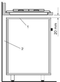
text_image
1 2 20 mmFig. A
i ILVE
INSTALLATION
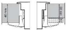
Built-in installation
Built-in installation
All the built-in tops are designed to be mounted on furniture with surfaces of any material and with a thickness varying from 3 to 4 cm. To avoid excessive overheating of the side and rear walls, it is recommended to drill the hole for the surface recessed, at a minimum distance of 45-50 mm, respecting the measurements shown in the table (pic. 1). To avoid infiltration of liquids under the worktops, it is essential to apply the appropriate healing (C) which is supplied with the top.
Fixing to the cabinet is done with the brackets that are supplied with the appliance (pic 2a, 2b, 2c).
For counter tops (HP665, HP965, HP1265, HAP95, HAP125, HP90, HP120 ...), the support surface must have the surface base equal to the appliance and a strength such as to support a weight of at least 100 kg.

Pic. 2b
(mod. HP65, HP75, HP95, HP125)
Installing and securing the cooktop
Our appliances can be fitted as:
- freestanding. Class 1
- fitted between units, Class 2/1
• built-in into units, Class 3
The minimum distances from the furniture must be:
• between top and overhead hood 650 mm
- between top and overhead cabinet 700 mm
- between top and back wall 50 mm
• between top and overhead side wall 50 mm
• between top and lower wall 20 mm
- the built-in top fitted onto a base unit with door must be installed according to picture A
- the cooking hobs for supported appliances must support a weight of at least 100 kg
• the furniture must resist at least up to 120°C
• the thickness of the top must be at least 3 cm
The built-in appliances must be inserted (see pic. 1). fixed (see pic. 2a, 2b) with the brackets, applying the appropriate seal (C) between the furniture and the appliance. The application of the hob in the furniture can also be done with an oven below paying attention to the path of the power cable that must not come into contact with hot surfaces (50 ° C beyond the environment).
i ILVE
26 27
INSTALLATION
INSTALLATION
Built-in tops' hole size
MOD. H30 - H30P - H30C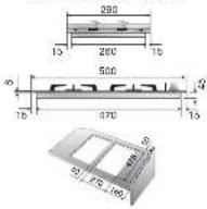 | MOD. HP75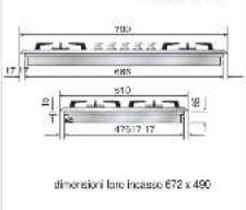 | MOD. HP45F |
| MOD. H36dimensioni foro incasso 555 x 475 - 'H60 = 50 | MOD. HP65dimensioni foro incasso 570 x 490 | MOD. H39dimensioni foro incasso 635 x 475 - 'H90 = 50 |
| MOD. H38dimensioni foro incasso 755 x 475 | MOD. HP95dimensioni foro incasso 890 x 490 | MOD. XLP90dimensioni foro incasso uts x 50 |
Built-in tops' hole size

i ILVE
28 29
INSTALLATION
INSTALLATION
Built-in tops' hole size

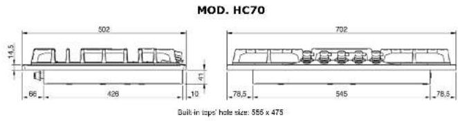
text_image
MOD. HC70 502 702 14,5 41 66 426 10 78,5 545 78,5 Built in taps' hole size: 555 x 475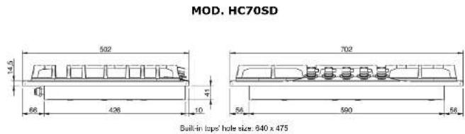
text_image
MOD. HC70SD 502 14.6 86 426 10 41 702 56 590 56 Built-in top hole size: 640 x 475
text_image
MOD. HC90 502 15 66 426 38 10 862 56 750 56 Built-in tops: hole size: 835 x 475i ILVE
INSTALLATION
Electric connection

The appliances are prepared for connection to the voltage shown on the data plate.
Before connecting the appliance to the mains check that:
- the electromagnetic switch or the socket are able to support the appliance's load (see data plate);
- the power supply system must have an efficient earth.
The appliance is supplied with a cable but without a plug: the connection must be made taking into account that the green-yellow cable is the earth conductor 12 and it must never be interrupted.
For direct connection to the mains, it is necessary that:
- the relief valve and domestic system can support the equipment's load (see data plate)
• the power supply system must have an efficient earth
- the socket or omnipolar switch, with a minimum 3 mm contact opening, must be easily reached once the appliance has been installed a mains shut-off must be incorporated in accordance with installation rules.

The green-yellow earth cable must never be interrupted even by the switch. The power cable must be routed in such a way that it does not come into contact with surfaces that have a temperature greater than 50°C above room temperature. If cable replacement is necessary contact the after-sales service.
| Power (230V) (240V) | |
| Hotplate (∅ 115) 550 W 600 W | |
| Hotplate (∅ 115) 920W 1000 W | |
| Hotplate (∅ 115) 1380 W 1500 W | |
| Barbeque 1900 W 2070 W | |
| Barbeque* 2650 W 2880 W |
* HP965B, HP1265B, HP90B, HP120B
INSTALLATION
INSTALLATION
Gas connection and transformation
Gas connection
(UNI CIG 7129/7131)
The appliances must be attached to the gas pipeline with rigid or flexible metal pipes (maximum length 2 metres) suitable for gas appliances. The connection pipes and their maximum length must comply with the applicable standards, replaced before the expiry date (if indicated on the pipe) and connected to the appliance by a coupling:
A) Directly on the ISO R228 fitting (seal with ISO R228 seal), if the pipe path allows it, see pic. 3
B.1) In the event that the connection should be directed (right-left-low), it is necessary to interpose the fitting (pic. 4a - fig. 4b) supplied
B.2) For the seal between the pipe and the ramp use the gasket (ISO R228) pic. 4a
B.3) For sealing on the thread (ISO R7) conical fittings with the thread seal must be used (pic. 4b)
B.4) To improve the seal a mastic suitable for GAS can be used.
When the gas is drawn from a cylinder, the appliance, supplied with a pressure regulator compliant with standard UNI-CIG 7432, must be connected: with flexible stainless steel pipes along the wall, according to standard UNI-CIG 9891, with 2 metres maximum extension and sealing gasket according to standard UNI 9264..
Precautions for using the product with gpl gas
The gas taps fitted in your kitchen must work with liquid gas of controlled quality, supplied at the proper nominal pressure. This pressure must be guaranteed by a special certified pressure regulator. The use of gas coming from uncertified sources and/or the improper use of the GPL cylinder as well as the relative regulator, can invalidate the product's guarantee. It is especially necessary to avoid all the situations that could pollute the gas with residues and impurities that, when introduced into the gas circuit, can irreparably damage the control components such as taps and thermostats. It is recommended to:
- use only GPL cylinders coming from official retailers and authorised by the various manufacturers;
- use the cylinders until empty without inclining or overturning them;
- carry out regular cleaning of the filter at the pressure regulator inlet;
WARNING
When the connection is made, it is recommended to check the connections' seal with special foams (NO FLAMES).
IMPORTANT
Periodically check the gas connection pipe's good condition and replace it when there are signs of anomalies.
i ILVE
30
31
i ILVE
INSTALLATION
Gas connection and transformation


Any adjustment, maintenance, etc... must be made by an authorised technician after having disconnected the appliance from the mains and shut off the gas supply.
i ILVE
INSTALLATION
INSTALLATION
Adjustment and/or adapting to different types of gas

The hobs are delivered to operate as indicated on the data plate. If a transformation should be necessary, proceed as described in the next paragraph.
Adjustment and/or adapting to different types of gas
Injector replacement and air adjustment for models:
H30 - H360 - H380 - H39 - HF40 - HP45F - HP65 - HP75 - HP95 - HAP95 - XLP90F - HP1230 HP125 - HAP125 - HP665 - HP965 - HP1265 - HP90 - HP120
- Remove the grill and the burners from the worktop.
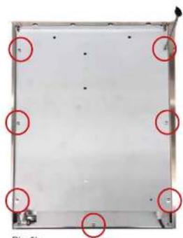
- Unscrew the screws marked with the arrows that fix the worktop to allow it to be raised, pic. 5, pic. 5a, pic. 5b.
- Unscrew venture pipe screw "F" (pic. 6, pic. 7) and open completely the air regulator "R".
- Unscrew the injectors (U) and replace them with those suitable for the gas in use and supplied with the appliance. Refer to table 1 on page 19.
- Air adjustment is made by the special regulator "R" based on the "X" values shown in table 1, on page 19, opening of primary air. When adjustment is over block the regulator "R" with screw "F".
Pic. 5
natural_image
Close-up of a kitchen appliance with a black lid and a red circle highlighting a small object on the surface (no text or symbols visible)Pic. 5a

natural_image
Close-up of a mechanical component with three red-circled holes and small pins, no visible text or symbols.i ILVE
INSTALLATION
Gas regulation
natural_image
Exterior view of a rectangular metal frame with red circles highlighting corners and a small vehicle at the bottom (no text or symbols)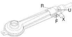
text_image
R U F XPic. 6

Pic. 7
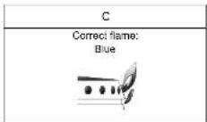
Examples of air regulation (for information)
| A | B |
| Flame with too much air:small and drawn.Decrease the "X" amount | Flame with scant air:Irregular with yellow points.Increase the "X" amount. |
i ILVE
34
INSTALLATION
INSTALLATION
Gas jets adjustment table
Gas jets adjustment table
| SR | R | P | C | DUAL | DUAL | ||
| Cona (W) | 4.80 | 2.62 | 3.40 | 4.30 × 1.0^10 | 4.50 × 3.67^10 | 5.00 × 3.67^10 | |
| Cona (W) | 127 | 198 | 225 | 210 | 227 | 264 | |
| Cona (W) | 0.60 × 0.85^10 × 0.85^2 | 0.50 × 0.75^10 × 0.90^2 | 1.20 × 1.57^10 × 1.85^3 | 1.70 × 2.25^10 × 1.90^2 | 0.92 | 0.37 | |
| Cona (W) | 20.125^10 × 10^9 | 44.00 × 10^-10 | 87.00 × 10^-10 | 104.00^10 × 10^9 | 27 | 77 | |
| (YST8) | 0.005218 × 20.00 × 10^9 | 0.63 | 0.78 | 0.82 | 1.05 | 0.26 | 0.59 |
| 0.005319 × 10^9 | 0.58 | 0.58 | 0.75 | 0.95 | 0.33 | 0.33 | |
| 0.005718 × 10^9 | 0.62 | 0.74 | 0.82 | 0.92 | 0.38 | 0.35 | |
| 0.0057607 | 0.67 | 1.17 | 1.35 | 1.50 | 0.66 | 1.40 | |
| 0.0057608 | 0.67 | 1.10 | 1.19 | 1.35 | 0.66 | 1.35 | |
| 0.0057609 | 1.00 | 1.30 | 1.45 | 1.65 | 2.60 | 2.50 | |
| 0.0057610 | 1.04 | 1.33 | 1.50 | 1.80 | 3.00 | 3.00 | |
| 0.0057611 | 1.35 | 1.73 | 2.00 | 2.20 | 3.60 | 4.50 | |
| 0.0057612 | 1.35 | 1.66 | 2.00 | 2.20 | 3.70 | 4.50 | |
| 0.0057613 | 1.06 | 1.25 | 2.25 | 2.60 | 3.82 | 4.50 | |
| 0.005818 × 10^9 | 1.90 | 2.45/2.70* | 3.20/2.85* | 3.30 | 1.02 | 2.30 | |
| 0.0125667 × 10^9 | 1.75 | 2.12/2.25* | 3.20/2.48* | 3.20 | 1.02 | 2.30 | |
| 0.0125678 × 10^9 | 1.66 | 1.40 | 3.30/2.85* | 3.30/3.68* | 1.10 | 2.92 | |
| (CDC37) | 0.00531 | 0.38 × 0.52^10 | 0.38 × 0.42^10 | 0.42 × 0.52^10 | 0.50 × 0.64^10 | 0.67 | 0.61 |
| 0.005318 × 10^9 | 0.55 | 0.55 | 0.60 | 0.60 | 0.60 | 0.60 | |
| 0.005319 × 10^9 | 0.55 | 0.55 | 0.60 | 0.60 | 0.60 | 0.60 | |
| 0.0100520 × 10^9 | 0.55 | 0.55 | 0.60 | 0.60 | 0.60 | 0.60 | |
| (S67D) | 0.00531 | 2.00 | 2.30 | 2.00 | 2.00 | 20.20 | 20.00 |
| 0.01 | 2.40 | 1.90 | 3.25 | 6.85 | 26.50 | 47.00 | |
| 0.01 | 2.40 | 1.90 | 3.25 | 6.85 | 26.50 | 47.00 | |
| 0.02518 × 10^9 × 10^9 | 2.00 | 2.30 | 3.25 | 6.85 | 26.50 | 47.00 | |
| 0.02518 × 10^9 × 10^9 | 2.00 | 2.30 | 3.25 | 6.85 | 26.50 | 47.00 | |
| 0.0100520 × 10^9 | 2.00 | 2.30 | 3.25 | 3.00 | 1.00 | 2.30 | |
| 0.01517 × 10^9 × 10^9 | 2.00 | 2.30 | 3.25 | 3.00 | 1.00 | 16.00 | |
35
i ILVE
INSTALLATION
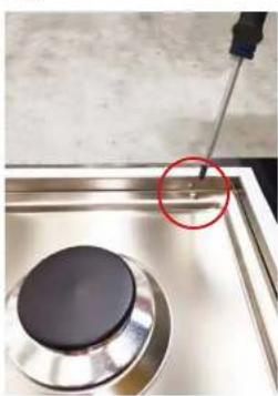
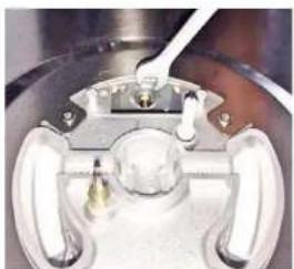
Replacement of the injectors
HC60-HC70-HC90
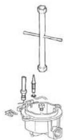
- Remove the grill and the burners from the hob.
- SR - R - P burners: unscrew injectors "U" using a 7-mm spanner (fig. 8) and replace them with those for the new gas according to table number 2 on page 20.
- DCC – Dual burners: unscrew the 2 screws "P" and remove cover "C" fig. 9. unscrew injectors "U" using a 7-mm spanner (fig. 10, fig.11) and replace them with those for the new gas according to table number 2 below.
Pic. 8

text_image
P C PPic. 9
natural_image
Close-up of a mechanical component with metallic parts and a central hub (no visible text or symbols)Pic 10

natural_image
Close-up of a mechanical component with a metallic tool inserted, showing no visible text or symbols.Pic. 11
i ILVE
36
INSTALLATION
INSTALLATION
Cooking hob table HC60, HC70, HC90
Cooking hob table
| SR RP DCC | DUAL | ||||||
| Cuau KX | 1,00 L797 | 3,67 L257 | 3,19 L487 | 4,20* 14,30* 3,40* 2,5 L7 | 4,52* 3,92* 2,7 L7 | ||
| Greeg h° 19-210 25 | - | - | 1,20 L370* 1,35* | 806* 1818 | 327 | ||
| Cuii UZ | 540 L55* 10-45* | 0,65 0,78* 12,88* | 1,20 L370* 1,35* | 1,20 L370* 1,35* | 0,30 | ||
| Cucipic | 29 L76* 49* | 44 L59* 48* | 37 L40* 98* | 104 L60* 195* | 22 | ||
| G0003-25,2025 max (KB) - 0,22 L570* 222,26 102 11,05 022,24 022 1,37 022 | |||||||
| G0003-10heter | 0,28 L64* 17,76 | 2005 06 10022 08141 | 1815 041 0422 0670 0815 | - | - | ||
| CB1.8 max | 0,27 L65* 156,78 | 2005 06 10022 08141 | 2215 041 0422 0670 0815 | - | - | ||
| CB1.25-lb AUSTRALIA | 0,20 022 | 0,00 022 | 0,00 022 | 1,12 022 | 0,80 002 | 1,12 022 | |
| G02 25 min | 0,37 021 | 1,30 723 | 1,30 723 | 1,50 1040 | 0,73 02 | 1,42 123 | |
| G02 12 min, 0,5164 L1 | 1,01 L92* 130 | 2022 25 0022 156 022 067 0022 12 10127 | - | - | |||
| G02 25 min, 0,5164 L11 | 1,50 010 152 010 141 062 062 062 110 | 1,41 010 141 062 062 110 | - | - | |||
| G05 2 min | 1,20 020 134 | 2022 14 022 042 | 0,36 0,72 0,98 150 1,932 | - | |||
| G05 2 min | 0,28 020 136 | 2022 14 022 042 | 0,36 0,72 0,98 140 1,932 | - | |||
| G05 35 lbr | 0,34 020 136 | 2022 14 020 032 | 0,36 0,72 0,98 140 1,932 | - | |||
| G05 35 min | 1,20 020 134 | 2022 14 020 032 | 0,36 0,72 0,98 140 1,932 | - | |||
| G05 12 min | 0,38 020 136 | 2022 14 020 032 | 0,36 0,72 0,98 140 1,932 | - | |||
| G05 1 min | 1,01 022 | 2,75 0125 | 2,75 0125 | 3,67 0038 | 1,45 0038 | 1,50 0038 | |
| G100 min | 1,00 L64*2 | 275 0125 | 275 0125 | 3,67 0038 | 1,45 0038 | 1,50 0038 | |
| G0003 | 2,36 | 0,85 | 0,85 | 0,85 | 1,21 | 1,26 | |
| G00 | 85 04 | 94 04 | 94 04 | 94 04 | 94 04 | 94 04 | |
| G05 | 85 04 | 94 04 | 94 04 | 94 04 | 94 04 | 94 04 | |
| G05 12 min | - | - | - | - | - | - | |
| G05 12 min | - | - | - | - | - | - | |
| G100*120 | - | - | - | - | - | - | |
| TCPL | W-5110V201 | - | - | - | - | - | |
37
i ILVE
INSTALLATION
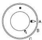
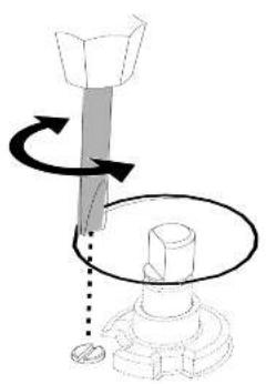
Adjustment of minimum

When installing the appliance, we recommend checking that the hob's burner minimum has been properly adjusted: a proper adjustment is that when passing from the maximum position to the minimum position, the flame is reduced, stable and homogeneous. If the flame on minimum is incorrect or if the gas has been changed, adjustment must be carried out as follows:
- Light one burner at a time and turn the flame up to maximum.
- Remove the knob of the corresponding gas tap..
- Turn the tap to minimum position.
- Using a small flathead screwdriver, unscrew, turning to the left, to increase the flame, or screw to the right to decrease it: the by-pass to be adjusted is indicated by the figure B1 and B2.
- If a liquid gas is used (Butane-Propane), the screw (by-pass) must be fully screwed in.
natural_image
Diagram showing a mechanical assembly with a rotating shaft and base, no text or symbols presentPic. B1

text_image
by-passi ILVE
38 39
WIRING DIAGRAMS
Keys
INSTALLATION
Keys
| 00 Black | |
| 11 Brown | |
| 22 Red | |
| 33 White | |
| 44 Yellow | |
| 45 Yellow-Green | |
| 55 Grey | |
| 66 Blue | |
| AA Electrical ignition transformer | |
| C Switch | |
| F Phase | |
| K1 | Earth wire for terminal board |
| K2 | " lower resistance |
| K3 | " for oven fan |
| K4 | " circular resistance |
| K5 | " upper resistance |
| K6 | " oven lamp 1 |
| K7 | " oven lamp 2 |
| K8 | " rotisserie |
| K9 | " cooling fan |
| K10 | " selector |
| K11 | " oven thermostat |
| K12 | " programmer/timer |
| K13 | " grill |
| K14 | " el. hotplate |
| K15 | " flame |
| K16 | " barbacue |
| K17 | " fryer |
| L1 | Oven lamp |
| L2 | Oven lamp |
| M | Terminal board |
| MA | Electrical ignition microswitch |
| MD | Grill microswitch |
| MG | Rotisserie |
| MP | Door microswitch |
| N | Neutral |
| P | Timer/Programmer |
| P | Timer/Clock |
| PE | Electric hotplate |
| R1 | Upper heating element |
| R2 | Lower heating element |
| R3 | Grill heating element |
| R4 | Circular heating element |
| R5 | Berbecue heating element |
| R6 | Fryer heating element |
| RE | Energy regulator |
| S1 | Oven warming light |
| S2 | Mains power warming light |
| S3 | Grill warning light |
| S4 | Cooling fan warming |
| S5 | Barbecue warming light |
| S6 | EL holplate warming light |
| S7 | Turnsplit warming light |
| S8 | Residual heat warning light |
| S9 | Fryer warming light |
| SP | Sparking plug |
| T | Grill thermostat |
| TF | Oven thermostat |
| TR | Fryer thermostat |
| TS | Safety thermostat |
| TT | Cooling fan thermostat |
| V | Oven fan |
| VT | Cooling fan |
i ILVE
WIRING DIAGRAMS
§ = only models with electric barbecue

text_image
MA MA MA MAMA AA 11 66 RE 30 S5 P1 2 0C R5 11 P2 4 0C SP M N F K1K15K16 4EModels H392..., H391...
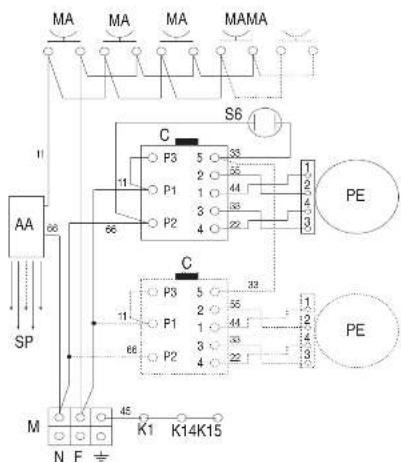
text_image
MA MA MA MAMA S6 C P3 5 33 2 55 1 44 3 33 P1 4 22 P2 4 22 11 66 AA SP C P3 5 33 2 55 1 44 3 33 P1 4 22 P2 4 22 11 68 M N F K1 K14K15 PE PEi ILVE
40 41
INSTALLATION
TROUBLESHOOTING
Troubleshooting Guide
- During the warranty period repairs can only be carried out by the authorized After-Sales Service.
- Before repairing, disconnect the appliance from the mains, ie, disconnect the power cord or unscrew the fuse.
- Unauthorized interventions and repairs may cause electrocution or short circuit, so do not perform them. Leave this work to authorized technicians.
- In the case of minor disturbances you can try to solve the problem by following the instructions.
• The assistance service during the warranty is not free, if the device does not work for incorrect use. - The elimination of faults or complaints, which were caused by use or incorrect installation, will not be repaired under warranty. Warranty costs will be charged to the user.
Below you will find some advice on rectifying some common problems.
| PROBLEM | POSSIBLE CAUSE | ELIMINATION |
| The flame is not uniform. | Gas regulation not suitable. | The gas regulation must be controlled by an expert |
| The flame changes suddenly. | The burner parts are not posi- tioned correctly. | Position the burner parts correctly. |
| To light the burners, keep the ignition knob pressed for longer. | The burner parts are not posi- tioned correctly. | Position the burner parts correctly. |
| After ignition the fame goes out. | The knob was not pressed long enough or was pressed too gently. | Keep the knob pressed longer, before releasing it, press strongly. |
| The grill in the burner area has changed color. | A natural phenomenon due to the high temperature. | Clean the grill with metal clean- ning detergent. |
| Electrical operation is generally disturbed. | Igniter or terminal block da- maged. | Check the ignition and / or the terminal block and replace it if it is damaged. |
| The electric ignition no longer works. | Food or detergent residues between the ignition electrode and the burner. | Clean carefully between the ignition electrode and the burner. |
| The burner lids are dirty. | Normal dirt. | Clean the lids with metal clean- ning detergent. |
If the problem persists despite observing the instructions above, call the authorised after-sales service.
i ILVE
INSTALLATION
NOTESNOTES
iWarranty
REGISTER YOUR WARRANTY ONLINE NOW
GO TO: ilve.com.au > support > product registration
As a part of our continued customer service offering, you can
now register your ILVE products online at
ilve.com.au > support > product registration
Just follow our simple online registration process.
Please ensure that you always keep your proof of purchase in order for your warranty to remain valid should you ever need to use it.
As always, you can contact us on
1300 856 411
INSTALLATION
WARRANTY
Eurolinx Pty Limited A.B.N. 50 001 473 347 trading as ILVE ("ILVE")
Office:
48-50 Moore Street, Leichhardt N.S.W 2040 Post:
Locked Bag 3000, Annandale, N.S.W 2038 P: 1300 856 411
WARRANTY REGISTRATION
Your ongoing satisfaction with your ILVE product is important to us. We ask that you complete the enclosed Warranty Registration Card and return it to us so that we have a record of the ILVE product purchased by you, Alternitivley, you can now register your warranty online at http://support.eurolinx.com.au/
PRIVACY
ILVE respects your privacy and is committed to handling your personal information in accordance with the National Privacy Principles and the Privacy Act 1988 (Cth). A copy of the ILVE Privacy Policy is available at www.ilve.com.au. ILVE will not disclose any personal information set out in the Warranty Registration Card ("Personal Information") without your consent unless required by:
-
law:
-
any ILVE related company;
-
any service provider which provides services to ILVE or assist ILVE in providing services (including repair and warranty services) to customers. Our purpose in collecting the Personal Information is to keep a record of the ILVE product purchased by you, in order to provide a better warranty service to you in the unlikely event that there is a problem with your ILVE product. ILVE may contact you at any one or more of the addresses, email addresses or telephone numbers set out in the Warranty Registration Card. Please contact ILVE on 1300 694 583 should you not wish to be contacted by ILVE.
WARRANTY
- Warranty
ILVE warrants that each ILVE product will remain, for a period of twenty four (24) months computed from the date of purchase of the ILVE product, free from defects arising in the manufacture of the ILVE product ("Warranty"). Except for consumer guarantees set
out in the Competition and Consumer Act 2010 (Cth) ("Act"), ILVE does not make any further warranties or representations in relation to ILVE products.
- What is not Covered by the Warranty.
The Warranty does not apply if an ILVE product is defective by a factor other than a defect
arising in the manufacture of the ILVE product, including but not limited to:
(a) damage through misuse (including failure to maintain, service or use with proper care), neglect, accident or ordinary wear and tear (including deterioration of parts and accessories and glass breakage):
(b) use for purpose for which the ILVE product was not sold or designed;
(c) use or installation which is not in accordance with any specified instructions for use or installation;
(d) use or operation after a defect has occurred or been discovered;
(e) damage through freight, transportation or handling in transit (other than when ILVE is responsible);
(f) damage through exposure to chemicals, dusts, residues, excessive voltage, heat, atmospheric conditions or other forces or environmental factors outside the control or ILVE;
(g) repair, modification or tampering by the purchaser or any person other than ILVE, an employee of ILVE or an authorised ILVE service contractor ^* ;
(h) use of parts, components or accessories which have not been supplied or specifically approved by ILVE.
(i) damage to surface coatings caused by cleaning or maintenance using products not recommended in the ILVE product handbook provided to the purchaser upon purchase of the ILVE product;
(j) damage to the base of an electric oven due to items having been placed on the base of the oven cavity or covering the base, such as aluminium foil (this impedes the transfer of heat from the element to the oven cavity and can result in irreparable damage); or
(k) damages, dents or other cosmetic
imperfections not affecting the performance of the ILVE in respect of an ILVE product purchased as a "factory second" or from display
The Warranty does not extend to light globes used in ILVE products.
- Domestic Use
Each ILVE product is made for domestic use. This Warranty may not extend to ILVE products used for commercial purposes.
- Time for Claim under the Warranty
You must make any claim under this Warranty within twenty eight (28) days after the occurrence of an event which gives rise to a claim pursuant to the Warranty, by booking a service call on the telephone number below.
Continued over...
WARRANTY
- Proof of Purchase
Customers must retain proof of purchase in order to be eligible to make a warranty claim in respect of an ILVE product.
- Claiming under the Warranty
Customers will bear the cost of claiming under this Warranty unless ILVE determines the expenses are reasonable, in which case the customer must claim those expenses by providing written evidence of each expense to ILVE at the address on the Warranty Registration Card.
- Statutory Rights
(a) These terms and conditions do not affect your statutory rights.
(b) The limitations on the Warranty set out in this document do not exclude or limit the application of the consumer guarantees set out in the Act or any other equivalent or corresponding legislation in the relevant jurisdiction where to do so would: (i) contravene the law of the relevant jurisdiction; or
(ii) cause any part of the Warranty to be void. (c) ILVE excludes indirect or consequential loss of any kind (including, without limitation, loss of use of the ILVE product) and (other than expressly provided for in these terms and conditions) subject to all terms.
conditions and warranties implied by custom, the general law, the Act or other statute.
(d) The liability of ILVE to you for a breach of any express or non-excludable implied term, condition or warranty is limited at the option of ILVE to:
(i) replacing or repairing the defective part of the ILVE product;
(ii) paying the cost of replacing or repairing the defective part of the ILVE product;
(iii) replacing the ILVE product; or
(iv) paying the cost of replacing the ILVE product. (e) Our goods come with guarantees that cannot be excluded under the Australian Consumer Law. You are entitled to a replacement or refund for a major failure and for compensation for any other reasonably foreseeable loss or damage. You are also entitled to have the goods repaired or replaced if the goods fail to be of acceptable quality and the failure does not amount to a major failure.
- Defects
Any part of an ILVE product deemed to be defective and replaced by ILVE is the property of ILVE. ILVE reserves the right to inspect and test ILVE products in order to determine the extent of any defect and the validity of a claim under the Warranty.
*For your closest ILVE authorised service agent go to
https://support.eurolinx.com.au/#/map/retailers
All warranty service calls must be booked through ILVE's Customer Care Centre on customercare@eurolinx.com.au or
1300 85 64 11 option 1
01072021
Warranty Card tear off
| WARRANTY REGISTRATION CARD Please complete and send to ILVE at: REPLY PAID 83617 01072021 LEICHARDT NSW 2040 | ||
| Last Name: First Name: | ||
| Address: | ||
| State: Postcode: Email: | ||
| Home Phone: Mobile: | ||
| Purchase Date: / / (Please attach proof of purchase to validate warranty) | ||
| MODEL NUMBER | SERIAL NUMBER (if you cannot locate the serial number please call ILVE on 1300 85 64 11) | |
| 1 | ||
| 2 | ||
| 3 | ||
| 4 | ||
01072021
eurolinx LUXURY KITCHEN APPLIANCES

text_image
L-12 Cleveland St Clerkwood, IL 30 48 50 Mozen St Lockwood, USANATIONAL SERVICE CENTRE
Our high quality appliances are designed and manufactured to give you many years of cooking pleasure.
Should you have any questions or issues with your appliance please email our national service centre
customercare@eurolinx.com.au or phone us on 1300 85 64 11.
Our experienced staff are on hand to log your service request and ensure any matter is attended to promptly.
For after sales enquiries please contact us at customercare@eurolirx.com.au or 1.300 85 64 11 option 1 For spare parts contact us at spares@eurolirx.com.au or 1.300 85 64 11 option 2
Technical support is available to authorised and licensed service providers only by contacting us at
tech.support@eurolinx.com.au All other technical enquiries should be directed to customercare@eurolinx.com.au
P: 1300 694 583 E: info@euroline.com.au W: euroline.com.au

LIVE WITH
ILVE
FOLLOW US ON:

facebook.com/ILVEappliances

instagram.com/ILVE_appliances
YouTube
youtube.com/ILVEappliances
BLOG
livewithlve.com
Australia National Telephone Number 1300 MYILVE (694 583) New Zealand Telephone Number 64 3 344 5913
ILVE showroom hours: Tuesday to Friday - 8am-5pm, Saturday - 10am-4pm, Sunday and Monday - closed
* Melbourne showroom hours: Tuesday to Saturday - 10am-4pm
ilve.com.au