CHG642WA - Stove Chef - Free user manual and instructions
Find the device manual for free CHG642WA Chef in PDF.

User questions about CHG642WA Chef
0 question about this device. Answer the ones you know or ask your own.
Ask a new question about this device
Download the instructions for your Stove in PDF format for free! Find your manual CHG642WA - Chef and take your electronic device back in hand. On this page are published all the documents necessary for the use of your device. CHG642WA by Chef.
USER MANUAL CHG642WA Chef
User and Installation Manual
MODELS
GHS607S/W, GHC607S/W, GHC617S/W, GHS917S/W, GHC937S/W, 72K315S/W, GHR12S/W, GHR92S, WHG640SA/WA, CHG642SA/WA, CHG646SA/WA, CHG956SA/WA, CHG606SA, SHG646SA, SHG956SA, WHG641SA, WHG643SA, WHG645SA/WA, WHG951SA, WHG955SA/WA
CONGRATULATIONS
Congratulations and thank you for choosing our Gas Cooktop. We are sure you will find your new appliance a pleasure to use and a great case in your cooking. Before you use the appliance, we recommend that you read through the whole user manual which provides a description of the product and its functions.
To avoid the risks that are always present when you use a cooking appliance, it is important that the appliance is started correctly and that you read the safety instructions carefully to avoid misuse and hazards. For future references, please store this booker in a safe pace. This appliance complies to the requirements of Australian Standard AS4551.
CONDITIONS OF USE
This appliance is intended to be used in household and similar applications such as:
- Stall kitchen orees in work, offices and other working environments
- Farm houses
- By clients in hotels, hotels and other residential type environments
- Bed and breakfast type environments
Record model and serial number here:
Model
Serial number
the symbols you will see in this booklet have these meanings:

warning
Indirects information concerning your personal safety

caution
Indicates information on how to avoid damaging the appliance

tips & information
Indicoreps and information about use of the experience

environmental tips
Indicators' ps and information about economical and ecological use of the appliance

tips & information
Important - check for any damage or marks
If you find the appliance is damaged or marked, you must report it within 7 days if you wish to claim for damage marks under the manufacturer's warranty. This does not offer your statutory rights.

environmental tips
Information on disposal for users
- Most of the packing materials are recyclable. Please dispose of those materials by contacting your local authorities and ask for the correct method of disposal.
2 CONTENS Gas Coilers Gas Coils (GENERAL MATTER)
CONTENTS
General safety 3
Using your cooktop 4
Cleaning and care 5
Troubleshooting....6
Technical data 7
Installation....11 LPG conversion - Dong Yang Regulator....13 LPG conversion - Chant Regulator....15 Electrical connection....16 Testing appliance operation....17
Warranty 19
general safety
Read the following carefully to avoid an electric shock or fire
General warnings
- This appliance is not intended for use by persons (including children) with reduced physical sensory or mental disturbances, or lack of experience and knowledge, unless they have been given supervision or instruction concerning use of the appliance by a person responsible for their safety.
- Young children should be supervised to ensure they do not pay with this appliance.
- During use this appliance becomes hot. Care should be taken to avoid touching hot exence and internal surfaces when in use. Use oven gloves. Children should be kept away to avoid bare and scattle.
- This appliance must NOT be used as a space heater
- Keep verb clear of obstructions,
• In order a invalid a fire, the appliance must be kept clean. - Do not spray aerosols in the vicinity of the appliance when it is in operation
- Do not store formicole materials in a order the appliance, eg. aerosols.
- Do not modify its appliances.
Cooktops (generally)
- Do not allow oats to be dry, as damage to both pan and cooktop may result.
- Do not operate the cooktop for or extended period of time without a pot or pan on the horolare.
- Do not allow large cookware to overhang the cooker onto the ad-acorn benchtop. This will cause scorching to the benchtop surface.
- Do not allow cooking pots or pans to intrude into the area which is close to the controls.
- Ensure barrier cops and levels are properly located. [see Figure 1]
- For maximum stability, ensure parts and parts are centrally located on the levels.
- Handles should be tuned away from the front of the bench to avoid accidents
- Only models fitted with flame safeguard can be used in marine craft, catavons or mobile homes.
Figure 1

text_image
burner cap burner crown ignition electrode injectorNOTE: You must read these warnings carefully before installing or using the desktop. If you need assistance, contact your Customer Care Department. The manufacturer will not accept liability should the instructions below, or any other safety instructions incorporated in this book, be ignored.
Installation
- An authorised person must install this appliance and MUST provide a certificate of compliance.
- Before using the appliance, ensure that all packing materials are removed from the appliance
- "order to avoid any potential hazard, the installation instructions in this booklet and any label on the appliance, must be followed.
- Ensure that all specified venue openings and air spaces are not blocked.
- Where the appliance is built into a benchtop, the benchtop material must be capable of withstanding temperatures of 8.5°C.
- DO NOT install in marine craft, conversions or mobile homes because those products are not fitted with a flame safeguard on each burner
Servicing
• Servicing MUST only be carried out by authorised personnel.
- to maintain sale operation, it is recommended that the product be inspected every five years by or authorised service person.
- for trip owners applied with a supply card, if the supply card is damaged it must be replaced by an authorized service person in order to avoid a hazard.
- For models with battery ignition, the battery will require periodic replacement (see page 2).
NOTE: The battery is a perishable item and is not covered by the warranty.
Cleaning
- Always ensure the appliance is turned off before cleaning.
- This appliance contains aluminium fittings. DO NOT use caustic based cleaners.
- Do not use steam cleaners as this may cause moisture build up on electrical components.
• Always mean the appliance immediately after any load spillage. - DO NOT place bumer cops, crowns or gridole plate in a dishwasher.
using your cooktop cleaning and care

warning
DO NOT spray acrosses in the vicinity of this appliance while it is in operation on a netoxole can contain lumonazole propellants.

warning
Where the coaction is installed in any condition area, the area must be properly ventilated. It MUST NOT be used on a space heater.
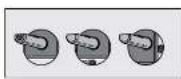
Controls
Each bumper is controlled by a control knob. The restings on the control panel indicate which bumper the knob controls and the settings for that bumper [see Figure 21.
Figure 2

Lighting burners
Electronic ignition: These cooktops are fitted with mains powered or battery ignition. When the oppliance has been connected one the power is on, depressing any knob will release sparks to all currents (except main button ignition, see push button ignition mode). To light a burner, destine the car-exporting knob and run to the HIO^2 position (while depressing the knob). The knob may be released once the force is established.
Flame safeguard models
The knob must be turned to the "high" position, then pushed down as far as possible for approximately 5 seconds. If the flame goes out when the knob is reversed, simply cleaves the knob again, his time holding 1 down with slightly more lines for the same length of time. The height of the flame can be varied by turning the control knob toward the "low" position.
Push button ignition: from the knob to the "HCH" position and press the ignition button down until the flame is established. The height of the flame can be varied by turning the knob towards the "LOW" position.

warning
Keep brands clear of the lanes when lighting. If the burner does not light within 5 seconds, too loud; or 'Off' position, okay gets to disperse them by lighting again.

caution
Burners MUS: be operated between "HIGH" and "OW" settings only in the absence of electrical power, carry out the ignition directly to the barrel with a band held ignition source.
Hotplates
Choice of hotplate
For your convenience here is a choice of helpful
- A small burner for special low seat and slow cooling - A medium burner for normal cooking and simmering
• A large burner for fast heating and large pots and pans.
- A wok owner for very fast heating using a wok or large pot or pan.
To conserve gas pieces the pan centricly over the bumer and adjust the flame to trust it does not extent past the edge of the pan (Figure 3). Do not cool food too rapidly. A vigorous boil will not cook food any faster, and will waste energy.
Pots and pans
All common pots and pans: aluminum, stainless steel, cast iron, ceramic, etc., may be used on your new gas cooktop. Ensure that the nuts or pans are steady and have flat bases to avoid dangerous spillover of hot liquids and wasted energy.
Figure 3
Choice of flame height

acquired - one (or by) oral
sell an en-gro vate and possible
hands, a means.

Gone: kne height
Gas speed
Choice of cooking utensils

for a large butter
over a large cream

For a small one, we are small ones
! caution
Never use asbestos mats, wire mats or grids, or aluminium foil, as it can lead to overheating, cracked chromel or broken glass. The warranty will be sold if these items are used and cost a failure. Works should only be used on the work carrier and work support trivet.

warning
Ensure the appliance is off and too before clearing
Enamel
Pension stains may require rubbing with a nylon counter or cleaned powder cleanser. Household summer cleanser are ovatohne, follow the manufacturer's instructions in their use. Hair closer cleaners, powder cleansers, stool wool or wax polishes should not be used.
Stainless steel
NOTE: Ensure any oil is cleared on the holo before use, otherwise it may cause the holo to turn a yellowish colour. All grades of stainless steel may stain, direction or stain on adhering layer of grims in normal opacron. To achieve movement surface epocorance, stainless steel must be kept clean by regularly using the following staining procedures. Wash with warm soapy water and rinse with clean water. Where the stainless steel has become extremely dirty with signs of surface discolouration, [due to periods of neglect or misuse] use a stainless steel detector. When removing heres animals, be sure to follow the polar or bushing lines.

caution
DO NOT use abrasive securers or steel wool.
Trivets, burner caps and crowns
There can all be lifted off and removed for ascaride cleaning. NOTE: When refitting the burner cape and crowns, ensure that they are correctly seated.
Ensure bumors are thoroughly chided after cleaning or spoilage. When cleaning the bumer, ensure that all the bumer parts are tree of any baggage (refer to figure 1b on page 4). If necessary, use a toothpick or brush to clear parts. The outer surface of the bumer capto mark a portions finish and some cross necessary to be taken to avoid touching the surface during cleaning. In instances of heavy sailing, it may be necessary to apply to non-abtrusive cleaning compound one rub with a cloth until the sailing is removed and then finish with a sole dry cloth.

caution
DO NOT place trees or barriers in the rich areas
Ignition electrode
CENTLY clean the ignition soak plug and flame safeguard sensor with a damp cloth to avoid lighting difficulties. Ensure that they are dry before use
Injector
Ensure the injector remains free of any foreign material. It necessary, use a thin piece of wire to clear the office.
troubleshooting
If you have a problem with me cooktop, check the toole below. You may be able to solve the problem and this will save you from paying for a service call. You will have to pay for a service call even in me warranty period if the problem is one listee below.
Table 1
| problem possible cause solution | ||
| burner will not light ever though the scotter is working | Gas supply valve turned off turn or gas supply to opalience | |
| Control knob no on turn slots on (refer to page 3) | ||
| Wrong knob turned | Ensure the knob you are turning corresponds to the burner you want to light | |
| Knob no, held down long enough in 'High' position for flame solegicoid (where filled) to engage | Repeats lighting procedures and fold knob down for 5 seconds in 'High' position refer page 41 | |
| Port blockage in ignition once | Ensure that ports in ignition area are clean and dry | |
| Ignition electrode wet or dry Dry or clean ignition electrode | ||
| Stocking is wrong point because of Incorrectly tied burner crown | Ensure that the crown is seated properly to that the spark lies to the receiving point in the burner crown refer to Figure 11 | |
| Injector is blocked Ensure injector is clear of foreign material | ||
| No spark is obtained when can of knob is activated | Electrically empty is connected or switched of | Switch on electricity or check uses |
| Battery is Tat Replace battery refer to page 1/25 | ||
| Poverty wrong on battery | Reorient battery to correct position refer to page 1/21 | |
| Ignition electrode wet or dry Dry or clean light fire electrode | ||
| Flame unknown or tarding is ill | Flame ports blocked or wet Clean or dry flame ports | |
| Burnen caps/crown incorrectly filled Ensure these components and filled comes: y | ||
| Flame no daging on when knob is released | Knob nor set between "IGH" and LOW' Knob MUST be set between those positions | |
| Knob no, held down long enough in 'High' position for flame solegicoid (where filled) to engage | Repeat lighting procedure and hold knob down for 5 seconds in 'High' position refer page 41 | |
| low heat, low cooking income: cooking pot or pan being used Refer to Figure 3 (page 4) | ||
| Benchtop or knobs sworhearing | Incorrect cooking pot or pan used Refer to Figure 3 (page 4) | |
| Pot or pan not located on burnt proximity. | Ensure pot or pan is centrally located on burner | |
| Cooktop stainless steel discolored | Pot or pan being used is too large | Ensure pot sizes used are as per user manual requitors. Clean with STEEL POWER loose (face through space pole) |
If all the above points have been checked and there is still a problem with the cooktop please call the Service Centre.
technical data
| ILLIORS | G 1500'S/W | G 1500'S/W | G 1501'S/W | G 1501'S/W | G 1503'S/W |
| Brand | Chef | Chef | Chef | Chef | Chef |
| Cooking move | 4 | 4 | 4 | 4 | 4 |
| Walk | No | No | Yes | Yes | Yes |
| Ignor | 1.5V battery | 220.240V | 220.240V | 1.5V battery | 220.240V |
| Trips | Wire Cross | Wire Cross | Wire Cross | Wire Cross | Wire Cross |
| Lob motorol | Stainless Sea/Interrupted White | Stainless Sea/Interrupted White | Stainless Sea/Interrupted White | Stainless Sea/Interrupted White | Stainless Sea/Interrupted White |
| Features | Flesh button ignition | Ignor through knob | Ignor through knob | Flesh button ignition | Ignor through knob |
| Thermo-archival | No | No | No | No | No |
| Go+ Types | NG, [P conversion] in supplied | NG, [P conversion] in supplied | NG, [P conversion] in supplied | NG, [P conversion] in supplied | NG, [P conversion] in supplied |
| Cooking dimension | |||||
| Width (mm) | 600 | 600 | 600 | 600 | 850 |
| Depth (mm) | 300 | 335 | 335 | 310 | 310 |
| Height (mm) | 55 | 58 | 58 | 58 | 58 |
| Colour dimension | |||||
| Width (mm) | 570 | 570 | 570 | 530 | 830 |
| Depth (mm) | 400 | 400 | 400 | 400 | 400 |
| Energy setting (kJ) | |||||
| Small power | 3.1 MWh | 3.1 MWh | 3.1 MWh | 3.1 MWh | 3.1 MWh |
| Medium power | 2×9.0 MWh | 2×9.0 MWh | 2×9.0 MWh | 9.0 MWh | 2×9.0 MWh |
| Large power | 12.1 MWh | 12.1 MWh | 12.1 MWh | 12.1 MWh | |
| Work power | 14.4 MWh | 14.4 MWh | 14.4 MWh | ||
| Total MWh | 35.2 MWh | 35.2 MWh | 37.5 MWh | 40.6 MWh | 49.6 MWh |
technical data
| LADURS CI KBE105A/WA CI GS405A/ | WA CI I39565A/WA | CI IG405A /2K3 | BS/W | |
| Brand Chef Chef Chef | Coch | |||
| Cooking menu 4 PS | 4 | |||
| Walk Yes Yes Yes | Yes | |||
| Ignition 1-5V battery | 220 240V 220 240V | 220 240V | ||
| Trice Win Class | Wite Mot | Wite Mot | Wite Mot | |
| Job matr a | Stainless Steel/Innacelle White | Stainless Steel/Innacelle White | Stainless Steel/Innacelle White | Stainless Steel |
| Features | Ignition through knob | Ignition through knob | Ignition through knob | Ignition through knob |
| Firm tabgunirl | No | No | No | No |
| Gas Types | NG, LP conversionk supplied | NG, LP conversionk supplied | NG, LP conversionk supplied | NG, LP conversionk supplied |
| Cronlon dispersion | ||||
| With (min) 600 | 600 | 600 | 600 | |
| Depth (min) 330 | 330 | 310 | 330 | |
| Height (mm): 58.58.58 | 58 | |||
| Circat dispersion | ||||
| With (min) 570 | 570 | 530 | 570 | |
| Depth (min) 700 | 700 | 470 | 470 | |
| Energy using (NGL) | ||||
| Small burner | 2 × 1 M/h | 2 × 1 M/h | 2 × 1 M/h | 2 × 1 M/h |
| Medium burner | 2 × 9.0 M/h | 2 × 9.0 M/h | 2 × 9.0 M/h | 9.0 M/h 2 × 9.0 M/h |
| Large burner | 12.1 M/h | 2.1 M/h | ||
| Walk burner | 14.4 M/h | 14.4 M/h | 14.4 M/h | 14.4 M/h |
| Tota (MJ/s) | 37.5 M/h | 37.5 M/h | 49.6 M/h | 49.6 M/h |
technical data
| FLAVORS | SH3646SA | SH3936SA | GI 1125/W | GI 992S | WI GC40SA/WA |
| Brand | Simson | Simson | Westinghouse | Westinghouse | Westinghouse |
| Cooking power (L/kW) | |||||
| Walk | Yes | Yes | No | Yes | No |
| Ignor | 220.2kW | 220.2kW | 220.2kW | 220.2kW | 220.2kW |
| Trist | Wire Mall | Wire Mall | Wire Mall | Wire Mall | Wire Mall |
| Job material Stainless Stea | Stainless Stea | Stainless Steel/Frenetled White | Stainless Steel | Stainless Steel/Frenetled White | |
| Features | Ignor through knob | Ignor through knob | Ignor through knob | Ignor through knob | Ignor through knob |
| Home safeguard | No | No | No | No | No |
| Gas Types | NG, 12 conversionlit supplied | NG, 15 conversionlit supplied | NG, 15 conversionlit supplied | NG, 15 conversionlit supplied | NG, 15 conversionlit supplied |
| Light (mm) | 50 | 50 | |||
| Color dimension | |||||
| Width (mm) | 570 | 830 | 570 | 830 | 570 |
| Depth (mm) | 470 | 470 | 470 | 470 | 470 |
| Energy rating (kWh) | |||||
| Small turner | >1 MWh | >1 MWh | >1 MWh | >1 MWh | >1 MWh |
| Medium turner | 2×9.0 MWh | 2×9.0 MWh | 2×9.0 MWh | 2×9.0 MWh | 2×9.0 MWh |
| Large turner | 12.1 MWh | 2.1 MWh | 2.1 MWh | 12.1 MWh | |
| Walk turner | 14.4 MWh | 14.4 MWh | 14.4 MWh | ||
| Total MWh | 37.5 MWh | 49.6 MWh | 35.2 MWh | 49.6 MWh | 35.2 MWh |
technical data
| LALUKS W/ K6V 15A W/ K6M35A W/ K6M35A/WA W/ GFB 15A W/IGP9505A/WA | |||||
| Band Westinghouse Westinghouse Westinghouse Westinghouse Westinghouse | |||||
| Cooking mays / 4.4 kg | |||||
| Walk Yes Yes Yes Yes | |||||
| Ignition | 220.2kV | 220.24kV | 220.24kV | 220.24kV | 220.24kV |
| Tires | Wire Net | Wire Net | Cone Iron | Wire Net | Cone Iron |
| Job materials | Stainless Steel | Stainless Steel | Stainless Steel/Unsupplied White | Stainless Steel | Stainless Steel/Unsupplied White |
| Features | Ignition through knob | Ignition through knob | Ignition through knob | Ignition through knob | Ignition through knob |
| Pane safeguard | No | Yes | Yes | No | Yes |
| Gas Types | NO2 (IF conversion & supplied) | NO2 (IF conversion & supplied) | NO2 (IF conversion & supplied) | NO2 (IP conversion & supplied) | NO2 (IP conversion & supplied) |
| Cooking dimension | |||||
| With (mm) | 600 | 600 | 600 | 860 | 860 |
| Depth (mm) | 530 | 530 | 530 | 510 | 510 |
| Height (mm) | 58.58 | 58.58.58 | |||
| Closet dimension | |||||
| With (mm) | 570 | 570 | 570 | 830 | 830 |
| Depth (mm) | 490 | 490 | 490 | 470 | 470 |
| Energy using (NC) | |||||
| Small burner | 5.1 M/s | 5.1 M/h | 5.1 M/s | 5.1 M/s | 5.1 M/s |
| Medium burner | 9.0 M/s | 9.0 M/s | 9.0 M/s | 2 x 9.0 M/s | 2 x 9.0 M/s |
| Large burner | 12.1 M/s | 12.1 M/s | 12.1 M/s | 12.1 M/s | 12.1 M/s |
| Wax burner | 14.4 M/s | 14.4 M/s | 14.4 M/s | 14.4 M/s | 14.4 M/s |
| Irral W/s | 40.5 M/s | 40.5 M/s | 40.5 M/s | 47.6 M/s | 47.6 M/s |
installation
Table 2
| Cooktop dimensions | Square | Rectangular |
| width (mm) | 600 | 860 |
| depth (mm) | 535-510 | |
| height (mm) | 58 | 58 |
| Cut-out dimensions | ||
| width (mm) | 570 | 830 |
| depth (mm) | 490-470 |

caution
Coatings are supplied for use with natural gas [NO]. To use with IPG, the infectors MUST be changed using the conversion kit supplied. Refer UP Conversion on page 13 and 15).
This appliance must be installed by an authorised person and in compliance with.
- AS/NZS 5601.1 Gas Installations Part 1: General Installations, and AS/NZS 5601.2 Gas Installations Part 2: IP Gas Installations in car owners and boats for non-properative purposes, or the relevant installation code for gas appliances in your country.
2 The local gas fting regulators, municipal building codes, electrical wiring regulations and any other relevant statutory regulations. -
The particular instructions as given below. Before commencing installation, check to ensure that the appliance gas type given on the data plate on the appliance corresponds with the type of gas to which it is intended the appliance be connected.
√ A certain issue of compliance MUST be given to the customer after the application is successfully isolated. -
This appliance must be earned (240V models only).
Installation procedure
- The bench cutout should be made as per cutout dimensions in Tabic 2 and Figure 4.
2 Aceton walls, outboards and protection for combustible materials: Ensure that the appliance is installed in accordance with clouses 6.2.5 one 6.10.1.1 of AS/NZS 5601.1, or clouses 6.9.1 and 6.9.5 of AS/NZS 5601.2 with regard to clearness to combustible surfaces and materials, and cleavances to rubberods and extruded lamps
To ensure clearances of 200nm from tumors to ventral combustible surfaces observe the minimum distance requirements shown in Figure 5
Clearances to combustible surfaces may be reduced if combustible surfaces are protected in accordance with clause 6.10.1.2 of AS/NZS 5601.1, or clause 6.9.2 of AS/NZS 5601.2
NOTE: For installation into a standard 600mm width benchtop the clearance specified can not be achieved and combustible surfaces must be protected in accordance with the above clauses.
- Optional barrier: A barrier can be installed to prevent accelerated contact with the cooktop base, where the base of the cooktop is accessible from below it. Inside a cupboard, etc. An impression has been incorporated into the nose to ensure a minimum clearance of 10cm is maintained between the base and the barrier. This barrier may be made at any rigid material.
Barrier protection is not necessary if the product is installed above an underbench oven or similar appliance and/or if the cupboard construction is such that the underside of the cooking is no accessible.
Figure 4
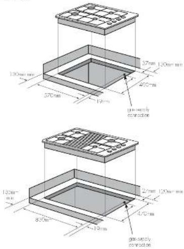
text_image
130mm mm 570mm 27mm 130mm mm 400mm pre-supply connection 130mm 825mm 19mm 2/2mm 120mm mm 4/20mm gas supply connectioninstallation installation LPG conversion -
DONG YANG regulator
Figure 5

text_image
110mm 1 115mm wall4 Fitting the cooktop into the bench. Carry out as follows:
- Place the rubber seal provided around the edge of the hob. NOTE: The rubber seal has trade powder applied to its surface which should be wiped off with a comp cloth offer the unit has been installed.
Figure 6

text_image
mutter box hob base box bumpstop clamp screw- Fit the out-down cloros supplied to ensure that the cooktop cannot move after installation.

warning
Failure to fix the cooktop to the bench coat result in loosening of the gas connection through movement of the cooktop and a gas leak may result
- Use the 4 clamps and 4 screws supplied in the parts bag.
- To assemble, attach the 4 clamps to each corner of the corner box via the screw provider.
- When placing the cooktop in the cutout, swing the clamps parallel with the box to avoid interference with the cutout
- Position: the cooktop so it is centred, then owing the clamps under the benchtoo and tighten.
Operation on NG/SNG
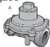
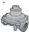
Regulator
An appliance regulator is provided. The regulator must be positioned so that the pressure test nipple is accessible when the appliance is installed. Connect the gas supply to the 12 " B.S.P. internal thread inlet of the regulator. Refer to 'bronch colour' (Figure 4) for connection point position.
Regulators are supplied pre-adjusted and configured by the component maker for use with Natural Gas. The appliance installer is not required to move an adjustment to obtain the correct outlet pressure setting.
An arrow on the base of the regulator indicates the direction of gas flow when the inlet and outlet of the regulator is oriented correctly. When the regulator has been filled check for leaks from the connections with a noisy water.
Gas connection
This appliance is supplied for use with Natural Gas.
However, it can be converted for use with LPG. Refer to LP conversion on pages 13-15.
Supply pipe sizing
The total hourly gas consumption for the appliance is shown on the table. The required supply pressure (i.e., at inlet to appliance regulator) for each gas type is shown on the table, and given in table 3. Use this information in conjunction with the length or run, number of elbows, roses and bands, the available service pressure and the supply requirements of other installed appliances to determine a millitude pipe slice for accordance in this matter refer to the appropriate section of AS/NZS 5601. or AS/NZS 5601.2.
An AGA certified class B or D. Deelie connection may be used to locate: the cookup in accordance with AS/N/S 5001.1, in particular section 5.9 and case 6.10.18, or AS/N2S 5001.2, in particular section 2.11. Where a house assembly is used and the cookup is in the finest portion, the house assembly should be suitable for connection to a fixed consumer piping outlet located at a point 800 - 650mm above the floor and in the region outside the width of the distance to a distance of 750mm. The point of connection to consumer piping must be accessible with appliance installed.
Elbow positioning
It is possible to reposition the elbow if required by basening the locking nut and elbow by using two sponsors. Reftigation the entire assembly after the elbow has been repositioned. When fitting elbow to appliance, ensure that the sealing washer is fitted.
Checking the gas supply
- Check the monometer zero point is correct.
2 Connect the parameter to the cooktop measure point. This is located on the regulator. - Turn on the gas supply and electricity and try to ignite the gas.
i
tips & information
It will take additional time to light the gas for the first time as air needs to be poured from the pipe.
- With the appliance operating check the outlet pressure
- when all burners of the appliance are operating at maximum.
-
when the smallest buffer of the appliance is operating at minimum.
Under these conditions the outlet pressure should not vary from the nominal outlet pressure of 1.00kPa by more than +/-0.20kPa.
If the regulator appears to not be performing satisfactorily, then check the following points. -
If the outlet pressure is consistently too low then the inlet pressure may be too low and adjustment of an upstream regulator may be needed, or an upstream regulator or valve with insufficient flow capacity may be present in the gas supply line. If this is suspected then it may be necessary to respect the checks while
measuring both the inlet and outlet pressure to determine if the inlet pressure is in the range 1.13–5kPa.
- Check that the regulator has been fitted to the gas supply line in the correct orientation, the arrow on the base of the body indicates the direction of gas flow.
Once these checks have been coerulees, if the regulator still fails to perform in a satisfactory manner it should be replaced

tips & information
Refer to page 15 if you have been supplied with a CHANT regulator
This appliance is fitted with Natural Gas burner injectors.
Please follow the procedure below if a conversion to suit IP gas is required. The conversion kit contains appropriate IPG indicators and 1 LPG sticker.
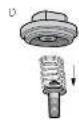
To convert to LPG
- Remove the hotplote corners to access the hotplote injectors. Replace the hotply fitted NG injectors with the appropriate injectors, as supplied from Tools 31.
- Unclean the next no from the regular, the hex nut, boss washer and nylon inlet will disengage as on assembly.
- Use the rylon insert from the nut assembly by cooling the insert ½ turn, and pulling it free.
- Turn over the insert, and clip back into position.
- Rent the box not assembly to the regulator ensuring that it is fully screwed down. The regulator is now set for connection to IP.
- Turn on the gas supply and at each new connection check for looks using soapy water; each norlate valve should be turned on, one at 3:10 PM, and the injector hole blanked off for several seconds.
-
The operation of the regulator can be confirmed by connecting a numerator to the pressure test point located on the side of the regulator body adjacent to the outlet. With the appliance operating check the outlet pressure
-
when all burners of the appliance are operating at maximum,
-
when the smallled barrel of the appliance is operating at minimum.
Under these conditions the outlet pressure should not vary from the nominal outlet pressure of 2.60 kPa by more than +/-0.52 kPa -
If the regulator appears to not be performing satisfactorily then check the following points.
-
If the outlet pressure is consistently too low, then the inlet pressure may be too low and adjustment of an upstream regulator may be needed, or on upstream regulator or valve with insufficient flow capacity may be present in the gas supply line, it this is suspected then it may be necessary to repeat the checks what measuring both the inlet and outlet pressure to determine if the inlet pressure is in the range 2/5\~400Kts.
- Check that the insert has been fired correctly as per diagram figure 7. Check that the box nut is fully screwed down.
LPG conversion - DONG YANG regulator
- Check that the regulator has been fired to the gas supply line in the correct orientation, the arrow on the base of the body indicates the direction of gas flow. Once there checks have been completed, if the regulator still fails to perform in a satisfactory manner it should be replaced.
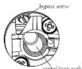
- One by one, turn the knob to minimum and screw in the bypass screw (accessible when the knob is removed after figure 11) until a small stable flume results. Turn the knob to maximum and then back to minimum to ensure that the correct minimum flume is maintained.
- Attach the LPG sticker to the cooker, near the gas supply slot. Cover the Natural Gas labo that is Kentucky liened.
Table 3
| BURNER TYPE | NATURAL GAS | ROS | ||
| Nominal fuel point pressure: 1.00 gal | Nominal fuel point pressure: 2.50 gal | |||
| Inpatient area (km2) | consumption (MJ/h) | Inpatient area (km2) | consumption (MJ/h) | |
| Small burner | 1.05 | 5.1 | 0.50 | 4.0 |
| Medium burner | 1.35 | 9.0 | 0.70 | 6.5 |
| Large burner | 1.60-12.1 | 0.90-10.7 | ||
| Weak burner | 1.75-14.2 | 1.00-13.0 | ||
Figure 7

LPG conversion - CHANT regulator

tips & information
Refer to page 13-14 if you have been supplied with a DONG YANG regulator.
This appliance is supplied set up for Natural Gas usage. A conversion kit is included with the product for Universal LPG usage. The conversion kit contains the appropriate injection and 1 LPG sticker.
Please follow the procedure below + a conversion to suit UNIVERSAL IPO is required:
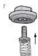
- Remove the hospitals rivers, bumer caps and bumer crowns to access the hotline injectors. Replace the factory filled injectors with the approximate injectors, as supplied. Refer to injector or ice table for injector sizes. The injector size is stamped or the side of the injector.
- Unscrew the top hat nut from the regulator. The top hat nut and control pressure spring assembly will disengage as an assembly.
- Uncrew the threaded pin from lap ho
- Upturn threaded pin, so spring is free and screw pin back into the top hat until 1 pm.
- Roll the top hot net assembly to the regulator ensuring that it is fully screwed down. The regulator is now set for connection to IPC.
- Turn on the gas supply one or each new connection check for leaks using soapy water. Each hopplate valve should be turned on, one at a time, and the injector hole blanked off for several seconds.
-
The operation of the regulator can be confirmed by connecting a monometer to the pressure, eat point located on the size of the regulator body adjacent to the outlet. With the appliance operating check the outlet pressure
-
when all burners of the appliance are operating at maximum.
- when the enteral corner of the appliance is operating at minimum.
Under these conditions the outlet pressure should not vary from the nominal outlet pressure of 2.00kPa by more than +0.52kPa.
8. If the regulator appears to not be performing satisfactorily than check the following points:
- If the outlet pressure is consistently too low, then the inner pressure may be too low and adjustment of an upstream regulator may be needed, or an upstream regulator or valve with insufficient flow capacity may be present in the gas supply line.
- If this is suspected then it may be necessary to repeat the checks whilst measuring both the inlet and outer pressure to determine if the inlet pressure is in the range 2.75 - / COkPa
- Check that the man has been filled correctly
- Check that the tuned screw is fully screwed down
- Check that the regulator has been filled to the gas supply line in the correct orientation, the arrow on the base of the body into cases the direction of gas flow.
Once these checks have been correlated, if the regulator still fails to perform in a satisfactory manner it should be replaced.
- One by one, turn the knots to minimum and screw in the bypass screw (accessible when the knot is removed) until a small stable flame results. Turn the knob to maximum and their back to minimum to ensure that he covers minimum flame is maintained.
- Attach the LPG sticker to the cooker, near the gas supply inlet. Cover the Natural Gas label that is factory filled.
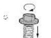
Figure 8
tap hat of one-by
fully screwed door

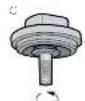
configuration for natural gas

or equation for LPG


electrical connection testing appliance
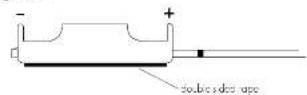
Battery connection
The battery used is a 1.5 Vα-¹⁸A⁻ Battery. This supplies the power for the ignition system of the stockup. To install, follow the safety instructions as shown on Figure 9 below.
NOTE: Pay special attention to the orientation of the battery when invelling.
The battery supplied is a perishable item and not covered by the warranty.
Electrical connection (220-240 Volts)
Where applicable, the appliance is supplied with a standard 7.5 Arm service cord terminated by a 3-pin plug for connection to a standard household socket. The electrical supply is required to power the electronic ignition system. NOTE: It will be necessary for servicing purposes to disconnect the electrical power supply. The power point should therefore be accessible after the appliance is installed, as specified in the local existing regulations.
Diagram 1 is a schematic of the wiring in the appliance.
The weight of the unit is printed on the appliance packaging label.
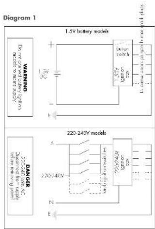
text_image
Diagram 1 1.5V battery models WARNING Do not follow battery high meets to turn supply Batter switch N/A N/A N/A 220-240V models DANGER Discovered from battery before removing part N/A N/ABattery holder installation instructions
- Locate a convenient position to mount battery holder, keeping it away from hot surfaces.

DO NOT attach it to the base of the cooktop
-
Ensure mounting surface is clean
-
Remove protective tape from rear of holder and stick in place
Figure 9
Use of hose assemblies
Ensure that the hose assembly is restored from accident contact with the 'blue door' of an underbench oven or any other hat surface of an adjacent support.
operation
After installation, test the appliance and ensure that it operates correctly before ranging it over to the customer. The following procedure is recommended:
- Iron on the gas and electricity supply and attempt, signal can on all tumors, born separately and in combination. For correct procedure, refer to page 4'. Note that additional time needs to be allowed for the initial lighting as air has to be purged from the pipes.
- Observe the flame appearance or each bumer. Figure 10: If it is much larger or much smaller than expected, the injector size and supply pressure require checking. Where a flame is unsatisfactory, refer to the Troubleshooting Guide (Page 6) to correct the fault. If the Troubleshooting Guide does not solve the problem, call the Service Centre.
- When all the foregoing is satisfactory, check the rundown (in mini-low) setting on each barm, as this may need to adjust next. Vives have a by-pass controlling screw, which may be accessed by removing the lines. This screw will be located on a particular area of the voice. Refer Figure 11. Normally, this will have been correctly set at the factory for use on NG (Nursom Good and should not require adjustment.
If the appliance has been converted to IPS, then me bypass screw will have to be traversed in until a small substitute time so
Please ensure the supply pressure has been checked PRIOR to any adjustment. - If the appliance cannot be adjusted to perform safety, inform the customer of the problem and it's an appropriate warning notice to the appliance. If the fault appears to be dangerous the appliance should be a connected. If a minor fault exists, the customer may wish to use the appliance while awaiting service.
If a fault cannot be fixed, please call the Service Centre. - The customer should be advised that, in the event of a fault, the local Service Organisation or the retailer from whom the appliance was purchased should be contacted.
- When satisfied that the unit is operating correctly, turn off and instruct the customer on correct operation as outlined in this booklet. Ask the customer to operate the controls to ensure that the correct procedure is understood

Servicing must only be carried out by an authorised service person.
Injector sizes required for various gas types are shown in Table 3 (page 14). The appliance inlet pressure for each gas type is also shown.
for model identification can offer installation, an additional data clone sticker has been provided. This sticker is to be stuck onto adjacent cabinetry.
Figure 10

Figure 11
Bypal screw
Electrolux Warranty
FOR SALES IN AUSTRALIA AND NEW ZAFI AND
APPIANG: ILII IN DM-N, COOKTCP
AND RED STANDING COOKERS
This document sets out the terms and conditions of the product warranties for Electrolux Appliances. It is an important document. Please keep it with your proof of purchase documents in a safe place for future reference should you require service for your Appliance.
- In this warranty
(3) 'acceptable quality' as related to in clause 10, his warranty has the same meaning related to the ACL.
(b) 'ACL' means Schedule 2 to the Competition and Consumer Act 2010.
(c) 'Appliances' means any Heatched product purchased by you and accompanied by this document;
(b) 'Electrolux' means Electrolux Home Products Pty Ltd of 163 O'Border Street, Mason NSW 2020. ABN 51 054 762 841 In respect of Appliances purchases in Australia and Electrolux (NZ) Limited (collectively 'Electrolux') of 3-5 Nial Burgess Road, Mount, Wilmington, in respect of Appliances purchased in New Zealand
"major failure" se referred to in clause 10 of this warranty has the same meaning referred to in the AGI and includes a situation when an Appliance cannot be repaired or it is uneconomic for Electrolux, at its discretion, to repair an Appliance during the Warranty Period
(j) 'Warranty Period' means the Appliance is warranted against manufacturing defects in Australia for 24 months and in New Zealand for 24 months, following the date of original purchase of the Appliance;
To 'you' means the purchaser of the Appliance not having purchased the Appliance for resale, and 'your' has a corresponding meaning
-
This warranty only applies to Appliances purchased and used in Australia, or New Zealand and uses in normal domestic applications and is in addition to land does not exclude, restrict, or modify in any way, only non-excludable statutory warranties in Australia or New Zealand.
-
During the Warranty Period Electrolux or its ASC will, at no extra charge if your Appliance is readily accessible for services, without special equipment and support to these terms and conditions, repair or replace any parts which it considers to be defective. Electrolux or its ASC may use remanufactured parts to reach your Appliance. You agree that, any replaced Appliances or parts become the property of Electrolux. This warranty does not apply to light gloves, switches, filters or similar per small parts.
-
Parts and Appliances not supplied by Electrolux are not covered by this warranty.
-
To the extent permitted by law, you will bear the cost of transportation travel and delivery of the Appliance to and from Electrolux or its ASC. If you reside outside of the service area, you will bear the cost of. (a) Taxa of an authorized representative;
(b) transportation and delivery of the Appliance to end from Electrolux or its AGC.
In all instances, unless the Appliance is transported by Electrolux or an Electrolux authorised representative, the Appliance is transported at the owner's cost and risk while in transit to and from Electrolux or his ASC.
-
Proof of purchase is required before you can make a claim under this warranty.
-
You may not make a claim under this warranty unless the defect claimed is due to faulty or defective parts or workmanship. In addition, it is not back in the following situations (which are not exhaustive):
(a) the Appliance is damaged by:
4 accident
(i) misuse or abuse, including failure to properly maintain or serve
(1) normal wear and tear
(b) power surge, electrical steam damage or incorrect power supply
(4) incomplete or improper installation
(8) incorrect, improper or inappropriate question
(5) reach or semi-implation
(vii) failure to complete with any additional instructions supplied with
The Appliance
(3) the Appliance is modified without authority from Electrolux in writing.
(b) the Appliances rental number of warranty seat has been removed or defects.
(a) the Appliance was serviced or repaired by anyone other than
Electroux, an authorized repair or AEC
-
This warranty, the contract to which it relates and the relationship between you and Einkraux are governed by the law applicable where the Appliance was purchased. Where the Appliance was purchased in New Zealand for commercial purposes the Consumer Guarantee Act does not apply.
-
to the extent permitted by law and subject to your non-exudable statutory rights and warranties. Electrolux excludes all warranties and liabilities (other than or contained in this document) including liability for any use or damage whether direct or indirect arising from your purchase, use or not use of the Appliance.
-
or Appliances and services provided by Institute in Australia, the Appliances come with a guarantee by Electrolux trial cannot be excluded under the ACL. You are entitled to a replacement or refund for a major failure and no compensation for any other reasonably foreseeable loss or damage. You can also entitle to have the Appliances repaired or replaced if the Appliances fail to be of acceptable quality and the failure does not amount to a major failure. The benefits to you given by this warranty are in addition to your other rights and commands under a law in relation to the Appliances or laws as to which the warranty relates.
-
At all times during the Warranty Period, Electrolux shall be its discretion, determine whether repair replacement or refund will apply if an Appliance has a valid warranty claim applicable to it.
-
or Appliances and services provided by Electrolux in New Zealand, the Appliances come with a guarantee by Electrolux pursuant to the provisions of the Consumer Guarantee Act, the Sale of Goods Act and the Fair Trading Act.
-
To enquire about claiming under this warranty, please follow these steps: (a) carefully check the operating instructions, user manual and the items of this warranty;
[2] Have the model and serial number of the Appliance available:
have the proof of purchase (e.g. an involved available
[3] telephone the numbers shown below.
- You accept that if you make a warranty claim, Electrolux and its ASC may exchange information in relation to you to enable Electrolux to meet its obligations under this warranty.
Important Notice
Before calling for service, please ensure that the steps listed in clause 13 above have been followed.
| FOR SERVICEor to find the address of your nearest,state service centre in Australia.PLEASE CALL 13 13 49For the cost of a local call (Austria only) | SERVICE AUSTRALIAELECTROUX HOME PRODUCTSelectrolux.com.au | FOR SPARE PARTSor to find the address of your nearest,state space parts centre in Australia.PLEASE CALL 13 13 50For the cost of a local call (Austria only) |
| FOR SERVICEor to find the address of your nearest,authorised service centre in New Zealand.FREE CALL 0800 10 66 10(Ferry Netherlands) | SERVICE NEW ZEALANDELECTROUX INZI Unitedelectrolux.co.nz | FOR SPARE PARTSor to find the address of your nearest,static space parts centre in New Zealand.FREE CALL 0800 10 66 20(Ferry Netherlands) |
like to know more?
For further information on all appliances, or to obtain detailed dimension and installation information, call into your Retailer, phone or email our Customer Care team or visit our website:
Australia
phone: 1300 363 640 fax: 1800 350 067 email: customercare@electrolux.com.au website chef.com.au (Chef models) westinghouse.com.au (Westinghouse models)
New Zealand
phone: 0800 234 234 fax: 0800 363 600 email: customercare@electrolux.co.nz website simpson.co.nz (Simpson models) westinghouse.co.nz (Westinghouse models)
Top service
Top Service encompasses the after sales service provided by The Electrolux Group to consumers including delivery, home service and spare parts.
Chef. We are part of the Electrolux Family.
To add a touch of professional inspiration to your home, visit electrolux.com.au
©2016 Electrolux Home Products Pty Ltd
ABN 51 004 762 341
ECN 061879 ANC 305387212 Drawing 3053872_MD
Print code: CMAN_GASCOOK_UM_Apr16