AGH92XFFD - Cooker Artusi - Free user manual and instructions
Find the device manual for free AGH92XFFD Artusi in PDF.

User questions about AGH92XFFD Artusi
0 question about this device. Answer the ones you know or ask your own.
Ask a new question about this device
Download the instructions for your Cooker in PDF format for free! Find your manual AGH92XFFD - Artusi and take your electronic device back in hand. On this page are published all the documents necessary for the use of your device. AGH92XFFD by Artusi.
USER MANUAL AGH92XFFD Artusi
text_image
APPLIANCES FOR LIVINGCongratulations, you are now the proud owner of an ARTUSI cooking appliance. Thank you for purchasing ARTUSI and welcome to the ARTUSI Family.
This instruction manual has been specially created to inform you of the full range of features your ARTUSI appliance has to offer and serves as an introduction to getting the very best out of your ARTUSI appliance.
We present detailed information on each of the features your ARTUSI appliance consists of. Once you have read this section you will be able to choose the most appropriate settings for your appliance when cooking different types of food.
We ask you to read the instructions in this booklet very carefully as this will allow you to get the best results from using your appliance. KEEP THE DOCUMENTATION OF THIS PRODUCT FOR FUTURE REFERENCE.
TO REGISTER YOUR PRODUCT WITH ARTUSI, PLEASE FILL OUT THE WARRANTY CARD AT THE END OF THIS BOOKLET AND POST IT TO: REPLY PAID 83617
LEICHHARDT NSW 2040
Dear Artusi Customer, please read this user manual carefully before using the product and, keep it permanently at your disposal.
Note: This user manual is prepared for more than one model. Some of the features specified in this Manual may not be available on your appliance.
All our appliances are only for domestic use, not for commercial use. Products marked with (*) are optional.
"THIS APPLIANCE SHALL BE INSTALLED IN ACCORDANCE WITH THE REGULA TIONS FORCE AND ONLY USED IN A WELL VENTILATED SPACE. READ THE INSTRUCTIONS BEFORE INSTALLING OR USING THIS APPLIANCE"
"Conforms with the WEEE Regulations."
Instructions for use
Installation
EN
All the operations concerned with the installation (electrical and gas connections, adaptation to type of gas, necessary adjustments, etc.) must be carried out by qualified technicians, in terms with the standards in force.
For specific instructions, kindly read the part reserved for the installation technician.
Use
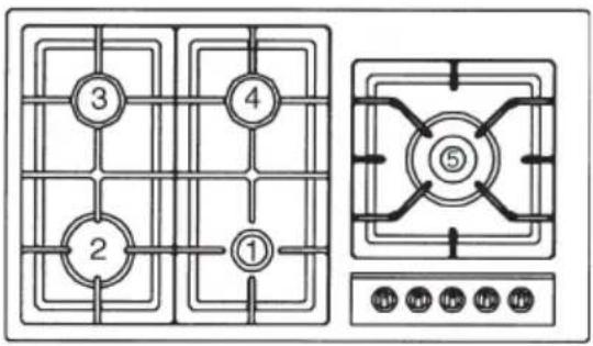
Gas burners (Fig. 1-3).
The ignition of the gas burner is carried out by putting a small flame to the upper part holes of the burner, pressing and rotating the corresponding knob in an anti-clockwise manner, until the maximum position has coincided with the marker. When the gas burner has been turned on, adjust the flame according to need. The minimum position is found at the end of the anti-clockwise rotation direction.
In models with automatic ignition, operate the knob as described above, pressing simultaneously, the corresponding push-button. For models with automatic/ simultaneous (with one hand) ignition, it is sufficient to proceed as described above using the corresponding knob. The electric spark between the ignition plug and the burner provides the ignition of the burner itself. After ignition, immediately release the push-button and adjust the flame according to need.
For models with a thermoelectric safety system, the burner is ignited as in the various cases described above, keeping the knob fully pressed on the maximum position for approximately 3/5 seconds. After releasing the knob, make sure the burner is actually lit.
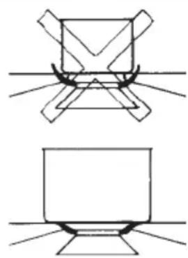
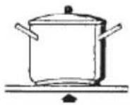
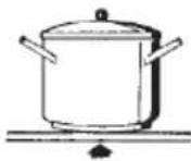
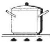
N.B. - we recommend the use of pots and pans with a diameter matching that of the burner, thus preventing the flame from escaping from the bottom part and surrounding the pot
• do not leave any empty pots or pans on the fire
- do not use any tools for grill-cooking on Crystal hobs.
When cooking is finished, it is also a good norm to close the main gas pipe tap and/or cylinder.
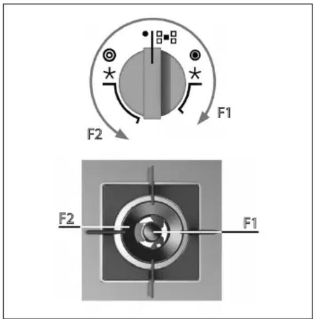
Models with Dual Wok burner
Some models have a Dual Wok burner. The centre flame (F1) can be lit by pressing the knob and turning it clockwise or the entire burner (F2) can be lit as shown the figure below.
text_image
F1 F2 F2 F1Important
- use of the appliance produces heat and moisture in the room where it is installed. Make sure the kitchen is sufficiently ventilated; keep natural ventilation holes open or install mechanical ventilation devices (such as a hood).
- Prolonged use of the appliance may require additional ventilation, such as opening a window.
- on floors with thermoelectric protection do not keep the ignite button pushed for more than 15 seconds. If the burner has not ignited after 15 seconds, open the door of the room and wait at least one minute before making a further attempt.
- on floors without protection, should the burner flame go out close the corresponding gas cock and wait at least on minute before making any attempt to ignite it.
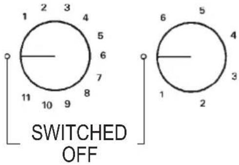
Electrical plates / Vitroceramic heating element
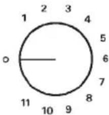
(Fig. 2-2a-3). Rotate the knob towards the position required for cooking and bear in mind that the higher the number, the higher the heat output. See table “use of electrical plates”/heatin elements vitroceramic. The pilot light signals that the plate is “on”.
Some types of pilot lights will maintain some slight luminescence even after disconnection. That is quite normal.
N.B.: When using electrical plates/heating elements vitroceramic, we
recommend flat bottom recipients with a diameter equal or slightly larger than that of the plate itself.
- avoid liquid overflow. Therefore, after boiling or heating liquids, reduce the heat output;
- do not leave the electrical plates on with empty pots and pans;
- when cooking is finished, rotate the knob back into closing and/or disconnected position.
In the event of even a slight fracture on the cooking vitroceramic surface, disconnect the electric power supply immediately.
DO NOT STARE AT THE HALOGEN LAMP.
GAS
natural_image
Two abstract line drawings of a computer monitor with base stations and screen (no text or symbols)| fish | 20x32 |
| wok | ∅ 20-32 |
| fast | ∅ 20-26 |
| semifast | ∅ 14-20 |
| auxiliary * | ∅ 10-14 |
*with reduction grid
Fig. 1
ELECTRICAL PLATES
text_image
1 2 3 4 5 6 7 8 9 10 11 SWITCHED OFF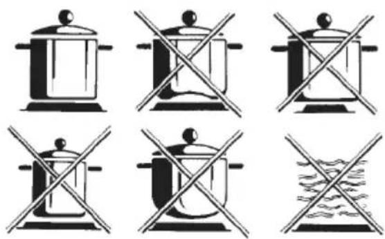
natural_image
Six identical cooking pot symbols with crossed-out lines, no text or labels presentFig. 2

text_image
1 2 3 4 5 6 7 8 9 10 11 o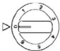

text_image
6 5 4 O 3 1 2VITROCERAMIC HEATING ELEMENTS
nonoyes
Fig. 2a
| USE OF ELECTRICAL PLATES/VITROCERAMIC HEATING ELEMENTS | |
| Commutator Energy regulator Heat intensity Cooking methods | |
| 1 1-2 slight | melting of fats etc.; heat small quantities of liquid |
| 2 3-4 mild | heating of medium quantities of liquid; puddings, long-cooking sauces |
| 3 5-6 slow | defreezing - heat large quantities of liquid; cooking below boiling temperature |
| 4 7 - 8 medium | tender roasts; cooking at boiling temperature |
| 5 9 - 10 high | roasts - boiled food; pan-frying of meats |
| 6 10 - 11 burning heat | bring large quantities of liquid to boil; fry |
EN
Maintenance Gas/Electrical
EN
Prior to any operation, disconnect the appliance from the electrical system.
For long-life to the equipment, a general cleaning operation must take place periodically, bearing in mind the following:
- the glass, steel and/or enamelled parts must be cleaned with suitable non-abrasive or corrosive products (found on the market). Avoid chlorine-base products (bleach, etc.);
- avoid leaving acid or alkaline substances on the working area (vinegar, salt, lemon juice, etc.).
- the wall baffle and the small covers (mobile parts of the burner) must be washed frequently with boiling water and detergent, taking care to remove every possible encrustation. Dry carefully and check that none of the burner holes is fully or partially clogged;
- the electrical parts are cleaned with a damp cloth and are lightly greased with lubricating oil when still warm.
- the stainless steel grids of the working area, after having been heated, take on a bluish tint which does not deteriorate the quality. To bring colour back to its original state, use a slightly abrasive product.
N.B.- Cleaning of the taps must be carried out by qualified personnel, who must be consulted in case of any functioning anomaly. Check periodically the state of conservation of the flexible gas feed pipe. In case of leakage, call immediately the qualified technicians for its replacement.
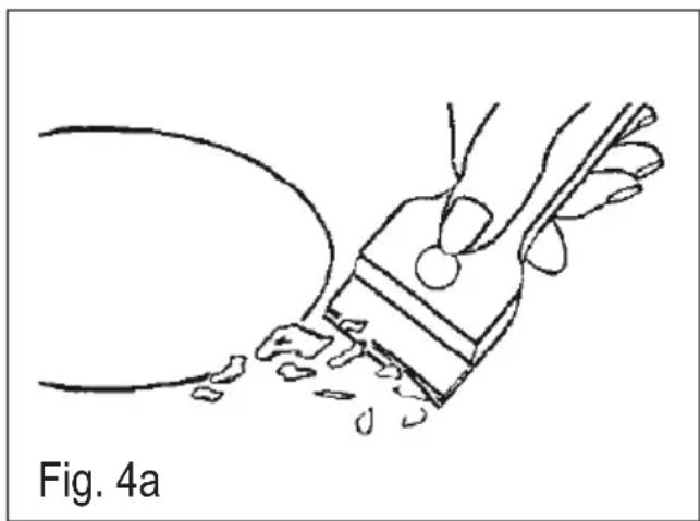
Maintenance vitroceramic surface
(Fig.-4a) First of all remove stray food bits and grease drops from the cooking surface with the special scraper (fig. 4). Then clean the hot area as best as possible with SIDOL, STAHLFIX or other similar products with a papertowel, then rinse again with water and dry with a clean cloth.
Pieces of aluminum foil and plastic material which have inadvertently melted or sugar remains or highly sacchariferous food have to be removed immediately from the hot cooking area with the special scraper (fig. 4).-This is to avoid any possible damage to the surface of the top.
Under no circumstances should abrasive sponges or irritating chemical detergents be used such as oven sprays or spot removers.
DO NOT USE STEAM CLEANERS
natural_image
Line drawing of a hand holding a tool with debris, labeled Fig. 4a (no text or symbols on the diagram itself)Instructions for the installer
Installation
This appliance is not provided with a combustion product discharge. It is recommended that it be installed in sufficiently aerated places, in terms of the laws in force. The quantity of air which is necessary for combustion must not be below 2.0 m3/h for each kW of installed power.
See table of burner power.
Note: the device is in installation class 3. The appliance's adjustment parameters are shown on the plate attached to its housing.
Positioning
(Fig. 4). The appliance can be fitted into a working area as illustrated on the corresponding figure. Before positioning the hob, fit the seal Ⓕ around the entire periphery of the hole cut in the worktop.
Gas connection
(Fig. 5) Connect the appliance to the gas cylinder or to the installation according to the prescribed standards in force, and ensure beforehand, that the appliance matches the type of gas available.
Otherwise, see “Adaptation to various types of gas”.
Furthermore, check that the feed pressure falls within the values described on the table: "User chacteristics".

text_image
ISO 7/1 ISO 228/1 (FR) Fig. 5
Rigid/semi rigid metal connection
Carry out the connection with fittings and metal pipes (even flexible pipes) so as to obtain counter stress the inner parts of the appliance.
N.B. - when the installation has been carried out, check the perfect sealing of the entire connection system, by using a soapy solution.
Electrical connection
(Fig. 6) Prior to carrying out the electrical connection, please ensure that:
- the plant characteristics are such as to fol- low what is indicated on the matrix plate placed at the bottom of the working area;
- that the plant is fitted with an efficient earth connection, following the standards and law provisions in force. The earth connection is compulsory in terms of the law.
Should there be no cable and/or plug on the equipment, use suitable absorption material for the working temperature as well, as indicated on the matrix plate. Under no circumstance must the cable reach a temperature above 50^ C of the ambient temperature.
If connecting directly to the mains power supply, fit a multi-pole switch of a
suitable size for the rated capacity with a clearance distance which completely disconnects the power line under overvoltage category III conditions, consistently with the rules of installation (the yellow/green earth wir must not be interrupted). The plug or omnipolar switch must be easily reached on the installed equipment.
To avoid all risk, if the power cable becomes damaged, it must only be replaced by the manufacturer, by an authorised service centre, or by a qualified electrician.
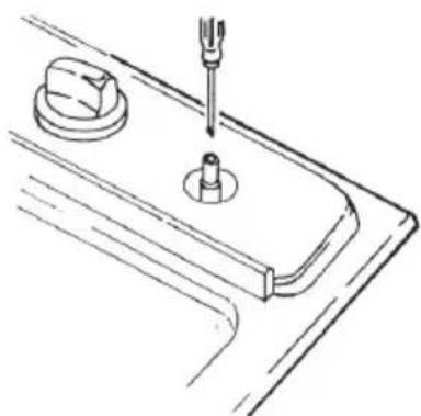
Adaptation to various types of gas
(Fig. 7) Should the appliance be re-set for a different type of gas than available, proceed as follows:
- replace the injectors (Fig. 7) with the corresponding type of gas to be used (see table "Uses characteristics")
- to adjust to the minimum, use a screwdriver on the screw placed on the tap (Fig. 8) after turning the tap to its minimum position. For LPG (butane / propane) screw tight.
1 - CABLE-CLAMP

text_image
-1 2 L N 1 2 N L2 - YELLOW / GREEN

text_image
Diagram showing two electrical circuit setups with labeled components and connections, including a battery and N-L elements.Fig. 6


natural_image
3D mechanical component diagram showing a cylindrical pin inserted into a housing (no text or symbols)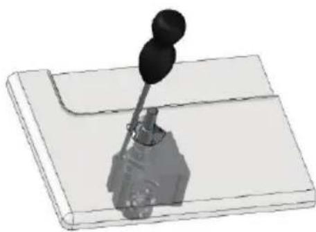
natural_image
3D rendering of a mechanical lever assembly with two circular components mounted on a base plate (no text or symbols visible)Fig. 8
natural_image
Technical line drawing of a mechanical component with a screwdriver inserted, no text or symbols present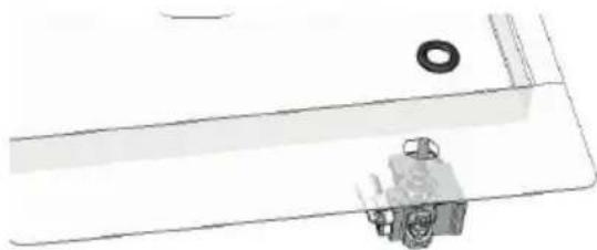
natural_image
Technical line drawing of a mechanical component with a washer and housing (no text or symbols)
natural_image
Mechanical assembly diagram showing a lever and pivot mechanism (no text or labels)
| USER CHARACTERISTICS | ||||||
| GAS BURNERS | ||||||
| FEED BURNER | ∅INJECTORS | THÉRMALAPACITYNOMINAL | CONSUMPTION | |||
| naturalgas | G20 20 | FAST 129 3000 286 | I/h | |||
| 101 1750 167SEMIFAST | ||||||
| AUXILIARY 77 1000 95 | ||||||
| WOK TDC 63A-121B 3500 333 | ||||||
| 63A-140B 4250 405WOK TDC | ||||||
| 141 3500 333WOK 3 | ||||||
| WOK 3 150 4000 381 | ||||||
| 140 3500 333WOK MW | ||||||
| 141 3500 333WOK 4 | ||||||
| FISH 118 2700 257 | ||||||
| A - ∅ 71 | 4000 381WOK DUAL | |||||
| B - ∅ 95 | ||||||
| WOK 2 | 137 3500 333 | |||||
| 145 4000 381 | ||||||
| 168 4800 457 | ||||||
| liquefiedgas | G30/G3128-30/37 | FAST 87 3000 218 | I/h | |||
| SEMIFAST 66 1750 127 | ||||||
| AUXILIARY 50 1000 73 | ||||||
| WOK TDC 37A - 90B 3500 254 | ||||||
| WOK TDC 37A - 97B 4250 309 | ||||||
| WOK 3 94 3500 354 | ||||||
| WOK 3 102 4000 291 | ||||||
| WOK MW 93 3500 254 | ||||||
| WOK 4 96 3500 254 | ||||||
| FISH 85 2700 196 | ||||||
| WOK DUAL | A - ∅46 | 4000 291 | ||||
| A - ∅65 | ||||||
| WOK 2 | 320/340 3500 255 | |||||
| 192/210 4000 291 | ||||||
| 150/160 4800 349 | ||||||
| FEED BURNER | ER | ∅INJECTORS | THÉRMALAPACITYNOMINAL | CONSUMPTION | ||
| G110/G140 8 | FAST 320/340 | 3000 680/711 | 1 | I/h | ||
| SEMIFAST 192 | /210 1750 39 | 7/415 | ||||
| AUXLIARY 150 | /160 1000 22 | 7/237 | ||||
| WOK TDC | 150A-129B | 3500/3300 794 | 783 | |||
| 175A/-360 B | ||||||
| WOK 3 350 350 | 0 794/783 | |||||
| WOK 3 350 400 | 0 907/949 | |||||
| WOK MW 310 | 350 3500 79 | 4/830 | ||||
| WOK 4 360/360 | 3500 794/8 | 30 | ||||
| FISH 255/265 | 2700 612/640 | |||||
| WOK 2 | 340 3500 79 | 4 | ||||
| 350 4000 90 | 7 | |||||
| --- 4800 --- | ||||||
| Electric Ignition 220-240V ~ 50/60Hz 0,6 W | ||||||
| ELECTRIC PLATE | |||
| FEED TYPE W ADJUSTMENT | |||
| 220-240V ~ 50/60Hz | NORMAL ∅145 | 1000 | commutator (0÷6)energy regulator (0÷11) |
| FAST ∅145 | 1500 | commutator (0÷6)energy regulator (0÷11) | |

| VITROCERAMIC | |||
| HEATING ELEMENTS | |||
| FEED TYPE W ADJUSTMENT | |||
| 220-240V ~ 50/60Hz | TRIPLE CIRCUITRADIANT∅145 - ∅180 | 1200-1700 commutator (0÷6) | |
| SINGLE-CIRCUITRADIANT∅145 - ∅180 | 1200-1700 | energy regulator(0÷11) | |
| MIXED-CIRCUITRADIANT/HALOGEN∅145 - ∅180 | 1200-1800 | energy regulator(0÷11) | |
text_image
① ② ③ ④ ⑤1 2 3 4 5

text_image
909 510 480 840
E

text_image
Technical diagram showing a mechanical assembly with labeled components and an inset detail view of a component.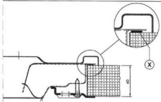
text_image
Technical diagram showing a mechanical assembly with cross-sectional view and labeled dimension '4'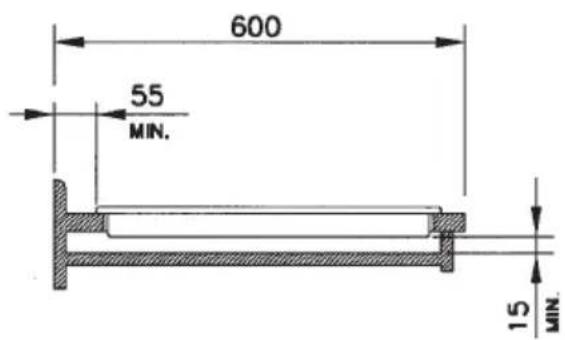
text_image
600 55 MIN. 15 MIN.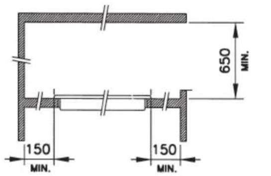
text_image
650 MIN. 150 MIN. 150 MIN.Fig. 3 - Abb. 3 - Afb. 3

ARTUSI THE ART OF LIVING
Worldwide Appliances Pty Limited
A.B.N. 45868077422
Office:
48-50 Moore Street, Leichhardt N.S.W 2040 Post:
Locked Bag 3000, Annandale, N.S.W 2038
P: 1300 694 583
WARRANTY REGISTRATION
Your ongoing satisfaction with your artusi product is important to us. We ask that you complete the enclosed Warranty Registration Card and return it to us so that we have a record of the artusi product purchased by you.
PRIVACY
Worldwide Appliances respects your privacy and is committed to handling your personal information in accordance with the National Privacy Principles and the Privacy Act 1988 (Cth). A copy of the Worldwide Appliances Privacy Policy is available at www.artusi.com.au. Worldwide Appliances will not disclose any personal information set out in the Warranty Registration Card (“Personal Information”) without your consent unless required by:
- law;
- any Worldwide Appliances related company;
- any service provider which provide services to artusi or assist artusi in providing services (including repair and warranty services) to customers. Our purpose in collecting the Personal Information is
to keep a record of the artusi product purchased by you, in order to provide a better warranty service to you in the unlikely event that there is a problem with your artusi product. Worldwide Appliances may contact you at any one or more of the address, email address or telephone numbers set out in the Warranty Registration Card. Please contact artusi on 1300 694 583 should you not wish to be contacted by Worldwide Appliances.
WARRANTY
1. Warranty
Worldwide Appliances warrants that each artusi product will remain, for a period of either 12 months or 24 months of warranty. All Warranties are valid from the original date of purchase, And warranty claims must be accompanied by the proof of purchase.
24 months warranty products: All Built-in Appliances – Limited to Ovens, Gas, Induction and Electric Cooktops, and All Rangehoods
Freestanding Cookers - Gas and Electric Models (900mm Width)
Dishwashers - Freestanding, Fully Integrated, Semi Integrated and built-in
12 months warranty products: Freestanding Cookers - Gas and Electric Models in 50cm, 54cm and 60cm Widths Portable Appliances* – Benchtop Models and Portable Gas Models
2. What is not Covered by the Warranty.
The Warranty does not apply if an artusi product is defective by a factor other than a defect arising in the manufacture of the artusi product, including but not limited to:
(a) damage through misuse (including failure to maintain, service or use with proper care), neglect, accident or ordinary wear and tear (including deterioration of parts and accessories and glass breakage);
(b) use for purpose for which the artusi product was not sold or designed;
(c) use or installation which is not in accordance with any specified instructions for use or installation;
(d) use or operation after a defect has occurred or been discovered;
(e) damage through freight, transportation or handling in transit (other than when Worldwide Appliances is responsible);
(f) damage through exposure to chemicals, dusts, residues, excessive voltage, heat, atmospheric conditions or other forces or environmental factors outside the control or Worldwide Appliances;
(g) repair, modification or tampering by the purchaser or any person other than Worldwide Appliances, an employee of Worldwide Appliances or an authorised artusi service contractor ^* ;
(h) use of parts, components or accessories which have not been supplied or specifically approved by artusi.
(i) damage to surface coatings caused by cleaning or maintenance using products not recommended in the artusi product handbook provided to the purchaser upon purchase of the artusi product;
(j) damage to the base of an electric oven due to items having been placed on the base of the oven cavity or covering the base, such as aluminium foil (this impedes the transfer of heat from the element to the oven cavity and can result in irreparable damage); or
(k) damages, dents or other cosmetic imperfections not affecting the performance of the artusi in respect of an artusi product purchased as a “factory second” or from display
The Warranty does not extend to light globes used in artusi products.
3. Domestic Use
Each artusi product is made for domestic use. This Warranty may not extend to artusi products used for commercial purposes.
4. Time for Claim under the Warranty
You must make any claim under this Warranty within twenty eight (28) days after the occurrence of an event which gives rise to a claim pursuant to the Warranty, by booking a service call on the telephone number below.
5. Proof of Purchase
Customers must retain proof of purchase in order to be eligible to make a warranty claim in respect of an artusi product.
6. Claiming under the Warranty
Customers will bear the cost of claiming under this Warranty unless Worldwide Appliances determines the expenses are reasonable, in which case the customer must claim those expenses by providing written evidence of each expense to Worldwide Appliances at the address on the Warranty Registration Card.
7. Statutory Rights
(a) These terms and conditions do not affect your statutory rights.
(b) The limitations on the Warranty set out in this document do not exclude or limit the application of the consumer guarantees set out in the Act or any other equivalent or corresponding legislation in the relevant jurisdiction where to do so would:
(i) contravene the law of the relevant jurisdiction; or
(ii) cause any part of the Warranty to be void.
(c) Worldwide Appliances excludes indirect or consequential loss of any kind (including, without limitation, loss of use of the artusi product) and (other than expressly provided for in these terms and conditions) subject to all terms,
conditions and warranties implied by custom, the general law, the Act or other statute.
(d) The liability of Worldwide Appliances to you
Warranty Card tear off
for a breach of any express or non-excludable implied term, condition or warranty is limited at the option of Worldwide Appliances to:
(i) replacing or repairing the defective part of the artusi product;
(ii) paying the cost of replacing or repairing the defective part of the artusi product;
(iii) replacing the artusi product; or
(iv) paying the cost of replacing the artusi product.
(e) Our goods come with guarantees that cannot be excluded under the Australian Consumer Law. You are entitled to a replacement or refund for a major failure and for compensation for any other reasonably foreseeable loss or damage. You are also entitled to have the goods repaired or replaced if the goods fail to be of acceptable quality and the failure does not amount to a major failure.
8. Defects
Any part of an artusi product deemed to be defective and replaced by Worldwide Appliances is the property of Worldwide Appliances.
Worldwide Appliances reserves the right to inspect and test artusi products in order to determine the extent of any defect and the validity of a claim under the Warranty.
*To locate your closest artusi authorised service agent please contact us on 1300 652 100 or visit www.artusi.com.au
ALL SERVICE CALLS MUST BE BOOKED
THROUGH AN AUTHORISED DEALER OR
WARRANTY DEPARTMENT ON 1300 652 100
OR stokesaps.com.au/artusi-service
0 1 0 3 2

ARTUSI
THE ART OF LIVING
WARRANTY REGISTRATION CARD 01052013
Please complete and send to ARTUSI at:
REPLY PAID 83617
LEICHHARDT NSW 2040
| Last Name: First Name: | ||
| Address: | ||
| State: Postcode: Email: | ||
| Home Phone: Mobile: | ||
| Purchase Date: / / (Please attach proof of purchase to validate warranty) | ||
| MODEL NUMBER | SERIAL NUMBER(if you cannot locate the serial number please call ARTUSI on 1300 694 583) |
| 1 | |
| 2 | |
| 3 | |
| 4 |

ARTUSI
THE ART OF COOKING
DISCLAIMER
Worldwide Appliancees PTY LTD, trading as ARTUSI, is continually seeking ways to improve the design specifications, aesthetics and production techniques of its products. As a result alterations to our products and designs take place continually. Whilst every effort is made to produce information and literature that is up to date, this brochure should not be regarded as an infallible guide to the current specifications, nor does it constitute an offer for the sale of any particular product. Product dimensions indicated in our literature is indicative only. Actual product only should be used to define dimension cutouts. Distributors, and retailers are not agents of ARTUSI and are not authorised to bind ARTUSI by any express or implied undertaking or representation.
ARTUSIOFFICES ARE OPEN DAILY FROM 9AM-5PM AND SATURDAYS 10AM-4PM
NSW & ACT (HEAD OFFICE)
48-50 MOORE STREET
LEICHHARDT
FO285694699
VIC. TAS & SA
1211 TOORAK ROAD
CAMBERWELL
FO398092155
QLD
1/42 CAVENDISH ROAD
COORPAROO
FO733970850
WA&NT
UNIT 10/55 HOWE STREET
OSBORNE PARK
F0892019188
NZ
PO BOX 11.160
SOCKBURN CHRISTCHURCH
FO33445906