
IC101A - USB Drive Black Box - Free user manual and instructions
Find the device manual for free IC101A Black Box in PDF.

| Product Type | CAT5 USB 1.1 Single-Port Extender |
| Brand | Black Box |
| Model | IC101A |
| Maximum Distance (High-Speed Devices) | 131 ft (40 m) over solid-core CAT5e |
| Maximum Distance (Low-Speed HIDs) | 278 ft (85 m) over solid-core CAT5e |
| Cable Required | CAT5 Unshielded Twisted Pair (UTP) or better, solid-core |
| USB Standards Supported | USB 1.1 (Full-Speed), USB 2.0 (operates at USB 1.1 rates), Low-Speed |
| Connectors (Local Extender) | (1) USB Type A, (1) RJ-45 |
| Connectors (Remote Extender) | (1) USB Type A, (1) RJ-45 |
| Maximum USB Device Current | 400 mA (with Remote Extender supplied 600 mA) |
| Power Source | Bus-powered via host computer USB port |
| Operating Temperature | 32 to 122°F (0 to 50°C) |
| Storage Temperature | -4 to 158°F (-20 to 70°C) |
| Operating Humidity | 20 to 80% relative humidity, noncondensing |
| Storage Humidity | 10 to 90% relative humidity, noncondensing |
| Dimensions (Each Unit) | 0.98 x 3.34 x 1.57 in (2.5 x 8.5 x 4 cm) |
| Weight (Each Unit) | 0.292 lb (0.109 kg) |
| Compliance | FCC Part 15 Class A, CE Class A, CES-003 Class A |
| Included Items | Local Extender, Remote Extender, User Manual |
| Hub Support | Up to 3 USB hubs in a single chain (distance reduced per hub) |
| Daisy-Chaining | Not supported; only one Local and one Remote extender per system |
Frequently Asked Questions - IC101A Black Box
User questions about IC101A Black Box
0 question about this device. Answer the ones you know or ask your own.
Ask a new question about this device
Download the instructions for your USB Drive in PDF format for free! Find your manual IC101A - Black Box and take your electronic device back in hand. On this page are published all the documents necessary for the use of your device. IC101A by Black Box.
USER MANUAL IC101A Black Box
CAT5 USB 1.1 Single-Port Extender
Extend USB devices up to 40 meters (131 feet).
natural_image
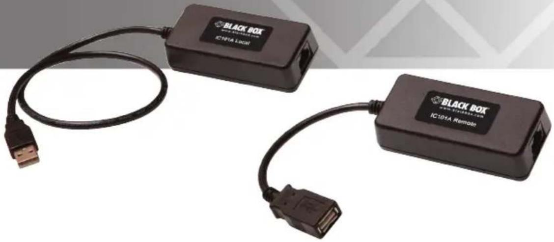
Two black BLACK BOX devices connected by USB cables, one with a USB port and the other with an ICD101A Remote terminal (no text or symbols on the devices themselves)Trademarks Used in this Manual
Black Box and the Double Diamond logo are registered trademarks of BB Technologies, Inc.
Any other trademarks mentioned in this manual are acknowledged to be the property of the trademark owners.
FEDERAL COMMUNICATIONS COMMISSION AND INDUSTRY CANADA RADIO FREQUENCY INTERFERENCE STATEMENTS
This equipment generates, uses, and can radiate radio-frequency energy, and if not installed and used properly, that is, in strict accordance with the manufacturer's instructions, may cause interference to radio communication. It has been tested and found to comply with the limits for a Class A computing device in accordance with the specifications in Subpart B of Part 15 of FCC rules, which are designed to provide reasonable protection against such interference when the equipment is operated in a commercial environment. Operation of this equipment in a residential area is likely to cause interference, in which case the user at his own expense will be required to take whatever measures may be necessary to correct the interference.
Changes or modifications not expressly approved by the party responsible for compliance could void the user's authority to operate the equipment.
This digital apparatus does not exceed the Class A limits for radio noise emission from digital apparatus set out in the Radio Interference Regulation of Industry Canada.
- Specifications....7
- Overview....8
2.1 Introduction....8
2.2 What's Included....8
2.3 Additional Items You Will Need 8
2.4 Hardware Description 9
2.4.1 Local Extender....9
2.4.2 Remote Extender....10
- Installation 11
3.1 Installing the Local Extender Unit.... 11
3.2 Installing the Remote Extender Unit....11
3.3 Connecting the Local Extender to the Remote Extender ..... 12
3.3.1 With Surface Cabling....12
3.3.2 With Premise Cabling....12
3.4 Connecting a USB Device 12
3.5 Checking the Installation....12
- Troubleshooting....13
4.1 Problems/Solutions 13
4.2 Contacting Black Box....14
4.3 Shipping and Packaging....14
- Technical Glossary....15
1. Specifications
| Approvals FCC Part 15 Class A,CE Class A,CES-003 Class A,ESD (EN61000) Criteria A,EFT (EN61000) Criteria A | |
| Current Maximum | current available to USB device at remote extenderunit: 400 mA when Remote Extender is supplied with 600 mA |
| Distance 131 ft. (40 m) | over solid-core CAT5e (or better) cableNOTE: Up to 278 ft. (85 m) may be achieved with low-speedHIDs such as keyboard and mouse. |
| Environmental Operating Temperature:32 to 122° F (0 to 50°C);Storage Temperature:-4 to +158°F (-20 to +70°C);Operating Humidity:20 to 80% relative humidity, noncondensing;Storage Humidity:10 to 90% relative humidity, noncondensing | |
| USB Support USB device:High-speed devices (USB 2.0) at full-speed (USB 1.1) rates,Full-speed devices (USB 2.0 and 1.1),Low-speed devices (USB 2.0 and 1.1);USB hub:Any single chain can include up to 3 USB hubs, dependingon which USB devices are being extended. Extensiondistance will be reduced with each hub added to the system.;USB host: EHCI (USB 2.0) and OHCI/UHCI (USB 1.1) | |
| Connectors Local Extender:(1) USB Type A,(1) RJ-45;Remote Extender:(1) USB Type A,(1) RJ-45 | |
| Dimensions Each unit (local or remote): 0.98"H x 3.34"W x 1.57"D(2.5 x 8.5 x 4 cm) | |
| Weight 0.292 lb. (0.109 kg) | |
2. Overview
2.1 Introduction
The CAT5 USB 1.1 Single-Port Extender enables users to extend USB devices up to 131 feet (40 meters). Extension distances up to 278 feet (85 meters) may be achievable with low-speed HID devices such as keyboards and mice.
2.2 What's Included
- Local Extender
- Remote Extender
- This user's manual
2.3 Additional Items You Will Need
To complete the installation, you will also require the following items that are not included with the product:
- USB 1.1 or 2.0 compatible computer (host computer) with a USB compliant operating system
- USB 1.1 or 2.0 compatible device(s)
- CAT5 Unshielded Twisted Pair (UTP) cable with two RJ-45 connectors (if using surface cabling),
OR
CAT5 cabling with two information outlets and two CAT5 patch cords with RJ-45 connectors (if using premise cabling)
NOTE: All references to CAT5 cable in this document refer to solid-core and represent the minimum requirement.
2.4 Hardware Description
2.4.1 Local Extender
The Local Extender connects to the computer using the upstream USB Type A connector.

natural_image
Black USB device with cable and connector, labeled 'BLACK BOX' and 'IC101A LOGI', shown without any text or symbols on the device body.Figure 2-1. Local extender.
Table 2-1. Local Extender components.
| Number in Figure 2-1 | Type Description | |
| 1 Link port (RJ-45) Accepts RJ-45 connector for CAT5 (or better) cabling. | ||
| 2 Device port | (USB Type A) Used to connect the Local Extender unit to the host computer. | |
2.4.2 Remote Extender
The Remote Extender provides one downstream USB Type A port for a standard USB device. Additional devices may be connected by attaching USB hubs.

Figure 2-2. Remote extender.
Table 2-2. Remote Extender components.
| Number in Figure 2-2 | Type Description | |
| 1 Link port (RJ-45) Accepts RJ-45 connector for CAT5 (or better) cabling. | ||
| 2 Device port (USB Type A) Accepts USB device(s). | ||
3. Installation
Before you can install the product, you need to prepare your site:
- Determine where the computer is to be located and set up the computer.
- Determine where you want to locate the remote USB device(s).
- If you are using surface cabling, the product supports a maximum distance of 131 feet (40 m).
OR
If you are using premise cabling, ensure CAT5 cabling is installed between the two locations, with CAT5 information outlets located near both the computer and the USB device(s), and the total length, including patch cords, is no more than 131 feet (40 m).
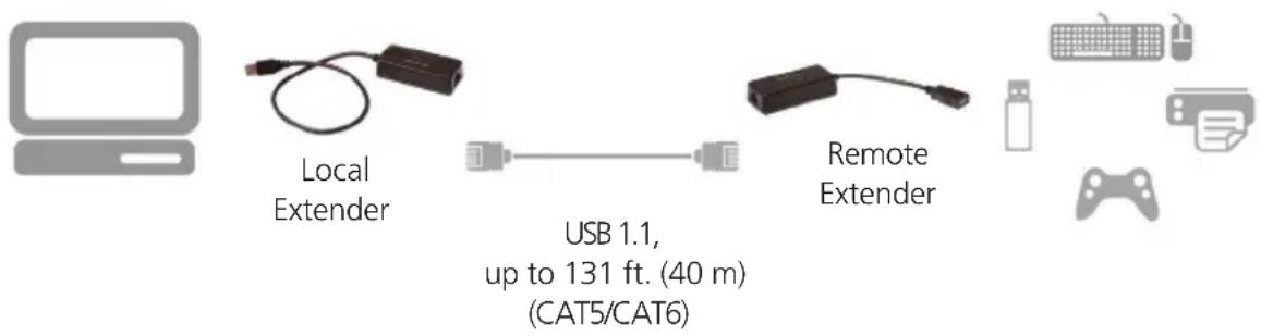
Figure 3-1. Typical installation.
3.1 Installing the Local Extender Unit
-
Place the Local Extender unit near the computer.
-
Plug the USB cable from the Local Extender into an available USB 2.0/1.1 Type A Port on the computer.
3.2 Installing the Remote Extender Unit
- Place the Remote Extender unit near the USB device(s) in the desired remote location.
- Plug in your USB Device.
3.3 Connecting the Local Extender to the Remote Extender
NOTE: Extension length is reduced for each USB hub added to the system. There is a 43.3-foot (13.2-meter) reduction in extension distance for each USB hub added to the system. This includes hubs added on the Local Extender or Remote Extender side.
NOTE: The Extender cannot be daisychained together. A system can have only one Local Extender and one Remote Extender.
3.3.1 With Surface Cabling
-
Plug one end of the CAT5 cabling (not included) into the Link port (RJ-45) on the Local Extender unit.
-
Plug the other end of the CAT5 cabling into the Link port (RJ-45) on the Remote Extender unit.
3.3.2 With Premise Cabling
-
Plug one end of a CAT5 patch cord (not included) into the Link port (RJ-45) on the Local Extender unit.
-
Plug the other end of the patch cord into the CAT5 information outlet near the host computer.
-
Plug one end of the second CAT5 patch cord (not included) into the Link port (RJ-45) on the Remote Extender unit.
-
Plug the other end of the second patch cord into the CAT5 information outlet near the USB device.
3.4 Connecting a USB Device
-
Install any software required to operate the USB device. Refer to the documentation for the USB device, as required.
-
Connect the USB device to the device port on the Remote Extender unit.
3.5 Checking the Installation
NOTE: Check if the USB device is detected by your operating system.
To open System Profiler in OS X: Open Finder, select "Applications," then open the "Utilities" folder and double-click on the "System Profiler" icon.
To open Device Manager in Windows 2000 or XP: Right click "My Computer," then select: "Properties >> Hardware tab >> Device Manager."
To open Device Manager in Windows Vista or Windows 7: Open the "Start" menu, right click on "Computer" then select: "Manage >> Device Manager."
4. Troubleshooting
4.1 Problems/Solutions
This section provides troubleshooting tips. The topics are arranged in the order in which they should be executed, in most situations. If you are unable to resolve the problem after following these instructions, please contact Technical Support for further assistance.
Problem: The USB device does not operate correctly.
Possible Cause:
- The USB device is malfunctioning.
- The computer does not recognize the USB device.
- The application software for the device is not operating.
• The Extender is malfunctioning.
Solution:
- Un-install and re-install the driver for the USB device.
- Update the driver for the USB device.
- Directly connect the USB device to the Host to verify the USB device operates correctly.
- Contact Technical Support.
Problem: The USB device is detected as an "Unknown Device" in the Operating System.
Possible Cause:
- The USB device's timing is outside of the USB 1.1 specification.
• The Extender is malfunctioning.
Solution:
- Connect the Remote Extender to the Local Extender using a patch cable.
- Unplug the Local Extender from the host and wait 15 seconds. Then plug the Local Extender back into the host.
- Contact Technical Support.
Problem:
The USB device is detected as using too much power in the Operating System.
Possible Cause:
- The USB device needs more power than the Extender can support.
- The Host is not providing enough power to the Extender.
Solution:
- Connect the Local Extender to a different USB port on the Host.
- Connect a self-powered USB hub between the Remote Extender and the USB device.
4.2 Contacting Black Box
If you determine that your CAT5 USB 1.1 Single-Port Extender is malfunctioning, do not attempt to alter or repair the unit. It contains no user-serviceable parts. Contact Black Box Technical Support at 724-746-5500 or info@blackbox.com.
Before you do, make a record of the history of the problem. We will be able to provide more efficient and accurate assistance if you have a complete description, including:
- the nature and duration of the problem.
- when the problem occurs.
- the components involved in the problem.
- any particular application that, when used, appears to create the problem or make it worse.
4.3 Shipping and Packaging
If you need to transport or ship your CAT5 USB 1.1 Single-Port Extender:
- Package it carefully. We recommend that you use the original container.
- If you are returning the unit, make sure you include everything you received with it. Before you ship for return or repair, contact Black Box to get a Return Authorization (RA) number.
5. Technical Glossary
Category 5 (CAT5) Network Cabling — Category 5 cable is commonly also referred to as CAT5. This cabling is available in either solid or stranded twisted pair copper wire variants and as UTP (Unshielded Twisted Pair) or STP (Shielded Twisted Pair). UTP cables are not surrounded by any shielding, making them more susceptible to electromagnetic interference (EMI). STP cables include shielding over each individual pair of copper wires that provides better protection against EMI. Category 5 has been superseded by CAT5e cabling, which includes improved data integrity to support high-speed communications.
USB Cables — USB cables have two distinct connectors. The Type A connector is used to connect the cable from a USB device to the Type A port on a computer or hub. The Type B connector is used to attach the USB cable to a USB device.
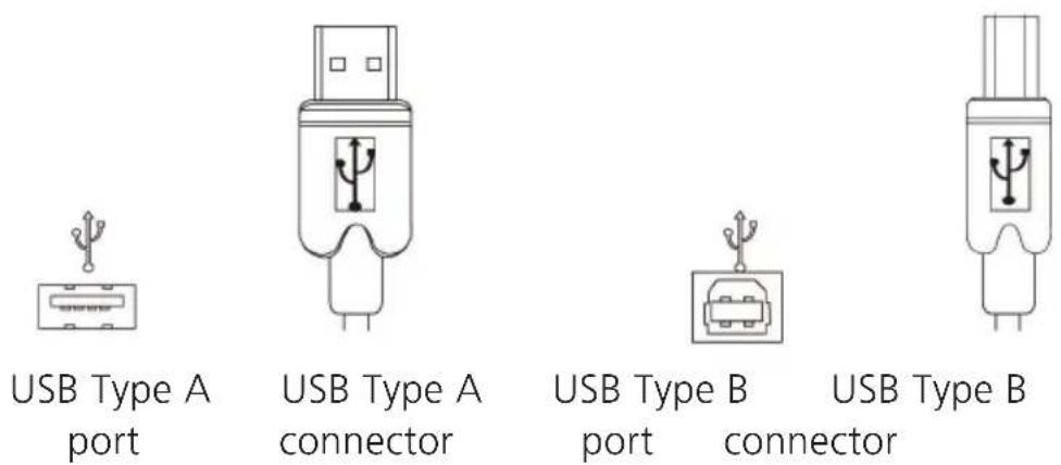
Figure 5-1. USB cables.
RJ-45 — The Registered Jack (RJ) physical interface is what connects the network cabling (CAT5) to the local extender and remote extender. You may use either the T568A scheme (Table 5-1) or the T568B scheme (Table 5-2) for cable termination because the extender uses all four pairs of the cable. RJ-45 connectors are sometimes also referred to as 8P8C connectors.
RJ-45 Pin Positioning —
Table 5-1. T568A wiring.
| Pin Pair Wire Cable Color |
| 1 3 1 White/Green |
| 2 3 2 Green |
| 3 2 1 White/Orange |
| 4 1 2 Blue |
| 5 1 1 White/Blue |
| 6 2 2 Orange |
| 7 4 1 White/Brown |
| 8 4 2 Brown |
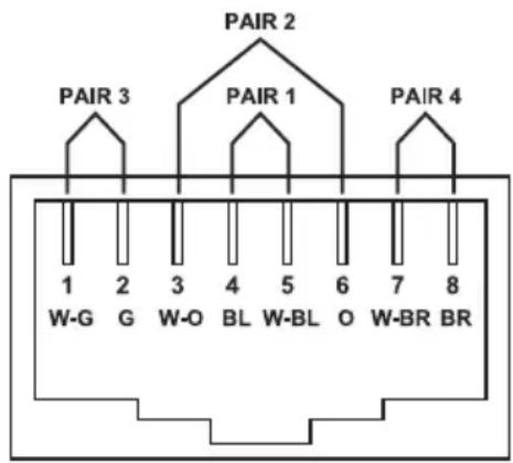
Figure 5-2. T568A connector pinout.
Table 5-2. T568B wiring.
| Pin Pair Wire Cable Color |
| 1 2 1 White/Orange |
| 2 2 2 Orange |
| 3 3 1 White/Green |
| 4 1 2 Blue |
| 5 1 1 White/Blue |
| 6 3 2 Green |
| 7 4 1 White/Brown |
| 8 4 2 Brown |

Figure 5-3. T568B connector pinout.
Black Box Tech Support: FREE! Live. 24/7.
Tech support the way it should be.

natural_image
Close-up portrait of a smiling man wearing a headset (no visible text or symbols)Great tech support is just 30 seconds away at 724-746-5500 or blackbox.com.

BLACK BOX®
NETWORK SERVICES
About Black Box
Black Box provides an extensive range of networking and infrastructure products. You'll find everything from cabinets and racks and power and surge protection products to media converters and Ethernet switches all supported by free, live 24/7 Tech support available in 30 seconds or less.
© Copyright 2013. Black Box Corporation. All rights reserved. Black Box ^® and the Double Diamond logo are registered trademarks of BB Technologies, Inc. Any third-party trademarks appearing in this manual are acknowledged to be the property of their respective owners.
IC101A, version 1
- CAT5 USB 1.1 Single-Port Extender
- Extend USB devices up to 40 meters (131 feet).
- FEDERAL COMMUNICATIONS COMMISSION AND INDUSTRY CANADA RADIO FREQUENCY INTERFERENCE STATEMENTS
- Specifications
- Overview
- Introduction
- What's Included
- Additional Items You Will Need
- Hardware Description
- Local Extender
- Remote Extender
- Installation
- OR
- Installing the Local Extender Unit
- Installing the Remote Extender Unit
- Connecting the Local Extender to the Remote Extender
- With Surface Cabling
- With Premise Cabling
- Connecting a USB Device
- Checking the Installation
- Troubleshooting
- Problems/Solutions
- Possible Cause:
- Solution:
- Problem:
- Contacting Black Box
- Shipping and Packaging
- Technical Glossary
- RJ-45 Pin Positioning —
- BLACK BOX®
- NETWORK SERVICES
- About Black Box
Brand : Black Box
Model : IC101A
Category : USB Drive