LIBATTSMGGIEC - Inverter APC - Free user manual and instructions
Find the device manual for free LIBATTSMGGIEC APC in PDF.

User questions about LIBATTSMGGIEC APC
0 question about this device. Answer the ones you know or ask your own.
Ask a new question about this device
Download the instructions for your Inverter in PDF format for free! Find your manual LIBATTSMGGIEC - APC and take your electronic device back in hand. On this page are published all the documents necessary for the use of your device. LIBATTSMGGIEC by APC.
USER MANUAL LIBATTSMGGIEC APC
Operation and Maintenance Manual
natural_image
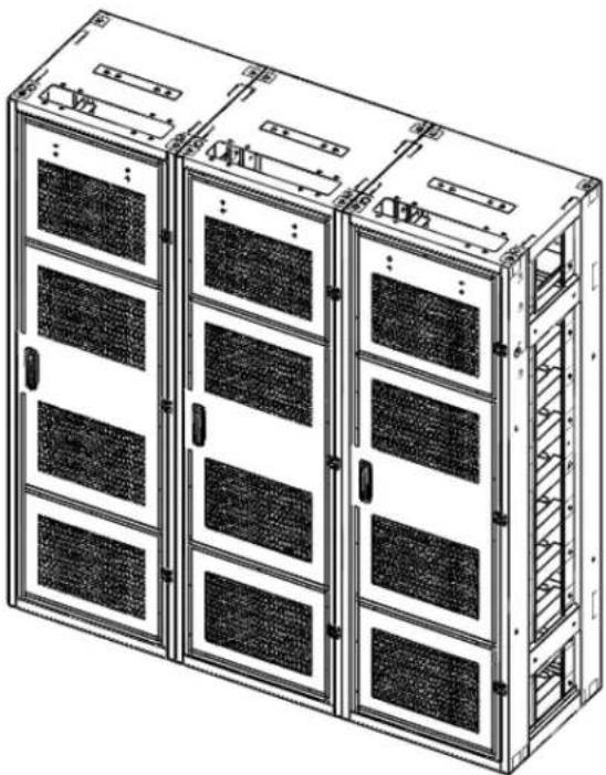
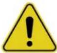
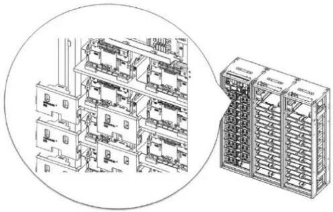
Technical line drawing of a multi-chamber server rack unit (no text or symbols visible)Read this manual carefully before starting to install the battery system. Keep these instructions for future reference.
Copyright © 2016 SAMSUNG SDI Co., Ltd. All rights reserved.
This document contains information that is the property of SAMSUNG SDI Co., Ltd., and provides for the sole purpose of the installation, operation, and maintenance of products of SAMSUNG SDI Co., Ltd. No part of this publication is to be used for any other purpose. It is not to be reproduced, copied, disclosed, transmitted, stored in a retrieval system, or translated into any human or computer language in any form, by any means, in whole or in part, without the prior written consent of SAMSUNG SDI Co., Ltd.
Although every possible effort has been made to ensure the accuracy of this document, SAMSUNG SDI Co., Ltd. assumes no responsibility for errors that may appear herein. The information is subject to change without notice.
Important Safety Instructions
Read and follow these instructions!
The following precautions are intended to ensure your safety and prevent property damage. Before installing this product, be sure to read all safety instructions in this document.
 | DANGER |
| Failure to comply with the instructions with this symbol may result in a serious accident, causing death or severe injury. | |
 | WARNING |
| Failure to comply with the instructions with this symbol may result in a serious accident, causing severe injury. | |
 | CAUTION |
| Failure to comply with the instructions with this symbol may result in minor or moderate injury. | |
 | NOTICE |
| Provides information considered important but not hazard-related. The information relates to property damage. | |
 | Important |
| Indicates valuable tips for optimal installation and operation of the product. | |
General Instructions
Be aware that a battery presents a risk of electric shock including high short-circuit current. Follow all safety precautions while operating the batteries.
- Remove watches, rings, and other metallic items.
- Use tools with insulated handles to avoid inadvertent short circuits.
- Wear rubber gloves and safety boots.
- Do not put tools or any metal parts on the top of the batteries.
- Disconnect the charging source and load before connecting or disconnecting terminals.
- Use proper lifting means when moving batteries and wear all appropriate safety clothing and equipment.
- Batteries must be handled, transported and recycled or discarded in accordance with federal, state and local regulations. Do not dispose of the batteries in a fire because they can explode.
- Do not open or mutilate the batteries.
- Only authorized, properly trained and qualified technicians should perform maintenance.
- Only qualified personnel who are familiar with the batteries and safety precautions should installor maintain the battery system.
- Do not allow unauthorized personnel to contact the batteries.
Safety Precautions
The following precautions are general safety guidelines that should be followed when working with or near the Energy Storage System (ESS). The user should develop complete, site-specific safety parameters and procedures.
- Review and refer to all safety warnings and cautions in this manual before installation.
- Build a clear, permanent, restricted access area around the system.
- Only authorized, properly trained electrical operators should be able to access the system.
The interior of this equipment must be considered a “no-go area except for qualified personnel who are familiar with the batteries and safety precautions.” Consult local codes and applicable rules and regulations to determine permit requirements. If required, mark enclosures appropriately before beginning work.
Personnel and Equipment Warnings
Personnel in contact with the battery system should be aware of the following hazards:
WARNING—SHOCK HAZARD
Do not contact system connectors or terminals. Do not open the enclosure doors unless proper lock out and tag out procedures and related trainings are followed in accordance with local codes and regulations.

WARNING—ARC FLASH HAZARD
All electrical equipment presents an arc flash hazard. There is a serious risk of arc flash relating to any equipment modification, such as opening doors. Serious injuries can occur in arc flash incidents. Appropriate training is required in accordance with local codes and regulations.

WARNING—FIRE HAZARD
Certain faults may cause a fire.
In case of fire involving electrical equipment, use only carbon dioxide fire extinguishers or those approved for use in fighting electrical fires

CAUTION—PINCH POINTS
Multiple pinch-points are present in most system components. Be aware that there is a serious risk of injury while working around and in equipment enclosures.

CAUTION—STATIC SENSITIVE
Electronic devices can be damaged by electrostatic discharge. Proper handling procedures are required. Be sure to wear a grounded anti-static wrist strap and to discharge static electricity by touching a grounded surface near the equipment before touching any system components.
Dangerous Voltages
DANGER
The Electrical Storage System (ESS) is powered by multiple power sources. Hazardous voltages may be present in the equipment even when it does not appear operational. Make sure that you completely understand the cautions and warnings in this manual. Failure to do so may result in serious injury or death. Follow all manufacturer-published safety procedures.
Electrical equipment can present a risk of electrical shock and can cause arc flash. The following precautions must be observed when working on or around electrical equipment:
- Remove watches, jewelry, rings, and other metallic objects.
- Use tools with insulated handles.
- Safety clothing and shoes must comply with local codes and regulations.
Lock Out/Tag Out Guidelines
DANGER
Failure to follow all the applicable lock out/tag out (LOTO) procedures at all times may result in serious injury or death.
With power applied to the ESS, hazardous voltages are present on some components. To prevent death or injury, do not touch any components within the enclosure unless specifically directed to do so. To reduce the risk of electrical shock, make sure that all equipment is properly grounded. For more information, refer to the installation manual.
WARNING

Enclosure doors must remain closed except when access to the enclosure interior is required. Personnel should keep a safe distance from enclosures whenever the equipment is energized. Always comply with local, state, and national lock out/tag out guidelines when working with or near the ESS. The LOTO procedures must meet or exceed the requirements of all guidelines presented in SAMSUNG SDI safety documentation. Follow these steps before entering potentially hazardous areas or beginning work on the ESS:
- Wear protective clothing and shoes. -
- Identify and isolate all power and stored energy sources.
- Apply appropriate LOTO devices. When applying LOTO to the ESS, do not touch anything within the enclosure except as specifically directed in the work procedures.
- Complete the site-specific LOTO procedure and safety checklist before beginning work.
General Warnings
text_image
Seven yellow warning symbols with exclamation marks, arranged verticallyDANGER
When energized, this equipment presents a hazard of electric shock, death, and injury. Only authorized, properly trained personnel who are thoroughly familiar with the equipment and should install, operate, or maintain this equipment.
DANGER
To avoid death, injury, and property damage, follow all safety procedures promulgated by Environmental Health and Safety (EHS) guidelines.
DANGER
To minimize the hazards of electrical shock, death, and injury, approved grounding practices and procedures must be strictly followed.
WARNING
To avoid injury and equipment damage, personnel must adhere to the site protocol concerning working at heights.
WARNING
To avoid personal injury or equipment damage caused by equipment malfunction, only properly and qualified trained personnel should modify any programmable machine.
WARNING
Always ensure that applicable standards and regulations are followed and only properly certified equipment is used as a critical component of a safety system. Never assume that a safety-critical control loop is functioning correctly.
Table of Contents
Important Safety Instructions .... i
General Instructions.... ii
Safety Precautions ...... ii
Personnel and Equipment Warnings ....iii
Dangerous Voltages ....iii
Lock Out/Tag Out Guidelines.... iv
General Warnings.... iv
Table of Contents...... i
Tables......iii
Figures iv
1. About this Manual.... 1
1.1 Purpose .... 1
1.2 Target Audience....1
1.3 Organization 1
1.4 Revision History....2
1.5 Acronyms and Abbreviations ....3
2. Product Description .... 4
2.1 Major Components .... 4
2.1.1 Battery Module (Type A / Type B) 5
2.1.2 Switchgear Assembly 7
2.1.3 SMPS Assembly (Type A / Type B)....10
2.1.4 Rack Frame....13
3. Battery System Operation.... 14
3.1 Indicator LED....14
3.2 Dry Contact Signals 16
3.3 Operation Status....18
3.3.1 Normal Status....21
3.3.2 Minor Protection Status (Alarm) 21
3.3.3 Major Protection Status (Fault) 21
4. Maintenance Checks 22
4.1 Daily Checks....22
4.2 Monthly Checks 22
4.3 Annual Check 22
4.4 Maintenance Checklist....23
5. Troubleshooting, Repair and Replacement 24
5.1 Troubleshooting....27
5.1.1 Overvoltage Protection – Cell (Major Protection) 27
5.1.2 Undervoltage Protection – Cell (Major Protection) 27
5.1.3 Overvoltage Protection – Rack (Major Protection) 28
5.1.4 Undervoltage Protection – Rack (Major Protection)....28
5.1.5 Voltage Imbalance (Minor Protection)....28
5.1.6 Voltage Sensing Error (Minor Protection) 29
5.1.7 Overtemperature Protection (Major Protection)....29
5.1.8 Undertemperature Protection (Minor Protection) 29
5.1.9 Temperature Imbalance (Minor Protection) 29
5.1.10 Overcurrent Protection (Charge) (Major Protection) 30
5.1.11 Overcurrent Protection (Discharge) (Major Protection)....30
5.1.12 Communication Failure (Module Rack) (Minor Protection) 30
5.1.13 Communication Failure (Rack System) (Minor Protection) 31
5.1.14 Communication Failure (System BMS ↔ Monitoring Software) 32
5.1.15 MCCB Failure (Minor Protection) 32
5.1.16 MCCB Sensor Failure (Minor Protection) 32
5.1.17 Current Sensing Error (Minor Protection) 32
5.1.18 Fuse Failure (Minor Protection) 33
5.1.19 BMS Power is Off 33
5.1.20 MCCB Handle Cannot be Set to "On" 33
5.2 Repair Procedures....34
5.2.1 Module BMS Connection Check....34
5.2.2 Switchgear Connection Check 36
5.2.3 SMPS Assembly Connection Check....38
5.2.4 Busbar Connection Check.... 42
5.2.5 Cell Voltage Balancing....43
5.2.6 System Reset 44
5.2.7 MCCB Handle Control....44
5.3 Replacement Procedures 46
5.3.1 Wire Harness Replacement....47
5.3.2 Battery Module Replacement 53
5.3.3 Rack Fuse Replacement 61
5.3.4 Switchgear Replacement....66
5.3.5 SMPS Assembly Replacement....75
6.1 Disposal and Recycling 104
Tables
Table 2-1: Auxiliary Breaker Switch Connector Description....8
Table 2-2: Terminal Block Description....9
Table 2-3: Dry Contact Connector Description .... 11
Table 2-4: TCP/IP Connector Description....12
Table 2-5: AC Terminal Description....12
Table 3-1: Indicator LED Status....14
Table 3-2: Indicated Codes....15
Table 3-3: Dry Contact Connector Description ...... 16
Table 3-4: Dry Contact Operation....17
Table 3-5: Range of Operation 18
Table 3-6. Protective Functions....19
Table 4-1: Maintenance Checklist Template....23
Table 5-1: Recommended Tools and Instruments for Repair and Replacement 24
Figures
Figure 2-1: Front and Rear Views of Battery Module Type A ....5
Figure 2-2: Front and Rear Views of Battery Module Type B 6
Figure 2-3: Front and Rear Views of the Switchgear Assembly....7
Figure 2-4: Front and Rear Views of the Rack BMS Assembly 7
Figure 2-5: Auxiliary Breaker Switch....8
Figure 2-6: Terminal Block Isometric View 8
Figure 2-7: Terminal Block Front / Top View (Cover Open/Closed)....9
Figure 2-8: Front and Rear Views of SMPS Assembly 10
Figure 2-9: Front and Rear Views of the System BMS 11
Figure 2-10: Front View of SMPS Assembly Type A 11
Figure 2-11: Front and Rear Views of a Rack Frame 13
Figure 3-1: Dry Contact Connector Pinout....16
Figure 5-1. System BMS LED 31
Figure 5-2: Signal "IN" and "OUT" Connectors 34
Figure 5-3: Battery Module with Front Cover Removed....35
Figure 5-4: Voltage and Temperature Sensing Connectors....35
Figure 5-5: DC Power Cables from SMPS Assembly Type A to Switchgear 36
Figure 5-6: DC Power Cables from SMPS Assembly Type B to Switchgear 36
Figure 5-7: CAN Signal Cable Connection from SMPS Assembly to Switchgear 37
Figure 5-8: Signal Cabling Examples of Left Alignment of Switchgears 37
Figure 5-9: Termination resistor setting 38
Figure 5-10: DC Power Cables from SMPS Assembly Type A to Switchgear 38
Figure 5-11: DC Power Cables from SMPS Assembly Type B to Switchgear 39
Figure 5-12: CAN Signal Cable Connection from SMPS Assembly to Switchgear Assembly....39
Figure 5-13: Dry Contact Cable Connection to SMPS Assembly 39
Figure 5-14: AC Input Terminals....40
Figure 5-15: AC Input Terminals with Cables Attached 40
Figure 5-16: AC Input Terminals Protective Covers....41
Figure 5-17: Remove the front covers 42
Figure 5-18: Reattach the Front Covers 43
Figure 5-19: Pressing the Reset Button....44
Figure 5-20: MCCB Handle in Trip Position 45
Figure 5-21: MCCB Handle in Off Position 45
Figure 5-22: MCCB Handle in On Position 45
Figure 5-23: Remove Switchgear to Module #1 OUT Signal Cable 47
Figure 5-24: Install Signal Cable Between the Switchgear and Battery Module #1 OUT....48
Figure 5-25: Opening for Cable Installation 48
Figure 5-26: Remove Module to Module Signal Cable 49
Figure 5-27: Install Module to Module Signal Cable 49
Figure 5-28: CAN Wire Harness Between Switchgear Assemblies 50
Figure 5-29: CAN Cable Connection from SMPS Assembly to Switchgear 50
Figure 5-30: MCCB Handle in "OFF" position....51
Figure 5-31: DC Power Cables from SMPS Assembly Type A to Switchgear 51
Figure 5-32: DC Power Cables from SMPS Assembly Type B to Switchgear 51
Figure 5-33: MCCB Handle in "ON" Position 52
Figure 5-34: Battery Module Type A....54
Figure 5-35: Battery Module Type B....54
Figure 5-36: MCCB Handle in "OFF" Position 54
Figure 5-37: Remove Battery Module Front Covers 55
Figure 5-38: Measuring Each Battery Module's Voltage....55
Figure 5-39: Assemble Battery Module Front Covers....56
Figure 5-40: DC Power Supply and Battery Module Connection 56
Figure 5-41: Battery Module Signal Cables 57
Figure 5-42: Battery Module Front Covers....57
Figure 5-43: Busbars on Positive and Negative Terminals 58
Figure 5-44: Pivoting the Guide and Pulling the Battery Module Out....58
Figure 5-45: Inserting the Replacement Battery Module....59
Figure 5-46: Removing the Front Covers....59
Figures
Figure 5-47: Busbars 59
Figure 5-48: Reattaching the Front Cover to the Battery Module 60
Figure 5-49: Connecting the Signal Cables....60
Figure 5-50: MCCB Handle in "ON" Position 60
Figure 5-51: MCCB Handle in "OFF" Position 61
Figure 5-52: Removing Rack Fuse Cover....62
Figure 5-53: Remove the Battery Module Front Covers 62
Figure 5-54: Remove the Bolts from Battery Module Terminals 63
Figure 5-55: Remove the Rack Fuse Assembly 63
Figure 5-56: Rack Fuse Busbar Assembly 63
Figure 5-57: Attach the Replacement Rack Fuse Assembly....64
Figure 5-58: Bolts for the Battery Module Terminals....64
Figure 5-59: Battery Module Front Cover 64
Figure 5-60: Rack Fuse Cover....65
Figure 5-61: MCCB Handle in "ON" Position 65
Figure 5-62: MCCB Handle in "OFF" Position 66
Figure 5-63: DC IN Cable 66
Figure 5-64: CAN Cable to SMPS Assembly....66
Figure 5-65: CAN Cable to Adjacent Rack 67
Figure 5-66: Module Signal Cable 67
Figure 5-67: Battery Module Front Covers....67
Figure 5-68: Bolts on Battery Modules....68
Figure 5-69: Switchgear Assembly Terminal Covers....68
Figure 5-70: Busbars 69
Figure 5-71: P+, P- Terminals....69
Figure 5-72: Screws on Switchgear Assembly 69
Figure 5-73: Screws on Switchgear Assembly Grounding Cable 70
Figure 5-74: Replacing Switchgear....70
Figure 5-75: Screws on Switchgear....70
Figure 5-76: Screws on Switchgear Grounding Cable....71
Figure 5-77: Busbars 71
Figure 5-78: B+, B-, P+, P- Terminal Connections and Terminal Covers .... 72
Figure 5-79: Switchgear to Module Signal Cable....72
Figure 5-80: Switchgear to SMPS Assembly CAN Signal Cable 73
Figure 5-81: Adjacent Rack CAN Signal Cable 73
Figure 5-82: DC Power Cables from SMPS Assembly Type A to Switchgear 73
Figure 5-83: DC Power Cables from SMPS Assembly Type B to Switchgear 74
Figure 5-84: MCCB Handle in "ON" Position 74
Figure 5-85: MCCB Handle in "OFF" Position 75
Figure 5-86: AC Input Terminals....75
Figure 5-87: Cables to the AC Input Terminals....76
Figure 5-88: DC OUT Connection....76
Figure 5-89: BMS CAN Connection....76
Figure 5-90: TCP/IP Connection....77
Figure 5-91: Dry Contact Connection .... 77
Figure 5-92: Unscrew SMPS Assembly....77
Figure 5-93: Unscrew SMPS Assembly Grounding Cable....78
Figure 5-94: Remove the SMPS Assembly ....78
Figure 5-95: Insert the SMPS Assembly....79
Figure 5-96: Screw on the SMPS Assembly....79
Figure 5-97: Screw on the SMPS Assembly Grounding Cable 80
Figure 5-98: DC Power Cables from SMPS Assembly Type A to Switchgear 80
Figure 5-99: DC Power Cables from SMPS Assembly Type B to Switchgear 80
Figure 5-100: BMS CAN Cable from SMPS Assembly to Switchgear 81
Figure 5-101: TCP/IP Cable 81
Figure 5-102: Dry Contact Cable 81
Figure 5-103: AC Input Terminals....82
Figure 5-104: AC Input Terminals with Cables Attached....82
Figure 5-105: AC Input Terminals Protective Cover 83
Figure 5-106: MCCB Handle in "ON" Position 83
Figure 5-107. Battery module 84
Figure 5-108. Battery module with front cover removed 85
Figures
Figure 5-109. Voltage and temperature sensing connectors ....85
Figure 5-110. Remove the two screws 86
Figure 5-111. Remove the Module BMS from battery module....86
1. About this Manual
This section briefly describes the purpose, audience, organization, revision history, and acronyms and abbreviations used in this document.
1.1 Purpose
The purpose of this manual is to provide information for the safe and successful operation and maintenance of the product.
1.2 Target Audience
This manual is intended for system administrators and operators who install, operate, maintenance and configure the product.
1.3 Organization
This manual is composed of the following chapters:
- Chapter 1, "About this Manual" introduces preliminary description about this document.
- Chapter 2, "Product Description" describes the major components of the product.
- Chapter 3, "Battery System Operation" explains the operation modes of the battery system.
• Chapter 4, "Maintenance Check" lists items to inspect daily, monthly, and annually. - Chapter 5, "Troubleshooting" guides the reader through clearing protection modes and replacing components.
1.4 Revision History
| Rev. | Description | Author | Date |
| 0.0 | First Draft (tentative release) | 2016.06.30 | |
| 0.1 | First Release | 2016.07.04 | |
| 0.2 | 3.1 Indicator LED- Power off LED status added3.2 Dry Contact Signals- Added Figure 3.1 | 2016.08.18 | |
| 0.3 | 3.2 Dry Contact Signals- Revised B6, A6 contact | 2016.09.05 | |
| 0.4 | Edited with customer comments | 2016.10.14 | |
| 0.5 | Edited with customer commentsDry contact connector correctedAdded Troubleshooting 5.1.14 | 2016.12.21 | |
| 0.6 | Added document number | 2017.05.22 | |
| 0.7 | 5.3.6 Module BMS Replacement added | 2017.12.16 | |
| 0.8 | 5.3.7 Module Voltage Sensing Wire Replacement and 5.3.8 Module Temperature Sensing Wire Replacement added | 2017.01.08 | |
| Approved By: | ||
| Name | Signature | Date |
| Trusted Reviewers | ||
| Name | Signature | Date |
1.5 Acronyms and Abbreviations
The following acronyms and abbreviations are used in this manual.
| Abbreviations | Full Name |
| AED | Automated External Defibrillator |
| BMS | Battery Management System |
| Comm. | Communication |
| EHS | Environmental Health and Safety |
| ESS | Energy Storage System |
| LOTO | LOCK OUT/TAG OUT |
| OT | Overtemperature |
| OVP | Overvoltage Protection |
| SMPS | Switched Mode Power Supply |
| SOC | State Of Charge |
| SOH | State Of Health |
| SG | Switchgear |
| UT | Undertemperature |
| UVP | Undervoltage Protection |
| UPS | Uninterruptible Power Supply |
2. Product Description
Before operating the battery system, users must be familiar with its components.
2.1 Major Components
Samsung SDI's Lithium Ion Battery System has the following components:
- Module Assembly (Type A / Type B)
- Switchgear Assembly
- Rack BMS Assembly (embedded in the Switchgear)
- Rack Frame
• SMPS Assembly (Type A / Type B) - System BMS (Embedded in the SMPS Assembly)
Refer to the "Product Specification" document for detailed specifications of the components.
2.1.1 Battery Module (Type A / Type B)
The battery module consists of battery cells in 8S1P configuration. Each battery module has a module BMS (Battery Management System). Its specifications are:
• Nominal capacity: 67Ah
• Nominal voltage: 30.40V
• Weight: 17kg (37.48 lb.)
- Dimensions, L x W x H: 414.00 mm x 216.00 mm x 163.00 mm (16.30 in. x 8.50 in. x 6.42 in.)
There are two types of 8S1P Battery Modules. The model number for each type is determined by the position of polarity. Type A's positive (+) terminal is on the right side viewed from the front. The positive terminal for Type B is on the left.
Following are front and rear views of module assemblies.

text_image
Battery Module Type A (Isometric Front/Rear) Battery Module Type A (Front) SAMSUNG SDI ESSFigure 2-1: Front and Rear Views of Battery Module Type A
2. Product Description

text_image
Battery Module Type B (Isometric Front/Rear) Battery Module Type B (Front) SAMSUNG SDI ESSFigure 2-2: Front and Rear Views of Battery Module Type B
2.1.2 Switchgear Assembly
The Switchgear Assembly consists of a protective circuit and a rack BMS. It is connected to the UPS using the positive and negative power terminals on the front of switchgear.
- Fuse: 500A
• MCCB UL/CE: 600A
• Switchgear Weight: 15 kg (33.07 lb.) - Switchgear Dimensions, L x W x H: 583.00 mm x 235.00 mm x 411.00 mm (22.95 in. x 9.25 in. x 16.18 in.)
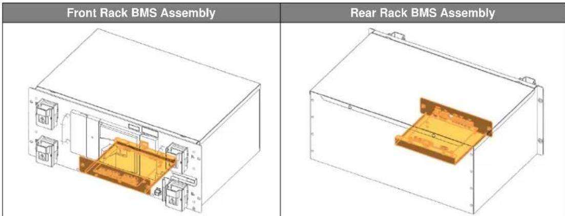
Following are front and rear views of the Switchgear Assembly and Rack BMS Assembly.

text_image
Front Switchgear Assembly Rear Switchgear AssemblyFigure 2-3: Front and Rear Views of the Switchgear Assembly
text_image
Front Rack BMS Assembly Rear Rack BMS AssemblyFigure 2-4: Front and Rear Views of the Rack BMS Assembly
2. Product Description
The switchgear provides an auxiliary breaker switch that can be connected to an external building monitoring system.

text_image
Technical diagram of an electronic device rear panel with labeled components and warning symbolsFigure 2-5: Auxiliary Breaker Switch
Table 2-1: Auxiliary Breaker Switch Connector Description
| Item | Part Name | Description |
| Connector | J21SPM-04V-KX | - |
| Harness Housing | J21SF-04V-KX-L | - |
| Harness Terminal | SJ2F-01GF-P1.0 | AWG 20~24 |
| Pin No. | Pin Name | Function |
| 1 | Normally Open | |
| 2 | Common | |
| 3 | Normally Closed | |
| 4 | - |
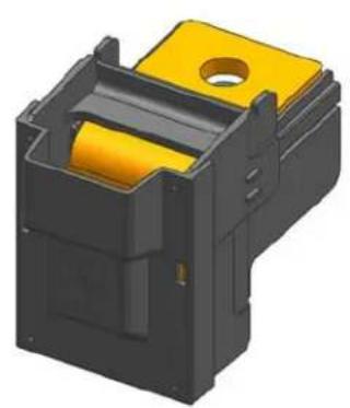
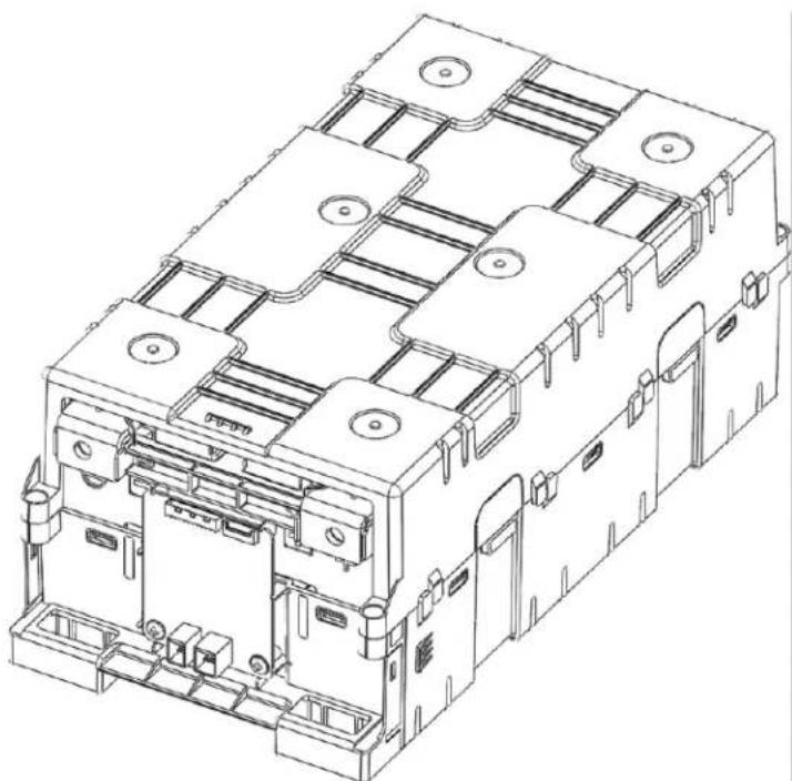
P+ and P- terminal blocks connect to the DC link from the UPS. Cable and lug terminals should be sized according to the conductive piece of the terminal block's size and material.
natural_image
3D rendering of a black plastic enclosure with yellow internal components and a circular top (no text or symbols)Figure 2-6: Terminal Block Isometric View
2. Product Description
| Top View | Front View | |
| COVER OPEN | 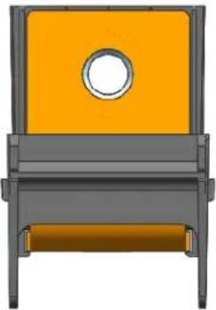 |  |
| COVER CLOSED |  |  |
Figure 2-7: Terminal Block Front / Top View (Cover Open/Closed)
Table 2-2: Terminal Block Description
| Item | Detail | Description |
| Conducting Material | Cu | C1100 |
| Insulating Material (Guide) | PA66 | GF25% |
| Insulating Material (Cover) | PC | |
| Conductive Area | 32.5mm x 40.0mm | |
| Rated Current | 473A | Calculated in accordance with DIN 43670 MELSON & BOTH equation |
2.1.3 SMPS Assembly (Type A / Type B)
The system BMS Assembly provides data to the external systems (i.e., building management system, UPS, etc.) while controlling and monitoring all connected Rack BMS's.
There are two types of SMPS Assemblies. The model number for each type is classified by whether a System BMS is included. Type A has a System BMS; Type B does not.
- Weight:
Type A and Type B: 5 kg (11.02 lb.)
- Dimensions (L x W x H): 397.00 mm x 338.00 mm x 86.00 mm (15.63 in. x 13.31 in. x 3.39 in.)
Below are views of the front and rear of the SMPS Assembly.
| SMPS Assembly (Isometric Front) | SMPS Assembly (Isometric Rear) |
| Type A (with System BMS) | |
| Type B (without System BMS) | |
Figure 2-8: Front and Rear Views of SMPS Assembly
2. Product Description
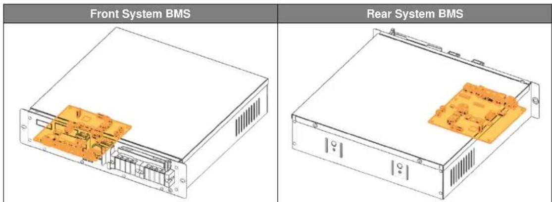
text_image
Front System BMS Rear System BMSFigure 2-9: Front and Rear Views of the System BMS
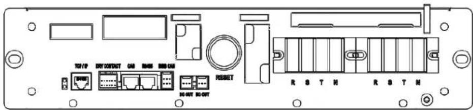
text_image
TCP/IP DRY CONTACT CAS R406 RBB CAS RESET DC-OUT DC-OUT R S T N R S T NFigure 2-10: Front View of SMPS Assembly Type A
The SMPS Assembly provides these communication protocols: RS485, TCP/IP and dry contact.
Table 2-3: Dry Contact Connector Description
| Item | Part Name | Description |
| Connector | S12B-J11DK-TXR | JST |
| Harness Housing | J11DF-12V-KX | JST |
| Harness Terminal | SF1F-21T-P0.6 | AWG 18~22 |
| Pin No. | Pin Name | Function |
| 1A | DRY CONTACT 0 NC | Refer to Table 3-3: Dry Contact Connector Description for functions. |
| 2A | DRY CONTACT 1 COM | |
| 3A | DRY CONTACT 1 NO | |
| 4A | DRY CONTACT 2 NC | |
| 5A | - | |
| 6A | DRY CONTACT IN- (GND) | |
| 1B | DRY CONTACT 0 COM | |
| 2B | DRY CONTACT 0 NO | |
| 3B | DRY CONTACT 1 NC | |
| 4B | DRY CONTACT 2 COM | |
| 5B | DRY CONTACT 2 NO | |
| 6B | DRY CONTACT IN+ |
Table 2-4: TCP/IP Connector Description
| Item | Part Name | Description |
| Connector | VS-08-BU-RJ45/LP-1 | PHOENIX CONTACT |
| Harness Housing | RJ45 | - |
| Harness Terminal | RJ45 | - |
| Pin No. | Pin Name | Function |
| 1 | TX+ | |
| 2 | TX- | |
| 3 | RX+ | |
| 4 | GND | |
| 5 | GND | |
| 6 | RX- | |
| 7 | GND | |
| 8 | GND |
Table 2-5: AC Terminal Description
| Item | Part Name | Description |
| Terminal Block | SL3T-4P | Seoil Electronics |
| Terminals | Ring terminal | 320 ~ 575VAC, 6A |
| Pin No. | Pin Name | Function |
| 1 | L1 | 3 Phase AC Input, L1 |
| 2 | L2 | 3 Phase AC Input, L2 |
| 3 | L3 | 3 Phase AC Input, L3 |
| 4 | PE | PE |
2.1.4 Rack Frame
The Rack Frame is used to mount modules and the Switchgear and SMPS Assemblies. It facilitates grounding the installed components.(Grounding cable/busbar for the Rack Frame is necessary for the Switchgear and SMPS Assemblies because they are grounded to the Rack Frame when installed. The ground cable must be prepared for grounding the Rack Frame to earth.)
• Weight: 190 kg (418.9 lb.)
- Dimensions (L x W x H): 650 mm x 600 mm x 2055 mm (25.59 in x 23.62 in x 80.90 in)
Below are front and rear views of the Rack Frame.

text_image
Front Rack Frame Rear Rack FrameFigure 2-11: Front and Rear Views of a Rack Frame
3. Battery System Operation
The battery system for a UPS is designed to be always on. The UPS and the critical load must be set up so that the battery system's maximum allowable voltage and current are not exceeded.
3.1 Indicator LED
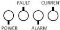
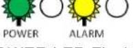
Four indicator LED's on the front of the Switchgear Assembly in each rack displays the status of the battery system per string. Table 3-1 shows each LED's color and the battery status indicated.
Table 3-1: Indicator LED Status
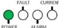
| Items | POWER(Green) | FAULT(Red) | ALARM(Yellow) | CURRENT(Green) |
| Location | 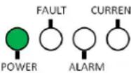 | 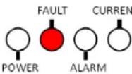 | 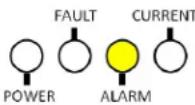 | 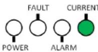 |
| Status | On : MCCB OffOff : Power OffBlink : MCCB On | On : N/AOff : No MajorProtectionBlink : MajorProtection | On : N/AOff : No MinorProtectionBlink : MinorProtection | On : DischargeOff : IdleBlink : Charge |
Depending on the battery system's operating conditions, each indicator LED may be on, blinking or off. Table 3-2 shows the LED indication for the battery status.
Table 3-2: Indicated Codes
| LED Status | Battery Status | Remarks |
 All LED's Off All LED's Off | BMS Power Off | MCCB Off |
 POWER LED Steady POWER LED Steady | Normal | MCCB Off |
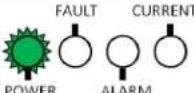 POWER LED Flashing POWER LED Flashing | Normal | MCCB On |
 POWER LED FlashingCURRENT LED Steady POWER LED FlashingCURRENT LED Steady | Normal | Discharge |
 POWER ALARMPower LED FlashingCUI Flashing POWER ALARMPower LED FlashingCUI Flashing | Normal | Charge |
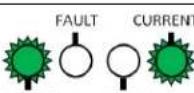
 POWER ALARMP. POWER ALARMP. 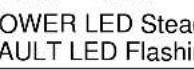 dyF. ng dyF. ng | Major ProtectionMCCB Tripped | Overvoltage ProtectionUndervoltage ProtectionOvertemperature ProtectionOvercurrent Protection |
 POWER LED FlashingALARM LED Flashing POWER LED FlashingALARM LED Flashing | Minor ProtectionMCCB On | Voltage Imbalance ErrorVoltage Sensing ErrorUndertemperature ProtectionTemperature Imbalance Error |
3.2 Dry Contact Signals
Dry contact signals are sent from the System BMS in the SMPS Assembly to let the UPS know the status of the battery system. Three Form-C output channels send signals for major protection, minor protection, and charge stop request. One input channel receives a signal to trip the MCCB when requested from the UPS.
Table 3-3: Dry Contact Connector Description
| Item | Part Name | Description |
| Connector | S12B-J11DK-GWXR | JST |
| Harness Housing | J11DF-12V0KX-L | JST |
| Harness Terminal | SF1F-21GC-P0.6 | AWG 18~22 |
| Pin No. | Pin Name | Function |
| B1 | Major Common | Overvoltage ProtectionUndervoltage ProtectionOvertemperature ProtectionOvercurrent Protection |
| A1 | Major Normally Closed | |
| B2 | Major Normally Open | |
| A2 | Minor Common | Voltage Imbalance ErrorVoltage Sensing ErrorUndertemperature ProtectionTemperature Imbalance Error |
| B3 | Minor Normally Closed | |
| A3 | Minor Normally Open | |
| B4 | MCCB Status Common | All MCCB's are Off : A4, B4 are closed.One of the MCCB's is on : B5, B4 are closed. |
| A4 | MCCB Status Normally Closed | |
| B5 | MCCB Status Normally Open | |
| A5 | Reserved | — |
| B6 | Input | Set Condition: UPS opens B6, A6 contacts for more than 3 seconds.Action : Battery MCCB Trip |
| A6 | GND |

flowchart
graph LR
    A1["B1"] --> C["Process Chamber"]
    B1["B1"] --> C
    C --> D["A6"]
    C --> E["B6"]
Figure 3-1: Dry Contact Connector Pinout
Table 3-4: Dry Contact Operation
| Battery Status | MAJOR | MINOR | MCCB Status | ||||||
| B1 | A1 | B2 | A2 | B3 | A3 | B4 | A4 | B5 | |
| Normal Status | COM | Open | Close | COM | Open | Close | COM | Open | Close |
| Major Protection | COM | Close | Open | COM | Open | Close | COM | Close | Open |
| Minor Protection | COM | Open | Close | COM | Close | Open | COM | Open | Close |
| MCCB Off | COM | Close | Open | COM | Open | Close | COM | Close | Open |
| BMS Power Off | COM | Close | Open | COM | Close | Open | COM | Close | Open |
3.3 Operation Status
Refer to the table below for typical and maximum state of charge and discharge conditions to keep the battery system in normal operation.
Table 3-5: Range of Operation
| No. | Item | Specification^1 | Specification^2 | Remarks |
| 1 | Nominal Capacity | 34.6kWh | 32.6kWh | 1/3C@R.T |
| 2 | Nominal Voltage^3 | 516.8VDC | 486.4VDC | 3.8V/Cell |
| 3 | Maximum Voltage^3 | 571.2VDC | 537.6VDC | 4.2V/Cell |
| 4 | Discharging Method | Constant Power | ||
| End of Discharge Voltage^3 | 384VDC | 384VDC | 3.0V/Cell | |
| Standard Discharging Current | 22.3A | 1/3C@R.T | ||
| Maximum Continuous Discharge Power | 184kW | 173kW | ||
| Maximum Discharge Current | 600A | 1-Second Pulse | ||
| 5 | Charging Method | Floating | ||
| Floating Charge Voltage | 571.2VDC | 537.6VDC | 4.2V/Cell | |
| Standard Charge Current | 22.3A | 1/3C | ||
| Maximum Charge Current | 250A | 2-Second Pulse | ||
| 6 | Recommended Operation Temperature | 23°C ±5°C | Ambient | |
| 7 | Storage Temperature | 0 ~ 40°C | ||
| 8 | Storage Humidity | Less than 60% RH | Non-Condensing | |
| 9 | Storage Period^4 | Less than 6 Months | ||
When the operating limits of the battery system are exceeded, protective measures are taken autonomously to protect the system from failure. The following table lists the protective functions and their actions.
Table 3-6. Protective Functions
| No | Items | Level | Set Condition | Time (Sec) | MCCB | Release Condition | Time (Sec) | MCCB |
| 1 | Overvoltage Protection - Cell | Major | Max Cell ≥ 4.28V | 5 | OFF | Max Cell < 4.25V & Reset | 5 | ON |
| 2 | Undervoltage Protection - Cell | Major | Min Cell ≤ 2.5V | 3 | OFF | Min Cell > 2.70V& Reset | 3 | ON |
| 3 | Overvoltage Protection - Rack ^1 | Major | Rack Voltage ≥ 582.08V | 5 | OFF | Rack Voltage < 578V & Reset | 5 | ON |
| Overvoltage Protection - Rack ^2 | Major | Rack Voltage ≥ 547.84V | 5 | OFF | Rack Voltage < 544V & Reset | 5 | ON | |
| 4 | Undervoltage Protection - Rack1 | Major | Rack Voltage ≤ 340 | 3 | OFF | Rack Voltage > 367.2V & Reset | 3 | ON |
| Undervoltage Protection - Rack2 | Major | Rack Voltage ≤ 320 | 3 | OFF | Rack Voltage > 345.6V & Reset | 3 | ON | |
| 5 | Voltage Imbalance | Minor | Max Cell ≥ 3.50V & △ Vcell ≥ 300mV | 5 | ON | Max Cell ≥ 3.50V & △ Vcell < 50mV & Reset | 5 | ON |
| 6 | Voltage Sensing Error1 | Minor | | Rack V - Cell Sum V| ≥40.8V | 10 | ON | | Rack V - Cell Sum V| < 20.4V & Reset | 3 | ON |
| Voltage Sensing Error2 | Minor | | Rack V - Cell Sum V| ≥38.4V | 10 | ON | | Rack V - Cell Sum V| < 19.2V & Reset | 3 | ON | |
| 7 | Overtemperature Protection | Major | Max Temp ≥ 75°C | 3 | OFF | Max Temp < 65°C & Reset | 3 | ON |
| 8 | Undertemperature Protection | Minor | Min Temp ≤ 0°C | 3 | ON | Min Temp > 5°C & Reset | 3 | ON |
| 9 | Temperature Imbalance | Minor | Max Cell T - Min Cell T ≥ 40°C | 30 | ON | Max Cell T - Min Cell T < 20°C & Reset | 3 | ON |
| 10 | Overcurrent Protection (Charge) | Major | Level2 Current ≥ 250A | 2 | OFF | |Current| < 10A & Reset | 3 | ON |
| Major | Level1 Current ≥ 200A | 60 | OFF | |Current| < 10A & Reset | 3 | ON | ||
| 11 | Overcurrent Protection (Discharge) | Major | Level4 |Current| ≥ 600A | 1 | OFF | |Current| < 10A & Reset | 3 | ON |
| Major | Level3 |Current| ≥ 540A | 10 | OFF | |Current| < 10A & Reset | 3 | ON | ||
| Major | Level2 |Current| ≥ 495A | 30 | OFF | |Current| & Reset | 3 | ON | ||
| Major | Level1 |Current| ≥ 470A | 60 | OFF | |Current| & Reset | 3 | ON | ||
| 12 | Communication Failure (Module ↔ Rack) | Minor | No Communication | 30 | ON | Communication & Reset | - | ON |
| 13 | Communication Failure (Rack ↔ System ) | Minor | No Communication | 30 | ON | Communication & Reset | - | ON |
- Battery System Operation
| No | Items | Level | Set Condition | Time (Sec) | MCCB | Release Condition | Time (Sec) | MCCB |
| 14 | SW Failure - MCCB | Minor | MCCB OFF & |Current| ≥ 2.4A | 3 | ON | (MCCB OFF & (|Current| < 2.4A) & Reset | - | ON |
| 15 | SW Sensor Failure - MCCB | Minor | MCCB Contact ON = MCCB Trip ON | 3 | ON | (MCCB Contact ≠ MCCB Trip) & Reset | - | ON |
| 16 | Current Sensing Error | Minor | No Communication with Current IC | 3 | ON | Communication with Current Sensing IC | - | ON |
| 17 | Fuse Failure | Minor | Fuse Blown | 10 | ON | Replace Fuse & Reset | - | ON |
3.3.1 Normal Status
In normal status, the battery system is available for charge or discharge. The system operator must follow the guidelines below to ensure safe and optimal performance from the battery.
- The battery must be fully charged to power the critical load for the duration of the backup time.
- After a full discharge at maximum continuous power, cool the battery for at least 12 hours before recharging it. Immediate recharging after a full discharge at a recharging current higher than the specified standard charging current may increase the battery cell temperature to overtemperature protection. For optimal performance, delay recharging until the battery temperature returns to room temperature ± 3^ .
- Immediate recharging after a full discharge at maximum continuous power may degrade the battery performance.
3.3.2 Minor Protection Status (Alarm)
When a minor protection (alarm status) occurs, the battery system will send a message to the UPS or other systems and request that all charge or discharge operation be stopped until the problem is corrected. Battery system will not be disconnected in minor protection status to maximize the battery's availability. Refer to Section 5 "Troubleshooting" for solutions to minor protection status.
3.3.3 Major Protection Status (Fault)
If the system detects a major protection (fault status), it will trip the MCCB to disconnect the battery system from the UPS to prevent damage to the battery. Measures must be taken to clear the major protection status and return the battery system to normal status. Personnel must be on-site to return the MCCB from “trip” to “on” position after returning the system status to normal. Refer to Section 5 “Troubleshooting” for details on solutions to major protection status.
4. Maintenance Checks
The battery system components are designed to be free of regular maintenance. Regular inspection of components and power connections are recommended to ensure proper performance. Scheduled checks of the battery system are recommended but not mandatory for optimal performance. Refer to 3.3 Operation Status and Table 3-5: Range of Operation for the battery system's operating conditions.
4.1 Daily Checks
Following is a list of items to be checked daily.
- Rack voltage should be in its floating charge voltage.
• Cell voltage range should be within 300mV. - MCCB must be on for all racks.
• There must be no alarms or faults. - Maintaining room temperature and humidity according to the range of operation..
4.2 Monthly Checks
Personnel should visually inspect the battery system monthly and review log data about the battery and its operating environment.
- Battery should have no visible damage (rust, bent structure, damaged or missing cables or busbars, etc.)
- Check the recorded data of the battery system for the voltage and current readings.
- Check the date and time of charge and discharge cycles.
- Check whether any alarms or faults have been triggered.
4.3 Annual Check
A trend analysis of the recorded data (battery and environment) is recommended.
4.4 Maintenance Checklist
Refer to the following checklist template for scheduled checks. Detailed recordings may be necessary depending on the level of maintenance required by the user. Use Table 3-5: Range of Operation to check the criteria for each item.
Table 4-1: Maintenance Checklist Template
| Items | Criteria | Location | Schedule | Result |
| Battery Status | 1. Battery voltagea) Rack voltage checkb) Cell voltage check (max/min difference)2. Alarm or faults: No alarms or faults set3. MCCB status: All on | Control room | Daily | |
| 1. Alarm or protection: No alarms or protections setCheck the indicator LED's in each rack2. MCCB status: All onCheck the position of the MCCB handle | On-Site | Weekly | ||
| 1. Visual Inspection: check for physical damages(rust, bent structure, damaged or missing cables, etc.) | On-Site | Monthly | ||
| Environment | Temperature (measured from facility's HVAC unit or other measurement devices) | Control Roomor On-Site | Daily | |
| Humidity (measured from facility's HVAC unit or other measurement device) | Daily | |||
| Recorded Data | 1. Recorded voltage and current2. Date and time of charge and discharge cycles3. Number of alarms and faults recorded | Control Room | Monthly | |
| 1. Recorded voltage and current2. Date and time of charge and discharge cycles3. Number of alarms and faults recorded4. Record of temperature and humidity (measured from facility's HVAC unit or other measurement device) | Control Room | Annual |
5. Troubleshooting, Repair and Replacement
Users must operate the battery system within its specified range of operating conditions. Refer to the "Product Specification" for details.
If the battery system is not operated under the specified conditions, it may display protective modes depending on conditions. Users should familiarize themselves with the types of protective modes and the battery system's behavior during these modes. Dry contact signals from the System BMS and indicator LED's on the front of each switchgear displays the status of the battery system. Users can quickly and easily determine the battery system's status from a centralized monitoring location using the dry contact signals or perform an on-site examination using the indicator LED's. Detailed status of the battery system can be examined by using additional monitoring software.
When additional examination is necessary, some tools and instruments may be required. Refer to the installation manual and Table 5-1 "Recommended Tools and Instruments for Repair and Replacement" for the list of tools that may be needed and instructions on how to use them.
If repair or replacement is required, refer to the installation manual for safety guidelines and basic information on disassembly and reassembly of components.
Table 5-1: Recommended Tools and Instruments for Repair and Replacement
| No. | Items | Use | Appearance |
| 1 | Power Screwdriver/Drill (Maximum torque: 26Nm [270 kgf cm]) | Fastening Switchgear and SMPS assemblies to the rack frames (5.1–6.1Nm [50–60 kgf cm]) |  |
| 2 | Phillips Screwdriver or Bit (M5 Tip) | Fastening Switchgear and SMPS assemblies to the rack frames |  |
| 3 | Box Cutter | Opening boxes |  |
| 4 | Forklift | Moving pallets of modules and switchgears |  |
| 5 | Insulated Torque Wrench | Installing high-voltage cable (10~50 Nm [100 ~ 500 kgf cm]) | 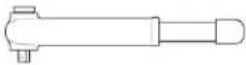 |
| 6 | Insulated Sockets (13 mm, 17mm and 19mm) | Installing power cables and busbars | 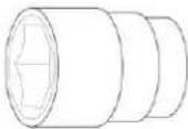 |
- Troubleshooting, Repair and Replacement
| No. | Items | Use | Appearance |
| 7 | Insulated Extension Bar for Sockets | Installing a power cable |  |
| 8 | Battery Tester | Measuring battery modules' voltage and internal impedance |  |
| 9 | Digital Multimeter | Measuring battery string's voltageProbes must be rated for 600V DC or above | 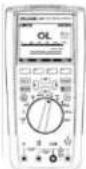 |
| 10 | DC Ammeter (Clamp Meter) | Measuring battery string's currentMust be rated for DC 1000A or above | - |
| 11 | Controllable DC LoadRecommended Specifications1) Input DC 40V or above2) 1kW or above3) Controllable with 10mVresolution or less4) CV discharge available | Discharging replacement battery module | - |
| 12 | Controllable DC Power SupplyRecommended specifications1) Output DC 40V or above2) 1kW or above3) Controllable with 10mVresolution or less4) CC-CV charge available | Charging replacement battery module | - |
| 13 | ComputerMicrosoft® Windows® 7 SP1(English) or later recommended | Running battery monitoring software |  |
- Troubleshooting, Repair and Replacement
| No. | Items | Use | Appearance |
| 14 | Rack BMS ID Writer Cable Use with computer | Battery monitoring software | 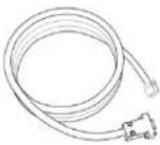 |
| 15 | IXXAT USB-to-CAN V2 Use with computer | Battery monitoring software | 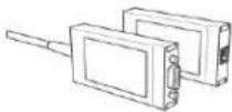 |
5.1 Troubleshooting
To determine the status of the battery system, users must use additional battery status monitoring software to examine the protection mode. Refer to the installation manual about using the monitoring software. Also, refer to Section 3.3 "Operation Status" for set and release conditions for each protection mode. Once the user knows the protection mode, refer to the following sections for solutions.
5.1.1 Overvoltage Protection – Cell (Major Protection)
| Possible Problem | Solution |
| Overcharged Cell | - Press the reset switch in SMPS Assembly and see if it clears the protection.- Check the UPS settings for floating charge voltage. It must be set at 4.2V per cell (i.e., for 136S system, 571.2V must be set as floating charge voltage and for 128S system, 537.6V must be set as floating charge voltage)- Check the dry contact signal cable for “charge stop” and see whether the “charge stop” signal is correctly received by the UPS.- Check the actual cell voltage data using monitoring software and see if there is a cell voltage reading significantly higher than other battery cells. If so, cell balancing is required. Refer to troubleshooting for voltage imbalance.- If the problem persists, the module with the overcharged cell may have to be replaced. |
| Defective Wiring | - Remove the front cover of the module and check the Module BMS wiring.- Press the reset switch in SMPS Assembly and see if it clears the protection. |
| Loose Busbar Installation | - Check the torque of the module and switchgear busbars.- Retighten any loose bolts. |
| Measurement Error | - Press the reset switch in SMPS Assembly and see if it clears the protection.- Check the actual cell voltage data using monitoring software.- Replace the Module BMS if the cell voltage is incorrect.- If the problem persists, replace the battery module. |
5.1.2 Undervoltage Protection – Cell (Major Protection)
| Possible Problem | Solution |
| Deep-Discharged Cell | - Press the reset switch in the SMPS Assembly and see if it clears the protection.- Check the UPS settings for the end-of-discharge voltage. It must be set at 3.0V per cell (i.e., for 136S system, 408V must be set as the end-of-discharge voltage and for 128S system, 384V must be set as end of discharge voltage).- Check the actual cell voltage data using monitoring software and see if there is a cell voltage reading significantly lower than for other battery cells. If so, cell balancing is required. Refer to the Troubleshooting Section 5.2.5 “Cell Voltage Balancing.” |
| Defective Wiring | - Remove the Battery Module’s front and check the Module BMS wiring.- Press the reset switch in the SMPS Assembly and see if it clears the protection. |
| Loose Busbar | - Check the torque of the module and switchgear busbars.- Retighten any loose bolts. |
| Measurement Error | - Press the reset switch in SMPS Assembly and see if it clears the protection.- Check the actual cell voltage data using monitoring software.- Replace the Module BMS if the cell voltage is incorrect.- If the problem persists, replace the battery module. |
5.1.3 Overvoltage Protection – Rack (Major Protection)
| Possible Problem | Solution |
| Overcharged Cell | - Check the UPS settings for floating charge voltage. It must be set at 4.2V per cell (i.e., for 136S system, 571.2V must be set as floating charge voltage and for 128S system, 537.6V must be set as floating charge voltage).- Check the dry contact signal cable for “charge stop” and see if the “charge stop” signal is correctly received by the UPS.- Check the actual cell voltage data using monitoring software and see if there is a cell voltage reading significantly higher than for other battery cells. If so, cell balancing is required. Refer to Troubleshooting Section 5.2.5 “Cell Voltage Balancing.”- If the problem repeats, the Battery Module with the overcharged cell may have to be replaced. |
| Loose Busbar | - Check the torque of the module and switchgear busbars.- Retighten any loose bolts. |
| Measurement Error | - Check the actual rack voltage data using monitoring software.- Replace the switchgear if the rack voltage readings are incorrect. |
5.1.4 Undervoltage Protection – Rack (Major Protection)
| Possible Problem | Solution |
| Deep-Discharged Cell | - Check the UPS settings for end of discharge voltage. It must be set at 3.0V per cell.(i.e., for 136S system, 408V must be set as end-of-discharge voltage.and for 128S system, 384V must be set as the end-of-discharge voltage).- Check the actual cell voltage data using monitoring software and see if there is a cell voltage reading significantly lower than for other battery cells. If so, cell balancing is required. Refer to Troubleshooting Section 5.2.5 “Cell Voltage Balancing.” |
| Loose Busbar | - Check the torque of the module and switchgear busbars.- Retighten any loose bolts. |
| Blown Fuse | - Check whether the “fuse failure” alarm is set.- Check the status of the rack fuse.- Replace any blown fuse and reset the system. |
| Measurement Error | - Check the actual rack voltage data using monitoring software- Replace the switchgear if the rack voltage is incorrect. |
5.1.5 Voltage Imbalance (Minor Protection)
| Possible Problem | Solution |
| Imbalanced Cell | - Check the actual cell voltage data using monitoring software and see if there is a cell voltage reading significantly higher or lower than for other battery cells. If so, cell balancing is required. Refer to Troubleshooting Section 5.2.5 “Cell Voltage Balancing.” |
| Loose Busbar | - Check the torque of the module and switchgear busbars.- Retighten any loose bolts. |
| Defective Wiring | - Remove the front cover of the module and check the Module BMS wiring.- Press the reset switch in the SMPS Assembly and see if it clears the protection. |
| Measurement Error | - Check the actual cell voltage data using monitoring software- Replace the Module BMS if the cell voltage is incorrect.- If the problem persists, replace the battery module. |
5.1.6 Voltage Sensing Error (Minor Protection)
| Possible Problem | Solution |
| Defective Wiring | - Remove the module's front cover and check the Module BMS wiring.- Press the reset switch in the SMPS Assembly and see if it clears the protection. |
| Loose busbar | - Check the torque of the module and switchgear busbars.- Retighten any loose bolts. |
| Measurement Error | - Check the actual cell voltage data using monitoring software.- Check the actual rack voltage data using monitoring software.- Measure the rack voltage and each module's voltage using a digital multimeter and compare the readings to the data obtained from the monitoring software. To measure the rack's voltage, a multimeter with proper probe rating must be used.- If module voltage reading is not correct, determine which module has the incorrect voltage and check its Module BMS connection. If the problem persists, replace the module BMS.- If the problem persists, the module must be replaced.- Replace the Switchgear if the rack voltage is incorrect. |
5.1.7 Overtemperature Protection (Major Protection)
| Possible Problem | Solution |
| Defective Wiring | - Remove the module's front cover and check the Module BMS wiring.- Press the reset switch in the SMPS Assembly and see if it clears the protection. |
| Measurement Error | - Check the actual cell temperature data using monitoring software.- If cell temperature reading is not correct, check the connection of Module BMS.- If the problem persists, the module must be replaced. |
| Defective Thermistor | - If the thermistor inside the Battery Module is defective (short), the temperature may be fixed at 95°C. Battery Module must be replaced. |
| Improper Ventilation | - Make sure the rack frame is placed so that air can flow naturally through the frame.- Forced air convection may be used. |
5.1.8 Undertemperature Protection (Minor Protection)
| Possible Problem | Solution |
| Defective Wiring | - Remove the module's front cover and check the Module BMS wiring.- Press the reset switch in SMPS Assembly and see if it clears the protection. |
| Measurement Error | - Check the actual cell temperature data using monitoring software.- If cell temperature reading is not correct, check the connection of the Module BMS.- If the problem persists, the Module must be replaced. |
| Defective Thermistor | - If the thermistor inside the Battery Module is defective (open), the temperature may be set at -30°C. Battery Module must be replaced. |
5.1.9 Temperature Imbalance (Minor Protection)
| Possible Problem | Solution |
| Defective Wiring | - Remove the module’s front cover and check the Module BMS wiring.- Press the reset switch in the SMPS Assembly and see if it clears the protection. |
| Measurement Error | - Check the actual cell temperature data using monitoring software.- If cell temperature reading is not correct, check the connection of Module BMS. |
| Defective Thermistor | - If the thermistor inside the Battery Module is defective, the temperature may be set at -30°C if opened or 95°C if shorted. Battery module must be replaced. |
| Improper Ventilation | - Make sure that the rack frame is placed so that air can flow naturally through the frame.- Forced air convection may be used to provide extra cooling. |
5.1.10 Overcurrent Protection (Charge) (Major Protection)
| Possible Problem | Solution |
| Adjacent Rack Disconnected(multiple rack configuration only) | - Current flow may be concentrated in a multiple rack configuration if only some racks are connected and some are disconnected.- Make sure that the MCCB in all racks are in the “on” position. |
| Inrush Current from Adjacent Rack(multiple rack configuration only) | - If there is a voltage difference between the racks, there may be inrush current from rack to rack.- Measure the rack’s inrush current in all conditions using a clamp meter.- Match the rack’s voltage by installing modules with similar voltage for different strings. |
| Inrush Current from UPS | - Use a clamp meter to measure the inrush current when the UPS is initially switched on.- Condition the UPS DC bus to reduce or eliminate the inrush. |
| Measurement Error | - Check the current readings using the monitoring program.- If the values are sporadic, the BMS may be malfunctioning.- If the values are constant but incorrect, the BMS may be calibrated incorrectly.- Replace the Switchgear. |
5.1.11 Overcurrent Protection (Discharge) (Major Protection)
| Possible Problem | Solution |
| Adjacent Rack Disconnected(multiple rack configuration only) | - Current flow may be concentrated in a multiple rack configuration if some racks are connected and some are disconnected.- Make sure that the MCCB in all racks are in the “on” position. |
| Inrush Current from Adjacent Rack(multiple rack configuration only) | - If there is a voltage difference between the racks, there may be inrush current from rack to rack.- Use a clamp meter to measure the rack’s inrush current in all conditions.- Match the rack’s voltage by installing modules with similar voltage for different strings. |
| Inrush Current from UPS | - Use a clamp meter to measure the inrush current when the UPS is initially switched on.- Condition the UPS DC bus to reduce or eliminate the inrush. |
| Measurement Error | - Check the current readings using the monitoring program.- If the values are sporadic, BMS may be malfunctioning.- If the values are constant but incorrect, BMS may be calibrated incorrectly.- Replace the switchgear. |
5.1.12 Communication Failure (Module ↔ Rack) (Minor Protection)
| Possible Problem | Solution |
| Defective Signal Cable | - Replace the signal cable between the Switchgear and the module.- Replace the signal cables between the modules. |
| Defective Module BMS | - Check the LED on the Module BMS.- If it is not blinking, replace the Module BMS. |
5.1.13 Communication Failure (Rack ↔ System) (Minor Protection)
| Possible Problem | Solution |
| Signal Termination | - Make sure that the communication terminating switch is on for the Switchgear that is farthest from the SMPS Assembly Type A. |
| Defective Signal Cable | - Replace the signal cable between the Switchgear and the SMPS Assembly.- Press the reset switch in the SMPS Assembly. |
| Adjacent Rack not Powered | - Check the indicator LED of adjacent racks.- If the POWER LED is not on, make sure that the AC input cables to its own SMPS Assembly are connected correctly and securely.- Check the power cables from the “DC OUT” port of the SMPS Assembly to the Switchgear’s “DC IN” port and make sure they are installed correctly. |
| Incorrect Rack BMSConfiguration | - The Rack BMS CAN ID may be set incorrectly.- Refer to the installation manual for BMS configuration and try setting the CAN ID again.- Reset the system by pressing the reset switch in the SMPS Assembly. |
| Defective Rack BMS | - Check the status of the indicator LED’s.- If all four LED’s are on or all off, the Rack BMS may be damaged.- Replace the Switchgear Assembly. |
| Defective System BMS | - Check the communication from the SMPS Assembly data ports (TCP/IP or RS485) using the monitoring software and, if available, using an oscilloscope to check the waveform of the data signals.- Check the status of the LED inside the SMPS Assembly. Refer to Figure 5-1. System BMS LEDIf there is only steady red LED, reset the System BMS by removing then reapplying the AC power to the SMPS Assembly (power-on reset).At least one or more red LED should be blinking inside the SMPS Assembly after power-on reset.- Replace the SMPS Assembly if there is no blinking red LED even after a power-on reset. |

text_image
TOP/IP BRY CONTACT CAN REMISS BHD CAN DC OUT DC OUT RESET L1 L2 L3 F0 L1 L2 L3 F0
text_image
CONTACT CAN RS485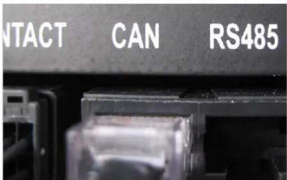
text_image
CONTACT CAN RS485Figure 5-1. System BMS LED
5.1.14 Communication Failure (System BMS ↔ Monitoring Software)
| Possible Problem | Solution |
| System BMS improperly initiated | - Check the communication from the SMPS Assembly data ports (TCP/IP or RS485) using the monitoring software and, if available, using an oscilloscope to check the waveform of the data signals.- Check the status of the LED inside the SMPS Assembly.Refer to Figure 5-1. System BMS LEDIf there is only steady red LED or no LED on, reset the System BMS by removing then reapplying the AC power to the SMPS Assembly (power-on reset). At least one or more red LED should be blinking inside the SMPS Assembly after power-on reset.- If the problem persists, refer to 5.1.19. BMS Power is Off. |
5.1.15 MCCB Failure (Minor Protection)
| Possible Problem | Solution |
| Defective Rack BMS | - Press the reset switch in the SMPS Assembly and see if it clears the protection.- Make sure that the MCCB handle is in the “trip” or “off” position.- Measure the current using monitoring software while the battery is idle.- If measured current is not 0A, the current sensing units may be malfunctioning.- Replace the Switchgear Assembly. |
| Defective MCCB | - Press the reset switch in the SMPS Assembly and see if it clears the protection.- Make sure that the MCCB handle is in the “trip” or “off” position.- Check the continuity between the “B-” terminal and the “P-” terminal.- If there is continuity between the two terminals, the MCCB is defective.- Replace the Switchgear Assembly. |
| Defective Auxiliary Unit | - Move the MCCB handle to the “on” position.- Use the monitoring software to check the status of the MCCB.- If the MCCB status is “off,”the MCCB auxiliary unit may be malfunctioning.- Replace the Switchgear Assembly. |
5.1.16 MCCB Sensor Failure (Minor Protection)
| Possible Problem | Solution |
| Defective Auxiliary Unit | - Press the trip button on the MCCB to trip it. Shift the MCCB handle to “off,” then to the “on” position.- Press the reset switch in the SMPS Assembly.- If the alarm is not cleared, the rack BMS may be defective. |
| Defective Rack BMS | - Press the reset switch in the SMPS Assembly and see if it clears the protection.- If the problem persists, replace the Switchgear Assembly. |
5.1.17 Current Sensing Error (Minor Protection)
| Possible Problem | Solution |
| Defective Internal Wiring | - Press the reset switch in the SMPS Assembly and see if it clears the protection.- Measure the current using monitoring software during charge or discharge.- If there is no reading, there may be a defect in the Rack BMS or the internal wirings in the Switchgear Assembly. Replace the Switchgear Assembly |
5.1.18 Fuse Failure (Minor Protection)
| Possible Problem | Solution |
| Fuse Blown | - When the MCCB is in the “on” position, check the continuity between the “B-” terminal and “P-” terminal.- If there is no continuity between the two terminals, the fuse is blown and must be replaced. Replace the Switchgear Assembly. |
| Defective Fuse Switch | - If the fuse is not blown, the switch above the fuse may be malfunctioning.- Replace the Switchgear Assembly. |
5.1.19 BMS Power is Off
| Possible Problem | Solution |
| Incorrect Cabling | - Check the cable connection to the terminal block on the front side of the SMPS Assembly.- Check the cable connection between the SMPS Assembly “DC OUT” and Switchgear Assembly “DC IN.” |
| AC Input Fuse Blown | - Remove the SMPS Assembly and remove the top cover.- Check the continuity of the AC input fuse holder.- If any fuse is blown, replace the SMPS Assembly. |
| Defective SMPS | - If all AC input connections are correctly installed and energized, but the BMS is not being powered, the SMPS Assembly may be defective. Replace the SMPS Assembly. |
5.1.20 MCCB Handle Cannot be Set to "On"
| Possible Problem | Solution |
| UPS Signaling the MCCB to Open | - Check the status of the UPS. Typical operation and end of discharge or due to an emergency power off will result in a trip signal to the battery MCCB's. The MCCB's will be prevented from closing until the UPS signal is removed. |
| System in Fault Status | - Check the indicator LED on the front side of the Switchgear Assembly- If the FAULT LED (red LED) is blinking, the major protection (fault) status is set.- Major protection must be cleared before setting the MCCB to “on.”- Press the reset button in SMPS Assembly Type A to clear the protection. |
| SMPS not Powered | - Check the AC input connection.- Check if the AC input is energized.- If all AC input connections are correctly installed and energized, SMPS Assembly may be defective. Replace the SMPS Assembly. |
| Defective Cable | - Check the cable connection to DC IN- If the cable is defective, replace the DC IN cable |
| Defective MCCB Unit | - Replace the Switchgear Assembly |
| Defective Rack BMS | - Check the indicator LED on the front side of the switchgear.- If the indicator LED is not operational or if all LED's are on, the Rack BMS may be defective.- Replace the Switchgear Assembly. |
5.2 Repair Procedures
Service personnel can resolve some problems by performing the following procedures without having to call Samsung SDI's customer service.
5.2.1 Module BMS Connection Check
 | CAUTION |
| Follow the instructions to protect the Module BMS against damage.Important: DO NOT deviate from the sequence of steps.The voltage of the connected system increases proportionally as battery modules are connected. Exercise extreme caution to prevent the terminals from touching anything other than their intended mounting points.Terminals and their connected wires have either positive or negative polarity (Positive: B+, P+; Negative: B-, P-). The polarity of a terminal or a wire connected to the terminal is on the front of each module and switchgear. To prevent a potentially dangerous short circuit, use extreme caution to prevent terminals and/or wires with opposite polarit from contacting each other.Do not permit either battery terminal to contact the rack frame because it is possible to contact a connection with the opposite polarity. |
Check the following points to make sure the Module BMS is connected correctly.
- Check the wire connection to the signal "IN" and "OUT" connectors. Make sure they are firmly inserted into the connector.

text_image
SAMSUNG SDI ESS IN OUTFigure 5-2: Signal "IN" and "OUT" Connectors
- Remove the front cover to check the voltage and temperature sensing connectors
5. Troubleshooting, Repair and Replacement
natural_image
Technical line drawing of an electrical enclosure or enclosure with multiple panels and mounting brackets (no text or symbols)Figure 5-3: Battery Module with Front Cover Removed
- Make sure that the voltage and temperature sensing wires are firmly inserted into the connector.

natural_image
Top-down schematic of a device layout with labeled components (no text or symbols)Figure 5-4: Voltage and Temperature Sensing Connectors
5.2.2 Switchgear Connection Check
Check the following points to make sure the switchgear is connected correctly.
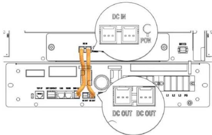
- Check the wire connection to the "DC IN" connectors. Both wires must be firmly inserted into the connectors.
text_image
DC IN POK MCC3 DC OUT DC OUTFigure 5-5: DC Power Cables from SMPS Assembly Type A to Switchgear

text_image
DC IN POM DC OUT DC OUTFigure 5-6: DC Power Cables from SMPS Assembly Type B to Switchgear
- Check the CAN connections to the Switchgear Assembly. For the rack with the SMPS Assembly Type A, one of the connections must be made to the SMPS Assembly. A termination resistor switch must be turned on in the rack that is farthest from the rack with SMPS Assembly Type A. Refer to Figure 5-9: Termination resistor setting.
5. Troubleshooting, Repair and Replacement

text_image
R0485 BMO CAMFigure 5-7: CAN Signal Cable Connection from SMPS Assembly to Switchgear
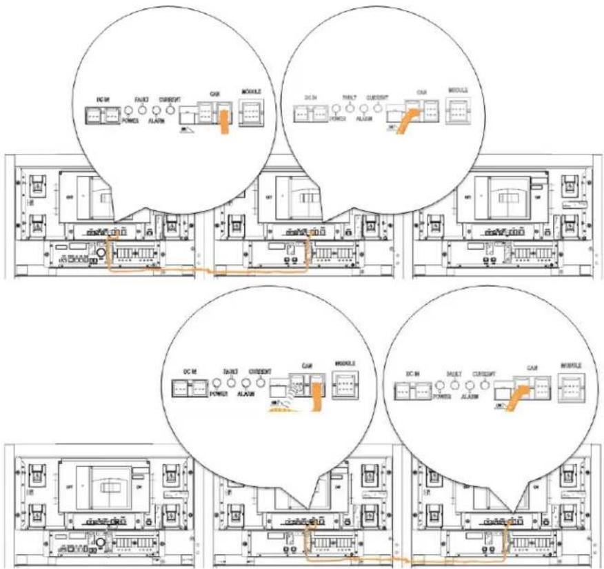
text_image
DC M FAINT CURRENT AIR MODULE DC IN TAINT CURRENT AIR MODULE DC M FAINT CURRENT AIR MODULE DC IN TAINT CURRENT AIR MODULEFigure 5-8: Signal Cabling Examples of Left Alignment of Switchgears
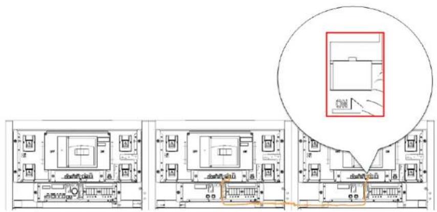
text_image
Architectural floor plan with room layouts and a highlighted section showing a room with 'ON' labelFigure 5-9: Termination resistor setting
5.2.3 SMPS Assembly Connection Check
- Check the wire connection to the "DC OUT" connectors. Both wires must be firmly inserted into the connectors.
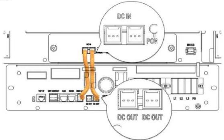
text_image
DC IN POK MOSB DC OUT DC OUTFigure 5-10: DC Power Cables from SMPS Assembly Type A to Switchgear
5. Troubleshooting, Repair and Replacement

text_image
DC IN POWER AC DC OUT DC OUTFigure 5-11: DC Power Cables from SMPS Assembly Type B to Switchgear
- Check the CAN connections to the Switchgear Assembly.

text_image
RS485 BMS CAM RESET CAM MODFigure 5-12: CAN Signal Cable Connection from SMPS Assembly to Switchgear Assembly
- Check the dry contact connector.
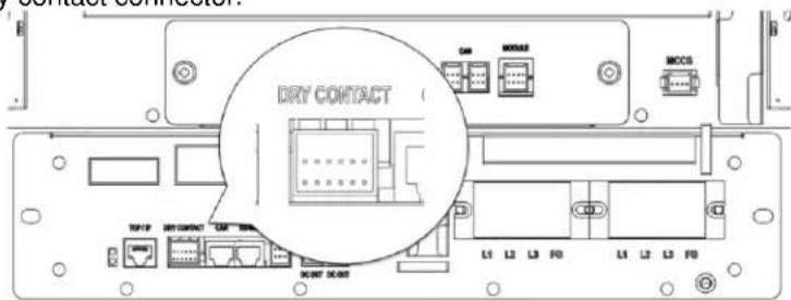
text_image
DRY CONTACT L1 L2 L3 F0 L1 L2 L3 F0Figure 5-13: Dry Contact Cable Connection to SMPS Assembly
WARNING
Before checking the AC input terminal connections, make sure they are not energized.
- Check the AC input terminal. Remove the protective cover.
text_image
Technical diagram of an electronic device with labeled components and directional arrows indicating motion or movement.Figure 5-14: AC Input Terminals
- Check each AC input in the SMPS Assembly.
text_image
Technical diagram of a network device rear panel with labeled ports, connectors, and cable routingFigure 5-15: AC Input Terminals with Cables Attached
- Reattach the protective covers to the AC input terminals.
natural_image
Technical line drawing of an electrical enclosure with internal components and wiring (no text or symbols)Figure 5-16: AC Input Terminals Protective Covers
5.2.4 Busbar Connection Check

Verify for zero energy state or isolation between racks (strings)!
Make sure that the UPS interface is locked out and tagged out!
 | CAUTION |
| Follow the instructions exactly to protect the module BMS from damage.Important: DO NOT deviate from the sequence of the steps below.The voltage of the connected system increases proportionally as battery modules are connected. Exercise extreme caution to prevent the terminals from touching anything except their intended mounting points.Terminals and their connected wires have either positive or negative polarity (Positive: B+, P+; Negative: B-, P-). The polarity of a terminal or a wire connected to the terminal is on the front of each module and switchgear. Exercise extreme caution to prevent terminals and/or wires with opposite polarity from contacting each other.Do not permit either battery terminal to contact the rack frame because it is possible to contact a connection with the opposite polarity. |
 | WARNING |
| ▪ Covers protect the power terminals on Battery Modules and Switchgear Assemblies to guard against a short circuit. Power terminal covers must be removed before connecting a power busbar. The covers must be reattached immediately. |
Verify that the bolts connecting the busbars are properly torqued..
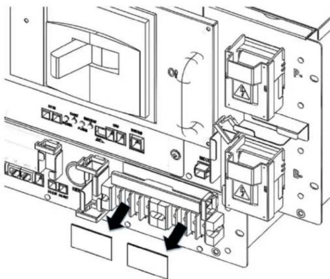
- Remove the Battery Module front covers and Switchgear B+, B-, P+, P- covers.
natural_image
Technical line drawing of a multi-level industrial or server rack system, showing internal components and structural layout (no text or labels)Figure 5-17: Remove the front covers
- Check the torque settings of the bolts on the busbar.
NOTICE
- Connect the power busbar to battery module terminals with an M8 screw.
- The fastening torque should be 8.16–11.94 Nm/80 (117 kgf cm).
- Use an insulated extension torque wrench with a 13 mm socket.

NOTICE
- Connect the power busbar to Switchgear terminals with an M12 screw.
- The fastening torque should be 30 Nm (300 kgf cm).
-
Use an insulated extension torque wrench with a 19 mm socket.
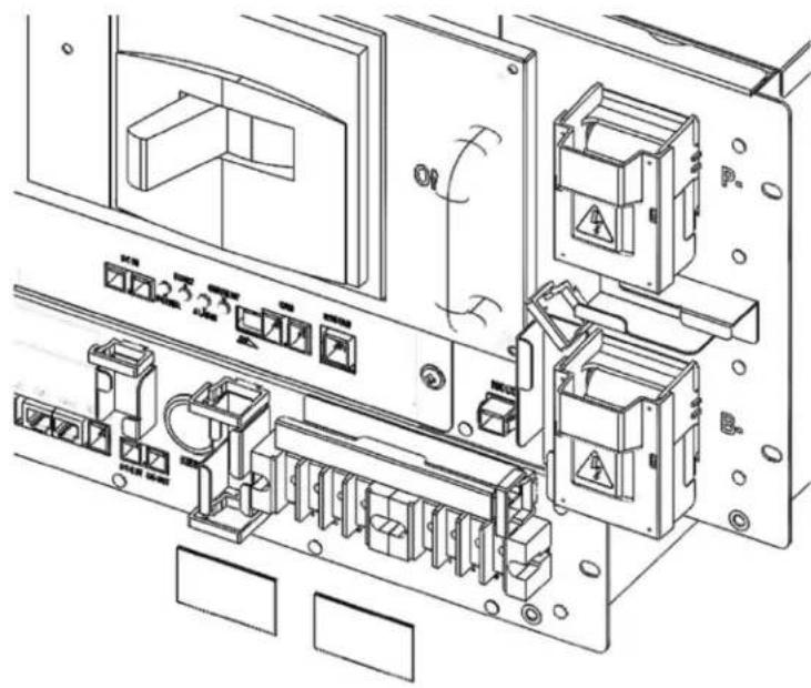
-
Reattach the Battery Module front covers and Switchgear B+, B-, P+, P- covers.
natural_image
Technical line drawing of an electrical control cabinet with internal components (no text or symbols)Figure 5-18: Reattach the Front Covers
5.2.5 Cell Voltage Balancing
When the battery system is idle – neither charging nor discharging– it will balance the cell voltage if the following conditions are present:
• Minimum cell voltage is above 3.0V.
- Discrepancy between the cell voltage is above the 20mV range.
Cell voltage balancing runs automatically whenever the battery system is idle (neither charging nor discharging).
5.2.6 System Reset
To reset the battery system after a major protection fault, press the "reset button" on the front of the SMPS Assembly Type A. This will reset all protection conditions and return the system to normal status.

text_image
NOTICE • Make sure all protection conditions have been cleared before pressing the reset button. • Refer to 5.1 Troubleshooting for guides on clearing protection conditions.Figure 5-19: Pressing the Reset Button
5.2.7 MCCB Handle Control
 | CAUTION |
| Terminals and their connected wires have either positive or negative polarity (Positive: B+, P+; Negative: B-, P-). The polarity of a terminal or a wire connected to the terminal is on the front of each module and Switchgear. Exercise extreme caution to prevent terminals and/or wires with opposite polarity from contacting each other.Do not permit either battery terminal to contact the rack frame because it is possible to contact a connection with the opposite polarity. | |
 | WARNING |
| Covers protect the power terminals on Battery Modules and Switchgear Assemblies to guard against a short circuit.When handling the MCCB, make sure the covers are installed properly. | |
- Make sure all major protection is cleared by checking the indicator LED in front of the switchgear. Before handling the MCCB, verify that the indicator LED is in normal status.
| LED Status | Battery Status | Remarks |
| POWER LED Steady | Normal Status | MCCB Off |
- If the MCCB handle is in the "TRIP" position, move the handle to the left "OFF" position. If the MCCB handle is already in the "OFF" position, proceed to the next step.
5. Troubleshooting, Repair and Replacement
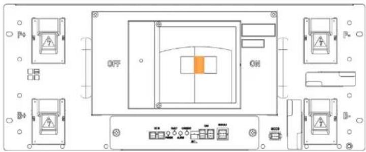
text_image
OFF ONFigure 5-20: MCCB Handle in Trip Position
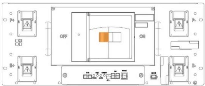
text_image
OFF ONFigure 5-21: MCCB Handle in Off Position
- Press the handle to the right "ON" position.
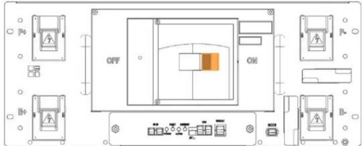
text_image
OFF ONFigure 5-22: MCCB Handle in On Position
- Check the switchgear indicator LED. Make sure that the indicator LED is in normal status and that the MCCB is on.
| LED Status | Battery Status | Remarks |
 POWER POWER FLashing POWER POWER FLashing | Normal Status | MCCB On |
5.3 Replacement Procedures
 | WARNING |
| Arc Flash and Shock HazardAppropriate tools are required while working on this energized equipment. | |
 | WARNING |
| Sharp EdgesWear protective gear, including gloves, when working within the battery system enclosures.Sharp edges can exist and may cause severe injury. | |
 | WARNING |
| Pinch PointMultiple pinch-points are present in most system components. Be aware that there is a serious risk of injury while working around and in equipment enclosures. These pinch points can cause severe bodily injury. | |
 | CAUTION |
| Heavy objectCan cause muscle strain or back injury.Use lifting aids and proper lifting techniques when moving trays, batteries and other heavy objects. | |

Verify with a voltmeter that no power is present on the system. Use lock out/tag out procedures to secure the UPS and batteries.
This section will explain the procedures for disassembly and installation of user-replaceable components. Follow the safety instructions when replacing Battery Modules, Rack Fuse, Switchgear Assembly, and SMPS Assembly. Refer to the installation manual for more details.
5.3.1 Wire Harness Replacement
| NOTICE |
| ·Use only the proper signal cables. These are specified by the part names in the parts list table of the installation manual. |
| WARNING |
| Rack BMS / Module BMS Damage Do not insert both ends of the signal cable WIRE ASSY MODULE TO MODULE #1 or WIRE ASSY MODULE TO MODULE #2 into the same Battery Module. |
5.3.1.1 Switchgear Assembly to Module Wire Harness Replacement
- Remove the signal cable "WIRE ASSY RACK TO MODULE SHIELDING" between the Switchgear Assembly "MODULE" connector and Module #1 "OUT" connector. Press the tab above each end of the connectors and pull the wires out gently.

text_image
SAMSUNG 3X ESSFigure 5-23: Remove Switchgear to Module #1 OUT Signal Cable
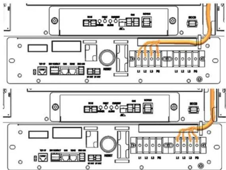
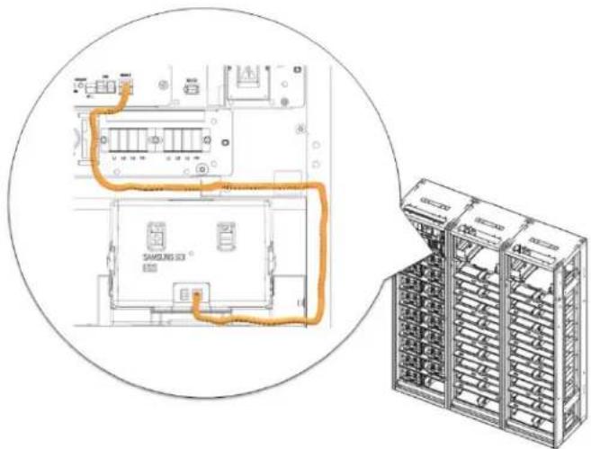
- Install the replacement wire harness signal cable "WIRE ASSY RACK TO MODULE SHIELDING" between the Switchgear Assembly "MODULE" connector and Battery Module #1 "OUT" connector. Pass the cable through the opening above Module #1.
text_image
Technical diagram showing a schematic of an electrical module connected to a server rack unit, with orange wiring indicating connections.Figure 5-24: Install Signal Cable Between the Switchgear and Battery Module #1 OUT

text_image
Technical diagram of an electrical cabinet with labeled internal components and a blue arrow pointing to a component.Figure 5-25: Opening for Cable Installation
5.3.1.2 Module to Module Wire Harness Replacement
- Remove the signal cable "WIRE ASSY MODULE TO MODULE."
5. Troubleshooting, Repair and Replacement
natural_image
Technical line drawing of a server rack with an orange cable inserted, showing internal components and wiring (no text or symbols)Figure 5-26: Remove Module to Module Signal Cable
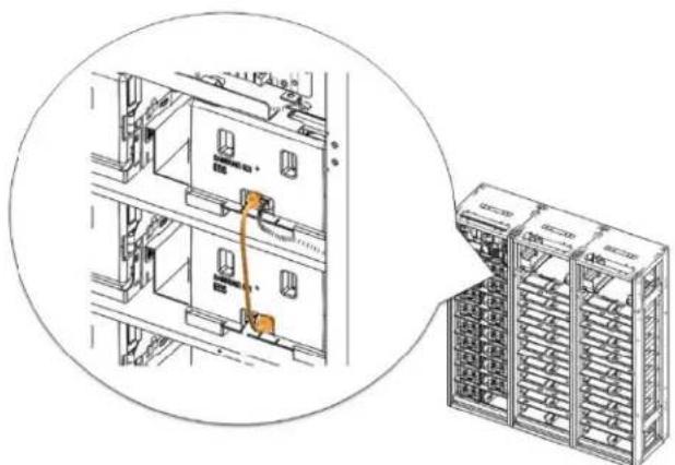
- Install the replacement signal cable "WIRE ASSY MODULE TO MODULE."

text_image
Technical diagram showing a device rack with labeled components and an inset view of its internal structure.Figure 5-27: Install Module to Module Signal Cable
5.3.1.3 Switchgear to Switchgear CAN Wire Harness Replacement
- Remove the CAN wire harness between Switchgear Assemblies.
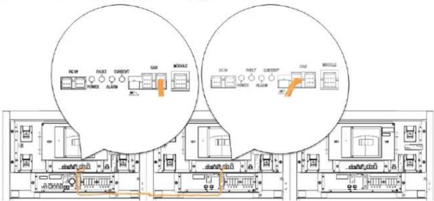
text_image
DC 5V FAU32 CURRENT CAR MODULE DC 5M FAULT CURRENT CAR MODULE5. Troubleshooting, Repair and Replacement

text_image
DC M SUNT CURRENT CAM MOBILE DC M SUNT CURRENT CAM MOBILEFigure 5-28: CAN Wire Harness Between Switchgear Assemblies
- Install the replacement CAN wire harness between switchgears
5.3.1.4 Switchgear to SMPS Assembly CAN Wire Harness Replacement
- Remove the CAN wire harness between the Switchgear and SMPS Assembly.

Figure 5-29: CAN Cable Connection from SMPS Assembly to Switchgear
- Install the replacement CAN wire harness between the Switchgear and SMPS Assembly.
5.3.1.5 Switchgear to SMPS Assembly DC Power Wire Harness Replacement
1. Turn the MCCB off.
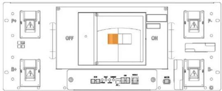
text_image
OFF ONFigure 5-30: MCCB Handle in "OFF" position
2. Remove the DC power wire harness.
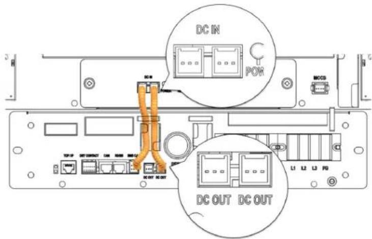
text_image
DC IN POR MCCS DC OUT DC OUTFigure 5-31: DC Power Cables from SMPS Assembly Type A to Switchgear

text_image
DC IN POWER MCCB DC OUT DC OUT L1 L2 L3 F0Figure 5-32: DC Power Cables from SMPS Assembly Type B to Switchgear
-
Troubleshooting, Repair and Replacement
-
Install the replacement DC power wire harness
-
Check the indicator LED and make sure it is in normal status.
-
Turn the MCCB on.
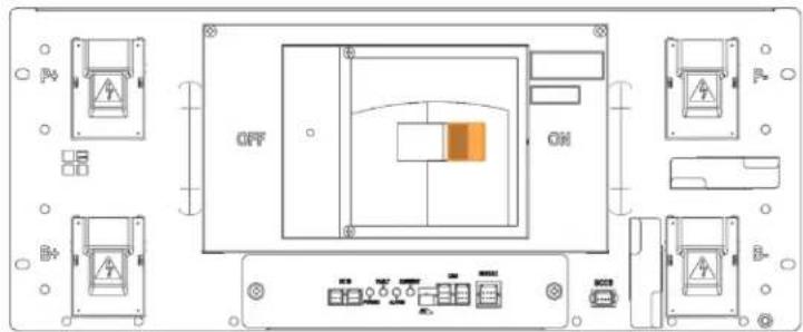
text_image
OFF ONFigure 5-33: MCCB Handle in "ON" Position
5.3.2 Battery Module Replacement

CAUTION
- Follow the instructions exactly to protect the Module BMS and Battery Module from damage.
- DO NOT deviate from the sequence of steps below.
- The voltage of the connected system increases proportionally as battery modules are connected. Exercise extreme caution to prevent the terminals from touching anything other than their intended mounting points.
- Terminals and their connected wires have either positive or negative polarity (Positive: B+, P+; Negative: B-, P-). The polarity of a terminal or a wire connected to the terminal is on the front of each module and switchgear. Exercise extreme caution to prevent terminals and/or wires with opposite polarity from contacting each other.
- Do not permit either battery terminal to contact the rack frame because it is possible to contact a connection with the opposite polarity.

NOTICE
- Connect the power busbar to the Battery Module Terminals with an M8 screw. Use an insulated extension torque wrench with a 13 mm socket.
- The fastening torque should be 8.16–11.94 Nm (80–117 kgf cm).

NOTICE
- Connect the power busbar to the Switchgear terminals with an M12 bolt. Use an insulated extension torque wrench with a 19 mm socket
- The fastening torque should be 30 N·m (300 kgf·cm).
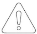
NOTICE
-
When charging or discharging the battery module, the following settings must be followed to prevent damaging the battery module.
■ Maximum charge voltage : 33.6V
■ Minimum discharge voltage : 24V
■ Maximum charge current : 22.3A
■ Maximum discharge current : 67A -
Identify the defective Battery Module's type. It must be replaced with an identical Battery Module. Type A's positive (+) terminal is on the right side when viewed from the front; Type B's positive (+) terminal is on the left.

text_image
SAMSUNG SDI ESSFigure 5-34: Battery Module Type A

- Turn the MCCB off by pushing the MCCB handle to the "OFF" position.
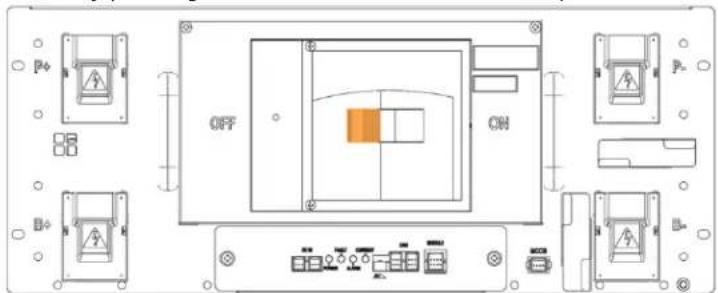
text_image
OFF ONFigure 5-36: MCCB Handle in "OFF" Position
-
Troubleshooting, Repair and Replacement
-
Turn off the AC input to the SMPS Assembly.
- Remove front covers from all Battery Modules.

natural_image
Technical line drawing of an electrical control panel assembly (no text or symbols visible)Figure 5-37: Remove Battery Module Front Covers
- Use a multimeter to measure the voltage of each Battery Module except the defective Battery Module. Record the measurements for reference.

text_image
Diagram showing a multimeter connected to an electrical panel with red and black wires indicating connections or wiring paths.Figure 5-38: Measuring Each Battery Module's Voltage
- Reattach the front covers to all Battery Modules.
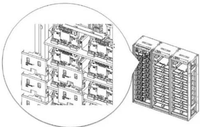
natural_image
Technical line drawing of a multi-level industrial control room with internal components and a separate rack-mounted unit (no text or symbols visible)Figure 5-39: Assemble Battery Module Front Covers
- Charge or discharge the replacement Battery Module to match the average voltage of the other modules.
If the replacement Battery Module's voltage is higher than the other battery modules, use a controllable load to discharge the battery module to match the voltage to within 300mV of the other Battery Modules' average voltage.
If the replacement Battery Module's voltage is lower than the other Battery Modules, use a controllable DC power supply to charge the Battery Module to match the other Battery Modules' average voltage to within 300mV.
When using a DC power supply to charge the battery module directly, use a switch or a circuit breaker between the battery module's terminal and the DC power supply's terminal. Refer to the diagram below.
text_image
DC Power Supply + - SAMSUNG SOI ESSFigure 5-40: DC Power Supply and Battery Module Connection
Before turning the switch or the circuit breaker on, DC power supply's output voltage must match the Battery Module's voltage to prevent inrush current from the battery.
Set the DC power supply's output voltage to the Battery Module's voltage.
Set the output current to 0A.
Turn the DC power supply's output on to pre-charge the capacitors within the power supply.
Turn the switch or circuit breaker on
Raise the output voltage of the DC power supply to the charging voltage.
Set the output current to 22.3A or less.
When the output of the DC power supply reaches the set charging voltage and charging current is decreased to less than 1.34A, stop charging the battery module by disconnecting the switch or circuit breaker.
Turn the DC power supply's output off.
Disconnect the charged battery module
- Disconnect the control cables from the defective Battery Module.
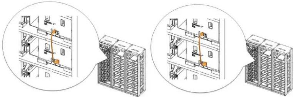
natural_image
Technical line drawing showing three views of a server rack with orange connectors, no text or symbols presentFigure 5-41: Battery Module Signal Cables
- Remove the front covers from the defective Battery Module and adjacent Battery Modules.

natural_image
Technical line drawing of a multi-level industrial control room with internal equipment and a separate rack unit (no text or symbols visible)Figure 5-42: Battery Module Front Covers
- Unbolt the positive and negative busbars from the terminals on the defective Battery Module and the adjacent battery modules.
5. Troubleshooting, Repair and Replacement
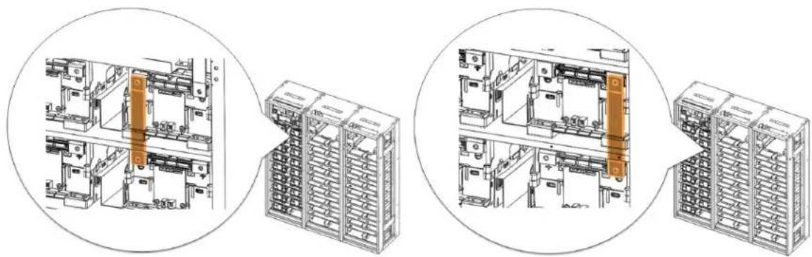
natural_image
Technical line drawings of server rack and storage unit layout (no text or symbols)Figure 5-43: Busbars on Positive and Negative Terminals
- Remove the two busbars.
- Using a rod (a long screwdriver of at least 254mm [10 in.] long may be used), pivot the guide in the Rack Frame to separate the hooks on the Battery Module from the matching hole in the rack frame.
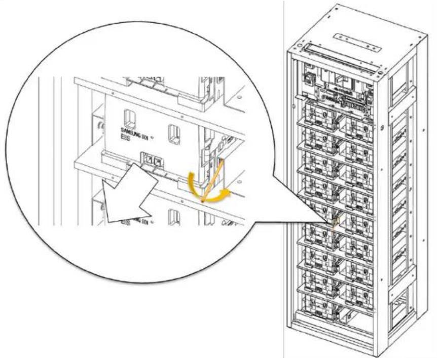
text_image
SAMSUNG 301 EBSFigure 5-44: Pivoting the Guide and Pulling the Battery Module Out
- Pull out the Battery Module while pivoting the guide and remove the Battery Module from the rack frame.
- Insert the replacement Battery Module.
5. Troubleshooting, Repair and Replacement

natural_image
Isometric line drawing of a multi-level storage or warehouse rack system with no visible text or symbolsFigure 5-45: Inserting the Replacement Battery Module
- Remove the front cover from the replacement Battery Module and from adjacent Battery Module.

natural_image
Technical line drawing of a multi-level industrial control room with internal compartments and a separate rack unit (no text or symbols)Figure 5-46: Removing the Front Covers
- Install the busbars.
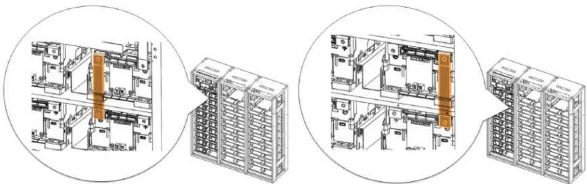
natural_image
Technical line drawings of industrial electrical equipment layout, showing internal components and assembly steps (no text or labels)Figure 5-47: Busbars
- Reattach the front cover to the Battery Module.
5. Troubleshooting, Repair and Replacement

natural_image
Technical line drawing of a multi-level industrial control room with internal components and a separate rack-mounted unit (no text or symbols visible)Figure 5-48: Reattaching the Front Cover to the Battery Module
- Reconnect the signal cables.

natural_image
Technical line drawing showing three views of a server rack with orange connectors, no text or symbols present.Figure 5-49: Connecting the Signal Cables
- Turn on the AC input to the SMPS Assembly.
- Check the indicator LED and make sure it is in normal status.
- Turn the MCCB handle to the "ON" position.
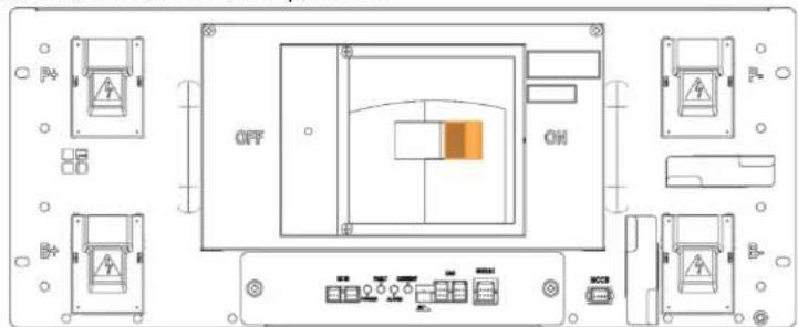
text_image
OFF ONFigure 5-50: MCCB Handle in "ON" Position
5.3.3 Rack Fuse Replacement
 | CAUTION |
| Follow the instructions exactly to protect the Module BMS and Battery Module from damage.DO NOT deviate from the sequence of the steps below.The voltage of the connected system increases proportionally as battery modules are connected. Exercise extreme caution to prevent the terminals from touching anything other than their intended mounting points.Exercise extreme caution to prevent terminals and wires from contacting a wire or terminal with the opposite polarity.Do not permit either battery terminal to contact the rack frame because it is possible to contact a connection with the opposite polarity. |
 | NOTICE |
| The Rack Fuse Busbar Assembly is assembled at the installation site using M12 x 16L screws.The fastening torque should be 30 Nm (300 kgf cm). |
- Turn the MCCB off. If multiple strings are installed in parallel, turn the MCCB off for all racks.

text_image
OFF ONFigure 5-51: MCCB Handle in "OFF" Position
- Turn off the AC input to the SMPS Assembly.
- Remove the rack fuse cover.
5. Troubleshooting, Repair and Replacement
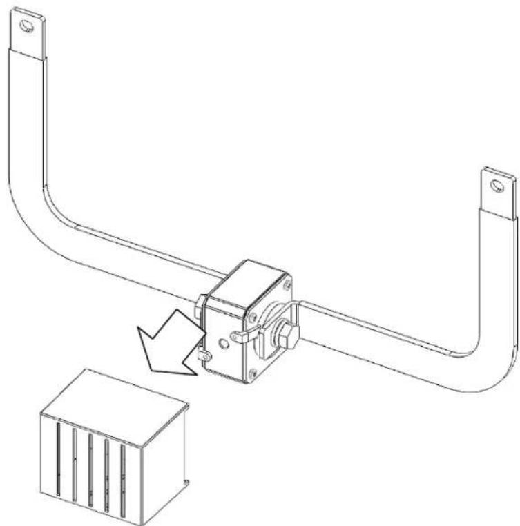
natural_image
Technical line drawing of a mechanical assembly with a bracket and housing, showing a directional arrow indicating motion (no text or symbols present)Figure 5-52: Removing Rack Fuse Cover
- Remove front covers from the Battery Modules adjacent to the rack fuse.

natural_image
Technical line drawing of a multi-level industrial control room with internal components and a separate rack unit (no text or symbols visible)Figure 5-53: Remove the Battery Module Front Covers
- Remove the bolts from the Battery Module terminals that are connected to the rack fuse.
5. Troubleshooting, Repair and Replacement

natural_image
Technical line drawing of a dual-chamber electronic device with no visible text or symbolsFigure 5-54: Remove the Bolts from Battery Module Terminals
- Remove the rack fuse assembly.
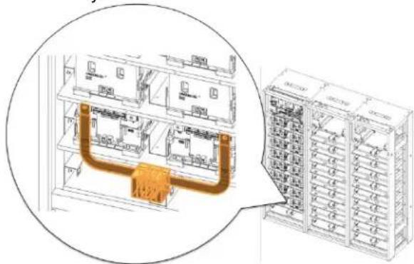
text_image
Technical diagram showing internal components of an electrical cabinet with labeled parts and a magnified view highlighting the main structure.Figure 5-55: Remove the Rack Fuse Assembly
- Remove the busbars and bolts attached to the rack fuse and reattach the busbars and bolts to the replacement rack fuse.
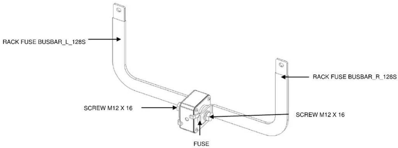
text_image
RACK FUSE BUSBAR_L_128S SCREW M12 X 16 FUSE RACK FUSE BUSBAR_R_128S SCREW M12 X 16Figure 5-56: Rack Fuse Busbar Assembly
- Attach the replacement rack fuse with busbars attached.

natural_image
Technical line drawing of an electrical enclosure with internal components and wiring, shown in a circular inset (no text or symbols)Figure 5-57: Attach the Replacement Rack Fuse Assembly
- Assemble the bolts for the Battery Module terminals.
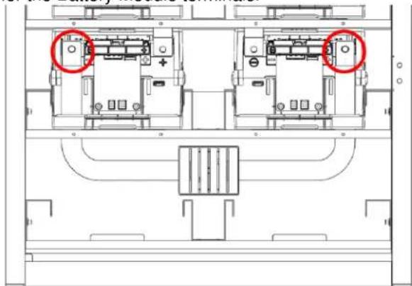
natural_image
Architectural floor plan showing two internal compartments with red circles highlighting specific areas (no text or labels)Figure 5-58: Bolts for the Battery Module Terminals
- Reattach the front covers to the Battery Modules.
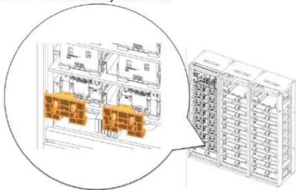
text_image
Technical diagram showing internal layout of electrical equipment with labeled components and a magnified view of the main panel.Figure 5-59: Battery Module Front Cover
- Reattach the rack fuse cover.
5. Troubleshooting, Repair and Replacement

natural_image
Technical line drawing of a mechanical component with two curved arms and a small inset box (no text or symbols)Figure 5-60: Rack Fuse Cover
- Turn on the AC input to the SMPS Assembly.
- Check the Switchgear indicator LED and make sure it is in normal status.
- Turn the MCCB handle to the "ON" position.

text_image
OFF ONFigure 5-61: MCCB Handle in "ON" Position
5.3.4 Switchgear Replacement
- Turn the MCCB off. If multiple strings are installed in parallel, turn the MCCB off for all racks.
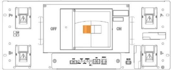
text_image
OFF ONFigure 5-62: MCCB Handle in "OFF" Position
- Remove the DC input and communication wires from the Battery Module, the adjacent rack and the SMPS Assembly.
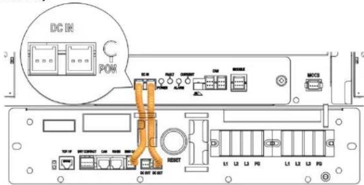
text_image
DC IN POM DC IN POWER ALUM CURRENT CM MOBILE MCCS TCP/IP NET CONTACT CAM RUBB MEMC RESET DC OUT DC OUT L1 L2 L3 F0 L1 L2 L3 F0Figure 5-63: DC IN Cable
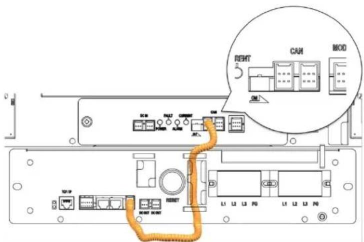
text_image
RIGHT CAN MOD DCB PUL27 CORIPT CM POWER ALAB INT DCB PUL27 CORIPT CM POWER ALAB INT DCB PUL27 CORIPT INT DCB PUL27 CORIPT INT DCB PUL27 CORIPT INT DCB PUL27 CORIPTFigure 5-64: CAN Cable to SMPS Assembly
5. Troubleshooting, Repair and Replacement
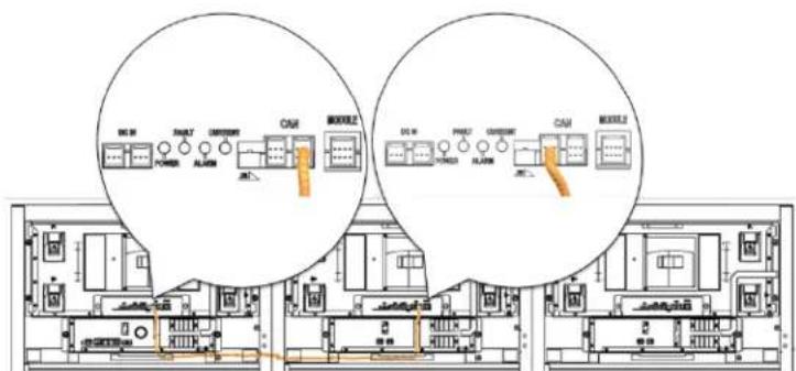
text_image
DC 31 POWER RUNUT CANCE CAM MODEL2 DO 8 PROD CURRENT CAM MODEL2Figure 5-65: CAN Cable to Adjacent Rack
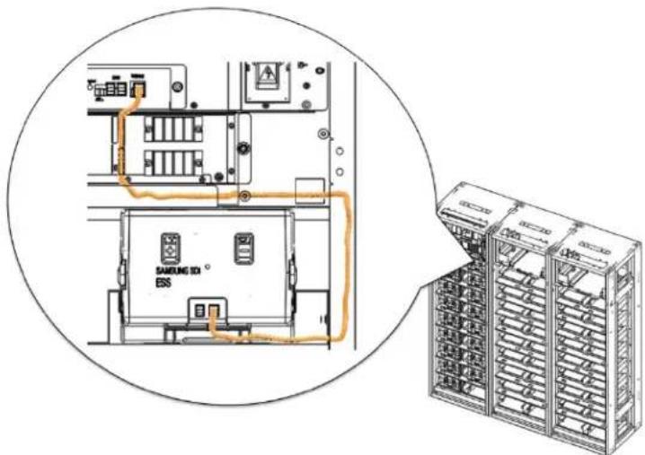
text_image
SAMSUNG ID ESFigure 5-66: Module Signal Cable
- Remove the front cover from the Battery Module on the ninth shelf.
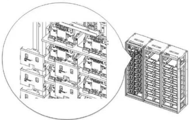
natural_image
Technical line drawing of a multi-level industrial or server rack system, showing internal components and structural layout (no text or labels)Figure 5-67: Battery Module Front Covers
- Remove the bolts from B+ on Battery Module #16, and from B- on Battery Module #1.
5. Troubleshooting, Repair and Replacement

natural_image
Technical line drawings of industrial equipment and storage units, showing internal components and assembly (no text or symbols)Figure 5-68: Bolts on Battery Modules
- Remove terminal covers from the battery terminals.

text_image
Technical diagram of an electrical switchgear assembly with labeled components and directional arrows indicating movement or operation.Figure 5-69: Switchgear Assembly Terminal Covers
- Hold the busbar on its insulated portion and remove the bolts from the terminals for B+, B-terminals.
- Remove the busbars.
5. Troubleshooting, Repair and Replacement
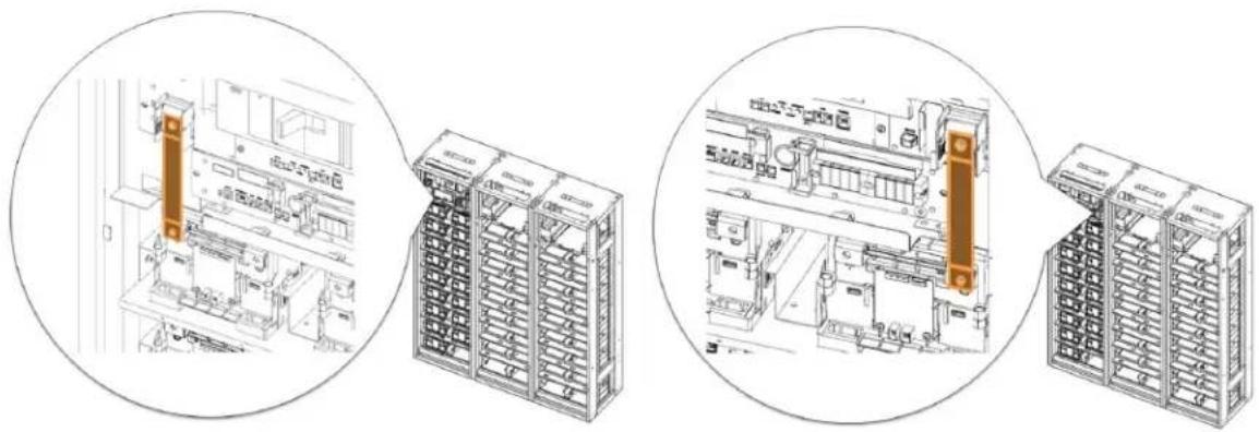
natural_image
Technical line drawings of industrial equipment and storage racks, showing internal components and assembly (no text or symbols)Figure 5-70: Busbars
- Remove the connections to P+, P- terminals. Make sure there is adequate clearance in front of the Switchgear Assembly for its easy removal.
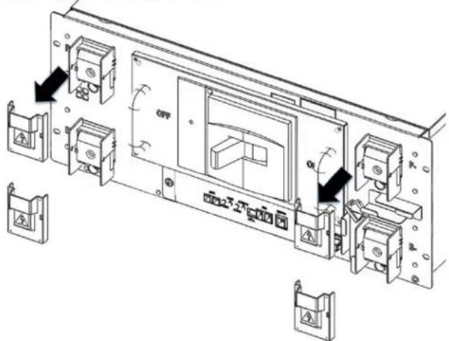
text_image
Technical diagram of an electronic device with labeled components and directional arrows indicating movement or operation.Figure 5-71: P+, P- Terminals
- Remove screws from the Switchgear Assembly and its ground cable.
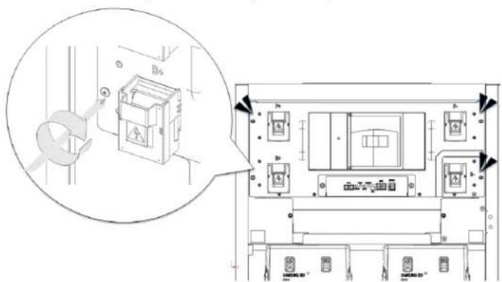
text_image
Technical diagram showing a device with labeled components and an inset view of the internal structure.Figure 5-72: Screws on Switchgear Assembly
5. Troubleshooting, Repair and Replacement
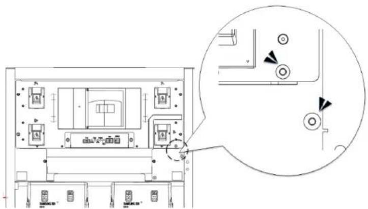
text_image
Technical diagram of an electrical enclosure with labeled components and a magnified detail view showing internal wiring connections.Figure 5-73: Screws on Switchgear Assembly Grounding Cable
- Remove the Switchgear and insert its replacement.
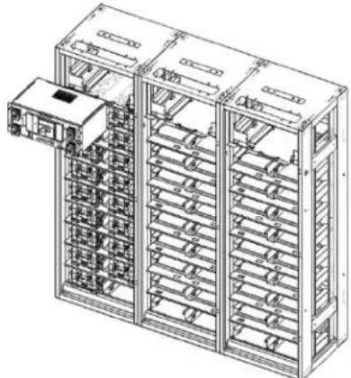
natural_image
Technical line drawing of a multi-level rack-mounted server unit with internal compartments and a single door (no text or symbols)Figure 5-74: Replacing Switchgear
- Insert and tighten the screws on the Switchgear and its grounding cable.

text_image
Technical diagram showing a device with labeled components and an inset view of its internal structure, including a magnified view of the component.Figure 5-75: Screws on Switchgear
5. Troubleshooting, Repair and Replacement

text_image
Technical diagram of a device rear panel with labeled components and an inset view showing internal wiring connections.Figure 5-76: Screws on Switchgear Grounding Cable
- Reattach the busbars and reinstall the bolts for B+ for Battery Module #16, and B- for Battery Module #1.
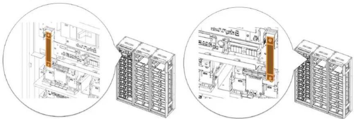
natural_image
Technical line drawings of industrial equipment components, showing front and side views with no visible text or symbols.Figure 5-77: Busbars
- Reinstall the bolts for B+ and B- terminals.
- Reinstall the bolts for P+ and P- terminals.
- Reattach the terminal covers.
5. Troubleshooting, Repair and Replacement
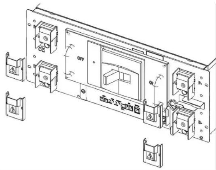
text_image
Technical diagram of an electronic device with labeled components including OFF, ON, and mounting bracketsFigure 5-78: B+, B-, P+, P- Terminal Connections and Terminal Covers
- Reattach the signal cables to the Battery Module, adjacent rack, SMPS Assembly, and DC IN cable.
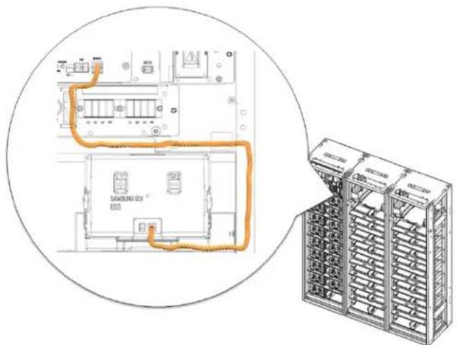
text_image
SAMSUNG BOX R205Figure 5-79: Switchgear to Module Signal Cable
5. Troubleshooting, Repair and Replacement

text_image
RAMS BMS CAMFigure 5-80: Switchgear to SMPS Assembly CAN Signal Cable
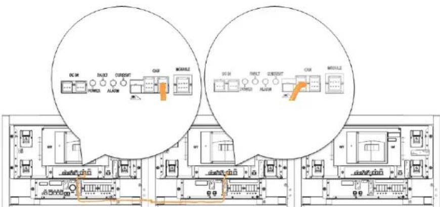
text_image
DC M FANJ CURRENT CM MODULE DC M FANJ CURRENT CM MODULEFigure 5-81: Adjacent Rack CAN Signal Cable

text_image
DC IN POM DC OUT DC OUTFigure 5-82: DC Power Cables from SMPS Assembly Type A to Switchgear
5. Troubleshooting, Repair and Replacement
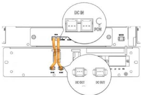
text_image
DC IN POW DC OUT DC OUTFigure 5-83: DC Power Cables from SMPS Assembly Type B to Switchgear
- Check the indicator LED and make sure it is in normal status.
- Turn the MCCB handle to "ON" position.

text_image
OFF ONFigure 5-84: MCCB Handle in "ON" Position
- The Rack BMS in the replacement Switchgear must be configured according to the rack configuration. Refer to the "Installation Manual" for details.
5.3.5 SMPS Assembly Replacement
1. Turn off the MCCB.

text_image
OFF ONFigure 5-85: MCCB Handle in "OFF" Position
2. Turn off the AC input to the SMPS Assembly.
 | WARNING |
| Before working on the AC input terminal connections, use a voltmeter to verify that they are not energized. |
3. Remove the protective covers from the AC input terminals.
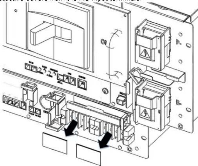
text_image
Technical diagram of an electronic device with labeled components and directional arrows indicating motion or assembly.Figure 5-86: AC Input Terminals
- Remove the AC input cables. Make sure the AC cables are not energized.
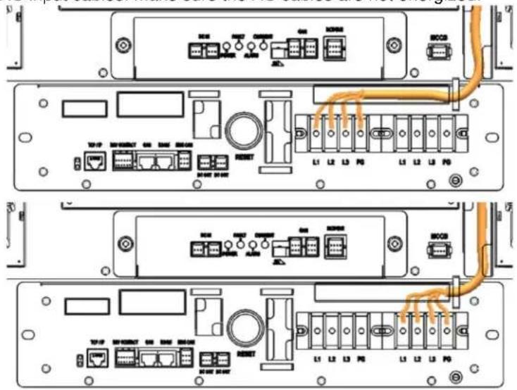
text_image
Technical diagram of server rack-mounted network ports with labeled connectors and portsFigure 5-87: Cables to the AC Input Terminals
- Remove the DC OUT connection.
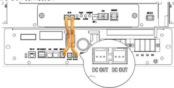
text_image
DC IN POWER ALARM CURRENT ON MOSS MCCS TCP/IP NET CORNUT CAN RANGE BLOGIC DC OUT DC OUT L1 L2 L3 F0Figure 5-88: DC OUT Connection
- Remove the BMS CAN connection.
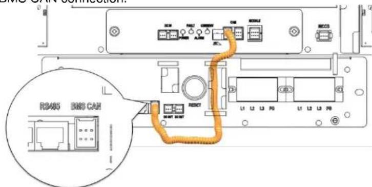
text_image
RS405 EMS CANFigure 5-89: BMS CAN Connection
5. Troubleshooting, Repair and Replacement
7. Remove the TCP/IP connection.

text_image
TCP/IP TCP/IP USB/USBFigure 5-90: TCP/IP Connection
8. Remove the dry contact connection.
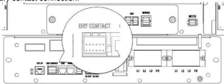
text_image
DRY CONTACT TYP1P TYP2M TYP3M MOCS L1 L2 L3 F0 L1 L2 L3 F0Figure 5-91: Dry Contact Connection
9. Unscrew the SMPS Assembly from the rack frame.

text_image
Technical diagram showing electrical panel layout with labeled components and a magnified detail view highlighting safety warnings.Figure 5-92: Unscrew SMPS Assembly
5. Troubleshooting, Repair and Replacement
- Detach the grounding cable from the rack frame.

text_image
Technical diagram of an electronic device layout with labeled components and a magnified inset showing circular components.Figure 5-93: Unscrew SMPS Assembly Grounding Cable
- Remove the SMPS Assembly.

natural_image
Technical line drawing of a multi-level server rack cabinet with internal compartments and mounting brackets (no text or labels)Figure 5-94: Remove the SMPS Assembly
-
Insert the replacement SMPS Assembly into the rack frame on the shelf designated for it.
-
Troubleshooting, Repair and Replacement
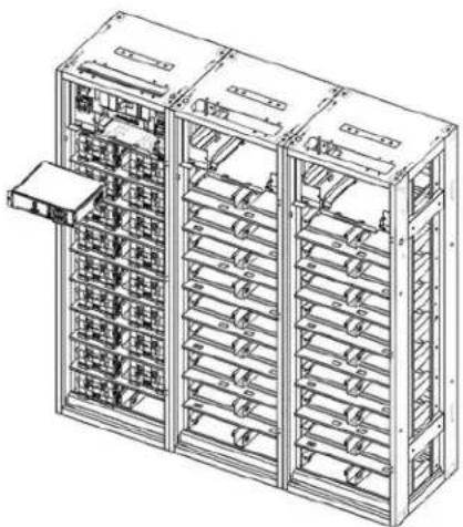
natural_image
Technical line drawing of a multi-level rack-mounted server cabinet with internal compartments and mounting brackets (no text or labels)Figure 5-95: Insert the SMPS Assembly
- Attach the SMPS Assembly to the rack frame using screws and torque them to 5.1–6.1 Nm (50–60 kgf cm).

text_image
Technical diagram showing electrical panel layout with labeled components and a magnified view of the main panel.Figure 5-96: Screw on the SMPS Assembly
- Connect the ground cable to the SMPS Assembly.

| NOTICE |
| Connect a ground cable between the SMPS Assembly and the Rack Frame using SCREW M5 x 10L. Torque the screw to 5.1–6.1 Nm (50–60 kgf cm).Double-check that the torque setting is correct. |
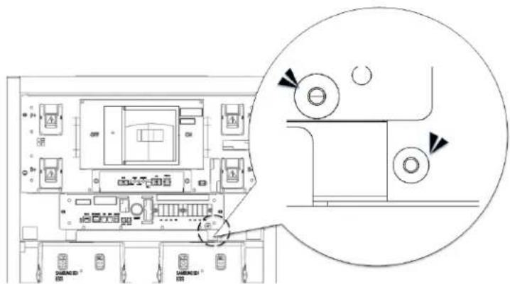
text_image
Technical diagram of an electronic device layout with labeled components and a magnified inset showing circular detail views.Figure 5-97: Screw on the SMPS Assembly Grounding Cable
- Connect the Switchgear DC power cables.

text_image
DC IN POK DC OUT DC OUTFigure 5-98: DC Power Cables from SMPS Assembly Type A to Switchgear
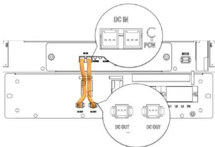
text_image
DC IN POK DC OUT DC OUTFigure 5-99: DC Power Cables from SMPS Assembly Type B to Switchgear
- Connect the signal cable from the SMPS Assembly to the Switchgear "WIRE ASSY RACK TO SYSTEM."
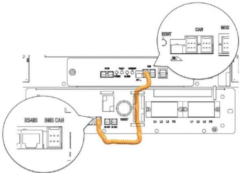
text_image
RS485 BMS CAN RETURN L1 L2 L3 F0 L1 L2 L3 F0 RETURN L1 L2 L3 F0 RENT CAM MODEFigure 5-100: BMS CAN Cable from SMPS Assembly to Switchgear
- Connect the TCP/IP Cable.

text_image
TCP/IP L1 L2 L3 R0 L1 L2 L3 R0 M887 62.62Figure 5-101: TCP/IP Cable
- Connect the dry contact cable.
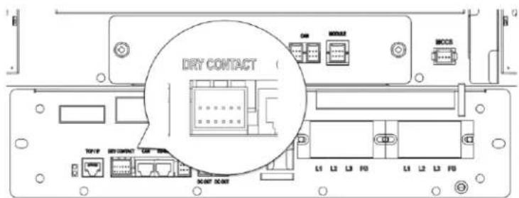
text_image
DRY CONTACT L1 L2 L3 F0 L4 L2 L3 F0Figure 5-102: Dry Contact Cable
- Remove the protective covers from the AC input terminals.

text_image
Technical diagram of an electronic device with labeled components and directional arrows indicating motion or movement.Figure 5-103: AC Input Terminals
- Connect each AC input in the SMPS Assembly. Make sure the AC cables are not energized. ^1
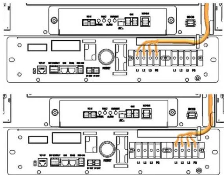
text_image
Technical diagram of server rack front panels with labeled ports and connectors, showing internal wiring connections.Figure 5-104: AC Input Terminals with Cables Attached
- Reattach the protective covers to the AC input terminals.
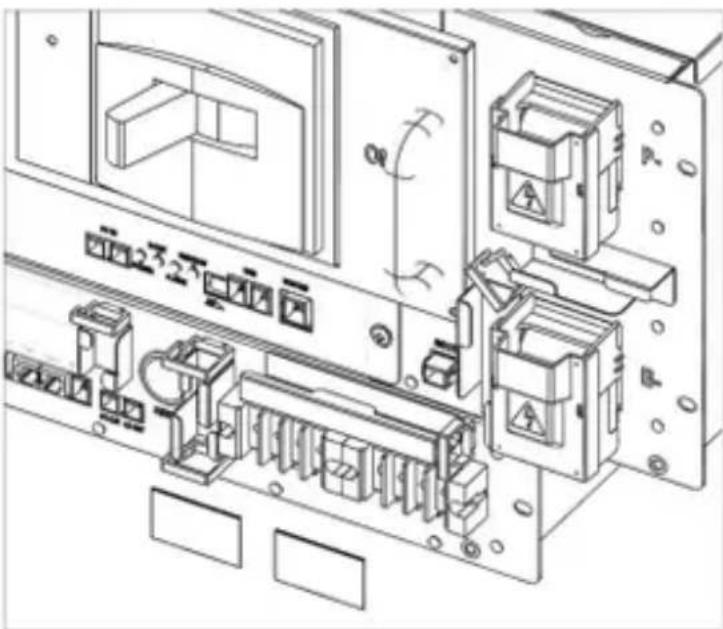
natural_image
Technical line drawing of an electronic device rear panel with components and wiring (no text or symbols)Figure 5-105: AC Input Terminals Protective Cover
- Turn on the AC input to the SMPS Assembly.
- Check the indicator LED and make sure it is in normal status.
- Turn the MCCB handle to the "ON" position.

text_image
Technical diagram of an electronic device layout with labeled components and control buttonsFigure 5-106: MCCB Handle in "ON" Position
- For SMPS Assembly Type A, the System BMS inside the replacement switchgear must be configured according to the battery system configuration. Refer to the installation manual for details.
5.3.6 Module BMS Replacement
 | CAUTION |
| Follow the instructions exactly to protect the Module BMS and Battery Module from damage.DO NOT deviate from the sequence of the steps below.The voltage of the connected system increases proportionally as battery modules are connected. Exercise extreme caution to prevent the terminals from touching anything other than their intended mounting points.Exercise extreme caution to prevent terminals and wires from contacting a wire or terminal with the opposite polarity.Do not permit either battery terminal to contact the rack frame because it is possible to contact a connection with the opposite polarity. |
- Remove the wire harnesses that are connected to "IN" and "OUT" ports.

text_image
SAMSUNG SDI ESS IN OUTFigure 5-107. Battery module
-
Troubleshooting, Repair and Replacement
-
Remove the front cover of the battery module

natural_image
Technical line drawing of an electrical enclosure or enclosure with multiple panels and mounting brackets (no text or symbols)Figure 5-108. Battery module with front cover removed
- Disconnect the voltage and temperature sensing connectors.
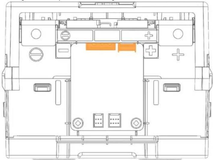
natural_image
Top-down schematic of a device layout with labeled components (no text or symbols)Figure 5-109. Voltage and temperature sensing connectors
- Remove the two screws on the Module BMS

natural_image
Top-down technical diagram of a device casing with labeled buttons and ports (no readable text or symbols)Figure 5-110. Remove the two screws
- Lift the Module BMS from the battery module.
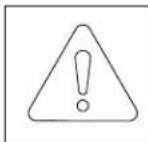
NOTICE
- Four hooking points hold the Module BMS in place. Use care when removing and installing the Module BMS to prevent the hooks from damage.

natural_image
Technical line drawing of an electrical enclosure with a red highlighted component and arrow indicating direction (no text or symbols)Figure 5-111. Remove the Module BMS from battery module
-
Troubleshooting, Repair and Replacement
-
Reverse the steps above to replace the Module BMS.
5.3.7 Module Voltage Sensing Wire Replacement
 | CAUTION |
| Follow the instructions exactly to protect the Module BMS and Battery Module from damage.DO NOT deviate from the sequence of the steps below.The voltage of the connected system increases proportionally as battery modules are connected. Exercise extreme caution to prevent the terminals from touching anything other than their intended mounting points.Exercise extreme caution to prevent terminals and wires from contacting a wire or terminal with the opposite polarity.Do not permit either battery terminal to contact the rack frame because it is possible to contact a connection with the opposite polarity. |
- Identify the defective Battery Module's type. The correct voltage sensing wire must be prepared according to the Battery Module's Type. Type A's positive (+) terminal is on the right side when viewed from the front; Type B's positive (+) terminal is on the left.
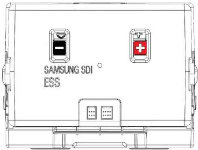
text_image
SAMSUNG SDI ESSFigure 5-112: Battery Module Type A
5. Troubleshooting, Repair and Replacement
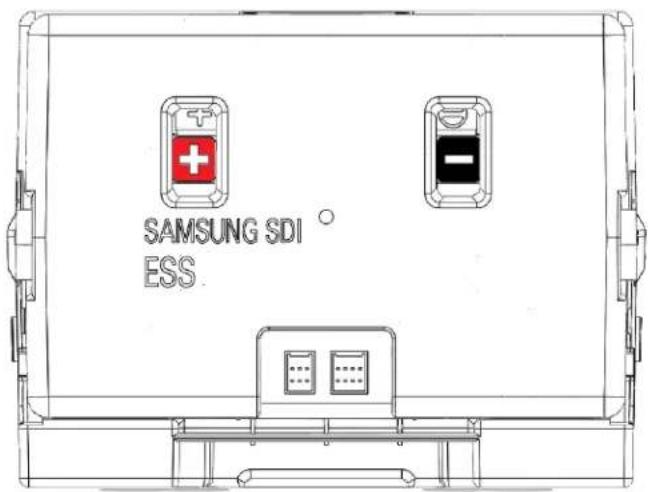
text_image
SAMSUNG SDI ESSFigure 5-113: Battery Module Type B
- Turn the MCCB off by pushing the MCCB handle to the "OFF" position.
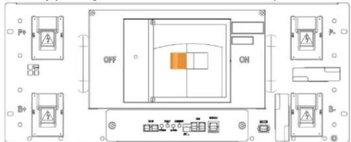
text_image
OFF ONFigure 5-114: MCCB Handle in "OFF" Position
- Turn off the AC input to the SMPS Assembly.
- Disconnect the control cables from the defective Battery Module.

natural_image
Architectural line drawings of building layouts with orange pipes and structural elements, shown in two circular views (no text or symbols)Figure 5-115: Battery Module Signal Cables
- Remove the front covers from the defective Battery Module and adjacent Battery Modules.
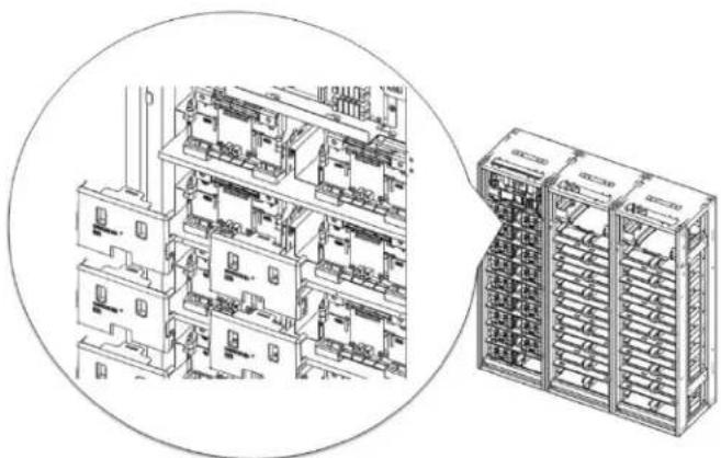
natural_image
Technical line drawing of a multi-level industrial control room with internal components and a separate rack-mounted unit (no text or symbols visible)Figure 5-116: Battery Module Front Covers
- Unbolt the positive and negative busbars from the terminals on the defective Battery Module and the adjacent battery modules.
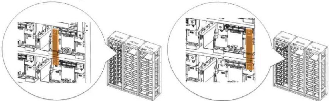
natural_image
Technical line drawings of industrial electrical equipment showing internal components and assembly (no text or symbols)Figure 5-117: Busbars on Positive and Negative Terminals
-
Remove the two busbars.
-
Using a rod (a long screwdriver of at least 254mm [10 in.] long may be used), pivot the guide in the Rack Frame to separate the hooks on the Battery Module from the matching hole in the rack frame.
5. Troubleshooting, Repair and Replacement
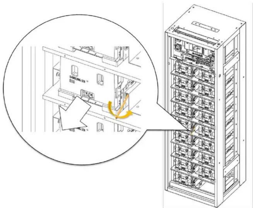
text_image
SAMSUNG SIM E68 GNDFigure 5-118: Pivoting the Guide and Pulling the Battery Module Out
- Pull out the Battery Module while pivoting the guide and remove the Battery Module from the rack frame.
- Remove the front cover of the battery module

natural_image
Isometric technical line drawing of a multi-level electrical enclosure or enclosure with no visible text or symbolsFigure 5-119. Battery module with front cover removed
- Disconnect the voltage and temperature sensing connectors.

natural_image
Top-down technical line drawing of a device interior with no visible text or symbolsFigure 5-120. Voltage and temperature sensing connectors
- Remove the two screws on the Module BMS
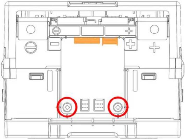
natural_image
Top-down technical diagram of a device chassis with labeled components and two red circles highlighting specific areas (no text or symbols present)Figure 5-121. Remove the two screws
- Lift the Module BMS from the battery module.
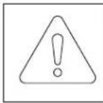
NOTICE
- Four hooking points hold the Module BMS in place. Use care when removing and installing the Module BMS to prevent the hooks from damage.
5. Troubleshooting, Repair and Replacement
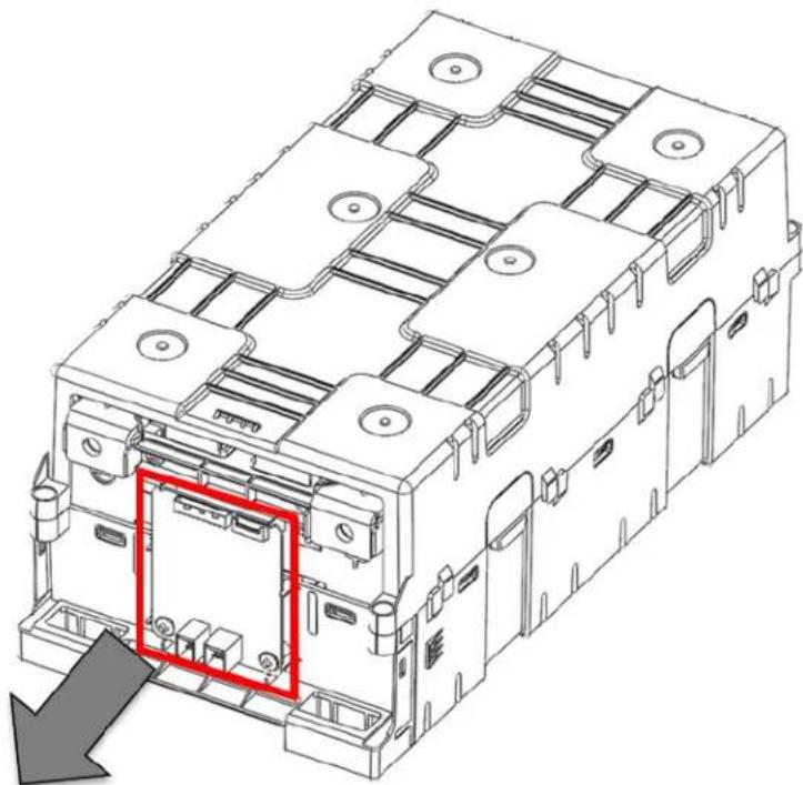
natural_image
Technical line drawing of an electrical enclosure with a red highlighted component (no text or symbols)Figure 5-122. Remove the Module BMS from battery module
14. Unscrew the four Top Case screws
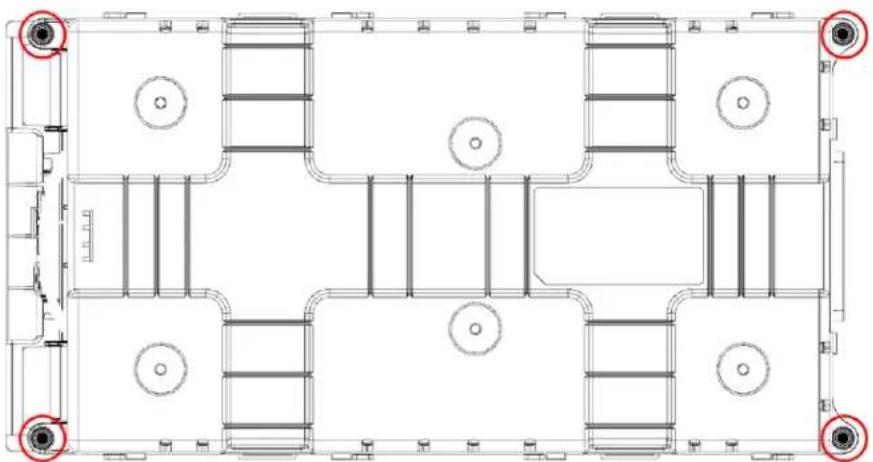
natural_image
Architectural floor plan showing room layouts and structural elements (no text or labels)Figure 5-123. Unscrew the Four Top Case Screws
15. Remove the Top Case
natural_image
Isometric technical diagram of a mechanical assembly with orange structural layers and an upward arrow indicating motion (no text or symbols present)Figure 5-124. Remove the Top Case
- Locate the voltage sensing wire connections on the bus bar.
Type A

text_image
Technical diagram of an electronic device interior with labeled ports (B1–B7) and red circular annotations indicating specific components.Figure 5-125. Module Type A Voltage Sensing Connections
Type B
5. Troubleshooting, Repair and Replacement
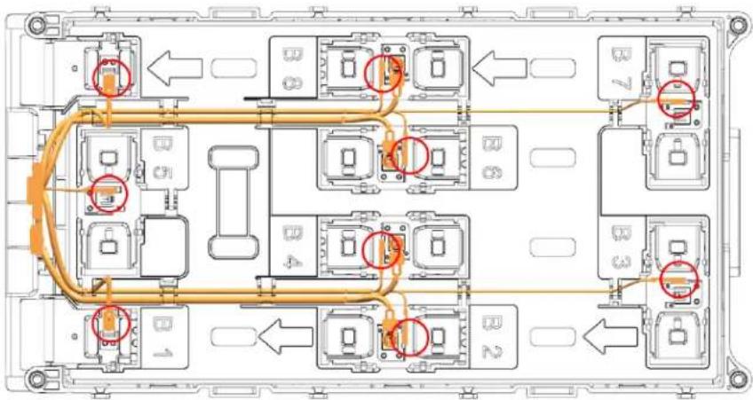
flowchart
graph TD
    A["Component B1"] --> B["Component B2"]
    B --> C["Component B3"]
    C --> D["Component B4"]
    D --> E["Component B5"]
    E --> F["Component B6"]
    F --> G["Component B7"]
    style A fill:#f9f,stroke:#333
    style B fill:#f9f,stroke:#333
    style C fill:#f9f,stroke:#333
    style D fill:#f9f,stroke:#333
    style E fill:#f9f,stroke:#333
    style F fill:#f9f,stroke:#333
    style G fill:#f9f,stroke:#333
Figure 5-126. Module Type B Voltage Sensing Connections
- Remove all connections of the voltage sensing wire. Lightly press on the tab to unhook the connection and pull to remove.
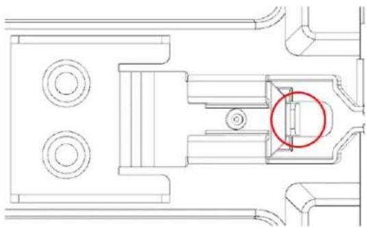
natural_image
Technical line drawing of a mechanical assembly with circular components and a highlighted section (no text or symbols)Figure 5-127. Tab on the Voltage Sensing Connection
- Connect the replacement voltage sensing wire harness by inserting the hook to the bus bar. Insert until there is a light "click". Pull lightly to make sure the connection is secure. Refer to the figure below for the correct location of the connections
Type A

text_image
Technical diagram of a vehicle electrical panel layout with labeled components and directional arrows indicating connectionsFigure 5-128. Module Type A Voltage Sensing Connections
Type B
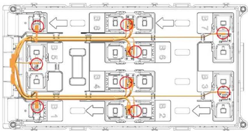
text_image
Technical diagram of an electronic device rear panel with labeled components and red-circled ports indicating specific areas.Figure 5-129. Module Type B Voltage Sensing Connections
| CAUTION | |
| The wires are labeled with the number of the connections to the Module BMS. If they are incorrectly connected to the bus bar, the Battery Module and the Module BMS will be damaged. |
- Assemble the Top Case and assemble the four Top Case screws.
5. Troubleshooting, Repair and Replacement
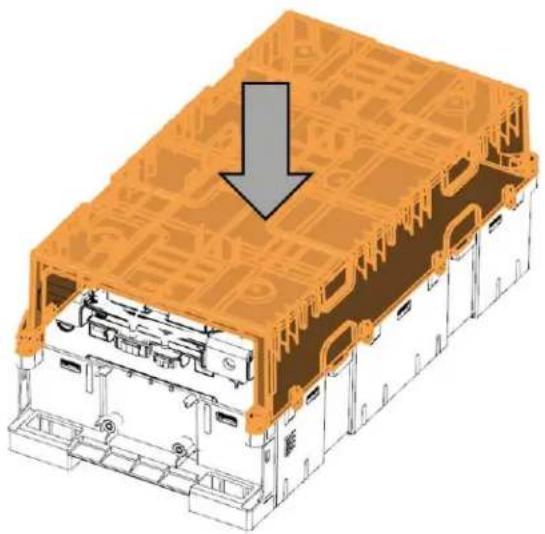
natural_image
Isometric technical diagram of a device housing with orange structural components and a gray downward arrow indicating a component (no text or symbols present)Figure 5-130. Assemble the Top Case

natural_image
Architectural floor plan showing room layouts and structural elements (no text or labels)Figure 5-131. Assemble Four Top Case Screws
- Assemble the Module BMS and assemble the two screws.
5. Troubleshooting, Repair and Replacement
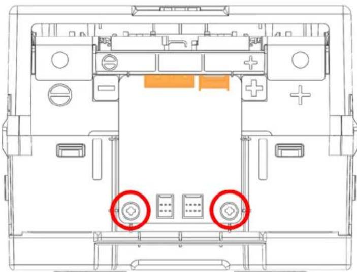
natural_image
Top-down technical diagram of a device chassis with labeled buttons and ports (no readable text or symbols)Figure 5-132. Module BMS Screws
- Assemble the Voltage and Temperature sensing connectors

natural_image
Top-down schematic of a device layout with labeled components (no text or symbols)Figure 5-133. Voltage and Temperature Sensing Connectors
- Assemble the Front Cover.
-
Insert the replacement Battery Module.
-
Troubleshooting, Repair and Replacement
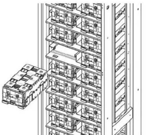
natural_image
Technical line drawing of a multi-level industrial or warehouse rack system with no visible text or symbolsFigure 5-134: Inserting the Replacement Battery Module
- Remove the front cover from the replacement Battery Module and from adjacent Battery Module.

natural_image
Technical line drawing of a multi-level industrial control room with internal compartments and a separate rack unit (no text or symbols)Figure 5-135: Removing the Front Covers
- Install the busbars.

natural_image
Technical line drawings of industrial electrical equipment layout, showing internal components and assembly steps (no text or labels)Figure 5-136: Busbars
- Reattach the front cover to the Battery Modules.
5. Troubleshooting, Repair and Replacement

natural_image
Technical line drawing of a multi-level industrial control room with internal components and a separate rack-mounted unit (no text or symbols visible)Figure 5-137: Reattaching the Front Cover to the Battery Module
- Reconnect the signal cables.
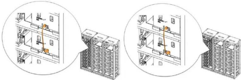
natural_image
Technical line drawing showing three views of a server rack with orange connectors, no text or symbols present.Figure 5-138: Connecting the Signal Cables
- Turn on the AC input to the SMPS Assembly.
- Check the indicator LED and make sure it is in normal status.
- Turn the MCCB handle to the "ON" position.

text_image
OFF ONFigure 5-139: MCCB Handle in "ON" Position
5.3.8 Module Temperature Sensing Wire Replacement
 | CAUTIONFollow the instructions exactly to protect the Module BMS and Battery Module from damage.DO NOT deviate from the sequence of the steps below.The voltage of the connected system increases proportionally as battery modules are connected. Exercise extreme caution to prevent the terminals from touching anything other than their intended mounting points.Exercise extreme caution to prevent terminals and wires from contacting a wire or terminal with the opposite polarity.Do not permit either battery terminal to contact the rack frame because it is possible to contact a connection with the opposite polarity. |
- Repeat steps 1 to 15 of 5.3.7 Module Voltage Sensing Wire Replacement
- Locate the voltage sensing wire connections on the bus bar.
Type A

text_image
Technical diagram of an electronic device layout with labeled ports and connections, showing internal components and directional arrows.Figure 5-140. Module Type A Temperature Sensing Connections
Type B
5. Troubleshooting, Repair and Replacement

flowchart
graph TD
    A["Module B1"] -->|Orange Cable Flow| B["Module B2"]
    B --> C["Module B3"]
    C --> D["Module B4"]
    D --> E["Module B5"]
    E --> F["Module B6"]
    F --> G["Module B7"]
    G --> H["Module B8"]
    H --> I["Output"]
    style A fill:#f9f,stroke:#333
    style B fill:#f9f,stroke:#333
    style C fill:#f9f,stroke:#333
    style D fill:#f9f,stroke:#333
    style E fill:#f9f,stroke:#333
    style F fill:#f9f,stroke:#333
    style G fill:#f9f,stroke:#333
    style H fill:#f9f,stroke:#333
    style I fill:#f9f,stroke:#333
Figure 5-141. Module Type B Temperature Sensing Connections
- Remove all connections of the temperature sensing wire. Lightly pull the tab on the bus bar to unhook the connection and pull the wire to remove.

natural_image
Pure mechanical assembly diagram without any text, numbers, or symbolsFigure 5-142. Tab on Temperature Sensing Connection

NOTICE
- If the tab on the bus bar is pulled too much during removal, the tab will not be able to flex back to its original position and will not be tight enough to adequately fix the replaced temperature sensing wire.
- Connect the replacement temperature sensing wire harness. Refer to the figure below for the correct location of the connections Type A
5. Troubleshooting, Repair and Replacement

text_image
Technical diagram of an electronic device layout with labeled ports and connections, including B1 to B8 and directional arrows.Figure 5-143. Module Type A Temperature Sensing Connections
Type B
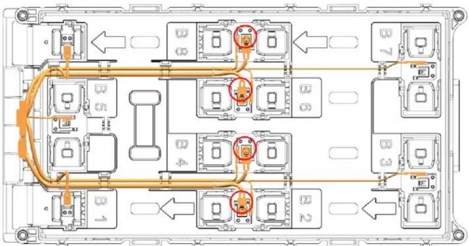
flowchart
graph TD
    A["Module 1"] --> B["Component 2"]
    B --> C["Component 3"]
    C --> D["Component 4"]
    D --> E["Component 5"]
    E --> F["Component 6"]
    F --> G["Component 7"]
    H["Port 1"] --> I["Component 2"]
    J["Port 2"] --> K["Component 3"]
    L["Port 3"] --> M["Component 4"]
    N["Port 4"] --> O["Component 5"]
    P["Port 5"] --> Q["Component 6"]
    R["Port 6"] --> S["Component 7"]
    T["Port 7"] --> U["Component 8"]
Figure 5-144. Module Type B Temperature Sensing Connections
CAUTION
- The wires are labeled with the number of the connections to the Module BMS. If they are incorrectly connected to the bus bar, the Battery Module and the Module BMS will be damaged.
- Return to step 19 of 5.3.7 Module Voltage Sensing Wire Replacement to reassemble the serviced Battery Module to the rack.
6. Appendix
6.1 Disposal and Recycling
For recycling, contact the manufacturer.
Contaminated packaging must be disposed in accordance with local regulations.
Memo
Memo
Memo
www.SamsungSDI.com