EWWS530DZXSA1 - Air-conditioner DAIKIN - Free user manual and instructions
Find the device manual for free EWWS530DZXSA1 DAIKIN in PDF.

User questions about EWWS530DZXSA1 DAIKIN
0 question about this device. Answer the ones you know or ask your own.
Ask a new question about this device
Download the instructions for your Air-conditioner in PDF format for free! Find your manual EWWS530DZXSA1 - DAIKIN and take your electronic device back in hand. On this page are published all the documents necessary for the use of your device. EWWS530DZXSA1 by DAIKIN.
USER MANUAL EWWS530DZXSA1 DAIKIN
| REV | 02 |
| Date | February 2021 |
| Supersedes | D-EOMWC01405-19_01EN |
Operating Manual
D-EOMWC01405-19_02EN
WATER COOLED OIL FREE CENTRIFUGAL CHILLERS
TABLE OF CONTENTS
1 SAFETY CONSIDERATIONS....5
1.1 General....5
1.2 Before switching the unit....5
1.3 Avoid electrocution....5
2 GENERAL DESCRIPTION 6
2.1 Basic Information 6
2.2 Abbreviations used....6
2.3 Controller Operating Limits 6
2.4 Controller Architecture 6
2.5 Communication Modules....7
3 USING THE CONTROLLER....7
3.1 Navigating 9
3.2 Passwords....9
3.3 Editing 9
3.4 Basic Control System Diagnostic....9
3.5 Controller maintenance....10
3.6 Optional Remote User Interface 11
3.7 Embedded Web Interface 11
4 MENU STRUCTURE....13
4.1 Main Menu 13
4.2 View/Set Unit....13
4.2.1 Thermostat Ctrl....13
4.2.2 Network Ctrl 14
4.2.3 Pumps....14
4.2.4 Condenser 14
4.2.5 Evaporator 15
4.2.6 Master/Slave 15
4.2.6.1 Data.... 15
4.2.6.2 Options 16
4.2.6.3 Thermostat Ctrl 16
4.2.6.4 Timers 16
4.2.6.5 Standby Chiller....16
4.2.7 Rapid Restart....17
4.2.8 Date/Time 17
4.2.9 Scheduler....17
4.2.10 Power Conservation 17
4.2.11 Controller IP setup....18
4.2.12 Daikin on Site 18
4.2.13 Software Options 19
4.2.13.1 Changing the Password for buying new Software Options 19
4.2.13.2 Inserting the Password in a Spare Controller 19
4.2.13.3 Modbus MSTP Software Option 21
4.2.13.4 BACNET MSTP 22
4.2.13.5 BACNET IP 23
4.2.14 Menu Password....23
4.3 Active Setpoint....24
4.4 Evaporator LWT 24
4.5 Condenser LWT 24
4.6 Unit Capacity 24
4.7 Unit Mode 24
4.8 Unit Enable 25
4.9 Timers 25
4.10 Alarms 25
4.11 Commission Unit 25
4.11.1 Alarm Limits....25
4.11.2 Calibrate Sensors 26
4.11.2.1 Unit Calibrate Sensors 26
4.11.2.2 Compressor Calibrate Sensors.... 26
4.11.3 Scheduled Maintenance 26
4.12 About this Chiller 26
5 WORKING WITH THIS UNIT 27
5.1 Unit Setup 27
5.1.1 Control Source....27
5.1.2 Available Mode Setting....27
It has to be noted that in case the selected mode cannot be managed by the unit, it will revert to Cool. 28
5.1.3 Temperature Settings 28
5.1.3.1 LWT Setpoint Setting 28
5.1.3.2 Thermostat Control Settings 28
5.1.3.3 Pumps 29
5.1.4 Power Conservation 29
5.1.4.1 Demand Limit 29
5.1.4.2 Current Limit (Optional) 30
5.1.4.3 Setpoint Reset 30
5.1.4.4 Setpoint Reset by External 4-20 mA Signal....30
5.1.4.5 Setpoint Reset by Evaporator Return Temperature 30
5.1.4.6 Soft Load 31
5.1.5 Date/Time 31
5.1.5.1 Date, Time and UTC Settings 31
5.1.6 Scheduler....31
5.2 Unit Start-up 31
5.2.1 Unit Status 31
5.2.2 Prepare the unit to start....32
5.2.2.1 Unit Switch Enable 32
5.2.3 Keypad Enable 32
5.2.3.1 BMS Enable 32
5.3 Condensation Control 33
6 ALARMS AND TROUBLESHOOTING....34
6.1 Unit Alerts....34
6.1.1 Bad Demand Limit Input 34
6.1.2 Bad Leaving Water Temperature Reset Input 34
6.1.3 Condenser Pump #1 Failure (W/C units only) 35
6.1.4 Condenser Pump #2 Failure (W/C units only) 35
6.1.5 Evaporator Pump #1 Failure 35
6.1.6 Evaporator Pump #2 Failure....36
6.1.7 External Event 36
6.1.8 Password Over Time....36
6.2 Unit Pumpdown Stop Alarms 37
6.2.1 Condenser Entering Water Temperature (EWT) sensor fault 37
6.2.2 Condenser Leaving Water Temperature (LWT) sensor fault 37
6.2.3 Evaporator Entering Water Temperature (EWT) sensor fault 37
6.2.4 Evaporator Water Temperatures inverted 38
6.2.5 Liquid Temperature Sensor fault 38
6.3 Unit Rapid Stop Alarms 39
6.3.1 PVM alarm (A/C units only) 39
6.3.2 Condenser Water Freeze alarm (W/C units only) 39
6.3.3 Condenser Water Flow Loss alarm (W/C units only) 39
6.3.4 Emergency Stop 40
6.3.5 Evaporator Flow Loss alarm....40
6.3.6 Evaporator Leaving Water Temperature (LWT) sensor fault 40
6.3.7 Evaporator Water Freeze alarm 41
6.3.8 External alarm 41
6.3.9 Gas Leakage Alarm 41
6.3.10 Power Fault....42
6.3.11 Low Discharge Superheat 42
6.3.12 Mechanical High Pressure Switch Alarm 43
6.3.13 High Pressure Alarm 43
6.3.14 Low Pressure Alarm 44
6.3.15 Compressor Extension Communication Error 45
6.3.16 EXV Driver Extension Communication Error 45
6.3.1 Hot Gas Bypass Driver Extension Communication Error 45
6.4 Compressor Alerts 46
6.4.1 Power Loss 46
6.5 Circuit Pumpdown Stop Alarms 46
6.5.1 Low Discharge Superheat fault 46
6.5.2 Suction Temperature Sensor fault 46
6.6 Circuit Rapid Stop Alarms 47
6.6.1 Compressor VFD Fault....47
6.6.2 High Motor Current Alam 47
6.6.3 High Motor Temperature Alarm....47
6.6.4 Overvoltage Alarm 48
6.6.5 Undervoltage Alarm 48
6.6.6 Compressor Lockout Fault 48
6.6.7 Compressor Fault 49
6.6.1 Compressor Sensor Fault 49
6.6.2 BMC Fault....49
6.6.3 Suction Pressure Sensor Fault....50
6.6.4 Discharge Pressure Sensor Fault 50
6.6.5 Check Valve Leakage....50
6.6.6 Compressor Bearing Fault....51
6.6.7 Discharge Temperature Sensor Fault 51
6.6.8 VFD Communication Failure 51
7 OPTIONS....52
7.1 Energy Meter including Current Limit (Optional) 52
7.2 Rapid Restart (Optional) 52
1.1 General
Installation, start-up and servicing of equipment can be hazardous if certain factors particular to the installation are not considered: operating pressures, presence of electrical components and voltages and the installation site (elevated plinths and built-up up structures). Only properly qualified installation engineers and highly qualified installers and technicians, fully trained for the product, are authorized to install and start-up the equipment safely.
During all servicing operations, all instructions and recommendations, which appear in the installation and service instructions for the product, as well as on tags and labels fixed to the equipment and components and accompanying parts supplied separately, must be read, understood and followed.
Apply all standard safety codes and practices.
Wear safety glasses and gloves.
Use the proper tools to move heavy objects. Move units carefully and set them down gently.

Do not operate on a faulty fan, pump or compressor before the main switch has been shut off. Overtemperature protection is auto-reset, therefore the protected component may restart automatically if temperature conditions allow it.
In some unit a push button is placed on a door of the unit electrical panel. The button is highlighted by a red color in yellow background. A manual pressure of the emergency stop button stops all loads from rotating, thus preventing any accident which may occur. An alarm is also generated by the Unit Controller. Releasing the emergency stop button enables the unit, which may be restarted only after the alarm has been cleared on the controller.

The emergency stop causes all motors to stop, but does not switch off power to the unit. Do not service or operate on the unit without having switched off the main switch.
1.2 Before switching the unit
Before switching on the unit read the following recommendations:
- When all the operations and all the settings have been carried out, close all the switchbox panels
- The switchbox panels can only be opened by trained personnel
- When the UC requires to be accessed frequently the installation of a remote interface is strongly recommended
- LCD display of the unit controller may be damaged by extremely low temperatures (see chapter 2.4). For this reason, it is strongly recommended to never power off the unit during winter, especially in cold climates.
1.3 Avoid electrocution
Only personnel qualified in accordance with IEC (International Electrotechnical Commission) recommendations may be permitted access to electrical components. It is particularly recommended that all sources of electricity to the unit be shut off before any work is begun. Shut off main power supply at the main circuit breaker or isolator.
IMPORTANT: This equipment uses and emits electromagnetic signals. Tests have shown that the equipment conforms to all applicable codes with respect to electromagnetic compatibility.

RISK OF ELECTROCUTION: Even when the main circuit breaker or isolator is switched off, certain circuits may still be energized, since they may be connected to a separate power source.

RISK OF BURNS: Electrical currents cause components to get hot either temporarily or permanently. Handle power cable, electrical cables and conduits, terminal box covers and motor frames with great care.

ATTENTION: In accordance with the operating conditions the fans can be cleaned periodically. A fan can start a any time, even if the unit has been shut down.
2.1 Basic Information
MicroTech is a system for controlling single or dual-circuit air/water-cooled liquid chillers. MicroTech controls compressor start-up necessary to maintain the desired heat exchanger leaving water temperature. In each unit mode it controls the operation of the condensers to maintain the proper condensation process in each circuit.
Safety devices are constantly monitored by MicroTech to ensure their safe operation. MicroTech also gives access to a Test routine covering all inputs and outputs. All MicroTech controls can work in accordance with three independent modes:
- Local mode: the machine is controlled by commands from the user interface.
- Remote mode: the machine is controlled by remote contacts (volt-free contacts).
- Network mode: the machine is controlled by commands from a BAS system. In this case, a data communication cable is used to connect the unit to the BAS.
When the MicroTech system operates autonomously (Local or Remote mode) it retains all of its own control capabilities but does not offer any of the features of the Network mode. In this case monitoring of the unit operational data is still allowed.
2.2 Abbreviations used
In this manual, the refrigeration circuits are called circuit #1 and circuit #2. The compressor in circuit #1 is labelled Cmp1. The other in circuit #2 is labelled Cmp2. The following abbreviations are used:
| A/C | Air Cooled |
| CEWT | Condenser Entering Water Temperature |
| CLWT | Condenser Leaving Water Temperature |
| CP | Condensing Pressure |
| CSRT | Condensing Saturated Refrigerant Temperature |
| DSH | Discharge Superheat |
| DT | Discharge Temperature |
| E/M | Energy Meter Module |
| EEWT | Evaporator Entering Water Temperature |
| ELWT | Evaporator Leaving Water Temperature |
| EP | Evaporating Pressure |
| ESRT | Evaporating Saturated Refrigerant Temperature |
| EXV | Electronic Expansion Valve |
| HMI | Human Machine Interface |
| MOP | Maximum operating pressure |
| SSH | Suction SuperHeat |
| ST | Suction Temperature |
| UC | Unit controller (MicroTech) |
| W/C | Water Cooled |
2.3 Controller Operating Limits
Operation (IEC 721-3-3):
• Temperature -40...+70 °C
• Restriction LCD -20... +60 °C
• Restriction Process-Bus -25....+70 °C
• Humidity < 90 % r.h (no condensation)
• Air pressure min. 700 hPa, corresponding to max. 3,000 m above sea level
Transport (IEC 721-3-2):
• Temperature -40...+70 °C
• Humidity < 95 % r.h (no condensation)
• Air pressure min. 260 hPa, corresponding to max. 10,000 m above sea level.
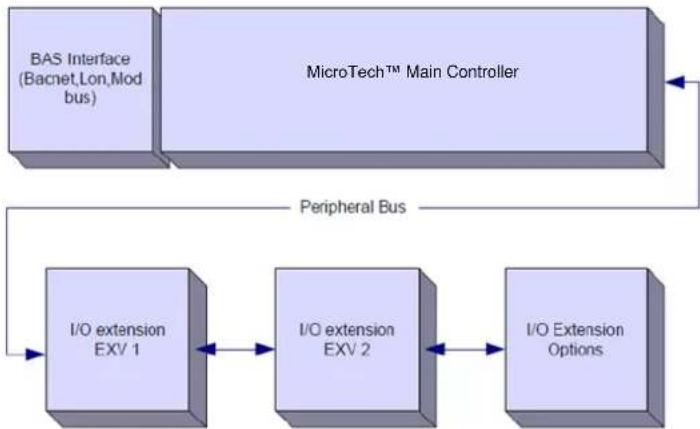
2.4 Controller Architecture
The overall controller architecture is the following:
• One MicroTech main controller
- I/O extensions as needed depending on the configuration of the unit
- Communications interface(s) as selected
- Peripheral Bus is used to connect I/O extensions to the main controller.
flowchart
graph TD
    A["BAS Interface (Bacnet Lon, Mod bus)"] --> B["MicroTech™ Main Controller"]
    B --> C["Peripheral Bus"]
    C --> D["I/O extension EXV 1"]
    D --> E["I/O extension EXV 2"]
    E --> F["I/O Extension Options"]
    F --> D
    B --> G["External Bus"]
| Controller/Extension Module | Siemens Part Number | Address | Usage |
| EWWD/H-VZ | |||
| Main Controller | POL687.00/MCQ | n/a | Used on all configurations |
| Extension Module | POL965.00/MCQ | 2 | Used on all configurations |
| EEXV Module 1 | POL94U.00/MCQ | 3 | Used on all configurations |
| EEXV Module 2 | POL94U.00/MCQ | 7 | Used on some configurations |
| HGBP Module | POL94U.00/MCQ | 5 | Optional |
All boards are supplied from a common 24 Vac source. Extension boards can be directly powered by the Unit Controller. All boards can be also supplied by a 24Vdc source.

CAUTION: Maintain the correct polarity when connecting the power supply to the boards, otherwise the peripheral bus communication will not operate and the boards may be damaged.
2.5 Communication Modules
Any of the following modules can be connected directly to the left side of the main controller to allow a BAS or other remote interface to function. Up to three can be connected to the controller at a time. The controller should automatically detect and configure itself for new modules after booting up. Removing modules from the unit will require manually changing the configuration.
| Module | Siemens Part Number | Usage |
| BacNet/IP | POL908.00/MCQ | Optional |
| Lon | POL906.00/MCQ | Optional |
| Modbus | POL902.00/MCQ | Optional |
| BACnet/MSTP | POL904.00/MCQ | Optional |
The control system consists of a unit controller (UC) equipped with a set of extension modules that implement additional features. All boards communicate via an internal peripheral bus with the UC. The UC continuously manages the information received from the various pressure and temperature probes installed on the unit. The UC incorporates a program that controls the unit.
TCP/IP Port
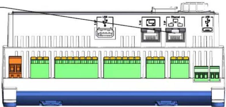
text_image
Diagram of an electronic device rack with labeled components including USB, switch, and battery cellsMicroTech, POL688.80 Controller

text_image
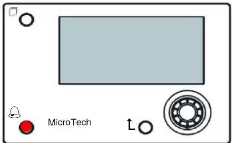
Menu Button Back Button Alarm Button Navigation Wheel MicroTech®4 MT3106Inbuilt HMI (A/C units)
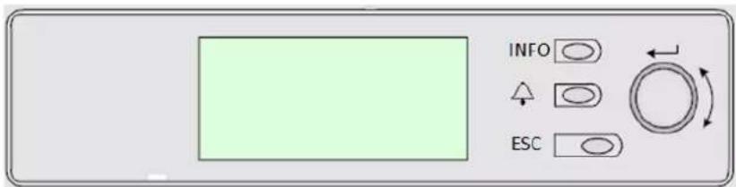
text_image
INFO ESCThis HMI is provided of three buttons and one wheel button.
| Alarm status (from any page it links with the page with alarm list, alarm log and alarm snapshot if available) | |
| INFO | Back to Main Page |
| ESC | Back to the previous level (it can be the Main Page) |
| Wheel Button | Used to scroll between the different menu pages, settings and data available on the HMI for the active password level. Rotating the wheel allows to navigate between lines on a screen (page) and to increase and decrease changeable values when editing. Pushing the wheel acts as an Enter Button and will jump from a link to the next set of parameters. |
3.1 Navigating
When power is applied to the control circuit, the controller screen will be active and display the Home screen, which can also be accessed by pressing the Menu Button. The navigating wheel is the only navigating device necessary, although the MENU, ALARM, and BACK buttons can provide shortcuts as explained previously.
An example of the HMI screens is shown in the following picture.
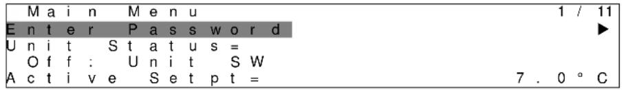
text_image
M a i n M e n u 1 / 11 E n t e r P a s s w o r d ► U n i t S t a t u s = O f f : U n i t S W A c t i v e S e t p t = 7 . 0 ° CA bell ringing in the top right corner will indicate an active alarm. If the bell doesn't move it means that the alarm has been acknowledged but not cleared because the alarm condition hasn't been removed. A LED will also indicate where the alarm is located between the unit or circuits.

text_image
M a i n M e n u 1 / E n t e r P a s s w o r d U n i t S t a t u s = O f f : U n i t S W A c t i v e S e t p t = 7 . 0 ° CThe active item is highlighted in contrast, in this example the item highlighted in Main Menu is a link to another page. By pressing the push'n'roll, the HMI will jump to a different page. In this case the HMI will jump to the Enter Password page.
text_image
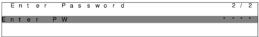
Enter Password 2 / 2 Enter PW * * * *3.2 Passwords
The HMI structure is based on access levels that means that each password will disclose all the settings and parameters allowed to that password level. Basic informations about the status can be accessed without the need to enter the password. The user UC handles two level of passwords:
| USER | 5321 |
| MAINTENANCE | 2526 |
The following information will cover all data and settings accessible with the maintenance password. User password will disclose a subset of the settings explained in chapter 4.
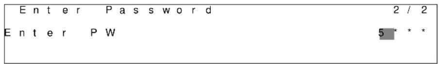
In the Enter Password screen, the line with the password field will be highlighted to indicate that the field on the right can be changed. This represents a setpoint for the controller. Pressing the push'n'roll the individual field will be highlighted to allow an easy introduction of the numeric password. By changing all fields, the 4 digits password will be entered and, if correct, the additional settings available with that password level will be disclosed.
text_image
Enter Password 2 / 2 Enter PW 5 * * *The password will time out after 10 minutes and is cancelled if a new password is entered or the control powers down. Entering an invalid password has the same effect as continuing without a password. It is changeable from 3 to 30 minutes via the Timer Settings menu in the Extended Menus.
3.3 Editing
The Editing Mode is entered by pressing the navigation wheel while the cursor is pointing to a line containing an editable field. Once in the edit mode pressing the wheel again causes the editable field to be highlighted. Turning the wheel clockwise while the editable field is highlighted causes the value to be increased. Turning the wheel counter-clockwise while the editable field is highlighted causes the value to be decreased. The faster the wheel is turned, the faster the value is increased or decreased. Pressing the wheel again cause the new value to be saved and the keypad/display to leave the edit mode and return to the navigation mode.
3.4 Basic Control System Diagnostic
MicroTech controller, extension modules and communication modules are equipped with two status LED (BSP and BUS) to indicate the operational status of the devices. The BUS LED indicates the status of the communication with the controller. The meaning of the two status LED is indicated below.
Main Controller (UC)
| BSP LED | Mode |
| Solid Green | Application running |
| Solid Yellow | Application loaded but not running (*) or BSP Upgrade mode active |
| Solid Red | Hardware Error (*) |
| Flashing Green | BSP startup phase. The controller needs time for starting. |
| Flashing Yellow | Application not loaded (*) |
| Flashing Yellow/Red | Fail safe mode (in case that the BSP upgrade was interrupted) |
| Flashing Red | BSP Error (software error*) |
| Flashing Red/Green | Application/BSP update or inizialization |
(*) Contact Service.
Extension modules
| BSP LED | Mode | BUS LED | Mode |
| Solid Green | BSP running | Solid Green | Communication running, I/O working |
| Solid Red | Hardware Error (*) | Solid Red | Communication down (*) |
| Flashing Red | BSP Error (*) | Solid Yellow | Communication running but parameter from the application wrong or missing, or uncorrect factory calibration |
| Flashing Red/Green | BSP upgrade mode |
Communication modules
BSP LED (same for all modules)
| BSP LED | Mode |
| Solid Green | BPS running, communication with controller |
| Solid Yellow | BSP running, no communication with controller (*) |
| Solid Red | Hardware Error (*) |
| Flashing Red | BSP Error (*) |
| Flashing Red/Green | Application/BSP update |
(*) Contact Service.
BUS LED
| BUS LED | LON | Bacnet MSTP | Bacnet IP | Modbus |
| Solid Green | Ready for Communication. (All Parameter loaded, Neuron configured). Doesn't indicate a communication with other devices. | Ready for Communication. The BACnet Server is started. It doesn't indicate an active communication | Ready for Communication. The BACnet Server is started. It doesn't indicate an active communication | All Communication running |
| Solid Yellow | Startup | Startup | Startup. The LED stays yellow until the module receives a IP Address, therefore a link must be established. | Startup, or one configured channel not communicating to the Master |
| Solid Red | No Communication to Neuron (internal error, could be solved by downloading a new LON application) | BACnet Server down. Automatically a restart after 3 seconds are initiated. | BACnet Server down. Automatic restart after 3 seconds is initiated. | All configured Communications down. Means no communication to the Master. The timeout can be configured. In case that the timeout is zero the timeout is disabled. |
| Flashing Yellow | Communication not possible to the Neuron. The Neuron must be configured and set online over the LON Tool. |
3.5 Controller maintenance
The controller requires to maintain the installed battery. Every two years it's required to replace the battery. Battery model is: BR2032 and it is produced by many different vendors.
To replace the battery remove the plastic cover of the controller display using a screw driver as shown in the following pictures:

natural_image
Close-up of a control panel with a pen inserted, placed on a white surface with red diagonal lines (no visible text or symbols)
natural_image
Close-up of a white electronic device with a screwdriver inserted, showing ports and control panels (no visible text or symbols)
natural_image
Close-up of a device with a circular inset showing a small mechanical component, no visible text or symbols.Be careful to avoid damages to the plastic cover. The new battery shall be placed in the proper battery holder which is highlighted in the picture, respecting the polarities indicated into the holder itself.
3.6 Optional Remote User Interface
As an option an external Remote HMI can be connected on the UC. The Remote HMI offers the same features as the inbuilt display plus the alarm indication done with a light emitting diode located below the bell button.
The Remote can be ordered with the unit and shipped loose as a field installed option. It can also be ordered any time after chiller shipment and mounted and wired on the job as explained on the following page. The remote panel is powered from the unit and no additional power supply is required.
All viewing and setpoint adjustments available on the unit controller are available on the remote panel. Navigation is identical to the unit controller as described in this manual.
The initial screen when the remote is turned on shows the units connected to it. Highlight the desired unit and press the wheel to access it. The remote will automatically show the units attached to it, no initial entry is required.
text_image
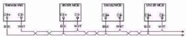
MicroTechThe Remote HMI can be extended up to 700m using the process bus connection available on the UC. With a daisy-chain connection as below, a single HMI can be connected to up to 8 units. Refer to the specific HMI manual for details.
flowchart
graph LR
    A["Resistor AM"] -->|CE+| B["Clock"]
    A -->|CE-| C["Data"]
    A -->|WHT| D["Output"]
    E["300T1 MDE"] -->|CE+| F["Clock"]
    E -->|CE-| G["Data"]
    E -->|WHT| H["Output"]
    I["UN102 MDE"] -->|CE+| J["Clock"]
    I -->|CE-| K["Data"]
    I -->|WHT| L["Output"]
    M["UN103 MDE"] -->|CE+| N["Clock"]
    M -->|CE-| O["Data"]
3.7 Embedded Web Interface
The MicroTech controller has an embedded web interface that can be used to monitor the unit when connected to a local network. It is possible to configure the IP addressing of the MicroTech as a fixed IP of DHCP depending on the network configuration.
With a common web browser a PC can connect with the unit controller entering the IP address of the controller or the host name, both visible in the "About Chiller" page accessible without entering a password.
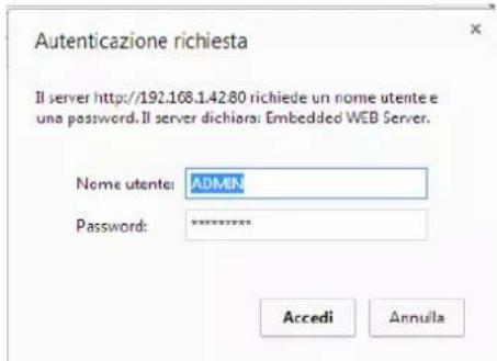
When connected, it will be required to enter a user name and a password. Enter the following credential to get access to the web interface:
User Name: ADMIN
Password: SBTAdmin!
The Main Menu page will be displayed. The page is a copy of the onboard HMI and follows the same rules in terms of access levels and structure.

text_image
Main Menu Enter Password Unit Status= Off: Unit Not Cfgd Active Setpoint= 7.0°C MS Ctrl Tmp= 0.0°C Evaporator LWT= -273.1°C Unit Capacity= 0.0% Unit Mode= CoolIn addition it allows to trend log a maximum of 5 different quantities. It's required to click on the value of the quantity to monitor and the following additional screen will become visible:
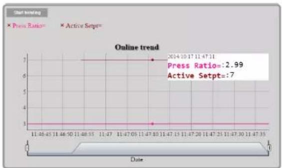
line
| Date | Press Ratio | Active Setpt | | ---------- | ----------- | ------------ | | 2014-10-17 | 2.99 | 7 |Depending on the web browser and its version the trend log feature may not be visible. It's required a web browser supporting HTML 5 like for example:
• Microsoft Internet Explorer v.11,
- Google Chrome v.37,
- Mozilla Firefox v.32.
These software are only an example of the browser supported and the versions indicated have to be intended as minimum versions.
4 MENU STRUCTURE
All settings are divided in different menus. Each menu collects in a single page other sub-menus, settings or data related to a specific function (for example Power Conservation or Setup) or entity (for example Unit or Circuit). In any of the following pages, a grey box will indicate changeable values and the defaults.
4.1 Main Menu
| Setpoint/Sub-Menu | Default | Range | Description |
| Enter Password | ▶ | - | Submenu to activate access levels |
| View/Set Unit | ▶ | - | Submenu for unit data and settings |
| View/Set Circuit | ▶ | - | Submenu for circuit data and settings |
| Unit Status= | Off: Unit Sw | AutoOff: All Cir DisabledOff: Unit AlarmOff: Keypad DisableOff: Master DisableOff: BAS DisableOff: Unit SwOff: Test ModeOff: Schedule DisableAuto: Wait For LoadAuto: Water RecirAuto: Wait For FlowAuto: PumpdnAuto: Max PulldnAuto: Unit Cap LimitAuto: Current Limit | Status of the Unit |
| Active Setpoint= | 7.0°C, ▶ | - | Water temperature active setpoint + link to Setpoint page |
| MS Ctrl Tmp= | -273.1°C, ▶ | - | Master slave controlled temperature + link to Master Slave Data page |
| Evaporator LWT= | -273.1°C, ▶ | - | Evaporator leaving water temperature + link to Temperatures page |
| Condenser LWT= | -273.1°C, ▶ | - | Condenser leaving water temperature + link to Temperatures page (W/C units only) |
| Unit Capacity= | 0.0%, ▶ | - | Unit capacity + link to Capacity page |
| Unit Mode= | Cool, ▶ | - | Unit Mode + link to Available modes page |
| Unit Enable= | Enable, ▶ | - | Unit Enable state + link to unit and circuits enable page |
| Timers | ▶ | - | Submenu for unit timers |
| Alarms | ▶ | - | Submenu for alarms; same function as Bell Button |
| Commission Unit | ▶ | - | Submenu for commission unit |
| About Chiller | ▶ | - | Application Info submenu |
4.2 View/Set Unit
| Setpoint/Sub-Menu | Default | Range | Description |
| Thermostat Ctrl | ▶ | - | Submenu for Thermostatic control |
| Network Ctrl | ▶ | - | Submenu for Network control |
| Pumps | ▶ | - | Submenu for pump settings |
| Condenser | ▶ | - | Submenu for Condenser tower control |
| Evaporator | ▶ | - | Submenu for Evaporator three way valve control |
| Master/Slave | ▶ | - | Submenu for Master Slave data and settings |
| Rapid Restart | ▶ | - | Submenu for Rapid Restart Option |
| Date/Time | ▶ | - | Submenu Date, Time and Quiet Night mode schedule |
| Scheduler | ▶ | - | Submenu for Time Scheduler |
| Power Conservation | ▶ | - | Submenu Unit Limiting functions |
| Electrical Data | ▶ | - | Submenu for electrical data |
| Ctrl IP Setup | ▶ | - | Submenu for controller IP-address setup |
| Daikin on Site | ▶ | - | Submenu for connection to Daikin cloud DoS |
| Menu Password | ▶ | - | Submenu Disable Password for User level |
4.2.1 Thermostat Ctrl
This page resumes all the parameters related to the unit thermostatic control.
| Setpoint/Sub-Menu | Default | Range | Description |
| Start Up DT= | 2.7°C | 0.0...5.0°C | Offset to start thermostat control |
| Shut Dn DT= | 1.5°C | 0.0...1.7°C | Offset to standby |
| Stg Up DT= | 0.5°C | 0.0...1.7°C | Offset to allow compressor starts |
| Stg Dn DT= | 1.0°C | 0.0...1.7°C | Offset to force one compressor off |
| Stg Up Delay= | 3 min | 0...60 min | Compressor start interstage |
| Stg Dn Delay= | 3 min | 3...30 min | Compressor stop interstage |
| Strt Strt Dly= | 15min | 15...60 min | Compressor Start to Start delay |
| Stop Strt Dly= | 3min | 3...20 min | Compressor Stop to Start delay |
| Ice Cycle Dly= | 12h | 1...23h | Ice cycle delay |
| Lt Ld Stg Dn %= | 40% | 20...50% | Circuit capacity threshold to stage down one compressor |
| Hi Ld Stg Up %= | 50% | 50...100% | Circuit capacity threshold to stage up one compressor |
| Next Cmp On= | 0 | - | Shows next circuit to be started up |
| Next Cmp Off= | 0 | - | Shows next circuit number to be stopped |
4.2.2 Network Ctrl
This page resumes all settings related to Network control.
| Setpoint/Sub-Menu | Default | Range | Description |
| Control Source= | Local | Local, Network | Control source selection: Local/BMS |
| Act Ctrl Src= | N/A | Local, Network | Active control between Local/BMS |
| Netwrk En SP= | Disable | Enable, Disable | Enable unit command from BMS |
| Netwrk Mode SP= | Cool | - | Cool, Ice, Heat (NA), Cool/Heat Recovery |
| Netwrk Cool SP= | 6.7°C | - | Cooling setpoint from BMS |
| Netwrk Cap Lim= | 100% | - | Capacity limitation from BMS |
| Network Heat SP= | 45.0°C | - | Heating setpoint from BMS |
| Remote Srv En= | Disable | Enable, Disable | Remote server enable |
4.2.3 Pumps
This page contains the settings to define the operation of the primary/backup pumps, the running hours of each pump and all parameters to configure the behavior of the pump driven with an inverter.
| Setpoint/Sub-Menu | Default | Range | Description |
| Evp Pmp Ctrl= | #1 Only | #1 Only, #2 Only, Auto, #1 Primary, #2 Primary | Set number of Evaporator pumps operational and which priority |
| Evap Recirc Tm= | 30s | 0...300s | Water recirculating timer |
| Evap Pmp 1 Hrs= | 0h | Running Hours Evaporator Pump 1 (if present) | |
| Evap Pmp 2 Hrs= | 0h | Running Hours Evaporator Pump 2 (if present) | |
| Speed 1= | N/A | 0-100% | Speed when the input Double Speed Switch is open |
| Cnd Pump Ctrl= | #1 Only | #1 Only, #2 Only, Auto, #1 Primary, #2 Primary | Set number of Condenser pumps operational and which priority |
| Cond Pmp 1 Hrs= | 0h | Running Hours Condenser Pump 1 (if present) | |
| Cond Pmp 2 Hrs= | 0h | Running Hours Condenser Pump 2 (if present) |
4.2.4 Condenser
This page contains basics settings for condensation control described in section 5.3.
| Setpoint/Sub-Menu | Default | Range | Description |
| Cond LWT | -273.1°C | - | Present value of Condenser Leaving Water Temperature |
| Cond EWT | -273.1°C | - | Present value of Condenser Entering Water Temperature |
| # Tower Running | 1...4 | Actual number of tower steps | |
| Bypass Position | 0% | 0...100% | Present value of Bypass Valve |
| Fan VFD Speed | 0% | 0...100% | Present value of Condenser Fan Speed |
| Tower Control | None | None, Cond EWT | Regulation measurement |
| Num Fan Stages | 1 | 1...4 | Number of fan stages |
| Fan Stage 1 On | 25.0 °C | 19.0...55.0 °C | Setpoint for activation of Tower 1 |
| Fan Stage 2 On | 27.0 °C | 26.0...55.0 °C | Setpoint for activation of Tower 2 |
| Fan Stage 3 On | 29.0 °C | 28.0...55.0 °C | Setpoint for activation of Tower 3 |
| Fan Stage 4 On | 31.0 °C | 30.0...55.0 °C | Setpoint for activation of Tower 4 |
| Fan Stage Off Diff | 1.5 °C | 0.1...5.0 °C | Differential for deactivation of Towers |
| Stage On Delay | 2min | 1...60min | Delay for fan stage on |
| Stage Off Delay | 5min | 1...60min | Delay for fan stage down |
| Stage On @ | 80% | 0...100% | Fan speed for stage up of additional fan |
| Stage Off @ | 30% | 0...100% | Fan speed for stage down of one fan |
| Valve/Vfd Control | None | None, Valve Setpoint, Valve Stage, VFD Stage, Valve SP/VFD Stage | Regulation method |
| Valve Type | NC to Tower | NC to tower, NO to Tower | Type of bypass valve to tower |
| Valve/VFD SP= | 18.33°C | 15.6...48.9°C | Setpoint for bypass valve and vfd |
| Valve Min Pos | 10% | 0...100% | Valve minimum position |
| Valve Max Pos | 90% | 0...100% | Valve maximum position |
| Vfd Min Sp | 10.0% | 0.0...49.0 % | Setpoint for minimum percentage of Vfd Speed |
| Vfd Max Sp | 100.0% | 55.0...100.0% | Setpoint for maximum percentage of Vfd Speed |
| Valve Prop Gain | 10.0 | 0.0...50.0 | Proportional Gain of PID condensation controller |
| Valve Der Time | 1s | 0...180s | Derivative Time of PID condensation controller |
| Valve Int Time | 600s | 0...600s | Integral Time of PID condensation controller |
| Vfd Manual Speed | 20.0% | 0.0...100.0% | Setpoint for Vfd manual speed |
4.2.5 Evaporator
This page contains basics settings for condensation control described in section 5.3.
| Setpoint/Sub-Menu | Default | Range | Description |
| Cool Setp Offs | 1.5°C | 1.0...7.0°C | Offset on the cool setpoint to regulate the three way valve |
| Valve Type | NC to Tower | NC to tower, NO to Tower | Type of three way valve to tower |
| Min Valve Open | 0.0% | 0.0...60.0% | Valve minimum position |
| Max Valve Open | 95.0% | 50.0...100.0% | Valve maximum position |
| Kp | 1 | 0.1...100 | Proportional Gain of PID valve controller |
| Ti | 2.0min | 1.0...60.0min | Derivative Time of PID valve controller |
| Td | 2.0min | 1.0...60.0min | Integral Time of PID valve controller |
4.2.6 Master/Slave
All data and parameters available in this sub-menus are related to the Master Slave function. Refer to Master Slave manual for more details.
| Setpoint/Sub-Menu | Default | Range | Description |
| Data | ▶ | - | Submenu Data. This link is available only on the Master unit |
| Options | ▶ | - | Submenu Options. This link is available only on the Master unit |
| Thermostat Ctrl | ▶ | - | Submenu Thermostat Ctrl. This link is available only on the Master unit |
| Timers | ▶ | - | Submenu Timers. This link is available only on the Master unit |
| Standby Chiller | ▶ | - | Submenu Standby Chiller. This link is available only on the Master unit |
| Disconnect Unit | No | No,Yes | Parameter to disconnect the unit by the Master Slave system. When this parameter is set to Yes the unit follows all loca settings. |
4.2.6.1 Data
In this menu are collected all main data related to Master Slave function.
| Setpoint/Sub-Menu | Default | Range | Description |
| Next On= | - | -,Master, Slave 1, Slave 2, Slave 3 | Display next chiller that will be starts |
| Next Off= | - | -,Master, Slave 1, Slave 2, Slave 3 | Display next chiller that will be stopped |
| Standby= | - | -,Master, Slave 1, Slave 2, Slave 3 | Display the actual standby chiller |
| Switch Date | - | dd/mm/yyyy | Display the day in which the standby chiller will be cycled |
| Switch Time | - | hh:mm:ss | Display at which time of the switch day the standby chiller will be cycled |
| Plant Load= | - | 0%...100% | Display the actual plant load |
| Avg EWT | - | - | Display the actual average entering water temperature value |
| Common EWT | - | - | Display the actual common entering water temperature value |
| Mst State= | - | Off, On, Alarm, Comm Err | Display the actual state of the Master |
| SI1 State= | - | Off, On, Alarm, Comm Err | Display the actual state of the Slave 1 |
| SI2 State= | - | Off, On, Alarm, Comm Err | Display the actual state of the Slave 2 |
| SI3 State= | - | Off, On, Alarm, Comm Err | Display the actual state of the Slave 3 |
| Mst Standalone= | - | No, Yes | Display if the standalone mode if active on the Master |
| SI1 Standalone | - | No, Yes | Display if the standalone mode if active on the Slave 1 |
| SI2 Standalone | - | No, Yes | Display if the standalone mode if active on the Slave 2 |
| SI3 Standalone | - | No, Yes | Display if the standalone mode if active on the Slave 3 |
| Mst Load= | - | 0%...100% | Display the actual load of the Master |
| SI1 Load= | - | 0%...100% | Display the actual load of the Slave 1 |
| SI2 Load= | - | 0%...100% | Display the actual load of the Slave 2 |
| SI3 Load= | - | 0%...100% | Display the actual load of the Slave 3 |
| Mst LWT= | - | - | Display the Master leaving water temperature |
| SI1 LWT= | - | - | Display the Slave1 leaving water temperature |
| SI2 LWT= | - | - | Display the Slave2 leaving water temperature |
| SI3 LWT= | - | - | Display the Slave3 leaving water temperature |
| Mst EWT= | - | - | Display the Master entering water temperature |
| SI1 EWT= | - | - | Display the Slave1 entering water temperature |
| SI2 EWT= | - | - | Display the Slave2 entering water temperature |
| SI3 EWT= | - | - | Display the Slave3 entering water temperature |
| Mst Hrs= | - | - | Master running hours |
| SI1 Hrs= | - | - | Slave 1 running hours |
| SI2 Hrs= | - | - | Slave 2 running hours |
| SI3 Hrs= | - | - | Slave 3 running hours |
| Mst Starts= | - | - | Master number of starts |
| SI1 Starts= | - | - | Slave 1 number of starts |
| SI2 Starts= | - | - | Slave 2 number of starts |
| SI3 Starts= | - | - | Slave 3 number of starts |
4.2.6.2 Options
This menu allows to set main parameter of Master Slave function
| Setpoint/Sub-Menu | Default | Range | Description |
| Master Priority= | 1 | 1...4 | Start Up / Shut Down priority of the chiller MasterPriority = 1 → highest priorityPriority = 4 → lowest priority |
| Slave 1 Priority= | 1 | 1...4 | Start Up / Shut Down priority of the chiller Slave 1Priority = 1 → highest priorityPriority = 4 → lowest priority |
| Slave 2 Priority= | 1 | 1...4 | Start Up / Shut Down priority of the chiller Slave 2.Priority = 1 → highest priorityPriority = 4 → lowest priorityThis menu is visible only if the parameter M/S Num Of Unit has been configured at least with value 3 |
| Slave 3 Priority= | 1 | 1...4 | Start Up / Shut Down priority of the chiller Slave 3.Priority = 1 → highest priorityPriority = 4 → lowest priorityThis menu is visible only if the parameter M/S Num Of Unit has been configured at least with value 4 |
| Master Enable= | Enable | Enable Disable | This parameter allows to enable or disable locally the Master Chiller |
| Control Mode= | Complete | Partial Complete | Parameter to select the Partial or Complete control modePartial → On/Off controlComplete → On/Off + Capacity control |
| Control Tmp= | Leaving | Entering Leaving | Parameter to define the controlled temperatureEntering - Thermoregulations is based on the Average Entering Water Temperature (AEWT)Leaving - Thermoregulation is based on the Common Leaving Water Temperature (CLWT) |
4.2.6.3 Thermostat Ctrl
This page resumes all thermostat control parameter of Master Slave.
| Setpoint/Sub-Menu | Default | Range | Description |
| Stage Up DT= | 2.7°C | 0.5...5.0°C | Offset respect the active setpoint for the unit startup. |
| Stage Dn DT = | 1.5°C | 0.5...5.0°C | Offset respect the active setpoint for the unit shutdown. |
| Dead Band = | 0.2 | 0.1 - Min(Stage UP DT, Stage Dn DT) | Dead Band respect the active setpoint within which the load/unload command are no longer generated |
| Threshold= | 60% | 30...100% | Threshold of load that have to reach all units running before start of a new chiller |
| Stage Up Time= | 5min | 0min...20min | Minimum time between the start of two chillers |
| Stage Dn Time= | 5min | 0min...20min | Minim time between the stop of two chillers |
| Min Evap Tmp= | 4.0 | -18...30°C | Minimum Evaporator leaving water temperature |
4.2.6.4 Timers
| Setpoint/Sub-Menu | Default | Range | Description |
| Stage Up Timer= | - | - | Current delay for new chiller stage up |
| Stage Dn Timer= | - | - | Current delay for new chiller stage down |
| Clear Timers= | Off | OffReset | This command, visible only with service password, can be used to reset the Stage Up/Dn Timer. |
4.2.6.5 Standby Chiller
This menu allows to configure the standby chiller
| Setpoint/Sub-Menu | Default | Range | Description |
| Standby Chiller= | No | No, Auto, Master, Slave 1, Slave 2, Slave 3 | Standby chiller selection |
| Cycling Type= | Time | Run Hours, Sequence | Cycling type of standby chiller if previous parameter Standby Chiller is set as Auto |
| Interval Time= | 7 Days | 1...365 | Define the interval time (expressed in day) for the cycling of standby chiller |
| Switch Time= | 00:00:00 | 00:00:00...23:59:59 | Define the time within the day when will be performed the switch of the standby chiller |
| Tmp Cmp= | No | No,Yes | Enabling of Temperature Compensation function |
| Tmp Comp Time= | 120 min | 0...600 | Time constant of Temperature Compensation function |
| Standby Reset= | Off | Off, Reset | Parameter to reset standby chiller cycling timer |
4.2.7 Rapid Restart
This page shows if the function Rapid Restart is enabled by external contact and it allows to define the maximum black out time in order to recover quickly the unit load.
| Setpoint/Sub-Menu | Default | Range | Description |
| Rapid Restart= | Disable | Enable, Disable | Feature enable if Rapid Restart is installed |
| Pwr Off Time= | 60s | - | Maximum black out time to enable Rapid Restart |
4.2.8 Date/Time
This page will allow to adjust the time and date in the UC. This time and date will be used in the alarm log and to enable and disable the Quiet Mode. Additionally it's also possible to set the starting and ending date for the DayLight Saving time (DLS) if used. Quiet Mode is a feature that is used to reduce the chiller noise. This is done by applying the maximum setpoint reset to the cooling setpoint and increasing the condenser temperature target by an adjustable offset.
| Setpoint/Sub-Menu | Default | Range | Description |
| Actual Time= | 12:00:00 | Set the time | |
| Actual Date= | 01/01/2014 | Set the date | |
| UTC Diff= | -60min | Difference with UTC | |
| DLS Enable= | Yes | No, Yes | Enable DayLight Saving time |
| DLS Strt Month= | Mar | DayLight Saving time start month | |
| DLS Strt Week= | 2ndWeek | DayLight Saving time start week | |
| DLS End Month= | Nov | NA, Jan...Dec | DayLight Saving time end month |
| DLS End Week= | 1stWeek | 1^st ... 5^th week | DayLight Saving time end week |
On board real time clock settings are maintained thanks to a battery mounted on the controller. Make sure that the battery is replaced regularly each 2 years (see section 3.5).
4.2.9 Scheduler
This page allows to program the time scheduler
| Setpoint/Sub-Menu | Default | Range | Description |
| State | Off | Off, On Setpoint 1, On Setpoint 2 | Actual state provided by the time scheduler |
| Monday | ▶ | - | Link to Monday scheduler programming page |
| Tuesday | ▶ | - | Link to Tuesday scheduler programming page |
| Wednesday | ▶ | - | Link to Wednesday scheduler programming page |
| Thursday | ▶ | - | Link to Thursday scheduler programming page |
| Friday | ▶ | - | Link to Friday scheduler programming page |
| Saturday | ▶ | - | Link to Saturday scheduler programming page |
| Sunday | ▶ | - | Link to Sunday scheduler programming page |
Table below reports the menu used to program daily time slots. Six time slots can be programmed by the user.
| Setpoint/Sub-Menu | Default | Range | Description |
| Time 1 | *:* | 0:00..23:59 | Define the starting time of 1^st time slot |
| Value 1 | Off | Off, On Setpoint 1, On Setpoint 2 | Define the unit state during 1^st time slot |
| Time 2 | *:* | 0:00..23:59 | Define the starting time of 2^nd time slot |
| Value 2 | Off | Off, On Setpoint 1, On Setpoint 2 | Define the unit state during 2^no time slot |
| Time 3 | *:* | 0:00..23:59 | Define the starting time of 3^rd time slot |
| Value 3 | Off | Off, On Setpoint 1, On Setpoint 2 | Define the unit state during 3^rd time slot |
| Time 4 | *:* | 0:00..23:59 | Define the starting time of 4^th time slot |
| Value 4 | Off | Off, On Setpoint 1, On Setpoint 2 | Define the unit state during 4^th time slot |
| Time 5 | *:* | 0:00..23:59 | Define the starting time of 5^th time slot |
| Value 5 | Off | Off, On Setpoint 1, On Setpoint 2 | Define the unit state during 5^th time slot |
| Time 6 | *:* | 0:00..23:59 | Define the starting time of 6^th time slot |
| Value 6 | Off | Off, On Setpoint 1, On Setpoint 2 | Define the unit state during 6^th time slot |
4.2.10 Power Conservation
This page resumes all the settings that allows chiller capacity limitations. Further explanations of the setpoint reset options can be found in the chapter 7.1.
| Setpoint/Sub-Menu | Default | Range | Description |
| Unit Capacity= | 100.0% | ||
| Demand Lim En= | Disable | Disable, Enable | Demand Limit Enable |
| Demand Limit= | 100.0% | Demand Limit Mode - Active demand limitation | |
| Unit Current= | 100.0A | Current Limit Mode (optional) - Unit current reading | |
| Current Limit= | 800A | Current Limit Mode (optional) - Active Current limit | |
| Flex Current Lm= | Disable | Disable, Enable | Flexible Current Limit Enable |
| Current Lim Sp= | 800A | 0...2000A | Current Limit Mode Current limit setpoint |
| Setpoint Reset= | None | None, 4-20mA, Return | Setpoint Reset Type |
| Max Reset= | 5.0°C | 0.0...10.0°C | Setpoint Reset Mode - Max Reset of water temp. setpoint |
| Start Reset DT= | 5.0°C | 0.0...10.0°C | Setpoint Reset Mode - Evaporator DT at which no reset is applied |
| Softload En= | Disable | Disable, Enable | Soft Load Mode Enable |
| Softload Ramp= | 20min | 1...60min | Soft Load Mode - Duration of the Softload ramp |
| Starting Cap= | 40.0% | 20.0...100.0% | Soft Load Mode - Starting capacity limit for Softload |
4.2.11 Controller IP setup
The MicroTech controller has an embedded web server showing a replica of the onboard HMI screens. To access to this additional web HMI can be required to adjust the IP settings to match the settings of the local network. This can be done in this page. Please contact your IT department for further information on how to set the following setpoints.
To activate the new settings a reboot of the controller is required, this can be done with the Apply Changes setpoint.
The controller also supports DHCP, in this case the name of the controller must be used.
| Setpoint/Sub-Menu | Default | Range | Description |
| Apply Changes= | No | No, Yes | When Yes, it save changes made on settings and reboot the controller |
| DHCP= | Off | Off, On | When On, Enable DHCP to automatically obtain an IP address |
| Act IP= | - | Active IP address | |
| Act Msk= | - | Active Subnet mask | |
| Act Gwy= | - | Active Gateway | |
| Gvn IP= | - | Given IP address (it will become the active) | |
| Gvn Msk= | - | Given Subnet mask | |
| Gvn Gwy= | - | Given Gateway | |
| PrimDNS | - | Primary DNS | |
| SecDNS | - | Secondary DNS | |
| Name | - | Controller Name | |
| MAC | - | Controller MAC Address |
Check with IT Department on how to set these properties in order to connect the MicroTech to the local network.
4.2.12 Daikin on Site
This menu allows to the user to enable the communication with Daikin cloud DoS (Daikin on Site). This option requires that the controller has access to internet. Please contact your service organization for more details.
| Setpoint/Sub-Menu | Default | Range | Description |
| Comm Start= | Off | Off, Start | Command to enable the communication |
| Comm State= | - | -IPErrInitInitRegRegRegErrDescrConnected | Communication state.The communication is established only if this parameter displays Connected |
| Cntrlr ID= | - | - | Controller ID. This parameter is helpful to identify the specific controller in DoS |
| Remote Update= | Disable | Disable, Enable | Allow the application update from Daikin on Site. |
4.2.13 Software Options
For the model on this manual, the possibility to employ a set of software options has been added to the functionality of the chiller, in according with the new MicroTech installed on the Unit. The Software Options do not require any additional hardware and regard communication channels and the new energy functionalities. During the commissioning the machine is delivered with the Option Set chosen by the customer; the Password inserted is permanent and depends on the Serial Machine Number and the Option Set selected. In order to check the current Option Set:
Main MenuCommission Unit→Configuration→OptionSW
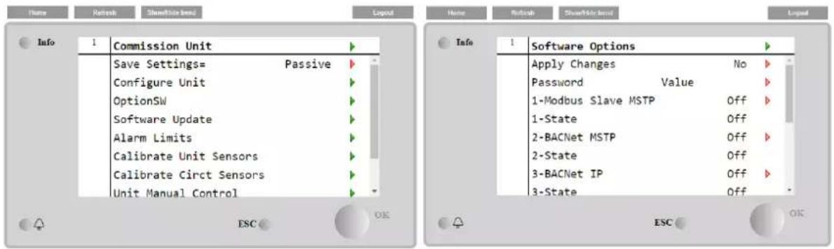
text_image
Name Refresh Show/Share bond Logoul Info 1 Commission Unit Save Settings= Passive Configure Unit OptionSW Software Update Alarm Limits Calibrate Unit Sensors Calibrate Circt Sensors Unit Manual Control ESC OK Home Refresh Show/Share bond Logoul Info 1 Software Options Apply Changes No Password Value 1-Modbus Slave MSTP Off 1-State Off 2-BACNet MSTP Off 2-State Off 3-BACNet IP Off 3-State Off ESC OK| Parameter | Description |
| Password | Writable by Interface/Web Interface |
| Option Name | Option Name |
| Option Status | Option is activated.Option is not activated |
The Current Password inserted activates the selected options.
4.2.13.1 Changing the Password for buying new Software Options
The Option Set and the Password are updated in the Factory. If the customer wants to change its Option Set, he needs to contact the Daikin Personnel and asks for a new password.
As soon as the new password is communicated, the follow steps allow the customer to change the Option Set by himself:
- Wait for the circuits are both OFF, then, from the Main Page, Main Menu→Unit Enable→Unit→Disable
- Go to Main Menu→Commission Unit→Configuration→Software Options
- Select the Options to Activate
- Insert the Password
- Wait for the States of the selected options going to On
- Apply Changes→Yes (it will reboot the controller)
The Password is changeable only if the machine is working in safe conditions: both the circuits are in the State Off.
4.2.13.2 Inserting the Password in a Spare Controller
If the Controller is broken and/or it needs to be replaced for any reason, the customer needs to configure the Option Set with a new Password.
If this replacement is scheduled, the customer can ask to Daikin Personnel for a new Password and repeat the steps in chapter 4.4.1.
If there is no enough time to ask for a Password to Daikin Personnel (ex. an expected failure of the controller), a set of Free Limited Password is provided, in order not to interrupt the machine's working.
These Passwords are free and visualized in:
Main Menu→Commission Unit→Configuration→Software Options→Temporary Passwords
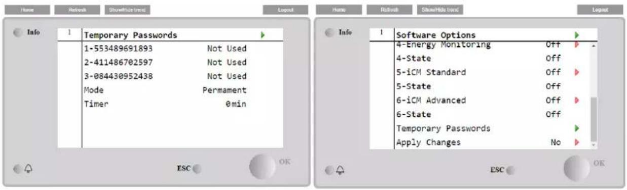
text_image
Info 1 Temporary Passwords 1-553489691893 Not Used 2-411486702597 Not Used 3-084430952438 Not Used Mode Permanent Timer 0min ESC OK Info 1 Software Options 4-Energy Monitoring Off 4-State Off 5-iCM Standard Off 5-State Off 6-iCM Advanced Off 6-State Off Temporary Passwords Apply Changes No ESC OKTheir Use is limited up to three months:
• 553489691893 –3 Months Duration
• 411486702597 -1 Month Duration
• 084430952438 – 1 Month Duration
| Parameter | Specific Status | Description |
| 553489691893 | Activate the Option Set for 3 Months. | |
| 411486702597 | Activate the Option Set for 1 Month. | |
| 084430952438 | Activate the Option Set for 1 Month. | |
| Mode | Permanent | A permanent Password is inserted. Option set can be used for unlimited time. |
| Temporary | A temporary Password is inserted. Option set can be used depending on the password inserted. | |
| Timer | Last duration of the Option Set activated. Enabled only if the mode is Temporary |
The Password is changeable only if the machine is working in safe conditions: both the circuits are in the State Off
4.2.13.3 Modbus MSTP Software Option
When the software option "Modbus MSTP" is activated and the controller is restarted, the communication protocol settings page can be accessed via the path:
Main Menu→Commission Unit→SW Modbus MSTP
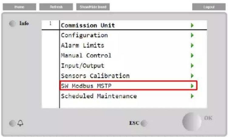
text_image
Home Refresh ShowHide Trend Layout Info 1 Commission Unit Configuration Alarm Limits Manual Control Input/Output Sensors Calibration SW Modbus MSTP Scheduled MaintenanceThe values that can be set are the same as those found on the Modbus MSTP option page with the relative driver, and depend on the specific system where the unit is installed.
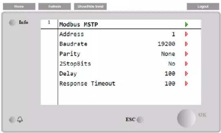
text_image
Home Refresh Show/Hide trend Logout Info 1 Modbus MSTP Address 1 Baudrate 19200 Parity None 2StopBits No Delay 100 Response Timeout 100 ESC OK
To establish the connection, the RS485 port to use is the one on the T14 terminal of the MT4 controller.

4.2.13.4 BACNET MSTP
When the software option "BACNet MSTP" is activated and the controller is restarted, the communication protocol settings page can be accessed via the path:
Main Menu→Commission Unit→SW BACNet MSTP
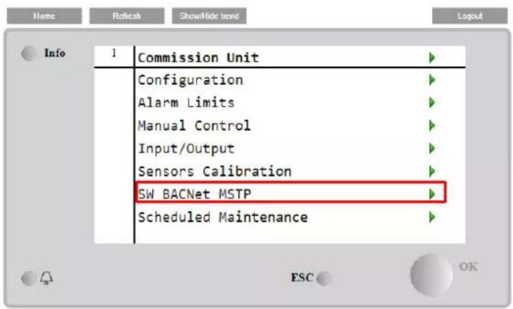
text_image
Home Refresh Show/Hide Trend Logout Info 1 Commission Unit Configuration Alarm Limits Manual Control Input/Output Sensors Calibration SW BACNet MSTP Scheduled MaintenanceThe values that can be set are the same as those found on the BACNet MSTP option page with the relative driver, and depend on the specific system where the unit is installed.

text_image
Info 1 BACNet MSTP Device Instance 1 Name Value Status NoActivePo Address 0 Baudrate 38400 Max Master 1 Max Info Frame 1 Unit System 0 ESC OK
To establish the connection, the RS485 port to use is the one on the T14 terminal of the MT4 controller.

4.2.13.5 BACNET IP
When the software option "BACNet IP" is activated and the controller is restarted, the communication protocol settings page can be accessed via the path:
Main Menu→Commission Unit→SW BACNet IP
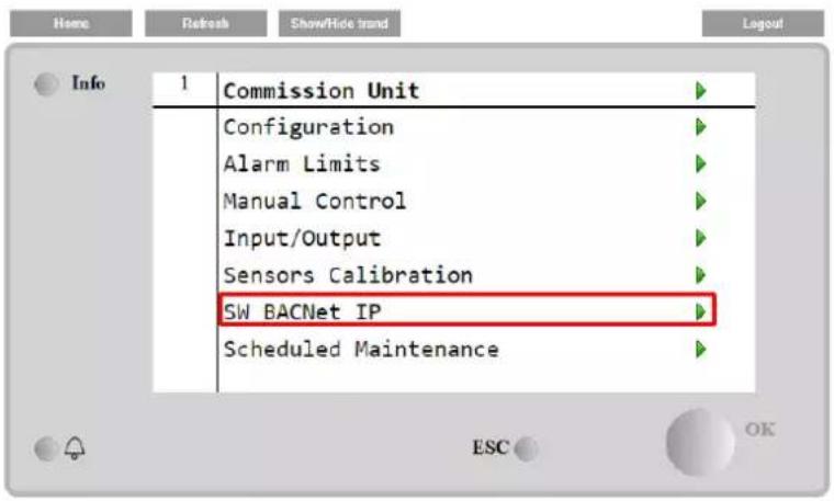
text_image
Home Refresh Show/Ride trend Layout Info 1 Commission Unit Configuration Alarm Limits Manual Control Input/Output Sensors Calibration SW BACNet IP Scheduled MaintenanceThe values that can be set are the same as those found on the BACNet MSTP option page with the relative driver, and depend on the specific system where the unit is installed.
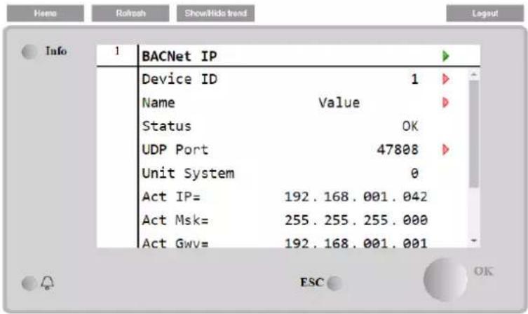
text_image
Info 1 BACNet IP Device ID 1 Name Value Status OK UDP Port 47808 Unit System 0 Act IP= 192.168.001.042 Act Msk= 255.255.255.000 Act GwV= 192.168.001.001 ESC OKThe port for LAN connection to be used for BACNet IP communication is the T-IP Ethernet port, the same one used for remote control of the controller on the PC.
4.2.14 Menu Password
It is possible to keep the User level always active to avoid to enter the User password. To do this the Password Disable setpoint shall be set to On.
| Setpoint/Sub-Menu | Default | Range | Description |
| Pwd Disable | Off | Off, On | Menu for Circuit #1 |
4.3 Active Setpoint
This link jumps to the page "Tmp Setpoint". This page resumes all chiller water temperature setpoints (limits and active setpoint will depend on the operating mode selected).
| Setpoint/Sub-Menu | Default | Range | Description |
| Cool LWT 1= | 7.0°C | 4.0...15.0°C (cool mode)-8.0...15.0°C (cool w/ glycol mode) | Primary cooling setpoint |
| Cool LWT 2= | 7.0°C | 4.0...15.0°C (cool mode)-8.0...15.0°C (cool w/ glycol mode) | Secondary cooling setpoint (see 3.6.3) |
| Heat LWT 1= | 35.0°C | Compressor dependent | Primary Heating setpoint |
| Heat LWT 2= | 35.0°C | Compressor dependent | Secondary Heating setpoint |
| Max LWT= | 15.0°C | 10.0...20.0°C | High limit for Cool LWT1 and Cool LWT2 |
| Min LWT= | -8.0°C | -15.0...-8.0°C | Low limit for Cool LWT1 and Cool LWT2 |
4.4 Evaporator LWT
This link jumps to the page "Temperatures". This page resumes all the relevant water temperatures.
| Setpoint/Sub-Menu | Default | Range | Description |
| Evap LWT= | -273.1°C | - | Controlled water temperature |
| Evap EWT= | -273.1°C | - | Return water temperature |
| Cond LWT= | -273.1°C | - | Condenser leaving water temperature |
| Cond EWT= | -273.1°C | - | Condenser entering water temperature |
| Evap Delta T= | -273.1°C | - | Delta T across Evaporator |
| Cond Delta T= | -273.1°C | - | Delta T across Condenser |
| Pulldn Rate | N/A | - | Rate of decrease of the controlled temperature |
| Ev LWT Slope | 0.0°C/min | - | Rate of decrease of the controlled temperature |
| Cd LWT Slope | 0.0°C/min | - | Rate of decrease of the condenser leaving water temperature |
| Act Slope Lim. | 1.7 °C/min | Maximum slopes | |
| Common LWT= | -273.1°C | - | Master Slave Common supply water temperature |
4.5 Condenser LWT
This link jumps to the page "Temperatures". See section 4.4 for detailed page content.
4.6 Unit Capacity
This page displays the actual unit and circuit capacity
| Setpoint/Sub-Menu | Default | Range | Description |
| Unit= | - | - | Actual unit capacity |
| Circuit #1= | - | - | Actual circuit 1 capacity |
| Circuit #2= | - | - | Actual circuit 2 capacity |
4.7 Unit Mode
This item shows the present Operating Mode and jumps to the page for unit mode selection.
| Setpoint/Sub-Menu | Default | Description | |
| Available Modes= | Cool | Cool, Cool w/ Glycol, Heat/Cool, Heat/Cool w/Glycol, Pursuit, Test | Available operating modes |
Depending on selected mode among availables, the Unit Mode on the main menu will assume the corresponding value according to the following table:
| Available mode selected | ||
| C/H Switch = Cool | C/H Switch = Heat | |
| Cool | Cool | N/A |
| Cool w/ Glycol | ||
| Cool/Ice w/ Glycol | ||
| Ice w/ Glycol | Ice | |
| Heat/Cool | Cool | Heat |
| Heat/Cool w/Glycol | ||
| Heat/Ice w/Glycol | Ice | |
| Pursuit | Pursuit | |
| Test | Test | |
4.8 Unit Enable
This page allows to enable or disable unit and circuits. For the unit it also possible enable the operation with time scheduler, while for circuit it is possible to enable the test mode.
| Setpoint/Sub-Menu | Default | Range | Description |
| Unit | Enable | Enable, Disable, Scheduler | Unit enable command |
| Compressor #1 | Enable | Enable, Disable, Test | Compressor #1 enable command |
| Compressor #2 | Enable | Enable, Disable, Test | Compressor #2 enable command |
| Compressor #3 | Enable | Enable, Disable, Test | Compressor #3 enable command |
4.9 Timers
This page indicates the remaining cycle timers for each circuit and the remaining staging timers. When the cycle timers are active any new start of a compressor is inhibited.
| Setpoint/Sub-Menu | Default | Range | Description |
| C1 Cycle Tm Left= | 0s | - | Compressor 1 cycle timer |
| C2 Cycle Tm Left= | 0s | - | Compressor 2 cycle timer |
| C3 Cycle Tm Left= | 0s | - | Compressor 3 cycle timer |
| C1 Cycle Tmr Clr= | Off | Off, On | Clear compressor 1 cycle timer |
| C2 Cycle Tmr Clr= | Off | Off, On | Clear compressor 2 cycle timer |
| C3 Cycle Tmr Clr= | Off | Off, On | Clear compressor 3 cycle timer |
| Stg Up Dly Rem= | 0s | - | Remaining delay to next compressor start |
| Stg Dn Dly Rem= | 0s | - | Remaining delay to next compressor stop |
| Clr Stg Delays= | Off | Off, On | Clear remaining delays to next compressor start/stop |
4.10 Alarms
This link jumps to the same page accessible with the Bell button. Each of the items represents a link to a page with different information. The information shown depends on the abnormal operating condition that caused the activation of unit, circuit or compressor safeties. A detailed description of the alarms and how to handle will be discussed in the section 6.
| Setpoint/Sub-Menu | Default | Description |
| Alarm Active | ▶ | List of the active alarms |
| Alarm Log | ▶ | History of all the alarms and acknowledges |
| Event Log | ▶ | List of the events |
| Alarm Snapshot | ▶ | List of alarm snapshots with all the relevant data recorded at time the alarm occurred. |
4.11 Commission Unit
| Setpoint/Sub-Menu | Default | Range | Description |
| Alarms Limits | ▶ | - | Submenu for alarm limits definition |
| Calibrate Sensors | ▶ | - | Submenus for Unit and Circuit sensor calibration |
| Manual Control | ▶ | - | Submenus for Unit and Circuit manual control |
| Scheduled Maintenance | ▶ | - | Submenu for scheduled maintenance |
4.11.1 Alarm Limits
This page contains all alarm limits, including low pressure alarm prevention thresholds. In order to ensure proper operation they have to be set manually according to the specific application.
| Setpoint/Sub-Menu | Default | Range | Description |
| Low Press Hold= | 200.0kPa | 170.0...310.0 kPa | Low pressure safety limit to stop capacity increase (R134a) |
| Low Press Unld= | 190.0kPa | 170.0...250.0 kPa | Low pressure alarm prevention (R134a) |
| Low Press Hold= | 122.0kPa | -27.0...204.0 kPa | Low pressure safety limit to stop capacity increase (VZ with R1234ze) |
| Low Press Unld= | 114.0kPa | -27.0...159.0 kPa | Low pressure alarm prevention (VZ with R1234ze) |
| Low Press Hold= | NA | -27.0... 310.0 | Low pressure safety limit to stop capacity increase (TZ with R1234ze) |
| Low Press Unld= | NA | -27.0... 310.0 | Low pressure alarm prevention (TZ with R1234ze) |
| Hi Cond Pr Dly= | 5s | Delay on the High pressure alarm from transducer | |
| Evap Water Frz | 2.2°C | 2.0...6.0°C | Evaporator Water Freeze Limit |
| Cond Water Frz | 2.2°C | 2.0...6.0°C | Condenser Water Freeze Limit |
| Water Flw Proof= | 15s | 5...15s | Flow proof delay |
| Water Rec Timeout= | 3min | 1...10min | Recirculating timeout before the alarm is raised |
| Low DSH Limit= | 12.0°C | Minimum acceptable discharge superheat |
4.11.2 Calibrate Sensors
| Setpoint/Sub-Menu | Default | Range | Description |
| Unit | ▶ | - | Submenu for Unit calibrate sensor |
| Circuit #1 | ▶ | - | Submenu for Circuit 1 calibrate sensor |
| Circuit #2 | ▶ | - | Submenu for Circuit 2 calibrate sensor |
4.11.2.1 Unit Calibrate Sensors
This page allows a proper calibration of the unit sensors
| Setpoint/Sub-Menu | Default | Range | Description |
| Evap LWT= | 7.0°C | Evaporator LWT current reading (includes the offset) | |
| Evp LWT Offset= | 0.0°C | Evaporator LWT calibration | |
| Evap EWT= | 12.0°C | Evaporator EWT current reading (includes the offset) | |
| Evp EWT Offset= | 0.0°C | Evaporator EWT calibration | |
| Evap Pressure= | Evaporator Refrigerant Pressure | ||
| Evp Pr Offset= | 0.0kPa | Evaporator Refrigerant Pressure Offset | |
| Cond Pressure= | Condenser Refrigerant Pressure | ||
| Cnd Pr Offset= | 0.0kPa | Condenser Refrigerant Pressure Offset | |
| Common LWT | 8°C | Common LWT current reading Includes the offset | |
| Comm LWT Offset= | 0.0°C | Common LWT calibration |
4.11.2.2 Compressor Calibrate Sensors
This page allows to adjust the sensors and transducers readings.
| Setpoint/Sub-Menu | Default | Range | Description |
| Suction Temp= | Suction Temperature current reading (includes the offset) | ||
| Suction Offset= | 0.0°C | Suction Temperature offset | |
| Econ Pressure= | Economizer Pressure current reading (includes the offset) | ||
| Eco Pr Offset= | 0.0kPa | Economizer Pressure offset | |
| Econ Temp= | Economizer Temperature current reading (includes the offset) | ||
| Eco Tmp Offset= | 0.0°C | Economizer Temperature offset |

Calibrations of the Evaporator Pressure and Suction Temperature are mandatory for the applications with negative water temperature setpoints. These calibrations have to be performed with proper gauge and thermometer.
An improper calibration of the two instruments may generate limitation of the operations, alarms and even damages to components.
4.11.3 Scheduled Maintenance
This page may contains the contact number of the Service organization taking care of this unit and the next maintenance visit schedule.
| Setpoint/Sub-Menu | Default | Range | Description |
| Next Maint= | Jan 2015 | Schedule date for next maintenance | |
| Support Reference= | 999-999-999 | Reference number or email of Service Org |
4.12 About this Chiller
This page resumes all the information needed to identify the unit and the current software version installed. These information may be required in case of alarms or unit failure
| Setpoint/Sub-Menu | Default | Range | Description |
| Model | Unit model and code name | ||
| Unit S/N= | Unit serial number | ||
| OV14-00001 | |||
| BSP Ver= | Firmware version | ||
| App Ver= | Software version |
5 WORKING WITH THIS UNIT
This section contains a guide on how to deal with the everyday usage of the unit. Next sections describe how to perform routine tasks on the unit, such as:
- Unit Setup
- Unit/Circuit start-up
- Alarm handling
- BMS Control
- Battery replacement
5.1 Unit Setup
Before starting up the unit, some basic settings need to be set by the customer according to the application.
• Control Source (4.2.2)
• Available Modes (4.7)
• Temperature Settings (5.1.3)
• Alarm Settings (4.11.1)
- Pump Settings (5.1.3.3)
• Power Conservation (4.2.10)
- Date/Time (4.2.8)
- Scheduler (4.2.9)
5.1.1 Control Source
This function allows to select which source should be used for unit control. The following sources are available:
| Local | Unit is enabled by local switches placed into the switchbox, chiller mode (cool, cool w/glycol, ice), LWT setpoint and capacity limit are determined by local settings in the HMI. |
| Network | Unit is enable by a remote switch, chiller mode, LWT setpoint and capacity limit are determined by an external BMS. This function requires:Remote enable connection to a BMS (unit on/off switch must be in remote)Communication module and its connection to a BMS. |
More parameters about network control can be found in 4.2.2.
5.1.2 Available Mode Setting
The following operating modes can be selected through the Available modes menu 4.7:
| Mode | Description | Unit Range |
| Cool | Set if chilled water temperature up to 4°C is required. No glycol is generally needed in the water circuit, unless ambient temperature may reach low values. | A/C and W/C |
| Cool w/Glycol | Set if chilled water temperature below 4°C is required. This operation requires proper glycol/wate mixture in the evaporator water circuit. | A/C and W/C |
| Cool/Ice w/Glycol | Set in case a dual cool/ice mode is required. This setting implies an operation with double setpoint which is activated through a customer supplied switch, according to the following logic:Switch OFF: The chiller will work in cooling mode with the Cool LWT 1 being as the Active SetpointSwitch ON: The chiller will work in ice mode with the Ice LWT as the Active Setpoint. | A/C and W/C |
| Ice w/Glycol | Set if ice storage is required. The application requires the compressors to operate at full load until the ice bank is completed, and then to stop for at least 12 hours. In this mode the compressor(s) will not operate at part load, but will work only in on/off mode. | A/C and W/C |

The following modes allow to switch the unit between heat mode and one of the previous cool mode (Cool, Cool w/Glycol, Ice)
| Heat/Cool | Set in case a dual cool/heat mode is required. This setting implies an operation with double functioning which is activated through the Cool/Heat switch on the electric box:Switch COOL: The chiller will work in cooling mode with the Cool LWT 1 as the Active Setpoint.Switch HEAT: The chiller will work in heat pump mode with the Heat LWT 1 as the Active Setpoint. | W/C |
| Heat/Cool w/Glycol | Set in case a dual cool/heat mode is required. This setting implies an operation with double functioning which is activated through the Cool/Heat switch on the electric box:Switch COOL: The chiller will work in cooling mode with the Cool LWT 1 as the Active Setpoint.Switch HEAT: The chiller will work in heat pump mode with the Heat LWT 1 as the Active Setpoint | W/C |
| Heat/Ice w/Glycol | Set in case a dual cool/heat mode is required. This setting implies an operation with double functioning which is activated through the Cool/Heat switch on the electric box:Switch ICE: The chiller will work in cooling mode with the Ice LWT as the Active Setpoint.Switch HEAT: The chiller will work in heat pump mode with the Heat LWT 1 as the Active Setpoint. | W/C |
| Pursuit | Set in case of double water control cool and contemporary heat. Evaporator leaving water temperature follows the Cool LWT 1 setpoint. Condenser leaving water temperature follows the Heat LWT 1 setpoint. | W/C |
| Mode | Description | Unit Range |
| Test | Enables the Manual Control of the unit. The manual test feature helps in debugging and checking the operational status of sensors and actuators. This feature is accessible only with the maintenance password in the main menu. To activate the test feature is required to disable the Unit from the Q0 switch and change the available mode to Test (see section 5.2.2). | A/C and W/C |
It has to be noted that in case the selected mode cannot be managed by the unit, it will revert to Cool.
5.1.3 Temperature Settings
Purpose of the unit is to keep the evaporator leaving water temperature as close as possible to a pre-set value, called Active Setpoint. The Active Setpoint is calculated by the unit controller based on the following parameters:
• Available Modes
- Double setpoint input
- Scheduler state
- LWT Setpoint
- Setpoint Reset
Operation mode and LWT setpoint can also be set via network if the appropriate control source has been selected.
5.1.3.1 LWT Setpoint Setting
Setpoint range is limited according to the selected operating mode. The controller includes:
- two set points in cooling mode
- two set points in heating mode (W/C units only))
• one set point in ice mode
The above setpoints are activated according to Operating mode, Double Setpoint or Scheduler selection. If the Time Scheduler is enabled the Double Setpoint input state will be ignored by the controller.
The table below lists the LWT Setpoint being activated according to the operation mode, the double setpoint switch status and the scheduler state. The table also reports the defaults and the range allowed for each setpoint.
| Operating Mode | Units | Double Setpoint Input | Scheduler | LWT Setpoint | Default | Range |
| Cool | W/C | OFF | Off, On Setpoint 1 | Cool LWT 1 | 7.0°C | 4.0°C ÷ 15.0°C |
| ON | On Setpoint 2 | Cool LWT 2 | 7.0°C | 4.0°C ÷ 15.0°C | ||
| Heat | W/C | OFF | Off, On Setpoint 1 | Heat LWT 1 | 45.0°C | 30.0°C ÷ 55.0°C(*) |
| ON | On Setpoint 2 | Heat LWT 2 | 45.0°C | 30.0°C ÷ 55.0°C(*) |
The LWT setpoint can be overridden in case the setpoint reset (for details see chapter 5.1.4.3).
5.1.3.2 Thermostat Control Settings
Thermostat control settings, allows to set up the response to temperature variations and the precision of the thermostat control. Default settings are valid for most applications, however site specific conditions may require adjustments in order to have a smooth and precise temperature control or a quicker response of the unit.
The control will start the first circuit if the controlled temperature is higher (Cool Mode) or lower (Heat Mode) than the active setpoint (AS) of at least a Start Up DT (SU) value. Once circuit capacity exceeds the Hi Ld Stg Up % another circuit is switched on. When controlled temperature is within the deadband (DB) error from the active setpoint (AS), unit capacity will not be changed.
If the leaving water temperature decreases below (Cool Mode) or rises above (Heat Mode) the active setpoint (AS), unit capacity is adjusted to keep it stable. A further decreasing (Cool Mode) or increasing (Heat Mode) of the controlled temperature of the Shut Down DT offset (SD) can cause circuit shutdown.
In the Shutdown area the whole unit is switched off. In particular, a compressor will be shut down if it is required to unload below the Lt Ld Stg Dn % capacity.
Loading and unloading speeds are calculated by a proprietary PID algorithm. However, maximum the rate of water temperature decrease can be limited through the parameter Max Pulldn.

Circuits are always started and stopped to guarantee the balancing of running hours and number or starts in multiple circuits units. This strategy optimizes the lifetime of compressors, inverters, capacitors and all the others circuit components.

line
| Phase | Temperature Level | | ----------------- | ----------------- | | AS+S | High | | AS-SD | Low | | COOL MODE | Low |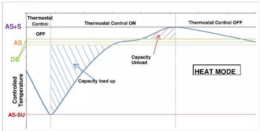
line
| Phase | Temperature Level | | ------------------ | ----------------- | | AS+S | Off | | AS | Off | | DB | Off | | Capacity Unload | Capacity Load Up | | Control Temperature | Controlled Temperature | | AS-SU | - |5.1.3.3 Pumps
The UC can manages one or two water pumps for both evaporator and condenser.
The following options are available to control the pump(s):
1 Only Set to this in case of single pump or twin pump with only #1 operational (f.e. in case of maintenance on #2)
2 Only Set to this in case of twin pump with only #2 operational (f.e. in case of maintenance on #1)
Auto Set for automatic pump start management. At each chiller start, the pump with the least number of hours will be activated.
1 Primary Set to this in case of twin pump with #1 running and #2 as a backup
2 Primary Set to this in case of twin pump with #2 running and #1 as a backup
5.1.4 Power Conservation
Demand limit function allows the unit to be limited to a specified maximum load. Capacity limit level is defined with an external 4-20 mA signal and linear relationship. 4 mA indicate maximum capacity available whereas 20 mA indicates minimum capacity available.
With demand limit function is not possible shutdown the unit but only unload it until minimum admissible capacity. Demand limit related setpoints available through this menu are listed in the table below.
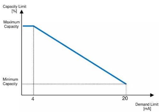
line
| Demand Limit [mA] | Capacity Limit [%] | | ----------------- | ------------------ | | 4 | Maximum Capacity | | 20 | Minimum Capacity || Parameter | Description |
| Unit Capacity | Displays current unit capacity |
| Demand Limit En | Enables demand limit |
| Demand Limit | Displays active demand limit |
5.1.4.2 Current Limit (Optional)
Current limit function allows to control unit power consumption taking current drawn below a specific limit. Starting from the Current Limit Setpoint defined through the HMI or BAS communication, user can change the limit.
5.1.4.3 Setpoint Reset
The setpoint reset function overrides the chilled water temperature selected through the interface, when certain circumstances occur. This feature helps in reducing energy consumption optimizing comfort as well. Three different control strategies can be selected:
- Setpoint Reset by an external signal (4-20mA)
- Setpoint Reset by Evaporator T (Return)
The following setpoints are available through this menu:
| Parameter | Description |
| Setpoint Reset | Set the Setpoint Reset mode (None, 4-20 mA, Return, OAT) |
| Max Reset | Max Setpoint Reset (valid for all active modes) |
| Start Reset DT | Used on Setpoint Reset by Evaporator DT |
5.1.4.4 Setpoint Reset by External 4-20 mA Signal
The active setpoint is calculated applying a correction based on an external 4-20mA signal. 4 mA corresponds to 0°C correction, while 20 mA corresponds to a correction of the active setpoint as set in Max Reset (MR).

line
| Signal | AS | | ------ | ------ | | 0 | LWT SP | | 4mA | LWT SP | | 20mA | LWT SP + MR || Parameter | Default | Range |
| Max Reset (MR) | 5.0°C | 0.0°C ÷ 10.0°C |
| Active Setpoint (AS) | ||
| LWT Setpoint (LWT SP) | Cool/Ice LWT | |
| Signal | 4-20mA External signal |
5.1.4.5 Setpoint Reset by Evaporator Return Temperature
The active setpoint is calculated applying a correction that depends on the evaporator entering (return) water temperature. As evaporator T becomes lower than the SR T value, an offset to the LWT setpoint is increasingly applied, up to the MR value when the return temperature reaches the chilled water temperature.

The Return Reset may affect negatively the chiller operation when operated with variable flow. Avoid to use this strategy in case of inverter water flow control.
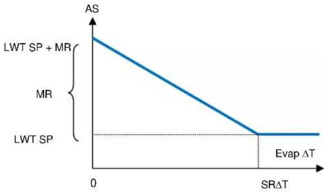
line
| SRΔT | AS | |------|----| | 0 | AS | | >SRΔT | 0 || Parameter | Default | Range |
| Max Reset (MR) | 5.0°C | 0.0°C ÷ 10.0°C |
| Start Reset DT (SRAT) | 5.0°C | 0.0°C ÷ 10.0°C |
| Active Setpoint (AS) | ||
| LWT Target (LWT SP) | Cool/Ice LWT |
5.1.4.6 Soft Load
Soft Loading is a configurable function used to ramp up the unit capacity over a given time period, usually used to influence building electrical demand by gradually loading the unit. The setpoints that control this function are:
| Parameter | Description |
| Softload En | Enables soft loading |
| Softload Ramp | Duration of the soft load ramp |
| Starting Cap | Begin capacity limit. Unit will increase capacity from this value to 100% over the time specified by the Softload Ramp setpoint. |
5.1.5 Date/Time
5.1.5.1 Date, Time and UTC Settings
See 0.
5.1.6 Scheduler
Unit On/Off can be managed automatically through the function Time Scheduler enabled when the parameter Unit Enable is set to Scheduler. For each day of the week user can define six time slots and choose for each time slot one of following mode:
| Parameter | Description |
| Off | Unit Off |
| On Setpoint 1 | Unit On and Cool LWT 1 is the active setpoint |
| On Setpoint 2 | Unit On and Cool LWT 2 is the active setpoint |
5.2 Unit Start-up
In this section, starting and stopping sequence of the unit will be described. status will be briefly described to allow a better understanding of what is going on into the chiller control.
5.2.1 Unit Status
One of the texts strings listed in the table below will inform, on the HMI, about the Unit Status.
| Overall Status | Status text | Description |
| Off: | Keypad Disable | The Unit has been disabled by keypad. Check with your local maintenance if it can be enabled. |
| Loc/Rem Switch | The Local/Remote enable switch is set to disable. Turn it to Local to enable the unit to start its starting sequence. | |
| BAS Disable | Unit is disabled by BAS/BMS system. Check with the BAS company how to start the unit. | |
| Master Disable | Unit is disabled by the Master Slave function | |
| Scheduler Disabled | Unit is disabled by the time scheduler. | |
| Unit Alarm | A unit alarm is active. Check the alarm list to see what is the active alarm inhibiting the unit to start and check if the alarm can be cleared. Refer to section 6. before proceeding. | |
| Test Mode | Unit mode set to Test. This mode is activated to check operability of onboard actuators and sensors. Check with the local maintenance if the Mode can be reverted to the one compatible with unit application (View/Set Unit – Set-Up – Available Modes). | |
| All Cir Disabled | No circuit is available to run. All circuits can be disabled by their individual enable switch or can be disabled by a component safety condition active or can be disabled by keypad or can be all in alarms. Check the individual circuit status for further details. | |
| Ice Mode Tmr | This status can be shown only if the unit can work in Ice Mode. The unit is off because the Ice setpoint has been satisfied. Unit will remain off until the Ice Timer has expired. | |
| OAT Lockout (A/C units only) | The unit cannot run because the Oustide Air Temperature is below the limit foreseen for the condenser temperature control system installed in this Unit. If the Unit has to run anyway check with your local maintenance how to proceed. | |
| Auto | Unit is in Auto control. The pump is running and at least one compressor is running. | |
| Auto: | Evap Recirc | Unit is running the evaporator pump to equalize the water temperature in the evaporator. |
| Wait For Flow | Unit pump is running but the flow signal still indicate a lack of flow through the evaporator. | |
| Wait For Load | Unit is in standby because the thermostat control satisfied the active setpoint. | |
| Unit Cap Limit | Demand limit has been hit. Unit capacity will not further increase. | |
| Current Limit | Maximum current has been hit. Unit capacity will not further increase. | |
| Noise Reduction | Unit is running with the Quiet Mode activated. Active setpoint may differ from what has bee set as cooling setpoint. | |
| Max Pulldn | Unit thermostat control is limiting the unit capacity because the water temperature is dropping at a rate that could exceed the active setpoint. | |
| Pumpdn | Unit is shutting down. |
5.2.2 Prepare the unit to start
The unit starts only if all the enable setpoints/signals are active:
- Unit Switch Enable (signal) = Enable
- Keypad Enable (setpoint) = Enable
• BMS Enable (setpoint) = Enable
5.2.2.1 Unit Switch Enable
Each unit is equipped with a Main selector installed outside the front panel of the unit switchbox. As shown in the pictures below, for VZ units, two different positions can be selected: Local, Disable:
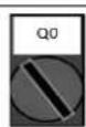
Local With the Q0 switch in this position the unit is enabled. Pump will start if all other enable signals are set to enable and at least one compressor is available to run
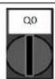
Disable With the Q0 switch in this position the unit is disabled. Pump will not start in normal operational condition. Compressor are kept disabled independently from the status of the individual enable switches.
5.2.3 Keypad Enable
The Keypad enable setpoint is not accessible by user password level. If it is set to "Disable", contact your local maintenance service to check if it can be changed to Enable.
5.2.3.1 BMS Enable
The last enable signal is coming through the high level interface, that is from a Building Management System. The unit can be enabled/disabled from a BMS connected to the UC using a communication protocol. In order to control the unit over the network, the Control Source setpoint must be turned in "Network" (default is Local) and Network En Sp must be "Enable" (4.2.2). If disabled, check with your BAS company how the chiller is operated.
5.3 Condensation Control
Condenser Entering Water Temperature is controlled in order to achieve best chiller efficiency within compressor envelope limits. To do this, application manages the outputs for the control of the following condensation devices:
- Tower fan #1...4 by mean of 4 on/off signals. Tower fan # state is on when Cond EWT is greater than the Cond EWT setpoint. Tower fan # state is off when Cond EWT is lower than Setpoint – Diff. The picture below represents an example of activation and deactivation sequence based on Cond EWT present value relation with set points and differentials listed in 4.2.4.
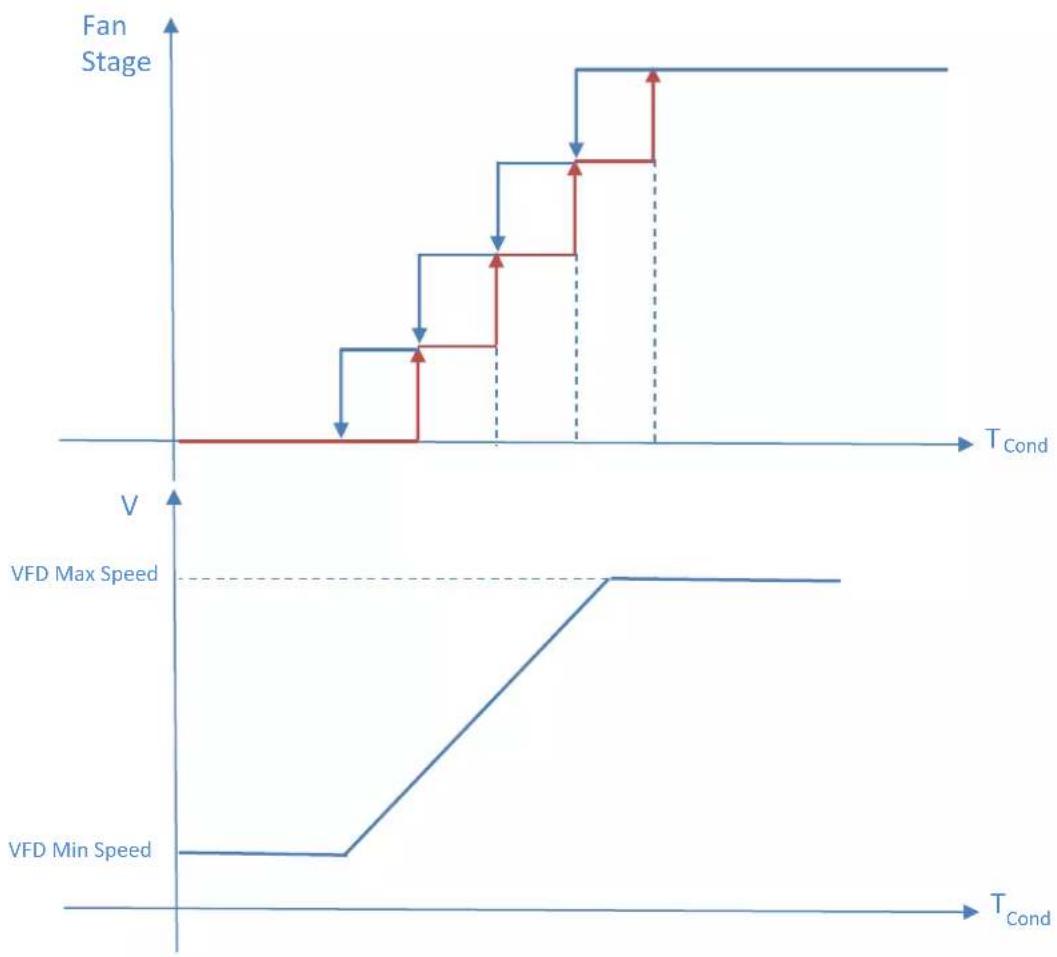
line
| TCond | Fan Stage | VFD Max Speed | VFD Min Speed | |-------|-----------|---------------|---------------| | Low | 0 | 0 | 0 | | Mid | Decreasing | 0 | 0 | | High | Stable | Maximum | Maximum |- 1 Vfd by mean of a modulating 0-10V signal generated through a PID controller. The following graph is an example of the modulating signal behavior in case of a PID control supposed to be purely proportional.
6 ALARMS AND TROUBLESHOOTING
The UC protects the unit and the components from operating in abnormal conditions. Protections can be divided in preventions and alarms. Alarms can then be divided in pump-down and rapid stop alarms. Pump-down alarms are activated when the system or sub-system can perform a normal shutdown in spite of the abnormal running conditions. Rapid stop alarms are activated when the abnormal running conditions require an immediate stop of the whole system or sub-system to prevent potential damages.
The UC displays the active alarms in a dedicated page and keep an history of the last 50 entries divided between alarms and acknowledges occurred. Time and date for each alarm event and of each alarm acknowledge are stored.
The UC also stores alarm snapshot of each alarm occurred. Each item contains a snapshot of the running conditions right before the alarm has occurred. Different sets of snapshots are programmed corresponding to unit alarms and circuit alarms holding different information to help the failure diagnosis.
In the following sections it will also be indicated how each alarm can be cleared between local HMI, Network (by any of the high level interfaces Modbus, Bacnet or Lon) or if the specific alarm will clear automatically. The following symbols are used:
| ☑ | Allowed |
| ☒ | Not allowed |
| ☐ | Not foreseen |
6.1 Unit Alerts
6.1.1 Bad Demand Limit Input
This alarm is generated when the Demand Limit option has been enabled and the input to the controller is out of the admitted range.
| Symptom | Cause | Solution |
| Unit status is Run.Bell icon is moving on controller's display.Demand Limit function cannot be used.String in the alarm list:BadDemandLimitInputString in the alarm log:±BadDemandLimitInputString in the alarm snapshotBadDemandLimitInput | Demand limit input out of range.For this warning out of range is considered to be a signal less than 3mA or more than 21mA. | Check for values of input signal to the unit controller. It has to be in the allowed mA range. |
| Check for electrical shielding of wirings. | ||
| Check for right value of the unit's controller output in case input signal is into allowed range. | ||
| Reset | Notes | |
| Local HMINetworkAuto | ☐☐☑ | Automatically clears when the signal returns in the allowed range. |
6.1.2 Bad Leaving Water Temperature Reset Input
This alarm is generated when the Setpoint Reset option has been enabled and the input to the controller is out of the admitted range.
| Symptom | Cause | Solution |
| Unit status is Run.Bell icon is moving on controller's display.LWT Reset function cannot be used.String in the alarm list:BadSetPtOverrideInputString in the alarm log:± BadSetPtOverrideInputString in the alarm snapshotBadSetPtOverrideInput | LWT reset input signal is out of range.For this warning out of range is considered to be a signal less than 3mA or more than 21mA. | Check for values of input signal to the unit controller. It has to be in the allowed mA range. |
| Check for electrical shielding of wirings. | ||
| Check for right value of the unit's controller output in case input signal is into allowed range. | ||
| Reset | Notes | |
| Local HMINetworkAuto | ☐☐☑ | Automatically clears when the signal returns in the allowed range. |
6.1.3 Condenser Pump #1 Failure (W/C units only)
This alarm is generated if the pump is started but the flow switch is not able to close within the recirculate time. This can be a temporary condition or may be due to a broken flowswitch, the activation of circuit breakers, fuses or to a pump breakdown.
| Symptom | Cause | Solution |
| Unit could be ON.Bell icon is moving on controller's display.Backup pump is used or stop of all circuits in case of pump #2 failure.String in the alarm list:CondPump1FaultString in the alarm log:± CondPump1FaultString in the alarm snapshotCondPump1Fault | Pump #1 may not be operating. | Check for problem in electrical wiring of the pump #1. |
| Check that electrical breaker of pump #1 is tripped. | ||
| If fuses are used to protect the pump, check the integrity of fuses. | ||
| Check for problem in wiring connection between pump starter and unit controller. | ||
| Check the water pump filter and the water circuit for obstructions. | ||
| Flow Switch doesn't operate properly | Check flow switch connection and calibration. | |
| Reset | Notes | |
| Local HMINetworkAuto | ☑☑☐ |
6.1.4 Condenser Pump #2 Failure (W/C units only)
This alarm is generated if the pump is started but the flow switch is not able to close within the recirculate time. This can be a temporary condition or may be due to a broken flowswitch, the activation of circuit breakers, fuses or to a pump breakdown.
| Symptom | Cause | Solution |
| Unit could be ON.Bell icon is moving on controller's display.Backup pump is used or stop of all circuits in case of pump #1 failure.String in the alarm list:CondPump2FaultString in the alarm log:± CondPump2FaultString in the alarm snapshotCondPump2Fault | Pump #1 may not be operating. | Check for problem in electrical wiring of the pump #1. |
| Check that electrical breaker of pump #1 is tripped. | ||
| If fuses are used to protect the pump, check the integrity of fuses. | ||
| Check for problem in wiring connection between pump starter and unit controller. | ||
| Check the water pump filter and the water circuit for obstructions. | ||
| Flow Switch doesn't operate properly | Check flow switch connection and calibration. | |
| Reset | Notes | |
| Local HMINetworkAuto | ☑☑☐ |
6.1.5 Evaporator Pump #1 Failure
This alarm is generated if the pump is started but the flow switch is not able to close within the recirculate time. This can be a temporary condition or may be due to a broken flowswitch, the activation of circuit breakers, fuses or to a pump breakdown.
| Symptom | Cause | Solution |
| Unit could be ON.Bell icon is moving on controller's display.Backup pump is used or stop of all circuits in case of pump #2 failure.String in the alarm list:EvapPump1FaultString in the alarm log:± EvapPump1FaultString in the alarm snapshotEvapPump1Fault | Pump #1 may not be operating. | Check for problem in electrical wiring of the pump #1. |
| Check that electrical breaker of pump #1 is tripped. | ||
| If fuses are used to protect the pump, check the integrity of fuses. | ||
| Check for problem in wiring connection between pump starter and unit controller. | ||
| Check the water pump filter and the water circuit for obstructions. | ||
| Flow Switch doesn't operate properly | Check flow switch connection and calibration. | |
| Reset | Notes | |
| Local HMINetworkAuto | ☑☑☐ |
6.1.6 Evaporator Pump #2 Failure
This alarm is generated if the pump is started but the flow switch is not able to close within the recirculate time. This can be a temporary condition or may be due to a broken flowswitch, the activation of circuit breakers, fuses or to a pump breakdown.
| Symptom | Cause | Solution |
| Unit could be ON.Bell icon is moving on controller's display.Backup pump is used or stop of all circuits in case of pump #1 failure.String in the alarm list:EvapPump2FaultString in the alarm log:± EvapPump2FaultString in the alarm snapshotEvapPump2Fault | Pump #2 may not be operating. | Check for problem in electrical wiring of the pump #2. |
| Check that electrical breaker of pump #2 is tripped. | ||
| If fuses are used to protect the pump, check the integrity of fuses. | ||
| Check for problem in wiring connection between pump starter and unit controller. | ||
| Check the water pump filter and the water circuit for obstructions. | ||
| Flow Switch doesn't operate properly | Check flow switch connection and calibration. | |
| Reset | Notes | |
| Local HMINetworkAuto | ☑☑☐ |
6.1.7 External Event
This alarm indicates that a device, whose operation is linked with this machine, is reporting a problem on the dedicated input.
| Symptom | Cause | Solution |
| Unit status is Run.Bell icon is moving on controller's display.String in the alarm list:UnitExternalEventString in the alarm log:± UnitExternalEventString in the alarm snapshotUnitExternalEvent | There is an external event that has caused the opening, for at least 5 seconds, of the digital input on the controller board. | Check for reasons of external event and if it can be a potential problem for a correct chiller operation. |
| Reset | Notes | |
| Local HMINetworkAuto | ☐☐☑ | The alarm is automatically cleared when the problem is solved. |
| NOTE: What above applies in case of configuration of the external fault digital input as Event | ||
6.1.8 Password Over Time
This alarm indicates that a device, whose operation is linked with this machine, is reporting a problem on the dedicated input.
| Symptom | Cause | Solution |
| Pass1TimeOver 1dayleft | Temporary Password Inserted is going to expire. One day is left before Option set is unactivated. | A Permanent Password must be inserted in order to keep on using selected software option set. Refer to Chapter "Software Options". |
| Pass1TimeOver 1dayleft | ||
| Pass1TimeOver 1dayleft | ||
| Reset | ||
| Local HMI | ☑ | |
| Network | ☐ | |
| Auto | ☐ |
6.2 Unit Pumpdown Stop Alarms
Condenser Entering Water Temperature (EWT) sensor fault
This alarm is generated any time the input resistance is out of an acceptable range.
| Symptom | Cause | Solution |
| Unit status is Off. | Sensor is broken. | Check for sensor integrity according table and allowed kOhm (kΩ) range. |
| All circuits are stopped with a normal shutdown procedure. | Check correct sensors operation | |
| Bell icon is moving on controller's display. | ||
| String in the alarm list: | Sensor is shorted. | Check if sensor is shorted with a resistance measurement. |
| UnitOffCndEntWTempSen | ||
| String in the alarm log: | Sensor is not properly connected (open). | Check for absence of water or humidity on electrical contacts. |
| ± UnitOffCndEntWTempSen | Check for correct plug-in of the electrical connectors. | |
| String in the alarm snapshot | Check for correct sensors wiring also according electrical scheme. | |
| UnitOffcndEntWTempSen | ||
| Reset | Notes | |
| Local HMI | ☑ | |
| Network | ☑ | |
| Auto | ☐ |
Condenser Leaving Water Temperature (LWT) sensor fault
This alarm is generated any time the input resistance is out of an acceptable range.
| Symptom | Cause | Solution |
| Unit status is Off. | Sensor is broken. | Check for sensor integrity according table and allowed kOhm (kΩ) range. |
| All circuits are stopped with a normal shutdown procedure. | Check correct sensors operation | |
| Bell icon is moving on controller's display. | ||
| String in the alarm list: | Sensor is shorted. | Check if sensor is shorted with a resistance measurement. |
| UnitOffCndLvgWTempSen | ||
| String in the alarm log: | Sensor is not properly connected (open). | Check for absence of water or humidity on electrical contacts. |
| ± UnitOffCndLvgWTempSen | Check for correct plug-in of the electrical connectors. | |
| String in the alarm snapshot | Check for correct sensors wiring also according electrical scheme. | |
| UnitOffcndLvgWTempSen | ||
| Reset | Notes | |
| Local HMI | ☑ | |
| Network | ☑ | |
| Auto | ☐ |
Evaporator Entering Water Temperature (EWT) sensor fault
This alarm is generated any time the input resistance is out of an acceptable range.
| Symptom | Cause | Solution |
| Unit status is Off. | Sensor is broken. | Check for sensor integrity according table and allowed kOhm (kΩ) range. |
| All circuits are stopped with a normal shutdown procedure. | Check correct sensors operation | |
| Bell icon is moving on controller's display. | ||
| String in the alarm list: | Sensor is shorted. | Check if sensor is shorted with a resistance measurement. |
| UnitOffEvpEntWTempSen | ||
| String in the alarm log: | Sensor is not properly connected (open). | Check for absence of water or humidity on electrical contacts. |
| ± UnitOffEvpEntWTempSen | Check for correct plug-in of the electrical connectors. | |
| String in the alarm snapshot | Check for correct sensors wiring also according electrical scheme. | |
| UnitOffEvpEntWTempSen | ||
| Reset | Notes | |
| Local HMI | ☑ | |
| Network | ☑ |
6.2.4 Evaporator Water Temperatures inverted
This alarm is generated any time the entering water temperature is lower than the leaving by 1^ C and at least one compressor is running since 90 seconds.
| Symptom | Cause | Solution |
| Unit status is Off.All circuits are stopped with a normal shutdown procedure.Bell icon is moving on controller's display.String in the alarm list:UnitOffEvpWTempInvrtdString in the alarm log:± UnitOffEvpWTempInvrtdString in the alarm snapshotUnitOffEvpWTempInvrtd | Entering and leaving water temperature sensors are inverted. | Check cabling of the sensors on the unit controller. |
| Check offset of the two sensors with the water pump running | ||
| Entering and leaving water pipes are reversed | Check if the water flows in counter flow respect to refrigerant. | |
| Water pump operate reverse. | Check if the water flows in counter flow respect to refrigerant. | |
| Reset | Notes | |
| Local HMINetworkAuto | ☑☑☐ |
6.2.5 Liquid Temperature Sensor fault
This alarm is generated to indicate that the sensor is not reading properly.
| Symptom | Cause | Solution |
| Circuit status is Off.The circuit is switched off with the normal shutdown procedure.Bell icon is moving on controller's display.String in the alarm list:UnitOffLiquidTempSenString in the alarm log:± UnitOffLiquidTempSenString in the alarm snapshotUnitOffLiquidTempSen | Sensor is shorted. | Check for sensor integrity. |
| Check correct sensors operation according information about kOhm (kΩ) range related to temperature values. | ||
| Sensor is broken. | Check if sensor is shorted with a resistance measurement. | |
| Sensor is not properly connected (open). | Check for correct installation of the sensor on refrigerant circuit pipe. | |
| Check for absence of water or humidity on sensor electrical contacts. | ||
| Check for correct plug-in of the electrical connectors. | ||
| Check for correct sensors wiring also according with electrical scheme. | ||
| Reset | Notes | |
| Local HMINetworkAuto | ☑☑☐ |
6.3 Unit Rapid Stop Alarms
6.3.1 PVM alarm (A/C units only)
This alarm is generated in case of problems with the power supply to the chiller.

Resolution of this fault requires a direct intervention on the power supply of this unit. Direct intervention on the power supply can cause electrocution, burns or even death. This action must be performed only by trained persons. In case of doubts contact your maintenance company.
| Symptom | Cause | Solution |
| Unit status is Off.All circuits are stopped immediately. Bell icon is moving on controller's display.String in the alarm list:UnitOffPhaveVoltageString in the alarm log:± UnitOffPhaveVoltageString in the alarm snapshotUnitOffPhaveVoltage | Loss of one phase. | Check voltage level on each of the phases |
| Not correct sequence connection of L1,L2,L3. | Check sequence of L1, L2, L3 connections according indication on chiller's electrical scheme. | |
| Voltage level on the unit's panel is not in the allowed range (±10%). | Check that voltage level on each phases is into the allowed range that is indicated on the chiller label.Is important to check the voltage level on each phases not only with chiller not running, but mainly with chiller running from minimum capacity up to full load capacity. That's because voltage drop can occur from a certain unit cooling capacity level, or because of certain working condition (i.e. high values of OAT).In these cases the issue can be related with the sizing of power cables. | |
| There is a short-circuit on the unit. | Check for correct electrical isolation condition of each unit's circuit with a Megger tester. | |
| Reset | Notes | |
| Local HMINetworkAuto | ☐☐☑ |
6.3.2 Condenser Water Freeze alarm (W/C units only)
This alarm is generated to indicate that the water temperature (entering or leaving) has dropped below a safety limit. Control tries to protect the heat exchanger starting the pump and letting the water circulate.
| Symptom | Cause | Solution |
| Unit status is Off.All circuits are stopped immediately.Bell icon is moving on controller's display.String in the alarm list:UnitOffCondWaterTmpLoString in the alarm log:± UnitOffCondWaterTmpLoString in the alarm snapshotUnitOffCondWaterTmpLo | Water flow too low. | Increase the water flow. |
| Inlet temperature to the evaporator is too low. | Increase the inlet water temperature. | |
| Flow switch is not working or no water flow. | Check the flow switch and the water pump. | |
| Refrigerant temperature become too low (< -0.6°C). | Check the water flow and filter. No good heat exchange condition into the evaporator. | |
| Sensors readings (entering or leaving) are not properly calibrated | Check the water temperatures with a proper instrument and adjust the offsets | |
| Wrong freeze limit setpoint | The freeze limit has not been changed as a function of glycol percentage. | |
| Reset | Notes | |
| Local HMINetworkAuto | ☑☒☐ | It's required to check if the condenser has any damage due to this alarm. |
6.3.3 Condenser Water Flow Loss alarm (W/C units only)
This alarm is generated in case of flow loss to the chiller to protect the machine against Mechanical High Pressure trips.
| Symptom | Cause | Solution |
| Unit status is Off.All circuits are stopped immediately.Bell icon is moving on controller's display.String in the alarm list:UnitOffCondWaterFlowString in the alarm log:± UnitOffCondWaterFlowString in the alarm snapshotUnitOffCondWaterFlow | No water flow sensed for 3 minutes continuously or water flow too low. | Check the water pump filler and the water circuit for obstructions. |
| Check the flow switch calibration and adapt to minimum water flow. | ||
| Check if pump impeller can rotate freely and has no damages. | ||
| Check pumps protection devices (circuit breakers, fuses, inverters, etc.) | ||
| Check if water filter is clogged. | ||
| Check flow switch connections. | ||
| Reset | Notes | |
| Local HMI | ☑ | |
| Network | ☑ | |
| Auto | ☐ |
6.3.4 Emergency Stop
This alarm is generated any time the Emergency Stop button is activated.

Before resetting the Emergency Stop button please verify that the harmful condition has been removed.
| Symptom | Cause | Solution |
| Unit status is Off.All circuits are stopped immediately.Bell icon is moving on controller's display.String in the alarm list:UnitOffEmergencyStopString in the alarm log:± UnitOffEmergencyStopString in the alarm snapshotUnitOffEmergencyStop | Emergency stop button has been pushed. | Turning counterclockwise the emergency stop button, the alarm should be cleared. |
| Reset | Notes | |
| Local HMINetworkAuto | ☑☒☐ | Please see note on the top. |
6.3.5 Evaporator Flow Loss alarm
This alarm is generated in case of flow loss to the chiller to protect the machine against freezing.
| Symptom | Cause | Solution |
| Unit status is Off.All circuits are stopped immediately.Bell icon is moving on controller's display.String in the alarm list:UnitOffEvapWaterFlowString in the alarm log:± UnitOffEvapWaterFlowString in the alarm snapshotUnitOffEvapWaterFlow | No water flow sensed for 3 minutes continuously or water flow too low. | Check the water pump filler and the water circuit for obstructions. |
| Check the flow switch calibration and adapt to minimum water flow. | ||
| Check if pump impeller can rotate freely and has no damages. | ||
| Check pumps protection devices (circuit breakers, fuses, inverters, etc.) | ||
| Check if water filter is clogged. | ||
| Check flow switch connections. | ||
| Reset | Notes | |
| Local HMINetworkAuto | ☑☑☐ |
6.3.6 Evaporator Leaving Water Temperature (LWT) sensor fault
This alarm is generated any time that the input resistance is out of an acceptable range.
| Symptom | Cause | Solution |
| Unit status is Off.All circuits are stopped with a normal shutdown procedure.Bell icon is moving on controller's display.String in the alarm list:UnitOffLvgEntWTempSenString in the alarm log:± UnitOffLvgEntWTempSenString in the alarm snapshotUnitOffEvpLvgWTempSen | Sensor is broken. | Check for sensor integrity according table and allowed kOhm (kΩ) range. |
| Check correct sensors operation | ||
| Sensor is shorted. | Check if sensor is shorted with a resistance measurement. | |
| Sensor is not properly connected (open). | Check for absence of water or humidity on electrical contacts. | |
| Check for correct plug-in of the electrical connectors. | ||
| Check for correct sensors wiring also according electrical scheme. | ||
| Reset | Notes | |
| Local HMINetworkAuto | ☑☑☐ |
6.3.7 Evaporator Water Freeze alarm
This alarm is generated to indicate that the water temperature (entering or leaving) has dropped below a safety limit. Control tries to protect the heat exchanger starting the pump and letting the water circulate.
| Symptom | Cause | Solution |
| Unit status is Off.All circuits are stopped immediately.Bell icon is moving on controller's display.String in the alarm list:UnitOffEvapWaterTmpLoString in the alarm log:± UnitOffEvapWaterTmpLoString in the alarm snapshotUnitOffEvapWaterTmpLo | Water flow too low. | Increase the water flow. |
| Inlet temperature to the evaporator is too low. | Increase the inlet water temperature. | |
| Flow switch is not working or no water flow. | Check the flow switch and the water pump. | |
| Sensors readings (entering or leaving) are not properly calibrated. | Check the water temperatures with a proper instrument and adjust the offsets | |
| Wrong freeze limit setpoint. | The freeze limit has not been changed as a function of glycol percentage. | |
| Reset | Notes | |
| Local HMINetworkAuto | ☑☒☐ | It's required to check if the evaporator has any damage due to this alarm. |
6.3.8 External alarm
This alarm is generated to indicate that an external device whose operation is linked with this unit operation. This external device could be a pump or an inverter.
| Symptom | Cause | Solution |
| Unit status is Off.All circuits are switched off with the normal shutdown procedure.Bell icon is moving on controller's display.String in the alarm list:UnitOffExternalAlarmString in the alarm log:± UnitOffExternalAlarmString in the alarm snapshotUnitOffExternalAlarm | There is an external event that has caused the opening, for at least 5 seconds, of the port on the controller board. | Check causes of the external event or alarm. |
| Check electrical wiring from unit controller to the external equipment in case of any external events or alarms have been occurred. | ||
| Reset | Notes | |
| Local HMINetworkAuto | ☑☑☐ | |
| NOTE: What above applies in case of configuration of the external fault digital input as Alarm. | ||
6.3.9 Gas Leakage Alarm
This alarm is generated when the external leak detector(s) detects a refrigerant concentration higher than a threshold. To clear this alarm is required to clear the alarm either locally and, if needed, on the leak detector itself.
| Symptom | Cause | Solution |
| Unit status is Off.All circuits are stopped immediately.Bell icon is moving on controller's display.String in the alarm list:UnitOffGasLeakageString in the alarm log:± UnitOffGasLeakageString in the alarm snapshotUnitOffGasLeakage | Refrigerant leakage | Locate the leakage with a sniffer and fix the leakage |
| Leak detector is not properly powered | Check the power supply of the leak detector. | |
| Leak detector is not properly connected to the controller. | Check the connection of the detector with reference to the wiring diagram of the unit. | |
| Leak detector is broken | Replace the leak detector. | |
| Leak detector is not required/needed | Check the configuration on the unit controller and disable this option. | |
| Reset | Notes | |
| Local HMINetworkAuto | ☑☑☐ |
6.3.10 Power Fault
This alarm is generated when the main power is Off and the unit controller is powered by the UPS.

Resolution of this fault requires a direct intervention on the power supply of this unit. Direct intervention on the power supply can cause electrocution, burns or even death. This action must be performed only by trained persons. In case of doubts contact your maintenance company.
| Symptom | Cause | Solution |
| Unit status is Off.All circuits are stopped immediately. Bell icon is moving on controller's display.String in the alarm list:Power FaultString in the alarm log:± Power FaultString in the alarm snapshotPower Fault | Loss of one phase. | Check voltage level on each of the phases. |
| Not correct sequence connection of L1, L2, L3. | Check sequence of L1, L2, L3 connections according indication on chiller's electrical scheme. | |
| Voltage level on the unit's panel is not in the allowed range (±10%). | Check that voltage level on each phases is into the allowed range that is indicated on the chiller label.Is important to check the voltage level on each phases not only with chiller not running, but mainly with chiller running from minimum capacity up to full load capacity. That's because voltage drop can occur from a certain unit cooling capacity level, or because of certain working condition (i.e. high values of OAT).In these cases the issue can be related with the sizing of power cables. | |
| There is a short-circuit on the unit. | Check for correct electrical isolation condition of each unit's circuit with a Megger tester. | |
| Reset | Notes | |
| Local HMINetworkAuto | ☑☑ |
6.3.11 Low Discharge Superheat
This alarm is generated in case of Low discharge superheat to one of the compressors when the unit is configured with the flash tank economizer. This alarm is activated only for 3-Compressor units.
| Symptom | Cause | Solution |
| Unit status is Off.All circuits are stopped immediately. Bell icon is moving on controller's display.String in the alarm list:UnitOffLowDishShString in the alarm log:± UnitOffLowDishShString in the alarm snapshotUnitOffLowDishSh | Float valve is blocked totally or partially closed. | Try clear the alarm and restart the unit. If the problem persists contact your Daikin Service reference. |
| Reset | Notes | |
| Local HMINetworkAuto | ☑☐☐ |
6.3.12 Mechanical High Pressure Switch Alarm
This alarm is generated when the condenser pressure rises above the mechanical high pressure limit causing this device to open the power supply to all the auxiliary relays. This causes an immediate shutdown of compressor and all the other actuators in this circuit.
| Symptom | Cause | Solution |
| Circuit status is Off.The compressor does not load anymore or even unload, circuit is stopped.Bell icon is moving on controller's display. String in the alarm list:C1 OffMechPressHiString in the alarm log:± C1 OffMechPressHiString in the alarm snapshotC1 OffMechPressHi | Condenser pump may not be operating correctly (W/C units) | Check if the pump can run and give the required water flow. |
| Dirty condenser heat exchanger. | Clean the condenser heat exchanger. | |
| Entering water temperature at condenser is too high. | Check the cooling tower operation and settings. | |
| Check the three way valve operation and settings. | ||
| Mechanical high pressure switch is damaged or not calibrated. | Check for proper operation of the high pressure switch. | |
| Reset | Notes | |
| Local HMINetworkAuto | ☑☒☒ | Reset of this alarm requires a manual action on the high pressure switch. |
6.3.13 High Pressure Alarm
This alarm is generated in case the Condensing saturated temperature rise above the Maximum condensing saturated temperature and the control is not able to compensate to this condition. The maximum condenser saturated temperature depends on compressor model. In case of water cooled chillers operating at high condenser water temperature, if the Condensing saturated temperature exceeds the Maximum condenser saturated temperature, the circuit is only switched off without any notification on the screen as this condition is considered acceptable in this range of operation.
| Symptom | Cause | Solution |
| Circuit status is Off.The compressor does not load anymore or even unload, circuit is stopped.Bell icon is moving on controller's display.String in the alarm list:C1 UnitOffCondPressString in the alarm log:± C1 UnitOffCondPressString in the alarm snapshotC1 UnitOffCondPress | One or more condenser fans do not operate properly (A/C units). | Check if fans protections have been activated. |
| Check that the fans can turn freely. | ||
| Check that there is not any obstacle to the free ejection of the air blown. | ||
| Condenser pump may not be operating correctly (W/C units) | Check if the pump can run and give the required water flow. | |
| Dirty or partially blocked condenser coil (A/C units). | Remove any obstacle;Clean the condenser coil using soft brush and blower. | |
| Dirty condenser heat exchanger (W/C units) | Clean the condenser heat exchanger. | |
| Inlet air temperature of the condenser is too high (A/C units). | The air temperature measured at the inlet of the condenser may not exceed the limit indicated in the operational range (working envelope) of the chiller. | |
| Check the location where the unit is installed and check that there are no any short circuit of the hot-air blown from the fans of the same unit, or even from fans of next chillers (Check IOM for proper installation). | ||
| Entering water temperature at condenser is too high (W/C units). | Check the cooling tower operation and settings. | |
| Check the three way valve operation and settings. | ||
| One or more condenser fan turning in wrong direction (A/C units). | Check for correct phases sequence (L1, L2, L3) in the electrical connection of the fans. | |
| Excessive charge of refrigerant into the unit. | Check liquid sub-cooling and suction super-heat to control indirectly the correct charge of refrigerant. If necessary recover all the refrigerant to weight the entire charge and tocontrol if the value is in line with kg indication on unit label. | |
| Condensing pressure transducer could not operate properly. | Check for proper operation of the high pressure sensor. | |
| Wrong unit configuration (W/C units). | Check that the unit has been configured for high condenser temperature applications. | |
| Reset | Notes | |
| Local HMI Network Auto | ☑ ☑ ☐ |
6.3.14 Low Pressure Alarm
This alarm is generated in case the evaporating pressure drops below the Low Pressure Unload and the control is not able to compensate to this condition.
| Symptom | Cause | Solution |
| Circuit status is Off.The compressor does not load anymore or even unload, circuit is stopped immediately.Bell icon is moving on controller's display.String in the alarm list:C1 UnitOffEvapPressString in the alarm log:± C1 UnitOffEvapPressString in the alarm snapshotC1 UnitOffEvapPress | Transitory condition like a fan staging on cooling tower. | Wait until the condition is recovered by EXV control |
| Refrigerant charge is low. | Check sight glass on liquid line to see if there is flash gas. | |
| Measure sub-cooling to see if the charge is correct. | ||
| Protection limit not set to fit customer application. | Check the evaporator approach and the corresponding water temperature to evaluate the low pressure hold limit. | |
| High Evaporator Approach. | Clean the evaporator | |
| Check the quality of the fluid that flows into heat exchanger. | ||
| Check the glycol percentage and type (ethilenic or propilenic) | ||
| Water flow into water heat exchanger is too low. | Increase the water flow. | |
| Check that evaporator water pump is operating correctly providing the required water flow. | ||
| Evaporating pressure transducer is not working properly. | Check the sensor for proper operation and calibrate the readings with a gauge. | |
| EEXV is not working correctly.It's not opening enough or it's moving in the opposite direction. | Check if pump-down can be finished for pressure limit reached; | |
| Check expansion valve movements. | ||
| Check connection to the valve driver on the wiring diagram. | ||
| Measure the resistance of each winding, it has to be different from 0 Ohm. | ||
| Water temperature is low | Increase inlet water temperature.Check the low pressure safeties settings. | |
| Reset | Notes | |
| Local HMI | ☑ | |
| Network | ☑ | |
| Auto | ☐ |
6.3.15 Compressor Extension Communication Error
This alarm is generated in case of communication problems with the Compressor extension module.
| Symptom | Cause | Solution |
| Circuit status is Off.All circuits are stopped immediately.Bell icon is moving on controller's display.String in the alarm list:Cx OffCmpCtrlrComFailString in the alarm log:± Cx OffCmpCtrlrComFailString in the alarm snapshotCx OffCmpCtrlrComFail | Module has no power supply | Check the power supply from the connector on the side of the module. |
| Check if LEDs are both green. | ||
| Check if the connector on the side is tightly inserted in the module | ||
| Module address is not properly set | Check if module's address is correct referring to the wiring diagram. | |
| Module is broken | Check if LED are on and both green. If BSP LED is solid red replace the module | |
| Check if power supply is ok but LEDs are both off. In this case replace the module | ||
| Reset | Notes | |
| Local HMINetworkAuto | ☑☑☐ |
6.3.16 EXV Driver Extension Communication Error
This alarm is generated in case of communication problems with the EEXVx module.
| Symptom | Cause | Solution |
| Circuit status is Off.All circuits are stopped immediately.Bell icon is moving on controller's display.String in the alarm list:Cx OffEXVCtrlr(x)ComFailString in the alarm log:± Cx OffEXVCtrlr(x)ComFailString in the alarm snapshotCx OffEXVCtrlr(x)ComFail | Module has no power supply | Check the power supply from the connector on the side of the module. |
| Check if LEDs are both green. | ||
| Check if the connector on the side is tightly inserted in the module | ||
| Module address is not properly set | Check if module's address is correct referring to the wiring diagram. | |
| Module is broken | Check if LED are on and both green. If BSP LED is solid red replace the module | |
| Check if power supply is ok but LEDs are both off. In this case replace the module | ||
| Reset | Notes | |
| Local HMINetworkAuto | ☑☑☐ |
6.3.1 Hot Gas Bypass Driver Extension Communication Error
This alarm is generated in case of communication problems with the HGB module.
| Symptom | Cause | Solution |
| Circuit status is Off.All circuits are stopped immediately.Bell icon is moving on controller's display.String in the alarm list:Unit HGBDrvCommFailString in the alarm log:± Unit HGBDrvCommFailString in the alarm snapshotUnit HGBDrvCommFail | Module has no power supply | Check the power supply from the connector on the side of the module. |
| Check if LEDs are both green. | ||
| Check if the connector on the side is tightly inserted in the module | ||
| Module address is not properly set | Check if module's address is correct referring to the wiring diagram. | |
| Module is broken | Check if LED are on and both green. If BSP LED is solid red replace the module | |
| Check if power supply is ok but LEDs are both off. In this case replace the module | ||
| Reset | Notes | |
| Local HMINetworkAuto | ☑☑☐ |
6.4 Compressor Alerts
6.4.1 Power Loss
This alarm indicates that a short under voltage on main power supply, that does not turn off the unit, has occurred.

Resolution of this fault requires a direct intervention on the power supply of this unit. Direct intervention on the power supply can cause electrocution, burns or even death. This action must be performed only by trained persons. In case of doubts contact your maintenance company.
| Symptom | Cause | Solution |
| Circuit status is On.The controller brings the compressor to the minimum speed and then normal operation is recovered (default 1200rmp)Bell icon is moving on controller's display.String in the alarm list:Cx PwrLossRunString in the alarm log:± Cx PwrLossRunString in the alarm snapshotCx PwrLossRun | Chiller main power supply had a down peak which caused the trip. | Check if main power supply is within the acceptable tolerance for this chiller |
| Reset | Notes | |
| Local HMINetworkAuto | ☐☐☑ |
6.5 Circuit Pumpdown Stop Alarms
6.5.1 Low Discharge Superheat fault
This alarm indicates that the unit has worked for too long with low discharge super heat.
| Symptom | Cause | Solution |
| Compressor status is Off.The circuit is switched off with the shutdown procedure.Bell icon is moving on controller's display.String in the alarm list:C1Cmpx OffDishSHLoString in the alarm log:± C1Cmpx OffDishSHLoString in the alarm snapshotC1Cmpx OffDishSHLo | EEXV is not working correctly.It's not opening enough or it's moving in the opposite direction. | Check if pump-down can be finished for pressure limit reached; |
| Check expansion valve movements. | ||
| Check connection to the valve driver on the wiring diagram. | ||
| Measure the resistance of each winding, it has to be different from 0 Ohm. | ||
| Reset | Notes | |
| Local HMINetworkAuto | ☑☑☑x 2 attempts (W/C only) |
6.5.2 Suction Temperature Sensor fault
This alarm is generated to indicate that the sensor is not reading properly.
| Symptom | Cause | Solution |
| Compressor status is Off.The circuit is switched off with the normal shutdown procedure.Bell icon is moving on controller's display.String in the alarm list:C1Cmpx OffSuctTempString in the alarm log:± C1Cmpx OffSuctTempString in the alarm snapshotC1Cmpx OffSuctTemp | Sensor is shorted. | Check for sensor integrity. |
| Check correct sensors operation according information about kOhm (kΩ) range related to temperature values. | ||
| Sensor is broken. | Check if sensor is shorted with a resistance measurement. | |
| Sensor is not good connected (open). | Check for correct installation of the sensor on refrigerant circuit pipe. | |
| Check for absence of water or humidity on sensor electrical contacts. | ||
| Check for correct plug-in of the electrical connectors. | ||
| Check for correct sensors wiring also according with electrical scheme. | ||
| Reset | Notes | |
| Local HMINetworkAuto | ☑☑☐ |
6.6 Circuit Rapid Stop Alarms
6.6.1 Compressor VFD Fault
This alarm indicates an abnormal condition that forced the inverter to stop.
| Symptom | Cause | Solution |
| Circuit status is Off.The compressor does not load anymore,circuit is immediately stopped.Bell icon is moving on controller's display.String in the alarm list:C1Cmpx VfdFaultString in the alarm log:± C1Cmpx VfdFaultString in the alarm snapshotC1Cmpx VfdFault | Inverter is operating in an unsafe condition and for this reason the inverter must be stopped. | Check the alarm snapshot to identify the alarm code from the inverter. Contact your service organization to get the problem solved. |
| Reset | Notes | |
| Local HMINetworkAuto | ☑☑☐ |
6.6.2 High Motor Current Alarm
This alarm indicates that the compressor absorbed current is exceeding a predefined limit.
| Symptom | Cause | Solution |
| Circuit status is Off.The compressor does not load anymore or even unload, circuit is stopped.Bell icon is moving on controller's display.String in the alarm list:C1Cmp1 OffVfdOverCurrString in the alarm log:± C1Cmp1 OffVfdOverCurrString in the alarm snapshotC1Cmp1 OffVfdOverCurr | The ambient temperature is too high (A/C units) or condenser water temperature is higher than the limit set on the unit envelope (W/C units). | Check the unit selection to see if the unit can operate at full load. |
| Check if all fans are operating properly and are able to keep the condensing pressure at the proper level (A/C units). | ||
| Clean condenser coils to allow a lower condensing pressure (A/C units). | ||
| Check if condenser pump is operating correctly, giving enough water flow (W/C units). | ||
| Clean condenser water heat exchanger (W/C units). | ||
| The wrong compressor model has been selected. | Check the compressor model for this unit. | |
| Reset | Notes | |
| Local HMINetworkAuto | ☑☑☐ |
6.6.3 High Motor Temperature Alarm
This alarm indicates that the motor temperature has exceeded the maximum temperature limit for safe operations.
| Symptom | Cause | Solution |
| Compressor status is Off.The compressor does not load anymore or even unload, circuit is stopped.Bell icon is moving on controller's display.String in the alarm list:C1Cmpx OffMotorTempHiString in the alarm log:± C1Cmpx OffMotorTempHiString in the alarm snapshotC1Cmpx OffMotorTempHi | Insufficient motor cooling. | Check refrigerant charge. |
| Check if operational envelope of the unit is respected. | ||
| Motor temperature sensor could not operate properly. | Check the readings of the motor temperature sensor and check the Ohmic value. A correct reading should be around hundreds of Ohm at ambient temperature. | |
| Check the electrical connection of the sensor with the electronic board. | ||
| Reset | Notes | |
| Local HMINetworkAuto | ☑☑☐ |
6.6.4 Overvoltage Alarm
This alarm indicates that chiller supply voltage exceeded the maximum limit which allows proper operations of the components. This is estimated looking at the DC voltage on the inverter which depends on course from the main power.

Resolution of this fault requires a direct intervention on the power supply of this unit. Direct intervention on the power supply can cause electrocution, burns or even death. This action must be performed only by trained persons. In case of doubts contact your maintenance company.
| Symptom | Cause | Solution |
| Compressor status is Off.The circuit is stopped.Bell icon is moving on controller's display.String in the alarm list:C1Cmpx OffOverVoltageString in the alarm log:± C1Cmpx OffOverVoltageString in the alarm snapshotC1Cmpx OffOverVoltage | Chiller main power supply had an up peak which caused the trip. | Check if main power supply is within the acceptable tolerance for this chiller |
| Main power supply setting on the MicroTech is not suitable with the power supply in use (A/C units). | Measure the power supply to the chiller and select the proper value on the MicroTech HMI. | |
| Reset | Notes | |
| Local HMINetworkAuto | ☒☒☑ | The alarm clears automatically when the voltage is reduced to an acceptable limit. |
6.6.5 Undervoltage Alarm
This alarm indicates that chiller supply voltage exceeded the minimum limit which allows proper operations of the components.

Resolution of this fault requires a direct intervention on the power supply of this unit. Direct intervention on the power supply can cause electrocution, burns or even death. This action must be performed only by trained persons. In case of doubts contact your maintenance company.
| Symptom | Cause | Solution |
| Compressor status is Off.The circuit is stopped.Bell icon is moving on controller's display.String in the alarm list:C1Cmpx OffUnderVoltageString in the alarm log:± C1Cmpx OffUnderVoltageString in the alarm snapshotC1Cmpx OffUnderVoltage | Chiller main power supply had a down peak which caused the trip. | Check if main power supply is within the acceptable tolerance for this chiller |
| Main power supply setting on the MicroTech is not suitable with the power supply in use (A/C units). | Measure the power supply to the chiller and select the proper value on the MicroTech HMI. | |
| Reset | Notes | |
| Local HMINetworkAuto | ☒☒☑ | The alarm clears automatically when the voltage is increased to an acceptable limit. |
6.6.6 Compressor Lockout Fault
This alarm indicates that one of the BMC preconfigurable alarms has occurred. These Faults are instantaneous Lock Out Faults and will immediately cause the compressor to stop running and lock itself out.
| Symptom | Cause | Solution |
| Compressor status is Off.The compressor does not load anymore or even unload, circuit is stopped.Bell icon is moving on controller's display.String in the alarm list:C1Cmp1 LockoutFaultString in the alarm log:± C1Cmp1 LockoutFaultString in the alarm snapshotC1Cmp1 LockoutFault | One of the BMC preconfigurable alarms has occurred. | In order to reset the fault and the compressor, a power cycle will be required. |
| Reset | Notes | |
| Local HMINetworkAuto | ☑☑☐ |
6.6.7 Compressor Fault
The alarm is generated by the BMC when internal faults are triggered.
| Symptom | Cause | Solution |
| Compressor status is Off.The compressor does not load anymore or even unload, circuit is stopped.Bell icon is moving on controller's display.String in the alarm list:C1Cmp1 CompFaultString in the alarm log:± C1Cmp1 CompFaultString in the alarm snapshotC1Cmp1 CompFault | BMC internal faults are triggered.. | Contact Daikin Service. |
| Reset | Notes | |
| Local HMINetworkAuto | ☑☑☐ |
6.6.1 Compressor Sensor Fault
The alarm indicates that a BMC's sensor fault has occurred.
| Symptom | Cause | Solution |
| Compressor status is Off.The compressor does not load anymore or even unload, circuit is stopped.Bell icon is moving on controller's display.String in the alarm list:C1Cmp1 SensorFaultString in the alarm log:± C1Cmp1 SensorFaultString in the alarm snapshotC1Cmp1 SensorFault | BMC sensor fault has been triggered. | Contact Daikin Service. |
| Reset | Notes | |
| Local HMINetworkAuto | ☑☑☐ |
6.6.2 BMC Fault
This alarm indicates that the BMC System has failed.
| Symptom | Cause | Solution |
| Compressor status is Off.The compressor does not load anymore or even unload, circuit is stopped.Bell icon is moving on controller's display.String in the alarm list:C1Cmp1 BMCFaultString in the alarm log:± C1Cmp1 BMCFaultString in the alarm snapshotC1Cmp1 BMCFault | BMC Failure. | Contact Daikin Service. |
| Reset | Notes | |
| Local HMINetworkAuto | ☑☑☐ |
6.6.3 Suction Pressure Sensor Fault
This alarm is generated to indicate that the sensor is not reading properly.
| Symptom | Cause | Solution |
| Circuit status is On.Economizer is Off.Bell icon is moving on controller's display.String in the alarm list:C1Cmp1 SuctPressSenfString in the alarm log:± C1Cmp1 SuctPressSenfString in the alarm snapshotC1Cmp1 SuctPressSenf | Sensor is shorted. | Check for sensor integrity. |
| Check correct sensors operation according information about kOhm (kΩ) range related to temperature values. | ||
| Sensor is broken. | Check if sensor is shorted with a resistance measurement. | |
| Sensor is not good connected (open). | Check for correct installation of the sensor on refrigerant circuit pipe. | |
| Check for absence of water or humidity on sensor electrical contacts. | ||
| Check for correct plug-in of the electrical connectors. | ||
| Check for correct sensors wiring also according with electrical scheme. | ||
| Reset | Notes | |
| Local HMINetworkAuto | ☑☑☐ |
6.6.4 Discharge Pressure Sensor Fault
This alarm is generated to indicate that the sensor is not reading properly.
| Symptom | Cause | Solution |
| Circuit status is On.Economizer is Off.Bell icon is moving on controller's display.String in the alarm list:C1Cmp1 DischPressSenfString in the alarm log:± C1Cmp1 DischPressSenfString in the alarm snapshotC1Cmp1 DischPressSenf | Sensor is shorted. | Check for sensor integrity. |
| Check correct sensors operation according information about kOhm (kΩ) range related to temperature values. | ||
| Sensor is broken. | Check if sensor is shorted with a resistance measurement. | |
| Sensor is not good connected (open). | Check for correct installation of the sensor on refrigerant circuit pipe. | |
| Check for absence of water or humidity on sensor electrical contacts. | ||
| Check for correct plug-in of the electrical connectors. | ||
| Check for correct sensors wiring also according with electrical scheme. | ||
| Reset | Notes | |
| Local HMINetworkAuto | ☑☑☐ |
6.6.5 Check Valve Leakage
This alarm indicates that check valve leakage has occurred.
| Symptom | Cause | Solution |
| Compressor status is Off.The compressor does not load anymore or even unload, circuit is stopped.Bell icon is moving on controller's display.String in the alarm list:C1Cmp1 CheckVlvLeakgString in the alarm log:± C1Cmp1 CheckVlvLeakgString in the alarm snapshotC1Cmp1 CheckVlvLeakg | when one of the compressors is running and the other is not, the pressure ratio on the stationary compressor exceeds a limit value. | Check chechvalve state. |
| Check the Pressure Ratio read by controller. | ||
| . | ||
| Reset | Notes | |
| Local HMINetworkAuto | ☑☑☐ |
6.6.6 Compressor Bearing Fault
This alarm indicates that the bearing system has failed.
| Symptom | Cause | Solution |
| Compressor status is Off.The compressor does not load anymore or even unload, circuit is stopped.Bell icon is moving on controller's display.String in the alarm list:C1Cmp1 BearingFaultString in the alarm log:± C1Cmp1 BearingFaultString in the alarm snapshotC1Cmp1 BearingFault | Compressor Startup has failed. | Check the settings of compressor start sequence. |
| Bearings have been damaged. | Contact Daikin Service. | |
| Reset | Notes | |
| Local HMINetworkAuto | ☑☑☐ |
6.6.7 Discharge Temperature Sensor Fault
This alarm is generated to indicate that the sensor is not reading properly.
| Symptom | Cause | Solution |
| Circuit status is Off.The circuit is switched off with the normal shutdown procedure.Bell icon is moving on controller's display.String in the alarm list:CxCmp1 OffDischTmpSenString in the alarm log:± CxCmp1 OffDischTmpSenString in the alarm snapshotCxCmp1 OffDischTmpSen | Sensor is shorted. | Check for sensor integrity. |
| Check correct sensors operation according information about kOhm (kΩ) range related to temperature values. | ||
| Sensor is broken. | Check if sensor is shorted with a resistance measurement. | |
| Sensor is not properly connected (open). | Check for correct installation of the sensor on refrigerant circuit pipe. | |
| Check for absence of water or humidity on sensor electrical contacts. | ||
| Check for correct plug-in of the electrical connectors. | ||
| Check for correct sensors wiring also according with electrical scheme. | ||
| Reset | Notes | |
| Local HMINetworkAuto | ☑☑☐ |
6.6.8 VFD Communication Failure
This alarm indicates a communication problem with the inverter.
| Symptom | Cause | Solution |
| Compressor status is Off.The compressor does not load anymore,circuit is immediately stopped.Bell icon is moving on controller's display.String in the alarm list:C1Cmpx OffVfdCommFailString in the alarm log:± C1Cmpx OffVfdCommFailString in the alarm snapshotC1Cmpx OffVfdCommFail | RS485 network is not properly cabled. | Check the continuity of the RS485 network with the unit off. There should be continuity from the main controller to the last inverter as indicated on the wiring diagram. |
| Modbus communication is not running properly. | Check inverter addresses and addresses of all the additional devices in the RS485 network (for example the energy meter).All the addresses must be different. | |
| Modbus interface card can be faulty | Check with your service organization to evaluate this possibility and eventually replace the board. | |
| Reset | Notes | |
| Local HMINetworkAuto | ☑☑☑ | The alarm clears automatically when the communication is re-established. |
7.1 Energy Meter including Current Limit (Optional)
An energy meter can be optionally installed on the unit. The energy meter is connected through Modbus to the unit controller, which can display all relevant electrical data such as:
• Line to Line Voltage (per phase and average)
• Line Current (per phase and average)
- Active Power
- Cos Phi
• Active Energy
All these data can be also accessed from a BMS by connecting it to a communication module. See the communication module manual for details on the device and parameter settings.
Both the energy meter device and the unit controller need to be properly set. The instructions below detail how to set the energy meter. Refer to the specific instructions of the energy meter for more detail on the operation of the device.
| Energy Meter Settings (Nemo D4-L / Nemo D4-Le) | ||
| Password (Down+Enter) | 1000 | |
| Connection | 3-2E | three phase Aron System |
| Address | 020 | |
| Baud | 19.2 | kbps |
| Par | None | parity bit |
| Time Out | 3 | sec |
| Password 2 | 2001 | |
| CT ratio | see CT label | current transformer ratio (i.e if CT is 600:5, set to 120) |
| VT ratio | 1 | no voltage transformers (unless 690V chiller) |
Once the energy meter has been configured, do the following steps in the unit controller:
• From Main Menu, go to View/Set Unit → Commission Unit → Configuration → Unit
- Set Energy Mtr = Nemo D4-L or Nemo D4-Le
The energy meter option integrates the current limit function, which allows the unit to limit its capacity in order not to exceed a pre-defined current setpoint. This setpoint can be set in the unit display or can be changed from an external 4-20 mA signal.
The current limit must be set according to the following instructions:
- From Main Menu, go to View/Set Unit → Power Conservation
The following settings related to current limit option are available into the menu:
Unit Current Displays the unit current
Current Limit Displays the active current limit (which can be given by an external signal if unit is in network mode)
Current Lim Sp Set the current limit setpoint (if unit is in local mode)
7.2 Rapid Restart (Optional)
This chiller can activate a Rapid Restart (optional) sequence in reaction to a power failure. A digital contact is used to inform the controller that the feature is enabled. The feature is configured in the factory.
Rapid restart is activated under the following conditions:
- The power failure exists for up to 180 seconds
- The unit and circuit switches are ON.
- No unit or circuit alarms exist.
- The unit has been running in the normal Run state
- The BMS Chiller Enable setpoint is set to Enable when the control source is Network
If the power failure is more than 180 seconds, the unit will start based on the setting of the Stop-to-Start cycle timer (minimum setting of 3 minutes) and load per standard unit without Rapid Restart.
When Rapid Restart is active, the unit will restart within 30 seconds of power restoration. The time to restore full load can depend on system conditions and load.
The present publication is drawn up by of information only and does not constitute an offer binding upon Daikin Applied Europe S.p.A.. Daikin Applied Europe S.p.A. has compiled the content of this publication to the best of its knowledge. No express or implied warranty is given for the completeness, accuracy, reliability or fitness for particular purpose of its content, and the products and services presented therein. Specification are subject to change without prior notice. Refer to the data communicated at the time of the order. Daikin Applied Europe S.p.A. explicitly rejects any liability for any direct or indirect damage, in the broadest sense, arising from or related to the use and/or interpretation of this publication. All content is copyrighted by Daikin Applied Europe S.p.A..