EWYT390B-SSA2-VFDFAN - Air-conditioner DAIKIN - Free user manual and instructions
Find the device manual for free EWYT390B-SSA2-VFDFAN DAIKIN in PDF.

User questions about EWYT390B-SSA2-VFDFAN DAIKIN
0 question about this device. Answer the ones you know or ask your own.
Ask a new question about this device
Download the instructions for your Air-conditioner in PDF format for free! Find your manual EWYT390B-SSA2-VFDFAN - DAIKIN and take your electronic device back in hand. On this page are published all the documents necessary for the use of your device. EWYT390B-SSA2-VFDFAN by DAIKIN.
USER MANUAL EWYT390B-SSA2-VFDFAN DAIKIN
| REV | 07 |
| Date | 10-2024 |
| Supersedes | D-EOMHP01302-20_06EN |
Operating Manual D-EOMHP01302-20_07EN
Air Cooled chiller/heat pump with scroll compressors
EWYT_B
EWAT_B
TABLE OF CONTENTS
1 SAFETY CONSIDERATIONS....5
1.1 General 5
1.2 Before switching the unit....5
1.3 Avoid electrocution....5
2 GENERAL DESCRIPTION....6
2.1 Basic Information 6
2.2 Abbreviations used....6
2.3 Controller Operating Limits....6
2.4 Controller Architecture 6
2.5 Communication Modules....7
4 WORKING WITH THIS UNIT 13
4.1 Chiller On/Off 13
4.1.1 Keypad On/Off 13
4.1.2 Scheduler and Silent mode functionalities....14
4.1.3 Network On/Off 15
4.2 Water Setpoints....15
4.3 Unit Mode....15
4.3.1 Heat/Cool Switch (Heat Pump Only) 17
4.3.2 Energy Saving mode 17
4.4 Unit Status....17
4.5 Network Control 18
4.6 Thermostatic Control....19
4.7 Date/Time....20
4.8 Pumps....20
4.9 External Alarm....21
4.10 Power Conservation....21
4.10.1 Demand Limit....21
4.10.2 Setpoint Reset 22
4.10.2.1 Setpoint Reset by OAT (A/C units only) 23
4.10.2.2 Setpoint Reset by External 4-20Ma signal 24
4.10.2.3 Setpoint Reset by DT 24
4.11 Electrical Data 25
4.12 Controller IP Setup....26
4.13 Daikin On Site 27
4.14 Heat Recovery 28
4.15 Rapid Restart 28
4.16 FreeCooling (Cooling Only)....29
4.16.1 FreeCooling Switch....32
4.16.2 Network On/Off 32
4.17 Collective Housing (Changeover Function, Heat Pump only) 32
4.18 Domestic Hot Water 33
4.19 Bivalent Operations....34
4.20 Software Options....35
4.20.1 Changing the Password for buying new Software Options 35
4.20.2 Inserting the Password in a Spare Controller....35
4.20.3 Modbus MSTP Software Option 36
4.20.4 BACNET MSTP 37
4.20.5 BACNET IP 38
4.20.6 PERFORMANCE MONITORING....38
4.20.7 Cascade 40
4.21 Smart Grid Application 40
5 ALARMS AND TROUBLESHOOTING....41
5.1 Unit Alerts....41
5.1.1 BadLWTReset - Bad Leaving Water Temperature Reset Input 41
5.1.2 EnergyMeterComm - Energy Meter Communication Fail 41
5.1.3 SmartGridComm – Smart Grid Communication Fail 41
5.1.4 EvapPump1Fault - Evaporator Pump #1 Failure 42
5.1.5 BadDemandLimit - Bad Demand Limit Input 42
5.1.6 EvapPump2Fault - Evaporator Pump #2 Failure 42
5.1.7 Switch Box Temperature sensor fault 43
5.1.8 ExternalEvent - External Event 43
5.1.9 HeatRec EntWTempSen - Heat Recovery Entering Water Temperature sensor fault 43
5.1.10 HeatRec LvgWTempSen - Heat Recovery Leaving Water Temperature sensor fault 44
5.1.11 HeatRec FreezeAlm - Heat Recovery Water Freeze Protect alarm 44
5.1.12 Option1BoardComm – Optional board 1 communication fail 44
5.1.13 Option2BoardComm – Optional board 2 communication fail 44
5.1.14 Option3BoardComm – Optional board 3 communication fail 45
5.1.15 EvapPDSen - Evaporator Pressure Drop sensor fault 45
5.1.16 LoadPDSen – Load Pressure Drop sensor fault 46
5.1.17 DHW WaterTmpSen – Domestic Hot Water Temperature sensor fault (Heat Pump Only) 46
5.1.18 BivSystLwtRemAlm-Bivalent System LWT Remote Alarm (Heat Pump Only) 46
5.2 Unit Pumpdown Alarms....47
5.2.1 UnitOff EvpEntWTempSen - Evaporator Entering Water Temperature (EWT) sensor fault 47
5.2.2 UnitOffLvgEntWTempSen - Evaporator Leaving Water Temperature (LWT) sensor fault 47
5.2.3 UnitOffAmbTempSen - Outside Air Temperature sensor fault 47
5.2.4 OAT:Lockout - Outside Air Temperature (OAT) Lockout (only in Cooling Mode)....48
5.2.5 UnitOff CollHsngWTempSen – Collective Housing Water Temperature (LWT) sensor fault (Heat Pump Only) 48
5.3 Unit Rapid Stop Alarms 48
5.3.1 Power Failure - Power Failure (only for units with the UPS option) 48
5.3.2 UnitOff EvapFreeze - Evaporator Water Temperature Low alarm 49
5.3.3 UnitOff ExternalAlarm - External alarm 49
5.3.4 UnitOff PVM - PVM 49
5.3.5 UnitOff EvapWaterFlow - Evaporator Water Flow Loss alarm 50
5.3.6 UnitOff EXVDriverComm - EXV Driver Extension Communication Error 50
5.3.7 UnitOff Option4BoardComm – Optional board 4 communication fail....50
5.3.8 DHW 3WVAlarm – Domestic Hot Water 3 Way Valve Alarm (Heat pump only) ....51
5.3.9 UnitOff WaterOverHeat–Water Over Temperature Alarm....51
5.4 Circuit Events....51
5.4.1 Cx CompXStartFail – Compressor starting fail event....51
5.4.2 Cx DischTempUnload – High Discharge Temperature Unload event.... 52
5.4.3 Cx EvapPressUnload – Low Evaporator Pressure Unload event 52
5.4.4 Cx CondPressUnload – High Condenser Pressure Unload event 52
5.4.5 Cx HighPressPd – High Pressure during Pumpdown event 53
5.4.6 DischTmp CompxSenf – Discharge Temperature of compressor sensor fault 53
5.4.7 CxStartFail - Start Fail 53
5.5 Circuit Pumpdown Stop Alarms....54
5.5.1 Cx Off DischTmpSen - Discharge Temperature Sensor fault 54
5.5.2 CxOff OffSuctTempSen - Suction Temperature Sensor fault (Heating Only) 54
5.5.3 CxOff GasLeakage - Gas Leakage fault 55
5.6 Circuit Rapid Stop alarms....55
5.6.1 CxOff CondPressSen - Condensing Pressure sensor fault 55
5.6.2 CxOff EvapPressSen - Evaporating Pressure sensor fault 55
5.6.3 CxOff DischTmpHigh - High Discharge Temperature Alarm 56
5.6.4 CxOff CondPressHigh – High Condensing Pressure alarm 56
5.6.5 CxOff EvapPressLow - Low Pressure alarm....57
5.6.6 CxOff RestartFault - Restart Fault 57
5.6.7 CxOff MechHighPress - Mechanical High Pressure Alarm 58
5.6.8 CxOff NoPressChange - No Pressure Change At Start Alarm....58
5.6.9 CompXAlm – Compressor starting fail alarm....59
5.6.10 Cx FailedPumpdown - Failed Pumpdown procedure....59
5.6.11 CmpX Protection – Compressor Protection 59
5.6.12 CxOff SSH LowLimit – SSH too low 60
5.6.13 CxOff Low DSH – DSH too low....60
5.6.14 CxOff Drift Suct temp....60
5.6.15 CxOff LowPrRatio - Low Pressure Ratio Alarm 60
5.6.16 CxEXVDriverFailure - EXV Driver Failure (mono unit) 61
5.6.17 CxOff BadFeedbackVlv – Bad Feedback from Valves Alarm (Cooling Only) 61
5.6.18 Cx BadFeedbackVlvFC – Bad Feedback from Valves in FreeCooling mode Alarm (Cooling Only) ...... 61
5.6.19 CxOff BadFeedbackVlvMech – Bad Feedback from Valves in Mechanical mode Alarm (Cooling Only) .... 62
5.6.20 CxOff BadFeedbackVlvMechPd - Bad Feedback from Valves in Mechanical PumpDown mode Alarm (Cooling Only) 62
5.6.21 CxOff BadFeedbackVlvFCPd – Bad Feedback from Valves in FreeCooling PumpDown mode Alarm (Cooling Only) 62
5.6.22 CxOff BadFeedbackVlvOnTransition – Bad Feedback from Valves in Transition state Alarm (Cooling Only) 63
1.1 General
Installation, start-up and servicing of equipment can be hazardous if certain factors particular to the installation are not considered: operating pressures, presence of electrical components and voltages and the installation site (elevated plinths and built-up up structures). Only properly qualified installation engineers and highly qualified installers and technicians, fully trained for the product, are authorized to install and start-up the equipment safely.
During all servicing operations, all instructions and recommendations, which appear in the installation and service instructions for the product, as well as on tags and labels fixed to the equipment and components and accompanying parts supplied separately, must be read, understood and followed.
Apply all standard safety codes and practices.
Wear safety glasses and gloves.

Do not operate on a faulty fan, pump or compressor before the main switch has been shut off. Overtemperature protection is auto-reset, therefore the protected component may restart automatically if temperature conditions allow it.
In some unit a push button is placed on a door of the unit electrical panel. The button is highlighted by a red color in yellow background. A manual pressure of the emergency stop button stops all loads from rotating, thus preventing any accident which may occur. An alarm is also generated by the Unit Controller. Releasing the emergency stop button enables the unit, which may be restarted only after the alarm has been cleared on the controller.

The emergency stop causes all motors to stop, but does not switch off power to the unit. Do not service or operate on the unit without having switched off the main switch.
1.2 Before switching the unit
Before switching on the unit read the following recommendations:
- when all the operations and all the settings have been carried out, close all the switchbox panels;
- the switchbox panels can only be opened by trained personnel;
- when the UC requires to be accessed frequently the installation of a remote interface is strongly recommended;
- LCD display of the unit controller may be damaged by extremely low temperatures (see chapter 2.4). For this reason, it is strongly recommended to never power off the unit during winter, especially in cold climates.
1.3 Avoid electrocution
Only personnel qualified in accordance with IEC (International Electrotechnical Commission) recommendations may be permitted access to electrical components. It is particularly recommended that all sources of electricity to the unit be shut off before any work is begun. Shut off main power supply at the main circuit breaker or isolator.
IMPORTANT: This equipment uses and emits electromagnetic signals. Tests have shown that the equipment conforms to all applicable codes with respect to electromagnetic compatibility.

Direct intervention on the power supply can cause electrocution, burns or even death. This action must be performed only by trained persons.

RISK OF ELECTROCUTION: Even when the main circuit breaker or isolator is switched off, certain circuits may still be energized, since they may be connected to a separate power source.

RISK OF BURNS: Electrical currents cause components to get hot either temporarily or permanently. Handle power cable, electrical cables and conduits, terminal box covers and motor frames with great care.

ATTENTION: In accordance with the operating conditions the fans can be cleaned periodically. A fan can start at any time, even if the unit has been shut down.
2.1 Basic Information
Microtech® IV is a system for controlling single or dual-circuit air/water-cooled liquid chillers. Microtech® IV controls compressor start-up necessary to maintain the desired heat exchanger leaving water temperature. In each unit mode it controls the operation of the condensers to maintain the proper condensation process in each circuit.
Safety devices are constantly monitored by Microtech® IV to ensure their safe operation. Microtech® IV also gives access to a Test routine covering all inputs and outputs.
2.2 Abbreviations used
In this manual, the refrigeration circuits are called circuit #1 and circuit #2. The compressor in circuit #1 is labelled Cmp1. The other in circuit #2 is labelled Cmp2. The following abbreviations are used:
A/C Air Cooled
CEWT Condenser Entering Water Temperature
CLWT Condenser Leaving Water Temperature
CP Condensing Pressure
CSRT Condensing Saturated Refrigerant Temperature
DSH Discharge Superheat
DT Discharge Temperature
ELWT Evaporator Leaving Water Temperature
EP Evaporating Pressure
ESRT Evaporating Saturated Refrigerant Temperature
EXV Electronic Expansion Valve
HMI Human Machine Interface
MOP Maximum operating pressure
SSH Suction SuperHeat
ST Suction Temperature
UC Unit controller (Microtech IV)
W/C Water Cooled
2.3 Controller Operating Limits
Operation (IEC 721-3-3):
• Temperature -40...+70 °C
• Restriction LCD -20... +60 °C
- Restriction Process-Bus -25....+70 °C
• Humidity < 90 % r.h (no condensation)
• Air pressure min. 700 hPa, corresponding to max. 3,000 m above sea level
Transport (IEC 721-3-2):
• Temperature -40...+70 °C
• Humidity < 95 % r.h (no condensation)
• Air pressure min. 260 hPa, corresponding to max. 10,000 m above sea level.
2.4 Controller Architecture
The overall controller architecture is the following:
• One Microtech IV main controller
- I/O extensions as needed depending on the configuration of the unit
- Communications interface(s) as selected
- Peripheral Bus is used to connect I/O extensions to the main controller.

flowchart
graph TD
    A["BAS Interface (Bacnet,Lon,Mod bus)"] --> B["Microtech Main Controller"]
    B --> C["Peripheral Bus"]
    C --> D["I/O extension EXV 1"]
    D --> E["I/O extension EXV 2"]
    E --> F["I/O Extension Options"]

Maintain the correct polarity when connecting the power supply to the boards, otherwise the peripheral bus communication will not operate and the boards may be damaged.
2.5 Communication Modules
Any of the following modules can be connected directly to the left side of the main controller to allow a BAS or other remote interface to function. Up to three can be connected to the controller at a time. The controller should automatically detect and configure itself for new modules after booting up. Removing modules from the unit will require manually changing the configuration.
| Module | Siemens Part Number | Usage |
| BacNet/IP | POL908.00/MCQ | Optional |
| Lon | POL906.00/MCQ | Optional |
| Modbus | POL902.00/MCQ | Optional |
| BACnet/MSTP | POL904.00/MCQ | Optional |
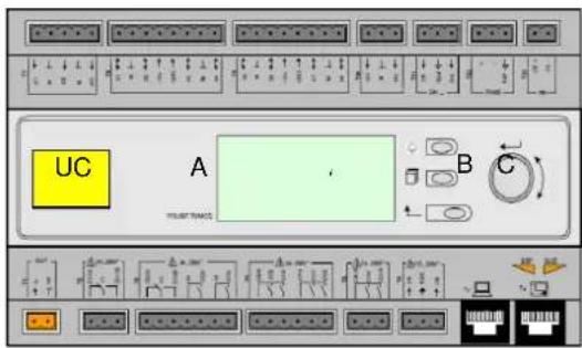
The standard HMI consists of an inbuilt display (A) with 3 buttons (B) and a push'n'roll control (C).
text_image
UC A B CThe keypad/display (A) consists of a 5-line by 22 character display. The function of the three buttons (B) is described below:

Alarm status (from any page it links with the page with alarm list, alarm log and alarm snapshot if available) Back to Main Page
Back to the previous level (it can be the Main Page)
The push'n'roll command (C) is used to scroll between the different menu pages, settings and data available on the HMI for the active password level. Rotating the wheel allows to navigate between lines on a screen (page) and to increase and decrease changeable values when editing. Pushing the wheel acts as an Enter Button and will jump from a link to the next set of parameters.
3.1 Navigating
When power is applied to the control circuit, the controller screen will be active and display the Home screen, which can also be accessed by pressing the Menu Button.
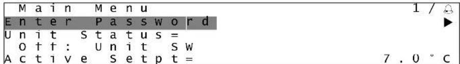
An example of the HMI screens is shown in the following picture.
| Main Menu 1 / 11 | |
| Enter Password | |
| Unit Status = | |
| 0ff: Unit SW | |
| Active Setpt = 7.0 °C |
A bell ringing in the top right corner will indicate an active alarm. If the bell doesn't move it means that the alarm has been acknowledged but not cleared because the alarm condition hasn't been removed. A LED will also indicate where the alarm is located between the unit or circuits.
text_image
M a i n M e n u 1 / E n t e r P a s s w o r d U n i t S t a t u s = O f f : U n i t S W A c t i v e S e t p t = 7 . 0 °CThe active item is highlighted in contrast, in this example the item highlighted in Main Menu is a link to another page. By pressing the push'n'roll, the HMI will jump to a different page. In this case the HMI will jump to the Enter Password page.
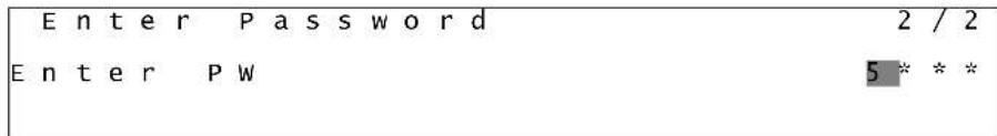
| Enter Password 2 / 2 | |
| Enter PW | * * * * |
3.2 Passwords
The HMI structure is based on access levels that means that each password will disclose all the settings and parameters allowed to that password level. Basic informations about the status can be accessed without the need to enter the password. The user UC handles two level of passwords:
| USER | 5321 |
| MAINTENANCE | 2526 |
The following information will cover all data and settings accessible with the maintenance password.
In the Enter Password screen, the line with the password field will be highlighted to indicate that the field on the right can be changed. This represents a setpoint for the controller. Pressing the push'n'roll the individual field will be highlighted to allow an easy introduction of the numeric password.
text_image
Enter Password 2 / 2 Enter PW 5 * * *The password will time out after 10 minutes and is cancelled if a new password is entered or the control powers down. Entering an invalid password has the same effect as continuing without a password. It is changeable from 3 to 30 minutes via the Timer Settings menu in the Extended Menus.
3.3 Editing
The Editing Mode is entered by pressing the navigation wheel while the cursor is pointing to a line containing an editable field. Pressing the wheel again cause the new value to be saved and the keypad/display to leave the edit mode and return to the navigation mode.
3.4 Mobile app HMI
The Daikin mAP mobile app HMI is provided for free and aims to simplify the interaction with this Daikin product. The app can be downloaded from the official stores with the following links (scan the QR code to access directly the download pages on the stores).

iOS

Android
To use the app is needed to pre-register an account and gain access to the specific unit to access. The access will be granted per unit base. A user can access multiple units after the app-tenant authorize this access. The procedure to register an account is in app. It's necessary to follow the sign in link in the app:

text_image
User login If you have a Dublin Applied Human account you can use it to log us. AUTHENTICATE WITH MERCOSIT At your own user SINN US Or log in with your Dublin mAP credentials MAIL INVOICE Target personal IP SINN
text_image
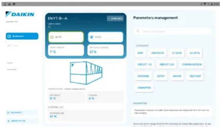
New user Enter your details to request access. MAIL Accessories The password is required to access the URL, but your URL will be displayed. Any other URL will not be requested. NAME ENGLISH COMPANY Let us inFORMATIZULAT VICTORAMENTO DE LAIR Personal, incursento expresamente al victoramento del fini (all personal) List!The mobile app will allow you to monitor all the relevant data, change the user related settings, trend data, update chiller software and more to come. App layout will adapt based on the device where the app is running and will look as follows:
text_image
DAIKIN EWYT-B--A UNIT STATUS 15 AUTO COOL Before setup 7°C Just actual setting 27% Parameters management User Data System CITIORS UNIT UNIT DATA CY DATA CY DATA CIRCUIT 1 ID CIRCUIT 2 ID CONGREGATION FEATURES SETUP UNITQ TEST UNIT UNMAPPED FAVOURTEE Parameters that you notice these departments are displayed terms; but now the test is empty. Select one of the ratings from the top menu to browse their parameters as user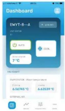
text_image
Dashboard EWYT-B--A + 20%RH UNIT GROUP 11 AUTO COOL Active input 7°C HIGHLIGHT IMPOSATOR - Warm temperature Entering 6.56743 °C Leaving 6.62539 °C EXTERNAL AIR
For further information consult the Quick Guide Daikin Map 1.0 D-EPMAP00101-23\_EN
3.5 Basic Control System Diagnostic
Microtech IV controller, extension modules and communication modules are equipped with two status LED (BSP and BUS) to indicate the operational status of the devices. The BUS LED indicates the status of the communication with the controller. The meaning of the two status LED is indicated below.
Main Controller (UC)
| BSP LED | Mode |
| Solid Green | Application running |
| Solid Yellow | Application loaded but not running (*) or BSP Upgrade mode active |
| Solid Red | Hardware Error (*) |
| Flashing Green | BSP startup phase. The controller needs time for starting. |
| Flashing Yellow | Application not loaded (*) |
| Flashing Yellow/Red | Fail safe mode (in case that the BSP upgrade was interrupted) |
| Flashing Red | BSP Error (software error*) |
| Flashing Red/Green | Application/BSP update or initialization |
(*) Contact Service.
Extension modules
| BSP LED | Mode | BUS LED | Mode |
| Solid Green | BSP running | Solid Green | Communication running, I/O working |
| Solid Red | Hardware Error (*) | Solid Red | Communication down (*) |
| Flashing Red | BSP Error (*) | Solid Yellow | Communication running but parameter from the application wrong or missing, or uncorrect factory calibration |
| Flashing Red/Green | BSP upgrade mode |
Communication modules
BSP LED (same for all modules)
| BSP LED | Mode |
| Solid Green | BPS running, communication with controller |
| Solid Yellow | BSP running, no communication with controller (*) |
| Solid Red | Hardware Error (*) |
| Flashing Red | BSP Error (*) |
| Flashing Red/Green | Application/BSP update |
(*) Contact Service.
BUS LED
| BUS LED | LON | Bacnet MSTP | Bacnet IP | Modbus |
| Solid Green | Ready for Communication. (All Parameter loaded, Neuron configured). Doesn't indicate a communication with other devices. | Ready for Communication. The BACnet Server is started. It doesn't indicate an active communication | Ready for Communication. The BACnet Server is started. It doesn't indicate an active communication | All Communication running |
| Solid Yellow | Startup | Startup | Startup. The LED stays yellow until the module receives a IP Address, therefore a link must be established. | Startup, or one configured channel not communicating to the Master |
| Solid Red | No Communication to Neuron (internal error, could be solved by downloading a new LON application) | BACnet Server down. Automatically a restart after 3 seconds are initiated. | BACnet Server down. Automatic restart after 3 seconds is initiated. | All configured Communications down. Means no communication to the Master. The timeout can be configured. In case that the timeout is zero the timeout is disabled. |
| Flashing Yellow | Communication not possible to the Neuron. The Neuron must be configured and set online over the LON Tool. |
3.6 Controller maintenance
The controller requires to maintain the installed battery. Every two years it's required to replace the battery. Battery model is: BR2032 and it is produced by many different vendors.
To replace the battery remove the plastic cover of the controller display using a screw driver as shown in the following pictures:

natural_image
Close-up of a vintage electronic device with a knob and indicator lights, no visible text or symbols
natural_image
Close-up of a white electronic device with a control panel and a finger inserted, placed on a blue surface (no visible text or symbols)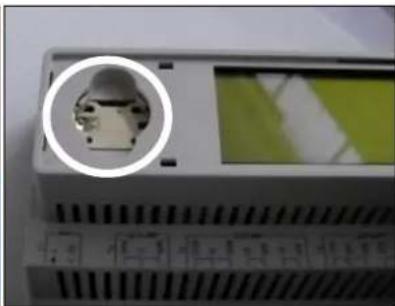
natural_image
Close-up of a device panel with a circular inset showing a small electronic component (no visible text or symbols)Be careful to avoid damages to the plastic cover. The new battery shall be placed in the proper battery holder which is highlighted in the picture, respecting the polarities indicated into the holder itself.
3.7 Optional Remote User Interface
As an option an external Remote HMI can be connected on the UC. The Remote HMI offers the same features as the inbuilt display plus the alarm indication done with a light emitting diode located below the bell button.
All viewing and setpoint adjustments available on the unit controller are available on the remote panel. Navigation is identical to the unit controller as described in this manual.

text_image
MicroTech®The Remote HMI can be extended up to 700m using the process bus connection available on the UC. With a daisy-chain connection as below, a single HMI can be connected to up to 8 units. Refer to the specific HMI manual for details.
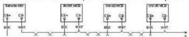
flowchart
graph LR
    A["RSROM"] --> B["UDTM"]
    B --> C["UDTM NOS"]
    C --> D["UDTM NOS"]
    D --> E["UDTM NOS"]
    A -->|CE+| F["BUK"]
    A -->|CE-| G["WHT"]
    B -->|CE+| H["BUK"]
    B -->|CE-| I["WHT"]
    C -->|CE+| J["BUK"]
    C -->|CE-| K["WHT"]
    D -->|CE+| L["BUK"]
    D -->|CE-| M["WHT"]
    E -->|CE+| N["BUK"]
    E -->|CE-| O["WHT"]
3.8 Embedded Web Interface
The Microtech IV controller has an embedded web interface that can be used to monitor the unit when connected to a local network. It is possible to configure the IP addressing of the Microtech IV as a fixed IP of DHCP depending on the network configuration.
With a common web browser a PC can connect with the unit controller entering the IP address of the controller or the host name, both visible in the "About Chiller" page accessible without entering a password.
When connected, it will be required to enter a user name and a password. Enter the following credential to get access to the web interface:
User Name: Daikin
Password: Daikin@web
The Main Menu page will be displayed. The page is a copy of the onboard HMI and follows the same rules in terms of access levels and structure.
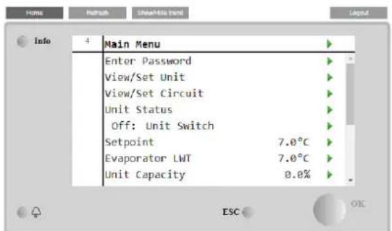
text_image
Home Refresh User@File Bend Legend Info 4 Main Menu Enter Password View/Set Unit View/Set Circuit Unit Status Off: Unit Switch Setpoint 7.0°C Evaporator LWT 7.0°C Unit Capacity 0.0%
line
| Date | Setpoint | Evaporator EWT | | ---------- | -------- | -------------- | | 08:50:45 | 12 | 7 | | 08:50:50 | 12 | 7 | | 08:50:55 | 12 | 7 | | 08:50:60 | 12 | 7 | | 08:50:65 | 12 | 7 | | 08:50:70 | 12 | 7 | | 08:50:75 | 12 | 7 | | 08:50:80 | 12 | 7 | | 08:50:85 | 12 | 7 | | 08:50:90 | 12 | 7 | | 08:50:95 | 12 | 7 | | 08:50:100 | 12 | 7 | | 08:50:105 | 12 | 7 | | 08:50:110 | 12 | 7 | | 08:50:115 | 12 | 7 | | 08:50:120 | 12 | 7 | | 08:50:125 | 12 | 7 | | 08:50:130 | 12 | 7 | | 08:50:135 | 12 | 7 | | 08:50:140 | 12 | 7 | | 08:50:145 | 12 | 7 | | 08:50:150 | 12 | 7 | | 08:50:155 | 12 | 7 | | 08:50:160 | 12 | 7 | | 08:50:165 | 12 | 7 | | 08:50:170 | 12 | 7 | | 08:50:175 | 12 | 7 | | 08:50:180 | 12 | 7 | | 08:50:185 | 12 | 7 | | 08:50:190 | 12 | 7 | | 08:50:195 | 12 | 7 | | 08:50:200 | 12 | 7 | | 08:50:205 | 12 | 7 | | 08:50:210 | 12 | 7 | | 08:50:215 | 12 | 7 | | 08:50:220 | 12 | 7 | | 08:50:225 | 12 | 7 | | 08:50:230 | 12 | 7 | | 08:50:235 | 12 | 7 | | 08:50:240 | 12 | 7 | | 08:50:245 | 12 | 7 | | 08:50:250 | 12 | 7 | | 08:50:255 | 12 | 7 | | 08:50:260 | 12 | 7 | | 08:50:265 | 12 | 7 | | 08:50:270 | 12 | 7 | | 08:50:275 | 12 | 7 | | 08:50:280 | 12 | 7 | | 08:50:285 | 12 | 7 | | 08:50:290 | 12 | 7 | | 08:50:295 | 12 | 7 | | 08:50:300 | 12 | 7 | | 08:50:305 | 12 | 7 | | ... | ... | ... | | Date | Value | Value | | End | ... | ... |In addition it allows to trend log a maximum of 5 different quantities. It's required to click on the value of the quantity to monitor and the following additional screen will become visible:
Depending on the web browser and its version the trend log feature may not be visible. It's required a web browser supporting HTML 5 like for example:
• Microsoft Internet Explorer v.11,
• Google Chrome v.37,
- Mozilla Firefox v.32.
These software are only an example of the browser supported and the versions indicated have to be intended as minimum versions.
4.1 Chiller On/Off
Starting from factory setup, unit On/Off can be managed by the user using the selector Q0, placed in the electrical panel, which can switch between three positions: 0 - Local - Remote.
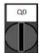
0
Unit is disabled
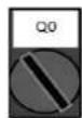
Loc (Local)
Unit is enabled to start the compressors

Rem (Remote)
Unit On/Off is managed through the "Remote On/Off" physical contact.
Closed contact means unit enabled.
Opened contact means unit disabled.
Refer to the electrical wiring diagram, Field Wiring Connection page, to find the references about Remote On/Off contact. Generally, this contact is used to bring out from the electrical panel the on/off selector.
Some chiller models can be equipped with additional selectors Q1 - Q2 used to enable or disabled specific refrigerant circuit.

0
Circuit 1 is disabled.
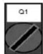
1
Circuit 1 is enabled.
Unit controller provides also additional software features to manage unit start/stop, that are set by default to allow unit start:
- Keypad On/Off
- Scheduler (Time programmed On/Off)
- Network On/Off (optional with communication modules)
4.1.1 Keypad On/Off
In the main page, scroll down until Unit Enable menu, where are available all settings to manage unit and circuits start/stop.

text_image
Info Main Menu Enter Password Unit Status Off: Unit Switch Setpoint 7.0°C Evaporator LWT 7.0°C Unit Capacity 0.0% Unit Enable Yes Unit Mode Cool
text_image
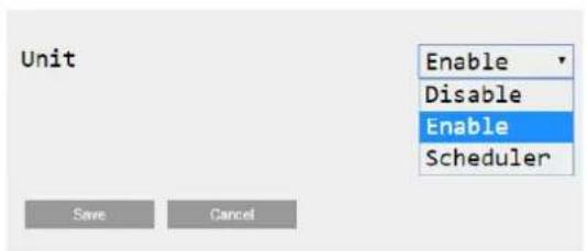
Info 4 Unit Enable Unit Enable ▶ Circuit #1 Enable ▶ Circuit #2 Enable ▶ ESC OK| Parameter | Range | Description |
| Unit | Disable | Unit disabled |
| Enable | Unit enabled | |
| Scheduler | Unit start/stop can be time programmed for each weekday | |
| Circuit #X | Disable | Circuit #X disabled |
| Enable | Circuit #X enabled | |
| Test | Circuit #X in test mode. This feature has to be used only from trained person or Daikin service |
text_image
Unit Enable Disable Enable Scheduler Save Cancel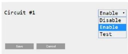
text_image
Circuit #1 Enable Disable Enable Test Save Cancel4.1.2 Scheduler and Silent mode functionalities
The Scheduler function can be used when is required an automatic chiller start/stop programming.
To use this function, follow below instructions:
- Q0 selector = Local (refer to 4.1)
- Unit Enable = Scheduler (refer to 4.1.1)
- Controller date and time properly set (refer to 4.7)
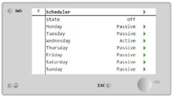
Scheduler programming is available going in Main Page → View/Set Unit → Scheduler menu
text_image
Info 6 Scheduler State Off Monday Passive Tuesday Passive Wednesday Active Thursday Passive Friday Passive Saturday Passive Sunday Passive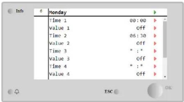
text_image
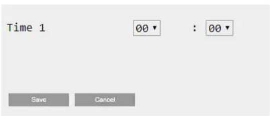
Info 6 Monday Time 1 00:00 Value 1 Off Time 2 06:30 Value 2 Off Time 3 * : * Value 3 Off Time 4 * : * Value 4 OffFor each weekday can be programmed up to six time bands with a specific operating mode. First operating mode starts at Time 1, ends at Time 2 when will start the second operating mode and so on until the latest.
text_image
Time 1 00▼ : 00▼ Save Cancel
text_image
Value 1 OFF Off On 1 On 2 On 1 - Silent On 2 - Silent Save CancelDepending on unit type, different operating modes are available:
| Parameter | Range | Description |
| Value 1 | off | Unit disabled |
| On 1 | Unit enabled – Water setpoint 1 selected | |
| On 2 | Unit enabled – Water setpoint 2 selected | |
| On 1 - Silent | Unit enabled – Water setpoint 1 selected – Fan silent mode enabled | |
| On 2 - Silent | Unit enabled – Water setpoint 2 selected – Fan silent mode enabled |
When the Fan Silent Mode function is enabled the chiller noise level is reduced decreasing the maximum speed allowed for fans. Following table reports how much maximum speed is decreased for the different unit types.
| Unit noise class | Normal maximum fan speed [rpm] | Silent mode maximum fan speed [rpm] |
| Standard | 900 | 700 |
| Low | 900 | 700 |
| Reduced | 700 | 500 |

All data reported in the table, will be respected only if the chiller is operating within its operating limits.
The Fan Silent Mode function can be enabled only for units equipped with VFD fans.
4.1.3 Network On/Off
Chiller On/Off can be managed also with serial protocol, if the unit controller is equipped with one or more communication modules (BACNet, Modbus or LON). In order to control the unit over the network, follow below instructions:
- Q0 selector = Local (refer to 4.1)
- Unit Enable = Enable (refer to 4.1.1)
- Control Source = Network (refer to 4.5)
- Close the contact Local/Network Switch (refer to 4.5), when required!
4.2 Water Setpoints
Purpose of this unit is to cool or to heat (in case of heat pump) the water temperature, to the setpoint value defined by the user and displayed in the main page:
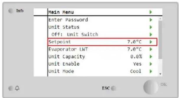
text_image
Info Main Menu Enter Password Unit Status Off: Unit Switch Setpoint 7.0°C Evaporator LWT 7.0°C Unit Capacity 0.0% Unit Enable Yes Unit Mode Cool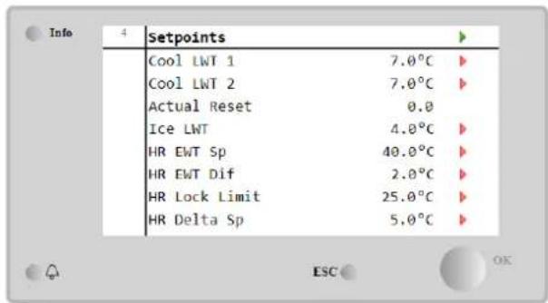
text_image
Info 4 Setpoints Cool LWT 1 7.0°C Cool LWT 2 7.0°C Actual Reset 0.0 Ice LWT 4.0°C HR EWT Sp 40.0°C HR EWT Dif 2.0°C HR Lock Limit 25.0°C HR Delta Sp 5.0°CThe unit can work with a primary or a secondary setpoint, that can be managed as indicated below:
- Keypad selection + Double Setpoint digital contact
- Keypad selection + Scheduler Configuration
- Network
- Setpoin Reset function
As first step the primary and secondary setpoints need to be defined. From main menu, with user password, press on Setpoint.
| Parameter | Range | Description |
| Cool LWT 1 | Ranges of the Cool, Heat, Ice setpoint are reported in the IOM of every specific unit. | Primary cooling setpoint. |
| Cool LWT 2 | Secondary cooling setpoint. | |
| Actual Reset | This item is visible only when the Setpoint Reset function is enabled and it shows the actual reset applied to the basic setpoint | |
| Heat LWT 1 | Primary heating setpoint. | |
| Heat LWT 2 | Secondary heating setpoint. | |
| Ice LWT | Setpoint for Ice mode. |
The change between primary and secondary setpoint can be performed using the Double setpoint contact, always available in the user terminal box, or through the Scheduler function.
Double setpoint contact works as below:
- Contact opened, the primary setpoint is selected
- Contact closed, the secondary setpoint is selected
In order to change between primary and secondary setpoint with the Scheduler, refer to the section 4.1.2.

When the scheduler function is enabled, the Double setpoint contact is ignored

When the operating mode Cool/Ice w/Glycol is selected, the Double Setpoint contact will be used to switch between the Cool and Ice mode, producing no change on the active setpoint
To modify the active setpoint through network connection, refer to Network control section 4.5.
The active setpoint can further modified using the Setpoint Reset function as explained in the section 4.10.2.
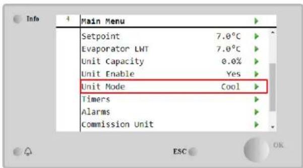
4.3 Unit Mode
The Unit Mode is used to define if the chiller is working to produce chilled or heated water. Current mode is reported in the main page to the item Unit Mode.
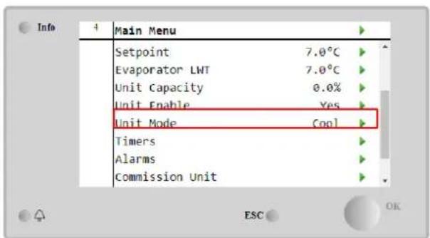
text_image
Info + Main Menu Setpoint 7.0°C Evaporator LWT 7.0°C Unit Capacity 0.0% Unit Enable Yes Unit Mode Cool Timers Alarms Commission Unit ESC OK
text_image
Info Unit Mode Mode Cool Energy Saving Yes Heating Only Not ActiveDepending on the unit type, different operating modes can be selected entering, with maintenance password, in the Unit Mode menu. In the table below are listed and explained all modes.
| Parameter | Range | Description | Unit Range |
| Mode | Cool | Set if chilled water temperature up to 4°C is required. No glycol is generally needed in the water circuit, unless ambient temperature may reach low values. | A/C |
| Cool w/Glycol | Set if chilled water temperature below 4°C is required. This operation requires proper glycol/water mixture in the evaporator water circuit. | A/C | |
| Cool/Ice w/Glycol | Set in case a dual cool/ice mode is required. The switch between the two modes is performed using the contact physical Double Setpoint.Double Setpoint opened: the chiller will work in cooling mode with the Cool LWT being as the Active Setpoint.Double Setpoint closed: The chiller will work in Ice mode with the Ice LWT as the Active Setpoint. | A/C | |
| Ice w/Glycol | Set if ice storage is required. The application requires the compressors to operate at full load until the ice bank is completed, and then to stop for at least 12 hours. In this mode the compressor(s) will not operate at part load, but will work only in on/off mode. | A/C | |
| The following modes allow to switch the unit between heat mode and one of the previous cool mode (Cool, Cool w/Glycol, Ice) | |||
| Heat/Cool | Set in case a dual cool/heat mode is required. This setting implies an operation with double functioning which is activated through the Cool/Heat switch on the electric box.Switch COOL: The chiller will work in cooling mode with the Cool LWT as the Active Setpoint.Switch HEAT: The chiller will work in heat pump mode with the Heat LWT as the Active Setpoint. | Heat Pump Only | |
| Heat/Cool w/Glycol | Set in case a dual cool/heat mode is required. This setting implies an operation with double functioning which is activated through the Cool/Heat switch on the electric box.Switch COOL: The chiller will work in cooling mode with the Cool LWT as the Active Setpoint.Switch HEAT: The chiller will work in heat pump mode with the Heat LWT as the Active Setpoint. | A/C | |
| Heat/Ice w/Glycol | Set in case a dual Ice/Heat mode is required. This setting implies an operation with double functioning which is activated through the Cool/Heat switch on the electric box.Switch ICE: The chiller will work in cooling mode with the Ice LWT as the Active Setpoint.Switch HEAT: The chiller will work in heat pump mode with the Heat LWT as the Active Setpoint. | A/C | |
| Test | Enables the Manual Control of the unit. The manual test feature helps in debugging and checking the operational status of actuators. This feature is accessible only with the maintenance password in the main menu. To activate the test feature is required to disable the Unit from the Q0 switch and change the available mode to Test. | A/C | |
| Energy Saving | No, Yes | Disable/Enable of the energy saving function | |
| Heating Only | Not Active, Active | Indicates if the unit can work ONLY in heating mode or not | Heat Pump only |
Like the On/Off and setpoint control, also the unit mode can be modified from network. Refer to Network control section 4.5 for more details.
4.3.1 Heat/Cool Switch (Heat Pump Only)
Starting from factory setup, Heat mode switch can be managed by the user using the selector QHP, placed in the electrical panel, which can switch between three positions: 0 - 1.

chiller
Unit will work in Cooling Mode

Loc (Local)
Unit will work in Heating mode
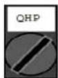
Rem (Remote)
Unit Operating mode is managed through the "Remote" control through BMS communication.
In order to enable the Heat mode, the Unit mode must be set in "Heat/Cool" mode, and the QHP switch must be set in Loc position.
4.3.2 Energy Saving mode
Some unit types provide the possibility to enable an energy saving function, that reduces the power consumption deactivating the compressors crankcase heater, when the chiller is Disabled.
This mode implies that the time needed to start the compressors, after an Off period, could be delayed until a maximum of 90 minutes.
For time critical application, the energy saving function can be disabled by the user to ensure the compressor start within 1 minute from unit On command.
text_image
Info 4 Main Menu Setpoint 7.0°C Evaporator LWT 7.0°C Unit Capacity 0.0% Unit Enable Yes Unit Mode Cool Timers Alarms Commission Unit ESC OK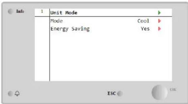
text_image
Info 1 Unit Mode Mode Cool Energy Saving Yes ESC OK4.4 Unit Status
Unit controller provides in the main page some information about chiller status. All chiller states are listed and explained below:
| Parameter | Overall status | Specific status | Description |
| Unit Status | Auto: | Unit is in Auto control. The pump is running and at least one compressor is running. | |
| Wait For Load | Unit is in standby because the thermostatic control satisfies the active setpoint. | ||
| Water Recirc | Water pump is running in order to equalize the water temperature in the evaporator. | ||
| Wait For Flow | Unit pump is running but the flow signal still indicates a lack of flow through the evaporator. | ||
| Max Pulldown | Unit thermostatic control is limiting the unit capacity as the water temperature is dropping too quickly. | ||
| Capacity Limit | Demand limit has been hit. Unit capacity will not further increase. | ||
| Current Limit | Maximum current has been hit. Unit capacity will not further increase. | ||
| Silent Mode | Unit is running and Silent Mode is enabled | ||
| off: | Master DisableIce Mode Timer | Unit is disabled by the Master Slave functionThis status can be shown only if the unit can work in Ice Mode. The unit is off because the Ice setpoint has been satisfied. Unit will remain off until the Ice Timer has expired. | |
| OAT Lockout | The unit cannot run because the Oustide Air Temperature is below the limit foreseen for the condenser temperature control system installed in this Unit. If the Unit has to run anyway, check with your local maintenance how to proceed. | ||
| Circuits Disabled | No circuit is available to run. All circuits can be disabled by their individual enable switch or can be disabled by a component safety condition active or can be disabled by keypad or can be all in alarms. Check the individual circuit status for further details. | ||
| Unit Alarm | A unit alarm is active. Check the alarm list to see what is the active alarm inhibiting the unit to start and check if the alarm can be cleared Refer to section 5. before proceeding. | ||
| Keypad Disable | The Unit has been disabled by keypad. Check with your local maintenance if it can be enabled. | ||
| Network Disabled | Unit is disabled by Network. | ||
| Unit Switch | The Q0 selector is set to 0 or the or the Remote On/Off contact is opened. | ||
| Test | Unit mode set to Test. This mode is activated to check operability of onboard actuators and sensors. Check with the local maintenance if the Mode can be reverted to the one compatible with unit application (View/Set Unit – Set-Up – Available Modes). | ||
| Scheduler Disable | Unit is disabled by Scheduler programming | ||
| Pumpdown | Unit is performing the pumpdown procedure and d it will stop within few minutes |
4.5 Network Control
When the unit controller is equipped with one or more communication modules the Network Control feature can be enabled, which gives the possibility to control the unit via serial protocol (Modbus, BACNet or LON).
To allow unit's control from network, follow below instructions:
- Close the physical contact "Local/Network Switch". Refer to unit electrical wiring diagram, Field Wiring Connection page, to find the references about this contact.
- Go to Main Page → View/Set Unit → Network Control Set Controls Source = Network
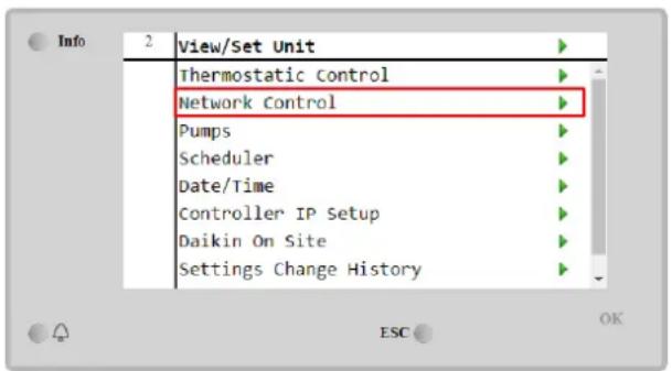
text_image
Info 2 View/Set Unit Thermostatic Control Network Control Pumps Scheduler Date/Time Controller IP Setup Daikin On Site Settings Change History
text_image
Info 4 Network Control Control Source Network Enable Disable Mode Cool Cool LWT 7.0°C Ice LWT 4.4°C Heat LWT 45.0°C Capacity Limit 100%Network Control menu returns all main values received from serial protocol.
| Parameter | Range | Description |
| Control Source | Local | Network control disabled |
| Network | Network control enabled | |
| Enable | - | On/Off command from network |
| Mode | - | Operating mode from network |
| Cool LWT | - | Cooling water temperature setpoint from network |
| Ice LWT | - | Ice water temperature setpoint from network |
| Heat LWT | - | Heating water temperature setpoint from network |
| FreeCooling | Enable/Disable | On/Off command from network |
| Capacity Limit | - | Capacity limitation from network |
Refer to communication protocol documentation for specific registers addresses and the related read/write access level.
4.6 Thermostatic Control
Thermostatic control settings allow to set up the response to temperature variations. Default settings are valid for most application, however plant specific conditions may require adjustments in order to have a smooth control or a quicker response of the unit.
The control will start the first compressor if the controlled temperature is higher (Cool Mode) or lower (Heat Mode) than the active setpoint of at least a Start Up DT value, whereas other compressors are started, step by step, if the controlled temperature is higher (Cool Mode) or lower (Heat Mode) than the active setpoint (AS) of at least a Stage Up DT (SU) value. Compressors stop if performed following same procedure looking to the parameters Stage Down DT and Shut Down DT.
| Cool Mode | Heat Mode | |
| First compressor start | Controlled Temperature > Setpoint + Start Up DT | Controlled Temperature < Setpoint - Start Up DT |
| Other compressors start | Controlled Temperature > Setpoint + Stage Up DT | Controlled Temperature < Setpoint - Stage Up DT |
| Last compressor stop | Controlled Temperature < Setpoint - Shut Dn DT | Controlled Temperature > Setpoint - Shut Dn DT |
| Other compressors stop | Controlled Temperature < Setpoint - Stage Dn DT | Controlled Temperature > Setpoint - Stage Dn DT |
A qualitative example of compressors start-up sequence in cool mode operation is shown in the graph below.
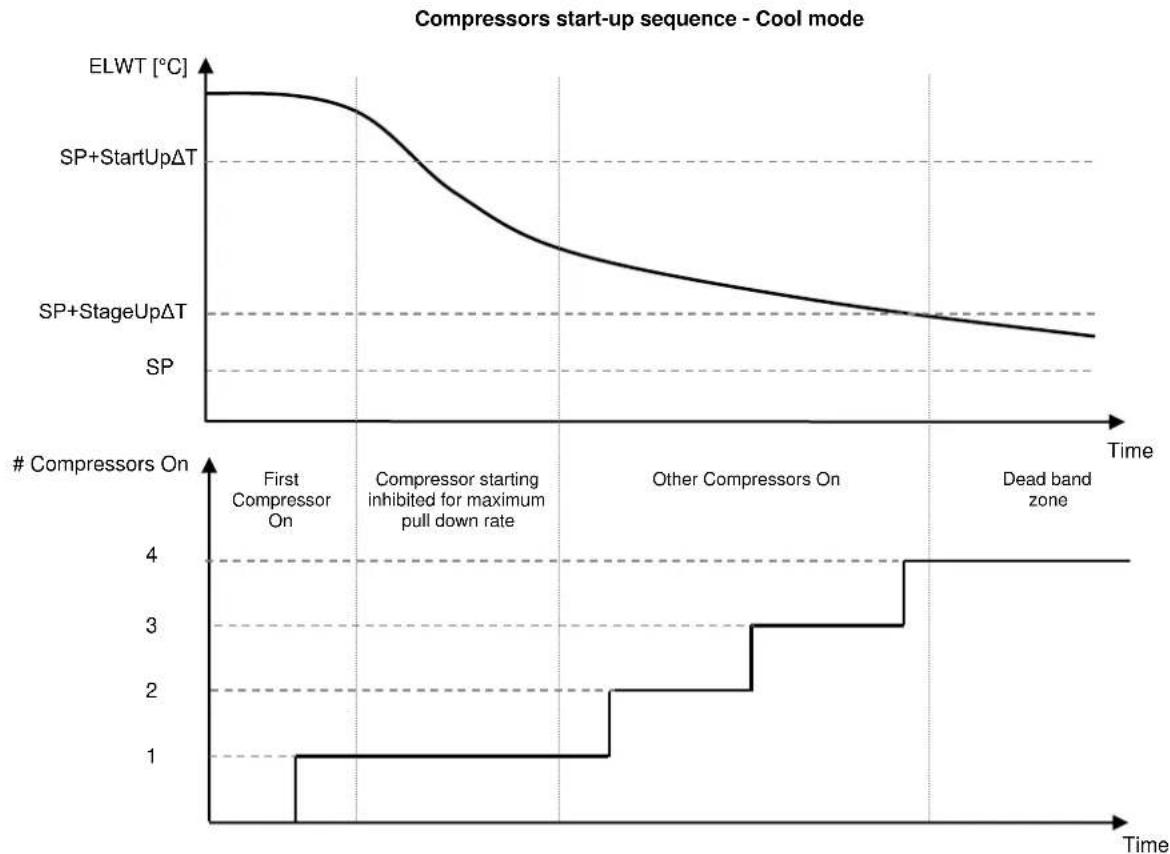
line
| Time Segment | ELWT [°C] | # Compressors On | | --------------------------------- | --------- | ---------------- | | First Compressor On | High | 1 | | Compressor starting inhibited for maximum pull down rate | Decreasing | 2 | | Other Compressors On | Decreasing | 3 | | Dead band zone | Decreasing | 4 |Thermostatic control settings are accessible from Main Page→Thermostatic Control
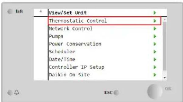
text_image
View/Set Unit Thermostatic Control Network Control Pumps Power Conservation Scheduler Date/Time Controller IP Setup Daikin On Site
text_image
Info 4 Thermostatic Control Start Up DT 2.5°C Shut Down DT 1.5°C Stage Up DT 1.0°C Stage Down DT 1.0°C Stage Up Delay 120s Stage Down Delay . 30s Ice Cycle Delay 12h| Parameter | Range | Description |
| Start Up DT | 0.5-8°C | Delta temperature respect the active setpoint to start the unit (startup of first compressor) |
| Shut Down DT | 0.5-3°C | Delta temperature respect the active setpoint to stop the unit (shutdown of latest compressor) |
| Stage Up DT | 0.5-2.5°C | Delta temperature respect the active setpoint to start a compressor |
| Stage Down DT | 0.5-1.5°C | Delta temperature respect the active setpoint to stop a compressor |
| Stage Up Delay | 2-8 min | Minimum time between the compressors startup |
| Stage Down Delay | 10-60 s | Minimum time between the compressors shutdown |
| Ice Cycle Delay | 1-23 h | Unit standby period during Ice mode operation |
4.7 Date/Time
The unit controller is able to take stored the actual date and time, that are used for:
- Scheduler
- Cycling of standby chiller with Master Slave configuration
- Alarms Log
Date and time can be modified going in View/Set Unit → Date/Time
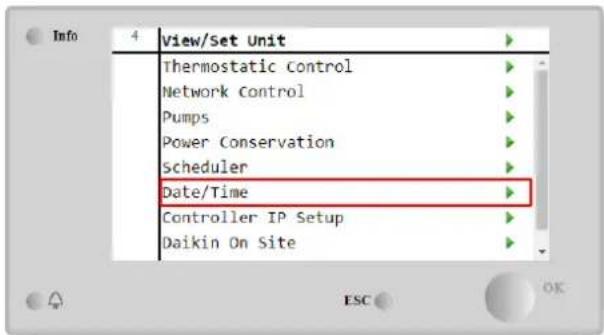
text_image
Info 4 View/Set Unit Thermostatic Control Network Control Pumps Power Conservation Scheduler Date/Time Controller IP Setup Daikin On Site
text_image
Date/Time Time 14:43:27 Date 05/15/2018 Day Thursday UTC Difference -60min Daylight Saving Time: Enable Yes Start Month Mar Start Week 2ndWeek| Parameter | Range | Description |
| Time | Actual date. Press to modify. Format is hh:mm:ss | |
| Date | Actual time. Press to modify. Format is mm/dd/yy | |
| Day | Returns the day of the week. | |
| UTC Difference | Coordinated universal time. | |
| Daylight Saving Time: | ||
| Enable | No, Yes | It is used to enable/disable the automatic switch of the Daylight Saving Time |
| Start Month | NA, Jan...Dec | DayLight Saving time start month |
| Start Week | 1st...5th week | DayLight Saving time start week |
| End Month | NA, Jan...Dec | DayLight Saving time end month |
| End Week | 1st...5th week | DayLight Saving time end week |

Remember to check periodically the controller battery in order to maintain updated date and time even when there is no electrical power. Refer to controller maintenance section
4.8 Pumps
The UC can manage one or two water pumps. Number of pumps and their priority can be set from Main Page→View/Set Unit→Pumps.

text_image
Info 4 View/Set Unit Thermostatic Control Network Control Pumps Power Conservation Scheduler Date/Time Controller IP Setup Daikin On Site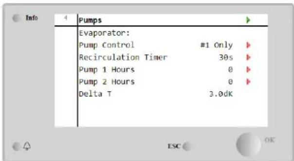
text_image
Info 4 Pumps Evaporator: Pump Control #1 Only ▶ Recirculation Timer 30s ▶ Pump 1 Hours 0 ▶ Pump 2 Hours 0 ▶ Delta T 3.0dK| Parameter | Range | Description |
| Pump Control | #1 Only | Set to this in case of single pump or twin pump with only #1 operational (f.e. in case of maintenance on #2) |
| #2 Only | Set to this in case of twin pump with only #2 operational (f.e. in case of maintenance on #1) | |
| Auto | Set for automatic pump start management. At each chiller start, the pump with the least number of hours will be | |
| #1 Primary | Set to this in case of twin pump with #1 running and #2 as a backup | |
| #2 Primary | Set to this in case of twin pump with #2 running and #1 as a backup | |
| Recirculation Timer | Minimum time required within flow switch has to in order to allow unit startup | |
| Pump 1 Hours | Pump 1 running hours | |
| Pump 2 Hours | Pump 2 running hours |
4.9 External Alarm
The External Alarm is a digital contact that can be used to communicate to the UC an abnormal condition, coming from an external device connected to the unit. This contact is located in the customer terminal box and depending on the configuration can cause a simple event in the alarm log or also the unit stop. The alarm logic associated to the contact is the following:
| Contact state | Alarm State | Note |
| Opened | Alarm | The alarm is generated if the contact remains opened for at least 5 seconds |
| Closed | No Alarm | The alarm is reset just the contact is closed |
The configuration is performed from the Commissioning → Configuration → Options menu

text_image
Info 1 Options Apply Changes No Communication 1 None Communication 2 None Communication 3 None Demand Limit No Energy Meter Nemo D4-Le Ext Alarm No Free Cooling No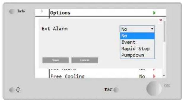
text_image
Info 1 Options Ext Alarm Save Cancel Ext Alarm Free Cooling No Event Rapid Stop Pumpdown ESC OK| Parameter | Range | Description |
| Ext Alarm | Event | Event configuration generates an alarm in the controller but takes the unit running |
| Rapid Stop | Rapid Stop configuration generates an alarm in the controller and performs a rapid stop of the unit | |
| Pumpdown | Pumpdown configuration generates an alarm in the controller and performs a pumpdown procedure to stop the unit. |
4.10 Power Conservation
In this chapters will be explained the functions used to reduce the unit power consumption:
- Demand Limit
- Setpoint Reset
4.10.1 Demand Limit
The "Demand limit" function allows the unit to be limited to a specified maximum load. Capacity limit level is regulated using an external 4-20 mA signal with a linear relationship shown in the picture below. A signal of 4 mA indicates the maximum capacity available whereas a signal of 20 mA indicates the minimum capacity available. In order to enable this option, go to Main Menu → Commission Unit → Configuration → Options and set the Demand Limit parameter to Yes.

line
| Demand Limit [mA] | Capacity Limit [%] | | ----------------- | ------------------ | | 4 | Maximum Capacity | | 20 | Minimum Capacity |Graph 1 Demand Limit[mA] vs Capacity Limit[%]
It is worth pointing out that it is not possible to shut down the unit using the demand limit function, but only to unload it to its minimum capacity.
Note that this function does a real capacity limitation only if the unit is equipped with Screw compressors. In case of Scroll compressors, the demand limit operates a discretization of the overall unit capacity according to the actual number of compressors, and, depending on the external signal value, it enables only a subset of the total number of compressors, as shown in table below:
| Number of Compressor | Demand Limit Signal [mA] | Maximum number of compressors On |
| 4 | 4 < < 8 | 4 |
| 8 < < 12 | 3 | |
| 12 < < 16 | 2 | |
| 16 < < 20 | 1 | |
| 5 | 4 < < 7.2 | 5 |
| 7.2 < < 10.4 | 4 | |
| 10.4 < < 13.6 | 3 | |
| 13.6 < < 16.8 | 2 | |
| 16.8 < < 20.0 | 1 | |
| 6 | 4 < < 6.7 | 6 |
| 6.7 < < 9.3 | 5 | |
| 9.3 < < 12 | 4 | |
| 12 < < 14.7 | 3 | |
| 14.7 < < 17.3 | 2 | |
| 17.3 < < 20 | 1 |
All info about this function are reported in the Main Menu → Commission Unit → Configuration → Options → Demand Limit page.
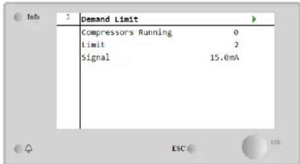
text_image
2 Demand Limit Compressors Running 0 Limit 2 Signal 15.0mA4.10.2 Setpoint Reset
The "Setpoint Reset" function is able to override the chilled water temperature active setpoint when certain circumstances occur. The aim of this function is to reduce the unit energy consumption whilst maintaining the same comfort level. To this purpose, three different control strategies are available:
- Setpoint Reset by Outside Air Temperature (OAT)
- Setpoint Reset by an external signal (4-20mA)
- Setpoint Reset by Evaporator T (EWT)
In order to set the desired setpoint-reset strategy, go to Main Menu → Commission Unit → Configuration → Options and modify the Setpoint Reset parameter, according to the following table:
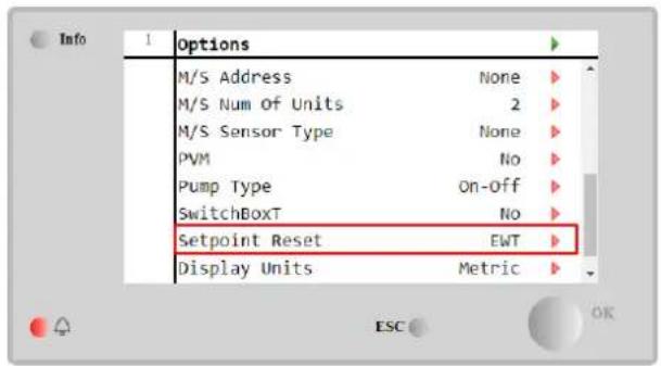
text_image
Info 1 Options M/S Address None M/S Num Of Units 2 M/S Sensor Type None PVM No Pump Type On-Off SwitchBoxT No Setpoint Reset EWT Display Units Metric ESC OK
text_image
Info 2 Options Setpoint Reset Save Cancel Apply Changes No No 4 - 20mA DT OAT ESC OK| Parameter | Range | Description |
| LWT Reset | No | Setpoint reset not enabled |
| 4-20mA | Setpoint reset enabled by an external signal between 4 and 20mA | |
| DT | Setpoint reset enabled by Evaporator Water Temperature | |
| OAT | Setpoint reset enabled by Outside Air Temperature |
Each strategy needs to be configured (although a default configuration is available) and its parameters can be set navigating to Main Menu → view/Set Unit → Power Conservation→ Setpoint Reset.
Note that the parameters corresponding to a specific strategy will be available only once the Setpoint Reset has been set to a specific value and the UC has been restarted.
4.10.2.1 Setpoint Reset by OAT (A/C units only)
When the OAT is selected as Setpoint Reset option, the LWT active setpoint(AS) is calculated applying a correction to the basic setpoint that depends on the ambient temperature (OAT) and on the current Unit Mode (Heating mode or Cooling mode). Several parameters can be configured, and they are accessible from the Setpoint Reset menu, as shown below:

text_image
Info 4 Setpoint Reset Actual Reset 2.5°C Max Reset 5.0°C ▶ Max Reset OAT 25.0°C ▶ Start Reset OAT 15.0°C ▶ Evaporator EWT 12.0°C OAT 20.0°C Signal 4.0mA ESC OK| Parameter | Default | Range | Description |
| Actual Reset | Actual Reset shows which is the correction that will applied to the base setpoint | ||
| Max Reset (MR) | 5.0°C | 0.0°C÷10.0°C | Max Reset setpoint. It represents the maximum temperature variation that the selection of the OAT option can cause on the LWT. |
| Max Reset OAT (MROAT) | 15.5°C | 10.0°C÷29.4°C | It represents the “threshold temperature” that correspond to the maximum setpoint variation. |
| Start Reset OAT(SROAT) | 23.8°C | 10.0°C÷29.4°C | It represents the “threshold temperature” of the OAT to activate the LWT setpoint reset, i.e. the LWT setpoint is overwritten only if the OAT reaches/overpasses the SROAT. |
| Delta T | Is the actual evaporator delta temperature. Entering – Leaving water temperature | ||
| OAT | Actual outside ambient temperature | ||
| Signal | Actual input current read on the terminals Setpoint Reset |
Provided the unit is set in Cooling mode (Heating mode), the more the ambient temperature drops below (goes beyond) the SROAT, the more the LWT active setpoint (AS) is increased(decreased), until the OAT reaches the MROAT limit. When the OAT overpasses the MROAT, the active setpoint does not increase(decrease) anymore, and it remains stable to its maximum(minimum) value, i.e. AS = LWT + MR(-MR).
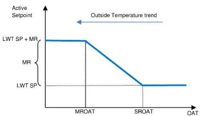
line
| OAT | Active Setpoint | | ------- | --------------- | | MROAT | LWT SP + MR | | SROAT | LWT SP |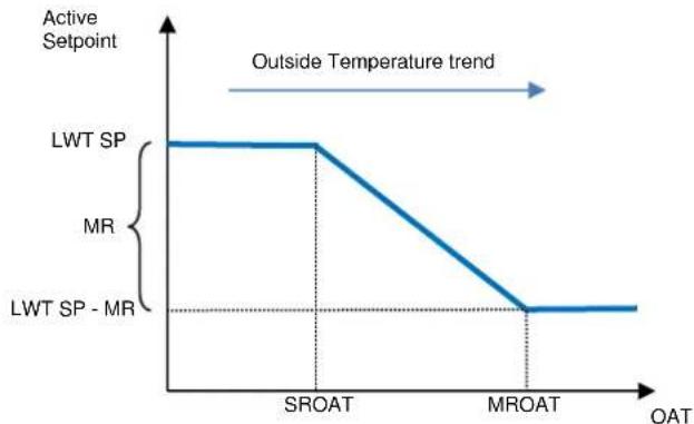
line
| OAT | Active Setpoint | | ------- | --------------- | | SROAT | MR | | MROAT | MR |Graph 2 Outside Ambient Temperature vs Active Setpoint - Cooling mode(left)/ Heating mode(right)
4.10.2.2 Setpoint Reset by External 4-20Ma signal
When the 4-20mA is selected as Setpoint Reset option, the LWT active setpoint(AS) is calculated applying a correction based on an external 4-20mA signal: 4 mA corresponds to 0°C correction, i.e. AS = LWT setpoint, whereas 20 mA corresponds to a correction of the Max Reset (MR) quantity, i.e. AS = LWT setpoint + MR(-MR) as shown in the following table:

text_image
Info Setpoint Reset Actual Reset 1.9°C Max Reset 5.0°C Delta T 3.0dK OAT 20.0°C Signal 10.0mA| Parameter | Default | Range | Description |
| Actual Reset | Actual Reset shows which is the correction that will applied to the base setpoint | ||
| Max Reset (MR) | 5.0°C | 0.0°C ÷ 10.0°C | Max Reset setpoint. It represents the maximum temperature variation that the selection of the 4-20mA option can cause on the LWT. |
| Delta T | Is the actual evaporator delta temperature. Entering – Leaving water temperature | ||
| OAT | Actual outside ambient temperature | ||
| Signal | Actual input current read on the terminals Setpoint Reset |
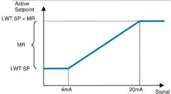
line
| Signal | Active Setpoint | | ------ | --------------- | | 4mA | LWT SP | | 20mA | MR |
line
| Signal | Active Setpoint | | ---------- | --------------- | | 4mA | LWT SP | | 20mA | MR |Graph 3 External signal 4-20mA vs Active Setpoint - Cooling mode(left)/ Heating mode(right)
4.10.2.3 Setpoint Reset by DT
When the DT is selected as Setpoint Reset option, the LWT active setpoint(AS) is calculated applying a correction based on the temperature difference T between the leaving water temperature(LWT) and the evaporator entering(returning) water temperature (EWT). When the | T| becomes smaller than the Start Reset T setpoint(SR T ), the LWT active setpoint is proportionally increased (if Cooling mode set) or decreased (if Heating mode is set) of a maximum value equal to the Max Reset(MR) parameter.

text_image
Info 4 Setpoint Reset Actual Reset 2.0°C Max Reset 5.0°C ▶ Start Reset DT 5.0°C ▶ Delta T 3.0dK OAT 20.0°C Signal 4.0mA
line
| Phase | Value | | -------------- | ----- | | Cooling | MR | | Heating | MR |Graph 4 Evap T vs Active Setpoint - Cooling mode(left)/ Heating mode(right)
| Parameter | Default | Range | Description |
| Max Reset (MR) | 5.0°C | 0.0°C ÷ 10.0°C | Max Reset setpoint. It represents the maximum temperature variation that the selection of the EWT option can cause on the LWT. |
| Max Reset (MR) | 5.0°C | 0.0°C ÷ 10.0°C | Max Reset setpoint. It represents the maximum temperature variation that the selection of the DT option can cause on the LWT. |
| Start Reset DT (SRΔT) | 5.0°C | 0.0°C ÷ 10.0°C | It represents the “threshold temperature” of the DT to activate the LWT setpoint reset, i.e. the LWT setpoint is overwritten only if the DT reaches/overpasses the SRΔT. |
| Delta T | Is the actual evaporator delta temperature. Entering – Leaving water temperature | ||
| OAT | Actual outside ambient temperature | ||
| Signal | Actual input current read on the terminals Setpoint Reset |
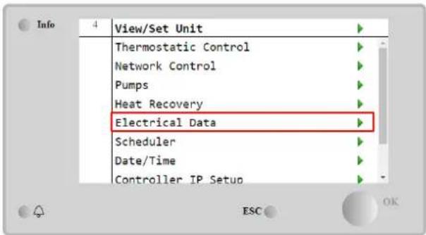
4.11 Electrical Data
Unit controller returns main electrical values read by the energy meter Nemo D4-L or Nemo D4-Le. All data are collected in the menu Electrical Data.
Main Page → View/Set Unit → Electrical Data
text_image
View/Set Unit Thermostatic Control Network Control Pumps Heat Recovery Electrical Data Scheduler Date/Time Controller IP Setup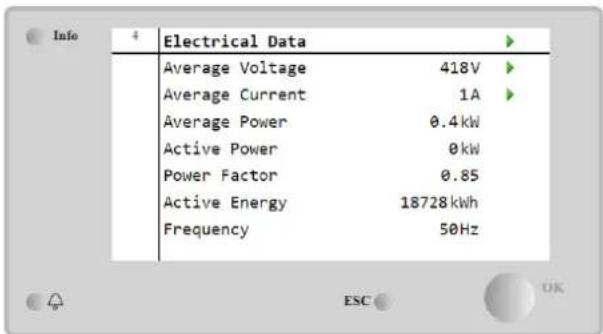
text_image
Info 4 Electrical Data Average Voltage 418V Average Current 1A Average Power 0.4kW Active Power 0kW Power Factor 0.85 Active Energy 18728kWh Frequency 50Hz| Parameter | Description |
| Average Voltage | Returns the average of the three chained voltages and links to the Voltage Data page |
| Average Current | Returns the current average and links to the Current Data page |
| Average Power | Returns the average power |
| Active Power | Returns the active power |
| Power Factor | Returns the power factor |
| Active Energy | Returns the active energy |
| Frequency | Returns the active frequency |
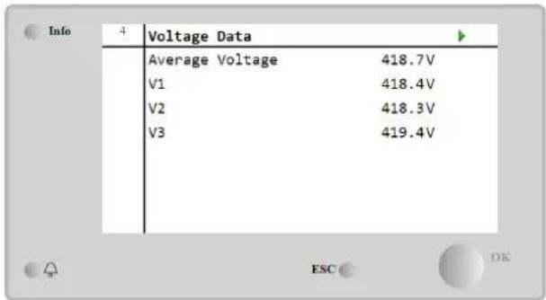
text_image
Info 4 Voltage Data Average Voltage 418.7V V1 418.4V V2 418.3V V3 419.4V| 1 | Current Data | |
| Average Current | 49.5A | |
| I1 | 49.3A | |
| I2 | 49.2A | |
| I3 | 49.9A |
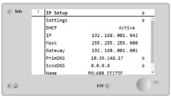
4.12 Controller IP Setup
The Controller IP Setup page is located at the path Main Menu → View/Set Unit → Controller IP Setup.

text_image
Info 4 View/Set Unit Thermostatic Control Network Control Pumps Power Conservation Scheduler Date/Time Controller IP Setup Daikin On Site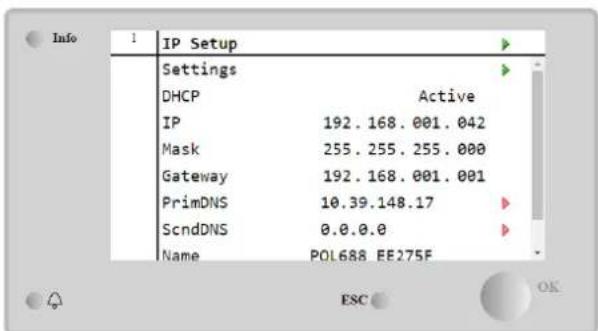
text_image
Info IP Setup Settings DHCP Active IP 192.168.001.042 Mask 255.255.255.000 Gateway 192.168.001.001 PrimDNS 10.39.148.17 ScndDNS 0.0.0.0 Name POL688 EE275FAll of the information about current MT4 IP Network settings is reported in this page, as shown in the following table:
| Parameter | Range | Description |
| DHCP | Active | The DHCP option is enabled. |
| Passive | The DHCP option is disabled. | |
| IP | xxx.xxx.xxx.xxx | The current IP address |
| Mask | xxx.xxx.xxx.xxx | The current Subnet Mask address. |
| Gateway | xxx.xxx.xxx.xxx | The current Gateway address. |
| PrimDNS | xxx.xxx.xxx.xxx | The current Primary DNS address. |
| ScndDNS | xxx.xxx.xxx.xxx | The current Secondary DNS address. |
| Device | POLxxx_xxxxxxx | The Host Name of the MT4 controller. |
| MAC | XX-XX-XX-XX-XX-XX | The MAC address of the MT4 controller. |
In order to modify the MT4 IP Network configuration, do the following operations:
- access the Settings menu
- set the DHCP option to Passive
- modify the IP, Mask, Gateway, PrimDNS and ScndDNS addresses, if needed, taking care of the current network settings
- set Apply changes parameter to Yes to save the configuration and restart the MT4 controller.
text_image
Info 1 IP Setup Settings DHCP Active IP 192.168.001.042 Mask 255.255.255.000 Gateway 192.168.001.001 PrimDNS 10.39.148.17 ScndDNS 0.0.0.0 Name POL688 EE275F ESC OK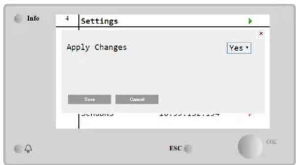
text_image
Info 4 Settings Apply Changes Yes * Save Cancel Settings 10:25:196:197 ESC OSThe default internet configuration is:
| Parameter | Default Value |
| IP | 192.168.1.42 |
| Mask | 255.255.255.0 |
| Gateway | 192.168.1.1 |
| PrimDNS | 0.0.0.0 |
| ScndDNS | 0.0.0.0 |
Note that if the DHCP is set to On and the MT4 internet configurations shows the following parameter values
| Parameter | Value |
| IP | 169.254.252.246 |
| Mask | 255.255.0.0 |
| Gateway | 0.0.0.0 |
| PrimDNS | 0.0.0.0 |
| ScndDNS | 0.0.0.0 |
then an internet connection problem has occurred (probably due to a physical problem, like the Ethernet cable breaking).
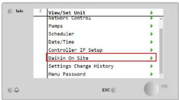
4.13 Daikin On Site
The Daikin on Site(DoS) page can be accessed navigating through Main Menu □ View/Set Unit □ Daikin On Site.
text_image
Info 2 View/Set Unit Network Control Pumps Scheduler Date/Time Controller IP Setup Daikin On Site Settings Change History Menu Password ESC OK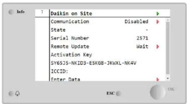
text_image
Daikin on Site Communication Disabled State - Serial Number 2571 Remote Update Wait Activation Key SY65J5-NKID3-E5KGB-JKWXL-NK4V ICCID: Enter DataIn order to use the DoS utility, the customer has to communicate the Serial Number to Daikin company and subscribe to the DoS service. Then, from this page, it is possible to:
- Start/Stop the DoS connectivity
- Check the connection status to DoS service
- Enable/Disable the remote update option
according to the parameters shown into the table below.
| Parameter | Range | Description |
| Comm Start | DisabledEnabled | Stop the connection to DoSStart the connection to DoS |
| Comm State | - | Connection to DoS is off |
| IPErr | Connection to DoS cannot be established | |
| Connected | Connection to DoS is established and working | |
| Remote Update | Wait | The Remote update is not allowed even the request is started from DOS |
| Yes | Enable the Remote update option | |
| No | Disable the Remote update option |
Among all the services provided by DoS, the Remote Update option allows to remotely update the software currently running on the PLC controller, avoiding an in-situ intervention of maintenance personnel. To this purpose, just set the Remote Update parameter to Yes. Otherwise, keep the parameter set to Wait or Disable.

For a successful remote software update, local service support is required, and a strong internet connection must be guaranteed.
In the unlikely event of PLC replacement, the DoS connectivity can be switched from the old PLC to the new one just communicating the current Activation Key to Daikin company.
4.14 Heat Recovery
The unit controller can handle a total or partial heat recovery option.
The heat recovery is enabled through the Q8 switch installed in the electrical panel.
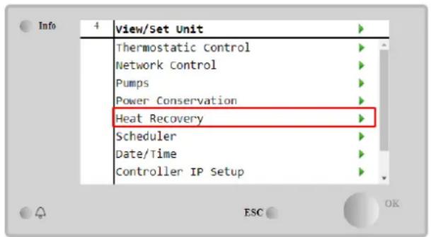
Some settings need to be properly set in order to match the specific plant requirements, going in Main Page→View/Set Unit→Heat Recovery.
text_image
View/Set Unit Thermostatic Control Network Control Pumps Power Conservation Heat Recovery Scheduler Date/Time Controller IP Setup
text_image
Info 4 Heat Recovery HR State Recirculation HR LWT 0.0°C HR EWT 0.0°C HR EWT Sp 40.0°C HR EWT Dif 2.0°C HR Lock Limit 25.0°C HR Delta Sp 5.0°C HR 3-Way Valve 0.0%| Parameter | Range | Description |
| HR State | Off | Heat recovery is disabled |
| Recirculation | Heat recovery pump is running, but chiller fan is not regulating the heat recovery water temperature | |
| Regulation | Heat recovery pump is running and chiller fans are regulating the heat recovery water temperature | |
| HR LWT | Heat recovery leaving water temperature | |
| HR EWT | Heat recovery entering water temperature | |
| HR EWT Sp | Heat recovery entering water temperature setpoint value | |
| HR EWT Dif | Heat recovery | |
| HR Lock Limit | ||
| HR Delta Sp | ||
| HR 3-Way Valve | Heat recovery 3-way valve opening percentage | |
| HR Pumps | Heat recovery pump state | |
| HR Pump Hours | Heat recovery pump running hours | |
| HR C1 Enable | Heat recovery enable on circuit 1 | |
| HR C2 Enable | Heat recovery enable on circuit 2 |
In case unit control source is "Network", to enable heat recovery functionality following conditions must be true:
- Enable the "HR C1 or C2 Enable" parameter in the Heat recovery page.
- Enable BMS register: Heat Recovery - Enable Setpoint
4.15 Rapid Restart
This chiller can activate a Rapid Restart (optional) sequence in reaction to a power failure. This option allows the unit to restore the load it had before the power failure in less time, reducing the standard cycle timer.
In order to Enable the Rapid Restart functionality, the customer must set to Yes the "Rapid Restart" parameter in the Rapid Restart page.
The feature is configured in the factory.
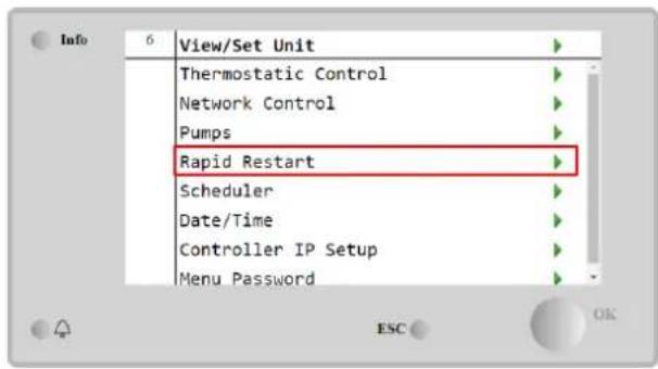
The 'Rapid Restart' page can be accessed navigating through Main Menu → View/Set Unit → Rapid Restart.
text_image
Info 6 View/Set Unit Thermostatic Control Network Control Pumps Rapid Restart Scheduler Date/Time Controller IP Setup Menu Password ESC OK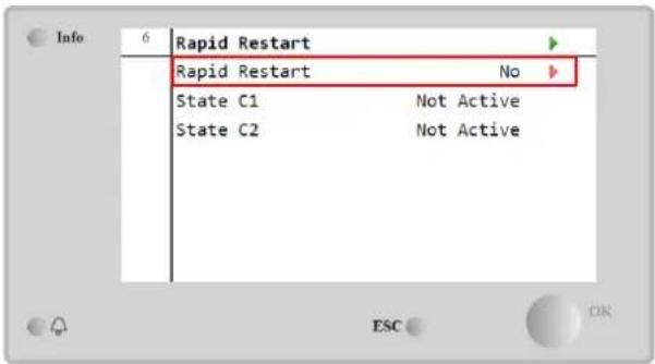
text_image
Info 6 Rapid Restart Rapid Restart No State C1 Not Active State C2 Not ActiveThe "State C1/2" represents the actual state of the Rapid Restart procedure for each circuit.
Rapid restart is activated under the following conditions:
• The power failure exists for up to 180 seconds
• The unit and circuit switches are ON
- No unit or circuit alarms exist
• The unit has been running in the normal Run state
• The BMS Circuit Mode setpoint is set to Auto when the control source is Network
- The ELWT isn't lower than the "ELWT Setpoint + StgUpDT"
- The ELWT is greater than the "ELWT Setpoint + NomEvapDT*Par_RpdRst", where Par_RpdRst is a parameter that can be modified
If the power failure is more than 180 seconds, the unit will start based on the standard cycle timer without Rapid Restart. After the power restart, the timers that are used during the Rapid Restart procedure are:
| Parameter | Timer |
| Pump On | 14s |
| 1st Compr On | 30s |
| Full Load (6 Compr) | 180s |
4.16 FreeCooling (Cooling Only)
The FreeCooling page can be accessed navigating through Main Menu → View/Set Unit → FreeCooling.

text_image
Info 4 View/Set Unit Thermostatic Control Free Cooling Network Control Pumps Scheduler Date/Time Controller IP Setup Daikin On Site ESC OK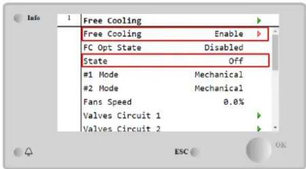
text_image
Info 1 Free Cooling Free Cooling Enable FC Opt State Disabled State Off #1 Mode Mechanical #2 Mode Mechanical Fans Speed 0.0% Valves Circuit 1 Valves Circuit 2| Parameter | Range | Description |
| FC OPT State | Disable | The Option is not enabled with all the inputs necessary, or cannot run because thermodynamics issues |
| Enable | The Option is correctly enabled | |
| State | off | Unit's State in Off |
| Free Cooling | Unit State in Free Cooling mode, both Circuits run in FreeCooling | |
| Mixed | Unit State in Mixed mode, one Circuit run in FreeCooling and the second run Mechanical mode | |
| Mechanical | Unit State in Mechanical mode, both Circuits run in Mechanical | |
| #x Mode | Mechanical | The Circuit x is running in Mechanical mode |
| FreeCooling | The Circuit x is running in FreeCooling mode | |
| Fans Speed | 0-100% | Percentage of fans speed controlled by FreeCooling |
| Command VA | Open | The opening output from the controller for the VA valve |
| Closed | The closing output from the controller for the VA valve | |
| Valve A Open | True | The Valve A is opened |
| False | The Valve A is NOT opened | |
| Valve A Closed | True | The Valve A is closed |
| False | The Valve A is NOT closed |
In order Enable the FreeCooling functionality, the customer must set to Enable the "Free Cooling" parameter in the FreeCooling page. The same parameter can be accessed on the Main Menu → Unit Enable:
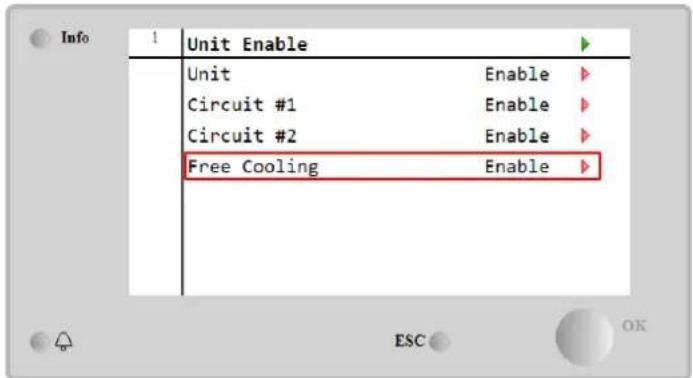
text_image
Info 1 Unit Enable Unit Enable Circuit #1 Enable Circuit #2 Enable Free Cooling EnableIn the FreeCooling page, from View/Set Unit, the customer can visualize also some useful information, as:
- “#1 Mode” and “#2 Mode”: The operating mode of each circuit;
- "State": The operating mode of the entire unit.

text_image
Info 4 Free Cooling #1 Mode Mechanical #2 Mode Mechanical Fans Speed 20.0 % Valves Circuit 1 Valves Circuit 2 Command VA Open Valve A Open True Valve A Closed TrueIn this page is possible to navigate in the pages "valves circuit 1" and "valves circuit 2", and both contain:

text_image
Info 4 Free Cooling C1 State Off Command V1 Closed Command V3 Closed Command VB Open V1Open+V3Closed False V1Closed+V3Open False Valve B Open True Valve B Closed TrueFigure 1 Valves Circuit 1
| Parameter | Range | Description |
| State | Off | The Circuit is in Off State |
| Switching | The Circuit is switching the valve in FreeCooling mode | |
| Regulation | The Circuit is running in FreeCooling and is regulating the Fan | |
| Pumpdown | The Circuit is in FreeCooling Pumpdown procedure | |
| Command V1 | Open | The opening output control from the controller for the V1 valve |
| Closed | The closing output control from the controller for the V1 valve | |
| V1open+V3Closed | True | The Valve V1 is opened AND the Valve V3 is closed |
| False | The Valve V1 is NOT opened AND/OR the Valve V3 is NOT closed | |
| V1Closed+V30pen | True | The Valve V1 is closed AND the Valve V3 is opened |
| False | The Valve V1 is NOT closed AND/OR the Valve V3 is NOT opened | |
| Command VA | Open | The opening output control from the controller for the VA valve |
| Closed | The closing output control from the controller for the VA valve | |
| Valve B Open | True | The Valve B is opened |
| False | The Valve B is NOT opened | |
| Valve B Closed | True | The Valve B is closed |
| False | The Valve B is NOT closed |
4.16.1 FreeCooling Switch
FreeCooling On/Off can be managed by the user using the selector SFC, placed in the electrical panel, which can switch between two positions: 0 - 1.
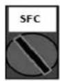
0
FreeCooling is disabled.

1
FreeCooling is enabled.
In order to enable the Unit to run in Free Cooling mode, both the FreeCooling Switch and the "Free Cooling" parameter, refer to 4.15, must be changed in the proper state.
4.16.2 Network On/Off
FreeCooling On/Off can be managed also with serial protocol, if the unit controller is equipped with one or more communication modules (BACNet, Modbus or LON). In order to control the unit over the network, follow below instructions:
- SFC selector = 1 (refer to 4.16.1)
- FreeCooling Enable = Enable (refer to 4.16)
- Control Source = Network (refer to 4.5)
- Close the contact Local/Network Switch (refer to 4.5), when required!
4.17 Collective Housing (Changeover Function, Heat Pump only)
It is requested the introduction of a feature that allows the automatic change of the operating mode of the unit, between heat-pump and chiller, depending on the temperature value read by a probe, that can be called "Changeover Probe", placed in the plant.
The scope of the Changeover function is to maintain the water temperature inside a specific range, desired for the plant, for example between 30^ C max and 20^ C minimum. If this temperature goes above 30^ C, the unit must change its operating mode in Cool, and cool the water under that value; the same if the temperature goes below 20^ C the unit must turn into Heat Pump in order to heat the water in the loop.
The thermoregulation logic follows the standard one on the ELWT probe, with also the StageUp, StageDn, StartUp and StopDn temperatures. But, for the Changeover function the software will look at the Changeover probe, to change the operating mode of the unit.
Called COWT = Changeover Water Temperature.
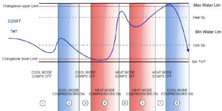
line
| Condition | Changeover Upper Limit | Changeover Lower Limit | | --------- | ---------------------- | ---------------------- | | COOL MODE COMPS OFF | Max Water Lim | Min TWT | | COOL MODE COMPRESSORS ON | Max Water Lim | Min TWT | | COOL MODE COMPS OFF | Max Water Lim | Min TWT | | HEAT MODE COMPRESSORS ON | Max Water Lim | Min TWT | | HEAT MODE COMPS OFF | Max Water Lim | Min TWT | | HEAT MODE COMPRESSORS ON | Max Water Lim | Min TWT | | COOL MODE COMPS OFF | Cool Sp | Min TWT | | COOL MODE COMPRESSORS ON | Cool Sp | Min TWT | | COOL MODE COMPS OFF | Cool Sp | Min TWT | | COOL MODE COMPRESSORS ON | Cool Sp | Min TWT | | COOL MODE COMPS OFF | Cool Sp | Min TWT | | COOL MODE COMPRESSORS ON | Cool Sp | Min TWT | | COOL MODE COMPS OFF | Cool Sp | Min TWT | | COOL MODE COMPRESSORS ON | Cool Sp | Min TWT | | Cools MODE COMPS OFF | Cool Sp | Min TWT | | Cools MODE COMPRESSORS ON | Cool Sp | Min TWT | | Cools MODE COMPS OFF | Cool Sp | Min TWT | | Cools MODE COMPRESSORS ON | Cool Sp | Min TWT | | Cools MODE COMPS OFF | Cool Sp | Min TWT | | Cools MODE COMPRESSORS ON | Cool Sp | Min TWT | | Cools MODE COMPS OFF | Cool Sp | Min TWT | | Cools MODE COMPRESSORS ON | Coils Compressor | Cool Sp | | Cools MODE COMPRESSORS ON | Coils Compressor | Cool Sp | | Cools MODE COMPRESSORS ON | Coils Compressor | Cool Sp | | Cools MODE COMPRESSORS ON | Coils Compressor | Cool Sp | | Cools MODE COMPRESSORS ON | Coils Compressor | Cool Sp | | Cools MODE COMPRESSORS ON | Coils Compressor | Cool Sp | | Cools MODE COMPRESSORS ON | Coils Compressor (Max Water Lim) | Cool Sp | | Cools MODE COMPRESSORS ON | Coils Compressor (Max Water Lim) | Cool Sp | | Cools MODE COMPRESSORS ON | Coils Compressor (Max Water Lim) | Cool Sp | | Cools MODE COMPRESSORS ON | Coils Compressor (Max Water Lim) | Cool Sp | | Cools Mode Compressors Off | Max Water Lim | Cool Sp | | Cools Mode Compressors Off | Max Water Lim | Cool Sp | | Cools Mode Compressors Off | Max Water Lim | Cool Sp | | Cools Mode Compressors Off | Max Water Lim | Cool Sp | | Cools Mode Compressors Off | Max Water Lim | Cool Sp | | Cools Mode Compressors Off | Max Water Lim | Cool Sp | | Cools Mode Compressors Off | Max Water Lim | Cool Sp |In order to maintain the normal logic of thermoregulation, in phases 1-2-3 the value of Start-Up permits the chiller to turn on in cool mode and cool the water till the Shut-dn temperature, where the unit shuts off the compressor and wait the load to turn on again.
Then, if the COWT < ChangeoverLowerLimit, the unit switches its operating mode into heat pump and heat the water up to Shut-Dn temperature Heat (Heat Sp + ShutDnDt), as in the phase 4. For thermoregulation, the unit switched to off and wait till the water goes below StartUp HeatValue to turn on again the compressor, as in phase 6.
Table below reports all parameters available in Collective Housing menu when Collective Hsng option is enabled.
HMI Path: Main Menu → View/Set Unit → Collective Hsng

text_image
Info 1 View/Set Unit Thermostatic Control Network Control Pumps Collective Hsng Scheduler Date/Time Controller IP Setup Daikin On Site ESC OK Info 1 Collective Housing CollectiveHsng En Yes CngOver Upper Lim 28.5°C CngOver Lower Lim 20.0°C WaterLow Lim 20.0°C WaterHigh Lim 30.0°C Coll Hsng Sp 25.0°C ESC OK| Setpoint/Sub Menu | Default | Range | Description |
| CollectiveHsng En | No | No-Yes | Enabling the changeover option |
| CngOver Upper Lim | 28.0°C | See Figure a | Value for the Changeover Upper Limit, when the Unit switch to Cool |
| CngOver Lower Lim | 20.0°C | See Figure a | Value for the Changeover Lower Limit, when the Unit switch to Heat |
| WaterLow Lim | 20.0°C | Minimun water temperature that is allowed in the point where the changeover probes is placed | |
| WaterHigh Lim | 30.0°C | Maximum water temperature that is allowed in the point where the changeover probes is placed | |
| Coll Hsng Sp | 25.0°C | Setpoint that decided the starting condition of the unit when is switched ON, dependig on the COWT |
The Temperature of the sensor that managed the Changeover Function, is visible also in the Main Menu, with the name "Cng Over Temp".
4.18 Domestic Hot Water
This function can be used to alternate normal unit operation with generation of domestic hot water. During "DHW" operation the unit is stopped, the water circuit is deviated by a 3 way valve and unit started on again to heat up a tank, containing the domestic hot water, until a the setpoint temperature is reached. At this point unit is switched back to normal operation.
This function expects a proper plant configuration and unit settings, please refer to specific documentation.
"Domestic hot water" function can be enabled by following the path Main Menu → Commission Unit → Configuration → options and set the DHW Enable parameter to Yes.
Notice that DHW is not compatible with Pump Control Mode VPF, DT and On-Off, Collective Housing and Bivalent Operation.
Additional features dedicated to Heating application like leaving water temperature setpoint control target based on DHW tank's temperature to guarantee a proper delta between Heat Pump's LWT and water inside tank and the automatic secondary fixed speed for DHW water loop to guarantee proper flow in the DHW loop are available.
Domestic Hot Water parameters can be configured in Main Menu → view/Set Unit → Domestic Hot water
| Setpoint/Sub Menu | Default | Range | R/W | Description |
| DHW State | - | Disabled Start Switch To Regulation SwitchBack | R | DHW state of operation |
| DHW Setpoint | 45 °C | 0..70 °C | W | DHW setpoint request |
| DHW Start Db | 5 °C | 0..20 °C | W | DHW deadband for the request |
| DHW Delay | 30 min | 0..1440min | W | Delay for reactivation of the DHW after returning to the primary circuit |
| DHW Temperature | °C | R | DHW tank water temperature | |
| DHW 3WV State | Start Switch EndError | R | DHW 3WV state of operation | |
| DHW Alarm Code | 0..3 | R | DHW alarm code | |
| DHW 3wV Type | 2Fdbck | 2Fdbck Temporized | W | DHW type of 3WV |
| DHW 3wV Switch time | 300 s | 0...900 s | W | DHW 3WV temporized time of switching |
| DHW Max Time | 30 min | 0..1440min | W | DHW max time of regulation in secondary circuit |
| DHW Standby Mode | off | Off On | W | With standby mode On the 3WV is always connected in the secondary circuit. |
| DHW Remote En | off | Off On | W | DHW remote enable |
| DHW Lwt Ctrl Target | off | Off On | W | DHW lwt control target based on tank temperature |
| DHW Secondary FixSpd | off | Off On | W | DHW secondary fixed speed for DHW water loop to guarantee proper flow in the DHW loop. |
In case unit control source is "Network", to enable domestic hot water functionality following conditions must be true:
The Bivalent Operation function allows the unit to manage the activation of a boiler with enabling/disabling as a function of the climatic curve of the system, set on the UC in an identical manner to the curve of the system present in the boiler, and of the outside ambient temperature.
"Bivalent Operation" function can be enabled by following the path Main Menu → Commission Unit → Configuration → options and set the Bivalent Operation parameter to Yes.
| Setpoint/Sub Menu | Default | Range | R/W | Description |
| (Bivalent Ops En) | Off | Off/On | W | Allows bivalent operation mode to start. |
| (Tamb Design) | 0 | -20...60 | W | Defines design ambient temperature for the system. |
| (System Lwt Design) | 60 | 20...75 | W | Defines system leaving water temperature target for the system at design ambient temperature. |
| (System Lwt@20) | 30 | 20...75 | W | Defines system leaving water temperature target for the system at 20°C ambient temperature. |
| (Tcut-off) | 0 | -7...7 | W | Defines lower limit for bivalent operation under which only boiler is enabled. |
| (Tbivalent) | 7 | 0...20 | W | Defines higher limit for bivalent operation over which only heat-pump is enabled.Is it possible to have transition with boiler active even if OAT >Tambient. |
| (System DeltaT) | 10 | 0...50 | W | This parameter shall match the exact delta temperature drop due to system load. |
| (Boiler Delay) | 0 | 0...60 | W | Defines activation delay between heat-pump and boiler in bivalent operation OAT range. |
Additional feature dedicated to Bivalent operation like system leaving water temperature setpoint received by a remote control is possible to be enable by following the path Main Menu → Commission Unit → Configuration → Options and set the Biv Syst Lwt Ctrl parameter to Remote.
Moreover it's also possible configured the sensor type of the remote Lwt control, if 0-10 V or 4-20 mA.
Main Menu → Commission Unit → Configuration → Options
| Setpoint/Sub Menu | Default | Range | R/W | Description |
| Buv Syst Lwt Ctrl | Local | Local Remote | W | Defines the type of System Lwt control |
| Bivalent Sns Type | 0-10V | 0-10V 4-20mA | W | Defines the sensor type of the System Lwt remote control. |

Bivalent Operation plants
Due to the boiler capability to deliver water temperatures out of maximum unit envelope it's necessary to pay attention to water loop realization in order to guarantee entering temperatures inside the limit and use the heat pump safely and prevent any component damaging.
4.20 Software Options
For the EWYT model, the possibility to employ a set of software options has been added to the functionality of the chiller, in according with the new Microtech 4 installed on the Unit. The Software Options do not require any additional hardware and regard communication channels and the new energy functionalities.
During the commissioning the machine is delivered with the Option Set chosen by the customer; the Password inserted is permanent and depends on the Serial Machine Number and the Option Set selected.
In order to check the current Option Set:
Main MenuCommission Unit→Configuration→Software Options.

text_image
Name Refresh Show/Hide trend Logout Info 1 Configuration Unit Options Software Options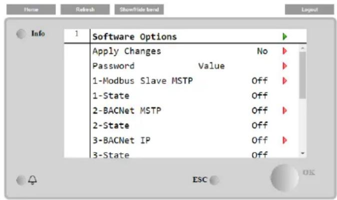
text_image
Home Refresh ShowSlide bend Layout Info 1 Software Options Apply Changes No Password Value 1-Modbus Slave MSTP Off 1-State Off 2-BACNet MSTP Off 2-State Off 3-BACNet IP Off 3-State Off ESC OK| Parameter | Description |
| Password | Writable by Interface/Web Interface |
| Option Name | Option Name |
| Option Status | Option is activated.Option is not activated |
The Current Password inserted activates the selected options.
4.20.1 Changing the Password for buying new Software Options
The Option Set and the Password are updated in the Factory. If the customer wants to change its Option Set, he needs to contact the Daikin Personnel and asks for a new password.
As soon as the new password is communicated, the follow steps allow the customer to change the Option Set by himself:
- Wait for the circuits are both OFF, then, from the Main Page, Main Menu→Unit Enable→Unit→Disable
- Go to Main Menu→Commission Unit→Configuration→Software Options
- Select the Options to Activate
- Insert the Password
- Wait for the States of the selected options going to On
- Apply Changes→Yes (it will reboot the controller)
The Password is changeable only if the machine is working in safe conditions: both the circuits are in the State Off.
4.20.2 Inserting the Password in a Spare Controller
If the Controller is broken and/or it needs to be replaced for any reason, the customer needs to configure the Option Set with a new Password.
If this replacement is scheduled, the customer can ask to Daikin Personnel for a new Password and repeat the steps in chapter 4.17.1.
If there is no enough time to ask for a Password to Daikin Personnel (ex. an expected failure of the controller), a set of Free Limited Password is provided, in order not to interrupt the machine's working.
These Passwords are free and visualized in:
Main Menu→Commission Unit→Configuration→Software Options→Temporary Passwords

text_image
Home Refresh Show/Side Icon Info 1 Software Options 4-Energy Monitoring Off 4-State Off 5-iCM Standard Off 5-State Off 6-iCM Advanced Off 6-State Off Temporary Passwords Apply Changes No ESC OK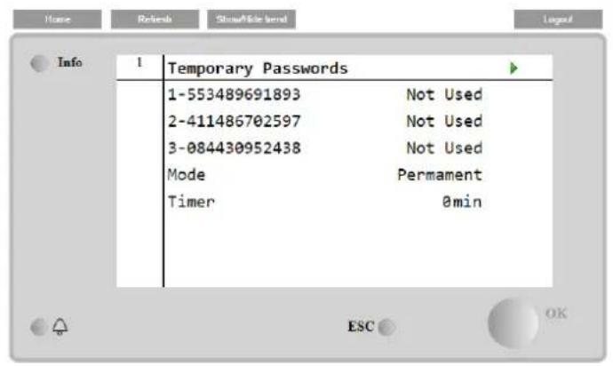
text_image
Home Relebs Showable level Logout Info 1 Temporary Passwords 1-553489691893 Not Used 2-411486702597 Not Used 3-084430952438 Not Used Mode Permanent Timer 0min ESC OKTheir Use is limited up to three months:
• 553489691893 – 3 Months Duration
• 411486702597 – 1 Month Duration
• 084430952438 – 1 Month Duration
It gives the customer the time enough to contact Daikin Service and insert a new unlimited password.
| Parameter | Specific Status | Description |
| 553489691893 | Activate the Option Set for 3 Months. | |
| 411486702597 | Activate the Option Set for 1 Month. | |
| 084430952438 | Activate the Option Set for 1 Month. | |
| Mode | Permanent | A permanent Password is inserted. Option set can be used for unlimited time. |
| Temporary | A temporary Password is inserted. Option set can be used depending on the password inserted. | |
| Timer | Last duration of the Option Set activated. Enabled only if the mode is Temporary |
The Password is changeable only if the machine is working in safe conditions: both the circuits are in the State Off.
4.20.3 Modbus MSTP Software Option
When the software option "Modbus MSTP" is activated and the controller is restarted, the communication protocol settings page can be accessed via the path:
Main Menu→Commission Unit→SW Modbus MSTP

text_image
Home Refresh Showhide bread Layout Info 1 Commission Unit Configuration Alarm Limits Manual Control Input/Output Sensors Calibration SW Modbus MSTP Scheduled MaintenanceThe values that can be set are the same as those found on the Modbus MSTP option page with the relative driver, and depend on the specific system where the unit is installed.
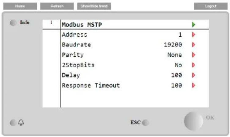
text_image
Info 1 Modbus MSTP Address 1 Baudrate 19200 Parity None 2StopBits No Delay 100 Response Timeout 100 ESC OK
To establish the connection, the RS485 port to use is the one on the T14 terminal of the MT4 controller.
4.20.4 BACNET MSTP
When the software option "BACNet MSTP" is activated and the controller is restarted, the communication protocol settings page can be accessed via the path:
Main Menu→Commission Unit→SW BACNet MSTP

text_image
Home Refresh ShowHide trend Layout Info 1 Commission Unit Configuration Alarm Limits Manual Control Input/Output Sensors Calibration SW BACNet MSTP Scheduled MaintenanceThe values that can be set are the same as those found on the BACNet MSTP option page with the relative driver, and depend on the specific system where the unit is installed.
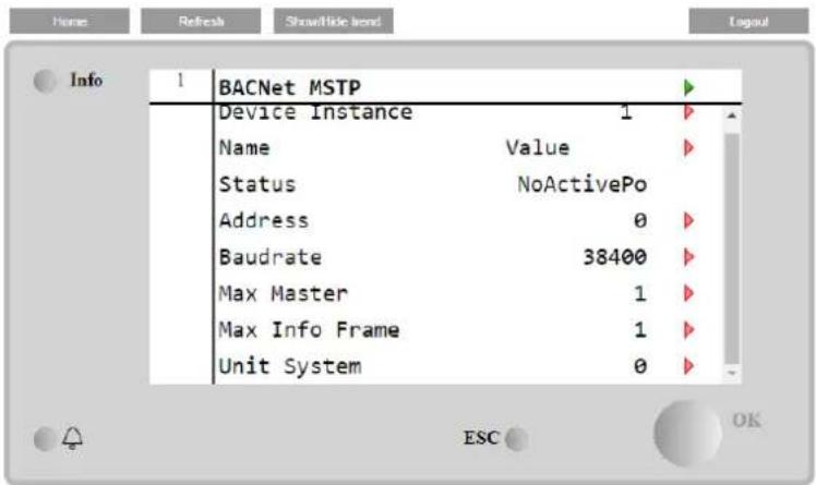
text_image
Info 1 BACNet MSTP Device Instance 1 Name Value Status NoActivePo Address 0 Baudrate 38400 Max Master 1 Max Info Frame 1 Unit System 0 ESC OK4.20.5 BACNET IP
When the software option "BACNet IP" is activated and the controller is restarted, the communication protocol settings page can be accessed via the path:
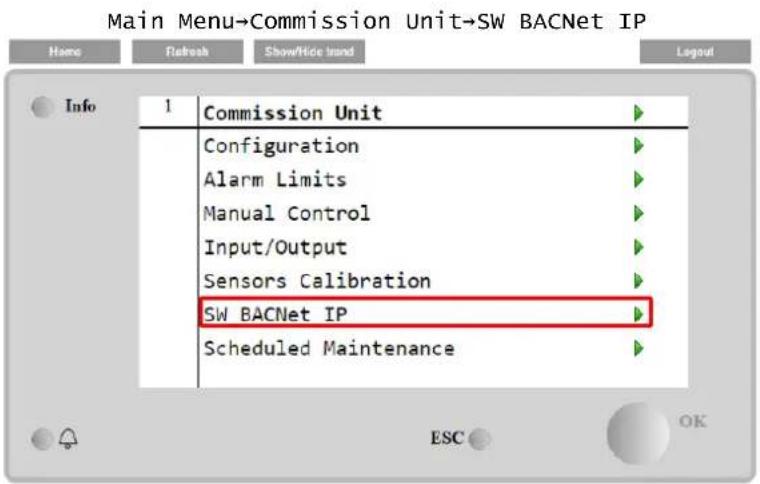
text_image
Main Menu→Commission Unit→SW BACNet IP Home Refresh ShowHide Trend Layout Info 1 Commission Unit Configuration Alarm Limits Manual Control Input/Output Sensors Calibration SW BACNet IP Scheduled MaintenanceThe values that can be set are the same as those found on the BACNet MSTP option page with the relative driver, and depend on the specific system where the unit is installed.
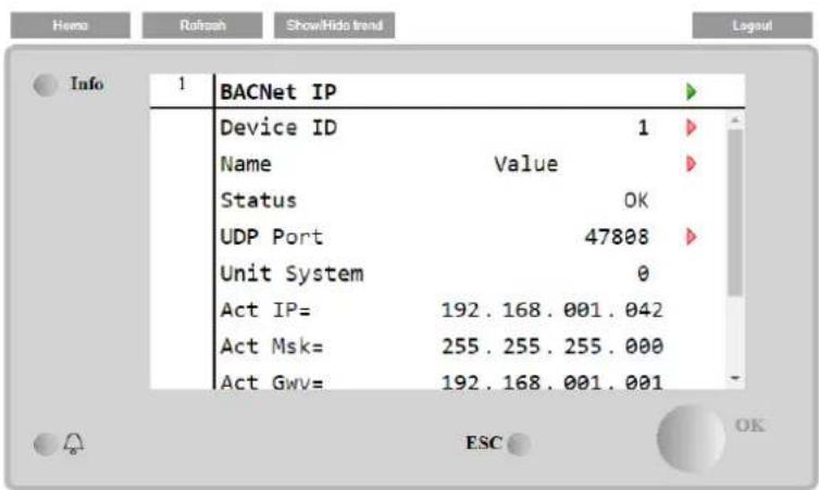
text_image
Info 1 BACNet IP Device ID 1 Name Value Status OK UDP Port 47808 Unit System 0 Act IP= 192.168.001.042 Act Msk= 255.255.255.000 Act Gwv= 192.168.001.001 ESC OKThe port for LAN connection to be used for BACNet IP communication is the T-IP Ethernet port, the same one used for remote control of the controller on the PC.
4.20.6 PERFORMANCE MONITORING
The Energy Monitoring is a software option not requiring any additional hardware. It can be activated in order to achieve an estimation of the instantaneous performances of the chiller in terms of:
• Cooling Capacity or Heating Capacity
- Power Input
• EER-COP in Cooling or Heating mode
An integrated estimation of these quantities is provided. Go to the page:
Main Menu→View / Set Unit→Energy Monitoring
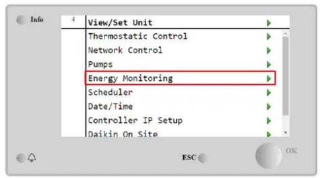
text_image
View/Set Unit Thermostatic Control Network Control Pumps Energy Monitoring Scheduler Date/Time Controller IP Setup Daikin On Site
text_image
Info 4 Energy Monitoring Power Input 0.0kW Cooling Capacity 0.0kW Heating Capacity 0.0kW EER 0.0 COP 0.0 Integrated Power Input 0.0MWh Integrated Cooling Cap ESC
text_image
Info 4 Power Input Circuit 1 0.0kW Circuit 2 0.0kW PI Pump 0.0kW ESC OK
text_image
Info 4 Cooling Capacity Circuit 1 0.0kW Circuit 2 0.0kW ESC OK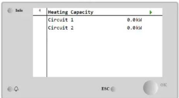
text_image
Info 4 Heating Capacity Circuit 1 0.0kW Circuit 2 0.0kW ESC OKThe BEG page can be accessed navigating through Main Menu → view/Set Unit → BEG
In BEG page as described above, it's possible to navigate and reset the internal database storing monitored energies of last 24 month.
| Page | Parameter | Range | Description | R/W | Psw |
| [28](BEG) | (EM Index) | 0..72 | The index selected defines the actual value displayed EM Value parameter.Cool Energy, Heat Energy e Power Input values are continuously added to actual month value. Last 24 energies value are available. In particular:1-8 = CoolEnergy [month 1-8]9-16 = ElectEnergy [month 1-8]17-24 = CoolEnergy [month 9-16]25-32 = ElectEnergy [month 9-16]33-40 = CoolEnergy [month 17-24]41-48 = ElectEnergy [month 17-24]49-64 =HeatEnergy [month 1-16]65-72 = HeatEnergy [month 17-24] | W | 1 |
| (EM Value) | 0.0...9999 | The value displayed match with the description of value associated to parameter “[28.00] (EM Index)". | R | 1 | |
| (EM Reset) | Off = PassiveOn = Active | Command reset for energy monitoring database. Resets all stored values to zero and sets actual date as reference for“month 1” values. After a reset month 1’s CoolEnergy, HeatEnergy and ElectEnergy will start to be updated depending on actual unite operations. | W | 1 |

First start
For correct initialization of the Energy Monitoring function, a Reset command shall be done immediately before the first start-up of the unit; otherwise, database will be populated with values that do not respect the expected order.

Date reference
A reset command set the reference date for database. Changing data backward will cause and invalid state and database won't be updated until reference date it reached again. Changing data forward will cause a non-reversible shift of reference date and every database's cell from old reference date to actual one will be filled with a 0-value.
4.20.7 Cascade
When the software option "Cascade System" is activated and the controller is restarted, the communication protocol settings page can be accessed via the path:
Main Menu→ Cascade
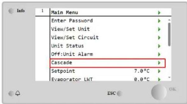
text_image
Info 1 Main Menu Enter Password View/Set Unit View/Set Circuit Unit Status Off:Unit Alarm Cascade Setpoint 7.0°C Evaporator LWT 0.0°C
text_image
Info 1 Cascade Data Settings Maintenance Configuration Version 1.00 ESC OKA Cascade system enable the heat production by water cooled unit supported by air cooled unit on evaporator side.

For more detailed information in Cascade menu, referring to the Cascade Management option.
4.21 Smart Grid Application
The SG page can be accessed navigating through Main Menu → View/Set Unit → SG
In case of Smart Grid operations (SG Box connected and smart grid functionalities enabled) actual state read by the gateway is available too, otherwise value is fixed at zero.
| (SG State) | 0...4 | The value represents the actual state sent by SG Gateway:0 = SG Disabled/SG Box Communication Error1 = (Bypass scheduler to force off)2 = (Normal Operation)3 = (Force Setpoint2)4 = (Bypass scheduler to enable) & (Force setpoint2) | R | 1 |

For further information eg: M/S Multi-Units case, configuration notes can be found in Smart Grid Ready Box Installation & Operating Manual D-EIOCP00301-23.
The UC protects the unit and the components from operating in abnormal conditions. Protections can be divided in preventions and alarms. Alarms can then be divided in pump-down and rapid stop alarms. Pump-down alarms are activated when the system or sub-system can perform a normal shutdown in spite of the abnormal running conditions. Rapid stop alarms are activated when the abnormal running conditions require an immediate stop of the whole system or sub-system to prevent potential damages.
The UC displays the active alarms in a dedicated page and keep an history of the last 50 entries divided between alarms and acknowledges occurred. Time and date for each alarm event and of each alarm acknowledge are stored.
The UC also stores alarm snapshot of each alarm occurred. Each item contains a snapshot of the running conditions right before the alarm has occurred. Different sets of snapshots are programmed corresponding to unit alarms and circuit alarms holding different information to help the failure diagnosis.
In the following sections it will also be indicated how each alarm can be cleared between local HMI, Network (by any of the high-level interfaces Modbus, Bacnet or Lon) or if the specific alarm will clear automatically.
5.1 Unit Alerts
All events reported in this section does not produce a unit stop, but only a visual information and an item in the alarm log.
5.1.1 BadLWTReset - Bad Leaving Water Temperature Reset Input
This alarm is generated when the Setpoint Reset option has been enabled and the input to the controller is out of the admitted range.
| Symptom | Cause | Solution |
| Unit status is Run.Bell icon is moving on controller's display.LWT Reset function cannot be used.String in the alarm list:BadLwTResetString in the alarm log:± BadLwTResetString in the alarm snapshotBadLwTReset | LWT reset input signal is out of range.For this warning out of range is considered to be a signal less than 3mA or more than 21mA. | Check for values of input signal to the unit controller. It has to be in the allowed mA range. |
| Check for electrical shielding of wirings. | ||
| Check for right value of the unit's controller output in case input signal is into allowed range. | ||
| Reset | ||
| Local HMINetworkAuto | ☐☐☑ | |
5.1.2 EnergyMeterComm - Energy Meter Communication Fail
This alarm is generated in case of communication problems with the energy meter.
| Symptom | Cause | Solution |
| Bell icon is moving on controller's display. String in the alarm list: EnergyMeterComm String in the alarm log: ± EnergyMtrComm String in the alarm snapshot EnergyMtrComm | Module has no power supply | Refer to the datasheet of the specific component to see if it is correctly powered. |
| Wrong cabling with the Unit Controller | Check if the polarity of the connections is respected. | |
| Modbus parameters not properly set | Referring to the datasheet of the specific component to see if the modbus parameters are set correctly: Address = 20 Baud Rate = 19200 kBs Parity = None Stop bits =1 | |
| Module is broken | Check if the display shows something and the power supply is present. | |
| Reset | ||
| Local HMI Network Auto | ☐ ☐ ☑ | |
5.1.3 SmartGridComm – Smart Grid Communication Fail
This alarm is generated in case of communication problems with the energy meter.
| Symptom | Cause | Solution |
| Bell icon is moving on controller's display.String in the alarm list: | Module has no power supply | Refer to the datasheet of the specific component to see if it is correctly powered. |
| SmartGridCommString in the alarm log:± SmartGridCommString in the alarm snapshotSmartGridComm | Wrong cabling with the Unit Controller | Check if the polarity of the connections is respected. |
| Modbus parameters not properly set | Referring to the datasheet of the specific component to see if the modbus parameters are set correctly. | |
| Module is broken | Check if the display shows something and the power supply is present. | |
| Reset | ||
| Local HMINetworkAuto | ☐☐☑ | |
5.1.4 EvapPump1Fault - Evaporator Pump #1 Failure
This alarm is generated if the pump is started but the flow switch is not able to close within the recirculate time. This can be a temporary condition or may be due to a broken flowswitch, the activation of circuit breakers, fuses or to a pump breakdown.
| Symptom | Cause | Solution |
| Unit could be ON.Bell icon is moving on controller's display.Backup pump is used or stop of all circuits in case of pump #2 failure.String in the alarm list:EvapPump1FaultString in the alarm log:± EvapPump1FaultString in the alarm snapshotEvapPump1Fault | Pump #1 may not be operating. | Check for problem in electrical wiring of the pump #1. |
| Check that electrical breaker of pump #1 is tripped. | ||
| If fuses are used to protect the pump, check the integrity of fuses. | ||
| Check for problem in wiring connection between pump starter and unit controller. | ||
| Check the water pump filter and the water circuit for obstructions. | ||
| Flow Switch doesn't operate properly | Check flow switch connection and calibration. | |
| Reset | ||
| Local HMINetworkAuto | ☑☑☐ | |
5.1.5 BadDemandLimit - Bad Demand Limit Input
This alarm is generated when the Demand Limit option has been enabled and the input to the controller is out of the admitted range.
| Symptom | Cause | Solution |
| Unit status is Run.Bell icon is moving on controller's display.Demand Limit function cannot be used.String in the alarm list:BadDemandLimitInputString in the alarm log:±BadDemandLimitInputString in the alarm snapshotBadDemandLimitInput | Demand limit input out of range. For this warning out of range is considered to be a signal less than 3mA or more than 21mA. | Check for values of input signal to the unit controller. It has to be in the allowed mA range. |
| Check for electrical shielding of wirings. | ||
| Check for right value of the unit's controller output in case input signal is into allowed range. | ||
| Reset | Notes | |
| Local HMINetworkAuto | ☐☐☑ | Automatically clears when the signal returns in the allowed range. |
5.1.6 EvapPump2Fault - Evaporator Pump #2 Failure
This alarm is generated if the pump is started but the flow switch is not able to close within the recirculate time. This can be a temporary condition or may be due to a broken flowswitch, the activation of circuit breakers, fuses or to a pump breakdown.
| Symptom | Cause | Solution |
| Unit could be ON.Bell icon is moving on controller's display. | Pump #2 may not be operating. | Check for problem in electrical wiring of the pump #2. |
| Check that electrical breaker of pump #2 is tripped.If fuses are used to protect the pump, check the integrity of fuses. | ||
| Backup pump is used or stop of all circuits in case of pump #1 failure. String in the alarm list:EvapPump2FaultString in the alarm log:± EvapPump2FaultString in the alarm snapshotEvapPump2Fault | ||
| Check for problem in wiring connection between pump starter and unit controller. | ||
| Check the water pump filter and the water circuit for obstructions. | ||
| Flow Switch doesn't operate properly | Check flow switch connection and calibration. | |
| Reset | ||
| Local HMINetworkAuto - Reset | ☑☑☐ | |
5.1.7 Switch Box Temperature sensor fault
This alarm is generated any time that the input resistance is out of an acceptable range.
| Symptom | Cause | Solution |
| Unit status is OnBell icon is moving on controller's display.Bell icon is moving on controller's display.String in the alarm list:SwitchBoxTempSenString in the alarm log:± SwitchBoxTempSenString in the alarm snapshotSwitchBoxTempSen | Sensor is broken. | Check for sensor integrity according table and allowed kOhm (kΩ) range. |
| Check correct sensors operation | ||
| Sensor is shorted. | Check if sensor is shorted with a resistance measurement. | |
| Sensor is not properly connected (open). | Check for absence of water or humidity on electrical contacts. | |
| Check for correct plug-in of the electrical connectors. | ||
| Check for correct sensors wiring also according electrical scheme. | ||
| Reset | Notes | |
| Local HMINetworkAuto | ☑☑☐ |
5.1.8 ExternalEvent - External Event
This alarm indicates that a device, whose operation is linked with this machine, is reporting a problem on the dedicated input.
| Symptom | Cause | Solution |
| Unit status is Run.Bell icon is moving on controller's display.String in the alarm list:External EventString in the alarm log:±ExternalEventString in the alarm snapshotExternalEvent | There is an external event that has caused the opening, for at least 5 seconds, of the digital input on the controller board. | Check for reasons of external event and if it can be a potential problem for a correct chiller operation. |
| Reset | ||
| Local HMINetworkAuto | ☐☐☑ | |
5.1.9 HeatRec EntWTempSen - Heat Recovery Entering Water Temperature sensor fault
This alarm is generated any time that the input resistance is out of an acceptable range.
| Symptom | Cause | Solution |
| Heat Recovery is OffBell icon is moving on controller's display.String in the alarm list:HeatRec EntwTempSenString in the alarm log:± HeatRec EntwTempSenString in the alarm snapshotHeatRec EntwTempSen | Sensor is broken. | Check for sensor integrity according table and allowed kOhm (kΩ) range. |
| Check correct sensors operation | ||
| Sensor is shorted. | Check if sensor is shorted with a resistance measurement. | |
| Sensor is not properly connected (open). | Check for absence of water or humidity on electrical contacts. | |
| Check for correct plug-in of the electrical connectors. | ||
| Check for correct sensors wiring also according electrical scheme. |
| Reset | |
| Local HMI | ☑ |
| Network | ☑ |
| Auto | ☑ |
5.1.10 HeatRec LvgWTempSen - Heat Recovery Leaving Water Temperature sensor fault
This alarm is generated any time that the input resistance is out of an acceptable range.
| Symptom | Cause | Solution |
| Heat Recovery is OffBell icon is moving on controller's display.String in the alarm list:HeatRec LvgwTempSenString in the alarm log:± HeatRec LvgwTempSenString in the alarm snapshotHeatRec LvgwTempSen | Sensor is broken. | Check for sensor integrity according table and allowed kOhm (kΩ) range. |
| Check correct sensors operation | ||
| Sensor is shorted. | Check if sensor is shorted with a resistance measurement. | |
| Sensor is not properly connected (open). | Check for absence of water or humidity on electrical contacts. | |
| Check for correct plug-in of the electrical connectors. | ||
| Check for correct sensors wiring also according electrical scheme. | ||
| Reset | ||
| Local HMINetworkAuto | ☑☑☑ | |
5.1.11 HeatRec FreezeAlm - Heat Recovery Water Freeze Protect alarm
This alarm is generated to indicate that the heat recovery water temperature (entering or leaving) has dropped below a safety limit. Control tries to protect the heat exchanger starting the pump and letting the water circulate.
| Symptom | Cause | Solution |
| Unit status is Off.All circuits are stopped immediately.Bell icon is moving on controller's display.String in the alarm list:HeatRec FreezeAlmString in the alarm log:± HeatRec FreezeAlmString in the alarm snapshotHeatRec FreezeAlm | Water flow too low. | Increase the water flow. |
| Inlet temperature to the heat recovery is too low. | Increase the inlet water temperature. | |
| Sensors readings (entering or leaving) are not properly calibrated | Check the water temperatures with a proper instrument and adjust the offsets | |
| Reset | ||
| Local HMINetworkAuto | ☑☐☐ | |
5.1.12 Option1BoardComm – Optional board 1 communication fail
This alarm is generated in case of communication problems with the AC module.
| Symptom | Cause | Solution |
| Unit status is Off.All circuits are stopped immediately.Bell icon is moving on controller's display.String in the alarm list:Option1BoardCommString in the alarm log:± Option1BoardCommString in the alarm snapshotOption1BoardComm | Module has no power supply | Check the power supply from the connector on the side of the module. |
| Check if LEDs are both green. | ||
| Check if the connector on the side is tightly inserted in the module | ||
| Module address is not properly set | Check if module's address is correct referring to the wiring diagram. | |
| Module is broken | Check if LED are on and both green.If BSP LED is solid red replace the module | |
| Check if power supply is ok but LEDs are both off. In this case replace the module | ||
| Reset | ||
| Local HMINetworkAuto | ☐☐☑ | |
5.1.13 Option2BoardComm - Optional board 2 communication fail
This alarm is generated in case of communication problems with the AC module.
| Symptom | Cause | Solution |
| Unit status is Off.All circuits are stopped immediately.Bell icon is moving on controller's display.String in the alarm list:Option2BoardCommString in the alarm log:± Option2BoardCommString in the alarm snapshotOption2BoardComm | Module has no power supply | Check the power supply from the connector on the side of the module. |
| Check if LEDs are both green. | ||
| Check if the connector on the side is tightly inserted in the module | ||
| Module address is not properly set | Check if module's address is correct referring to the wiring diagram. | |
| Module is broken | Check if LED are on and both green.If BSP LED is solid red replace the module | |
| Check if power supply is ok but LEDs are both off. In this case replace the module | ||
| Reset | ||
| Local HMINetworkAuto | ☐☐☑ | |
5.1.14 Option3BoardComm – Optional board 3 communication fail
This alarm is generated in case of communication problems with the AC module, related with the FreeCooling option.
| Symptom | Cause | Solution |
| Unit status is Off.All circuits are stopped immediately.Bell icon is moving on controller's display.String in the alarm list:Option3BoardCommString in the alarm log:± Option3BoardCommString in the alarm snapshotOption3BoardComm | Module has no power supply | Check the power supply from the connector on the side of the module. |
| Check if LEDs are both green. | ||
| Check if the connector on the side is tightly inserted in the module | ||
| Module address is not properly set | Check if module's address is correct referring to the wiring diagram. | |
| Module is broken | Check if LED are on and both green.If BSP LED is solid red replace the module | |
| Check if power supply is ok but LEDs are both off. In this case replace the module | ||
| Reset | ||
| Local HMINetworkAuto | ☐☐☑ | |
5.1.15 EvapPDSen – Evaporator Pressure Drop sensor fault
This alarm indicates that the evaporator pressure drop transducer is not operating properly. This transducer is used only with Pump Control VPF.
| Symptom | Cause | Solution |
| Pump speed is set with Backup value.Bell icon is moving on controller's display.String in the alarm list:EvapPDSenString in the alarm log:± EvapPDSenString in the alarm snapshotEvapPDSen | Sensor is broken. | Check for sensor integrity.Check correct sensors operation according information about mVolt (mV) range related to pressure values in kPa. |
| Sensor is shorted. | Check if sensor is shorted with a resistance measurement. | |
| Sensor is not properly connected (open). | Check for correct installation of the sensor on refrigerant circuit pipe. The transducer must be able to sense the pressure through the valve's needle. | |
| Check for absence of water or humidity on sensor electrical contacts. | ||
| Check for correct plug-in of the electrical connectors. | ||
| Check for correct sensors wiring also according electrical scheme. | ||
| Reset | ||
| Local HMINetwork | ☑☑☑ | |
| Auto |
5.1.16 LoadPDSen - Load Pressure Drop sensor fault
This alarm indicates that the loa pressure drop transducer is not operating properly. This transducer is used only with Pump Control VPF.
| Symptom | Cause | Solution |
| Pump speed is set with Backup value.Bell icon is moving on controller's display.String in the alarm list:LoadPDSenString in the alarm log:± LoadPDSenString in the alarm snapshotLoadPDSen | Sensor is broken. | Check for sensor integrity.Check correct sensors operation according information about mVolt (mV) range related to pressure values in kPa. |
| Sensor is shorted. | Check if sensor is shorted with a resistance measurement. | |
| Sensor is not properly connected (open). | Check for correct installation of the sensor on refrigerant circuit pipe. The transducer must be able to sense the pressure through the valve's needle. | |
| Check for absence of water or humidity on sensor electrical contacts. | ||
| Check for correct plug-in of the electrical connectors. | ||
| Check for correct sensors wiring also according electrical scheme. | ||
| Reset | ||
| Local HMINetworkAuto | ☑☑☑ | |
5.1.17 DHW WaterTmpSen – Domestic Hot Water Temperature sensor fault (Heat Pump Only)
This alarm is generated any time that the input resistance is out of an acceptable range. This sensor is present only when the Domestic Hot Water option is enabled.
| Symptom | Cause | Solution |
| Unit status is Off.Bell icon is moving on controller's display.String in the alarm list:DHW WaterTmpSenString in the alarm log:± DHW WaterTmpSenString in the alarm snapshotDHW WaterTmpSen | Sensor is broken. | Check for sensor integrity according table and allowed kOhm (kΩ) range. |
| Check correct sensors operation | ||
| Sensor is shorted. | Check if sensor is shorted with a resistance measurement. | |
| Sensor is not properly connected (open). | Check for absence of water or humidity on electrical contacts. | |
| Check for correct plug-in of the electrical connectors. | ||
| Check for correct sensors wiring also according electrical scheme. | ||
| Reset | ||
| Local HMINetworkAuto | ☑☑☑ | |
5.1.18 BivSystLwtRemAlm-Bivalent System LWT Remote Alarm (Heat Pump Only)
This alarm is generated when the Bivalent option has been enabled and the input to the controller is out of the admitted range.
| Symptom | Cause | Solution |
| Unit status is Run.Bell icon is moving on controller's display.String in the alarm list:BivSystLwtRemAlmString in the alarm log:± BivSystLwtRemAlmString in the alarm snapshotBivSystLwtRemAlm | Demand limit input out of range. For this warning out of range is considered to be a signal less than 2mA (or -1V) or more than 22mA (or 11V) | Check for values of input signal to the unit controller. It has to be in the allowed mA range. |
| Check for electrical shielding of wirings. | ||
| Check for right value of the unit's controller output in case input signal is into allowed range. | ||
| Reset | Notes | |
| Local HMINetworkAuto | □□☑ | Automatically clears when the signal returns in the allowed range. |
5.2 Unit Pumpdown Alarms
All alarms reported in this section produce a unit stop performed following normal pumpdown procedure.
5.2.1 UnitOff EvpEntWTempSen - Evaporator Entering Water Temperature (EWT) sensor fault
This alarm is generated any time the input resistance is out of an acceptable range.
| Symptom | Cause | Solution |
| Unit status is Off.All circuits are stopped with a normal shutdown procedure.Bell icon is moving on controller's display.String in the alarm list:UnitOff EvpEntwTempSenString in the alarm log:± UnitOff EvpEntwTempSenString in the alarm snapshotUnitOff EvpEntwTempSen | Sensor is broken. | Check for sensor integrity according table and allowed kOhm (kΩ) range. |
| Check correct sensors operation | ||
| Sensor is shorted. | Check if sensor is shorted with a resistance measurement. | |
| Sensor is not properly connected (open). | Check for absence of water or humidity on electrical contacts. | |
| Check for correct plug-in of the electrical connectors. | ||
| Check for correct sensors wiring also according electrical scheme. | ||
| Reset | ||
| Local HMINetworkAuto | ☑☑☑ | |
5.2.2 UnitOffLvgEntWTempSen - Evaporator Leaving Water Temperature (LWT) sensor fault
This alarm is generated any time that the input resistance is out of an acceptable range.
| Symptom | Cause | Solution |
| Unit status is Off.All circuits are stopped with a normal shutdown procedure.Bell icon is moving on controller's display.String in the alarm list:UnitOffLvgEntwTempSenString in the alarm log:± UnitOffLvgEntwTempSenString in the alarm snapshotUnitOffEvpLvgWTempSen | Sensor is broken. | Check for sensor integrity according table and allowed kOhm (kΩ) range. |
| Check correct sensors operation | ||
| Sensor is shorted. | Check if sensor is shorted with a resistance measurement. | |
| Sensor is not properly connected (open). | Check for absence of water or humidity on electrical contacts. | |
| Check for correct plug-in of the electrical connectors. | ||
| Check for correct sensors wiring also according electrical scheme. | ||
| Reset | ||
| Local HMINetworkAuto | ☑☑☑ | |
5.2.3 UnitOffAmbTempSen - Outside Air Temperature sensor fault
This alarm is generated any time the input resistance is out of an acceptable range.
| Symptom | Cause | Solution |
| Unit status is Off.All circuits are stopped with a normal shutdown procedure.Bell icon is moving on controller's display.String in the alarm list:UnitOffAmbTempSenString in the alarm log:± UnitOffAmbTempSenString in the alarm snapshotUnitOffAmbTempSen | Sensor is broken. | Check for sensor integrity. |
| Check correct sensors operation according table and allowed kOhm (kΩ) range. | ||
| Sensor is shorted. | Check if sensor is shorted with a resistance measurement. | |
| Sensor is not properly connected (open). | Check for absence of water or humidity on electrical contacts. | |
| Check for correct plug-in of the electrical connectors. | ||
| Check for correct sensors wiring also according electrical scheme. | ||
| Reset | ||
| Local HMINetworkAuto | ☑☑☑ | |
5.2.4 OAT: Lockout - Outside Air Temperature (OAT) Lockout (only in Cooling Mode)
This alarm prevents the unit to start if the outside air temperature is too low. Purpose is to prevent low pressure trips at startup. The limit depends on the fan regulation that is installed on the unit. By default this value is set to 10^ C.
| Symptom | Cause | Solution |
| Unit Status is OAT Lockout.All circuits are stopped with a normal shutdown procedure.Bell icon is moving on controller's display.String in the alarm list:StartInhbtAmbTempLoString in the alarm log:± StartInhbtAmbTempLoString in the alarm snapshotStartInhbtAmbTempLo | Outside ambient temperature is lower than value set into unit's controller. | Check the minimum outside ambient temperature value set into the unit's controller. |
| Check if this value is in accordance with chiller application, therefore check about the proper application and utilization of the chiller. | ||
| Improper operation of Outside Ambient Temperature sensor. | Check for proper operation of OAT sensor according information about kOhm (kΩ) range related to temperature values. | |
| Reset | Notes | |
| Local HMINetworkAuto | ☐☐☑ | It clears automatically with a 2.5°C of hysteresis. |
5.2.5 UnitOff CollHsngWTempSen – Collective Housing Water Temperature (LWT) sensor fault (Heat Pump Only) This alarm is generated any time that the input resistance is out of an acceptable range. This sensor is present only when the Collective Housing option is enabled, and when the plant hasn't an iCM or Master/Slave control.
| Symptom | Cause | Solution |
| Unit status is Off.All circuits are stopped with a normal shutdown procedure.Bell icon is moving on controller's display.String in the alarm list:Unitoff CollHsngwTempSenString in the alarm log:± Unitoff CollHsngwTempSenString in the alarm snapshotUnitoff CollHsngwTempSen | Sensor is broken. | Check for sensor integrity according table and allowed kOhm (kΩ) range. |
| Check correct sensors operation | ||
| Sensor is shorted. | Check if sensor is shorted with a resistance measurement. | |
| Sensor is not properly connected (open). | Check for absence of water or humidity on electrical contacts. | |
| Check for correct plug-in of the electrical connectors. | ||
| Check for correct sensors wiring also according electrical scheme. | ||
| Reset | ||
| Local HMINetworkAuto | ☑☑☑ | |
5.3 Unit Rapid Stop Alarms
All alarms reported in this section produce an instantaneous stop of the unit.
5.3.1 Power Failure - Power Failure (only for units with the UPS option)
This alarm is generated when the main power is Off and the unit controller is powered by the UPS.

Resolution of this fault requires a direct intervention on the power supply of this unit. Direct intervention on the power supply can cause electrocution, burns or even death. This action must be performed only by trained persons. In case of doubts contact your maintenance company.
| Symptom | Cause | Solution |
| Unit status is Off.All circuits are stopped immediately.Bell icon is moving on controller's display.String in the alarm list:Power FaultString in the alarm log:± Power FaultString in the alarm snapshotPower Fault | Loss of one phase. | Check voltage level on each of the phases. |
| Not correct sequence connection of L1,L2,L3. | Check sequence of L1, L2, L3 connections according indication on chiller's electrical scheme. | |
| Voltage level on the unit's panel is not in the allowed range (±10%). | Check that voltage level on each phases is into the allowed range that is indicated on the chiller label.Is important to check the voltage level on each phases not only with chiller not running, but mainly with chiller running from minimum capacity up to full load capacity. That's because voltage drop can occur from a certain unit cooling capacity level, or becauseof certain working condition (i.e. high values of OAT).In these cases the issue can be related with the sizing of power cables. | |
| There is a short-circuit on the unit. | Check for correct electrical isolation condition of each unit's circuit with a Megger tester. | |
| Reset | Notes | |
| Local HMI Network Auto | ☑☑ |
5.3.2 UnitOff EvapFreeze - Evaporator Water Temperature Low alarm
This alarm is generated to indicate that the water temperature (entering or leaving) has dropped below a safety limit.
Control tries to protect the heat exchanger starting the pump and letting the water circulate.
| Symptom | Cause | Solution |
| Unit status is Off.All circuits are stopped immediately.Bell icon is moving on controller's display.String in the alarm list:UnitOff EvapWaterTmpLowString in the alarm log:± UnitOff EvapWaterTmpLowString in the alarm snapshotUnitOff EvapWaterTmpLow | Water flow too low. | Increase the water flow. |
| Inlet temperature to the evaporator is too low. | Increase the inlet water temperature. | |
| Flow switch is not working or no water flow. | Check the flow switch and the water pump. | |
| Sensors readings (entering or leaving) are not properly calibrated. | Check the water temperatures with a proper instrument and adjust the offsets | |
| Wrong freeze limit setpoint. | The freeze limit has not been changed as a function of glycol percentage. | |
| Reset | ||
| Local HMINetworkAuto | ☑☐☑ | |
5.3.3 UnitOff ExternalAlarm - External alarm
This alarm is generated to indicate that an external device whose operation is linked with this unit operation. This external device could be a pump or an inverter.
| Symptom | Cause | Solution |
| Unit status is Off.All circuits are switched off with the normal shutdown procedure.Bell icon is moving on controller's display.String in the alarm list:UnitOff ExternalAlarmString in the alarm log:± UnitOff ExternalAlarmString in the alarm snapshotUnitOff ExternalAlarm | There is an external event that has caused the opening, for at least 5 seconds, of the port on the controller board. | Check causes of the external event or alarm. |
| Check electrical wiring from unit controller to the external equipment in case of any external events or alarms have been occurred. | ||
| Reset | ||
| Local HMINetworkAuto | ☐☐☑ | |
5.3.4 UnitOff PVM - PVM
This alarm is generated in case of problems with the power supply to the chiller.

Resolution of this fault requires a direct intervention on the power supply of this unit. Direct intervention on the power supply can cause electrocution, burns or even death. This action must be performed only by trained persons. In case of doubts contact your maintenance company.
| Symptom | Cause | Solution |
| Unit status is Off.All circuits are stopped immediately.Bell icon is moving on controller's display.String in the alarm list: | Loss of one phase. | Check voltage level on each of the phases. |
| Not correct sequence connection of L1, L2, L3. | Check sequence of L1, L2, L3 connections according indication on chiller's electrical scheme. | |
| Unitoff PVMString in the alarm log:± Unitoff PVMString in the alarm snapshotUnitoff PVM | Voltage level on the unit's panel is not in the allowed range (±10%). | Check that voltage level on each phases is into the allowed range that is indicated on the chiller label.Is important to check the voltage level on each phases not only with chiller not running, but mainly with chiller running from minimum capacity up to full load capacity. That's because voltage drop can occur from a certain unit cooling capacity level, or because of certain working condition (i.e. high values of OAT).In these cases the issue can be related with the sizing of power cables. |
| There is a short-circuit on the unit. | Check for correct electrical isolation condition of each unit's circuit with a Megger tester. | |
| Reset | ||
| Local HMINetworkAuto | ☐☐☑ | |
5.3.5 UnitOff EvapWaterFlow - Evaporator Water Flow Loss alarm
This alarm is generated in case of flow loss to the chiller to protect the machine against freezing.
| Symptom | Cause | Solution |
| Unit status is Off.All circuits are stopped immediately.Bell icon is moving on controller's display.String in the alarm list:UnitOff EvapWaterFlowString in the alarm log:± UnitOff EvapWaterFlowString in the alarm snapshotUnitOff EvapWaterFlow | No water flow sensed for 3 minutes continuously or water flow too low. | Check the water pump filler and the water circuit for obstructions. |
| Check the flow switch calibration and adapt to minimum water flow. | ||
| Check if pump impeller can rotate freely and has no damages. | ||
| Check pumps protection devices (circuit breakers, fuses, inverters, etc.) | ||
| Check if water filter is clogged. | ||
| Check flow switch connections. | ||
| Reset | ||
| Local HMINetworkAuto | ☑☑☐ | |
5.3.6 UnitOff EXVDriverComm - EXV Driver Extension Communication Error
This alarm is generated in case of communication problems with the EEXV module.
| Symptom | Cause | Solution |
| Unit status is Off.All circuits are stopped immediately.Bell icon is moving on controller's display.String in the alarm list:UnitOff EXVDriverCommString in the alarm log:± UnitOff EXVDriverCommString in the alarm snapshotUnitOff EXVDriverComm | Module has no power supply | Check the power supply from the connector on the side of the module. |
| Check if LEDs are both green. | ||
| Check if the connector on the side is tightly inserted in the module | ||
| Module address is not properly set | Check if module's address is correct referring to the wiring diagram. | |
| Module is broken | Check if LED are on and both green.If BSP LED is solid red replace the module | |
| Check if power supply is ok but LEDs are both off. In this case replace the module | ||
| Reset | ||
| Local HMINetworkAuto | ☑☑☐ | |
5.3.7 UnitOff Option4BoardComm – Optional board 4 communication fail
This alarm is generated in case of communication problems with the AC module.
| Symptom | Cause | Solution |
| Unit status is Off.All circuits are stopped immediately.Bell icon is moving on controller's display.String in the alarm list:Option4BoardCommString in the alarm log:± Option4BoardCommString in the alarm snapshotOption4BoardComm | Module has no power supply | Check the power supply from the connector on the side of the module. |
| Check if LEDs are both green. | ||
| Check if the connector on the side is tightly inserted in the module | ||
| Module address is not properly set | Check if module's address is correct referring to the wiring diagram. | |
| Module is broken | Check if LED are on and both green.If BSP LED is solid red replace the module | |
| Check if power supply is ok but LEDs are both off. In this case replace the module | ||
| Reset | ||
| Local HMINetworkAuto | ☐☐☑ | |
5.3.8 DHW 3WVAlarm – Domestic Hot Water 3 Way Valve Alarm (Heat pump only)
This alarm is generated if the 3WV for DHW is fault or damaged. The 3WV is not able to do the changeover to the secondary or primary loop. A 3WV fault can be related to connection/wiring issue or to component break up and are available only in temporized valve configuration.
| Symptom | Cause | Solution |
| Unit could be ON.All circuits are stopped immediately.Bell icon is moving on controller's display.String in the alarm list:DHw 3wVAlarmString in the alarm log:± DHw 3wVAlarmString in the alarm snapshotDHw 3wVAlarm | Errors in sensor wiring/connection | Check valve's cablingCheck 3WV. |
| Reset | ||
| Local HMINetworkAuto | ☑☑☐ | |
5.3.9 UnitOff WaterOverHeat- Water Over Temperature Alarm
This alarm is generated if the EWT for DHW is fault or damaged. The 3WV is not able to do the changeover to the secondary or primary loop. A 3WV fault can be related to connection/wiring issue or to component break up and are available only in temporized valve configuration.
| Symptom | Cause | Solution |
| Unit could be ON.All circuits are stopped immediately.Bell icon is moving on controller's display.String in the alarm list:Unitoff waterOverHeatString in the alarm log:± Unitoff waterOverHeatString in the alarm snapshotUnitoff waterOverHeat | Entering water temperature over unit envelope limit. | Check if Unit is working inside allowed envelope |
| Reset | ||
| Local HMINetworkAuto | ☑☑☐ | |
5.4 Circuit Events
5.4.1 Cx CompXStartFail – Compressor starting fail event
This event is generated to indicate that the compressor 'x' did not start correctly.
| Symptom | Cause | Solution |
| Compressor status is Off.If the compressor was the first to switch on, the circuit is switched off with the normal shutdown procedure. Otherwise, the circuit will run with the other compressor on.String in the event list:CmpXStartFailString in the event log:± CmpXStartFailString in the snapshotCmpXStartFail | Compressor is blocked. | Check for compressor integrity. |
| Check in test mode if the compressor starts manually and create Delta Pressure. | ||
| Compressor is broken. | Check for compressor integrity. | |
| Check for correct compressor wiring also according with electrical scheme. | ||
| Local HMI Network Auto | ||
5.4.2 Cx DischTempUnload – High Discharge Temperature Unload event
This event is generated to indicate that the circuit partially, shutting down a compressor, due to the high value of Discharge temperature detected. This is important for compressor reliability.
| Symptom | Cause | Solution |
| The Circuit reduces its capacity if the DischTmp > DischTmpUnload.If the compressor was the first to switch on, the circuit is switched off with the normal shutdown procedure. Otherwise, the circuit will run with the other compressor on.String in the event list:Cx DischTempUnloadString in the event log:± Cx DischTempUnloadString in the snapshotCx DischTempUnload | The circuit is working outside the compressor envelope. | Check the working conditions, if the unit is working inside the unit envelope, and if the expansion valve is working well. |
| One of the compressors is damaged. | Check if the compressors are working properly, in normal conditions and without noises. | |
| Local HMINetworkAuto | ||
5.4.3 Cx EvapPressUnload – Low Evaporator Pressure Unload event
This event is generated to indicate that the circuit partialized, shutting down a compressor, due to the low value of Evaporator pressure detected. This is important for compressor reliability.
| Symptom | Cause | Solution |
| The Circuit reduces its capacity if the EvapPr < EvapPressUnload.If only one compressor is running, the circuit will maintain its capacity. Otherwise, the circuit will shut down one compressor each X sec, till the evaporator pressure increase.String in the event list:Cx EvapPressUnloadString in the event log:± Cx EvapPressUnloadString in the snapshotCx EvapPressUnload | The circuit is working outside the compressor envelope. | Check if the EXV is working well. |
| Check the working conditions, if the unit is working inside the unit envelope, and if the expansion valve is working well. | ||
| The outside air temperature is too low (in heat mode). | Check if the unit is working correctly inside the unit envelope. | |
| The Circuit is near the Defrost request. | ||
| The leaving water temperature is too low (Cool Mode) | Check if the unit is working correctly inside the unit envelope. | |
| Local HMI Network Auto | ||
5.4.4 Cx CondPressUnload – High Condenser Pressure Unload event
This event is generated to indicate that the circuit partially, shutting down a compressor, due to the high value of Condensing pressure detected. This is important for compressor reliability.
| Symptom | Cause | Solution |
| The Circuit reduces its capacity if the CondPr >CondPressUnload.If only one compressor is running,the circuit will maintain its capacity.Otherwise, the circuit will shut downone compressor each X sec, till thecondenser pressure decrease.String in the event list:Cx CondPressUnloadString in the event log:± Cx CondpPressUnloadString in the snapshotCx CondPressUnload | The circuit is working outside thecompressor envelope. | Check for ice on evaporator (Heat mode). |
| Check the working conditions, if theunit is working inside the unitenvelope, and if the expansion valveis working well. | ||
| The outside air temperature is high (incool mode). | Check the correct functioning of thefans (in cool mode). | |
| The leaving water temperature is toohigh (Heat Mode) | Check if the unit is working correctlyinside the unit envelope. | |
| Local HMINetworkAuto | ||
5.4.5 Cx HighPressPd – High Pressure during Pumpdown event
This event is generated during a pumpdown procedure, to indicate that the condensing pressure goes above the unload value.
| Symptom | Cause | Solution |
| The Circuit stops the pumpdown procedure if the CondPr >CondPressUnload.String in the event list:Cx HighPressPdString in the event log:± Cx HighPressPdString in the snapshotCx HighPressPd | The pumpdown procedure was taking too long. | Check if the EXV is working well, and if it is fully close during pumpdown. |
| Check the working conditions, if the unit is working inside the unit envelope, and if the expansion valve is working well. | ||
| Local HMI Network Auto | ||
5.4.6 DischTmp CompxSenf - Discharge Temperature of compressor sensor fault
This alarm indicates that the discharge temperature sensor, put one for each compressor, is not operating properly. These sensors are placed with the Option "DLT Logic" enabled.
| Symptom | Cause | Solution |
| Compressor is switched Off.The circuit is switched off with the normal shutdown procedure only when all compressors showed the same alarm.Bell icon is moving on controller's display.String in the alarm list:DischTmp CompxSenfString in the alarm log:± DischTmp CompxSenfString in the alarm snapshotCx DischTmp CompxSenf | Sensor is shorted. | Check for sensor integrity. |
| Check correct sensors operation according information about kOhm (kΩ) range related to temperature values. | ||
| Sensor is broken. | Check if sensor is shorted with a resistance measurement. | |
| Sensor is not properly connected (open). | Check for correct installation of the sensor on refrigerant circuit pipe. | |
| Check for absence of water or humidity on sensor electrical contacts. | ||
| Check for correct plug-in of the electrical connectors. | ||
| Check for correct sensors wiring also according with electrical scheme. | ||
| Reset | ||
| Local HMINetworkAuto | ☑☑☑ | |
5.4.7 CxStartFail - Start Fail
This alarm is generated with a low evaporating pressure and a low saturated condensing temperature at the starting of the circuit. This alarm is auto-reset just occurs, as the unit tries automatically to restart the circuit. At the third occurrence of this failure a Restart Fault Alarm is generated.
| Symptom | Cause | Solution |
| Circuit status is Off.The circuit is stopped.Bell icon is moving on controller's display.Led on the button 2 of External HMI is blinkingString in the event list:+Cx StartFailAlmString in the event log:± Cx StartFailAlmString in the event snapshot:Cx StartFail Alm | Low outside ambient temperature | Check the operating condition of the condenser-less unit |
| Refrigerant charge low. | Check sight glass on liquid line to see if there is flash gas. | |
| Measure sub-cooling to see if the refrigerant charge is correct. | ||
| Condensing Setpoint not correct for the application | Check if is necessary to increase the condensing saturated temperature setpoint | |
| Dry cooler not correctly installed | Check that the dry cooler is safe from strong wind | |
| Evaporator or condensing sensor pressure broken or not correctly installed | Check the proper operation of the pressure transducers. | |
| Reset | ||
| Local HMINetworkAuto | ☑☐☑ | |
5.5 Circuit Pumpdown Stop Alarms
All alarms reported in this section produce a circuit stop performed following normal pumpdown procedure.
5.5.1 Cx Off DischTmpSen - Discharge Temperature Sensor fault
This alarm is generated to indicate that the sensor is not reading properly.
| Symptom | Cause | Solution |
| Circuit status is Off.The circuit is switched off with the normal shutdown procedure.Bell icon is moving on controller's display.String in the alarm list:Cx Off DischTmpSenString in the alarm log:± Cx Off DischTmpSenString in the alarm snapshotCx Off DischTmpSen | Sensor is shorted. | Check for sensor integrity. |
| Check correct sensors operation according information about kOhm (kΩ) range related to temperature values. | ||
| Sensor is broken. | Check if sensor is shorted with a resistance measurement. | |
| Sensor is not properly connected (open). | Check for correct installation of the sensor on refrigerant circuit pipe. | |
| Check for absence of water or humidity on sensor electrical contacts. | ||
| Check for correct plug-in of the electrical connectors. | ||
| Check for correct sensors wiring also according with electrical scheme. | ||
| Reset | ||
| Local HMINetworkAuto | ☑☑☑ | |
5.5.2 CxOff OffSuctTempSen - Suction Temperature Sensor fault (Heating Only)
This alarm is generated to indicate that the sensor is not reading properly.
| Symptom | Cause | Solution |
| Circuit status is Off.The circuit is switched off with the normal shutdown procedure.Bell icon is moving on controller's display.String in the alarm list:CxOff OffSuctTempSenString in the alarm log:± CxOff OffSuctTempSenString in the alarm snapshotCxOff OffSuctTempSen | Sensor is shorted. | Check for sensor integrity. |
| Check correct sensors operation according information about kOhm (kΩ) range related to temperature values. | ||
| Sensor is broken. | Check if sensor is shorted with a resistance measurement. | |
| Sensor is not good connected (open). | Check for correct installation of the sensor on refrigerant circuit pipe. | |
| Check for absence of water or humidity on sensor electrical contacts. | ||
| Check for correct plug-in of the electrical connectors. | ||
| Check for correct sensors wiring also according with electrical scheme. | ||
| Reset | ||
| Local HMI | ☑ | |
| Network | ☑ | |
| Auto | ☑ | |
5.5.3 CxOff GasLeakage - Gas Leakage fault
This alarm indicates a gas leakage in the compressor box.
| Symptom | Cause | Solution |
| Circuit status is Off.The circuit is switched off with the shutdown procedure performing a deep pumpdown of the circuit.Bell icon is moving on controller's display.String in the alarm list:CxOff GasLeakageString in the alarm log:± CxOff GasLeakageString in the alarm snapshotCxOff GasLeakage | Gas leakage in the compressors box (A/C units). | Switch off the unit and perform a gas leakage test. |
| Gas Leakage in the plant room. | Check if there are leakage on the unit with a detector eventually starting suction fans to change the air in the room. | |
| Gas leakage sensor fault. | Put the sensor in open air and check that the alarm can be cleared. In case replace the sensor or disable the option before getting a new part. | |
| Reset | ||
| Local HMINetworkAuto | ☑☑☐ | |
5.6 Circuit Rapid Stop alarms
All alarms reported in this section produce an instantaneous stop of the circuit.
5.6.1 CxOff CondPressSen - Condensing Pressure sensor fault
This alarm indicates that the condensing pressure transducer is not operating properly.
| Symptom | Cause | Solution |
| Circuit status is Off.The circuit is stopped.Bell icon is moving on controller's display.String in the alarm list:CxOff CondPressSenString in the alarm log:± CxCmp1 CondPressSenString in the alarm snapshotCxCmp1 CondPressSen | Sensor is broken. | Check for sensor integrity.Check correct sensors operation according information about mVolt (mV) range related to pressure values in kPa. |
| Sensor is shorted. | Check if sensor is shorted with a resistance measurement. | |
| Sensor is not properly connected (open). | Check for correct installation of the sensor on refrigerant circuit pipe. The transducer must be able to sense the pressure through the valve's needle. | |
| Check for absence of water or humidity on sensor electrical contacts. | ||
| Check for correct plug-in of the electrical connectors. | ||
| Check for correct sensors wiring also according electrical scheme. | ||
| Reset | ||
| Local HMINetworkAuto | ☑☑☑ | |
5.6.2 CxOff EvapPressSen - Evaporating Pressure sensor fault
This alarm indicates that the evaporating pressure transducer is not operating properly.
| Symptom | Cause | Solution |
| Circuit status is Off.The circuit is stopped.Bell icon is moving on controller's display.String in the alarm list: | Sensor is broken. | Check for sensor integrity.Check correct sensors operation according information about mVolt (mV) range related to pressure values in kPa. |
| CxOff EvapPressSenString in the alarm log:± CxOff EvapPressSenString in the alarm snapshotCxOff EvapPressSen | Sensor is shorted. | Check if sensor is shorted with a resistance measurement. |
| Sensor is not properly connected (open). | Check for correct installation of the sensor on refrigerant circuit pipe. The transducer must be able to sense the pressure through the valve's needle. | |
| Check for absence of water or humidity on sensor electrical contacts. | ||
| Check for correct plug-in of the electrical connectors. | ||
| Check for correct sensors wiring also according electrical scheme. | ||
| Reset | ||
| Local HMINetworkAuto | ☑☑☑ | |
5.6.3 CxOff DischTmpHigh - High Discharge Temperature Alarm
This alarm indicates that the temperature at the discharge port of the compressor exceeded a maximum limit which may cause damages to the mechanical parts of the compressor.

When this alarm occurs compressor's crankcase and discharge pipes may become very hot. Be careful when getting in contact with the compressor and discharge pipes in this condition.
| Symptom | Cause | Solution |
| Discharge Temperature > High Discharge Temperature alarm value. Alarm cannot trigger if discharge temperature sensor fault is active. Bell icon is moving on controller's display. String in the alarm list: CxOff DischTmpHigh String in the alarm log: ± CxOff DischTmpHigh String in the alarm snapshot CxOff DischTmpHigh | The circuit is working outside the compressor envelope. | Check the working conditions, if the unit is working inside the unit envelope, and if the expansion valve is working well. |
| One of the compressors is damaged. | Check if the compressors are working properly, in normal conditions and without noises. | |
| Check for proper operation of the discharge temperature | ||
| Discharge temperature sensor could not operate properly. | Check for proper operation of the discharge temperature | |
| Reset | ||
| Local HMI Network Auto | ||
5.6.4 CxOff CondPressHigh - High Condensing Pressure alarm
This alarm is generated in case the Condensing saturated temperature rise above the Maximum condensing saturated temperature and the control is not able to compensate to this condition.
In case of water cooled chillers operating at high condenser water temperature, if the Condensing saturated temperature exceeds the Maximum condenser saturated temperature, the circuit is only switched off without any notification on the screen as this condition is considered acceptable in this range of operation.
| Symptom | Cause | Solution |
| Circuit status is Off.The compressor does not load anymore or even unload, circuit is stopped.Bell icon is moving on controller's display.String in the alarm list:CxOff CondPressHighString in the alarm log:± CxOff CondPressHighString in the alarm snapshotCxOff CondPressHigh | One or more condenser fans do not operate properly (A/C units). | Check if fans protections have been activated. |
| Check that the fans can turn freely. | ||
| Check that there is not any obstacle to the free ejection of the air blown. | ||
| Dirty or partially blocked condenser coil (A/C units). | Remove any obstacle.Clean the condenser coil using soft brush and blower. | |
| Inlet air temperature of the condenser is too high (A/C units). | The air temperature measured at the inlet of the condenser may not exceed the limit indicated in the operational range (working envelope) of the chiller. | |
| Check the location where the unit is installed and check that there are no any short circuit of the hot-air blown from the fans of the same unit, or even from fans of next chillers (Check IOM for proper installation). | ||
| One or more condenser fan turning in wrong direction (A/C units). | Check for correct phases sequence (L1, L2, L3) in the electrical connection of the fans. | |
| Excessive charge of refrigerant into the unit. | Check liquid sub-cooling and suction super-heat to control indirectly the correct charge of refrigerant. If necessary recover all the refrigerant to weight the entire charge and to control if the value is in line with kg indication on unit label. | |
| Condensing pressure transducer could not operate properly. | Check for proper operation of the high pressure sensor. | |
| Reset | ||
| Local HMI | ☑ | |
| Network | ☑ | |
| Auto | ☐ | |
5.6.5 CxOff EvapPressLow - Low Pressure alarm
This alarm is generated in case the evaporating pressure drops below the Low Pressure Unload and the control is not able to compensate to this condition.
| Symptom | Cause | Solution |
| Circuit status is Off.The compressor does not load anymore or even unload, circuit is stopped immediately.Bell icon is moving on controller's display.String in the alarm list:CxOff EvapPressLowString in the alarm log:± CxOff EvapPressLowString in the alarm snapshotCxOff EvapPressLow | Transitory condition like a fan staging (A/C units). | Wait until the condition is recovered by EXV control |
| Refrigerant charge is low. | Check sight glass on liquid line to see if there is flash gas. | |
| Measure sub-cooling to see if the charge is correct. | ||
| Protection limit not set to fit customer application. | Check the evaporator approach and the corresponding water temperature to evaluate the low pressure hold limit. | |
| High Evaporator Approach. | Clean the evaporator | |
| Check the quality of the fluid that flows into heat exchanger. | ||
| Check the glycol percentage and type (ethilenic or propilenic) | ||
| Water flow into water heat exchanger is too low. | Increase the water flow. | |
| Check that evaporator water pump is operating correctly providing the required water flow. | ||
| Evaporating pressure transducer is not working properly. | Check the sensor for proper operation and calibrate the readings with a gauge. | |
| EEXV is not working correctly.It's not opening enough or it's moving in the opposite direction. | Check if pump-down can be finished for pressure limit reached; | |
| Check expansion valve movements. | ||
| Check connection to the valve driver on the wiring diagram. | ||
| Measure the resistance of each winding, it has to be different from 0 Ohm. | ||
| Water temperature is low | Increase inlet water temperature.Check the low pressure safeties settings. | |
| Reset | ||
| Local HMINetworkAuto | ☑☑☑ | |
5.6.6 CxOff RestartFault - Restart Fault
This alarm is generated when the compressor internal protection trips
| Symptom | Cause | Solution |
| Compressor X is OffBell icon is moving on controller's display.String in the alarm list:CxOff RestartFaultString in the alarm log:± CxOff RestartFaultString in the alarm snapshotCxOff RestartFault | This alarm is generated after 165 seconds from circuit start if the evaporating pressure is lower than the Low Pressure Unload Limit. If this alarm is triggered means that the unit is working with too low outside ambient temperature or refrigerant charge is not properly set | Refer to the Low Pressure alarm. |
| Reset | ||
| Local HMINetworkAuto | ☐☐☑ | |
5.6.7 CxOff MechHighPress - Mechanical High Pressure Alarm
This alarm is generated when the condenser pressure rises above the mechanical high pressure limit causing this device to open the power supply to all the auxiliary relays. This causes an immediate shutdown of compressor and all the other actuators in this circuit.
| Symptom | Cause | Solution |
| Circuit status is Off.The compressor does not load anymore or even unload, circuit is stopped.Bell icon is moving on controller's display.String in the alarm list:CxOff MechHighPressString in the alarm log:± CxOff MechHighPressString in the alarm snapshotCxOff MechHighPress | One or more condenser fans do not operate properly(A/C units). | Check if fans protections have been activated. |
| Check that the fans can turn freely. | ||
| Check that there is not any obstacle to the free ejection of the air blown. | ||
| Dirty or partially blocked condenser coil (A/C units). | Remove any obstacle.Clean the condenser coil using soft brush and blower. | |
| Inlet air temperature of the condenser is too high (A/C units). | The air temperature measured at the inlet of the condenser may not exceed the limit indicated in the operational range (working envelope) of the chiller (A/C units). | |
| Check the location where the unit is installed and check that there are no any short circuit of the hot-air blown from the fans of the same unit, or even from fans of next chillers (Check IOM for proper installation). | ||
| One or more condenser fan turning in wrong direction. | Check for correct phases sequence (L1, L2, L3) in the electrical connection of the fans. | |
| Mechanical high pressure switch is damaged or not calibrated. | Check for proper operation of the high pressure switch. | |
| Reset | ||
| Local HMINetworkAuto | ☑☐☐ | |
5.6.8 CxOff NoPressChange - No Pressure Change At Start Alarm
This alarm indicates that the compressor is not able to start or to create a certain minimum variation of the evaporating or condensing pressures after start.
| Symptom | Cause | Solution |
| Circuit status is Off.The circuit is stopped.Bell icon is moving on controller's display.String in the alarm list:Cx0ff NoPressChangeString in the alarm log:± Cx0ff NoPressChangeString in the alarm snapshot | Compressor cannot start | Check if the start signal is properly connected to the inverter. |
| Compressor is turning in wrong direction. | Check correct phases sequence to the compressor (L1, L2, L3) according to the electrical scheme. | |
| Inverter is not properly programmed with the right direction of rotation | ||
| Refrigerant circuit is empty of refrigerant. | Check circuit pressure and presence of refrigerant. | |
| CxOff NoPressChange | Not proper operation of evaporating or condensing pressure transducers. | Check proper operation of evaporating or condensing pressure transducers. |
| Reset | ||
| Local HMI | ☑ | |
| Network | ☒ | |
| Auto | ☐ | |
5.6.9 CompXAlm - Compressor starting fail alarm
This event is generated to indicate that the compressor 'x' did not start correctly. The compressor doesn't generate a correct lift.
| Symptom | Cause | Solution |
| Compressor status is Off.If the compressor switches on, the circuit is switched off with the normal shutdown procedure.Otherwise, the circuit will run with the other compressor on.String in the event list:CmpXA1mString in the event log:± CmpXA1mString in the snapshotCmpXA1m | Compressor is blocked. | Check for compressor integrity. |
| Check in test mode if the compressor starts manually and create Delta Pressure. | ||
| Compressor is broken. | Check for compressor integrity. | |
| Check for correct compressor wiring also according with electrical scheme. | ||
| Local HMINetworkAuto | ☑☑☐ | |
5.6.10 Cx FailedPumpdown - Failed Pumpdown procedure
This alarm is generated to indicate that the circuit hadn't been able to remove all the refrigerant from the evaporator. It automatically clear as soon as the compressor stops just to be logged in the alarm history. It may not be recognized from BMS because the communication latency can give enough time for the reset. It may not even be seen on the local HMI.
| Symptom | Cause | Solution |
| Circuit status is Off.No indications on the screenString in the alarm list:--String in the alarm log:± Cx FailedPumpdownString in the alarm snapshotCx FailedPumpdown | EEXV is not closing completely,therefore there's “short-circuit”between high pressure side with lowpressure side of the circuit. | Check for proper operation and fullclosing position of EEXV. Sight glassshould not show refrigerant flow afterthe valve is closed. |
| Check LED on the top of the valve, CLED should be solid green. If bothLED are blinking alternately the valvemotor is not properly connected. | ||
| Evaporating pressure sensor is notworking properly. | Check for proper operation ofevaporating pressure sensor. | |
| Compressor on circuit is internallydamaged with a mechanical problemsfor example on internal check-valve,or on internal spirals or vanes. | Check compressors on circuits. | |
| Reset | ||
| Local HMINetworkAuto | ☐☐☑ | |
5.6.11 CmpX Protection – Compressor Protection
This alarm is generated when the compressor internal protection trips
| Symptom | Cause | Solution |
| Compressor X is OffBell icon is moving on controller's display.String in the alarm list:CmpX ProtectionString in the alarm log:± CmpX ProtectionString in the alarm snapshotCmpX Protection | Compressor motor PTC.Compressor discharge port PTC. | Compressors is damaged |
| Compressor is working out of its operating limits. |
| Reset | |
| Local HMI | ☑ |
| Network | ☑ |
| Auto | ☐ |
5.6.12 CxOff SSH LowLimit - SSH too low
This alarm is generated when the circuit is running with a SSH too low for a certain amount of time.
| Symptom | Cause | Solution |
| Circuit X is OffBell icon is moving on controller's display.String in the alarm list:SSH LowLimitString in the alarm log:± SSH LowLimitString in the alarm snapshotSSH LowLimit | High Evap PressureFreezing of evaporator | Restart The circuit |
| Reset | ||
| Local HMINetworkAuto | ☑☐☑ | |
5.6.13 CxOff Low DSH - DSH too low
This alarm is generated when the circuit is running with a DSH too low for a certain amount of time.
| Symptom | Cause | Solution |
| Circuit X is OffBell icon is moving on controller's display.String in the alarm list:CxOff LowDSHString in the alarm log:± CxOff LowDSHString in the alarm snapshotCxOff LowDSH | EEXV is not working correctly.It's not opening enough or it's moving in the opposite direction. | Check if pump-down can be finished for pressure limit reached; |
| Check expansion valve movements. | ||
| Check connection to the valve driver on the wiring diagram. | ||
| Measure the resistance of each winding, it must be different from 0 Ohm. | ||
| Reset | ||
| Local HMINetworkAuto | ☑☑☐ | |
5.6.14 CxOff Drift Suct temp
This alarm is generated when the circuit is running with a DSH too low for a certain amount of time.
| Symptom | Cause | Solution |
| Circuit X is OffBell icon is moving on controller's display.String in the alarm list:CxOff DriftSuctTmpString in the alarm log:± CxOff DriftSuctTmpString in the alarm snapshotCxOff DriftSuctTmp | Wrong suction temperature probe reading. | Check for sensor integrity. |
| Check correct sensors operation according information about kOhm (kΩ) range related to temperature values. | ||
| Check for correct installation of the sensor on refrigerant circuit pipe. | ||
| Reset | ||
| Local HMINetworkAuto | ☑☑☐ | |
5.6.15 CxOff LowPrRatio - Low Pressure Ratio Alarm
This alarm indicates that the ratio between evaporating and condensing pressure is below a limit that guarantees the proper lubrication to compressor.
| Symptom | Cause | Solution |
| Circuit status is Off.The circuit is stopped. | Compressor is not able to develop the minimum compression. | Check fan setpoint and settings, it could be too low (A/C units). |
| Bell icon is moving on controller's display. String in the alarm list: CxCmp1 LowPrRatio String in the alarm log: ± CxCmp1 LowPrRatio String in the alarm snapshot CxCmp1 LowPrRatio | Check compressor absorbed current and discharge superheat. Compressor can be damaged. | |
| Check the correct operation of suction / delivery pressure sensors. | ||
| Check the internal relief valve didn't opened during previous operation (check the unit history). Note: If the difference between delivery and suction pressure exceed 22bar, the internal relief valve open and need to be replaced. | ||
| Inspect the gate rotors / screw rotor for possible damages. | ||
| Check if the cooling tower or three way valves are operating correctly and properly set. | ||
| Reset | Notes | |
| Local HMI Network Auto | ☑ ☑ |
5.6.16 CxEXVDriverFailure - EXV Driver Failure (mono unit)
This alarm is generated when the circuit is running and from the EXV Driver POL94U ad driver fail state is detected.
| Symptom | Cause | Solution |
| Circuit X is OffBell icon is moving on controller's display.String in the alarm list:EXVDriverFailureString in the event log:EXVDriverFailureString in the alarm snapshotEXVDriverFailure | Malfunctioning of the POL94U EXV Driver. | Restart The circuit or Restart the controller. |
| Reset | ||
| Local HMINetworkAuto | ||
5.6.17 CxOff BadFeedbackVlv - Bad Feedback from Valves Alarm (Cooling Only)
This alarm is generated when the closing and opening feedback are both true at the same time, when the Circuit is running or in Pump down state.
| Symptom | Cause | Solution |
| Circuit status is Off.Bell icon is moving on controller's display.String in the alarm list:Cxoff BadFeedbackv1vString in the alarm log:± Cxoff BadFeedbackv1vString in the alarm snapshotCxoff BadFeedbackv1v | The opening and/or closing reading is faulty: the closing and opening feedback are both true at the same time for a certain period, so the real state of the valve is undefined. | Check the correct electrical connection |
| Check that the motion of the valve is not locked | ||
| Check the correct limit switch setting | ||
| Reset | ||
| Local HMINetworkAuto | ☑☐☐ | |
5.6.18 Cx BadFeedbackVlvFC – Bad Feedback from Valves in FreeCooling mode Alarm (Cooling Only)
This alarm is generated when the Circuit is running in the FreeCooling mode and the closing feedback of the mechanical valves returns "FALSE", or the opening feedback of the FreeCooling valves returns "FALSE" for a certain period of time. In this case the unit does not stop, the circuit not in alarm will enter Mechanical mode and the alarm will be shown in HMI.
| Symptom | Cause | Solution |
| Circuit FreeCooling status is Off. | The opening and/or closing reading of the valve is faulty in the specific state | Check the correct electrical connection |
| The Circuit changes its operating mode to MechanicalBell icon is moving on controller's display.String in the alarm list:Cx BadFeedbackv1vFCString in the alarm log:± Cx BadFeedbackv1vFCString in the alarm snapshotCx BadFeedbackv1vFC | of the Circuit: the valves that must be closed are instead in an undefined state, the same for the ones that must be opened. | Check that the motion of the valve is not locked. |
| Check the correct limit switch setting | ||
| Reset | ||
| Local HMINetworkAuto | ☑☐☐ | |
5.6.19 CxOff BadFeedbackVlvMech – Bad Feedback from Valves in Mechanical mode Alarm (Cooling Only)
This alarm is generated when the Circuit is running in the Mechanical mode and the closing feedback of the freecooling valves returns "FALSE", or the opening feedback of the mechanical valves returns "FALSE" for a certain period of time.
| Symptom | Cause | Solution |
| Circuit status is Off.Bell icon is moving on controller's display.String in the alarm list:CxOff BadFeedbackV1vMechString in the alarm log:± CxOff BadFeedbackV1vMechString in the alarm snapshotCxOff BadFeedbackV1vMech | The opening and/or closing reading of the valve is faulty in the specific state of the Circuit: the valves that must be closed are instead in an undefined state, the same for the ones that must be opened. | Check the correct electrical connection |
| Check that the motion of the valve is not locked | ||
| Check the correct limit switch setting | ||
| Reset | ||
| Local HMINetworkAuto | ☑☐☐ | |
5.6.20 CxOff BadFeedbackVlvMechPd - Bad Feedback from Valves in Mechanical PumpDown mode Alarm (Cooling Only)
This alarm is generated when the Circuit is in the Mechanical PumpDown mode and the closing feedback of the freecooling valves returns "FALSE", or the opening feedback of the mechanical valves returns "TRUE" for a certain period of time.
| Symptom | Cause | Solution |
| Circuit status is Off.Bell icon is moving on controller's display.String in the alarm list:CxOff BadFeedbackV1vMechPdString in the alarm log:± CxOff BadFeedbackV1vMechPdString in the alarm snapshotCxOff BadFeedbackV1vMechPd | The opening and/or closing reading of the valve is faulty in the specific state of the Circuit: the valves that must be closed are instead in an undefined state, the same for the ones that must be opened. | Check the correct electrical connection |
| Check that the motion of the valve is not obstructed. | ||
| Check the correct limit switch setting | ||
| Reset | ||
| Local HMINetworkAuto | ☑☐☐ | |
5.6.21 CxOff BadFeedbackVlvFCPd - Bad Feedback from Valves in FreeCooling PumpDown mode Alarm (Cooling Only)
This alarm is generated when the Circuit is in the FreeCooling PumpDown mode and the opening feedback of the freecooling valves returns "TRUE", or the closing feedback of the mechanical valves returns "FALSE" for a certain period of time.
| Symptom | Cause | Solution |
| Circuit status is Off. | The opening and/or closing reading of the valve is faulty in the specific state | Check the correct electrical connection. |
| Bell icon is moving on controller's display.String in the alarm list:CxOff BadFeedbackV1vFCPdString in the alarm log:± CxOff BadFeedbackV1vFCPdString in the alarm snapshotCxOff BadFeedbackV1vFCPd | of the Circuit: the valves that must be closed are instead in an undefined state, the same for the ones that must be opened. | Check that the motion of the valve is not locked. |
| Check the correct limit switch setting. | ||
| Reset | ||
| Local HMINetworkAuto | ☑☐☐ | |
5.6.22 CxOff BadFeedbackVlvOnTransition – Bad Feedback from Valves in Transition state Alarm (Cooling Only) This alarm is generated when the Circuit is in transition between FreeCooling mode and Mechanical mode and the valves take too long time to close or open.
| Symptom | Cause | Solution |
| Circuit status is Off.Bell icon is moving on controller's display.String in the alarm list:CxOffBadFeedbackVlvOnTransitionString in the alarm log:± CxOffBadFeedbackVlvOnTransitionString in the alarm snapshotCxOffBadFeedbackVlvOnTransition | The valves that have to close do not return the closing feedback in a certain time interval, as well as the valves that have to open. | Check the correct electrical connection. |
| Check that the motion of the valve is not locked. | ||
| Check the correct limit switch setting. | ||
| Reset | ||
| Local HMINetworkAuto | ☑☐☐ | |
The present publication is drawn up by of information only and does not constitute an offer binding upon Daikin Applied Europe S.p.A.. Daikin Applied Europe S.p.A. has compiled the content of this publication to the best of its knowledge. No express or implied warranty is given for the completeness, accuracy, reliability or fitness for particular purpose of its content, and the products and services presented therein. Specification are subject to change without prior notice. Refer to the data communicated at the time of the order. Daikin Applied Europe S.p.A. explicitly rejects any liability for any direct or indirect damage, in the broadest sense, arising from or related to the use and/or interpretation of this publication. All content is copyrighted by Daikin Applied Europe S.p.A..
Daikin Applied Europe S.p.A.
Via Piani di Santa Maria, 72 - 00072 Ariccia (Rom) - Italy
Tel.: (+39) 06 93 73 11 - Fax: (+39) 06 93 74 014
http://www.daikinapplied.eu