EWADH12TZSLC2 - Air-conditioner DAIKIN - Free user manual and instructions
Find the device manual for free EWADH12TZSLC2 DAIKIN in PDF.

User questions about EWADH12TZSLC2 DAIKIN
0 question about this device. Answer the ones you know or ask your own.
Ask a new question about this device
Download the instructions for your Air-conditioner in PDF format for free! Find your manual EWADH12TZSLC2 - DAIKIN and take your electronic device back in hand. On this page are published all the documents necessary for the use of your device. EWADH12TZSLC2 by DAIKIN.
USER MANUAL EWADH12TZSLC2 DAIKIN
| REV | 01 |
| Date | 10-2024 |
| Supersedes | D-EOMAC01905-23_00EN |
CONTROL PANEL OPERATING MANUAL D-EOMAC01905-23_01EN
Air cooled chiller with inverter driven screw compressor
MICROTECH CONTROLLER
TABLE OF CONTENTS
1 SAFETY CONSIDERATIONS....6
1.1 General 6
1.2 Before switching the unit....6
1.3 Avoid electrocution....6
2 GENERAL DESCRIPTION....7
2.1 Basic Information 7
2.2 Abbreviations used....7
2.3 Controller Operating Limits....7
2.4 Controller Architecture 7
2.5 Communication Modules 8
3 USING THE CONTROLLER....9
3.1 Navigating....9
3.2 Passwords....10
3.3 Editing....10
3.4 Mobile app HMI....10
3.5 Basic Control System Diagnostic....11
3.6 Controller maintenance....12
3.7 Optional Remote User Interface....12
3.8 Embedded Web Interface 13
4 WORKING WITH THIS UNIT 14
4.1 Chiller On/Off 14
4.1.1 Keypad On/Off....14
4.1.2 Scheduler and Silent mode functionalities....15
4.1.3 Network On/Off 15
4.2 Water Setpoints....15
4.3 Unit Mode....17
4.3.1 Energy Saving mode 17
4.4 Unit Status....18
4.5 Network Control 19
4.6 Thermostatic Control....20
4.7 Date/Time....21
4.8 Pumps....22
4.9 External Alarm....22
4.10 Power Conservation....23
4.10.1 Demand Limit....23
4.10.2 Current Limit 25
4.10.3 Setpoint Reset 25
4.10.3.1 Setpoint Reset by OAT 26
4.10.3.2 Setpoint Reset by External 4-20 mA signal 26
4.10.3.3 Setpoint Reset by Return 26
4.10.4 Softload 27
4.11 Electrical Data 28
4.12 Controller IP Setup....29
4.13 Daikin On Site 30
4.14 Heat Recovery 30
4.15 Rapid Restart 31
4.16 FreeCooling Hydronic (Cooling Only) 32
4.16.1 Glycol Free Freecoling....32
4.17 Antifreeze Heater 33
4.18 Glycol Tank Heater 33
4.19 Harmonic Filter (SAF) 34
4.20 Software Options....35
4.20.1 Changing the Password for buying new Software Options 36
4.20.2 Inserting the Password in a Spare Controller....36
4.21 Modbus MSTP 37
4.22 BACnet MSTP 38
4.23 BACnet IP 38
4.24 Energy Monitoring 39
5 ALARMS AND TROUBLESHOOTING....41
5.1 Unit Alerts....41
5.1.1 Bad Current Limit Input 41
5.1.2 Option1BoardCommFail – Optional board 1 communication fail ....41
5.1.3 Bad Leaving Water Temperature Reset Input....41
5.1.4 Energy Meter Communication Fail....42
5.1.5 Evaporator Pump #1 Failure 42
5.1.6 Evaporator Pump #2 Failure 43
5.1.7 External Event 43
5.1.8 Password Over Time 44
5.1.9 Heat Recovery Entering Water Temperature sensor fault 44
5.1.10 Heat Recovery Leaving Water Temperature sensor fault 44
5.1.11 Heat Recovery Water Temperatures inverted....45
5.1.12 Evaporator differential pressure transducer sensor fault 45
5.1.13 System load differential pressure transducer sensor fault 45
5.1.14 Switch Box Temperature High 45
5.1.15 Switch Box Temperature sensor fault 46
5.1.16 Glycol leaving water temperature sensor fault 46
5.1.17 Glycol entering water temperature sensor fault 46
5.1.18 Glycol module communication fail 47
5.1.19 Glycol pump communication fail 47
5.1.20 Glycol pump alarm....47
5.1.21 Datacenter module temperature top PLC side sensor fault 48
5.1.22 Datacenter module temperature bottom PLC side sensor fault 48
5.1.23 Datacenter module temperature top 1 LH filter side sensor fault....48
5.1.24 Datacenter module temperature top 2 LH filter side sensor fault 49
5.1.25 Datacenter module temperature bottom LH filter side sensor fault....49
5.1.26 Datacenter module relative humidity sensor fault 49
5.1.27 Datacenter module communication fail....50
5.1.28 SAF communication fail 50
5.1.29 SAF High current....50
5.1.30 SAF High temperature 50
5.1.31 SAF High regulation card temperature 51
5.1.32 SAF Under voltage 51
5.1.33 SAF Over voltage 51
5.1.34 SAF Precharge Failure 52
5.1.35 SAF Precharge k1 Failure 52
5.1.36 SAF Precharge k2 Failure 52
5.1.37 SAF STO Fault 52
5.1.38 SAF STO Fault 53
5.2 Unit Pumpdown Stop Alarms 53
5.2.1 Evaporator Entering Water Temperature (EWT) sensor fault 53
5.2.2 Evaporator Water Temperatures inverted....53
5.2.3 Outside Air Temperature (OAT) Lockout 54
5.2.4 Outside Air Temperature sensor fault alarm 54
5.3 Unit Rapid Stop Alarms....54
5.3.1 Emergency Stop 54
5.3.2 Evaporator Flow Loss alarm 55
5.3.3 Evaporator Leaving Water Temperature (LWT) sensor fault 55
5.3.4 Evaporator Water Freeze alarm....55
5.3.5 External alarm....56
5.3.6 UnitOff CC1CommFail - Circuit 1 – CC1 Communication Error....56
5.3.7 UnitOff CC2CommFail - Circuit 2 – CC2 Communication Error....56
5.3.8 UnitOff Module1C1CommFail - Circuit 1 - Module1C1 Communication Error....57
5.3.9 UnitOff Module1C2CommFail - Circuit 2 – Module1C2 Communication Error....57
5.3.10 Heat Recovery Water Freeze Protect alarm 57
5.3.11 OptionCtrlrCommFail 58
5.3.12 Power Fault (only units with the UPS option)....58
5.3.13 PVM alarm....59
5.3.14 Glycol Water Freeze alarm 59
5.4 Circuit Alerts....59
5.4.1 Economizer Pressure Sensor fault 59
5.4.2 Economizer Temperature Sensor fault 60
5.4.3 Failed Pumpdown....60
5.4.4 Gas Leakage Sensor fault 61
5.4.5 CxCmp1 MaintCode01 61
5.4.6 CxCmp1 MaintCode02 61
5.4.7 Power Loss 62
5.4.8 Liquid Temperature sensor fault 62
5.4.9 Liquid Pressure sensor fault 62
5.4.10 SpeedTrol Fan Communication Error 63
5.4.11 Cx Fans Communication Error....63
5.4.12 Cx Fan Error 63
5.4.13 Cx Fan Over V 64
5.4.14 Cx Fan Under V 64
5.5 Circuit Pumpdown Stop Alarms....64
5.5.1 Discharge Temperature Sensor fault....64
5.5.2 Gas Leakage fault....65
5.5.3 High Compressor Vfd Temperature fault 65
5.5.4 Low Compressor Vfd Temperature fault 65
5.5.5 Low Discharge Superheat fault....66
5.5.6 Oil Pressure Sensor fault....66
5.5.7 Antichatteting alarm....66
5.5.8 Suction Temperature Sensor fault 67
5.6 Circuit Rapid Stop Alarms 67
5.6.1 Compressor VFD Fault 67
5.6.2 Compressor VFD OverTemp 67
5.6.3 Compressor VFD Temperature high....68
5.6.4 Compressor VFD A3 alarm....68
5.6.5 Condensing Pressure sensor fault....68
5.6.6 Evaporating Pressure sensor fault....69
5.6.7 EXV Driver Error (A/C units only)....69
5.6.8 Fail Start Low Pressure 69
5.6.9 Fan VFD Over Current....70
5.6.10 High Discharge Temperature Alarm 70
5.6.11 High Motor Current Alarm....70
5.6.12 High Motor Temperature Alarm 71
5.6.13 High Oil Pressure Differential Alarm 71
5.6.14 High Pressure alarm....71
5.6.15 Low Pressure alarm....72
5.6.16 Low Pressure Ratio Alarm 73
5.6.17 Maximum Number of Restart Alarm....73
5.6.18 Mechanical High Pressure Alarm....73
5.6.19 No Pressure At Start Alarm 74
5.6.20 No Pressure Change At Start Alarm....74
5.6.21 Overvoltage Alarm on input voltage....74
5.6.22 Overvoltage Alarm on DC rectified voltage....75
5.6.23 Undervoltage Alarm on input voltage....75
5.6.24 Undervoltage Alarm on DC rectified voltage....76
5.6.25 VFD Communication Failure....76
5.6.26 Fans Modbus Communication Failure 76
5.6.27 Fan Fault 77
1.1 General
Installation, start-up and servicing of equipment can be hazardous if certain factors particular to the installation are not considered: operating pressures, presence of electrical components and voltages and the installation site (elevated plinths and built-up up structures). Only properly qualified installation engineers and highly qualified installers and technicians, fully trained for the product, are authorized to install and start-up the equipment safely.
During all servicing operations, all instructions and recommendations, which appear in the installation and service instructions for the product, as well as on tags and labels fixed to the equipment and components and accompanying parts supplied separately, must be read, understood and followed.
Apply all standard safety codes and practices.
Wear safety glasses and gloves.

Do not operate on a faulty fan, pump or compressor before the main switch has been shut off. Overtemperature protection is auto-reset, therefore the protected component may restart automatically if temperature conditions allow it.
In some unit a push button is placed on a door of the unit electrical panel. The button is highlighted by a red color in yellow background. A manual pressure of the emergency stop button stops all loads from rotating, thus preventing any accident which may occur. An alarm is also generated by the Unit Controller. Releasing the emergency stop button enables the unit, which may be restarted only after the alarm has been cleared on the controller.

The emergency stop causes all motors to stop, but does not switch off power to the unit. Do not service or operate on the unit without having switched off the main switch.
1.2 Before switching the unit
Before switching on the unit read the following recommendations:
- When all the operations and all the settings have been carried out, close all the switchbox panels
- The switchbox panels can only be opened by trained personnel
- When the UC requires to be accessed frequently the installation of a remote interface is strongly recommended
- LCD display of the unit controller may be damaged by extremely low temperatures (see chapter 2.4). For this reason, it is strongly recommended to never power off the unit during winter, especially in cold climates.
1.3 Avoid electrocution
Only personnel qualified in accordance with IEC (International Electrotechnical Commission) recommendations may be permitted access to electrical components. It is particularly recommended that all sources of electricity to the unit be shut off before any work is begun. Shut off main power supply at the main circuit breaker or isolator.
IMPORTANT: This equipment uses and emits electromagnetic signals. Tests have shown that the equipment conforms to all applicable codes with respect to electromagnetic compatibility.
 | Direct intervention on the power supply can cause electrocution, burns or even death. This action must be performed only by trained persons. |
 | RISK OF ELECTROCUTION: Even when the main circuit breaker or isolator is switched off, certain circuits may still be energized, since they may be connected to a separate power source. |
 | RISK OF BURNS: Electrical currents cause components to get hot either temporarily or permanently. Handle power cable, electrical cables and conduits, terminal box covers and motor frames with great care. |
 | In accordance with the operating conditions the fans can be cleaned periodically. A fan can start at any time, even if the unit has been shut down. |
2.1 Basic Information
Microtech® is a system for controlling single or dual-circuit air/water-cooled liquid chillers. Microtech® controls compressor start-up necessary to maintain the desired heat exchanger leaving water temperature. In each unit mode it controls the operation of the condensers to maintain the proper condensation process in each circuit.
Safety devices are constantly monitored by Microtech® to ensure their safe operation. Microtech® also gives access to a Test routine covering all inputs and outputs.
2.2 Abbreviations used
In this manual, the refrigeration circuits are called circuit #1 and circuit #2. The compressor in circuit #1 is labelled Cmp1. The other in circuit #2 is labelled Cmp2. The following abbreviations are used:
| A/C | Air Cooled |
| CEWT | Condenser Entering Water Temperature |
| CLWT | Condenser Leaving Water Temperature |
| CP | Condensing Pressure |
| CSRT | Condensing Saturated Refrigerant Temperature |
| DSH | Discharge Superheat |
| DT | Discharge Temperature |
| E/M | Energy Meter Module |
| EEWT | Evaporator Entering Water Temperature |
| ELWT | Evaporator Leaving Water Temperature |
| EP | Evaporating Pressure |
| ESRT | Evaporating Saturated Refrigerant Temperature |
| EXV | Electronic Expansion Valve |
| HMI | Human Machine Interface |
| MOP | Maximum operating pressure |
| SSH | Suction Superheat |
| ST | Suction Temperature |
| UC | Unit controller (Microtech) |
2.3 Controller Operating Limits
Operation (IEC 721-3-3):
• Temperature -40...+70 °C
• Restriction LCD -20... +60 °C
- Restriction Process-Bus -25....+70 °C
• Humidity < 90 % r.h (no condensation)
• Air pressure min. 700 hPa, corresponding to max. 3,000 m above sea level
Transport (IEC 721-3-2):
• Temperature -40...+70 °C
• Humidity < 95 % r.h (no condensation)
• Air pressure min. 260 hPa, corresponding to max. 10,000 m above sea level.
2.4 Controller Architecture
The overall controller architecture is the following:
• One Microtech main controller
- I/O extensions as needed depending on the configuration of the unit
- Communications interface(s) as selected
- Peripheral Bus is used to connect I/O extensions to the main controller.

flowchart
graph TD
    A["BAS Interface (Bacnet, Lon, Mod bus)"] --> B["Microtech"]
    B --> C["Main Controller"]
    C --> D["Peripheral Bus"]
    D --> E["I/O extension EXV 1"]
    E --> F["I/O extension EXV 2"]
    F --> G["I/O Extension Options"]

Maintain the correct polarity when connecting the power supply to the boards, otherwise the peripheral bus communication will not operate and the boards may be damaged.
2.5 Communication Modules
Any of the following modules can be connected directly to the left side of the main controller to allow a BAS or other remote interface to function. Up to three can be connected to the controller at a time. The controller should automatically detect and configure itself for new modules after booting up. Removing modules from the unit will require manually changing the configuration.
| Module | Siemens Part Number | Usage |
| BacNet/IP | POL908.00/MCQ | Optional |
| Lon | POL906.00/MCQ | Optional |
| Modbus | POL902.00/MCQ | Optional |
| BACnet/MSTP | POL904.00/MCQ | Optional |
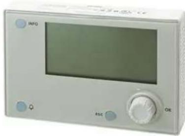
Microtech 4 does not have an integrated HMI. The interaction with the controller can be done using a mobile app that can be download from the store (Playstore for Android devices and Apple Store for iOS devices).

natural_image
Front view of a gray electronic device with multiple ports and connectors (no visible text or symbols)
natural_image
Front view of a computer rack with ventilation slots and two ports (no visible text or labels)Optionally is possible to order the Remote HMI that can be connected to the available CE+ CE- port on the controller. This port is in the bottom connectors row of the controller.
text_image
INFO 45C OK
natural_image
Close-up of a server rack with two labeled buttons and a yellow highlight (no readable text or symbols)3.1 Navigating
When power is applied to the control circuit, the controller screen will be active and display the Home screen, which can also be accessed by pressing the Menu Button.
An example of the HMI screens is shown in the following picture.
| Main Menu 1 / 11 | |
| Enter Password | |
| Unit Status = | |
| Off: Unit SW | |
| Active Set pt = 7.0 °C |
A bell ringing in the top right corner will indicate an active alarm. If the bell doesn't move it means that the alarm has been acknowledged but not cleared because the alarm condition hasn't been removed. A LED will also indicate where the alarm is located between the unit or circuits.

text_image
Main Menu 1 / Enter Password Unit Status = Off: Unit SW Active Set pt = 7.0 °CThe active item is highlighted in contrast, in this example the item highlighted in Main Menu is a link to another page. By pressing the push'n'roll, the HMI will jump to a different page. In this case the HMI will jump to the Enter Password page.
| Enter Password | 2 / 2 | |
| Enter PW | * * * * | |
3.2 Passwords
The HMI structure is based on access levels that means that each password will disclose all the settings and parameters allowed to that password level. Basic information about the status can be accessed without the need to enter the password. The user UC handles two level of passwords:
| USER | 5321 |
| MAINTENANCE | 2526 |
The following information will cover all data and settings accessible with the maintenance password. User password will disclose a subset of the settings explained in chapter.
In the Enter Password screen, the line with the password field will be highlighted to indicate that the field on the right can be changed. This represents a setpoint for the controller. Pressing the push'n'roll the individual field will be highlighted to allow an easy introduction of the numeric password.
| Enter Password | 2 / 2 |
| Enter PW | 5 * * * |
The password will time out after 10 minutes and is cancelled if a new password is entered or the control powers down. Entering an invalid password has the same effect as continuing without a password. It is changeable from 3 to 30 minutes via the Timer Settings menu in the Extended Menus.
3.3 Editing
The Editing Mode is entered by pressing the navigation wheel while the cursor is pointing to a line containing an editable field. Pressing the wheel again cause the new value to be saved and the keypad/display to leave the edit mode and return to the navigation mode.
3.4 Mobile app HMI
The Daikin mAP mobile app HMI is provided for free and aims to simplify the interaction with this Daikin product. The app can be downloaded from the official stores with the following links (scan the QR code to directly access the download pages on the stores).

iOS

Android
To use the app is needed to pre-register an account and gain access to the specific unit to access. The access will be granted per unit base. A user can access multiple units after the app-tenant authorize this access. The procedure to register an account is in app. It's necessary to follow the sign in link in the app:

text_image
User login If you have a Safari AppWizard Europe account you can use it to log us. AUDENTICATE WITH MICROSOFT Add your a new user? SCAN us On log to wait your Safari wAP credentials. Help: PASS/GO Forgot password?
text_image
New user Enter your details to request access. Status Accession My access to the website (e-mail: e-mail: e-mail: e-mail: e-mail: e-mail: e-mail: e-mail: e-mail: e-mail: e-mail: e-mail: e-mail: e-mail: e-mail: e-mail: e-mail: e-mail: e-mail: e-mail: e-mail: e-mail: e-mail: e-mail: e-mail: e-mail: e-mail: e-mail: e-mail: e-mail: e-mail: e-mail: e-mail: e-mail: e-1337 Do you already have an account?The mobile app will allow you to monitor all the relevant data, change the user related settings, trend data, update chiller software and more to come. App layout will adapt based on the device where the app is running and will look as follows:
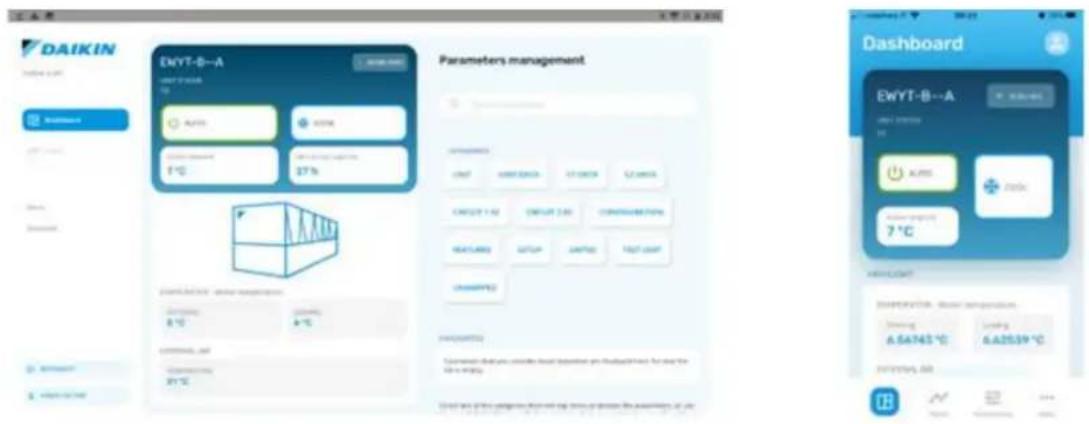

For further information consult the Quick Guide Daikin Map 1.0 - D-EPMAP00101-23_EN.
3.5 Basic Control System Diagnostic
Microtech controller, extension modules and communication modules are equipped with two status LED (BSP and BUS) to indicate the operational status of the devices. The BUS LED indicates the status of the communication with the controller. The meaning of the two status LED is indicated below.
Main Controller (UC)
| BSP LED | Mode |
| Solid Green | Application running |
| Solid Yellow | Application loaded but not running (*) or BSP Upgrade mode active |
| Solid Red | Hardware Error (*) |
| Flashing Green | BSP startup phase. The controller needs time for starting. |
| Flashing Yellow | Application not loaded (*) |
| Flashing Yellow/Red | Fail safe mode (in case that the BSP upgrade was interrupted) |
| Flashing Red | BSP Error (software error*) |
| Flashing Red/Green | Application/BSP update or initialization |
(*) Contact Service.
Extension modules
| BSP LED | Mode | BUS LED | Mode |
| Solid Green | BSP running | Solid Green | Communication running, I/O working |
| Solid Red | Hardware Error (*) | Solid Red | Communication down (*) |
| Flashing Red | BSP Error (*) | Solid Yellow | Communication running but parameter from the application wrong or missing, or incorrect factory calibration |
| Flashing Red/Green | BSP upgrade mode |
Communication modules
BSP LED (same for all modules)
| BSP LED | Mode |
| Solid Green | BPS running, communication with controller |
| Solid Yellow | BSP running, no communication with controller (*) |
| Solid Red | Hardware Error (*) |
| Flashing Red | BSP Error (*) |
| Flashing Red/Green | Application/BSP update |
(*) Contact Service.
BUS LED
| BUS LED | LON | Bacnet MSTP | Bacnet IP | Modbus |
| Solid Green | Ready for Communication. (All Parameter loaded; Neuron configured). Doesn't indicate a communication with other devices. | Ready for Communication. The BACnet Server is started. It doesn't indicate an active communication. | Ready for Communication. The BACnet Server is started. It doesn't indicate an active communication. | All Communication running |
| Solid Yellow | Startup | Startup | Startup. The LED stays yellow until the module receives a IP Address, therefore a link must be established. | Startup, or one configured channel not communicating to the Master |
| Solid Red | No Communication to Neuron (internal error, could be solved by downloading a new LON application). | BACnet Server down. Automatically a restart after 3 seconds is initiated. | BACnet Server down. Automatic restart after 3 seconds is initiated. | All configured Communications down. Means no communication to the Master. The timeout can be configured. In case that the timeout is zero the timeout is disabled. |
| Flashing Yellow | Communication not possible to the Neuron. The Neuron must be configured and set online over the LON Tool. |
3.6 Controller maintenance
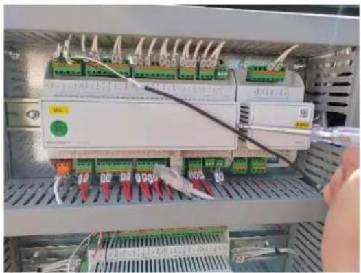
The controller requires to maintain the installed battery. Every two years it's required to replace the battery. Battery model is: BR2032 and it is produced by many different vendors. To replace the battery, remove the plastic cover of the controller display using a screw driver as shown in the following pictures:
natural_image
Interior view of an electronic control panel with multiple connected modules and wiring (no visible text or symbols)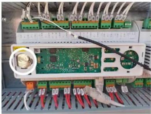
natural_image
Interior view of an electronic control panel with a green circuit board and wiring, no visible text or symbolsBe careful to avoid damages to the plastic cover. The new battery shall be placed in the proper battery holder, which is highlighted in the picture, respecting the polarities indicated into the holder itself.
3.7 Optional Remote User Interface
As an option an external Remote HMI can be connected on the UC. The Remote HMI offers the same features as the inbuilt display plus the alarm indication done with a light emitting diode located below the bell button.
All viewing and setpoint adjustments available on the unit controller are available on the remote panel. Navigation is identical to the unit controller as described in this manual.

text_image
MicroTech®The Remote HMI can be extended up to 700m using the process bus connection available on the UC. With a daisy-chain connection as below, a single HMI can be connected to up to 8 units. Refer to the specific HMI manual for details.
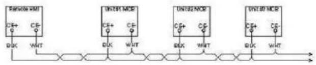
flowchart
graph LR
    A["RSROM"] --> B["UDT1MOS"]
    B --> C["UDT2MOS"]
    C --> D["UDT30MOS"]
    subgraph Inputs
        E["CE+"] --> F["BUK"]
        G["CE-"] --> H["WHT"]
    end
    subgraph Outputs
        I["BUK"] --> J["WHT"]
    end
3.8 Embedded Web Interface
The Microtech controller has an embedded web interface that can be used to monitor the unit when connected to a local network. It is possible to configure the IP addressing of the Microtech as a fixed IP of DHCP depending on the network configuration.
With a common web browser, a PC can connect with the unit controller entering the IP address of the controller or the host name, both visible in the "About Chiller" page accessible without entering a password.
When connected, it will be required to enter a username and a password. Enter the following credential to get access to the web interface:
Username: Daikin
Password: Daikin@web
Sign in to access this site
Authorization required by http://192.168.1.42
Your connection to this site is not secure

text_image
Username PasswordSign in
Cancel
The Main Menu page will be displayed. The page is a copy of the onboard HMI and follows the same rules in terms of access levels and structure.
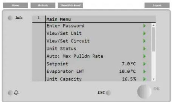
text_image
Info 1 Main Menu Enter Password View/Set Unit View/Set Circuit Unit Status Auto: Max Pulldn Rate Setpoint 7.0°C Evaporator LWT 10.0°C Unit Capacity 16.5%
line
| Date | Setpoint | Evaporater EWT | | ---------- | -------- | -------------- | | 08-59-45 | 12 | 7 | | 08-59-30 | 12 | 7 | | 08-59-15 | 12 | 7 | | 08-59-20 | 12 | 7 | | 08-59-21 | 12 | 7 | | 08-59-30 | 12 | 7 | | 08-59-35 | 12 | 7 |In addition, it allows to trend log a maximum of 5 different quantities. It's required to click on the value of the quantity to monitor and the following additional screen will become visible:
Depending on the web browser and its version the trend log feature may not be visible. It's required a web browser supporting HTML 5 like for example:
• Microsoft Internet Explorer v.11,
• Google Chrome v.37,
- Mozilla Firefox v.32.
These software are only an example of the browser supported and the versions indicated have to be intended as minimum versions.
4.1 Chiller On/Off
Starting from factory setup, unit On/Off can be managed by the user using the selector Q0, placed in the electrical panel, which can switch between three positions: 0 - Local - Remote.

0
Unit is disabled
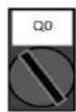
Loc (Local)
Unit is enabled to start the compressors
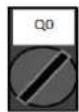
Rem (Remote)
Unit On/Off is managed through the "Remote On/Off" physical contact.
Closed contact means unit enabled.
Opened contact means unit disabled.
Refer to the electrical wiring diagram, Field Wiring Connection page, to find the references about Remote On/Off contact. Generally, this contact is used to bring out from the electrical panel the on/off selector
Unit controller provides also additional software features to manage unit start/stop, that are set by default to allow unit start:
- Keypad on/off
- Scheduler (Time programmed On/Off)
- Network On/Off (optional with communication modules)
4.1.1 Keypad On/Off
In the main page, scroll down until Unit Enable menu, where are available all settings to manage unit and circuits start/stop.
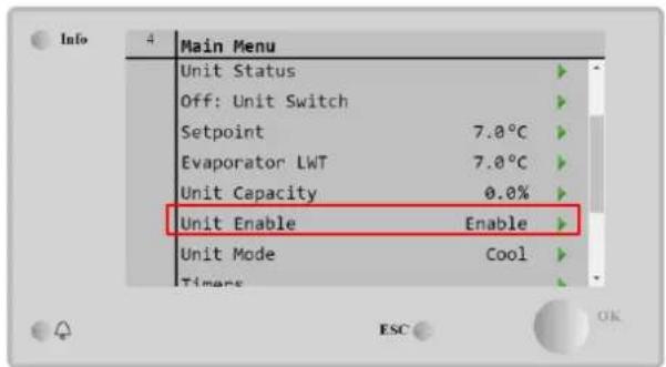
text_image
Info 4 Main Menu Unit Status Off: Unit Switch Setpoint 7.0°C Evaporator LWT 7.0°C Unit Capacity 0.0% Unit Enable Enable Unit Mode Cool Timers ESC OK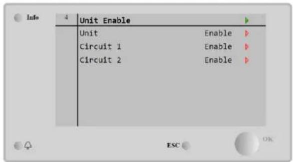
text_image
Info 4 Unit Enable Unit Enable Circuit 1 Enable Circuit 2 Enable| Parameter | Range | Description |
| Unit | Disable | Unit disabled |
| Enable | Unit enabled | |
| Scheduler | Unit start/stop can be time programmed for each weekday | |
| Circuit #X | Disable | Circuit #X disabled |
| Enable | Circuit #X enabled | |
| Test | Circuit #X in test mode. This feature has to be used only from trained person or Daikin service |

text_image
Unit Enable Disable Enable Scheduler Save Cancel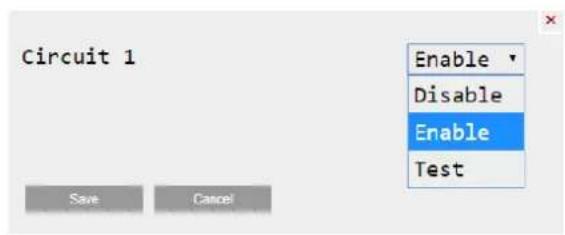
text_image
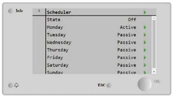
Circuit 1 Enable Disable Enable Test Save Cancel4.1.2 Scheduler and Silent mode functionalities
The Scheduler function can be used when is required an automatic chiller start/stop programming.
To use this function, follow below instructions:
- Q0 selector = Local
- Unit Enable = Scheduler
- Controller date and time properly set
Scheduler programming is available going in Main Page → View/Set Unit → Scheduler menu
text_image
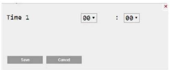
Info 4 Scheduler State Off Monday Active Tuesday Passive Wednesday Passive Thursday Passive Friday Passive Saturday Passive Sunday Passive ESC OK
text_image
Info 01:Monday Time 1 00:00 Value 1 Off Time 2 07:30 Value 2 Off Time 3 *:** Value 3 Off Time 4 *:** Value 4 Off ESC OKFor each weekday can be programmed up to six-time bands with a specific operating mode. First operating mode starts at Time 1, ends at Time 2 when will start the second operating mode and so on until the latest.
text_image
Time 1 00 • : 00 • Save Cancel
text_image
Value 1 Off Off On 1 On 2 On 1 - Silent On 2 - SilentDepending on unit type, different operating modes are available:
| Parameter | Range | Description |
| Value 1 | off | Unit disabled |
| On Setpoint 1 | Unit enabled – Water setpoint 1 selected | |
| On Setpoint 2 | Unit enabled – Water setpoint 2 selected | |
| On 1 - Silent | Unit enabled – Water setpoint 1 selected – Fan silent mode enabled | |
| On 2 - Silent | Unit enabled – Water setpoint 2 selected – Fan silent mode enabled |
When the Fan Silent Mode function is enabled the chiller noise level is reduced decreasing the maximum speed allowed for fans. Maximum Speed of Fans is reduced to 75% to reduce noise level.
4.1.3 Network On/Off
Chiller On/off can be managed also with serial protocol, if the unit controller is equipped with one or more communication modules (BACNet, Modbus or LON). To control the unit over the network, follow below instructions:
- Q0 selector = Local
- Unit Enable = Enable
- Control Source = Network
- Close the contact Local/Network Switch, when required!
4.2 Water Setpoints
Purpose of this unit is to cool or to heat (in case of heat pump) the water temperature, to the setpoint value defined by the user and displayed in the main page:

text_image
Main Menu Enter Password View/Set Unit View/Set Circuit Unit Status Off: Unit Switch Setpoint 7.0°C Evaporator LWT 7.0°C Unit Capacity 0.0%
text_image
Info 2 Tmp Setpoints Cool LWT 1 7.0°C Cool LWT 2 7.0°C Ice LWT -4.0°C Max LWT 18.0°C Min LWT -8.0°C HR EWT Sp 40.0°C HR EWT Dif 2.0°C HR Lock Limit 25.0°C ESC OKThe unit can work with a primary or a secondary setpoint, that can be managed as indicated below:
- Keypad selection + Double Setpoint digital contact
- Keypad selection + Scheduler Configuration
- Network
- Setpoint Reset function
As first step the primary and secondary setpoints need to be defined. From main menu, with user password, press on Setpoint.
| Parameter | Range | Description |
| Cool LWT 1 | Ranges of the Cool, Heat, Ice setpoint are reported in the IOM of every specific unit. | Primary cooling setpoint. |
| Cool LWT 2 | Secondary cooling setpoint. | |
| Ice LWT | Setpoint for Ice mode. | |
| Max LWT | High limit for Cool LWT1 and Cool LWT2 | |
| Min LWT | Low limit for Cool LWT1 and Cool LWT2 | |
| HR EWT Sp | Heat Recovery Entering Water Setpoint | |
| HR Dif | Heat Recovery Water Temperature differential | |
| HR Lock Limit | Heat Recovery Lock Limit | |
| HR Delta Sp | Heat Recovery Delta Setpoint |
The change between primary and secondary setpoint can be performed using the Double setpoint contact, always available in the user terminal box, or through the Scheduler function.
Double setpoint contact works as below:
- Contact opened, the primary setpoint is selected
- Contact closed, the secondary setpoint is selected

When the scheduler function is enabled, the Double setpoint contact is ignored

When the operating mode Cool/Ice w/Glycol is selected, the Double Setpoint contact will be used to switch between the Cool and Ice mode, producing no change on the active setpoint
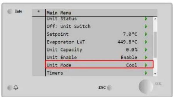
4.3 Unit Mode
The Unit Mode is used to define if the chiller is working to produce chilled or heated water. Current mode is reported in the main page to the item Unit Mode.
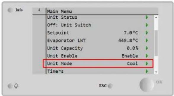
text_image
Info 4 Main Menu Unit Status Off: Unit Switch Setpoint 7.0°C Evaporator LWT 449.8°C Unit Capacity 0.0% Unit Enable Enable Unit Mode Cool Timers ESC OK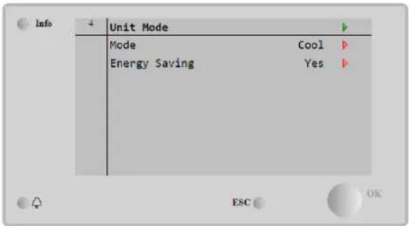
text_image
Info 4 Unit Mode Mode Cool Energy Saving Yes ESC OKDepending on the unit type, different operating modes can be selected entering, with maintenance password, in the Unit Mode menu. In the table below are listed and explained all modes.
| Parameter | Range | Description | Unit Range |
| Mode | Cool | Set if chilled water temperature up to 4°C is required. No glycol is generally needed in the water circuit, unless ambient temperature may reach low values. | A/C |
| Cool w/Glycol | Set if chilled water temperature below 4°C is required. This operation requires proper glycol/water mixture in the evaporator water circuit. | A/C | |
| Cool/Ice w/Glycol | Set in case a dual cool/ice mode is required. The switch between the two modes is performed using the contact physical Double Setpoint.Double Setpoint opened: the chiller will work in cooling mode with the Cool LWT being as the Active Setpoint.Double Setpoint closed: The chiller will work in Ice mode with the Ice LWT as the Active Setpoint. | A/C | |
| Ice w/Glycol | Set if Ice storage is required. The application requires the compressors to operate at full load until the ice bank is completed, and then to stop for at least 12 hours. In this mode the compressor(s) will not operate at part load but will work only in on/off mode. | A/C | |
| Test | Enables the Manual Control of the unit. The manual test feature helps in debugging and checking the operational status of actuators. This feature is accessible only with the maintenance password in the main menu. To activate the test feature is required to disable the Unit from the Q0 switch and change the available mode to Test. | A/C | |
| Energy Saving | No, Yes | Disable/Enable of the energy saving function |
Like the On/Off and setpoint control, also the unit mode can be modified from network.
4.3.1 Energy Saving mode
Some unit types provide the possibility to enable an energy saving function, that reduces the power consumption deactivating the compressors crankcase heater, when the chiller is Disabled.
This mode implies that the time needed to start the compressors, after an Off period, could be delayed until a maximum of 90 minutes.
For time critical application, the energy saving function can be disabled by the user to ensure the compressor start within 1 minute from unit On command.
text_image
Info 4 Main Menu Unit Status Off: Unit Switch Setpoint 7.0°C Evaporator LWT 449.8°C Unit Capacity 0.0% Unit Enable Enable Unit Mode Cool Timers ESC OK
text_image
Info 4 Unit Mode Mode Cool Energy Saving Yes ESC OK4.4 Unit Status
Unit controller provides in the main page some information about chiller status. All chiller states are listed and explained below:
| Parameter | Overall status | Specific status | Description |
| Unit Status | Auto: | Unit is in Auto control. The pump is running and at least one compressor is running. | |
| Wait For Load | Unit is in standby because the thermostatic control satisfies the active setpoint. | ||
| Water Recirc | Water pump is running in order to equalize the water temperature in the evaporator. | ||
| Wait For Flow | Unit pump is running but the flow signal still indicates a lack of flow through the evaporator. | ||
| Max Pulldown | Unit thermostatic control is limiting the unit capacity as the water temperature is dropping too quickly. | ||
| Capacity Limit | Demand limit has been hit. Unit capacity will not further increase. | ||
| Current Limit | Maximum current has been hit. Unit capacity will not further increase. | ||
| Silent Mode | Unit is running and Silent Mode is enabled | ||
| Pumpdown | Unit is performing the pumpdown procedure and d it will stop within few minutes | ||
| Off: | Master Disable | Unit is disabled by the Master Slave function | |
| Ice Mode Timer | This status can be shown only if the unit can work in Ice Mode. The unit is off because the Ice setpoint has been satisfied. Unit will remain off until the Ice Timer has expired. | ||
| OAT Lockout | The unit cannot run because the Oustide Air Temperature is below the limit foreseen for the condenser temperature control system installed in this Unit. If the Unit has to run anyway, check with your local maintenance how to proceed. | ||
| Circuits Disabled | No circuit is available to run. All circuits can be disabled by their individual enable switch or can be disabled by a component safety condition active or can be disabled by keypad or can be all in alarms. Check the individual circuit status for further details. | ||
| Unit Alarm | A unit alarm is active. Check the alarm list to see what the active alarm is inhibiting the unit to start and check if the alarm can be cleared. Refer to section 5. before proceeding. | ||
| Keypad Disable | The Unit has been disabled by keypad. Check with your local maintenance if it can be enabled. | ||
| Network Disabled | Unit is disabled by Network. | ||
| Unit Switch | The Q0 selector is set to 0 or the or the Remote On/Off contact is opened. | ||
| Test | Unit mode set to Test. This mode is activated to check operability of onboard actuators and sensors. Check with the local maintenance if the Mode can be reverted to the one compatible with unit application (View/Set Unit - Set-Up - Available Modes). | ||
| Scheduler Disable | Unit is disabled by Scheduler programming |
4.5 Network Control
When the unit controller is equipped with one or more communication modules the Network Control feature can be enabled, which gives the possibility to control the unit via serial protocol (Modbus, BACNet or LON). To allow unit's control from network, follow below instructions:
-
Close the physical contact "Local/Network Switch". Refer to unit electrical wiring diagram, Field wiring Connection page, to find the references about this contact.
-
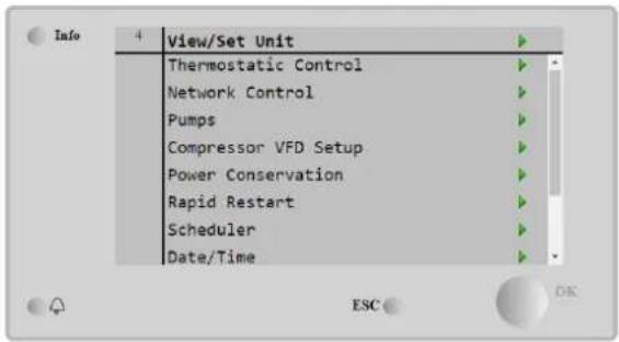
Go to Main Page → View/Set Unit → Network Control Set Controls Source = Network
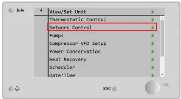
text_image
Info 4 View/Set Unit Thermostatic Control Network Control Pumps Compressor VFD Setup Power Conservation Heat Recovery Scheduler Date/Time
text_image
Info 4 Network Ctrl Control Source Network Actual Control Network Enable Disable Mode Cool Cool LWT 7.0°C Heat LWT 45.0°C Ice LWT -4.0°C Current Limit 2001 ESC OKNetwork Control menu returns all main values received from serial protocol.
| Parameter | Range | Description |
| Control Source | Local | Network control disabled |
| Network | Network control enabled | |
| Actual Control | Local, Network | Active control between Local/BMS. |
| Enable | - | On/Off command from network |
| Mode | - | Operating mode from network |
| Cool LWT | - | Cooling water temperature setpoint from network |
| Heat LWT | - | Heating water temperature setpoint from network |
| Ice LWT | - | Ice water temperature setpoint from network |
| Current Limit | Setpoint for current limitation from BMS | |
| Capacity Limit | - | Capacity limitation from network |
| Remote Server | Remote servers enable |
Refer to communication protocol documentation for specific registers addresses and the related read/write access level.
4.6 Thermostatic Control
Thermostatic control settings, allows to set up the response to temperature variations. Default settings are valid for most application, however plant specific conditions may require adjustments in order to have a smooth control or a quicker response of the unit.
The control will start the first compressor if the controlled temperature is higher (Cool Mode) or lower (Heat Mode) than the active setpoint of at least a Start Up DT value, whereas other compressors are started, step by step, if the controlled temperature is higher (Cool Mode) or lower (Heat Mode) than the active setpoint (AS) of at least a Stage Up DT (SU) value. Compressors stop if performed following same procedure looking to the parameters Stage Down DT and Shut Down DT.
| Cool Mode | Heat Mode | |
| First compressor starts | Controlled Temperature > Setpoint + Start Up DT | Controlled Temperature < Setpoint - Start Up DT |
| Other compressors start | Controlled Temperature > Setpoint + Stage Up DT | Controlled Temperature < Setpoint - Stage Up DT |
| Last compressor stop | Controlled Temperature < Setpoint - Shut Dn DT | Controlled Temperature > Setpoint - Shut Dn DT |
| Other compressors stop | Controlled Temperature < Setpoint - Stage Dn DT | Controlled Temperature > Setpoint - Stage Dn DT |
A qualitative example of compressors start-up sequence in cool mode operation is shown in the graph below.
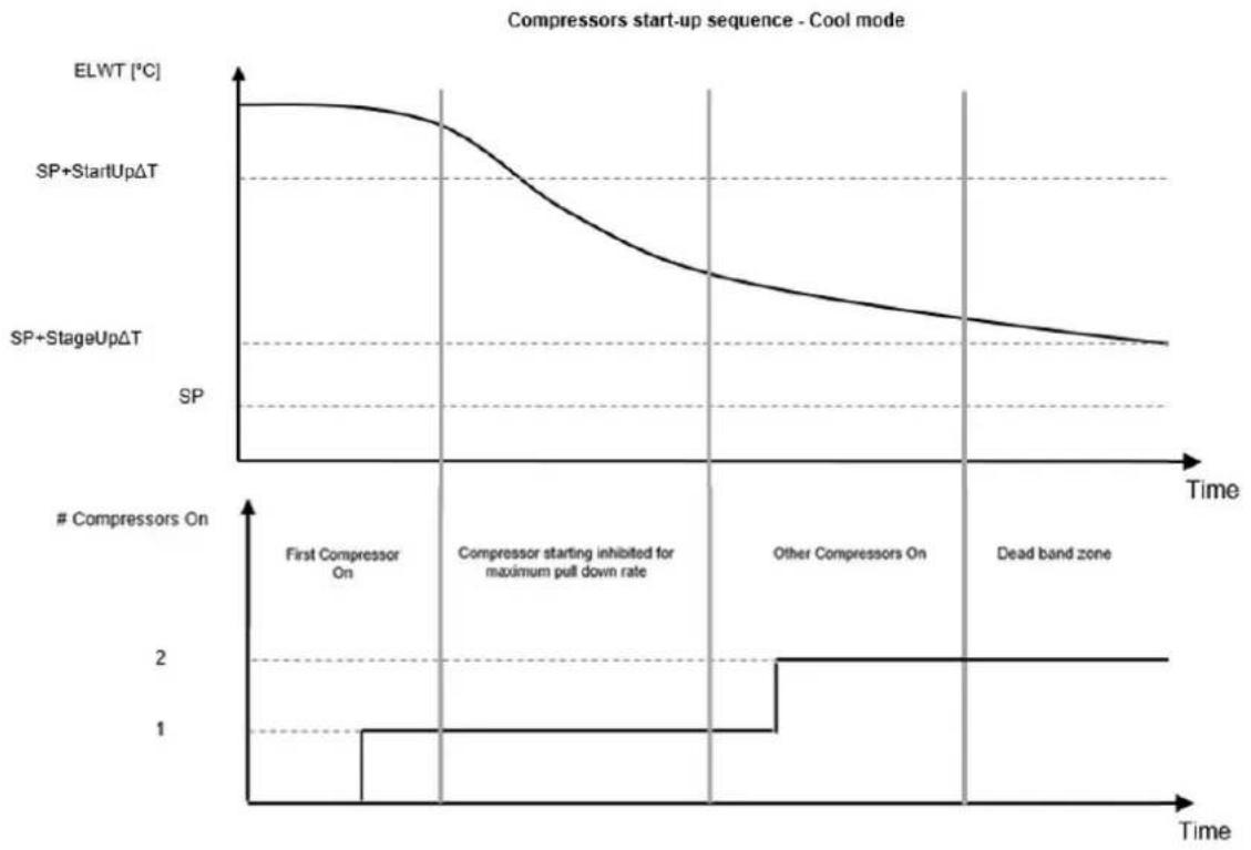
line
| Time Segment | ElWT [°C] | SP+StartUpΔT | SP+StageUpΔT | | ------------------------- | --------- | ------------ | ------------ | | First Compressor On | ~1.0 | - | - | | Compressor starting inhibited for maximum pull down rate | - | - | - | | Other Compressors On | - | - | - | | Dead band zone | - | - | - |When controlled temperature is within the dead band (DB) error from the active setpoint (AS), unit capacity will not be changed.
If the leaving water temperature decreases below (Cool Mode) or rises above (Heat Mode) the active setpoint (AS), unit capacity is adjusted to keep it stable. A further decreasing (Cool Mode) or increasing (Heat Mode) of the controlled temperature of the Shut Down DT offset (SD) can cause circuit shutdown.
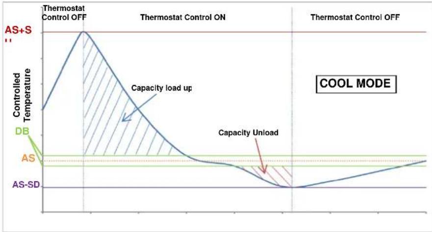
line
| Phase | Controlled Temperature | | ------------------ | ---------------------- | | AS+S | High | | Capacity load up | Medium | | Capacity Unload | Low | | COOL MODE | Low |Thermostatic control settings are accessible from Main Page→Thermostatic Control

text_image
View/Set Unit Thermostatic Control Network Control Pumps Compressor VFD Setup Power Conservation Heat Recovery Scheduler Date/Time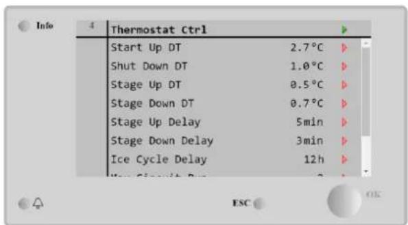
text_image
Info 4 | Thermostat Ctrl | Start Up DT 2.7°C Shut Down DT 1.0°C Stage Up DT 0.5°C Stage Down DT 0.7°C Stage Up Delay 5min Stage Down Delay 3min Ice Cycle Delay 12h| Parameter | Range | Description |
| Start Up DT | 0-5°C | Delta temperature respect the active setpoint to start the unit (startup of first compressor) |
| Shut Down DT | 0-3°C | Delta temperature respect the active setpoint to stop the unit (shutdown of latest compressor) |
| Stage Up DT | 0-1.7°C | Delta temperature respect the active setpoint to start a compressor |
| Stage Down DT | 0-3°C | Delta temperature respect the active setpoint to stop a compressor |
| Stage Up Delay | 0-60 min | Minimum time between the compressors startup |
| Stage Down Delay | 3-30 min | Minimum time between the compressors shutdown |
| Ice Cycle Delay | 1-23 h | Unit standby period during Ice mode operation |
| Max Circuits Run | 1-2 | Limit to the number of circuits to be used |
| Next Circuit On | Shows next circuit to be started up | |
| Next Circuit Off | Shows next circuit number to be stopped |
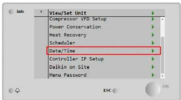
4.7 Date/Time
The unit controller can take stored the actual date and time, that are used for:
- Scheduler
- Cycling of standby chiller with Master Slave configuration
- Alarms Log
Date and time can be modified going in View/Set Unit → Date/Time
text_image
Info 4 View/Set Unit Compressor VFD Setup Power Conservation Heat Recovery Scheduler Date/Time Controller IP Setup Daikin on Site Menu Password ESC OK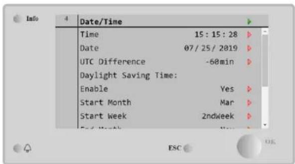
text_image
Date/Time Time 15:15:28 Date 07/25/2019 UTC Difference -60min Daylight Saving Time: Enable Yes Start Month Mar Start Week 2ndweek End Month ESC OK| Parameter | Range | Description |
| Time | Actual date. Press to modify. Format is hh:mm:ss | |
| Date | Actual time. Press to modify. Format is mm/dd/yy | |
| Day | Returns the day of the week. | |
| UTC Difference | Coordinated universal time. | |
| Daylight Saving Time: | ||
| Enable | No, Yes | It is used to enable/disable the automatic switch of the Daylight Saving Time |
| Start Month | NA, Jan...Dec | Daylight Saving time start month |
| Start Week | 1^st...5^th week | Daylight Saving time start week |
| End Month | NA, Jan...Dec | Daylight Saving time end month |
| End Week | 1^st...5^th week | Daylight Saving time end week |

Remember to check periodically the controller battery in order to maintain updated date and time even when there is no electrical power. Refer to controller maintenance section.
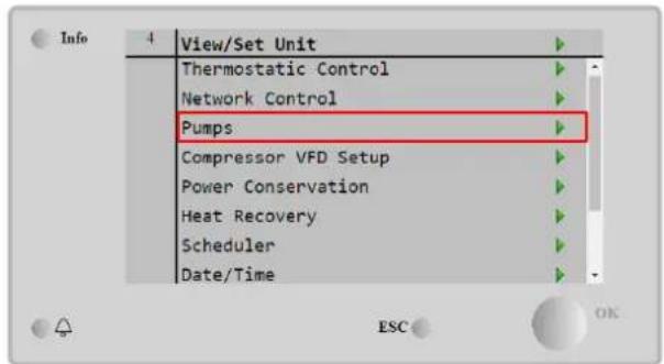
4.8 Pumps
The UC can manage one or two water pumps for both evaporators. Number of pumps and their priority can be set from Main Page→View/Set Unit→Pumps.
text_image
Info 4 View/Set Unit Thermostatic Control Network Control Pumps Compressor VFD Setup Power Conservation Heat Recovery Scheduler Date/Time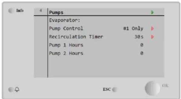
text_image
Info 4 Pumps Evaporator: Pump Control #1 Only Recirculation Timer 30s Pump 1 Hours 0 Pump 2 Hours 0 ESC OK| Parameter | Range | Description |
| Pump Control | #1 Only | Set to this in case of single pump or twin pump with only #1 operational (f.e. in case of maintenance on #2) |
| #2 Only | Set to this in case of twin pump with only #2 operational (f.e. in case of maintenance on #1) | |
| Auto | Set for automatic pump start management. At each chiller start, the pump with the least number of hours will be | |
| #1 Primary | Set to this in case of twin pump with #1 running and #2 as a backup | |
| #2 Primary | Set to this in case of twin pump with #2 running and #1 as a backup | |
| Recirculation Timer | Minimum time required within flow switch has to in order to allow unit startup | |
| Pump 1 Hours | Pump 1 running hours | |
| Pump 2 Hours | Pump 2 running hours |
4.9 External Alarm
The External Alarm is a digital contact that can be used to communicate to the UC an abnormal condition, coming from an external device connected to the unit. This contact is in the customer terminal box and depending on the configuration can causes a simple event in the alarm log or also the unit stop. The alarm logic associated to the contact is the following:
| Contact state | Alarm State | Note |
| Opened | Alarm | The alarm is generated if the contact remains opened for at least 5 seconds |
| Closed | No Alarm | The alarm is reset just the contact is closed |
The configuration is performed from the Commissioning → Configuration → Options menu
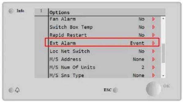
text_image
Options Fan Alarm No Switch Box Temp No Rapid Restart No Ext Alarm Event Loc Net Switch No M/S Address None M/S Num Of Units 2 M/S Sns Type None ESC OK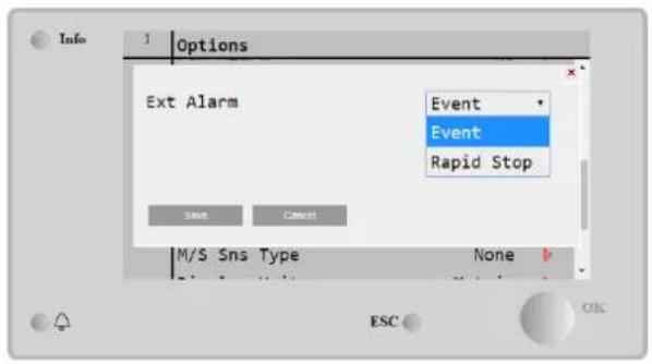
text_image
Info 1 Options Ext Alarm Event Event Rapid Stop Save Cancel M/S Sns Type None ESC OK| Parameter | Range | Description |
| Ext Alarm | Event | Event configuration generates an alarm in the controller but takes the unit running |
| Rapid Stop | Rapid Stop configuration generates an alarm in the controller and performs a rapid stop of the unit |

At the end of the Setpoint Reset configuration, execute an Apply Changes to make the configurations made effective.
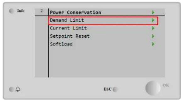
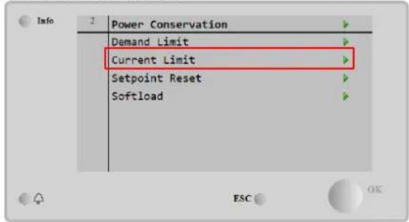
4.10 Power Conservation
In this chapters will be explained the functions used to reduce the unit power consumption:
- Demand Limit
- Current Limit
- Setpoint Reset
- Softload

text_image
Info 4 Power Conservation Demand Limit Current Limit Setpoint Reset SoftloadMain Menu→View / Set Unit→Power Conservation
4.10.1 Demand Limit
The "Demand limit" function allows the unit to be limited to a specified maximum load. Capacity limit level is regulated using an external 4-20 mA signal with a linear relationship shown in the picture below. A signal of 4 mA indicates the maximum capacity available whereas a signal of 20 mA indicates the minimum capacity available. With demand limit function is not possible shutdown the unit but only unload it until minimum admissible capacity. Demand limit related setpoints available through this menu are listed in the table below.
To enable this option, go to Main Menu → Commission Unit → Configuration → Options and set the Demand Limit parameter to Enable.

At the end of the Setpoint Reset configuration, execute an Apply Changes to make the configurations made effective.
All info about this function is reported in the Main Menu → View/set Unit → Power Configuration → Demand Limit page.
text_image
Info 2 Power Conservation Demand Limit Current Limit Setpoint Reset Softload ESC OK
text_image
Info 2 Demand Limit Unit Capacity 0.0% Demand Limit 75.0% ESC OK
line
| Demand Limit [mA] | Capacity Limit [%] | |---|---| | 4 | Maximum Capacity | | 20 | Minimum Capacity || Parameter | Description |
| Unit Capacity | Displays current unit capacity |
| Demand Limit En | Enables demand limit |
| Demand Limit | Displays active demand limit |
4.10.2 Current Limit
Current limit function allows to control unit power consumption taking current drawn below a specific limit. If external digital signal is triggered, the function Current Limit is activated, and the user can set a Current Limit Setpoint defined through the HMI or BAS communication.
If Flexible Current Limit Option is activated, by Commissioning → Configuration → Options → Flex Current Limit, user can decrease the real limit using an external 4-20mA signal as indicate in the graph below. With 20 mA real current limit is set to Current Limit Setpoint, whereas with 4 mA signal the unit is unloaded until minimum capacity.
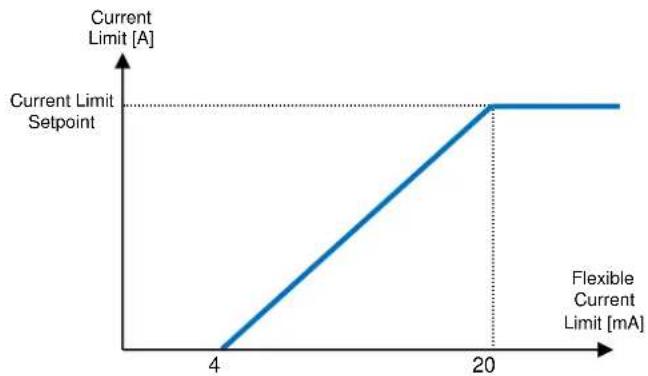
line
| Flexible Current Limit [mA] | Current Limit [A] | | --------------------------- | ----------------- | | 4 | 0 | | 20 | 20 || Parameter | Description |
| Unit Current | Actual Chiller Current |
| Current Limit | Active Current Limit |
| Current Setpoint | Current Setpoint. Overwrite by external 4-20 mA signal if Flex Curr Limit is activated. |
All info about this function are reported in the Main Menu → view/set Unit → Power Configuration → Current Limit page.
text_image
Info Power Conservation Demand Limit Current Limit Setpoint Reset Softload ESC
text_image
Info 2 Current Limit Unit Current 0.0A Current Limit 700A Current Setpoint 700A ESC OK4.10.3 Setpoint Reset
The setpoint reset function overrides the chilled water temperature selected through the interface, when certain circumstances occur. This feature helps in reducing energy consumption optimizing comfort as well. Three different control strategies can be selected:
- Setpoint Reset by Outside Air Temperature (OAT)
- Setpoint Reset by an external signal (4-20mA)
- Setpoint Reset by Evaporator T (Return)
To set the desired setpoint-reset strategy, go to Main Menu → Commission Unit → Configuration → Options and modify the Setpoint Reset parameter, according to the following table:
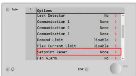
text_image
Info 1 Options Leak Detector No Communication 1 None Communication 2 None Communication 3 None Demand Limit Disable Flex Current Limit Disable Setpoint Reset None Fan Alarm No
text_image
Info Power Conservation Setpoint Reset None None 4-20mA Return 0at Save Cancel Softload Softload Ramp 310bit 20min ESC OK| Parameter | Description |
| Max Reset | Max Setpoint Reset (valid for all active modes) |
| Start Reset DT | Used on Setpoint Reset by Evaporator DT |
| Max Reset OAT | See Setpoint Reset by OAT Reset |
| Strt Reset OAT | See Setpoint Reset by OAT Reset |
Each strategy needs to be configured (although a default configuration is available) and its parameters can be set navigating to Main Menu → View/Set Unit → Power Conservation → Setpoint Reset.

At the end of the Setpoint Reset configuration, execute an Apply Changes to make the configurations made effective.
4.10.3.1 Setpoint Reset by OAT
The active setpoint is calculated applying a correction which is a function of ambient temperature (OAT). As temperature drops below the Start Reset OAT (SROAT), LWT setpoint is gradually increased until OAT reaches the Max Reset OAT value (MROAT). Beyond this value, the LWT setpoint is increased by the Max Reset (MR) value.

line
| OAT | A | | ------- | ----- | | MROAT | LWT SP + MR | | SROAT | LWT SP || Parameter | Range |
| Max Reset (MR) | 0.0^ ÷ 10.0^ |
| Start Reset DT | 10.0^ ÷ 29.4^ |
| Max Reset OAT (MROAT) | 10.0^ ÷ 29.4^ |
| Start Reset OAT (SROAT) | 10.0^ ÷ 29.4^ |
4.10.3.2 Setpoint Reset by External 4-20 mA signal
The active setpoint is calculated applying a correction based on an external 4-20mA signal. 4 mA corresponds to 0°C correction, while 20 mA corresponds to a correction of the active setpoint as set in Max Reset (MR).
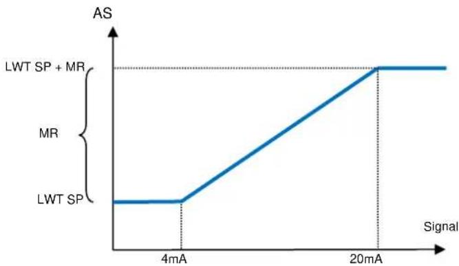
line
| Signal | AS | |--------|--------| | 4mA | LWT SP | | 20mA | 1 || Parameter | Range |
| Max Reset (MR) | 0.0^ ÷ 10.0^ |
| Start Reset DT | 10.0^ ÷ 29.4^ |
| Max Reset OAT (MROAT) | 10.0^ ÷ 29.4^ |
| Start Reset OAT (SROAT) | 10.0^ ÷ 29.4^ |
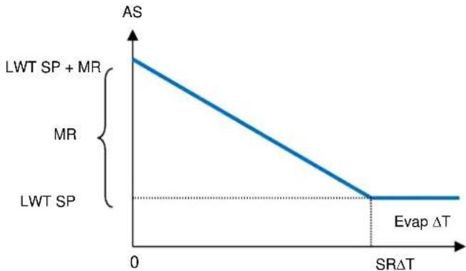
4.10.3.3 Setpoint Reset by Return
The active setpoint is calculated applying a correction that depends on the evaporator entering (return) water temperature. As evaporator T becomes lower than the SR T value, an offset to the LWT setpoint is increasingly applied, up to the MR value when the return temperature reaches the chilled water temperature.

The Return Reset may affect negatively the chiller operation when operated with variable flow. Avoid to use this strategy in case of inverter water flow control.
line
| SRΔT | AS | |------|----| | 0 | AS | | >SRΔT | 0 || Parameter | Range |
| Max Reset (MR) | 0.0^ ÷ 10.0^ |
| Start Reset DT | 10.0^ ÷ 29.4^ |
| Max Reset OAT (MROAT) | 10.0^ ÷ 29.4^ |
| Start Reset OAT (SROAT) | 10.0^ ÷ 29.4^ |
4.10.4 Softload
Soft Loading is a configurable function used to ramp up the unit capacity over a given time period, usually used to influence building electrical demand by gradually loading the unit. To enable Softload, go to the page:
Main Menu→View / Set Unit→Power Conservation→ Softload

text_image
Info Power Conservation Demand Limit Current Limit Setpoint Reset Softload
text_image
Info Softload Softload Enable Disable Softload Ramp 20min Starting Cap 40.0% ESC OKOnce the Softload Ramp and the Starting Cap have been set, if the Softload is enabled, the machine is forced to ramp up the capacity based on settings. It works when the machine is starting from 0%, reaching the maximum load with the speed settable by the customer.
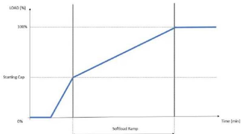
line
| Time [min] | LOAD [%] | | ---------- | -------- | | 0 | 0 | | Low | 0 | | Mid | 50 | | High | 100 || Parameter | Description |
| Softload Enable | Enables soft loading |
| Softload Ramp | Duration of the soft load ramp |
| Starting Cap | Begin capacity limit. Unit will increase capacity from this value to 100% over the time specified by the Softload Ramp setpoint. |
If the Softload is enabled when the machine is already running, if the Starting Cap>Actual Capacity, the Softload will ramp up the Capacity with the speed set by the customer.
4.11 Electrical Data
Unit controller returns main electrical values read by the energy meter Nemo D4-L, Nemo D4-Le or NanoH. All data are collected in the menu Electrical Data.
Main Page → View/Set Unit → Electrical Data

text_image
View/Set Unit Compressor VFD Setup Power Conservation Heat Recovery Electrical Data Scheduler Date/Time Controller IP Setup Daikin on Site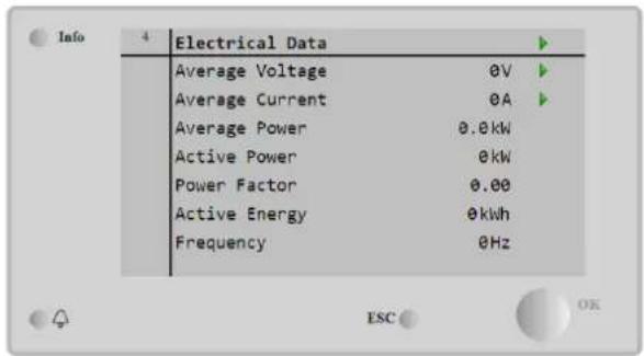
text_image
Info 4 Electrical Data Average Voltage 0V Average Current 0A Average Power 0.0kW Active Power 0kW Power Factor 0.00 Active Energy 0kWh Frequency 0Hz| Parameter | Description |
| Average Voltage | Returns the average of the three chained voltages and links to the Voltage Data page |
| Average Current | Returns the current average and links to the Current Data page |
| Average Power | Returns the average power |
| Active Power | Returns the active power |
| Power Factor | Returns the power factor |
| Active Energy | Returns the active energy |
| Frequency | Returns the active frequency |
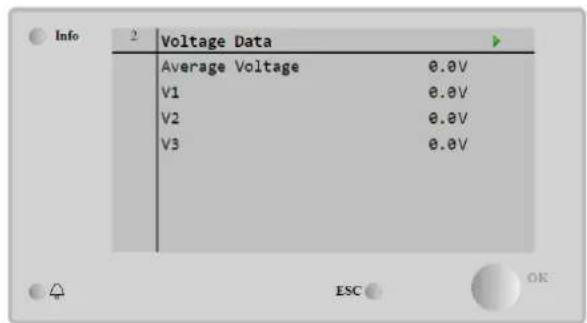
text_image
Info Voltage Data Average Voltage 0.0V V1 0.0V V2 0.0V V3 0.0V ESC OK
text_image
Info 2 Current Data Average Current 0.0A I1 0.0A I2 0.0A I3 0.0A ESC OK4.12 Controller IP Setup
The Controller IP Setup page is located at the path Main Menu → view/Set Unit → Controller IP Setup.

text_image
Info View/Set Unit Compressor VFD Setup Power Conservation Heat Recovery Electrical Data Scheduler Date/Time Controller IP Setup Daikin on Site
text_image
Info 2 IP Setup Settings DHCP Off IP 192.168.001.042 Mask 255.255.255.000 Gateway 192.168.001.001 PrimDNS 10.39.148.17 SecDNS 0.0.0.0 Name POL69U EB4BB4All the information about current MT4 IP Network settings is reported in this page, as shown in the following table:
| Parameter | Range | Description |
| DHCP | On | The DHCP option is enabled. |
| off | The DHCP option is disabled. | |
| IP | xxx.xxx.xxx.xxx | The current IP address |
| Mask | xxx.xxx.xxx.xxx | The current Subnet Mask address. |
| Gateway | xxx.xxx.xxx.xxx | The current Gateway address. |
| PrimDNS | xxx.xxx.xxx.xxx | The current Primary DNS address. |
| ScndDNS | xxx.xxx.xxx.xxx | The current Secondary DNS address. |
| Device | POLxxx_xxxxxxx | The Host Name of the MT4 controller. |
| MAC | xx-xx-xx-xx-xx-xx | The MAC address of the MT4 controller. |
To modify the MT4 IP Network configuration, do the following operations:
- access the Settings menu
- set the DHCP option to Off
- modify the IP, Mask, Gateway, PrimDNS and ScndDNS addresses, if needed, taking care of the current network settings
- set Apply changes parameter to Yes to save the configuration and restart the MT4 controller.

text_image
Info 2 Settings Apply Changes No DHCP Off IP 192.168.001.042 Mask 255.255.255.000 Gateway 192.168.001.001 PrimDNS 10.39.148.17 SecDNS 0.0.0.0 Name POL69U EB4BB4 ESC OK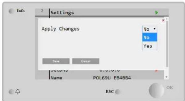
text_image
Info 2: Settings Apply Changes No No Yes Save Cancel SETD40 0.0.0.0 Name POL69U EB4BB4 ESC OKThe default internet configuration is:
| Parameter | Default Value |
| IP | 192.168.1.42 |
| Mask | 255.255.255.0 |
| Gateway | 192.168.1.1 |
| PrimDNS | 0.0.0.0 |
| ScndDNS | 0.0.0.0 |
Note that if the DHCP is set to On and the MT4 internet configurations shows the following parameter values
| Parameter | Value |
| IP | 169.254.252.246 |
| Mask | 255.255.0.0 |
| Gateway | 0.0.0.0 |
| PrimDNS | 0.0.0.0 |
| ScndDNS | 0.0.0.0 |
then an internet connection problem has occurred (probably due to a physical problem, like the Ethernet cable breaking).
4.13 Daikin On Site
The Daikin on Site (DoS) page can be accessed navigating through Main Menu → View/Set Unit → Daikin On Site.

text_image
Info View/Set Unit Electrical Data Evaporator Flow Scheduler Date/Time Controller IP Setup Daikin on Site Settings Change History Menu Password
text_image
Info 1 Daikin on Site Comm Start Off Comm State - Serial Number 614 Remote Update Disable Activation Key DSFJNJ-H37NP-UHJPA-RQEOD-I4HL ICCID:To use the DoS utility, the customer must communicate the Serial Number to Daikin company and subscribe to the DoS service. Then, from this page, it is possible to:
- Start/Stop the DoS connectivity
- Check the connection status to DoS service
- Enable/Disable the remote update option
according to the parameters shown into the table below.
| Parameter | Range | Description |
| Comm Start | off | Stop the connection to DoS |
| Start | Start the connection to DoS | |
| Comm State | - | Connection to DoS is off |
| IPErr | Connection to DoS cannot be established | |
| Connected | Connection to DoS is established and working | |
| Remote Update | Enable | Enable the Remote update option |
| Disable | Disable the Remote update option |
Among all the services provided by DoS, the Remote Update option allows to remotely update the software currently running on the PLC controller, avoiding an in-situ intervention of maintenance personnel. To this purpose, just set the Remote Update parameter to Enable. Otherwise, keep the parameter set to Disable.
In the unlikely event of PLC replacement, the DoS connectivity can be switched from the old PLC to the new one just communicating the current Activation Key to Daikin company.

For a successful remote software update, local service support is required, and a strong internet connection must be guaranteed.
4.14 Heat Recovery
The unit controller can handle a total or partial heat recovery option.
Some settings need to be properly set to match the specific plant requirements, going in Main Page > View/Set Unit > Heat Recovery.
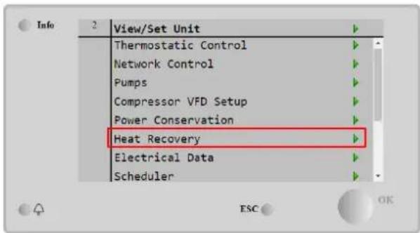
text_image
Info 2 View/Set Unit Thermostatic Control Network Control Pumps Compressor VFD Setup Power Conservation Heat Recovery Electrical Data Scheduler
text_image
Info 1 Heat Recovery HR State Recirculation HR C1 Enable Disable HR C2 Enable Disable HR Network Enable Disable HR LWT -273.1°C HR EWT -273.1°C HR EWT Sp 40.0°C HR EWT Dif 2.0°C ESC OK| Parameter | Range | Description |
| HR State | Off | Heat recovery is disabled |
| Recirculation | Heat recovery pump is running, but chiller fan is not regulating the heat recovery water temperature | |
| Regulation | Heat recovery pump is running and chiller fans are regulating the heat recovery water temperature | |
| HR C1 Enable | Disable | Heat Recovery on C1 is disabled |
| Enable | Heat Recovery on C1 is enabled | |
| HR C2 Enable | Disable | Heat Recovery on C2 is disabled |
| Enable | Heat Recovery on C2 is enabled | |
| HR Network Enable | Disable | The Heat Recovery is disabled by Network |
| Enable | The Heat Recovery is enabled by Network | |
| HR LWT | Heat recovery leaving water temperature | |
| HR EWT | Heat recovery entering water temperature | |
| HR EWT Sp | Heat recovery entering water temperature setpoint value | |
| HR EWT Dif | Heat recovery | |
| HR Lock Limit | Heat Recovery Lock Limit | |
| HR Delta Sp | Heat Recovery Delta Setpoint | |
| HR 3-Way Valve | Heat recovery 3-way valve opening percentage | |
| HR Pumps | Heat recovery pump state | |
| HR Pump Hours | Heat recovery pump running hours |
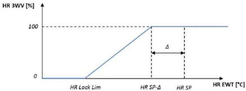
line
| HR EWT [°C] | HR 3WV [%] | | ----------- | ---------- | | HR Lock Lim | 0 | | HR SP-Δ | 100 | | HR SP | 100 |In case unit control source is "Network", to enable heat recovery functionality following conditions must be true:
- Enable the "HR C1 or C2 Enable" parameter in the Heat recovery page.
- Enable BMS register: Heat Recovery - Enable Setpoint
4.15 Rapid Restart
This chiller can activate a Rapid Restart (optional) sequence in reaction to a power failure. A digital contact is used to inform the controller that the feature is enabled. The feature is configured in the factory.
text_image
Info 4 View/Set Unit Thermostatic Control Network Control Pumps Compressor VFD Setup Power Conservation Rapid Restart Scheduler Date/Time ESC OK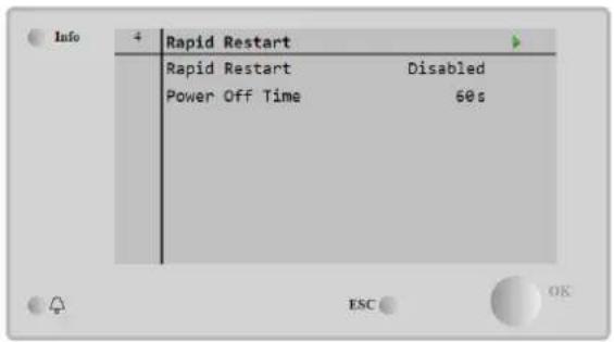
text_image
Info 4 Rapid Restart Rapid Restart Disabled Power Off Time 60s ESC OKRapid restart is activated under the following conditions:
• The power failure exists for up to 180 seconds
• The unit and circuit switches are ON
- No unit or circuit alarms exist
• The unit has been running in the normal Run state
• The BMS Circuit Mode setpoint is set to Auto when the control source is Network
If the power failure is more than 180 seconds, the unit will start based on the setting of the Stop-to-Start cycle timer (minimum setting of 3 minutes) and load per standard unit without Rapid Restart.
When Rapid Restart is active, the unit will restart within 30 seconds of power restoration. The time to restore full load is less than 3 minutes.
4.16 FreeCooling Hydronic (Cooling Only)
Freecooling is started when the outside air temperature is lower than the entering water temperature by a predetermined freecooling delta T. Full freecooling will only be possible below a design temperature however logic will try to get the most out of the air temperature to optimize the overall performance of the chiller.
When freecooling is started, the freecooling valve is opened to let water pass through the freecooling coils and get cooled before entering the evaporator heat exchanger and go to the plant as leaving water temperature. Fans are started and then controlled to maintain the leaving water temperature to the active setpoint.
If the outside air temperature is not low enough to permit full freecooling and satisfy the plant load, the unit may start the mixed mode. In fact, if, with the fan at full speed, the leaving water temperature does not reach the active setpoint and remains above the Stage Up Temperature with a low slope, after a predetermined time a circuit can be started in mechanical mode. In this case, the fan speed will be adapted to control the minimum pressure ratio needed to guarantee the correct lubrication of compressors.

text_image
Info 1 View/Set Unit Compressor VFD Setup Power Conservation Hydronic FreeCooling Scheduler Date/Time Controller IP Setup Daikin on Site Settings Change History ESC OK
text_image
Info 1 FreeCooling Input Disable Remote Input Disable State Off FC Max OAT 24.0°C FC Delta T 4.0°C FC Min VFD Sp 0% FC Max VFD Sp 86% FC Prop Gain 5.0°C| Parameter | Range | Description |
| Input | Disable | The Option is not enabled with all the inputs necessary |
| Enable | The Option is correctly enabled | |
| Remote Input | Disable | The Remote Input is not enabled with all the inputs necessary |
| Enable | The Remote Input is correctly enabled | |
| State | off | Unit's State in Off |
| Free Cooling | Unit State in Free Cooling mode, both Circuits run in Freecooling | |
| Mixed | Unit State in Mixed mode, one Circuit run in Freecooling and the second run in Mechanical mode | |
| Mechanical | Unit State in Mechanical mode, both Circuits run in Mechanical | |
| FC Max Oat | 10-30 °C | Maximum value for air temperature to enable the freecooling. Above this value the freecooling mode cannot be used. |
| FC Delta T | 0-10 °C | Difference between entering water temperature and air temperature to enable the freecooling operations. |
| FC Min Pr | 1.4-3 | To adjust minimum pressure ratio for fans control. |
| FC Max Pr | 1.4-3 | To adjust maximum pressure ratio for fans control. |
| FC Min VFD Sp | 5-50 % | To adjust minimum fan speed in freecooling mode. |
| FC Max VFD Sp | 70-100 % | To adjust maximum fan speed in freecooling mode. |
In order to enable the Freecooling functionality, the customer must set to Enable the "Input" parameter in the Freecooling page.
In case unit control source is "Network", to enable freecooling functionalities following conditions must be true:
1) Enable the "Input" parameter in the Freecooling page.
2) Enable BMS register: Freecooling - Enable Setpoint
4.16.1 Glycol Free Freecoling
The Glycol Free option in Freecoling condition is characterized with the presence of an intermediate water/water heat exchanger connected to a water loop with glycol. The main water loop will be glycol free to simplify the waste water
management. This kind of chillers require an additional pump to circulate the glycol in the freecooling closed loop which is linked to the main loop through an intermediate heat exchanger. This pump will be always active when freecooling is active, in case in of freezing in the closed loop or OAT Lockout.
So, in case of glycol free option, there are some additional datapoints respect the hydronic freecooling:

text_image
Info 1 View/Set Unit Compressor VFD Setup Power Conservation Hydronic FreeCooling Scheduler Date/Time Controller IP Setup Daikin on Site Settings Change History ESC OK Info 4 FreeCooling FC Max OAT 24.0°C FC Delta T 4.0°C FC Min VFD Sp 23% FC Max VFD Sp 86% Glycol Pmp Spd 100% Glycol Pmp Act Spd 0% Glycol Nom PD 10kPa Glycol Min Freq 30Hz ESC OK| Parameter | Range | Description |
| Glycol Pmp Spd | 0-100 % | Select nominal glycol pump's speed |
| Glycol Pmp Act Spd | 0-100 % | Show the actual velocity of the glycol pump |
| Glycol Nom PD | 1-200 kPa | Select nominal evaporator pressure drop corresponding at the rated flow rate |
| Glycol Min Freq | 1-40 Hz | Select the minimum frequency of the glycol pump |
| Glycol DT OFS | 0-15 °C | Select the additional offset to the Fc Delta T to enable the freecooling operations (during the transition mechanical Fc to mixed Fc) |
4.17 Antifreeze Heater
The Antifreeze Heater page can be accessed navigating through Main Menu → View/Set Unit → AntifreezeHeater

text_image
Info 1 View/Set Unit Thermostatic Control Network Control Pumps AntiFrz Heater Glycol Tank Heater Compressor VFD Setup Power Conservation Hydronic FreeCooling ESC OK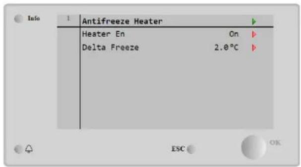
text_image
Info 1 Antifreeze Heater Heater En On Delta Freeze 2.0°C ESC OK| Parameter | Range | Description |
| Heater En | off | The Option is not enabled. |
| on | The Option is correctly enabled | |
| Delta Freeze | -5 ÷ +5^ | Difference between entering or leaving water temperature and freezing setpoint to enable the antifreeze heater. |
In order Enable the Antifreeze Heater functionality, the customer must set to On the "Heater En" parameter in the Antifreeze Heater page.
4.18 Glycol Tank Heater
The Glycol Tank Heater page can be accessed navigating through Main Menu → View/Set Unit → Glycol Tank Heater
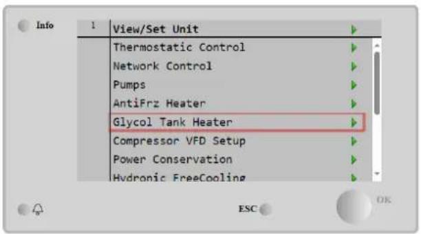
text_image
Info 1 View/Set Unit Thermostatic Control Network Control Pumps AntiFrz Heater Glycol Tank Heater Compressor VFD Setup Power Conservation Hydronic FreeCooling ESC OK
text_image
Info 1 Glycol Tank Heater Heater En On Delta Freeze 2.0°C ESC OK| Parameter | Range | Description |
| Heater En | Off | The Option is not enabled. |
| On | The Option is correctly enabled | |
| Delta Freeze | -5 ÷ +5^ | Difference between glycol entering or glycol leaving water temperature and glycol tan freezing setpoint to enable the glycol tank heater. |
In order Enable the Glycol Tank Heater functionality, the customer must set to On the "Heater En" parameter in the Glycol Tank Heater page.
4.19 Harmonic Filter (SAF)
The Harmonic Filter (SAF) page can be accessed navigating through Main Menu → View/Set Unit → Harmonic Filter.
The active harmonic filter is a power quality device that dynamically delivers a controlled current that has the same amplitude as the harmonic current, which is injected in opposition to the harmonics present. This cancels the harmonic currents in the electrical system.
text_image
Info 1 View/Set Unit Compressor VFD Setup Power Conservation Heat Recovery HarmonicFilter Hydronic FreeCooling Scheduler Date/Time Controller IP Setup
text_image
Info 1 Harmonic Filter Filter On On State PwrOff Clr Tmr Off Cmd Fdbk Off Reg Temp 0.0°C Cool Plate Temp 0.0°C Cool Duty Cycle 0.0 Grid Voltage 0V ESC OK| Parameter | Range | Description |
| Filter On | Off | The Option is not enabled. |
| On | The Option is correctly enabled. | |
| State | PwrOff | Power off (Waiting main supply) |
| waitSSCmd | Waiting soft start command | |
| SSCmdOn | Soft start command On | |
| PreCOn | Capacitors pre charge On | |
| PreCEnd | Capacitors pre charge End | |
| WaitRun | Waiting Run | |
| Run | SAF runs | |
| SAFAlms | SAF generic Alarms | |
| PCAlms | SAF Pre charge alarms | |
| NoState | No state available | |
| Clr Tmr | off | Clear Timer Off |
| on | Clear Timer On | |
| Cmd Fdbk | off | Command feedback Off |
| on | Command feedback On | |
| Reg Temp | °C | Regulation Card temperature |
| Cool Plate Temp | °C | SAF cooling plate temperature |
| Cool Duty Cycle | SAF cooling plate valve duty cycle | |
| Grid voltage | V | Grid voltage |
| Grid THDi | % | Grid total harmonic distorsion (current) |
| Grid TDD | % | Grid total demand distorsion |
| Grid THDv | % | Grid total harmonic voltage distorsion |
| TDDi Ref | % | Total demand distorsion reference |
| Rel Hum | %real Hum | Related humidity sensor |
| Dew Temp | °C | Dew temperature calculated due the related humidity sensor |
| TbAF | °C | Temperature bottom sensor LH filter side |
| TbPLC | °C | Temperature bottom sensor PLC side |
| Tt1AF | °C | Temperature top 1 sensor LH filter side |
| Tt2AF | °C | Temperature top 2 sensor LH filter side |
| TtPLC | °C | Temperature top sensor PLC side |
| Compensation | Showed in related menu all the single compressor harmonics |
Main Menu → view/Set Unit → Harmonic Filter → Compensation

text_image
Info 4 Compensation Harmonic 2 0.000 Harmonic 3 0.000 Harmonic 5 0.000 Harmonic 7 0.000 Harmonic 11 0.000 Harmonic 13 0.000 Harmonic 17 0.000 Harmonic 19 0.000 ESC OKIn order Enable the SAF functionality, the customer must set to On the "Filter On" parameter in the Harmonic Fitler page.
4.20 Software Options
The possibility to employ a set of software options has been added to the functionality of the chiller, in according with Microtech 4 installed on the Unit. The Software Options do not require any additional hardware and regard communication channels and the new energy functionalities.
During the commissioning the machine is delivered with the Option Set chosen by the customer; the Password inserted is permanent and depends on the Serial Machine Number and the Option Set selected.
To check the current Option Set:
Main Menu→Commission Unit→Configuration→Software Options
text_image
Info Configuration Unit Circuit 1 Options Software Options
text_image
Info 2 Software Options Apply Changes No Password 0123456789012 1-Modbus Slave MSTP On 1-State On 2-BACNet MSTP Off 2-State Off 3-BACNet IP Off 3-State Off ESC OK| Parameter | Description |
| Password | Writable by Interface/Web Interface |
| Option Name | Option Name |
| option | Option is activated. |
| Status | Option is not activated |
The Current Password inserted activates the selected options.
4.20.1 Changing the Password for buying new Software Options
The Option Set and the Password are updated in the Factory. If the customer wants to change its Option Set, he needs to contact the Daikin Personnel and asks for a new password.
As soon as the new password is communicated, the follow steps allow the customer to change the Option Set by himself:
- Wait for the circuits are both OFF, then, from the Main Page, Main Menu→Unit Enable→Unit→Disable
- Go to Main Menu→Commission Unit→Configuration→Software Options
- Select the Options to Activate
- Insert the Password
- Wait for the States of the selected options going to On
- Apply Changes→Yes (it will reboot the controller)

The Password is changeable only if the machine is working in safe conditions: both the circuits are in the State Off.
4.20.2 Inserting the Password in a Spare Controller
If the Controller is broken and/or it needs to be replaced for any reason, the customer needs to configure the Option Set with a new Password.
If this replacement is scheduled, the customer can ask to Daikin Personnel for a new Password.
If there is not enough time to ask for a Password to Daikin Personnel (ex. an expected failure of the controller), a set of Free Limited Password is provided, in order not to interrupt the machine's working.
These Passwords are free and visualized in:
Main Menu→Commission Unit→Configuration→Software Options→Temporary Passwords
text_image
Info 1 Software Options 5-iCM Standard Off 5-State Off 6-iCM Advanced Off 6-State Off 7-Performance Monitoring Off 7-State Off Temporary Passwords Apply Changes No ESC OK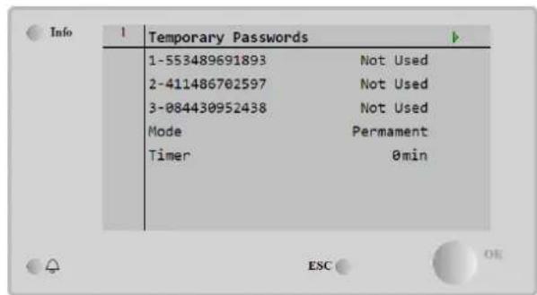
text_image
Info 1 Temporary Passwords 1-553489691893 Not Used 2-411486702597 Not Used 3-084430952438 Not Used Mode Permanent Timer 0minTheir Use is limited up to three months:
• 553489691893 – 3 Months Duration
• 411486702597 – 1 Month Duration
• 084430952438 – 1 Month Duration
It gives the customer the time enough to contact Daikin Service and insert a new unlimited password.
Parameter Specific Status Description
| 553489691893 | Activate the Option Set for 3 Months. | |
| 411486702597 | Activate the Option Set for 1 Month. | |
| 084430952438 | Activate the Option Set for 1 Month. | |
| Mode | Permanent | A permanent Password is inserted. Option set can be used for unlimited time. |
| Temporary | A temporary Password is inserted. Option set can be used depending on the password inserted. | |
| Timer | Last duration of the Option Set activated. Enabled only if the mode is Temporary. |

The Password is changeable only if the machine is working in safe conditions: both the circuits are in the State Off.
4.21 Modbus MSTP
When the software option "Modbus MSTP" is activated and the controller is restarted, the communication protocol settings page can be accessed via the path:
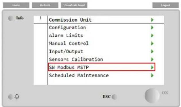
text_image
Name Refresh ShowRate brand Layout Info 1 Commission Unit Configuration Alarm Limits Manual Control Input/Output Sensors Calibration SW Modbus MSTP Scheduled MaintenanceMain Menu→Commission Unit→SW Modbus MSTP
The values that can be set are the same as those found on the Modbus MSTP option page with the relative driver and depend on the specific system where the unit is installed.
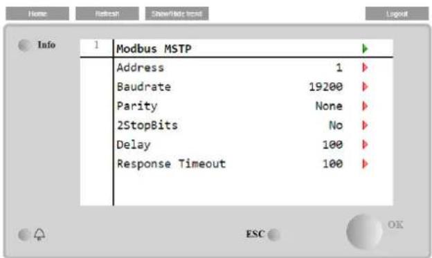
text_image
Info 1 Modbus MSTP Address 1 Baudrate 19200 Parity None 2StopBits No Delay 100 Response Timeout 100 ESC OKTo establish the connection, the RS485 port to use is the one on the T14 terminal of the MT4 controller.


4.22 BACnet MSTP
When the software option "BACNet MSTP" is activated and the controller is restarted, the communication protocol settings page can be accessed via the path:

text_image
Name Release Showfile Event Info 1 Commission Unit Configuration Alarm Limits Manual Control Input/Output Sensors Calibration SW BACNet MSTP Scheduled MaintenanceMain Menu→Commission Unit→SW BACNet MSTP
The values that can be set are the same as those found on the BACNet MSTP option page with the relative driver and depend on the specific system where the unit is installed.
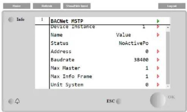
text_image
Info 1 BACNet MSTP Device Instance 1 Name Value Status NoActivePo Address 0 Baudrate 38400 Max Master 1 Max Info Frame 1 Unit System 0 ESC OKTo establish the connection, the RS485 port to use is the one on the T14 terminal of the MT4 controller.

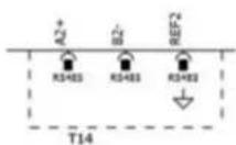
4.23 BACnet IP
When the software option "BACNet IP" is activated and the controller is restarted, the communication protocol settings page can be accessed via the path:
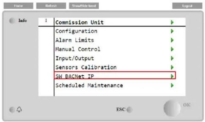
text_image
Info 1 Commission Unit Configuration Alarm Limits Manual Control Input/Output Sensors Calibration SW BACNet IP Scheduled MaintenanceMain Menu→Commission Unit→SW BACNet IP
The values that can be set are the same as those found on the BACNet IP option page with the relative driver and depend on the specific system where the unit is installed.
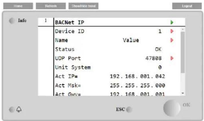
text_image
Home Refresh ShowHide map Info 1 BACNet IP Device ID 1 Name Value Status OK UDP Port 47808 Unit System 0 Act IP= 192.168.001.042 Act Msk= 255.255.255.000 Act GwV= 192.168.001.001 ESC OKThe port for LAN connection to be used for BACNet IP communication is the T-IP Ethernet port, the same one used for remote control of the controller on the PC.
4.24 Energy Monitoring
The Energy Monitoring is a software option not requiring any additional hardware. It can be activated to achieve an estimation (5% accuracy) of the instantaneous performances of the chiller in terms of:
- Cooling Capacity
- Power Input
- Efficiency-COP
An integrated estimation of these quantities is provided. Go to the page:
Main Menu→View / Set Unit→Energy Monitoring
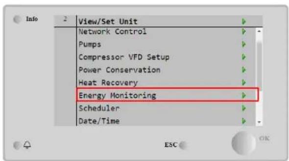
text_image
Info View/Set Unit Network Control Pumps Compressor VFD Setup Power Conservation Heat Recovery Energy Monitoring Scheduler Date/Time
text_image
Info 4 Energy Monitoring Power Input 0.0kW Cooling Capacity 0.0kW EER 0.0 Integrated PI 0.0MWh Integrated CC 0.0MWh Integrated EER 0.0 ESC OK
text_image
Info 2 Power Input Circuit 1 0.0kW Circuit 2 0.0kW ESC OK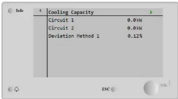
text_image
Info 4 Cooling Capacity Circuit 1 0.0kW Circuit 2 0.0kW Deviation Method 1 0.12% ESC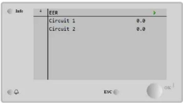
text_image
Info 4 EER Circuit 1 0.0 Circuit 2 0.0 ESCThe UC protects the unit and the components from operating in abnormal conditions. Protections can be divided in preventions and alarms. Alarms can then be divided in pump-down and rapid stop alarms. Pump-down alarms are activated when the system or sub-system can perform a normal shutdown despite the abnormal running conditions. Rapid stop alarms are activated when the abnormal running conditions require an immediate stop of the whole system or sub-system to prevent potential damages.
The UC displays the active alarms in a dedicated page and keep an history of the last 50 entries divided between alarms and acknowledges occurred. Time and date for each alarm event and of each alarm acknowledge are stored.
The UC also stores alarm snapshot of each alarm occurred. Each item contains a snapshot of the running conditions right before the alarm has occurred. Different sets of snapshots are programmed corresponding to unit alarms and circuit alarms holding different information to help the failure diagnosis.
In the following sections it will also be indicated how each alarm can be cleared between local HMI, Network (by any of the high-level interfaces Modbus, Bacnet or Lon) or if the specific alarm will clear automatically. The following symbols are used:
| ☑ | Allowed |
| ☒ | Not allowed |
| ☐ | Not foreseen |
5.1 Unit Alerts
5.1.1 Bad Current Limit Input
This alarm is generated when the Flexible Current Limit option has been enabled and the input to the controller is out of the admitted range.
| Symptom | Cause | Solution |
| Unit status is Run.Bell icon is moving on controller's display.Flexible Current Limit function cannot be used.String in the alarm list:BadCurrentLimitInputString in the alarm log:± BadCurrentLimitInputString in the alarm snapshotBadCurrentLimitInput | Flexible current limit input out of range.For this warning out of range is a signal less than 3mA or more than 21mA. | Check for values of input signal to the unit controller. It has to be in the allowed mA range. |
| Check for electrical shielding of wirings. | ||
| Check for right value of the unit's controller output in case input signal is into allowed range. | ||
| Reset | Notes | |
| Local HMINetworkAuto | ☐☐☑ | Automatically clears when the signal returns in the allowed range. |
5.1.2 Option1BoardCommFail – Optional board 1 communication fail
This alarm is generated in case of communication problems with the AC module.
| Symptom | Cause | Solution |
| Unit status is Off.All circuits are stopped immediately.Bell icon is moving on controller's display.String in the alarm list:Option1BoardCommFailString in the alarm log:± Option1BoardCommFailString in the alarm snapshotOption1BoardCommFail | Module has no power supply | Check the power supply from the connector on the side of the module. |
| Check if LEDs are both green. | ||
| Check if the connector on the side is tightly inserted in the module | ||
| Led Off | Check if power supply is ok but LEDs are both off. In this case replace the module | |
| BUS or BSP Led are red | Check if module's address is correct referring to the wiring diagram. | |
| If BSP LED is solid red replace the module. | ||
| BSP error. | ||
| Reset | ||
| Local HMINetworkAuto | ☑☑☐ | |
5.1.3 Bad Leaving Water Temperature Reset Input
This alarm is generated when the Setpoint Reset option has been enabled and the input to the controller is out of the admitted range.
| Symptom | Cause | Solution |
| Unit status is Run.Bell icon is moving on controller's display.LWT Reset function cannot be used.String in the alarm list:BadSetPtOverrideInputString in the alarm log:± BadSetPtOverrideInputString in the alarm snapshotBadSetPtOverrideInput | LWT reset input signal is out of range.For this warning out of range is a signal less than 3mA or more than 21mA. | Check for values of input signal to the unit controller. It has to be in the allowed mA range. |
| Check for electrical shielding of wirings. | ||
| Check for right value of the unit's controller output in case input signal is into allowed range. | ||
| Reset | Notes | |
| Local HMINetworkAuto | ☐☐☑ | Automatically clears when the signal returns in the allowed range. |
5.1.4 Energy Meter Communication Fail
This alarm is generated in case of communication problems with the energy meter.
| Symptom | Cause | Solution |
| Bell icon is moving on controller's display.String in the alarm list:EnrgMtrCommFailString in the alarm log:± EnrgMtrCommFailString in the alarm snapshotEnrgMtrCommFail | Module has no power supply | Refer to the datasheet of the specific component to see if it is correctly powered |
| Wrong cabling with the Unit Controller | Check if the polarity of the connections is respected. | |
| Modbus parameters not properly set | Referring to the datasheet of the specific component to see if the modbus parameters are set correctly:Address = 20Baud Rate =19200 kBsParity = NoneStop bits =1 | |
| Module is broken | Check if the display shows something and the power supply is present. | |
| Reset | Notes | |
| Local HMINetworkAuto | ☐☐☑ | Automatically clears when the communication is re-established. |
5.1.5 Evaporator Pump #1 Failure
This alarm is generated if the pump is started but the flow switch is not able to close within the recirculate time. This can be a temporary condition or may be due to a broken flow switch, the activation of circuit breakers, fuses or to a pump breakdown.
| Symptom | Cause | Solution |
| Unit could be ON.Bell icon is moving on controller's display.Backup pump is used or stop of all circuits in case of pump #2 failure.String in the alarm list:EvapPump1FaultString in the alarm log:± EvapPump1FaultString in the alarm snapshotEvapPump1Fault | Pump #1 may not be operating. | Check for problem in electrical wiring of the pump #1. |
| Check that electrical breaker of pump #1 is tripped. | ||
| If fuses are used to protect the pump, check the integrity of fuses. | ||
| Check for problem in wiring connection between pump starter and unit controller. | ||
| Check the water pump filter and the water circuit for obstructions. | ||
| Flow Switch doesn't operate properly | Check flow switch connection and calibration. | |
| Reset | Notes | |
| Local HMINetworkAuto | ☑☑☐ |
5.1.6 Evaporator Pump #2 Failure
This alarm is generated if the pump is started but the flow switch is not able to close within the recirculate time. This can be a temporary condition or may be due to a broken flowswitch, the activation of circuit breakers, fuses or to a pump breakdown.
| Symptom | Cause | Solution |
| Unit could be ON.Bell icon is moving on controller's display.Backup pump is used or stop of all circuits in case of pump #1 failure.String in the alarm list:EvapPump2FaultString in the alarm log:± EvapPump2FaultString in the alarm snapshotEvapPump2Fault | Pump #2 may not be operating. | Check for problem in electrical wiring of the pump #2. |
| Check that electrical breaker of pump #2 is tripped. | ||
| If fuses are used to protect the pump, check the integrity of fuses. | ||
| Check for problem in wiring connection between pump starter and unit controller. | ||
| Check the water pump filter and the water circuit for obstructions. | ||
| Flow Switch doesn't operate properly | Check flow switch connection and calibration. | |
| Reset | Notes | |
| Local HMINetworkAuto | ☑☑☐ |
5.1.7 External Event
This alarm indicates that a device, whose operation is linked with this machine, is reporting a problem on the dedicated input.
| Symptom | Cause | Solution |
| Unit status is Run.Bell icon is moving on controller's display.String in the alarm list:UnitExternalEventString in the alarm log:±UnitExternalEventString in the alarm snapshotUnitExternalEvent | There is an external event that has caused the opening, for at least 5 seconds of the digital input on the controller board. | Check for reasons of external event and if it can be a potential problem for a correct chiller operation. |
| Reset | Notes | |
| Local HMINetworkAuto | ☐☐☑ | The alarm is automatically cleared when the problem is solved. |
| NOTE: What above applies in case of configuration of the external fault digital input as Event | ||
5.1.8 Password Over Time
| Symptom | Cause | Solution |
| Pass1TimeOver 1dayleft | Temporary Password Inserted is going to expire. One day is left before Option set becomes inactive. | Insert a new password |
| Pass2TimeOver 1dayleft | ||
| Pass3TimeOver 1dayleft | ||
| Reset | Notes | |
| Local HMI | ☑ | |
| Network | ☑ | |
| Auto | ☑ |
5.1.9 Heat Recovery Entering Water Temperature sensor fault
This alarm is generated any time that the input resistance is out of an acceptable range.
| Symptom | Cause | Solution |
| Unit status is Off.All circuits are stopped with a normal shutdown procedure.Bell icon is moving on controller's display.String in the alarm list:UnitAlHREwtSenString in the alarm log:± UnitAlHREwtSenString in the alarm snapshotUnitAlHREwtSen | Sensor is broken. | Check for sensor integrity according to table and allowed kOhm (kΩ) range. |
| Check correct sensors operation | ||
| Sensor is shorted. | Check if sensor is shorted with a resistance measurement. | |
| Sensor is not properly connected (open). | Check for absence of water or humidity on electrical contacts. | |
| Check for correct plug-in of the electrical connectors. | ||
| Check for correct sensors wiring also according electrical scheme. | ||
| Reset | Notes | |
| Local HMINetworkAuto | ☑☑☐ |
5.1.10 Heat Recovery Leaving Water Temperature sensor fault
This alarm is generated any time that the input resistance is out of an acceptable range.
| Symptom | Cause | Solution |
| Heat Recovery is OffBell icon is moving on controller's display.String in the alarm list:UnitAlHRLwtSenString in the alarm log:± UnitAlHRLwtSenString in the alarm snapshotUnitAlHRLwtSen | Sensor is broken. | Check for sensor integrity according to table and allowed kOhm (kΩ) range. |
| Check correct sensors operation | ||
| Sensor is shorted. | Check if sensor is shorted with a resistance measurement. | |
| Sensor is not properly connected (open). | Check for absence of water or humidity on electrical contacts. | |
| Check for correct plug-in of the electrical connectors. | ||
| Check for correct sensors wiring also according to electrical scheme. | ||
| Reset | Notes | |
| Local HMINetworkAuto | ☑☑☐ |
5.1.11 Heat Recovery Water Temperatures inverted
This alarm is generated any time that the heat recovery entering water temperature is lower than the leaving by 1^ C and at least one compressor is running.
| Symptom | Cause | Solution |
| Bell icon is moving on controller's display.Bell icon is moving on controller's display.String in the alarm list:Unit HRInvAlString in the alarm log:± Unit HRInvAlString in the alarm snapshotUnit HRInvAl | Entering and leaving water temperature sensors are inverted. | Check cabling of the sensors on the unit controller. |
| Check offset of the two sensors with the water pump running | ||
| Entering and leaving water pipes are reversed | Check if the water flows in counter flow respect to refrigerant. | |
| Water pumps operate reverse. | Check if the water flows in counter flow respect to refrigerant. | |
| Reset | Notes | |
| Local HMINetworkAuto | ☑☑☐ |
5.1.12 Evaporator differential pressure transducer sensor fault
This alarm is generated any time the differential pressure transducer on the evaporator is broken.
| Symptom | Cause | Solution |
| Unit status is OnBell icon is moving on controller's display.String in the alarm list:EvapPDSenString in the alarm log:± EvapPDSenString in the alarm snapshotEvapPDSen | Sensor is broken. | Check for sensor integrity according to table and allowed Volts or Amps range. |
| Check correct sensors operation | ||
| Sensor is shorted. | Check if sensor is shorted with a resistance measurement. | |
| Sensor is not properly connected (open). | Check for absence of water or humidity on electrical contacts. | |
| Check for correct plug-in of the electrical connectors. | ||
| Check for correct sensors wiring also according to electrical scheme. | ||
| Reset | Notes | |
| Local HMINetworkAuto | ☑☑☐ |
5.1.13 System load differential pressure transducer sensor fault
This alarm is generated any time the differential pressure transducer on the evaporator is broken.
| Symptom | Cause | Solution |
| Unit status is OnBell icon is moving on controller's display.String in the alarm list:LoadPDSenString in the alarm log:± LoadPDSenString in the alarm snapshotLoadPDSen | Sensor is broken. | Check for sensor integrity according to table and allowed Volts or Amps range. |
| Check correct sensors operation | ||
| Sensor is shorted. | Check if sensor is shorted with a resistance measurement. | |
| Sensor is not properly connected (open). | Check for absence of water or humidity on electrical contacts. | |
| Check for correct plug-in of the electrical connectors. | ||
| Check for correct sensors wiring also according to electrical scheme. | ||
| Reset | Notes | |
| Local HMINetworkAuto | ☑☑☐ |
5.1.14 Switch Box Temperature High
This alarm is generated any time the switch box internal temperature exceeds a predetermined limit.
| Symptom | Cause | Solution |
| Unit status is OnBell icon is moving on controller's display.String in the alarm list:SwitchBoxTAlmString in the alarm log:± SwitchBoxTAlmString in the alarm snapshotSwitchBoxTAlm | Insufficient switchbox cooling | Check if the cooling fan is working properly |
| Check if the air filters are clean and there is no obstacle to a proper air flow. | ||
| Outside air temperature above the operating envelope of the unit. | Please refer to the operating envelope of the unit to avoid possible faults or damages to the unit. | |
| Reset | Notes | |
| Local HMINetworkAuto | ☑☑☐ |
5.1.15 Switch Box Temperature sensor fault
This alarm is generated any time that the input resistance is out of an acceptable range.
| Symptom | Cause | Solution |
| Unit status is OnBell icon is moving on controller's display.Bell icon is moving on controller's display.String in the alarm list:SwitchBoxTSenString in the alarm log:± SwitchBoxTSenString in the alarm snapshotSwitchBoxTSen | Sensor is broken. | Check for sensor integrity according to table and allowed kOhm (kΩ) range. |
| Check correct sensors operation | ||
| Sensor is shorted. | Check if sensor is shorted with a resistance measurement. | |
| Sensor is not properly connected (open). | Check for absence of water or humidity on electrical contacts. | |
| Check for correct plug-in of the electrical connectors. | ||
| Check for correct sensors wiring also according to electrical scheme. | ||
| Reset | Notes | |
| Local HMINetworkAuto | ☑☑☐ |
5.1.16 Glycol leaving water temperature sensor fault
This alarm is generated any time that the input resistance is out of an acceptable range.
| Symptom | Cause | Solution |
| Unit status is OnBell icon is moving on controller's display.Bell icon is moving on controller's display.String in the alarm list:Unit GlycollVgwTempString in the alarm log:± Unit GlycollVgwTempString in the alarm snapshotUnit GlycollVgwTemp | Sensor is broken. | Check for sensor integrity according to table and allowed kOhm (kΩ) range. |
| Check correct sensors operation | ||
| Sensor is shorted. | Check if sensor is shorted with a resistance measurement. | |
| Sensor is not properly connected (open). | Check for absence of water or humidity on electrical contacts. | |
| Check for correct plug-in of the electrical connectors. | ||
| Check for correct sensors wiring also according to electrical scheme. | ||
| Reset | Notes | |
| Local HMINetworkAuto | ☐☐☐☑ | Automatically clears when the communication is re-established. |
5.1.17 Glycol entering water temperature sensor fault
This alarm is generated any time that the input resistance is out of an acceptable range.
| Symptom | Cause | Solution |
| Unit status is OnBell icon is moving on controller's display.Bell icon is moving on controller's display.String in the alarm list: | Sensor is broken. | Check for sensor integrity according to table and allowed kOhm (kΩ) range. |
| Check correct sensors operation | ||
| Sensor is shorted. | Check if sensor is shorted with a resistance measurement. | |
| Unit GlycolEntwTempString in the alarm log:± Unit GlycolEntTempString in the alarm snapshotUnit GlycolEntwTemp | Sensor is not properly connected(open). | Check for absence of water orhumidity on electrical contacts. |
| Check for correct plug-in of theelectrical connectors. | ||
| Check for correct sensors wiring alsoaccording to electrical scheme. | ||
| Reset | Notes | |
| Local HMINetworkAuto | □□☑ | Automatically clears when thecommunication is re-established. |
5.1.18 Glycol module communication fail
This alarm is generated in case of communication problems with the module related to the glycol free.
| Symptom | Cause | Solution |
| Unit is on.Bell icon is moving on controller's display.String in the alarm list:GlycolModuleCommFailString in the alarm log:± GlycolModuleCommFailString in the alarm snapshotGlycolModuleCommFail | Module has no power supply | Check the power supply from the connector on the side of the module. |
| Check if LEDs are both green. | ||
| Check if the connector on the side is tightly inserted in the module | ||
| Led Off | Check if power supply is ok but LEDs are both off. In this case replace the module | |
| BUS or BSP Led are red | Check if module's address is correct referring to the wiring diagram. | |
| If BSP LED is solid red replace the module. | ||
| BSP error. | ||
| Reset | Notes | |
| Local HMINetworkAuto | ☐☐☑ | Automatically clears when the communication is re-established. |
5.1.19 Glycol pump communication fail
This alarm is generated in case of Modbus communication problems with glycol pump.
| Symptom | Cause | Solution |
| Bell icon is moving on controller's display.String in the alarm list:GlycolPmpCommFailString in the alarm log:± GlycolPmpCommFailString in the alarm snapshotGlycolPmpCommFail | RS485 network is not properly cabled. | Check the continuity of the RS485 network with the unit off. There should be continuity from the main controller to the pump as indicated on the wiring diagram. |
| Modbus communication is not running properly. | Check glycol pump address. All the addresses must be different. | |
| Glycol pump is not powered | Check if the glycol pump is correctly powered. | |
| Reset | Notes | |
| Local HMINetworkAuto | ☑☑☐ |
5.1.20 Glycol pump alarm
This alarm is generated in case of generic hardware or operating problem with the glycol pump in the closed loop.
| Symptom | Cause | Solution |
| Unit could be ON.Bell icon is moving on controller's display.String in the alarm list:GlycolPmpAlmString in the alarm log:± GlycolPmpAlmString in the alarm snapshotGlycolPmpAlm | Glycol pump may not be operating. | Check for problem in electrical wiring of the glycol pump.. |
| Check that electrical breaker of glycol pump is tripped. | ||
| If fuses are used to protect the glycol pump, check the integrity of fuses. | ||
| Check the glycol pump filter and the glycol water circuit for obstructions. | ||
| Reset | Notes | |
| Local HMI | ☑ | |
| Network | ☑ | |
| Auto | ☐ |
5.1.21 Datacenter module temperature top PLC side sensor fault
This alarm is generated any time that the input resistance is out of an acceptable range.
| Symptom | Cause | Solution |
| Unit status is OnBell icon is moving on controller's display.Bell icon is moving on controller's display.String in the alarm list:DcTtPLC SenfString in the alarm log:± DcTtPLC SenfString in the alarm snapshotDcTtPLC Senf | Sensor is broken. | Check for sensor integrity according to table and allowed kOhm (kΩ) range. |
| Check correct sensors operation | ||
| Sensor is shorted. | Check if sensor is shorted with a resistance measurement. | |
| Sensor is not properly connected (open). | Check for absence of water or humidity on electrical contacts. | |
| Check for correct plug-in of the electrical connectors. | ||
| Check for correct sensors wiring also according to electrical scheme. | ||
| Reset | Notes | |
| Local HMINetworkAuto | ☐☐☑ | Automatically clears when the communication is re-established. |
5.1.22 Datacenter module temperature bottom PLC side sensor fault
This alarm is generated any time that the input resistance is out of an acceptable range.
| Symptom | Cause | Solution |
| Unit status is OnBell icon is moving on controller's display.Bell icon is moving on controller's display.String in the alarm list:DcTbPLC SenfString in the alarm log:± DcTbPLC SenfString in the alarm snapshotDcTbPLC Senf | Sensor is broken. | Check for sensor integrity according to table and allowed kOhm (kΩ) range. |
| Check correct sensors operation | ||
| Sensor is shorted. | Check if sensor is shorted with a resistance measurement. | |
| Sensor is not properly connected (open). | Check for absence of water or humidity on electrical contacts. | |
| Check for correct plug-in of the electrical connectors. | ||
| Check for correct sensors wiring also according to electrical scheme. | ||
| Reset | Notes | |
| Local HMINetworkAuto | ☐☐☑ | Automatically clears when the communication is re-established. |
5.1.23 Datacenter module temperature top 1 LH filter side sensor fault
This alarm is generated any time that the input resistance is out of an acceptable range.
| Symptom | Cause | Solution |
| Unit status is OnBell icon is moving on controller's display.Bell icon is moving on controller's display.String in the alarm list:DcTt1AF SenfString in the alarm log:± DcTt1AF SenfString in the alarm snapshotDcTt1AF Senf | Sensor is broken. | Check for sensor integrity according to table and allowed kOhm (kΩ) range. |
| Check correct sensors operation | ||
| Sensor is shorted. | Check if sensor is shorted with a resistance measurement. | |
| Sensor is not properly connected (open). | Check for absence of water or humidity on electrical contacts. | |
| Check for correct plug-in of the electrical connectors. | ||
| Check for correct sensors wiring also according to electrical scheme. | ||
| Reset | Notes | |
| Local HMINetworkAuto | □□☑ | Automatically clears when the communication is re-established. |
5.1.24 Datacenter module temperature top 2 LH filter side sensor fault
This alarm is generated any time that the input resistance is out of an acceptable range.
| Symptom | Cause | Solution |
| Unit status is OnBell icon is moving on controller's display.Bell icon is moving on controller's display.String in the alarm list:DcTt2AF SenfString in the alarm log:± DcTt2AF SenfString in the alarm snapshotDcTt1AF Senf | Sensor is broken. | Check for sensor integrity according to table and allowed kOhm (kΩ) range. |
| Check correct sensors operation | ||
| Sensor is shorted. | Check if sensor is shorted with a resistance measurement. | |
| Sensor is not properly connected (open). | Check for absence of water or humidity on electrical contacts. | |
| Check for correct plug-in of the electrical connectors. | ||
| Check for correct sensors wiring also according to electrical scheme. | ||
| Reset | Notes | |
| Local HMINetworkAuto | ☐☐☑ | Automatically clears when the communication is re-established. |
5.1.25 Datacenter module temperature bottom LH filter side sensor fault
This alarm is generated any time that the input resistance is out of an acceptable range.
| Symptom | Cause | Solution |
| Unit status is OnBell icon is moving on controller's display.Bell icon is moving on controller's display.String in the alarm list:DcTbAF SenfString in the alarm log:± DcTbAF SenfString in the alarm snapshotDcTbAF Senf | Sensor is broken. | Check for sensor integrity according to table and allowed kOhm (kΩ) range. |
| Check correct sensors operation | ||
| Sensor is shorted. | Check if sensor is shorted with a resistance measurement. | |
| Sensor is not properly connected (open). | Check for absence of water or humidity on electrical contacts. | |
| Check for correct plug-in of the electrical connectors. | ||
| Check for correct sensors wiring also according to electrical scheme. | ||
| Reset | Notes | |
| Local HMINetworkAuto | ☐☐☑ | Automatically clears when the communication is re-established. |
5.1.26 Datacenter module relative humidity sensor fault
This alarm is generated any time that the input resistance is out of an acceptable range.
| Symptom | Cause | Solution |
| Unit status is OnBell icon is moving on controller's display.Bell icon is moving on controller's display.String in the alarm list:DcRe1Hum SenfString in the alarm log:± DcRe1Hum SenfString in the alarm snapshotDcRe1Hum Senf | Sensor is broken. | Check for sensor integrity according to table and allowed mV range. |
| Check correct sensors operation | ||
| Sensor is shorted. | Check if sensor is shorted with a resistance measurement. | |
| Sensor is not properly connected (open). | Check for absence of water or humidity on electrical contacts. | |
| Check for correct plug-in of the electrical connectors. | ||
| Check for correct sensors wiring also according to electrical scheme. | ||
| Reset | Notes | |
| Local HMINetworkAuto | ☐☐☑ | Automatically clears when the communication is re-established. |
5.1.27 Datacenter module communication fail
This alarm is generated in case of communication problems with the datacenter module.
| Symptom | Cause | Solution |
| Unit status is On.Bell icon is moving on controller's display.String in the alarm list: DcModCommFailString in the alarm log: ± DcModCommFailString in the alarm snapshot DcModCommFail | Module has no power supply | Check the power supply from the connector on the side of the module. |
| Check if LEDs are both green. | ||
| Check if the connector on the side is tightly inserted in the module | ||
| Led Off | Check if power supply is ok but LEDs are both off. In this case replace the module | |
| BUS or BSP Led are red | Check if module's address is correct referring to the wiring diagram. | |
| If BSP LED is solid red replace the module. | ||
| BSP error. | ||
| Reset | Notes | |
| Local HMINetworkAuto | ☐☐☑ | Automatically clears when the communication is re-established. |
5.1.28 SAF communication fail
This alarm is generated in case of communication problems with the SAF.
| Symptom | Cause | Solution |
| Bell icon is moving on controller's display.String in the alarm list:SAF CommErrString in the alarm log:± SAF CommErrString in the alarm snapshotSAF CommErr | RS485 network is not properly cabled. | Check the continuity of the RS485 network with the unit off. There should be continuity from the main controller to the SAF as indicated on the wiring diagram. |
| Modbus communication is not running properly. | SAF pump address. All the addresses must be different. | |
| SAF is not powered | Check if the SAF is correctly powered. | |
| Reset | Notes | |
| Local HMINetworkAuto | ☐☐☐☑ | Automatically clears when the communication is re-established. |
5.1.29 SAF High current
This alarm indicates that the SAF current has exceeded a safety limit and it must be stopped to avoid damages to components.
| Symptom | Cause | Solution |
| Bell icon is moving on controller's display.String in the alarm list:SAF HiCurrentString in the alarm log:± SAF HiCurrentString in the alarm snapshotSAF HiCurrent | Filter adsorbed current is exceeding a predefined limit | Contact service organization to check filter integrity. |
| Reset | Notes | |
| Local HMINetworkAuto | ☐☐☑ |
5.1.30 SAF High temperature
This alarm indicates that the SAF temperature has exceeded a safety limit and it must be stopped to avoid damages to components.
| Symptom | Cause | Solution |
| Bell icon is moving on controller's display.String in the alarm list:SAF HiTempString in the alarm log:± SAF HiTempString in the alarm snapshotSAF HiTemp | PTC is being used and its Ohm value has reached the safety threshold. | Check the motor and the PTC thermal probe. |
| Reset | Notes | |
| Local HMINetworkAuto | ☐☐☑ |
5.1.31 SAF High regulation card temperature
This alarm indicates that the SAF regulation card temperature has exceeded a safety limit and it must be stopped to avoid damages to components.
| Symptom | Cause | Solution |
| Bell icon is moving on controller's display.String in the alarm list:SAF HiRegTempString in the alarm log:± SAF HiRegTempString in the alarm snapshotSAF HiRegTemp | Filter regulation card temperature is greater than maximum threshold | Contact service organization to check filter integrity. |
| Reset | Notes | |
| Local HMINetworkAuto | ☐☐☑ |
5.1.32 SAF Under voltage
This alarm indicates that the SAF voltage supply has too low and it must be stopped to avoid damages to components.
| Symptom | Cause | Solution |
| Bell icon is moving on controller's display.String in the alarm list:SAF UnderVtgString in the alarm log:± SAF UnderVtgString in the alarm snapshotSAF UnderVtg | Filter is operating under unsafe condition and for this reason the inverter must be stopped. | Contact service organization to get the problem solved. |
| Reset | Notes | |
| Local HMINetworkAuto | ☐☐☑ |
5.1.33 SAF Over voltage
This alarm indicates that the SAF voltage supply has too high and it must be stopped to avoid damages to components.
| Symptom | Cause | Solution |
| Bell icon is moving on controller's display.String in the alarm list:SAF OverVtgString in the alarm log:± SAF OverVtgString in the alarm snapshotSAF OverVtg | Filter is operating under unsafe condition and for this reason the inverter must be stopped. | Contact service organization to get the problem solved. |
| Reset | Notes | |
| Local HMINetworkAuto | □□□☑ |
5.1.34 SAF Precharge Failure
This alarm indicates that the SAF precharge procedure failed.
| Symptom | Cause | Solution |
| Bell icon is moving on controller's display.String in the alarm list:SAF PreChgFailString in the alarm log:± SAF PreChgFailString in the alarm snapshotSAF PreChgFail | Filter has not been able to complete the precharging phase, before to start the running. | Contact service organization to get the problem solved. |
| Reset | Notes | |
| Local HMINetworkAuto | ☐☐☑ |
5.1.35 SAF Precharge k1 Failure
This alarm indicates that the SAF contactor 1 precharge procedure failed.
| Symptom | Cause | Solution |
| Bell icon is moving on controller's display.String in the alarm list:SAF K1PCFailString in the alarm log:± SAF K1PCFailString in the alarm snapshotSAF K1PCFail | Filter has not been able to complete the precharging phase, before to start the running. | Contact service organization to get the problem solved. |
| Reset | Notes | |
| Local HMINetworkAuto | ☐☐☑ |
5.1.36 SAF Precharge k2 Failure
This alarm indicates that the SAF contactor 2 precharge procedure failed.
| Symptom | Cause | Solution |
| Bell icon is moving on controller's display.String in the alarm list:SAF K2PCFailString in the alarm log:± SAF K2PCFailString in the alarm snapshotSAF K2PCFail | Filter has not been able to complete the precharging phase, before to start the running. | Contact service organization to get the problem solved. |
| Reset | Notes | |
| Local HMINetworkAuto | □□□☑ |
5.1.37 SAF STO Fault
This alarm indicates that the SAF safe torque contact is off. STO contact is linked in series to the other VFDs.
| Symptom | Cause | Solution |
| Bell icon is moving on controller's display.String in the alarm list:SAF STO FaultString in the alarm log:± SAF STO FaultString in the alarm snapshotSAF STO Fault | Filter is operating under unsafe condition and for this reason the inverter must be stopped. | Contact service organization to get the problem solved. |
| Reset | Notes | |
| Local HMINetworkAuto | ☐☐☑ |
5.1.38 SAF STO Fault
This alarm indicates a generic alarm to the SAF (not the previously already mentioned).
| Symptom | Cause | Solution |
| Bell icon is moving on controller's display.String in the alarm list:SAF FaultString in the alarm log:± SAF FaultString in the alarm snapshotSAF Fault | Filter is operating under unsafe condition and for this reason the inverter must be stopped. | Contact service organization to get the problem solved. |
| Reset | Notes | |
| Local HMINetworkAuto | □□✓ |
5.2 Unit Pumpdown Stop Alarms
5.2.1 Evaporator Entering Water Temperature (EWT) sensor fault
This alarm is generated any time the input resistance is out of an acceptable range.
| Symptom | Cause | Solution |
| Unit status is Off.All circuits are stopped with a normal shutdown procedure.Bell icon is moving on controller's display.String in the alarm list:UnitOffEvpEntwTempSenString in the alarm log:± UnitOffEvpEntwTempSenString in the alarm snapshotUnitOffEvpEntwTempSen | Sensor is broken. | Check for sensor integrity according to table and allowed kOhm (kΩ) range. |
| Check correct sensors operation | ||
| Sensor is shorted. | Check if sensor is shorted with a resistance measurement. | |
| Sensor is not properly connected (open). | Check for absence of water or humidity on electrical contacts. | |
| Check for correct plug-in of the electrical connectors. | ||
| Check for correct sensors wiring also according to electrical scheme. | ||
| Reset | Notes | |
| Local HMI Network | ☑☑ |
5.2.2 Evaporator Water Temperatures inverted
This alarm is generated any time the entering water temperature is lower than the leaving by 1^ C and at least one compressor is running for 90 seconds.
| Symptom | Cause | Solution |
| Unit status is Off.All circuits are stopped with a normal shutdown procedure.Bell icon is moving on controller's display.String in the alarm list:UnitOffEvpWTempInvrtdString in the alarm log:± UnitOffEvpWTempInvrtdString in the alarm snapshotUnitOffEvpWTempInvrtd | Entering and leaving water temperature sensors are inverted. | Check cabling of the sensors on the unit controller. |
| Check offset of the two sensors with the water pump running | ||
| Entering and leaving water pipes are reversed | Check if the water flows in counter flow respect to refrigerant. | |
| Water pumps operate reverse. | Check if the water flows in counter flow respect to refrigerant. | |
| Reset | Notes | |
| Local HMINetworkAuto | ☑☑☐ |
5.2.3 Outside Air Temperature (OAT) Lockout
This alarm prevents the unit to start if the outside air temperature is too low. Purpose is to prevent low pressure trips at startup. The limit depends on the fan regulation that is installed on the unit. By default, this value is set to 10^ C.
| Symptom | Cause | Solution |
| Unit Status is OAT Lockout.All circuits are stopped with a normal shutdown procedure.Bell icon is moving on controller's display.String in the alarm list:StartInhbtAmbTempLoString in the alarm log:± StartInhbtAmbTempLoString in the alarm snapshotStartInhbtAmbTempLo | Outside ambient temperature is lower than value set into unit's controller. | Check the minimum outside ambient temperature value set into the unit's controller. |
| Check if this value is in accordance with chiller application, therefore check about the proper application and utilization of the chiller. | ||
| Improper operation of Outside Ambient Temperature sensor. | Check for proper operation of OAT sensor according to information about kOhm (kΩ) range related to temperature values. | |
| Reset | Notes | |
| Local HMINetworkAuto | ☐☐☐☑ | It clears automatically with a 2.5°C of hysteresis. |
5.2.4 Outside Air Temperature sensor fault alarm
This alarm is generated any time the input resistance is out of an acceptable range.
| Symptom | Cause | Solution |
| Unit status is Off.All circuits are stopped with a normal shutdown procedure.Bell icon is moving on controller's display.String in the alarm list:UnitOffAmbTempSenString in the alarm log:± UnitOffAmbTempSenString in the alarm snapshotUnitOffAmbTempSen | Sensor is broken. | Check for sensor integrity. |
| Check correct sensors operation according to table and allowed kOhm (kΩ) range. | ||
| Sensor is shorted. | Check if sensor is shorted with a resistance measurement. | |
| Sensor is not properly connected (open). | Check for absence of water or humidity on electrical contacts. | |
| Check for correct plug-in of the electrical connectors. | ||
| Check for correct sensors wiring also according to electrical scheme. | ||
| Reset | Notes | |
| Local HMINetworkAuto | ☑☑☐ |
5.3 Unit Rapid Stop Alarms
5.3.1 Emergency Stop
This alarm is generated any time the Emergency Stop button is activated.

Before resetting the Emergency Stop button please verify that the harmful condition has been removed.
| Symptom | Cause | Solution |
| Unit status is Off.All circuits are stopped immediately.Bell icon is moving on controller's display.String in the alarm list:UnitOffEmergencyStopString in the alarm log:± UnitOffEmergencyStopString in the alarm snapshotUnitOffEmergencyStop | Emergency stop button has been pushed. | Turning counterclockwise the emergency stop button, the alarm should be cleared. |
| Reset | Notes | |
| Local HMI | ☑ | Please see note on the top. |
| Network | ☒ | |
| Auto | ☐ |
5.3.2 Evaporator Flow Loss alarm
This alarm is generated in case of flow loss to the chiller to protect the machine against freezing.
| Symptom | Cause | Solution |
| Unit status is Off.All circuits are stopped immediately.Bell icon is moving on controller's display.String in the alarm list:UnitOffEvapWaterFlowString in the alarm log:± UnitOffEvapWaterFlowString in the alarm snapshotUnitOffEvapWaterFlow | No water flow sensed for 3 minutes continuously or water flow too low. | Check the water pump filler and the water circuit for obstructions. |
| Check the flow switch calibration and adapt to minimum water flow. | ||
| Check if pump impeller can rotate freely and has no damages. | ||
| Check pumps protection devices (circuit breakers, fuses, inverters, etc.) | ||
| Check if water filter is clogged. | ||
| Check flow switch connections. | ||
| Reset | Notes | |
| Local HMI | ☑ | |
| Network | ☑ | |
| Auto | ☐ |
5.3.3 Evaporator Leaving Water Temperature (LWT) sensor fault
This alarm is generated any time that the input resistance is out of an acceptable range.
| Symptom | Cause | Solution |
| Unit status is Off.All circuits are stopped with a normal shutdown procedure.Bell icon is moving on controller's display.String in the alarm list:UnitOffLvgEntwTempSenString in the alarm log:± UnitOffLvgEntwTempSenString in the alarm snapshotUnitOffEvpLvgwTempSen | Sensor is broken. | Check for sensor integrity according to table and allowed kOhm (kΩ) range. |
| Check correct sensors operation | ||
| Sensor is shorted. | Check if sensor is shorted with a resistance measurement. | |
| Sensor is not properly connected (open). | Check for absence of water or humidity on electrical contacts. | |
| Check for correct plug-in of the electrical connectors. | ||
| Check for correct sensors wiring also according to electrical scheme. | ||
| Reset | Notes | |
| Local HMINetworkAuto | ☑☑☐ |
5.3.4 Evaporator Water Freeze alarm
This alarm is generated to indicate that the water temperature (entering or leaving) has dropped below a safety limit. Control tries to protect the heat exchanger starting the pump and letting the water circulate.
| Symptom | Cause | Solution |
| Unit status is Off.All circuits are stopped immediately.Bell icon is moving on controller's display.String in the alarm list:UnitOffEvapWaterTmpLoString in the alarm log:± UnitOffEvapWaterTmpLoString in the alarm snapshotUnitOffEvapWaterTmpLo | Water flow too low. | Increase the water flow. |
| Inlet temperature to the evaporator is too low. | Increase the inlet water temperature. | |
| Flow switch is not working or no water flow. | Check the flow switch and the water pump. | |
| Sensor's readings (entering or leaving) are not properly calibrated. | Check the water temperatures with a proper instrument and adjust the offsets | |
| Wrong freeze limit setpoint. | The freeze limit has not been changed as a function of glycol percentage. | |
| Reset | Notes | |
| Local HMINetworkAuto | ☑☒☐ | It's required to check if the evaporator has any damage due to this alarm. |
5.3.5 External alarm
This alarm is generated to indicate that an external device whose operation is linked with this unit operation. This external device could be a pump or an inverter.
| Symptom | Cause | Solution |
| Unit status is Off.All circuits are switched off with the normal shutdown procedure.Bell icon is moving on controller's display.String in the alarm list:UnitOffExternalAlarmString in the alarm log:± UnitOffExternalAlarmString in the alarm snapshotUnitOffExternalAlarm | There is an external event that has caused the opening, for at least 5 seconds of the port on the controller board. | Check causes of the external event or alarm. |
| Check electrical wiring from unit controller to the external equipment in case of any external events or alarms have been occurred. | ||
| Reset | Notes | |
| Local HMINetworkAuto | ☑☑☐ | |
| NOTE: What above applies in case of configuration of the external fault digital input as Alarm. | ||
5.3.6 UnitOff CC1CommFail - Circuit 1 - CC1 Communication Error
This alarm is generated in case of communication problems with the AC module.
| Symptom | Cause | Solution |
| Unit status is Off.All circuits are stopped immediately.Bell icon is moving on controller's display.String in the alarm list:UnitOff CC1CommFailString in the alarm log:± UnitOff CC1CommFailString in the alarm snapshotUnitOff CC1CommFail | Module has no power supply | Check the power supply from the connector on the side of the module. |
| Check if LEDs are both green. | ||
| Check if the connector on the side is tightly inserted in the module | ||
| Led Off | Check if power supply is ok but LEDs are both off. In this case replace the module | |
| BUS or BSP Led are red | Check if module's address is correct referring to the wiring diagram. | |
| If BSP LED is solid red replace the module. | ||
| BSP error. | ||
| Reset | ||
| Local HMINetworkAuto | ☑☑☐ | |
5.3.7 UnitOff CC2CommFail - Circuit 2 - CC2 Communication Error
This alarm is generated in case of communication problems with the AC module.
| Symptom | Cause | Solution |
| Unit status is Off.All circuits are stopped immediately.Bell icon is moving on controller's display.String in the alarm list:Unitoff CC2CommFailString in the alarm log:± Unitoff CC2CommFailString in the alarm snapshot | Module has no power supply | Check the power supply from the connector on the side of the module. |
| Check if LEDs are both green. | ||
| Check if the connector on the side is tightly inserted in the module | ||
| Led Off | Check if power supply is ok but LEDs are both off. In this case replace the module | |
| BUS or BSP Led are red | Check if module's address is correct referring to the wiring diagram.If BSP LED is solid red replace the module. | |
| Unitoff CC2CommFail | ||
| BSP error. | ||
| Reset | ||
| Local HMI | ☑ | |
| Network | ☑ | |
| Auto | ☐ | |
5.3.8 UnitOff Module1C1CommFail - Circuit 1 - Module1C1 Communication Error
This alarm is generated in case of communication problems with the AC module.
| Symptom | Cause | Solution |
| Unit status is Off.All circuits are stopped immediately.Bell icon is moving on controller's display.String in the alarm list:UnitOff Module1C1CommFailString in the alarm log:± Unitoff Module1C1CommFailString in the alarm snapshotUnitOff Module1C1CommFail | Module has no power supply | Check the power supply from the connector on the side of the module. |
| Check if LEDs are both green. | ||
| Check if the connector on the side is tightly inserted in the module | ||
| Led Off | Check if power supply is ok but LEDs are both off. In this case replace the module | |
| BUS or BSP Led are red | Check if module's address is correct referring to the wiring diagram. | |
| If BSP LED is solid red replace the module. | ||
| BSP error. | ||
| Reset | ||
| Local HMINetworkAuto | ☑☑☐ | |
5.3.9 UnitOff Module1C2CommFail - Circuit 2 - Module1C2 Communication Error
This alarm is generated in case of communication problems with the AC module.
| Symptom | Cause | Solution |
| Unit status is Off.All circuits are stopped immediately.Bell icon is moving on controller's display.String in the alarm list:UnitOff Module1C2CommFailString in the alarm log:± unitOff Module1C2CommFailString in the alarm snapshotUnitOff Module1C2CommFail | Module has no power supply | Check the power supply from the connector on the side of the module. |
| Check if LEDs are both green. | ||
| Check if the connector on the side is tightly inserted in the module | ||
| Led Off | Check if power supply is ok but LEDs are both off. In this case replace the module | |
| BUS or BSP Led are red | Check if module's address is correct referring to the wiring diagram. | |
| If BSP LED is solid red replace the module. | ||
| BSP error. | ||
| Reset | ||
| Local HMINetworkAuto | ☑☑☐ | |
5.3.10 Heat Recovery Water Freeze Protect alarm
This alarm is generated to indicate that the heat recovery water temperature (entering or leaving) has dropped below a safety limit. Control tries to protect the heat exchanger starting the pump and letting the water circulate.
| Symptom | Cause | Solution |
| Unit status is Off.All circuits are stopped immediately. | Water flow too low. | Increase the water flow. |
| Bell icon is moving on controller's display. String in the alarm list: UnitOff HRFreeze String in the alarm log: ± UnitOff HRFreeze String in the alarm snapshot UnitOff HRFreeze | Inlet temperature to the heat recovery is too low. | Increase the inlet water temperature. |
| Sensor's readings (entering or leaving) are not properly calibrated | Check the water temperatures with a proper instrument and adjust the offsets | |
| Reset | Notes | |
| Local HMI Network Auto | ☑ ☑ |
5.3.11 OptionCtrlrCommFail
This alarm is generated in case of communication problems with the AC module.
| Symptom | Cause | Solution |
| Unit status is Off.All circuits are stopped immediately.Bell icon is moving on controller's display.String in the alarm list:OptionCtrlrCommFailString in the alarm log:± OptionCtrlrCommFailString in the alarm snapshotOptionCtrlrCommFail | Module has no power supply | Check the power supply from the connector on the side of the module. |
| Check if LEDs are both green. | ||
| Check if the connector on the side is tightly inserted in the module | ||
| Module address is not properly set | Check if module's address is correct referring to the wiring diagram. | |
| Module is broken | Check if LED are on and both green.If BSP LED is solid red replace the module | |
| Check if power supply is ok but LEDs are both off. In this case replace the module | ||
| Reset | Notes | |
| Local HMINetworkAuto | ☑☑☐ |
5.3.12 Power Fault (only units with the UPS option)
This alarm is generated when the main power is Off and the unit controller is powered by the UPS.

Resolution of this fault requires a direct intervention on the power supply of this unit. Direct intervention on the power supply can cause electrocution, burns or even death. This action must be performed only by trained persons. In case of doubts contact your maintenance company.
| Symptom | Cause | Solution |
| Unit status is Off.All circuits are stopped immediately.Bell icon is moving on controller's display.String in the alarm list:Power FaultString in the alarm log:± Power FaultString in the alarm snapshotPower Fault | Loss of one phase. | Check voltage level on each of the phases. |
| Not correct sequence connection of L1, L2, L3. | Check sequence of L1, L2, L3 connections according to indication on chiller's electrical scheme. | |
| Voltage level on the unit's panel is not in the allowed range (±10%). | Check that voltage level on each phase is into the allowed range that is indicated on the chiller label.Is important to check the voltage level on each phase not only with chiller not running, but mainly with chiller running from minimum capacity up to full load capacity. That's because voltage drop can occur from a certain unit cooling capacity level, or because of certain working condition (i.e. high values of OAT).In these cases, the issue can be related with the sizing of power cables. | |
| There is a short-circuit on the unit. | Check for correct electrical isolation condition of each unit's circuit with a Megger tester. | |
| Reset | Notes | |
| Local HMINetworkAuto | ☑☑ |
5.3.13 PVM alarm
This alarm is generated in case of problems with the power supply to the chiller.

Resolution of this fault requires a direct intervention on the power supply of this unit. Direct intervention on the power supply can cause electrocution, burns or even death. This action must be performed only by trained persons. In case of doubts contact your maintenance company.
| Symptom | Cause | Solution |
| Unit status is Off.All circuits are stopped immediately.Bell icon is moving on controller's display.String in the alarm list:UnitOffPhaveVoltageString in the alarm log:± UnitOffPhaveVoltageString in the alarm snapshotUnitOffPhaveVoltage | Loss of one phase. | Check voltage level on each of the phases. |
| Not correct sequence connection of L1, L2,L3. | Check sequence of L1, L2, L3 connections according to indication on chiller's electrical scheme. | |
| Voltage level on the unit's panel is not in the allowed range (±10%). | Check that voltage level on each phase is into the allowed range that is indicated on the chiller label.Is important to check the voltage level on each phase not only with chiller not running, but mainly with chiller running from minimum capacity up to full load capacity. That's because voltage drop can occur from a certain unit cooling capacity level, or because of certain working condition (i.e. high values of OAT).In these cases the issue can be related with the sizing of power cables. | |
| There is a short-circuit on the unit. | Check for correct electrical isolation condition of each unit's circuit with a Megger tester. | |
| Reset | Notes | |
| Local HMINetworkAuto | ☐☐☑ |
5.3.14 Glycol Water Freeze alarm
This alarm is generated to indicate that the glycol water temperature (entering or leaving) has dropped below a safety limit. Control tries to protect the intermediate heat exchanger starting the glycol pump and letting the glycol water circulate.
| Symptom | Cause | Solution |
| Unit status is Off.All circuits are stopped immediately.Bell icon is moving on controller's display.String in the alarm list:Unitoff GlycolFreezeString in the alarm log:± Unitoff GlycolFreezeString in the alarm snapshotUnitoff GlycolFreeze | Glycol Water flow too low. | Increase the water flow. |
| Check the glycol pump | ||
| Inlet temperature to the evaporator is too low. | Increase the inlet water temperature. | |
| Sensor's readings (entering or leaving) are not properly calibrated. | Check the glycol water temperatures with a proper instrument and adjust the offsets | |
| Wrong freeze limit setpoint. | The glycol freeze limit has not been changed as a function of glycol percentage. | |
| Reset | Notes | |
| Local HMINetworkAuto | ☑☑☐ | It's required to check if the intermediate heat exchanger has any damage due to this alarm. |
5.4 Circuit Alerts
5.4.1 Economizer Pressure Sensor fault
This alarm is generated to indicate that the sensor is not reading properly.
| Symptom | Cause | Solution |
| Circuit status is On.Economizer is Off.Bell icon is moving on controller's display.String in the alarm list:Cx EcoPressSenString in the alarm log:± Cx EcoPressSenString in the alarm snapshotCx EcoPressSen | Sensor is broken. | Check for sensor integrity.Check correct sensors operation according to information about mVolt (mV) range related to pressure values in kPa. |
| Sensor is shorted. | Check if sensor is shorted with a resistance measurement. | |
| Sensor is not properly connected (open). | Check for correct installation of the sensor on refrigerant circuit pipe. The transducer must be able to sense the pressure through the valve's needle. | |
| Check for absence of water or humidity on sensor electrical contacts. | ||
| Check for correct plug-in of the electrical connectors. | ||
| Check for correct sensors wiring also according to electrical scheme. | ||
| Reset | Notes | |
| Local HMINetworkAuto | ☑☑☐ |
5.4.2 Economizer Temperature Sensor fault
This alarm is generated to indicate that the sensor is not reading properly.
| Symptom | Cause | Solution |
| Circuit status is On.Economizer is Off.Bell icon is moving on controller's display.String in the alarm list:Cx EcoTempSenString in the alarm log:± CX EcoTempSenString in the alarm snapshotCx EcoTempSen | Sensor is shorted. | Check for sensor integrity. |
| Check correct sensors operation according to information about kOhm (kΩ) range related to temperature values. | ||
| Sensor is broken. | Check if sensor is shorted with a resistance measurement. | |
| Sensor is not good connected (open). | Check for correct installation of the sensor on refrigerant circuit pipe. | |
| Check for absence of water or humidity on sensor electrical contacts. | ||
| Check for correct plug-in of the electrical connectors. | ||
| Check for correct sensors wiring also according with electrical scheme. | ||
| Reset | Notes | |
| Local HMINetworkAuto | ☑☑☐ |
5.4.3 Failed Pumpdown
This alarm is generated to indicate that the circuit hadn't been able to remove all the refrigerant from the evaporator. It automatically clears as soon as the compressor stops just to be logged in the alarm history. It may not be recognized from BMS because the communication latency can give enough time for the reset. It may not even be seen on the local HMI.
| Symptom | Cause | Solution |
| Circuit status is Off.No indications on the screenString in the alarm list:--String in the alarm log:± Cx Failed PumpdownString in the alarm snapshotCx Failed Pumpdown | EEXV is not closing completely,therefore there's “short-circuit”between high pressure side with lowpressure side of the circuit. | Check for proper operation and fullclosing position of EEXV. Sight glassshould not show refrigerant flow afterthe valve is closed. |
| Check LED on the top of the valve, CLED should be solid green. If bothLED are blinking alternately the valvemotor is not properly connected. | ||
| Evaporating pressure sensor is notworking properly. | Check for proper operation ofevaporating pressure sensor. | |
| Compressor on circuit is internallydamaged with a mechanical problemfor example on internal check-valve,or on internal spirals or vanes. | Check compressors on circuits. | |
| Reset | Notes | |
| Local HMI | ||
| Network | ||
| Auto |
5.4.4 Gas Leakage Sensor fault
This alarm is generated to indicate that the sensor is not reading properly.
| Symptom | Cause | Solution |
| Circuit status is On.Bell icon is moving on controller's display.String in the alarm list:Cx GasLeakSenString in the alarm log:± Cx GasLeakSenString in the alarm snapshotCx GasLeakSen | Sensor is broken. | Check for sensor integrity.Check correct sensors operation according to information about mVolt (mV) range related to ppm values. |
| Sensor is shorted. | Check if sensor is shorted with a resistance measurement. | |
| Sensor is not properly connected (open). | Check for correct installation of the sensor. | |
| Check for absence of water or humidity on sensor electrical contacts. | ||
| Check for correct plug-in of the electrical connectors. | ||
| Check for correct sensors wiring also according to electrical scheme. | ||
| Reset | Notes | |
| Local HMINetworkAuto | ☑☑☐ |
5.4.5 CxCmp1 MaintCode01
This alarm indicates that a component in the inverter may require verification or even a replacement.
| Symptom | Cause | Solution |
| Circuit status is On.The compressor keeps operating as normal.Bell icon is moving on controller's display.String in the alarm list:CxCmp1 MaintCode01String in the alarm log:± CxCmp1 MaintCode01String in the alarm snapshotCxCmp1 MaintCode01 | The inverter cooling valve in the inverter, may require a verification or a replacement. | Contact your service organization to get the problem solved. |
| Reset | Notes | |
| Local HMINetworkAuto | ☑☑☐ |
5.4.6 CxCmp1 MaintCode02
This alarm indicates that a component in the inverter may require verification or even a replacement.
| Symptom | Cause | Solution |
| Circuit status is On.The compressor keeps operating as normal.Bell icon is moving on controller's display.String in the alarm list:CxCmp1 MaintCode02String in the alarm log:± CxCmp1 MaintCode02String in the alarm snapshotCxCmp1 MaintCode02 | The capacitors in the inverter, may require a verification or a replacement. | Contact your service organization to get the problem solved. |
| Reset | Notes | |
| Local HMINetworkAuto | ☑☑☐ |
5.4.7 Power Loss
This alarm indicates that a short under voltage on main power supply, that does not turn off the unit, has occurred.
| Symptom | Cause | Solution |
| Circuit status is On.The controller brings the compressor to the minimum speed and then normal operation is recovered (default 1200rmp)Bell icon is moving on controller's display.String in the alarm list:Cx PwrLossRunString in the alarm log:± Cx PwrLossRunString in the alarm snapshotCx PwrLossRun | Chiller main power supply had a down peak which caused the trip. | Check if main power supply is within the acceptable tolerance for this chiller |
| Reset | Notes | |
| Local HMINetworkAuto | ☐☐☑ |

Resolution of this fault requires a direct intervention on the power supply of this unit. Direct intervention on the power supply can cause electrocution, burns or even death. This action must be performed only by trained persons. In case of doubts contact your maintenance company.
5.4.8 Liquid Temperature sensor fault
This alarm is generated to indicate that the sensor is not reading properly.
| Symptom | Cause | Solution |
| Circuit status is On.Bell icon is moving on controller's display.String in the alarm list:Cx LiquidTemperatureSenString in the alarm log:± Cx LiquidTemperatureSenString in the alarm snapshotCx LiquidTemperatureSen | Sensor is shorted. | Check for sensor integrity. |
| Check correct sensors operation according to information about kOhm (kΩ) range related to temperature values. | ||
| Sensor is broken. | Check if sensor is shorted with a resistance measurement. | |
| Sensor is not properly connected (open). | Check for correct installation of the sensor on refrigerant circuit pipe. | |
| Check for absence of water or humidity on sensor electrical contacts. | ||
| Check for correct plug-in of the electrical connectors. | ||
| Check for correct sensors wiring also according with electrical scheme. | ||
| Reset | Notes | |
| Local HMINetworkAuto | ☑☑☐ |
5.4.9 Liquid Pressure sensor fault
This alarm is generated to indicate that the sensor is not reading properly.
| Symptom | Cause | Solution |
| Circuit status is Off.Bell icon is moving on controller's display.String in the alarm list:Cx LiquidPressureSenString in the alarm log:± Cx LiquidPressureSenString in the alarm snapshotCx LiquidPressureSen | Sensor is shorted. | Check for sensor integrity. |
| Check correct sensors operation according to information about mV range related to temperature values. | ||
| Sensor is broken. | Check if sensor is shorted with a resistance measurement. | |
| Sensor is not properly connected (open). | Check for correct installation of the sensor on refrigerant circuit pipe. | |
| Check for absence of water or humidity on sensor electrical contacts. | ||
| Check for correct plug-in of the electrical connectors. | ||
| Check for correct sensors wiring also according with electrical scheme. | ||
| Reset | Notes | |
| Local HMI | ☑ | |
| Network | ☑ | |
| Auto | ☐ |
5.4.10 SpeedTrol Fan Communication Error
This event indicates a communication problem with the only vfd fan present in speedtrol configuration.
| Symptom | Cause | Solution |
| Circuit status is On.Bell icon is moving on controller's display.String in the alarm list:Cx ST Fan Comm FailString in the alarm log:± Cx ST Fan Comm FailString in the alarm snapshotCx ST Fan Comm Fail | RS485 network is not properly cabled. | Check the continuity of the RS485 network with the unit off. There should be continuity from the main controller to the last fan as indicated on the wiring diagram. |
| Modbus communication is not running properly. | Check fans addresses. All the addresses must be different. | |
| Fans are not powered | Check if the fans are correctly powered. | |
| Reset | Notes | |
| Local HMINetworkAuto | ☑☑☑ | The alarm clears automatically when the communication is re-established. |
5.4.11 Cx Fans Communication Error
This event indicates a communication problem with some fans (but not all) of the circuit.
| Symptom | Cause | Solution |
| Circuit status is On.Bell icon is moving on controller's display.String in the alarm list:Cx FanCommErrorString in the alarm log:± Cx FanCommErrorString in the alarm snapshotCx FanCommError | RS485 network is not properly cabled. | Check the continuity of the RS485 network with the unit off. There should be continuity from the main controller to the last fan as indicated on the wiring diagram. |
| Modbus communication is not running properly. | Check fans addresses. All the addresses must be different. | |
| Fans are not powered | Check if the fans are correctly powered. | |
| Reset | Notes | |
| Local HMINetworkAuto | ☑☑☑ | The alarm clears automatically when the communication is re-established. |
5.4.12 Cx Fan Error
This alarm indicates that some fans (but not all) of the circuit have problems.
| Symptom | Cause | Solution |
| Circuit status is On.The compressor keeps operating as normal.Bell icon is moving on controller's display.String in the alarm list:Cx Fan ErrorString in the alarm log:± Cx Fan ErrorString in the alarm snapshotCx Fan Error | Some fans of the circuit has a problem | Try to clear the error by turning the power off and on again after some minutes. |
| Reset | Notes | |
| Local HMI Network Auto | ☑☑☑ | A service engineer can check the alarm message error provided by each fan VFD. |
5.4.13 Cx Fan Over V
This alarm indicates that some fans (but not all) of the circuit have over voltage problems.
| Symptom | Cause | Solution |
| Circuit status is On.The compressor keeps operating as normal.Bell icon is moving on controller's display.String in the alarm list:Cx Fan OverVString in the alarm log:± Cx Fan OverVString in the alarm snapshotCx Cx Fan OverV | Some fans of the circuit has a problem | Check if power supply is within the acceptable tolerance the fans |
| Check if the fans have had a problem of lost rotor during the start. | ||
| Reset | Notes | |
| Local HMINetworkAuto | ☑☑☑ | A service engineer can check the alarm message error provided by each fan VFD. |
5.4.14 Cx Fan Under V
This alarm indicates that some fans (but not all) of the circuit have under voltage problems.
| Symptom | Cause | Solution |
| Circuit status is On.The compressor keeps operating as normal.Bell icon is moving on controller's display.String in the alarm list:Cx Fan UndervString in the alarm log:± Cx Fan UndervString in the alarm snapshotCx Cx Fan Underv | Some fans of the circuit has a problem | Check if power supply is within the acceptable tolerance the fans |
| Check the correct cabling of the fans | ||
| Reset | Notes | |
| Local HMINetworkAuto | ☑☑☑ | A service engineer can check the alarm message error provided by each fan VFD. |
5.5 Circuit Pumpdown Stop Alarms
5.5.1 Discharge Temperature Sensor fault
This alarm is generated to indicate that the sensor is not reading properly.
| Symptom | Cause | Solution |
| Circuit status is Off.The circuit is switched off with the normal shutdown procedure.Bell icon is moving on controller's display.String in the alarm list:CxCmp1 OffDischTmpSen | Sensor is shorted. | Check for sensor integrity. |
| Check correct sensors operation according to information about kOhm (kΩ) range related to temperature values. | ||
| Sensor is broken. | Check if sensor is shorted with a resistance measurement. | |
| String in the alarm log:± CxCmp1 OffDischTmpSenString in the alarm snapshotCxCmp1 OffDischTmpSen | Sensor is not properly connected(open). | Check for correct installation of the sensor on refrigerant circuit pipe. |
| Check for absence of water or humidity on sensor electrical contacts. | ||
| Check for correct plug-in of the electrical connectors. | ||
| Check for correct sensors wiring also according with electrical scheme. | ||
| Reset | Notes | |
| Local HMINetworkAuto | ☑☑☐ |
5.5.2 Gas Leakage fault
This alarm indicates a gas leakage in the compressor box.
| Symptom | Cause | Solution |
| Circuit status is Off.The circuit is switched off with the shutdown procedure performing a deep pumpdown of the circuit.Bell icon is moving on controller's display.String in the alarm list:Cx OffGasLeakageString in the alarm log:± Cx OffGasLeakageString in the alarm snapshotCx OffGasLeakage | Gas leakage in the compressors box (A/C units). | Switch off the unit and perform a gas leakage test. |
| Gas Leakage in the plant room. | Check if there are leakage on the unit with a detector eventually starting suction fans to change the air in the room. | |
| Gas leakage sensor fault. | Put the sensor in open air and check that the alarm can be cleared. In case replace the sensor or disable the option before getting a new part. | |
| Reset | Notes | |
| Local HMINetworkAuto | ☑☑☐ |
5.5.3 High Compressor Vfd Temperature fault
This alarm is generated to indicate that the Vfd temperature is too high to allow the compressor to run.
| Symptom | Cause | Solution |
| Circuit status is Off.The circuit is switched off with the normal shutdown procedure.Bell icon is moving on controller's display.String in the alarm list:CxCmp1 VfdOverTempString in the alarm log:± CxCmp1 VfdOverTempString in the alarm snapshotCxCmp1 VfdOverTemp | Cooling solenoid valve is not operating properly. | Check electrical connection of the solenoid valve. |
| Check refrigerant charge. Low refrigerant charge can cause overheating of the Vfd electronic. | ||
| Check for obstructions in the pipe. | ||
| Vfd Heater not properly connected. | Check if Vfd heater is switched off when the Vfd temperature increases. | |
| Check if the contactor that commands the Vfd heater can switch properly. | ||
| Reset | Notes | |
| Local HMINetworkAuto | ☑☑☐ |
5.5.4 Low Compressor Vfd Temperature fault
This alarm is generated to indicate that the Vfd temperature is too low to allow the compressor to run safely.
| Symptom | Cause | Solution |
| Circuit status is Off.The circuit is switched off with the normal shutdown procedure.Bell icon is moving on controller's display.String in the alarm list:CxCmp1 vfdLowTempString in the alarm log: | Cooling solenoid valve is not operating properly. It's always open when compressor runs. | Check electrical connection of the solenoid valve. |
| Check operation of the valve to see if it can close properly. | ||
| Check operating cycles of the valve. It has a limited number of cycles. | ||
| ± CxCmp1 VfdLowTempString in the alarm snapshotCxCmp1 VfdLowTemp | Vfd heater is not working. | Check if the Vfd heater is powered. |
| Check if the Vfd heater is commanded on when Vfd temperature is low. | ||
| Reset | Notes | |
| Local HMINetworkAuto | ☑☒☐ |
5.5.5 Low Discharge Superheat fault
This alarm indicates that the unit has worked for too long with low discharge super heat.
| Symptom | Cause | Solution |
| Circuit status is Off.The circuit is switched off with the shutdown procedure.Bell icon is moving on controller's display.String in the alarm list:CxCmp1 OffDishSHLoString in the alarm log:± CxCmp1 OffDishSHLoString in the alarm snapshotCxCmp1 OffDishSHLo | EEXV is not working correctly.It's not opening enough or it's moving in the opposite direction. | Check if pump-down can be finished for pressure limit reached; |
| Check expansion valve movements. | ||
| Check connection to the valve driver on the wiring diagram. | ||
| Measure the resistance of each winding, it must be different from 0 Ohm. | ||
| Reset | Notes | |
| Local HMINetworkAuto | ☑☑☑ |
5.5.6 Oil Pressure Sensor fault
This alarm is generated to indicate that the sensor is not reading properly.
| Symptom | Cause | Solution |
| Circuit status is Off.The circuit is switched off with the normal shutdown procedure.Bell icon is moving on controller's display.String in the alarm list:CxCmp1 offoilFeedPSenString in the alarm log:± CxCmp1 offoilFeedPSenString in the alarm snapshotCxCmp1 offoilFeedPSen | Sensor is broken. | Check for sensor integrity.Check correct sensors operation according to information about mVolt (mV) range related to pressure values in kPa. |
| Sensor is shorted. | Check if sensor is shorted with a resistance measurement. | |
| Sensor is not properly connected (open). | Check for correct installation of the sensor on refrigerant circuit pipe. The transducer must be able to sense the pressure through the valve's needle. | |
| Check for absence of water or humidity on sensor electrical contacts. | ||
| Check for correct plug-in of the electrical connectors. | ||
| Check for correct sensors wiring also according electrical scheme. | ||
| Reset | Notes | |
| Local HMINetworkAuto | ☑☑☐ |
5.5.7 Antichatteting alarm
This alarm is generated to indicate a fail during the antichattering procedure.
| Symptom | Cause | Solution |
| Circuit status is Off.The circuit is switched off with the normal shutdown procedure.Bell icon is moving on controller's display.String in the alarm list:CxOff AntiChatteringAlmString in the alarm log:± CxOff AntiChatteringString in the alarm snapshotCxOff AntiChattering | The procedure of antichattering fail.Antichattering can't equalized the pressure between economizer and suction line in a 10 minutes. | Check for solenoid valves (suction and discharge) integrity. |
| Reset | Notes | |
| Local HMI | ☑ | |
| Network | ☑ | |
| Auto | ☐ |
5.5.8 Suction Temperature Sensor fault
This alarm is generated to indicate that the sensor is not reading properly.
| Symptom | Cause | Solution |
| Circuit status is Off.The circuit is switched off with the normal shutdown procedure.Bell icon is moving on controller's display.String in the alarm list:CxCmp1 OffSuctTempSenString in the alarm log:± CxCmp1 OffSuctTempSenString in the alarm snapshotCxCmp1 OffSuctTempSen | Sensor is shorted. | Check for sensor integrity. |
| Check correct sensors operation according to information about kOhm (kΩ) range related to temperature values. | ||
| Sensor is broken. | Check if sensor is shorted with a resistance measurement. | |
| Sensor is not good connected (open). | Check for correct installation of the sensor on refrigerant circuit pipe. | |
| Check for absence of water or humidity on sensor electrical contacts. | ||
| Check for correct plug-in of the electrical connectors. | ||
| Check for correct sensors wiring also according with electrical scheme. | ||
| Reset | Notes | |
| Local HMINetworkAuto | ☑☑☐ |
5.6 Circuit Rapid Stop Alarms
5.6.1 Compressor VFD Fault
This alarm indicates an abnormal condition that forced the inverter to stop.
| Symptom | Cause | Solution |
| Circuit status is Off.The compressor does not load anymore, circuit is immediately stopped.Bell icon is moving on controller's display.String in the alarm list:CxCmp1 OffVfdFaultString in the alarm log:± CxCmp1 OffVfdFaultString in the alarm snapshotCxCmp1 OffVfdFault | Inverter is operating in an unsafe condition and for this reason the inverter must be stopped. | Check the alarm snapshot to identify the alarm code from the inverter.Contact your service organization to get the problem solved. |
| Reset | Notes | |
| Local HMINetworkAuto | ☑☑☐ |
5.6.2 Compressor VFD OverTemp
This alarm indicates that the Inverter temperature has exceeded a safety limit and the inverter has to be stopped in order to avoid damages to components. This alarm is related mainly to operation outside the operating envelope of the VFD.
| Symptom | Cause | Solution |
| Circuit status is Off.The circuit is stopped.Bell icon is moving on controller's display.String in the alarm list:CxCmp1 0ffVfdOverTempString in the alarm log: | Insufficient motor cooling | Check refrigerant charge. |
| Check if operational envelope of the unit is respected. | ||
| Check operation of the cooling solenoid valve | ||
| ± CxCmp1 offvfdoverTempString in the alarm snapshotCxCmp1 offvfdoverTemp | ||
| Reset | Notes | |
| Local HMINetworkAuto | ☑☑☐ |
5.6.3 Compressor VFD Temperature high
This alarm indicates that the Inverter temperature has exceeded a safety limit and the inverter has to be stopped in order to avoid damages to components.
| Symptom | Cause | Solution |
| Circuit status is Off.The circuit is stopped.Bell icon is moving on controller's display.String in the alarm list:CxCmp1 OffVfdTempHiString in the alarm log:± CxCmp1 OffVfdTempHiString in the alarm snapshotCxCmp1 OffVfdTempHi | Insufficient motor cooling | Check refrigerant charge. |
| Check if operational envelope of the unit is respected. | ||
| Check operation of the cooling solenoid valve | ||
| Motor temperature sensor could not operate properly. | Check the readings of the motor temperature sensor and check the Ohmic value. A correct reading should be around hundreds of Ohm at ambient temperature. | |
| Check the electrical connection of the sensor with the electronic board. | ||
| Reset | Notes | |
| Local HMINetworkAuto | ☑☑☐ |
5.6.4 Compressor VFD A3 alarm
This alarm indicates that the Inverter tripped for a critical alarm
| Symptom | Cause | Solution |
| Circuit status is Off.The circuit is stopped.Bell icon is moving on controller's display.String in the alarm list:Cx OffA3VfdFaultString in the alarm log:± Cx OffA3VfdFaultString in the alarm snapshotCx OffA3VfdFault | A3 Alarm | Contact your Daikin Service reference |
| Reset | Notes | |
| Local HMINetworkAuto | ☑☑☐ |
5.6.5 Condensing Pressure sensor fault
This alarm indicates that the condensing pressure transducer is not operating properly.
| Symptom | Cause | Solution |
| Circuit status is Off.The circuit is stopped.Bell icon is moving on controller's display.String in the alarm list:CxCmp1 OffCndPressSenString in the alarm log:± CxCmp1 OffCndPressSenString in the alarm snapshotCxCmp1 OffCndPressSen | Sensor is broken. | Check for sensor integrity.Check correct sensors operation according to information about mVolt (mV) range related to pressure values in kPa. |
| Sensor is shorted. | Check if sensor is shorted with a resistance measurement. | |
| Sensor is not properly connected (open). | Check for correct installation of the sensor on refrigerant circuit pipe. The transducer must be able to sense the pressure through the valve's needle. | |
| Check for absence of water or humidity on sensor electrical contacts. | ||
| Check for correct plug-in of the electrical connectors. | ||
| Check for correct sensors wiring also according electrical scheme. | ||
| Reset | Notes | |
| Local HMI | ☑ | |
| Network | ☑ | |
| Auto | ☐ |
5.6.6 Evaporating Pressure sensor fault
This alarm indicates that the evaporating pressure transducer is not operating properly.
| Symptom | Cause | Solution |
| Circuit status is Off.The circuit is stopped.Bell icon is moving on controller's display.String in the alarm list:CxCmp1 EvapPressSenString in the alarm log:± CxCmp1 EvapPressSenString in the alarm snapshotCxCmp1 EvapPressSen | Sensor is broken. | Check for sensor integrity.Check correct sensors operation according to information about mVolt (mV) range related to pressure values in kPa. |
| Sensor is shorted. | Check if sensor is shorted with a resistance measurement. | |
| Sensor is not properly connected (open). | Check for correct installation of the sensor on refrigerant circuit pipe. The transducer must be able to sense the pressure through the valve's needle. | |
| Check for absence of water or humidity on sensor electrical contacts. | ||
| Check for correct plug-in of the electrical connectors. | ||
| Check for correct sensors wiring also according to electrical scheme. | ||
| Reset | Notes | |
| Local HMINetworkAuto | ☑☑☐ |
5.6.7 EXV Driver Error (A/C units only)
This alarm indicates an abnormal condition of the EXV Driver.
| Symptom | Cause | Solution |
| Circuit status is Off.Circuit is immediately stopped.Bell icon is moving on controller's display.String in the alarm list:Cx OffEXVDrvErrorString in the alarm log:± Cx OffEXVDrvErrorString in the alarm snapshotCx OffEXVDrvError | Hardware Error | Contact your service organization to get the problem solved. |
| Reset | Notes | |
| Local HMINetworkAuto | ☑☑☐ |
5.6.8 Fail Start Low Pressure
This alarm indicates that at the compressor start the evaporating pressure or condensing pressure is below a minimum fixed limit at compressor start.
| Symptom | Cause | Solution |
| Circuit status is Off.The circuit is stopped.Bell icon is moving on controller's display.String in the alarm list:Cx OffStartFailEvpPrLoString in the alarm log:± Cx OffStartFailEvpPrLo | Ambient temperature is too low (A/C units) | Check the operating envelope for this machine. |
| Circuit refrigerant charge is too low | Check refrigerant charge. | |
| Check for gas leakage with a sniffer. | ||
| String in the alarm snapshotCx OffStartFailEvpPrLo | ||
| Reset | Notes | |
| Local HMI | ☑ | |
| Network | ☑ | |
| Auto | ☐ |
5.6.9 Fan VFD Over Current
This alarm indicates that the Inverter current has exceeded a safety limit and the inverter must be stopped to avoid damages to components.
| Symptom | Cause | Solution |
| Circuit status is Off.The circuit is stopped.Bell icon is moving on controller's display.String in the alarm list:CxCmp1 offVfdoverCurrString in the alarm log:± CxCmp1 offVfdoverCurrString in the alarm snapshotCxCmp1 offVfdoverCurr | The ambient temperature is too high. | Check the unit selection to see if the unit can operate at full load. |
| Check if all fans are operating properly and can keep the condensing pressure at the proper level. | ||
| Clean condenser coils to allow a lower condensing pressure. | ||
| Reset | Notes | |
| Local HMINetworkAuto | ☑☑☐ |
5.6.10 High Discharge Temperature Alarm
This alarm indicates that the temperature at the discharge port of the compressor exceeded a maximum limit which may cause damages to the mechanical parts of the compressor.

When this alarm occurs compressor's crankcase and discharge pipes may become very hot. Be careful when getting in contact with the compressor and discharge pipes in this condition.
| Symptom | Cause | Solution |
| Circuit status is Off.The compressor does not load anymore or even unload, circuit is stopped.Bell icon is moving on controller's display.String in the alarm list:CxCmp1 OffDischTmpHiString in the alarm log:± CxCmp1 OffDischTmpHiString in the alarm snapshotCxCmp1 OffDischTmpHi | Liquid Injection solenoid valve is not operating properly. | Check the electrical connection between the controller and the liquid injection solenoid valve. |
| Check if the solenoid coil operates properly | ||
| Check if the digital output operates correctly. | ||
| Liquid injection orifice is small. | Check if when the liquid injection solenoid is activated the temperature can be controlled between the limits. | |
| Check that the liquid injection line is not obstructed by observing the discharge temperature when it is activated. | ||
| Discharge temperature sensor could not operate properly. | Check for proper operation of the discharge temperature | |
| Reset | Notes | |
| Local HMINetworkAuto | ☑☑☐ |
5.6.11 High Motor Current Alarm
This alarm indicates that the compressor absorbed current is exceeding a predefined limit.
| Symptom | Cause | Solution |
| Circuit status is Off.The compressor does not load anymore or even unload, circuit is stopped.Bell icon is moving on controller's display. | The ambient temperature is too high (A/C units) | Check the unit selection to see if the unit can operate at full load. |
| Check if all fans are operating properly and are able to keep the condensing pressure at the proper level (A/C units). | ||
| String in the alarm list:CxCmp1 OffMtrAmpsHiString in the alarm log:± CxCmp1 OffMtrAmpsHiString in the alarm snapshotCxCmp1 OffMtrAmpsHi | Clean condenser coils to allow a lower condensing pressure (A/C units). | |
| The wrong compressor model has been selected. | Check the compressor model for this unit. | |
| Reset | Notes | |
| Local HMINetworkAuto | ☑☑☐ |
5.6.12 High Motor Temperature Alarm
This alarm indicates that the motor temperature has exceeded the maximum temperature limit for safe operations.
| Symptom | Cause | Solution |
| Circuit status is Off.The compressor does not load anymore or even unload, circuit is stopped.Bell icon is moving on controller's display.String in the alarm list:CxCmp1 OffMotorTempHiString in the alarm log:± CxCmp1 OffMotorTempHiString in the alarm snapshotCxCmp1 OffMotorTempHi | Insufficient motor cooling. | Check refrigerant charge. |
| Check if operational envelope of the unit is respected. | ||
| Motor temperature sensor could not operate properly. | Check the readings of the motor temperature sensor and check the Ohmic value. A correct reading should be around hundreds of Ohm at ambient temperature. | |
| Check the electrical connection of the sensor with the electronic board. | ||
| Reset | Notes | |
| Local HMINetworkAuto | ☑☑☐ |
5.6.13 High Oil Pressure Differential Alarm
This alarm indicates that the oil filter is clogged and needs to be replaced.
| Symptom | Cause | Solution |
| Circuit status is Off.The circuit is stopped.Bell icon is moving on controller's display.String in the alarm list:CxCmp1 OffOilPrDiffHiString in the alarm log:± CxCmp1 OffOilPrDiffHiString in the alarm snapshotCxCmp1 OffOilPrDiffHi | Oil filter is clogged. | Replace oil filter. |
| Oil Pressure Transducer is reading incorrectly. | Check Oil Pressure Transducer readings with a gauge. | |
| Condensing Pressure Transducer is reading incorrectly. | Check Condensing Pressure Transducer readings with a gauge. | |
| Reset | Notes | |
| Local HMINetworkAuto | ☑☑☐ |
5.6.14 High Pressure alarm
This alarm is generated in case the Condensing saturated temperature rise above the Maximum condensing saturated temperature and the control is not able to compensate to this condition. The maximum condenser saturated temperature is 68.5^ C but it can decrease when the evaporator saturated temperature become negative.
In case of water-cooled chillers operating at high condenser water temperature, if the Condensing saturated temperature exceeds the Maximum condenser saturated temperature, the circuit is only switched off without any notification on the screen as this condition is considered acceptable in this range of operation.
| Symptom | Cause | Solution |
| Circuit status is Off.The compressor does not load anymore or even unload, circuit is stopped.Bell icon is moving on controller's display.String in the alarm list:CxCmp1 OffCndPressHi | One or more condenser fans do not operate properly (A/C units). | Check if fans protections have been activated. |
| Check that the fans can turn freely. | ||
| Check that there is not any obstacle to the free ejection of the air blown. | ||
| Dirty or partially blocked condenser coil (A/C units). | Remove any obstacle;Clean the condenser coil using soft brush and blower. | |
| String in the alarm log:± CxCmp1 OffCndPressHiString in the alarm snapshotCxCmp1 OffCndPressHi | Inlet air temperature of the condenser is too high (A/C units). | The air temperature measured at the inlet of the condenser may not exceed the limit indicated in the operational range (working envelope) of the chiller. |
| Check the location where the unit is installed and check that there are no short circuit of the hot-air blown from the fans of the same unit, or even from fans of next chillers (Check IOM for proper installation). | ||
| One or more condenser fan turning in wrong direction (A/C units). | Check for correct phases sequence (L1, L2, L3) in the electrical connection of the fans. | |
| Excessive charge of refrigerant into the unit. | Check liquid sub-cooling and suction super-heat to control indirectly the correct charge of refrigerant.If necessary, recover all the refrigerant to weight the entire charge and to control if the value is in line with kg indication on unit label. | |
| Condensing pressure transducer could not operate properly. | Check for proper operation of the high-pressure sensor. | |
| Reset | Notes | |
| Local HMI | ☑ | |
| Network | ☑ | |
| Auto | ☐ |
5.6.15 Low Pressure alarm
This alarm is generated in case the evaporating pressure drops below the Low Pressure Unload and the control is not able to compensate to this condition.
| Symptom | Cause | Solution | |
| Circuit status is Off.The compressor does not load anymore or even unload, circuit is stopped immediately.Bell icon is moving on controller's display.String in the alarm list:CxCmp1 OffEvpPressLoString in the alarm log:± CxCmp1 OffEvpPressLoString in the alarm snapshotCxCmp1 OffEvpPressLo | Transitory condition like a fan staging (A/C units). | Wait until the condition is recovered by EXV control | |
| Refrigerant charge is low. | Check sight glass on liquid line to see if there is flash gas. | ||
| Measure sub-cooling to see if the charge is correct. | |||
| Protection limits not set to fit customer application. | Check the evaporator approach and the corresponding water temperature to evaluate the low pressure hold limit. | ||
| High Evaporator Approach. | Clean the evaporator | ||
| Check the quality of the fluid that flows into heat exchanger. | |||
| Check the glycol percentage and type (ethilenic or propilenic) | |||
| Water flow into water heat exchanger is too low. | Increase the water flow. | ||
| Check that evaporator water pump is operating correctly providing the required water flow. | |||
| Evaporating pressure transducer is not working properly. | Check the sensor for proper operation and calibrate the readings with a gauge. | ||
| EEXV is not working correctly.It's not opening enough or it's moving in the opposite direction. | Check if pump-down can be finished for pressure limit reached; | ||
| Check expansion valve movements. | |||
| Check connection to the valve driver on the wiring diagram. | |||
| Measure the resistance of each winding, it has to be different from 0 Ohm. | |||
| Water temperature is low | Increase inlet water temperature.Check the low-pressure safeties settings. | ||
| Reset | A/C units | Notes | |
| Local HMINetworkAuto | ☑☒☐ | ||
5.6.16 Low Pressure Ratio Alarm
This alarm indicates that the ratio between evaporating and condensing pressure is below a limit which depends on compressor speed and guarantees the proper lubrication to compressor.
| Symptom | Cause | Solution |
| Circuit status is Off.The circuit is stopped.Bell icon is moving on controller's display.String in the alarm list:CxCmp1 OffPrRatioLoString in the alarm log:± CxCmp1 OffPrRatioLoString in the alarm snapshotCxCmp1 OffPrRatioLo | Compressor is not able to develop the minimum compression. | Check fan setpoint and settings, it could be too low (A/C units). |
| Check compressor absorbed current and discharge superheat.Compressor can be damaged. | ||
| Check the correct operation of suction / delivery pressure sensors. | ||
| Check the internal relief valve didn't open during previous operation(check the unit history).Note:If the difference between delivery and suction pressure exceeds 22bar, the internal relief valve open and need to be replaced. | ||
| Inspect the gate rotors / screw rotor for possible damages. | ||
| Check if the cooling tower or three-way valves are operating correctly and properly set. | ||
| Reset | Notes | |
| Local HMINetworkAuto | ☑☑☐ |
5.6.17 Maximum Number of Restart Alarm
This alarm indicates that for three consecutive times after the compressor start the evaporating pressure is under a minimum limit for too much time
| Symptom | Cause | Solution |
| Circuit status is Off.The circuit is stopped.Bell icon is moving on controller's display.String in the alarm list:Cx OffNbrRestartsString in the alarm log:± Cx OffNbrRestartsString in the alarm snapshotCx OffNbrRestarts | Ambient temperature is too low | Check the operating envelope for this machine. |
| Reset | Notes | |
| Local HMINetworkAuto | ☑☑☐ |
5.6.18 Mechanical High Pressure Alarm
This alarm is generated when the condenser pressure rises above the mechanical high pressure limit causing this device to open the power supply to all the auxiliary relays. This causes an immediate shutdown of compressor and all the other actuators in this circuit.
| Symptom | Cause | Solution |
| Circuit status is Off.The compressor does not load anymore or even unload, circuit is stopped.Bell icon is moving on controller's display.String in the alarm list:CxCmp1 OffMechPressHi | One or more condenser fans do not operate properly (A/C units). | Check if fans protections have been activated. |
| Check that the fans can turn freely. | ||
| Check that there is not any obstacle to the free ejection of the air blown. | ||
| Dirty or partially blocked condenser coil (A/C units). | Remove any obstacle.Clean the condenser coil using soft brush and blower. | |
| String in the alarm log:± CxCmp1 OffMechPressHiString in the alarm snapshotCxCmp1 OffMechPressHi | Inlet air temperature of the condenser is too high (A/C units). | The air temperature measured at the inlet of the condenser may not exceed the limit indicated in the operational range (working envelope) of the chiller (A/C units). |
| Check the location where the unit is installed and check that there are no short circuit of the hot-air blown from the fans of the same unit, or even from fans of next chillers (Check IOM for proper installation). | ||
| One or more condenser fan turning in wrong direction. | Check for correct phases sequence (L1, L2, L3) in the electrical connection of the fans. | |
| Mechanical high-pressure switch is damaged or not calibrated. | Check for proper operation of the high-pressure switch. | |
| Reset | Notes | |
| Local HMINetworkAuto | ☑☒☐ | Reset of this alarm requires a manual action on the high-pressure switch. |
5.6.19 No Pressure At Start Alarm
This alarm is used to indicate a condition where the pressure at the evaporator or at the condenser is lower than 35kPa, so the circuit is potentially empty of refrigerant.
| Symptom | Cause | Solution |
| Circuit status is Off.The compressor does not start.Bell icon is moving on controller's display.String in the alarm list:Cx OffNoPressAtStartString in the alarm log:± Cx OffNoPressAtStartString in the alarm snapshotCx OffNoPressAtStart | Evaporator or condenser pressure are below 35kPa | Check transducers calibration with an appropriate gauge. |
| Check transducers cabling and readout. | ||
| Check refrigerant charge and set it to the proper value. | ||
| Reset | Notes | |
| Local HMINetworkAuto | ☑☑☐ |
5.6.20 No Pressure Change At Start Alarm
This alarm indicates that the compressor is not able to start or to create a certain minimum variation of the evaporating or condensing pressures after start.
| Symptom | Cause | Solution |
| Circuit status is Off.The circuit is stopped.Bell icon is moving on controller's display.String in the alarm list:Cx OffNoPressChgStartString in the alarm log:± Cx OffNoPressChgStartString in the alarm snapshotCx OffNoPressChgStart | Compressor cannot start | Check if the start signal is properly connected to the inverter. |
| Compressor is turning in wrong direction. | Check correct phases sequence to the compressor (L1, L2, L3) according to the electrical scheme. | |
| Inverter is not properly programmed with the right direction of rotation | ||
| Refrigerant circuit is empty of refrigerant. | Check circuit pressure and presence of refrigerant. | |
| Not proper operation of evaporating or condensing pressure transducers. | Check proper operation of evaporating or condensing pressure transducers. | |
| Reset | Notes | |
| Local HMINetworkAuto | ☑☑☐ |
5.6.21 Overvoltage Alarm on input voltage
This alarm indicates that chiller supply voltage exceeded the maximum limit which allows proper operations of the components. This is estimated looking at the DC voltage on the inverter which depends of course from the main power.
| Symptom | Cause | Solution |
| Circuit status is Off.The circuit is stopped.Bell icon is moving on controller's display.String in the alarm list:Cx offovervoltage-ACString in the alarm log:± Cx offovervoltage-ACString in the alarm snapshotCx offovervoltage-AC | Chiller main power supply had an up peak which caused the trip. | Check if main power supply is within the acceptable tolerance for this chiller |
| Main power supply setting on the Microtech is not suitable with the power supply in use (A/C units). | Measure the power supply to the chiller and select the proper value on the Microtech HMI. | |
| Reset | Notes | |
| Local HMINetworkAuto | ✕✕✕✕✕ | The alarm clears automatically when the voltage is reduced to an acceptable limit. |
5.6.22 Overvoltage Alarm on DC rectified voltage
This alarm indicates that chiller supply voltage exceeded the maximum limit which allows proper operations of the components. This is estimated looking at the DC voltage on the inverter which depends on course on the main power.

Resolution of this fault requires a direct intervention on the power supply of this unit. Direct intervention on the power supply can cause electrocution, burns or even death. This action must be performed only by trained persons. In case of doubts contact your maintenance company.
| Symptom | Cause | Solution |
| Circuit status is Off.The circuit is stopped.Bell icon is moving on controller's display.String in the alarm list:Cx offovervoltage-DCString in the alarm log:± Cx offovervoltage-DCString in the alarm snapshotCx offovervoltage-DC | Chiller main power supply had an up peak which caused the trip. | Check if main power supply is within the acceptable tolerance for this chiller |
| Main power supply setting on the Microtech is not suitable with the power supply in use (A/C units). | Measure the power supply to the chiller and select the proper value on the Microtech HMI. | |
| Reset | Notes | |
| Local HMINetworkAuto | ✕✕✕✕ | The alarm clears automatically when the voltage is reduced to an acceptable limit. |
5.6.23 Undervoltage Alarm on input voltage
This alarm indicates that chiller supply voltage exceeded the minimum limit which allows proper operations of the components.

Resolution of this fault requires a direct intervention on the power supply of this unit. Direct intervention on the power supply can cause electrocution, burns or even death. This action must be performed only by trained persons. In case of doubts contact your maintenance company.
| Symptom | Cause | Solution |
| Circuit status is Off.The circuit is stopped.Bell icon is moving on controller's display.String in the alarm list:Cx OffUnderVoltage-ACString in the alarm log:± Cx OffUnderVoltage-ACString in the alarm snapshotCx OffUnderVoltage-AC | Chiller main power supply had a down peak which caused the trip. | Check if main power supply is within the acceptable tolerance for this chiller |
| Main power supply setting on the Microtech is not suitable with the power supply in use (A/C units). | Measure the power supply to the chiller and select the proper value on the Microtech HMI. | |
| Reset | Notes | |
| Local HMINetworkAuto | ✕✕✕✕ | The alarm clears automatically when the voltage is increased to an acceptable limit. |
5.6.24 Undervoltage Alarm on DC rectified voltage
This alarm indicates that chiller supply voltage exceeded the minimum limit which allows proper operations of the components.

Resolution of this fault requires a direct intervention on the power supply of this unit. Direct intervention on the power supply can cause electrocution, burns or even death. This action must be performed only by trained persons. In case of doubts contact your maintenance company.
| Symptom | Cause | Solution |
| Circuit status is Off.The circuit is stopped.Bell icon is moving on controller's display.String in the alarm list:Cx Offundervoltage-DCString in the alarm log:± Cx Offundervoltage-DCString in the alarm snapshotCx Offundervoltage-DC | Chiller main power supply had a down peak which caused the trip. | Check if main power supply is within the acceptable tolerance for this chiller |
| Main power supply setting on the Microtech is not suitable with the power supply in use (A/C units). | Measure the power supply to the chiller and select the proper value on the Microtech HMI. | |
| Reset | Notes | |
| Local HMINetworkAuto | ✕✕✕✕ | The alarm clears automatically when the voltage is increased to an acceptable limit. |
5.6.25 VFD Communication Failure
This alarm indicates a communication problem with the inverter of the compressor.
| Symptom | Cause | Solution |
| Circuit status is Off.The compressor does not load anymore, circuit is immediately stopped.Bell icon is moving on controller's display.String in the alarm list:CxCmp1 offVfdCommFailString in the alarm log:± CxCmp1 offVfdCommFailString in the alarm snapshotCxCmp1 offVfdCommFail | RS485 network is not properly cabled. | Check the continuity of the RS485 network with the unit off. There should be continuity from the main controller to the last inverter as indicated on the wiring diagram. |
| Modbus communication is not running properly. | Check inverter addresses and addresses of all the additional devices in the RS485 network (for example the energy meter). All the addresses must be different. | |
| Modbus interface card can be faulty | Check with your service organization to evaluate this possibility and eventually replace the board. | |
| Reset | Notes | |
| Local HMINetworkAuto | ☑☑☑ | The alarm clears automatically when the communication is re-established. |
5.6.26 Fans Modbus Communication Failure
This alarm indicates a communication problem with all fans of the circuit.
| Symptom | Cause | Solution |
| Circuit status is Off.The fans do not start, circuit is immediately stopped.Bell icon is moving on controller's display.String in the alarm list:Cx FanCommFailString in the alarm log:± Cx FanCommFailString in the alarm snapshotCx FanCommFail | RS485 network is not properly cabled. | Check the continuity of the RS485 network with the unit off. There should be continuity from the main controller to the last fan as indicated on the wiring diagram. |
| Modbus communication is not running properly. | Check fans addresses. All the addresses must be different. | |
| Fans are not powered | Check if the fans are correctly powered. | |
| Reset | Notes | |
| Local HMINetworkAuto | ☑☑☑ | The alarm clears automatically when the communication is re-established. |
5.6.27 Fan Fault
This alarm indicates that every fan of the circuit has a problem.
| Symptom | Cause | Solution |
| Circuit status is On.The compressor keeps operating as normal.Bell icon is moving on controller's display.String in the alarm list:Cx FanAlmString in the alarm log:± Cx FanAlmString in the alarm snapshotCx FanAlm | Every fan of the circuit has a problem | Try to clear the error by turning the power off and on again after some minutes. |
| Reset | Notes | |
| Local HMINetworkAuto | ☑☑☑ | A service engineer can check the alarm message error provided by each fan VFD. |
The present publication is drawn up by of information only and does not constitute an offer binding upon Daikin Applied Europe S.p.A. Daikin Applied Europe S.p.A. has compiled the content of this publication to the best of its knowledge. No express or implied warranty is given for the completeness, accuracy, reliability, or fitness for particular purpose of its content, and the products and services presented therein. Specification is subject to change without prior notice. Refer to the data communicated at the time of the order. Daikin Applied Europe S.p.A. explicitly rejects any liability for any direct or indirect damage, in the broadest sense, arising from or related to the use and/or interpretation of this publication. All content is copyrighted by Daikin Applied Europe S.p.A.