ETSHB12P30EF - Air-conditioner DAIKIN - Free user manual and instructions
Find the device manual for free ETSHB12P30EF DAIKIN in PDF.

User questions about ETSHB12P30EF DAIKIN
0 question about this device. Answer the ones you know or ask your own.
Ask a new question about this device
Download the instructions for your Air-conditioner in PDF format for free! Find your manual ETSHB12P30EF - DAIKIN and take your electronic device back in hand. On this page are published all the documents necessary for the use of your device. ETSHB12P30EF by DAIKIN.
USER MANUAL ETSHB12P30EF DAIKIN
User reference guide
Daikin Altherma 3 H MT ECH₂O
natural_image
Line drawing of a rectangular electronic device with ventilation slots and mounting holes (no text or symbols)
Download the Daikin Residential Controller App
STAND BY ME Discover our service offer
ETSH12P30EF
ETSH12P50EF
ETSHB12P30EF
ETSHB12P50EF
ETSX12P30EF
ETSX12P50EF
ETSXB12P30EF
ETSXB12P50EF
Table of contents
1 About this document 4
1.1 Meaning of warnings and symbols.... 5
2 User safety instructions 7
2.1 General 7
2.2 Instructions for safe operation....8
3 About the system 10
3.1 Components in a typical system layout.... 10
4 Quick guide 11
4.1 User permission level.... 11
4.2 Space heating/cooling.... 11
4.3 Domestic hot water 14
5 Operation 16
5.1 User interface: Overview 16
5.2 Menu structure: Overview user settings.... 18
5.3 Possible screens: Overview.... 19
5.3.1 Home screen.... 19
5.3.2 Main menu screen.... 22
5.3.3 Setpoint screen 23
5.3.4 Detailed screen with values 24
5.4 Turning operation ON or OFF 24
5.4.1 Visual indication.... 24
5.4.2 To turn ON or OFF 25
5.5 Reading out information.... 26
5.6 Space heating/cooling control 26
5.6.1 About space heating/cooling control 26
5.6.2 Setting the space operation mode.... 27
5.6.3 Determining which temperature control you are using.... 28
5.6.4 To change the desired room temperature 29
5.6.5 To change the desired leaving water temperature 29
5.7 Domestic hot water control 31
5.7.1 About domestic hot water control.... 31
5.7.2 Reheat mode 31
5.7.3 Scheduled reheat mode 32
5.7.4 To change the domestic hot water temperature 33
5.7.5 Using DHW powerful operation 33
5.8 Preset values and schedules.... 34
5.8.1 Using preset values.... 34
5.8.2 Using and programming schedules.... 34
5.8.3 Schedule screen: Example 37
5.8.4 Setting the energy prices.... 41
5.9 Weather-dependent curve 43
5.9.1 What is a weather-dependent curve? 43
5.9.2 2-points curve.... 44
5.9.3 Slope-offset curve 45
5.9.4 Using weather-dependent curves.... 46
5.10 Other functionalities 48
5.10.1 To configure time and date 48
5.10.2 Using quiet mode 49
5.10.3 Using holiday mode 49
5.10.4 Using WLAN 50
6 Energy saving tips 54
7 Maintenance and service 55
7.1 Overview: Maintenance and service 55
8 Troubleshooting 56
8.1 To display the help text in case of a malfunction.... 56
8.2 To check the malfunction history 56
8.3 Symptom: You are feeling too cold (hot) in your living room.... 57
8.4 Symptom: The water at the tap is too cold.... 57
8.5 Symptom: Heat pump failure 57
8.6 Symptom: The system is making gurgling noises after commissioning.... 58
9 Relocation 60
9.1 Overview: Relocation 60
10 Disposal 61
11 Glossary 62
12 Installer settings: Tables to be filled in by installer 63
12.1 Configuration wizard.... 63
12.2 Settings menu 64
1 About this document
Thank you for purchasing this product. Please:
- Read the documentation carefully before operating the user interface to ensure the best possible performance.
- Request the installer to inform you about the settings that he used to configure your system. Check if he has filled in the installer settings tables. If NOT, request him to do so.
- Keep the documentation for future reference.
Target audience
End users
Documentation set
This document is part of a documentation set. The complete set consists of:
- General safety precautions:
- Safety instructions that you must read before installing
- Format: Paper (in the box of the indoor unit)
- Operation manual:
- Quick guide for basic usage
- Format: Paper (in the box of the indoor unit)
- User reference guide:
- Detailed step-by-step instructions and background information for basic and advanced usage
- Format: Digital files on http://www.daikineurope.com/support-and-manuals/product-information/
- Installation manual – Outdoor unit:
- Installation instructions
- Format: Paper (in the box of the outdoor unit)
- Installation manual – Indoor unit:
- Installation instructions
- Format: Paper (in the box of the indoor unit)
- Installer reference guide:
- Preparation of the installation, good practices, reference data, ...
- Format: Digital files on http://www.daikineurope.com/support-and-manuals/product-information/
- Addendum book for optional equipment:
- Additional info about how to install optional equipment
- Format: Paper (in the box of the indoor unit) + Digital files on http://www.daikineurope.com/support-and-manuals/product-information/
Latest revisions of the supplied documentation may be available on the regional Daikin website or via your installer.
The original documentation is written in English. All other languages are translations.
Daikin Residential Controller app

If set up by your installer, you can use the Daikin Residential Controller app to control and monitor the status of your system. For more information, see:
http://www.onlinecontroller.daikineurope.com/

Breadcrumbs
Breadcrumbs (example: [4.3]) help you to locate where you are in the menu structure of the user interface.
| 1 To enable the breadcrumbs: In the home screen or main menu screen, press the help button. The breadcrumbs appear in the top left corner of the screen. | ? |
| 2 To disable the breadcrumbs: Press the help button again. | ? |
This document also mentions these breadcrumbs. Example:
| 1 | Go to [4.3]: Space heating/cooling >Operation range. |
This means:
1 Starting from the home screen, turn the left dial and go to Space heating/cooling. | :○...○ |
| 2 Press the left dial to enter the submenu. | :○...○ |
3 Turn the left dial and go to Operation range. | :○...○ |
| 4 Press the left dial to enter the submenu. | :○...○ |
1.1 Meaning of warnings and symbols

DANGER
Indicates a situation that results in death or serious injury.

DANGER: RISK OF ELECTROCUTION
Indicates a situation that could result in electrocution.

DANGER: RISK OF BURNING/SCALDING
Indicates a situation that could result in burning/scalding because of extreme hot or cold temperatures.

DANGER: RISK OF EXPLOSION
Indicates a situation that could result in explosion.

WARNING
Indicates a situation that could result in death or serious injury.

WARNING: FLAMMABLE MATERIAL

CAUTION
Indicates a situation that could result in minor or moderate injury.

NOTICE
Indicates a situation that could result in equipment or property damage.

INFORMATION
Indicates useful tips or additional information.
Symbols used on the unit:
| Symbol Explanation | |
 | Before installation, read the installation and operation manual, and the wiring instruction sheet. |
 | Before performing maintenance and service tasks, read the service manual. |
 | For more information, see the installer and user reference guide. |
 | The unit contains rotating parts. Be careful when servicing or inspecting the unit. |
Symbols used in the documentation:
| Symbol Explanation | |
| Indicates a figure title or a reference to it.Example:"1-3 Figure title" means "Figure 3 in chapter 1". | |
| Indicates a table title or a reference to it.Example:"1-3 Table title" means "Table 3 in chapter 1". | |
2 User safety instructions
Always observe the following safety instructions and regulations.
2.1 General

WARNING
If you are NOT sure how to operate the unit, contact your installer.

WARNING
This appliance can be used by children aged from 8 years and above and persons with reduced physical, sensory or mental capabilities or lack of experience and knowledge if they have been given supervision or instruction concerning use of the appliance in a safe way and understand the hazards involved.
Children SHALL NOT play with the appliance.
Cleaning and user maintenance SHALL NOT be made by children without supervision.

WARNING
To prevent electrical shocks or fire:
Do NOT rinse the unit.
- Do NOT operate the unit with wet hands.
- Do NOT place any objects containing water on the unit.

CAUTION
- Do NOT place any objects or equipment on top of the unit.
- Do NOT sit, climb or stand on the unit.
- Units are marked with the following symbol:

This means that electrical and electronic products may NOT be mixed with unsorted household waste. Do NOT try to dismantle the system yourself: the dismantling of the system, treatment of the refrigerant, of oil and of other parts MUST be done by an authorised installer and MUST comply with applicable legislation.
Units MUST be treated at a specialised treatment facility for reuse, recycling and recovery. By ensuring this product is disposed of correctly, you will help to prevent potential negative consequences for the environment and human health. For more information, contact your installer or local authority.
- Batteries are marked with the following symbol:

This means that the batteries may NOT be mixed with unsorted household waste. If a chemical symbol is printed beneath the symbol, this chemical symbol means that the battery contains a heavy metal above a certain concentration.
Possible chemical symbols are: Pb: lead (>0.004%).
Waste batteries MUST be treated at a specialised treatment facility for reuse. By ensuring waste batteries are disposed of correctly, you will help to prevent potential negative consequences for the environment and human health.
2.2 Instructions for safe operation

WARNING: MILDLY FLAMMABLE MATERIAL
The refrigerant inside this unit is mildly flammable.

WARNING
The appliance shall be stored so as to prevent mechanical damage and in a well-ventilated room without continuously operating ignition sources (example: open flames, an operating gas appliance or an operating electric heater).

WARNING
- Do NOT pierce or burn refrigerant cycle parts.
- Do NOT use cleaning materials or means to accelerate the defrosting process other than those recommended by the manufacturer.
- Be aware that the refrigerant inside the system is odourless.

WARNING
The refrigerant inside the unit is mildly flammable, but normally does NOT leak. If the refrigerant leaks in the room and comes in contact with fire from a burner, a heater, or a cooker, this may result in fire, or the formation of a harmful gas.
Turn off any combustible heating devices, ventilate the room, and contact the dealer where you purchased the unit.
Do NOT use the unit until a service person confirms that the part from which the refrigerant leaked has been repaired.

WARNING
Air purging heat emitters or collectors. Before you purge air from heat emitters or collectors, check if 🙏 or 🕒 displayed on the home screen of the user interface.
- If not, you can purge air immediately.
- If yes, make sure that the room where you want to purge air is sufficiently ventilated. Reason: Refrigerant might leak into the water circuit, and subsequently into the room when you purge air from the heat emitters or collectors.
3 About the system
Depending on the system layout, the system can:
- Heat up a space
- Cool down a space (if a heating/cooling heat pump model is installed)
■ Produce domestic hot water

INFORMATION
Cooling is only applicable in case of reversible models.
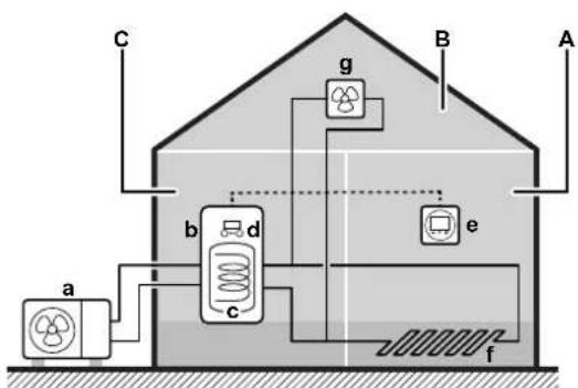
3.1 Components in a typical system layout
flowchart
graph TD
    A["Component a"] --> B["Valve 1"]
    B --> C["Valve 2"]
    C --> D["Valve 3"]
    D --> E["Valve 4"]
    E --> F["Valve 5"]
    F --> G["Valve 6"]
    G --> H["Valve 7"]
    H --> I["Valve 8"]
    I --> J["Valve 9"]
    J --> K["Valve 10"]
    K --> L["Valve 11"]
    L --> M["Valve 12"]
    M --> N["Valve 13"]
    N --> O["Valve 14"]
    O --> P["Valve 15"]
    P --> Q["Valve 16"]
    Q --> R["Valve 17"]
    R --> S["Valve 18"]
    S --> T["Valve 19"]
    T --> U["Valve 20"]
    U --> V["Valve 21"]
    V --> W["Valve 22"]
    W --> X["Valve 23"]
    X --> Y["Valve 24"]
    Y --> Z["Valve 25"]
    Z --> AA["Valve 26"]
    AA --> AB["Valve 27"]
    AB --> AC["Valve 28"]
    AC --> AD["Valve 29"]
    AD --> AE["Valve 30"]
    AE --> AF["Valve 31"]
    AF --> AG["Valve 32"]
    AG --> AH["Valve 33"]
    AH --> AI["Valve 34"]
    AI --> AJ["Valve 35"]
    AJ --> AK["Valve 36"]
    AK --> AL["Valve 37"]
    AL --> AM["Valve 38"]
    AM --> AN["Valve 39"]
    AN --> AO["Valve 40"]
    AO --> AP["Valve 41"]
    AP --> AQ["Valve 42"]
    AQ --> AR["Valve 43"]
    AR --> AS["Valve 44"]
    AS --> AT["Valve 45"]
    AT --> AU["Valve 46"]
    AU --> AV["Valve 47"]
    AV --> AW["Valve 48"]
    AW --> AX["Valve 49"]
    AX --> AY["Valve 50"]
A Main zone. Example: Living room.
B Additional zone. Example: Bedroom.
C Technical room. Example: Garage.
a Outdoor unit heat pump
b Indoor unit heat pump
c Energy storage tank
d User interface of the indoor unit
e Dedicated Human Comfort Interface (BRC1HHDA used as room thermostat)
f Underfloor heating
g Radiators, heat pump convectors, or fan coil units
4 Quick guide
4.1 User permission level
The amount of information you can read out and edit in the menu structure depends on your user permission level:
- User: Standard mode
- Advanced user: You can read out and edit more information
To change the user permission level
| 1 Go to [B]: User profile. | ### | |
| 2 Enter the applicable pin code for the user permission level. — | ||
| ·Browse through the list of digits and change the selected digit. | ○···· | |
| ·Move the cursor from left to right. | ### | |
| ·Confirm the pin code and proceed. | ### | |
User pin code
The User pin code is 0000.

text_image
User 0000Advanced user pin code
The Advanced user pin code is 1234. Additional menu items for the user are now visible.

text_image
Advanced user 12344.2 Space heating/cooling
To turn space heating/cooling operation ON or OFF

NOTICE
Room frost protection. Even if you turn OFF space heating/cooling operation ([C.2]: Operation > Space heating/cooling), room frost protection operation – if enabled— can still activate. However, for leaving water temperature control and external room thermostat control, the protection is NOT guaranteed.

NOTICE
Water pipe freeze prevention. Even if you turn OFF space heating/cooling operation ([C.2]: Operation > Space heating/cooling), water pipe freeze prevention – if enabled – will remain active.
| 1 | Go to [C.2]: Operation > Space heating/cooling.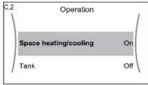 | [IMAGE] |
| 2 | Set operation to On or Off. | ○···· |
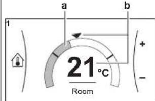
To change the desired room temperature
During room temperature control, you can use the room temperature setpoint screen to read out and adjust the desired room temperature.
1 Go to [1]: Room.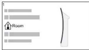 | [IMAGE] |
2 Adjust the desired room temperature.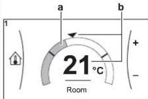 a Actual room temperatureb Desired room temperature a Actual room temperatureb Desired room temperature | ○⋯○: |
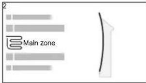
To change the desired leaving water temperature
You can use the leaving water temperature setpoint screen to read out and adjust the desired leaving water temperature.
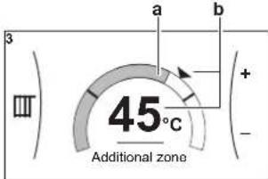
| 1 | Go to [2]: Main zone or [3]: Additional zone. | ### |
 | ||
 |
| 2 Adjust the desired leaving water temperature. | ○··· |
| a Actual leaving water temperature b Desired leaving water temperature |
To change the weather-dependent curve for the space heating/cooling zones
1 Go to the applicable zone:
| Zone Go to ... | |
| Main zone – Heating | [2.5] Main zone > Heating WD curve |
| Main zone – Cooling | [2.6] Main zone > Cooling WD curve |
| Additional zone – Heating | [3.5] Additional zone > Heating WD curve |
| Additional zone – Cooling | [3.6] Additional zone > Cooling WD curve |
2 Change the weather-dependent curve.
There are 2 types of WD curves: slope-offset curve (default), and 2-points curve. If needed, you can change the type in [2.E] Main zone >WD curve type. The way to adjust the curve depends on the type.
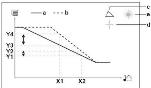
Slope-offset curve
Slope. When slope is changed, the new preferred temperature at X1 is unequally higher than the preferred temperature at X2.

Offset. When offset is changed, the new preferred temperature at X1 is equally higher as the preferred temperature at X2.
X1, X2 Outdoor ambient temperature
Y1\~Y4 Desired leaving water temperature
a WD curve before changes
b WD curve after changes
c Slope
d Offset
| Possible actions on this screen | |
| ○···○ | Select slope or offset. |
| ○···○ | Increase or decrease the slope/offset. |
| ○···○m | When slope is selected: set slope and go to offset.When offset is selected: set offset. |
| ○m···○ | Confirm changes and return to the submenu. |
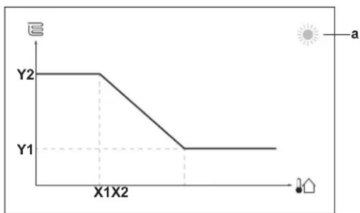
2-points curve
line
| Point | Value | |---|---| | Y1 | 0 | | Y2 | 0 | | X1X2 | 0 |X1, X2 Outdoor ambient temperature
Y1, Y2 Desired leaving water temperature
| Possible actions on this screen | |
| ○⋯○ | Go through the temperatures. |
| ○⋯○ | Change the temperature. |
| ○⋯○m | Go to the next temperature. |
| ○m⋯○ | Confirm changes and proceed. |
More information
For more information, see also:
- "5.4 Turning operation ON or OFF" [▶ 24]
- "5.6 Space heating/cooling control" [▶ 26]
- "5.8 Preset values and schedules" [▶ 34]
- "5.9 Weather-dependent curve" [▶ 43]
4.3 Domestic hot water
To turn tank heating operation ON or OFF

NOTICE
To ensure safe operation of the system, do NOT turn off DHW when space heating is required.

NOTICE
Disinfection mode. Even if you turn OFF tank heating operation ([C.3]: Operation > Tank), disinfection mode will remain active. However, if you turn it OFF while disinfection is running, an AH error occurs.
1 Go to [C.3]: Operation > Tank.
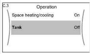
text_image
C.3 Operation Space heating/cooling On Tank Off
| 2 Set operation to On or Off. | ○···●: |
To change the tank temperature setpoint
In Reheat only mode, you can use the tank temperature setpoint screen to read out and adjust the storage tank temperature. The resulting domestic hot water temperature depends on this setpoint as well as the actual storage tank temperature.
1 Go to [5]: Tank. | 10...○ |
2 Adjust the domestic hot water temperature.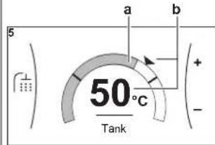 a Actual domestic hot water temperatureb Desired domestic hot water temperature a Actual domestic hot water temperatureb Desired domestic hot water temperature | ○...○: |
In other modes, you can only view the setpoint screen but not modify it.
More information
For more information, see also:
- "5.4 Turning operation ON or OFF" [▶ 24]
- "5.7 Domestic hot water control" [▶ 31]
- "5.8 Preset values and schedules" [▶ 34]
5 Operation

INFORMATION
Cooling is only applicable in case of reversible models.
5.1 User interface: Overview
The user interface has the following components:

text_image
Technical diagram of a device casing with labeled parts a, b, and ca Status indicator
b LCD screen
c Dials and buttons
Status indicator
The LEDs of the status indicator light up or blink to show the operating mode of the unit.
| LED Mode Description | |
| Blinking blue Standby The unit is not in operation. | |
| Continuous blue Operation The unit is in operation. | |
| Blinking red Malfunction A malfunction occurred. See "8.1 To display the help text in case of a malfunction" [▶ 56] for more information. | |
Slot for WLAN cartridge
With the WLAN cartridge, the installer can connect the system to the internet. As user you can then control the system via the Daikin Residential Controller app.
Note: This slot cannot be used for SD cards.
USB connector
With a USB memory stick, the installer can:
- Update the software. This requires a correct config file on the USB memory stick.
- Import the settings generated by E-Configurator (Heating Solutions Navigator) from the USB memory stick to the user interface (MMI). This requires a correct config file on the USB memory stick.
- Export the current settings (i.e. field settings, MMI EEPROM settings, schedule timers) from the user interface (MMI) to the USB memory stick.
LCD screen
The LCD screen has a sleeping function. After 15 min of non-interaction with the user interface, the screen darkens. Pressing any button or rotating any dial awakens the display.
Dials and buttons
You use the dials and buttons:
- To navigate through the screens, menus and settings of the LCD screen
- To set values

text_image
abcde| Item Description | ||
| a | Left dial The LCD | shows an arc on the left side of the display when you can use the left dial.▪Turn, then press the left dial. Navigate through the menu structure.▪Turnthe left dial. Choose a menu item.:Press the left dial. Confirm your choice or go to a submenu. |
| b | Back button: Press to go back 1 step in the menu structure. | |
| c | Home button: Press to go back to the home screen. | |
| d | Help button: Press to show a help text related to the current page (if available). | |
| e | Right dial The LCD shows an arc on the right side of the display when you can use the right dial.▪:Turn, then press the right dial. Change a value or setting, shown at the right side of the screen.▪:Turnthe right dial. Navigate through the possible values and settings.▪:Press the right dial. Confirm your choice and go to the next menu item. | |
5.2 Menu structure: Overview user settings

flowchart
graph TD
    A["[1"] Room] --> B["Schedule"]
    B --> C["Heating schedule"]
    C --> D["(*) Cooling schedule"]
    D --> E["Antifrost"]
    E --> F["Setpoint range"]
    F --> G["Room sensor offset"]
    G --> H["Room comfort setpoint"]

    I["[2"] Main zone] --> J["Schedule"]
    J --> K["Heating schedule"]
    K --> L["(*) Cooling schedule"]
    L --> M["Setpoint mode"]
    M --> N["Heating WD curve"]
    N --> O["(*) Cooling WD curve"]
    O --> P["WD curve type"]

    Q["[3"] Additional zone] --> R["Schedule"]
    R --> S["Heating schedule"]
    S --> T["(*) Cooling schedule"]
    T --> U["Setpoint mode"]
    U --> V["Heating WD curve"]
    V --> W["(*) Cooling WD curve"]
    W --> X["WD curve type"]

    Y["[4"] Space heating/cooling] --> Z["Operation mode"]
    Z --> AA["(*) Operation mode schedule"]

    AB["[5"] Tank] --> AC["Powerful operation"]
    AC --> AD["Schedule"]

    AE["[7"] User settings] --> AF["Language"]
    AF --> AG["Time/date"]
    AG --> AH["Holiday"]
    AH --> AI["Quiet"]
    AI --> AJ["Electricity price"]
    AJ --> AK["Gas price"]

    AL["[8"] Information] --> AM["Energy data"]
    AM --> AN["Malfunction history"]
    AN --> AO["Dealer information"]
    AO --> AP["Sensors"]
    AP --> AQ["Actuators"]
    AQ --> AR["Operation modes"]
    AR --> AS["About"]
    AS --> AT["Connection status"]
    AT --> AU["Running hours"]
    AU --> AV["Piping diagram"]

    AW["[B"] User profile] --> AX["C"] Operation
    AY["[1.4"] Antifrost] --> AZ["Activation"]
    AZ --> BA["Room setpoint"]

    BB["[1.5"] Setpoint range] --> BC["Heating minimum"]
    BC --> BD["Heating maximum"]
    BD --> BE["(*) Cooling minimum"]
    BE --> BF["(*) Cooling maximum"]

    BG["[1.9"] Room comfort setpoint] --> BH["Heating comfort setpoint"]
    BH --> BI["(*) Cooling comfort setpoint"]

    BJ["[7.2"] Time/date] --> BK["Hours"]
    BK --> BL["Minutes"]
    BL --> BM["Year"]
    BM --> BN["Month"]
    BN --> BO["Day"]
    BO --> BP["Daylight savings time"]
    BP --> BQ["Format"]

    BR["[7.3"] Holiday] --> BS["Activation"]
    BS --> BT["From"]
    BT --> BU["Till"]

    BV["[7.4"] Quiet] --> BW["(**) Activation"]
    BW --> BX["Schedule"]
    BX --> BY["(**) Level"]

    BZ["[7.5"] Electricity price] --> CA["High"]
    CA --> CB["Medium"]
    CB --> CC["Low"]
    CC --> CD["Schedule"]

    CE["[8.1"] Energy data] --> CF["Electricity input"]
    CF --> CG["Produced heat"]
    CG --> CH["Energy flow"]

    CI["(**) [D"] Wireless gateway] --> CJ["Mode"]
    CJ --> CJ1["Reboot"]
    CJ --> CJ2["WPS"]
    CJ --> CJ3["Remove from cloud"]
    CJ --> CJ4["Home network connection"]
    CJ --> CJ5["Cloud connection"]
Setpoint screen
(*) Only applicable for reversible models, or heating only models + conversion kit
(**) Only accessible by installer
(***) Only applicable when WLAN is installed

INFORMATION
Depending on the selected installer settings and unit type, settings will be visible/ invisible.
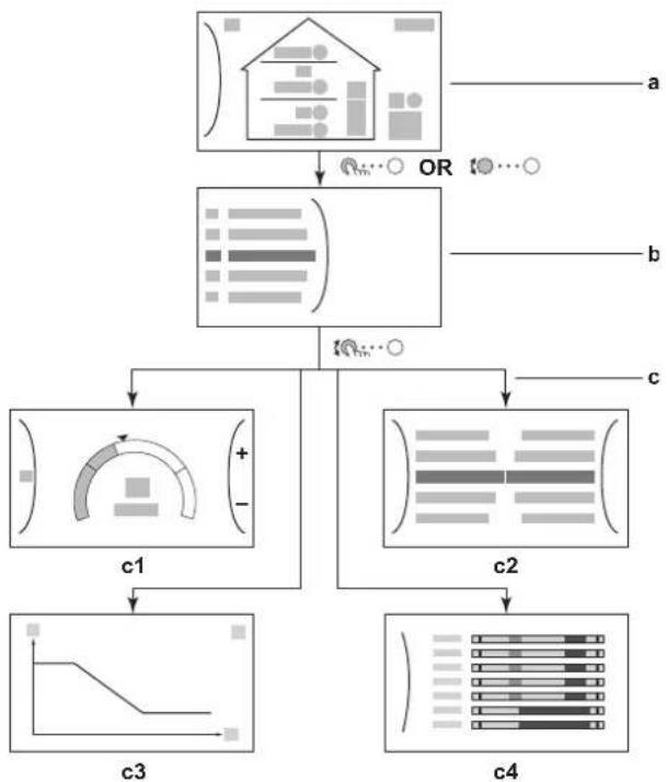
5.3 Possible screens: Overview
The most common screens are as follows:
flowchart
graph TD
    A["Input Data"] --> B{OR}
    B --> C["Output"]
    subgraph Module1
        D["Input Data"] --> E["Component 1"]
        E --> F["Output"]
    end
    subgraph Module2
        G["Component 2"]
        H["Output"]
    end
    subgraph Module3
        I["Component 3"]
        J["Output"]
    end
    subgraph Module4
        K["Component 4"]
        L["Output"]
    end
a Home screen
b Main menu screen
c Lower level screens:
c1: Setpoint screen
c2: Detailed screen with values
c3: Screen with weather-dependent curve
c4: Screen with schedule
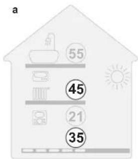
5.3.1 Home screen
Press the 🔊 button to go back to the home screen. You see an overview of the unit configuration and the room and setpoint temperatures. Only symbols applicable for your configuration are visible on the home screen.

text_image
a2a1e3 b c 26 Feb 2019 22:19 d 55 45 21 35 1.6 bar i2 i3 i4 h2i1 h1 j k1 k2 k3 e2 e1 f g1 g2 g3| Possible actions on this screen | |
| ○⋯○ | Go through the list of the main menu. |
| ○⋯○ | Go to the main menu screen. |
| ? | Enable/disable breadcrumbs. |
| Item Description | |||
| a Domestic hot water | |||
a1  hot water hot water | |||
a2  | Measured tank temperature(a) | ||
| b Disinfection / Powerful | |||
 | Disinfection mode active | ||
 | Powerful operation mode active | ||
| c Emergency | |||
| [80T4] | Heat pump failure and system operates in Emergency mode or heat pump is forced off. | ||
d Curren  | |||
| e Smart energy | |||
e1  | ergy is available via solar panels or smart grid. | ||
| e2 [ZW60] | ergy is currently being used for space heating. | ||
e3  | ergy is currently being used for domestic hot water. | ||
| f Space operation mode | |||
| [S242] | Cooling | ||
| [74D2] | Heating | ||
| g Outdoor / quiet mode | |||
| g1 [SBAT] | Measured outdoor temperature(a) | ||
g2  | mode active | ||
| g3 [WYAZ] | unit | ||
| h Indoor unit / domestic hot water tank | |||
h1  | inding indoor unit with integrated tank | ||
| [W673] | |||
| [30AD] | Wall-mounted indoor unit | ||
 | Wall-mounted indoor unit with separated tank | ||
h2  | pressure | ||
| i Main zone | |||
(e) If the corresponding operation (for example: space heating) is not active, the circle is greyed out.
5.3.2 Main menu screen
Starting from the home screen, press ( ) or turn ( ) the left dial to open the main menu screen. From the main menu, you can access the different setpoint screens and submenus.
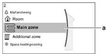
text_image
2 Mafunctioning Room Main zone Additional zone Spesa hastengicooning aa Selected submenu
| Possible actions on this screen | |
| ○⋯○ | Go through the list. |
| ○⋯○ | Enter the submenu. |
| ? | Enable/disable breadcrumbs. |
| Submenu Description | ||
| [0] | orMalfunctioning | Restriction: Only displayed if a malfunction occurs.See "8.1 To display the help text in case of a malfunction" [▶ 56] for more information. |
| [1] | Room | Restriction: Only displayed if a dedicated Human Comfort Interface (BRC1HHDA used as room thermostat) is controlling the indoor unit.Set the room temperature. |
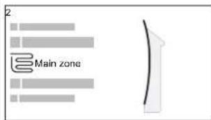
| [2] | Main zone | Shows the applicable symbol for your main zone emitter type.Set the leaving water temperature for the main zone. |
| [3] | Additional zone Restriction | Only displayed if there are two leaving water temperature zones. Shows the applicable symbol for your additional zone emitter type.Set the leaving water temperature for the additional zone (if present). |
| [4] | Space heating/ cooling | Shows the applicable symbol of your unit.Put the unit in heating mode or cooling mode.You cannot change the mode on heating only models. |
| [5] | Tank | Set the storage tank temperature. |
| [7] | User settings | Gives access to user settings such as holiday mode and quiet mode. |
| [8] | Information | Displays data and information about the indoor unit. |
| [9] | Installer settings | Restriction: Only for the installer.Gives access to advanced settings. |
| Submenu Description | |||
| [WSA8] | [SS36] | [4680] | Restriction: Only for the installer.Perform tests and maintenance. |
| [1482] | [AGTT] |  | Change the active user profile. |
 |  |  | Turn heating/cooling functionality and domestic hot water preparation on or off. |
 | [GYH5] |  | |
5.3.3 Setpoint screen
The setpoint screen is displayed for screens describing system components that need a setpoint value.
Examples
[1] Room temperature screen
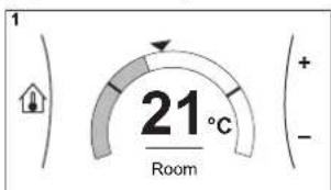
text_image
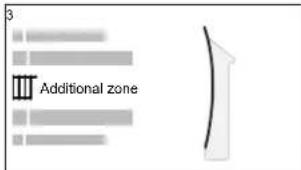
1 21° Room + - -[3] Additional zone screen
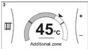
text_image
3 III 45°C Additional zone + - -[2] Main zone screen

text_image
2 35°c Main zone + - -[5] Tank temperature screen

text_image
5 50°C TankExplanation
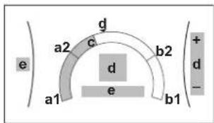
| Possible actions on this screen | |
| ○⋯○ | Go through the list of the submenu. |
| ○⋯○ | Go to the submenu. |
| ○⋯○ | Adjust and automatically apply the desired temperature. |
| Item Description | ||
| Minimum temperature limit a1 Fixed by the unit | ||
| Maximum temperature limit b1 Fixed by the unit | ||
| Current temperature c Measured by the unit | e unit | |
| Desired temperature d Turn the right dial to increase/decrease. | dial to increase/decrease. | |
| Submenu e Turn or press the left dial to go to | go to | the submenu. |
5.3.4 Detailed screen with values

text_image
a c ba Settings
b Values
c Selected setting and value
Example:

text_image
7.2.1 Time/date Hours 11 Minutes 30 a c b| Possible actions on this screen | |
| ○⋯○ | Go through the list of settings. |
| ○⋯○ | Change the value. |
| ○⋯○m | Go to the next setting. |
| ○⋯○ | Confirm changes and proceed. |
5.4 Turning operation ON or OFF
5.4.1 Visual indication
Certain functionalities of the unit can be enabled or disabled separately. If a functionality is disabled, the corresponding temperature icon in the home screen will be greyed out.
Space heating/cooling operation
text_image
a 55 45 21 35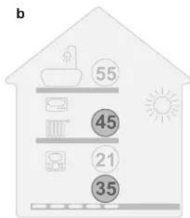
text_image
b 55 45 21 35a Space heating/cooling operation ON
b Space heating/cooling operation OFF
Tank heating operation

text_image
c 55 45 21 35c Tank heating operation ON d Tank heating operation OFF

text_image
d 55 45 21 355.4.2 To turn ON or OFF
Space heating/cooling operation

NOTICE
Room frost protection. Even if you turn OFF space heating/cooling operation ([C.2]: Operation > Space heating/cooling), room frost protection operation –if enabled– can still activate. However, for leaving water temperature control and external room thermostat control, the protection is NOT guaranteed.

NOTICE
Water pipe freeze prevention. Even if you turn OFF space heating/cooling operation ([C.2]: Operation > Space heating/cooling), water pipe freeze prevention – if enabled— will remain active.
1 Go to [C.2]: Operation > Space heating/cooling.

flowchart
graph LR
    A["Operation"] --> B["Space heating/cooling"]
    B --> C["Tank"]
    B --> D["Off"]
    style B fill:#cccccc,stroke:#333,stroke-width:2px
2 Set operation to On or Off.
Im ·s O
○…
Tank heating operation

NOTICE
To ensure safe operation of the system, do NOT turn off DHW when space heating is required.

NOTICE
Disinfection mode. Even if you turn OFF tank heating operation ([C.3]: Operation > Tank), disinfection mode will remain active. However, if you turn it OFF while disinfection is running, an AH error occurs.
1 Go to [C.3]: Operation >Tank.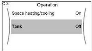 | [IMAGE] | |
| 2 Set operation to On or Off. | ○...○ | |
5.5 Reading out information
To read out information
| 1 Go to [8]: Information. | ### |
Possible read-out information
| In menu... You can read out... | |
| [8.1] Energy data Produced energy, consumed electricity,and consumed gas, energy flow diagram | |
| [8.2] Malfunction history Malfunction history | |
| [8.3] Dealer information Contact/helpdesk number | |
| [8.4] Sensors Room, tank or domestic hot water,outside, and leaving water temperature(if applicable) | |
| [8.5] Actuators Status/mode of each actuatorExample:Domestic hot water pumpON/OFF | |
| [8.6] Operation modes Current operation modeExample:Defrost/oil return mode | |
| [8.7] About Version information about the system | |
| [8.8] Connection status Information about the connectionstatus of the unit, the room thermostatand the LAN adapter. | |
| [8.9] Running hours Running hours of specific systemcomponents | |
| [8.B] Piping diagram Real-time sensor and actuatorinformation of the main systemcomponents |
5.6 Space heating/cooling control
5.6.1 About space heating/cooling control
Controlling space heating/cooling typically consists of the following stages:
1 Setting the space operation mode
2 Controlling the temperature
Depending on the system layout and installer configuration, you use a different temperature control:
■ Room thermostat control
■ Leaving water temperature control
■ External room thermostat control
5.6.2 Setting the space operation mode
About space operation modes
Your unit can be a heating or a heating/cooling model:
- If your unit is a heating model, it can heat up a space.
- If your unit is a heating/cooling model, it can both heat up and cool down a space. You have to tell the system which operation mode to use.
To determine if a heating/cooling heat pump model is installed
| 1 Go to [4]: Space heating/cooling. | ###...○ | |
| 2 Check if [4.1] Operation mode is listed and editable. If so, a heating/cooling heat pump model is installed. | ###...○ | |
To tell the system which space operation to use, you can:
| You can... Location | |
| Check which space operation mode is currently used. | Home screen |
| Set the space operation mode permanently. Main menu | |
| Restrict automatic changeover according to a monthly schedule. |
To check which space operation mode is currently used
The space operation mode is displayed on the home screen:
- When the unit is in heating mode, the icon is shown.
- When the unit is in cooling mode, the icon is shown.
The status indicator shows if the unit is currently in operation:
- When the unit is not in operation, the status indicator will show a blue pulsation with an interval of approximately 5 seconds.
- While the unit is in operation, the status indicator will light up blue constantly.
To set the space operation mode
| 1 | Go to [4.1]: Space heating/cooling >Operation mode | ### |
| 2 | Select one of the following options:Heating: Only heating modeCooling: Only cooling modeAutomatic: The operation mode changes automatically between heating and cooling based on the outdoor temperature. Restricted per month according to the Operation mode schedule [4.2]. | ### |
To restrict automatic changeover according to a schedule
Conditions: You set the space operation mode to Automatic.
| 1 | Go to [4.2]: Space heating/cooling >Operation mode schedule. | |
| 2 | Select a month. | |
| 3 | For each month, select an option:Reversible: Not restrictedHeating only: RestrictedCooling only: Restricted | |
| 4 | Confirm the changes. |
Example: Changeover restrictions
| When Restriction | |
| During cold season.Example:October, November, December, January, February and March. | Heating only |
| During warm season.Example:June, July and August. | Cooling only |
| In-between.Example:April, May and September. | Reversible |
5.6.3 Determining which temperature control you are using
To determine which temperature control you are using (method 1)
Check the installer settings table filled in by the installer.
To determine which temperature control you are using (method 2)
You can see on the home screen which temperature control you are using.

text_image
18 Feb 2018 22:19 a2 b a1 55 45 21 35 1.6 bar 6a1 Heat emitter of the main zone (in this example Underfloor heating)
a2 Heat emitter of the additional zone (in this example Radiator). If no icon is displayed, there is no additional zone.
b Room thermostat type of the main zone:
| If b=... Then the temperature control is... | ||
| Room thermostat control | External room thermostat control | |
| External room thermostat control | ||
| No icon Leaving water temperature control | Leaving water temperature control | |
5.6.4 To change the desired room temperature
During room temperature control, you can use the room temperature setpoint screen to read out and adjust the desired room temperature.
| 1 Go to [1]: Room. | ### | |
 | ||
| 2 Adjust the desired room temperature. | ○··· | |
 | ||
| a Actual room temperatureb Desired room temperature | ||
If scheduling is on after changing the desired room temperature
- The temperature will stay the same as long as there is no scheduled action.
- The desired room temperature will return to its scheduled value whenever a scheduled action occurs.
You can avoid scheduled behaviour by (temporarily) turning off scheduling.
To turn off room temperature scheduling
| 1 Go to [1.1]: Room > Schedule. | ###...○ | |
| 2 Select No. | ###...○ | |
5.6.5 To change the desired leaving water temperature

INFORMATION
The leaving water is the water that is sent to the heat emitters. The desired leaving water temperature is set by your installer in accordance with the heat emitter type. Only adjust the leaving water temperature settings in case of problems.
You can use the leaving water temperature setpoint screen to read out and adjust the desired leaving water temperature.
| 1 | Go to [2]: Main zone or [3]: Additional zone. | ### |
 | ||
 | ||
| 2 | Adjust the desired leaving water temperature. | ○··· |
 | ||
 | ||
| a Actual leaving water temperatureb Desired leaving water temperature |
If scheduling is on after changing the desired leaving water temperature
- The temperature will stay the same as long as there is no scheduled action. - The desired leaving water temperature will return to its scheduled value whenever a scheduled action occurs.
You can avoid scheduled behaviour by (temporarily) turning off scheduling.
To turn off leaving water temperature scheduling
| 1 Go to one of the following:▪ [2.1]: Main zone > Schedule▪ [3.1]: Additional zone > Schedule | IR...○ |
| 2 Select No. | IR...○ |
To enable weather-dependent operation for the leaving water temperature
See "5.9.4 Using weather-dependent curves" [▶ 46].
5.7 Domestic hot water control
5.7.1 About domestic hot water control
Depending on the DHW tank mode (installer setting), you use a different domestic hot water control:
- Reheat only
- Scheduled reheat

INFORMATION
In case of error code AH and no interruption of the disinfection function occurred due to domestic hot water tapping, following actions are recommended:
- It is recommended to program the start-up of the disinfection function at least 4 hours later than the last expected large hot water tapping. This start-up can be set by installer settings (disinfection function).
When weather-dependent operation is used for the tank, the tank temperature is determined automatically by the outdoor temperature. For more information, see "5.9 Weather-dependent curve" [▶ 43].
To determine which domestic hot water mode you are using (method 1)
Check the installer settings table filled in by the installer.
To determine which domestic hot water mode you are using (method 2)
| 1 Go to [5]: Tank. | t_min ·s O | |
| 2 Check which items are displayed:[5.1] [5.5] [5.1] [5.5] [5.1] [5.5] [5.1] [5.5] [5.1] [5.5] [5.1] [5.5] [5.1] [5.5] [5.1] [5.5] [5.1] [5.5] [5.1] [5.5] [5.1] [5.5] | [5.1] [5.5] [5.1] [5.5] [5.1] [5.5] [5.1] [5.5] [5.1] [5.5] [5.1] [5.5] [5.1] [5.5] [5.1] [5.5] [5.1] [5.5] [5.1] [5.5] | |
| If... is displayed Then the DHW tank mode =... | |
| Only [5.1] Powerful operation | Reheat only |
| [5.1] Powerful operation and [5.5] Schedule are displayed | Scheduled reheat |
5.7.2 Reheat mode
In reheat mode the storage tank continuously heats up to the temperature shown on the home screen (example: 50^ C) when the temperature drops below a certain value.

line
| Time | Tt | | ------------- | ---- | | 00:00:07:00 | 50°C | | 14:00:21:00 | 50°C |T_t Storage tank temperature t Time

INFORMATION
Risk of space heating capacity shortage: In case of frequent tank operation, frequent and long space heating/cooling interruption will happen when selecting the following:
Tank > Heat up mode > Reheat only.
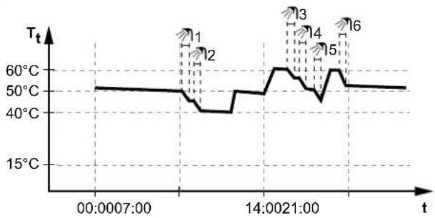
5.7.3 Scheduled reheat mode
In scheduled reheat mode the storage tank set temperature varies according to the schedule. When the tank temperature drops below the set temperature minus the heat pump ON hysteresis temperature [6-00], the tank heats up to the reheat temperature.
Example:
line
| t | Tt | | -------------- | ---- | | 00:00:07:00 | 50°C | | 14:00:21:00 | 60°C |T_t Storage tank temperature t Time
- At 14:00 the DHW schedule is programmed to heat up the tank to 60^ .
- At 21:00 the DHW schedule is programmed to heat up the tank to 50^ . This value is valid until 14:00 the next day.
- With the higher set temperature, in the afternoon and evening more hot water is available.
- During the morning, you consume hot water and the storage tank temperature decreases.
- When the tank temperature drops below a preset value (=set temperature – hysteresis value; example 40°C), the tank is heated up to 50°C.
- During the afternoon and evening, you consume hot water again and the DHW tank temperature decreases again.
- When the tank temperature drops below a preset value (=set temperature – hysteresis value; example 50°C), the tank is heated up to 60°C.
5.7.4 To change the domestic hot water temperature
In Reheat only mode, you can use the tank temperature setpoint screen to read out and adjust the domestic hot water temperature.
| 1 Go to [5]: Tank. | [IMAGE] |
| 2 Adjust the domestic hot water temperature. |  a Actual domestic hot water temperatureb Desired domestic hot water temperature a Actual domestic hot water temperatureb Desired domestic hot water temperature |
In other modes, you can only view the setpoint screen but not modify it.
When weather-dependent operation is used for the tank, the tank temperature is determined automatically by the outdoor temperature. For more information, see "5.9 Weather-dependent curve" [43].
5.7.5 Using DHW powerful operation
About powerful operation
Powerful operation allows the domestic hot water to be heated by the backup heater or booster heater. Use this mode on days when there is more hot water usage than usual.
To check if powerful operation is active
If is displayed on the home screen, powerful operation is active.
Activate or deactivate Powerful operation as follows:
| 1 Go to [5.1]: Tank > Powerful operation | 10...○ |
| 2 Turn powerful operation Off or On. | 10...○ |
Usage example: You immediately need more hot water
You are in the following situation:
- You already consumed most of your domestic hot water.
- You cannot wait for the next scheduled action to heat up the domestic hot water tank.
Then you can activate powerful operation. The domestic hot water tank will start heating up the water to the Comfort temperature.

INFORMATION
When powerful operation is active, the risk of space heating/cooling and capacity shortage comfort problems is significant. In case of frequent domestic hot water operation, frequent and long space heating/cooling interruptions will happen.
5.8 Preset values and schedules
5.8.1 Using preset values
About preset values
For some settings in the system, you can define preset values. You only need to set these values one time, then reuse the values in other screens such as the scheduling screen. If you later want to change the value, you only have to do it in one place.
Possible preset values
You can set the following user-defined preset values:
| Preset value Where used | ||
| Electricity prices under [7.5] User settings > Electricity priceRestriction: Only applicable if Bivalent is enabled by the installer. | [7.5.1] High You can | n use these preset values in [7.5.4] Schedule (weekly schedule screen for the energy prices).See "5.8.4 Setting the energy prices" [ ▶ 41]. |
| [7.5.2] Medium | ||
| [7.5.3] Low | ||
Additional to the user-defined preset values, the system also contains some system-defined preset values that you can use when programming schedules.
Example: In [7.4.2] User settings > Quiet > Schedule (weekly schedule for when the unit has to use which quiet mode level), you can use the following system-defined preset values: Quiet/More quiet/Most quiet.
5.8.2 Using and programming schedules
About schedules
Depending on your system layout and installer configuration, schedules for multiple controls may be available.
| You can... See... | |
| Set if a specific control needs to act according to a schedule. | "Activation screen" in "Possible schedules" [ ▶ 35] |
| Select which schedule you currently want to use for a specific control. The system contains some predefined schedules. You can: | |
| You can... See... | ||
| Consult which schedule is currently selected. | "Schedule/Control" in "Possible schedules" [ ▶ 35] | |
| Select another schedule if needed. "To select which schedule you currently want to use" [ ▶ 35] | ||
| Program your own schedules if the predefined schedules are not satisfactory. The actions you can program are control specific. | • "Possible actions" in "Possible schedules" [ ▶ 35]• "5.8.3 Schedule screen: Example" [ ▶ 37] | |
To select which schedule you currently want to use
| 1 Go to the schedule for the specific control.See "Schedule/Control" in "Possible schedules" [▶ 35].Example: For the schedule for the desired room temperature in heating mode, go to [1.2] Room > Heating schedule. | |
2 Select the name of the current schedule. | ###...○ |
3 Select Select.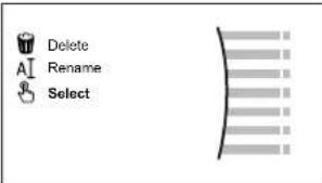 | ###...○ |
| 4 Select the schedule that you currently want to use. | ###...○ |
Possible schedules
The table contains the following information:
- Schedule/Control: This column shows you where you can consult the currently selected schedule for the specific control. If needed, you can:
- Select another schedule. See "To select which schedule you currently want to use" [▶ 35].
- Program your own schedule. See "5.8.3 Schedule screen: Example" [▶ 37].
- Predefined schedules: Number of available predefined schedules in the system for the specific control. If needed, you can program your own schedule.
- Activation screen: For most controls, a schedule is only effective if it activated in its corresponding activation screen. This entry shows you where to activate it.
- Possible actions: Actions you can use when programming a schedule. For most schedules, you can program up to 6 actions per day.
| Schedule/Control Description | |
| [1.2] Room > Heating scheduleSchedule for the desired room temperature in heating mode. | Predefined schedules: 3Activation screen: [1.1] SchedulePossible actions: Temperatures within range. |
| [1.3] Room > Cooling scheduleSchedule for the desired room temperature in cooling mode. | Predefined schedules: 1Activation screen: [1.1] SchedulePossible actions: Temperatures within range. |
| [2.2] Main zone > Heating scheduleSchedule for the desired leaving water temperature for the main zone in heating mode. | Predefined schedules: 3Activation screen: [2.1] SchedulePossible actions:In case of weather-dependent: Shift temperatures within range.Otherwise: Temperatures within range |
| [2.3] Main zone >Cooling scheduleSchedule for the desired leaving water temperature for the main zone in cooling mode. | Predefined schedules: 1Activation screen: [2.1] SchedulePossible actions:In case of weather-dependent: Shift temperatures within range.Otherwise: Temperatures within range |
| [3.2] Additional zone > Heating scheduleSchedule for when the system is allowed to heat up the additional zone in heating mode. | Predefined schedules: 1Activation screen: [3.1] SchedulePossible actions:Off: When the system is NOT allowed to heat up the additional zone.On: When the system is allowed to heat up the additional zone. |
| [3.3] Additional zone > Cooling scheduleSchedule for when the system is allowed to cool down the additional zone in cooling mode. | Predefined schedules: 1Activation screen: [3.1] SchedulePossible actions:Off: When the system is NOT allowed to cool down the additional zone.On: When the system is allowed to cool down the additional zone. |
| [4.2] Space heating/ cooling >Operation mode scheduleSchedule (per month) for when to operate the unit in heating mode and when in cooling mode. | See "To set the space operation mode" [▶ 27]. |
| Schedule/Control Description | |
| [5.5] Tank > ScheduleSchedule for the domestic hot water tank temperature for your normal domestic hot water needs. | Predefined schedules: 1Activation screen: Not applicable. This schedule is automatically activated if the DHW mode is the following:Scheduled reheat |
| [7.4.2] User settings >Quiet > ScheduleSchedule for when the unit has to use which quiet mode level. | Predefined schedules: 1Activation screen: [7.4.1] Activation (only available to installers).Possible actions: You can use the following system-defined preset values:QuietMore quietMost quietSee "About quiet mode" [▶ 49]. |
| [7.5.4] User settings >Electricity price >ScheduleSchedule for when a certain electricity tariff is valid. | Predefined schedules: 1Activation screen: Not applicablePossible actions: You can use the following system-defined preset values:HighMediumLowSee "5.8.4 Setting the energy prices" [▶ 41]. |
5.8.3 Schedule screen: Example
This example shows how to set a room temperature schedule in heating mode for the main zone.

INFORMATION
The procedures to program other schedules are similar.
To program the schedule: overview
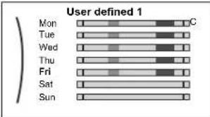
Example: You want to program the following schedule:
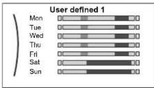
text_image
User defined 1 Mon Tue Wed Thu Fri Sat SunPrerequisite: The room temperature schedule is only available if room thermostat control is active. If leaving water temperature control is active, you can program the main zone schedule instead.
1 Go to the schedule.
2 (optional) Clear the content of the whole week schedule or the content of a selected day schedule.
3 Program the schedule for Monday.
4 Copy the schedule to the other weekdays.
5 Program the schedule for Saturday and copy it to Sunday.
6 Give the schedule a name.
To go to the schedule
| 1 | Go to [1.1]: Room > Schedule. | ###...○ |
| 2 | Set scheduling to Yes. | ###...○ |
| 3 | Go to [1.2]: Room > Heating schedule. | ###...○ |
To clear the content of the week schedule
| 1 Select the name of the current schedule. | 10...○ | |
| 2 Select Delete. | 10...○ | |
| 3 Select OK to confirm. | 10...○ | |
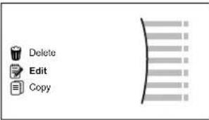
To clear the content of a day schedule
| 1 Select the day of which you want to clear the content. For example FridayUser defined 1Mon Tue Wed Thu Fri Sat Sun | QQ...○ |
| 2 Select Delete.DeleteEditCopy | QQ...○ |
| 3 Select OK to confirm. | QQ...○ |
To program the schedule for Monday
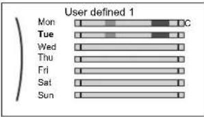
| 1 Select Monday. | ### | |
| User defined 1Mon Tue Wed Thu Fri Sat Sun | ||
| 2 Select Edit. | ### | |
 | ||
| 3 Use the left dial to select an entry and edit the entry with the right dial. You can program up to 6 actions each day. On the bar, a high temperature has a darker colour than a low temperature. | ### | |
 | ||
| Note: To clear an action, set its time as the time of the previous action. | ||
| 4 Confirm the changes. | ### | |
| Result: The schedule for Monday is defined. The value of the last action is valid until the next programmed action. In this example, Monday is the first day you programmed. Thus, the last programmed action is valid up to the first action of next Monday. | ||
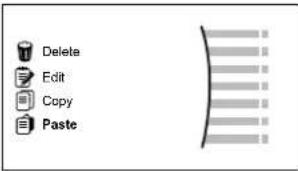
To copy the schedule to the other weekdays
1 Select Monday. | ### | |
2 Select Copy. Result: Next to the copied day, "C" is displayed. Result: Next to the copied day, "C" is displayed. | ### | |
3 Select Tuesday. | ### | |
| 4 Select Paste. | ### | |
 | ||
| Result: | ||
 | ||
| 5 Repeat this action for all other weekdays. | — | |
 | ||
To program the schedule for Saturday and copy it to Sunday
| 1 Select Saturday. | [R_n ·s O] | |
| 2 Select Edit. | [R_n ·s O] | |
3 Use the left dial to select an entry and edit the entry with the right dial.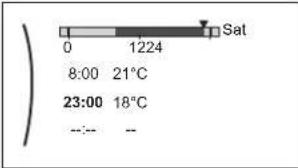 | [O ·s O O ·s O] | |
| 4 Confirm the changes. | [R_n ·s O] | |
| 5 Select Saturday. | [R_n ·s O] | |
| 6 Select Copy. | [R_n ·s O] | |
| 7 Select Sunday. | [R_n ·s O] | |
8 Select Paste.Result: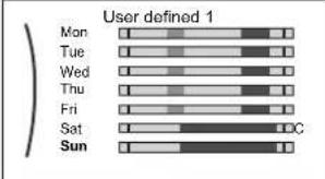 | [R_n ·s O] | |
To rename the schedule
1 Select the name of the current schedule.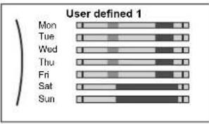 | ### | |
2 Select Rename. | ### | |
| 3 (optional) To delete the current schedule name, browse through the character list until ← is displayed, then press to remove the previous character. Repeat for each character of the schedule name. | ○··· | |
| 4 To name the current schedule, browse through the character list and confirm the selected character. The schedule name can contain up to 15 characters. | ○··· | |
| 5 Confirm the new name. | ### | |

INFORMATION
Not all schedules can be renamed.
Usage example: You work in a 3-shift system
If you work in a 3-shift system, you can do the following:
1 Program 3 room temperature schedules and give them appropriate names.
Example: EarlyShift, DayShift and LateShift
2 Select the schedule that you currently want to use.
5.8.4 Setting the energy prices
In the system, you can set the following energy prices:
- a fixed gas price
■ 3 electricity price levels - a weekly schedule timer for electricity prices.
Example: How to set the energy prices on the user interface?
| Price Value in breadcrumb | |
| Fuel: 5.3 euro cents/kWh [7.6]=5.3 | |
| Electricity: 12 euro cents/kWh [7.5.1]=12 |
To set the gas price
| 1 Go to [7.6]: User settings >Gas price. | 10...○ | |
| 2 Select the correct gas price. | 10...○ | |
| 3 Confirm the changes. | 10...○ | |

INFORMATION
Price value ranging from 0.00\~990 valuta/kWh (with 2 significant values).
To set the electricity price
| 1 | Go to [7.5.1]/[7.5.2]/[7.5.3]: User settings >Electricity price >High/Medium/Low. | ###...○ |
| 2 | Select the correct electricity price. | ###...○ |
| 3 | Confirm the changes. | ###...○ |
| 4 | Repeat this for all three electricity prices. — |

INFORMATION
Price value ranging from 0.00\~990 valuta/kWh (with 2 significant values).

INFORMATION
If no schedule is set, the Electricity price for High is taken into account.
To set the electricity price schedule timer
| 1 | Go to [7.5.4]: User settings > Electricity price > Schedule. | |
| 2 | Program the selection using the scheduling screen. You can set the High, Medium and Low electricity prices according to your electricity supplier. | — |
| 3 | Confirm the changes. |

INFORMATION
The values correspond with the electricity price values for High, Medium and Low previously set. If no schedule is set, the electricity price for High is taken into account.
About energy prices in case of an incentive per kWh renewable energy
An incentive can be taken into account when setting the energy prices. Although the running cost can increase, the total operation cost, taking into account the reimbursement will be optimized.

NOTICE
Make sure to modify the setting of the energy prices at the end of the incentive period.
To set the gas price in case of an incentive per kWh renewable energy
Calculate the value for the gas price with the following formula:
- Actual gas price+(Incentive/kWh×0.9)
For the procedure to set the gas price, see "To set the gas price" [▶ 41].
To set the electricity price in case of an incentive per kWh renewable energy
Calculate the value for the electricity price with following formula:
■ Actual electricity price+Incentive/kWh
For the procedure to set the electricity price, see "To set the electricity price" [▶ 42].
Example
This is an example and the prices and/or values used in this example are NOT accurate.
| Data Price/kWh | |
| Gas price 4.08 | |
| Electricity price 12.49 | |
| Renewable heat incentive per kWh 5 |
Calculation of the gas price
Gas price=Actual gas price+(Incentive/kWh×0.9)
Gas price=4.08+(5×0.9)
Gas price=8.58
Calculation of the electricity price
Electricity price=Actual electricity price+Incentive/kWh
Electricity price=12.49+5
Electricity price=17.49
| Price Value in breadcrumb | |
| Gas: 4.08 /kWh [7.6]=8.6 | |
| Electricity: 12.49 /kWh [7.5.1]=17 |
5.9 Weather-dependent curve
5.9.1 What is a weather-dependent curve?
Weather-dependent operation
The unit operates 'weather dependent' if the desired leaving water or tank temperature is determined automatically by the outdoor temperature. It therefore is connected to a temperature sensor on the North wall of the building. If the outdoor temperature drops or rises, the unit compensates instantly. Thus, the unit does not have to wait for feedback by the thermostat to increase or decrease the temperature of the leaving water or tank. Because it reacts more quickly, it prevents high rises and drops of the indoor temperature and water temperature at tap points.
Advantage
Weather-dependent operation reduces energy consumption.
Weather-dependent curve
To be able to compensate for differences in temperature, the unit relies on its weather-dependent curve. This curve defines how much the temperature of the tank or leaving water must be at different outdoor temperatures. Because the slope of the curve depends on local circumstances such as climate and the insulation of the house, the curve can be adjusted by an installer or user.
Types of weather-dependent curve
There are 2 types of weather-dependent curves:
2-points curve
- Slope-offset curve
Which type of curve you use to make adjustments, depends on your personal preference. See "5.9.4 Using weather-dependent curves" [▶ 46].
Availability
The weather-dependent curve is available for:
- Main zone - Heating
- Main zone - Cooling
■ Additional zone - Heating
■ Additional zone - Cooling - Tank (only available to installers)

INFORMATION
To operate weather dependent, correctly configure the setpoint of the main zone, additional zone or tank. See "5.9.4 Using weather-dependent curves" [▶ 46].
5.9.2 2-points curve
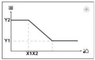
Define the weather-dependent curve with these two setpoints:
- Setpoint (X1, Y2)
- Setpoint (X2, Y1)
Example
line
| X-axis | Y-axis | |---|---| | 0 | Y2 | | X1X2 | Y1 | | End | Y1 || Item Description | |
| a Selected weather dependent zone:Main zone or additional zone heatingMain zone or additional zone coolingDomestic hot water | |
| X1, X2 Examples of outdoor ambient temperature | |
| Y1, Y2 Examples of desired tank temperature or leaving water temperature.The icon corresponds to the heat emitter for that zone:Underfloor heatingan coil unitRadiatorStorage tank |
| Possible actions on this screen | |
| ○⋯○ | Go through the temperatures. |
| ○⋯○ | Change the temperature. |
| ○⋯○ | Go to the next temperature. |
| ○⋯○ | Confirm changes and proceed. |
5.9.3 Slope-offset curve
Slope and offset
Define the weather-dependent curve by its slope and offset:
- Change the slope to differently increase or decrease the temperature of the leaving water for different ambient temperatures. For example, if leaving water temperature is in general fine but at low ambient temperatures too cold, raise the slope so that leaving water temperature is heated increasingly more at decreasingly lower ambient temperatures.
- Change the offset to equally increase or decrease the temperature of the leaving water for different ambient temperatures. For example, if leaving water temperature is always a bit too cold at different ambient temperatures, shift the offset up to equally increase the leaving water temperature for all ambient temperatures.
Examples
Weather-dependent curve when slope is selected:
line
| Point | Y1 | Y2 | Y3 | Y4 | |-------|-----|-----|-----|-----| | X1 | | | | | | X2 | | | | |Weather-dependent curve when offset is selected:

line
| X1X2 | Y1 | Y2 | Y3 | Y4 | |---|---|---|---|---| | 0 | 0 | 0 | 0 | 0 | | 1 | 0.5 | 0.75 | 0.625 | 0.875 | | 2 | 1 | 1.25 | 1.125 | 1.4 | | 3 | 1.5 | 1.75 | 1.625 | 1.95 | | 4 | 2 | 2.25 | 2.125 | 2.4 | | 5 | 2.5 | 2.75 | 2.625 | 2.95 | | 6 | 3 | 3.25 | 3.125 | 3.4 | | 7 | 3.5 | 3.75 | 3.625 | 3.95 | | 8 | 4 | 4.25 | 4.125 | 4.4 | | 9 | 4.5 | 4.75 | 4.625 | 4.95 | | 10 | 5 | 5.25 | 5.125 | 5.4 | | 11 | 5.5 | 5.75 | 5.625 | 5.95 | | 12 | 6 | 6.25 | 6.125 | 6.4 | | 13 | 6.5 | 6.75 | 6.625 | 6.95 | | 14 | 7 | 7.25 | 7.125 | 7.4 | | 15 | 7.5 | 7.75 | 7.625 | 7.95 | | 16 | 8 | 8.25 | 8.125 | 8.4 | | 17 | 8.5 | 8.75 | 8.625 | 8.95 | | 18 | 9 | 9.25 | 9.125 | 9.4 | | 19 | 9.5 | 9.75 | 9.625 | 9.95 | | 20 | 10 | 10.25 | 10.125 | 10.4 | | 21 | - | - | - | - | | 22 | - | - | - | - | | 23 | - | - | - | - | | 24 | - | - | - | - | | 25 | - | - | - | - | | 26 | - | - | - | - | | 27 | - | - | - | - | | 28 | - | - | - | - | | 29 | - | - | - | - | | 30 | - | - | - | - | | 31 | - | - | - | - | | 32 | - | - | - | - | | 33 | - | - | - | - | | 34 | - | - | - | - | | 35 | - | - | - | - | | 36 | - | - | - | - | | 37 | - | - | - | - | | 38 | - | - | - | - | | 39 | - | - | - | - | | 40 | - | - | - | - | | 41 | - | - | - | - | | 42 | - | - | - | - | | 43 | - | - | - | - | | 44 | - | - | - | - | | 45 | - | - | - | - | | 46 | - | - | - | - | | 47 | - | - | - | - | | 48 | - | - | - | - | | 49 | - | - | - | - | | 50+ (labeled on graph) — a → b → c → d → e → f → g → h → i → j → k → l → m → n → o → p → q → r → s → t → u → v → w → x → y → z → w + x + y + z → x + y + z + y + x + y + y + z + y + x + y + y + z + y + x + y + y + z + y + x + y + y + z + y + x + y + y + z + y + x + y + y + z + y + x + y + y + z + y + x + y + y + z + y + x + y + y + z + y + x + y + y + z + y + x + year + year + year + year + year + year + year + year + year + year + year + year + year + year + year + year + year + year + year + year + year + year + year + year + year + year + year + year + year + year + year + year + year + year + year + year + year + year + year + year + year + year + year + year + year + year + year + year + year + year + day × day × day × day × day × day × day × day × day × day × day × day × day × day × day × day × day × day × day × day × day × day × day × day × day × day × day × day × day × day × day × day × day × day × day × day × day × day × day × day × day × day × day × day × day × day × day × day × day × day × day = x (x-axis) for each data point, and for each data point, the corresponding value is plotted as a dashed line from left to right along the x-axis.| Item Description | |
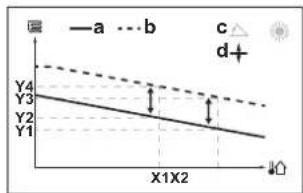
| a WD curve before changes. | |
| b WD curve after changes (as example): ·When slope is changed, the new preferred temperature at X1 unequally higher than the preferred temperature at X2. ·When offset is changed, the new preferred temperature at X1 is equally higher as the preferred temperature at X2. | |
| c Slope | |
| d Offset | |
| e Selected weather dependent zone: ·Main zone or additional zone heating ·Main zone or additional zone cooling ·Domestic hot water | |
| X1, X2 Examples of outdoor ambient temperature | |
| Y1, Y2, Y3, Y4 | Examples of desired tank temperature or leaving water temperature. The icon corresponds to the heat emitter for that zone: ·Underfloor heating ·Can coil unit ·Radiator ·Storage tank |
| Possible actions on this screen | |
| ○⋯○ | Select slope or offset. |
| ○⋯○ | Increase or decrease the slope/offset. |
| ○⋯○m | When slope is selected: set slope and go to offset.When offset is selected: set offset. |
| ○m⋯○ | Confirm changes and return to the submenu. |
5.9.4 Using weather-dependent curves
Configure weather-dependent curves as following:
To define the setpoint mode
To use the weather-dependent curve, you need to define the correct setpoint mode:
| Go to setpoint mode ... Set the setpoint mode to ... | |
| Main zone – Heating | |
| [2.4] Main zone >Setpoint mode WD | heating, fixed cooling OR Weather dependent |
| Main zone – Cooling | |
| [2.4] Main zone >Setpoint mode We | ather dependent |
| Additional zone – Heating | |
| [3.4] Additional zone >Setpoint mode | WD heating, fixed cooling OR Weather dependent |
| Additional zone – Cooling | |
| [3.4] Additional zone >Setpoint mode | Weather dependent |
| Tank | |
| [5.B] Tank >Setpoint mode | Restriction: Only available to installers. Weather dependent |
To change the type of weather-dependent curve
To change the type for all zones (main + additional) and for the tank, go to [2.E] Main zone >WD curve type.
Viewing which type is selected is also possible via:
- [3.C] Additional zone >WD curve type
- [5.E] Tank > WD curve type
Restriction: Only available to installers.
To change the weather-dependent curve
| Zone Go to ... | |
| Main zone – Heating | [2.5] Main zone > Heating WD curve |
| Main zone – Cooling | [2.6] Main zone > Cooling WD curve |
| Additional zone – Heating | [3.5] Additional zone > Heating WD curve |
| Additional zone – Cooling | [3.6] Additional zone > Cooling WD curve |
| Tank Restriction: Only available to installers.[5.C] Tank > WD curve | |

INFORMATION
Maximum and minimum setpoints
You cannot configure the curve with temperatures that are higher or lower than the set maximum and minimum setpoints for that zone or for the tank. When the maximum or minimum setpoint is reached, the curve flattens out.
To fine-tune the weather-dependent curve: slope-offset curve
The following table describes how to fine-tune the weather-dependent curve of a zone or tank:
| You feel ... Fine-tune with slope and offset: | |||
| At regular outdoor temperatures ... | At cold outdoor temperatures ... | Slope Offset | |
| OK Cold ↑ — | |||
| OK Hot ↓ — | |||
| Cold OK ↓ ↑ | |||
| Cold Cold — ↑ | |||
| Cold Hot ↓ ↑ | |||
| Hot OK ↑ ↓ | |||
| Hot Cold ↑ ↓ | |||
| Hot Hot — ↓ | |||
To fine-tune the weather-dependent curve: 2-points curve
The following table describes how to fine-tune the weather-dependent curve of a zone or tank:
| You feel ... Fine-tune with setpoints: | |||||
| At regular outdoor temperatures ... | At cold outdoor temperatures ... | Y2^(a) | Y1^(a) | X1^(a) | X2^(a) |
| OK Cold ↑ — | ↑ — | ||||
| OK Hot | ↓ — ↓ — | ||||
| Cold OK | — ↑ — ↑ | ||||
| Cold | Cold ↑ ↑ ↑ ↑ | ||||
| Cold | Hot | ↓ ↑ | ↓ ↑ | ||
| Hot OK | — ↓ — ↓ | ||||
| Hot | Cold ↑ ↓ ↑ ↓ | ||||
| Hot Hot | ↓ ↓ ↓ ↓ | ||||
(a) See "5.9.2 2-points curve" [▶ 44].
5.10 Other functionalities
5.10.1 To configure time and date
| 1 | Go to [7.2] User settings > Time/date. | 10...○ |
5.10.2 Using quiet mode
About quiet mode
You can use quiet mode to decrease the sound of the outdoor unit. However, this also decreases the heating/cooling capacity of the system. There are multiple quiet mode levels.
You can:
■ Completely deactivate quiet mode
- Manually activate a quiet mode level until the next scheduled action
- Use and program a quiet mode schedule

INFORMATION
If the outdoor temperature is below zero, we recommend to NOT use the most quiet level.
To check if quiet mode is active
If 1 is displayed on the home screen, quiet mode is active.
To program a quiet mode schedule
Restriction: Only possible if enabled by the installer.
| 1 | Go to [7.4.2]: User settings >Quiet >Schedule. | ### |
| 2 | Program the schedule.Possible actions: You can use the following system-defined preset values:▪ Quiet▪ More quiet▪ Most quietFor more information about scheduling, see "5.8.2 Using and programming schedules" [ ▶ 34]. | — |
5.10.3 Using holiday mode
About holiday mode
During your holiday, you can use the holiday mode to deviate from your normal schedules without having to change them. While holiday mode is active, space heating/cooling operation and domestic hot water operation will be turned off. Room frost protection and anti-legionella operation will remain active.
Typical workflow
Using holiday mode typically consists of the following stages:
1 Setting the starting date and ending date of your holiday.
2 Activating the holiday mode.
To check if holiday mode is activated and/or running
If displayed on the home screen, holiday mode is active.
To configure the holiday
| 1 Activate the holiday mode. — | |
Go to [7.3.1]: User settings >Holiday >Activation.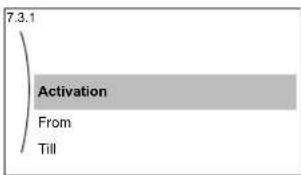 | ###...○ |
| Select On. | ###...○ |
| 2 Set the first day of your holiday. — | |
| Go to [7.3.2]: From. | ###...○ |
| Select a date. | [●···○○···○] |
| Confirm the changes. | ###...○ |
| 3 Set the last day of your holiday. — | |
| Go to [7.3.3]: Till. | ###...○ |
| Select a date. | [●···○○···○] |
| Confirm the changes. | ###...○ |
5.10.4 Using WLAN

INFORMATION
Restriction: WLAN settings are only visible when a WLAN module is installed.
About the WLAN module
The wireless LAN module connects the heat pump system to the internet. As user you can then control the heat pump system via the Daikin Residential Controller app.
This needs the following components:

flowchart
graph TD
    A["OR"] --> B["abc"]
    B --> C["Router"]
    C --> D["WWW"]
    D --> E["Mobile Phone"]
| a WLAN module The WLAN | module needs to be installed by the installer on the indoor unit (on the inside of the front panel). |
| b Router Field supply. |
c Smartphone + app The Daikin Residential Controller app needs to be

installed on the user's smartphone. See:
http://www.onlinecontroller.daikineurope.com/

Configuration
To configure the Daikin Residential Controller app, follow the in-app instructions. While doing this, the following actions and information are needed on the user interface of the indoor unit:
text_image
User profile Operation Wireless gateway Malfunctioning Room[D] Wireless gateway
[D.1] Mode
[D.2] WPS
[D.3] Reboot
[D.4] Device info
[D.1] Mode: Turn AP mode ON (= WLAN module active as access point):
| 1 Go to [D.1]: Wireless gateway > Mode. | ### | |
| 2 In the Enable AP mode screen, select Yes. | ### | |
[D.2] WPS: Connect the WLAN module to the router:
| 1 | Go to [D.2]: Wireless gateway >WPS. | ### |
| 2 | In the Connect to home network screen, select OK. | ### |
[D.3] Reboot: Reset the WLAN module:
| 1 Go to [D.3]: Wireless gateway > Reboot. | ### | |
| 2 | In the Reboot the gateway screen, select OK. | ### |
[D.4] Device info: Consult information about the WLAN module:
| 1 | Go to [D.4]: Wireless gateway >Device info. | 10...○ |
| 2 | Read out SSID, MAC address, and Serial number. | 10...○ |

INFORMATION
Restriction: WLAN settings are only visible when a WLAN cartridge is inserted in the user interface.
About the WLAN cartridge
The WLAN cartridge connects the system to the internet. As user you can then control the system via the Daikin Residential Controller app.
This needs the following components:
| a WLAN cartridge The WLAN | cartridge needs to be inserted in the user interface. |
| b Router Field supply. |
c Smartphone + app The Daikin Residential Controller app needs to be
installed on the user's smartphone. See:
http://www.onlinecontroller.daikineurope.com/


Configuration
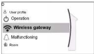
To configure the Daikin Residential Controller app, follow the in-app instructions. While doing this, the following actions and information are needed on the user interface:

text_image
User profiles Operation Wireless gateway Malfunctioning Room[D] Wireless gateway
[D.1] Mode
[D.2] Reboot
[D.3] WPS
[D.4] Remove from cloud
[D.5] Home network connection
[D.6] Cloud connection
[D.1] Mode: Turn AP mode ON (= WLAN cartridge active as access point):
| 1 | Go to [D.1]: Wireless gateway > Mode. | ###...○ |
| 2 | In the Enable AP mode screen, select Yes. | ###...○ |
[D.2] Reboot: Reboot the WLAN cartridge:
| 1 | Go to [D.2]: Wireless gateway > Reboot. | ### |
| 2 | In the Reboot the gateway screen, select OK. | ### |
[D.3] WPS: Connect the WLAN cartridge to the router:

INFORMATION
You can only use this function if it is supported by the software version of the WLAN, and the software version of the Daikin Residential Controller app.
| 1 | Go to [D.3]: Wireless gateway >WPS. | |
| 2 | In the WPS screen, select Yes. |
[D.4] Remove from cloud: Remove the WLAN cartridge from the cloud:
| 1 | Go to [D.4]: Wireless gateway > Remove from cloud. | ### |
| 2 | In the Remove from cloud screen, select Yes. | ### |
[D.5] Home network connection: Read out the status of the connection to the home network:
| 1 | Go to [D.5]: Wireless gateway > Home network connection. | |
| 2 | Read out the connection status:• Disconnected from [WLAN_SSID]• Connected to [WLAN_SSID] |
[D.6] Cloud connection: Read out the status of the connection to the cloud:
| 1 | Go to [D.6]: Wireless gateway >Cloud connection. | t_R... |
| 2 | Read out the connection status:Not connectedConnected | t_R... |
6 Energy saving tips
Tips about room temperature
- Make sure the desired room temperature is NEVER too high (in heating mode) or too low (in cooling mode), but ALWAYS according to your actual needs. Each saved degree can save up to 6% of heating/cooling costs.
- Do NOT increase/decrease the desired room temperature to speed up space heating/cooling. The space will NOT heat up/cool down faster.
- When your system layout contains slow heat emitters (example: underfloor heating), avoid large fluctuation of the desired room temperature and do NOT let the room temperature drop too low/rise too high. It will take more time and energy to heat up/cool down the room again.
- Use a weekly schedule for your normal space heating or cooling needs. If necessary, you can easily deviate from the schedule:
- For shorter periods: You can overrule the scheduled room temperature until the next scheduled action. Example: When you have a party, or when you are leaving for a couple of hours.
- For longer periods: You can use the holiday mode.
Tips about leaving water temperature
- In heating mode, a lower desired leaving water temperature results in lower energy consumption and better performance. In cooling, the opposite is valid.
- Set the desired leaving water temperature in accordance with the heat emitter type. Example: Underfloor heating is designed for lower leaving water temperature than radiators and heat pump convectors.
Tips about DHW temperature
- Make sure the desired DHW temperature, reflected by storage tank temperature, is NOT too high. Example: After installation, lower the tank temperature daily by 1°C and check if you still have enough hot water.
- Program to turn ON the domestic hot water pump ONLY during periods of the day when instant hot water is necessary. Example: In the morning and evening.
7 Maintenance and service
7.1 Overview: Maintenance and service
The installer has to perform a yearly maintenance. You can find the contact/helpdesk number via the user interface.
1 Go to [8.3]: Information > Dealer information.
10...
As end user, you have to:
- Keep the area around the unit clean.
- Keep the user interface clean with a soft damp cloth. Do NOT use any detergents.
- Regularly check if the water pressure is above 1 bar.
- Carry out a visual check of the water level inside the storage tank: Check if the red level indicator is visible. If NOT, add water to the storage tank (for details see Installer reference guide).
Refrigerant
This product contains fluorinated greenhouse gases. Do NOT vent gases into the atmosphere.
Refrigerant type: R32
Global warming potential (GWP) value: 675

NOTICE
Applicable legislation on fluorinated greenhouse gases requires that the refrigerant charge of the unit is indicated both in weight and CO₂ equivalent.
Formula to calculate the quantity in CO_2 equivalent tonnes: GWP value of the refrigerant × total refrigerant charge [in kg] / 1000
Please contact your installer for more information.

WARNING: FLAMMABLE MATERIAL
The refrigerant inside this unit is mildly flammable.

WARNING
- Do NOT pierce or burn refrigerant cycle parts.
- Do NOT use cleaning materials or means to accelerate the defrosting process other than those recommended by the manufacturer.
- Be aware that the refrigerant inside the system is odourless.

WARNING
The refrigerant inside the unit is mildly flammable, but normally does NOT leak. If the refrigerant leaks in the room and comes in contact with fire from a burner, a heater, or a cooker, this may result in fire, or the formation of a harmful gas.
Turn off any combustible heating devices, ventilate the room, and contact the dealer where you purchased the unit.
Do NOT use the unit until a service person confirms that the part from which the refrigerant leaked has been repaired.
8 Troubleshooting
Contact
For the symptoms listed below, you can try to solve the problem yourself. For any other problem, contact your installer. You can find the contact/helpdesk number via the user interface.
| 1 | Go to [8.3]: Information >Dealer information. |
8.1 To display the help text in case of a malfunction
In case of a malfunction, the following will appear on the home screen depending on the severity:
Error
Malfunction
You can get a short and a long description of the malfunction as follows:
| 1 Press the left dial to open the main menu and go to Malfunctioning.Result: A short description of the error and the error code is displayed on the screen. | ### |
| 2 Press in the error screen.Result: A long description of the error is displayed on the screen. | ? |
8.2 To check the malfunction history
Conditions: The user permission level is set to advanced end user.
| 1 | Go to [8.2]: Information >Malfunction history. |
You see a list of the most recent malfunctions.
8.3 Symptom: You are feeling too cold (hot) in your living room
| Possible cause Corrective action | |
| The desired room temperature is too low (high). | Increase (decrease) the desired room temperature. See "5.6.4 To change the desired room temperature" [▶ 29].If the problem recurs daily, do one of the following:▪ Increase (decrease) the room temperature preset value. See "5.8.1 Using preset values" [▶ 34].▪ Adjust the room temperature schedule. See "5.8.2 Using and programming schedules" [▶ 34] and "5.8.3 Schedule screen: Example" [▶ 37]. |
| The desired room temperature cannot be reached. | Increase the desired leaving water temperature in accordance with the heat emitter type. See "5.6.5 To change the desired leaving water temperature" [▶ 29]. |
| The weather-dependent curve is set incorrectly. | Adjust the weather-dependent curve.See "5.9 Weather-dependent curve" [▶ 43]. |
8.4 Symptom: The water at the tap is too cold
| Possible cause Corrective action | |
| You ran out of domestic hot water because of unusual high consumption. | If you immediately need domestic hot water, activate the tankPowerful operation. However, this consumes extra energy. See "5.7.5 Using DHW powerful operation" [▶ 33].If the problems recurs daily, do one of the following:Adjust the storage tank temperature schedule. See "5.8.2 Using and programming schedules" [▶ 34] and "5.8.3 Schedule screen:Example" [▶ 37]. |
| The desired storage tank temperature is too low. | |
8.5 Symptom: Heat pump failure
When the heat pump fails to operate, the backup heater or boiler can serve as an emergency heater. It then takes over the heat load either automatically or by manual interaction.
- When Emergency is set to Automatic and a heat pump failure occurs, the backup heater or boiler automatically takes over the domestic hot water production and space heating.
- When Emergency is set to Manual and a heat pump failure occurs, the domestic hot water heating and space heating stops.
To manually recover it via the user interface, go to the Malfunctioning main menu screen and confirm whether the backup heater can take over the heat load or not.
■ Alternatively, when Emergency is set to:
- auto SH reduced/DHW on, space heating is reduced but domestic hot water is still available.
- auto SH reduced/DHW off, space heating is reduced and domestic hot water is NOT available.
- auto SH normal/DHW off, space heating operates as normally but domestic hot water is NOT available.
Similarly as in Manual mode, the unit can take the full load with the backup heater or boiler if the user activates this via the Malfunctioning main menu screen.
When the heat pump fails, or will appear on the user interface.
| Possible cause Corrective action | |
| Heat pump is damaged. See "8.1 To display the help text in case of a malfunction" [▶ 56]. |

INFORMATION
When the backup heater takes over the heat load, electricity consumption will be considerably higher.
8.6 Symptom: The system is making gurgling noises after commissioning
| Possible cause Corrective action | |
| There is air in the system. | Purge air from the system. ^(a) |
| Incorrect hydraulic balance. | To be performed by the installer:1 Perform hydraulic balancing to assure that the flow is correctly distributed between the emitters.2 If hydraulic balancing is not sufficient, change the pump limitation settings ([9-0D] and [9-0E] if applicable). |
| Various malfunctions. | Check iforisdisplayed on the home screen of the user interface. See "8.1 To display the help text in case of a malfunction" [▶ 56] for more information about the malfunction. |
^[a] We recommend to purge air with the air purge function of the unit (to be performed by the installer). If you purge air from the heat emitters or collectors, mind the following:

WARNING
Air purging heat emitters or collectors. Before you purge air from heat emitters or collectors, check if or is displayed on the home screen of the user interface.
- If not, you can purge air immediately.
- If yes, make sure that the room where you want to purge air is sufficiently ventilated. Reason: Refrigerant might leak into the water circuit, and subsequently into the room when you purge air from the heat emitters or collectors.
9 Relocation
9.1 Overview: Relocation
If you want to relocate parts of your system, contact your installer. You can find the contact/helpdesk number via the user interface.
| 1 | Go to [8.3]: Information >Dealer information. | ### |
10 Disposal

NOTICE
Do NOT try to dismantle the system yourself: dismantling of the system, treatment of the refrigerant, oil and other parts MUST comply with applicable legislation. Units MUST be treated at a specialised treatment facility for reuse, recycling and recovery.
11 Glossary
DHW = Domestic hot water
Hot water used, in any type of building, for domestic purposes.
LWT = Leaving water temperature
Water temperature at the water outlet of the unit.
Dealer
Sales distributor for the product.
Authorised installer
Technical skilled person who is qualified to install the product.
User
Person who is owner of the product and/or operates the product.
Applicable legislation
All international, European, national and local directives, laws, regulations and/or codes that are relevant and applicable for a certain product or domain.
Service company
Qualified company which can perform or coordinate the required service to the product.
Installation manual
Instruction manual specified for a certain product or application, explaining how to install, configure and maintain it.
Operation manual
Instruction manual specified for a certain product or application, explaining how to operate it.
Accessories
Labels, manuals, information sheets and equipment that are delivered with the product and that need to be installed according to the instructions in the accompanying documentation.
Optional equipment
Equipment made or approved by Daikin that can be combined with the product according to the instructions in the accompanying documentation.
Field supply
Equipment NOT made by Daikin that can be combined with the product according to the instructions in the accompanying documentation.
12 Installer settings: Tables to be filled in by installer
12.1 Configuration wizard
| Setting Fill in... | ||
| System | ||
| Indoor unit type (read only) | ||
| Backup heater type [9.3.1] (read only) | ||
| Domestic hot water [9.2.1] | ||
| Emergency [9.5] | ||
| Number of zones [4.4] | ||
| Glycol Filled system (overview field setting [E-0D]) | ||
| Solar [9.2.4] | ||
| Backup heater | ||
| Voltage [9.3.2] | ||
| Configuration [9.3.3] | ||
| Capacity step 1 [9.3.4] | ||
| Additional capacity step 2 [9.3.5] (if applicable) | ||
| Main zone | ||
| Emitter type [2.7] | ||
| Control [2.9] | ||
| Setpoint mode [2.4] | ||
| Schedule [2.1] | ||
| WD curve type [2.E] | ||
| Additional zone (only if [4.4]=1, dual zone) | ||
| Emitter type [3.7] | ||
| Control (read only) [3.9] | ||
| Setpoint mode [3.4] | ||
| Schedule [3.1] | ||
| WD curve type [3.C] (read only) | ||
| Tank | ||
| Heat up mode [5.6] | ||
| Hysteresis [5.9] | ||
12.2 Settings menu
| Setting Fill in... | ||
| Main zone | ||
| Thermostat type [2.A] | ||
| Additional zone (if applicable) | ||
| Thermostat type [3.A] | ||
| Information | ||
| Dealer information [8.3] | ||


natural_image
Blank grid paper with no text, numbers, or symbols

natural_image
Blank grid paper with no text, numbers, or symbols
