ERP01A51 - Air-conditioner DAIKIN - Free user manual and instructions
Find the device manual for free ERP01A51 DAIKIN in PDF.

User questions about ERP01A51 DAIKIN
0 question about this device. Answer the ones you know or ask your own.
Ask a new question about this device
Download the instructions for your Air-conditioner in PDF format for free! Find your manual ERP01A51 - DAIKIN and take your electronic device back in hand. On this page are published all the documents necessary for the use of your device. ERP01A51 by DAIKIN.
USER MANUAL ERP01A51 DAIKIN
natural_image
Front view of an electronic device casing with labeled components (X5A, X11–X14) and mounting holes (no text or symbols beyond labels)Be sure to read this manual before installation and follow the instruction.
Accessories
Check if the following accessories are included:
| Name Adaptor PCB | Support | Clamp Installation manual | Wire harness | |
| Shape |  | 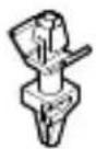 | 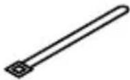 |  |
| Quantity | 1x 4x 3x 1x 1x | |||
Electric wiring
- Make sure wires to units do not pass over the PC board when wiring.
- Wire the adaptor to the indoor unit as described below.

text_image
X5A X14 X12 X11 X13 X12 X40A Indoor unit PC boardReceiving the operation signal
Attaching an alarm

text_image
Example: X11 X12 A: Alarm (field supply) AC 220~240V A: Alarm (field supply)Attaching a ventilation system

text_image
Example: X13 X14 V: Ventilation system (field supply) AC 220~240V VWhen installing the external safety device (alarm, ventilation) as field supply, connect it via this relay PCB.
Caution
Regarding selection of alarm and ventilation, select its specification according to local regulations
- Only the operation ON signal is output from the indoor unit.
- When an abnormality occurs, the external safety device starts and continues to operate. Provide another means to stop the external safety device (no stop signal is provided from indoor unit).
- Relay PCB contact specifications: stable state current 1A (RMS), inrush current 3A (peak).
If installer needs to connect external device with electric current more than 1A, it is recommended to connect the device according to diagram below.

flowchart
graph TD
    A["Relay PCB"] --> B["X1M"]
    B --> C["Electromagnetic relay"]
    C --> D["External device with current more than 1A"]
    C --> E["AC 220-240V"]
    style A fill:#f9f,stroke:#333
    style B fill:#ccf,stroke:#333
    style C fill:#cfc,stroke:#333
    style D fill:#fcc,stroke:#333
    style E fill:#cff,stroke:#333
Local setting
It is necessary to change settings in the remote controller.
| If you want to change increments to... | Then | ||
| M SW | - | ||
| Disenable | 15 (25) 15 | 01 (default setting) | |
| Enable 02 | |||
Installation
- Do not bundle low and high voltage wires together.
- Bundle any excess wires with the attached tie wraps to keep loose wirings off the indoor unit PC board.
Note: Installation box for adaptor PCB is required to install the adaptor. For installation details regarding attaching of the box to the unit refer to the installation manual provided with the installation box.

natural_image
Simple line drawing of a pen writing on a line (no text or symbols present)| 10000000000000000000000000000000000000000000000000000000000000000000000000000000000000000000000000000 | ||||||||||||||||
DAIKIN INDUSTRIES CZECH REPUBLIC s.r.o.
U Nové Hospody 1/1155, 301 00 Plzeň Skvrňany, Czech Republic