Motif Risplendi 150 - Projector Blizzard - Free user manual and instructions
Find the device manual for free Motif Risplendi 150 Blizzard in PDF.

User questions about Motif Risplendi 150 Blizzard
0 question about this device. Answer the ones you know or ask your own.
Ask a new question about this device
Download the instructions for your Projector in PDF format for free! Find your manual Motif Risplendi 150 - Blizzard and take your electronic device back in hand. On this page are published all the documents necessary for the use of your device. Motif Risplendi 150 by Blizzard.
USER MANUAL Motif Risplendi 150 Blizzard
natural_image
Black adjustable lighting fixture with green light source, no visible text or symbols on body
blizzard
Blizzard Lighting, LLC
http://www.blizzardpro.com
Waukesha, WI USA
Copyright (c) 2023
TABLE OF CONTENTS
1. Getting Started 3
What's In The Box? 3
Getting It Out Of the Box 3
Powering Up! 3
Getting A Hold Of Us 3
Safety Instructions 4
2. Meet the Motif™ Risplendi 150 5
Main Features 5
Motif™ Risplendi 150 Pin-Up Picture 6
The Rear Connections 6
3. Setup 7
Fuse Replacement 7
Power Input 7
Connecting the Fixtures 7
Cable Connectors 8
3-Pin??? 5-Pin??? Huh?!? 8
Take It To The Next Level: Setting Up DMX Control 8
Changing the Lenses 9
Installing or Removing Brackets 9
Mounting & Rigging 9
4. Operating Adjustments 10
The Control Panel 10
Control Panel Menu Structure 11
DMX Mode 12
Dimming Mode Settings 12
Custom Programs 13
Auto, Modes, and Auto Speed 13
Color Calibration Settings 14
Custom Static Colors & Preset Colors 14
Fixture Reset Functions 15
Data Sync Feature 15
Fixture Information 15
DMX Values In-Depth 16
Troubleshooting 17
5. Appendix 18
Keeping Your Motif™ Risplendi As Good As New 18
Returns (Gasp!) 18
Shipping Issues 18
Tech Specs! 19
Dimensional Drawings 20
1. GETTING STARTED
What's In The Box?
• Motif™ Risplendi 150
- Power cable
- 4x interchangeable lenses
• This user manual
Optional Accessories (sold separately)
The Motif™ Risplendi 150 allows for an optional full snoot accessory which can enhance the light's output control by concentrating its beam spread. Contact your authorized Blizzard Lighting dealer for pricing.
- Black Housing: SNOOT-Motif Risplendi (B)
• White Housing: SNOOT-Motif Risplendi (W)
• Space Gray Housing: SNOOT-Motif Risplendi (SG)
Getting It Out Of the Box
Congratulations on purchasing the Motif™ Risplendi 150. Now that you've got your fixture, you should carefully unpack the box and check the contents to ensure that all parts are present and in good condition. If anything looks as if it has been damaged in transit, notify the shipper immediately and keep the packing material for inspection. Again, please save the carton and all packing materials. If a fixture must be returned to the factory, it is important that the fixture be returned in the original factory box and packing.
Powering Up!
All fixtures must be powered directly off a switched circuit and cannot be run off a rheostat (variable resistor) or dimmer circuit, even if the rheostat or dimmer channel is used solely for a 0% to 100% switch.
Warning! All fixtures must be connected to circuits with a suitable Ground (Earthing).
Getting A Hold Of Us
If something happens to go wrong, visit blizzardpro.com/support and open a support ticket. We'll be happy to help, honest.
Disclaimer: The information contained in this document are subject to change without notice. Blizzard Lighting™ assumes no responsibility or liability for any errors or omissions that may appear in this user manual. We reserve the right to update the existing, or create a new document to correct any errors or omissions at any time. You can download the latest version of this document from www.blizzardpro.com.
| Author: Date: Last Edited: Date: | ||
| J. Thomas 6/13/2023 J. Thomas 6/27/2023 |

text_image
Yellow triangular warning sign with black exclamation mark symbolPlease read these instructions carefully. They include important information about the installation, usage and maintenance of this product.
- Please keep this User Guide for future use. If you sell the unit to someone else, be sure that they also receive this User Guide.
- ALWAYS make sure that you are connecting to the proper voltage, and that the line voltage you are connecting to is not higher than that stated on the decal or rear panel of the fixture.
- This product is intended for indoor use only.
- To prevent risk of fire or shock, do not expose fixture to rain or moisture.
- Make sure there are no flammable materials close to the unit while operating.
- The unit must be installed in a location with adequate ventilation, at least 20in (50cm) from adjacent surfaces. Be sure that no ventilation slots are blocked.
- ALWAYS disconnect from the power source before servicing or replacing fuse and be sure to replace with same fuse size and type.
- ALWAYS secure fixture using a safety chain. NEVER carry the fixture by its head. Use its carrying handles.
- DO NOT operate at ambient temperatures higher than 104^ (40°C).
- In the event of a serious operating problem, stop using the unit immediately. NEVER try to repair the unit by yourself. Repairs carried out by unskilled people can lead to damage or malfunction. Please contact the nearest authorized technical assistance center. Always use the same type spare parts.
- NEVER connect the device to a dimmer pack.
- Make sure the power cord is never crimped or damaged.
- Never disconnect the power cord by pulling or tugging on the cord.
- Avoid direct eye exposure to the light source while it is on.
Caution! There are no user serviceable parts inside the unit. Do not open the housing or attempt any repairs yourself. In the unlikely event your unit may require service, please open a support ticket at www.blizzardpro.com/support.
2. MEET THE MOTIF™ RISPLENDI 150
Main Features
• Light source: 150W RGBAL COB LED, 100,000 hrs.
• Built-in color & chase macros via DMX
• Built-in automated programs via master/slave
• Color mixing ability in standalone mode
- 4x light collimating lenses (30°, 45°, 60°, 80°)
- Convection cooled aluminum housing
- Dual mounting brackets for positioning flexibility
- Adjustable LED refresh rates (1200Hz-20KHz)
- PowerCON® TRUE1™ compatible + hardwire AC connector
• Emergency power backup connector (42-48V DC, 20W)
- 5-pin male/female XLR input & output connections
Control
- Protocol: USITT DMX-512, RDM
• DMX channels: 5/7/11-channels - OLED control menu with 4x touch sensitive buttons
- Operating modes: DMX512, master/slave, auto
DMX Quick Reference (5-Channel Mode)
| Channel What is does... | |
| 1 Red Intensity (0 <--> 100%) | |
| 2 Green Intensity (0 <--> 100%) | |
| 3 Blue Intensity (0 <--> 100%) | |
| 4 Amber Intensity (0 <--> 100%) | |
| 5 Lime Intensity (0 <--> 100%) |
DMX Quick Reference (7-Channel Mode)
| Channel What is does... | |
| 1 Master Dimmer (0 <--> 100%) | |
| 2 Red Intensity (0 <--> 100%) | |
| 3 Green Intensity (0 <--> 100%) | |
| 4 Blue Intensity (0 <--> 100%) | |
| 5 Amber Intensity (0 <--> 100%) | |
| 6 Lime Intensity (0 <--> 100%) | |
| 7 Strobe (Slow <--> Fast) |
DMX Quick Reference (11-Channel Mode)
| Channel What is does... | |
| 1 Master Dimmer (0 <--> 100%) | |
| 2 Red Intensity (0 <--> 100%) | |
| 3 Green Intensity (0 <--> 100%) | |
| 4 Blue Intensity (0 <--> 100%) | |
| 5 Amber Intensity (0 <--> 100%) | |
| 6 Lime Intensity (0 <--> 100%) | |
| 7 Strobe (Slow <--> Fast) | |
| 8 Built-In Programs | |
| 9 Auto Speed (Slow <--> Fast) | |
| 10 Virtual Color Wheel | |
| 11 32-Bit Dimming |
Motif™ Risplendi 150 Pin-Up Picture
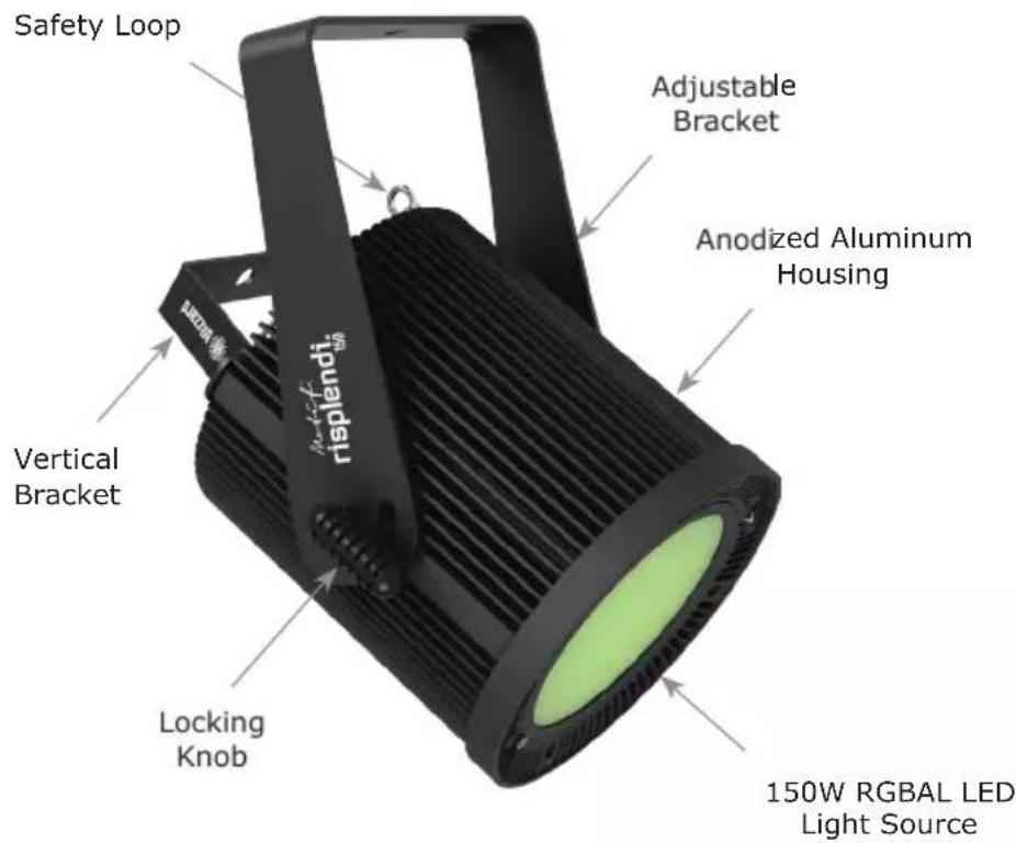
text_image
Safety Loop Adjustable Bracket Anodized Aluminum Housing Vertical Bracket Locking Knob 150W RGBAL LED Light SourceThe Rear Connections
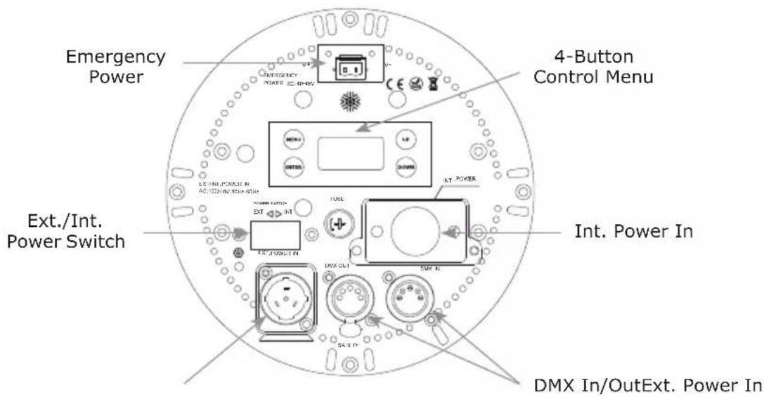
text_image
Emergency Power 4-Button Control Menu Ext./Int. Power Switch Int. Power In DMX In/OutExt. Power In3. SETUP

text_image
Yellow triangular warning sign with black exclamation mark symbolBefore replacing the fuse, disconnect the power cord. ALWAYS replace it with the same type and rating.
Fuse Replacement
Remove the fuse holder from of its housing. Take out the damaged fuse from its holder and replace with exact same type of fuse.
Power Inputs
This fixture comes with a powerCON® TRUE1™ compatible power input and a 3-wire power terminal block connector located under the "Int. Power In" cover plate on the rear of the fixture that can be used for hardwiring power.
Depending on which method you use, adjust the external/internal power switch on the back of the unit to select the proper input source.
Use the table below for reference when using the bare wire:
| Connection Wire (U.S.) | Wire (Europe) Screw Color | |
| AC Live Black Brown Yellow | or Brass | |
| AC Neutral White Blue Silver | ||
| AC Ground Green/Yellow | Green/Yellow | Green |
Connecting the Fixtures
Fixtures on a serial data link must be daisy chained in one single line. Also, connecting more than 32 fixtures on one serial data link without the use of a DMX optically-isolated splitter may result in deterioration of the signal.
Data/DMX Cabling
To link fixtures together you'll need data cables. You should use data-grade cables that can carry a high quality signal.
The data cable should have the following characteristics:
• 2-conductor twisted pair plus a shield
• Maximum capacitance between conductors - 30 pF/ft.
• Maximum capacitance between conductor & shield - 55 pF/ft.
• Maximum resistance of 20 ohms / 1000 ft.
• Nominal impedance 100 - 140 ohms
Cable Connectors
Cables must have a male XLR connector on one end and a female XLR connector on the other end. (Duh!)
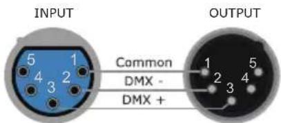
text_image
INPUT Common DMX - DMX + OUTPUTA Word on Termination:
DMX is a resilient communication protocol, however errors still occasionally occur. Termination reduces signal errors, and therefore best practices include use of a terminator in all circumstances. If you are experiencing problems with erratic fixture behavior, especially over long signal cable runs, a terminator may help improve performance.
To build your own DMX Terminator:
Obtain a 120-ohm, 1/4-watt resistor, and wire it between pins 2 & 3 of the last fixture. They are also readily available from specialty retailers.
CAUTION: Do not allow contact between the common and the fixture's chassis ground. Grounding the common can cause a ground loop, and your fixture may perform erratically. Test cables with an ohm meter to verify correct polarity and to make sure the pins are not grounded or shorted to the shield or each other.
3-Pin??? 5-Pin??? Huh?!?
If you use a controller with a 3-pin DMX output connector, you will need to use a 3-pin to 5-pin adapter. If you'd like to build your own, the chart below details a proper cable conversion:
| Conductor 3-Pin Female (Output) 5-Pin Male (Input) | |
| Ground/Shield Pin 1 Pin 1 | |
| Data 1- (Primary Data) Pin 2 Pin 2 | |
| Data 1+ (Primary Data) Pin 3 Pin 3 | |
| Data 2- (Optional) -- Pin 4 - Do Not Use | |
| Data 2+ (Optional) -- Pin 5 - Do Not Use |
Take It To The Next Level: Setting Up DMX Control
Step 1: Connect the male connector of the DMX cable to the female connector (output) on the controller.
Step 2: Connect the female connector of the DMX cable to the first fixture's male connector (input).
Note: It doesn't matter which fixture address is the first one connected. We recommend connecting the fixtures in terms of their proximity to the controller, rather than connecting the lowest fixture number first, and so on.
Step 3: Connect other fixtures in the chain from output to input as above. Place a DMX terminator on the output of the final fixture to ensure best communication.

text_image
First Fixture in Chain DMX IN DMX OUT Next Fixture in Chain DMX IN DMX OUTChanging the Lenses
This fixture comes with a pre-installed 80° diffuser lens plus 3x replaceable Fresnel lenses (30°, 45°, and 60°) for a variety of beam angles.
To change the lens, remove the thumbscrew from the lens holder and swivel the holder outwards. Replace the existing lens with the lens of your choice.
Note: The replaceable lenses need to be installed with the circular pattern side of the lens facing outwards.
*When using lenses with narrower beam angles, some chromatic aberration (color separation) may occur. We recommend using the snoot accessory (sold separately) to cut off the beam edge. This may help in certain circumstances.
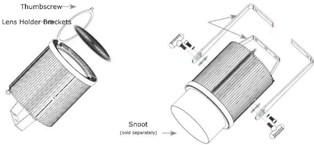
text_image
Thumbscrew Lens Holder Brackets Snoot (sold separately)Installing or Removing Brackets
1.) Install or remove the brackets as shown above using the included bolts, washers, and knobs.
2.) Use the small bracket for vertically mounted fixed installations. You can remove the large bracket in these types of applications, and use the included plastic plugs to cover the bracket screw holes.
Mounting & Rigging
This fixture may be mounted in any SAFE position provided there is enough room for ventilation.

natural_image
Technical line drawing of a mechanical assembly with a suspended hook and vertical supports (no text or symbols)Mount the fixture using a suitable "C" or "O" type clamp. The clamp should be rated to hold at least 10x the fixture's weight to ensure structural stability. Do not mount to surfaces of unknown strength, ensure properly rated rigging is used, and always secure your fixtures with a safety cable.
4. OPERATING ADJUSTMENTS
The Control Panel
All of the features and different modes possible with this fixture are accessed by using the control panel on the front of the fixture. There are 4 control buttons next to the menu display which allow you to navigate through the various control panel menus.
Is used to navigate to the previous higher-level menu item.
Is used to select and confirm/store the current selection.
Scrolls through menu items and numbers in ascending order.
Scrolls through menu items and numbers in descending order.

flowchart
graph TD
    A["MAIN ADDR=001"] --> B["MENU"]
    A --> C["UP"]
    A --> D["ENTER"]
    A --> E["DOWN"]
The control panel display shows the menu items you select from the menu map on page #11. When a menu function is selected, the display will show immediately the first available option for the selected menu function. To select a menu item, press
Use the
Control Panel Menu Structure
| ADDR 001-512 To choose the DMX | address | |||
| STAT R | Red intensity (0% <--> 10%) | |||
| G Green intensity (0% <--> 100%) | ||||
| B Blue intensity (0% <--> 100%) | ||||
| A Amber intensity (0% <--> 100%) | ||||
| L Lime intensity (0% <--> 100%) | ||||
| SHUT Flash / strobe speed | (0-255) | |||
| PRSC (preset colors) | NONE, R, G, B, A, L, RGBAL, YELLOW, PINK, CYAN, ORANGE, VIO-LET, GOLDEN, 2700K, 3200K, 4000K, 5500K, 6500K, RGBL | |||
| SET CAL | To set global intensity levels of each color + USE: YES/NO | |||
| CHMD 11CH | To run in 11-channel mode | |||
| 7CH | To run in 7-channel mode | |||
| 5CH | To run in 5-channel mode | |||
| DIM (dimming) | LIN | Linear dimming curve | ||
| SQR | Square law curve | |||
| ISQR | Inverse square law curve | |||
| SCUR | S-curve | |||
| LIN. | Linear dimming curve (smooth) | |||
| SQR. | Square law curve (smooth) | |||
| ISQR. | Inverse square law curve (smooth) | |||
| SCUR. | S-curve (smooth) | |||
| PWM | 1200Hz, 2400Hz, 4000Hz, 12000Hz, 16000Hz, 20000Hz | |||
| DISY | ON | Menu display is on continually | ||
| 2OFF | Menu display shuts off after 2 minutes of inactivity | |||
| Rotate | Normal | Normal | ||
| Rotate | Rotate the display 180° | |||
| Intensity | Adjust the menu brightness level 1-100 | |||
| CTST | CT01-CT10 | R/G/B/A/L adjustments for custom color banks 01-10 | ||
| AUTO | AT01-AT05 | Auto programs 1-5 | ||
| ATSP | Auto Speed | |||
| CHS1 | Custom program 1 | |||
| CHS2 | Custom program 2 | |||
| CHS3 | Custom program 3 | |||
| PROG | CHS1-CHS3 Custom programs 1-3. | SC01-SC25 25 scenes for each custom program. | R (0-255) | SHUT (strobe, 0-255) |
| G (0-255) | AUTO (None, AT01-AT05) | |||
| B (0-255) | ATSP (speed, 0-255) | |||
| A (0-255) | TIME (duration, 0-255) | |||
| L (0-255) | WAIT (before fade, 0-255) | |||
| USE (use scene, YES/NO) | ||||
| INFO | SOFT | Vx.x | Software version information | |
| POWER | Current automated overheat protection level (100%/80%/50%) | |||
| TEMP | Internal temperature in Celsius | |||
| RDM U RDM Unique ID (UID) | ||||
| LOAD | ST L | Restore factory settings | ||
| PR L | Restore factory program settings | |||
| SEND | YES/NO | Sync settings between fixtures via DMX | ||
DMX Mode
Allows the unit to be controlled by any universal DMX controller.
Setting the DMX Address:
1.) The default mode for the fixture is DMX, which appears as 001 on the LED readout. To select a different DMX address, using the