BAE20A82 - Air-conditioner DAIKIN - Free user manual and instructions
Find the device manual for free BAE20A82 DAIKIN in PDF.

User questions about BAE20A82 DAIKIN
0 question about this device. Answer the ones you know or ask your own.
Ask a new question about this device
Download the instructions for your Air-conditioner in PDF format for free! Find your manual BAE20A82 - DAIKIN and take your electronic device back in hand. On this page are published all the documents necessary for the use of your device. BAE20A82 by DAIKIN.
USER MANUAL BAE20A82 DAIKIN
INSTALLATION AND OPERATION MANUAL
Auto-Cleaning option kit

natural_image
Technical line drawing of a rectangular metal cage or enclosure structure (no text or symbols)
text_image
≥3001

text_image
Technical diagram of a mechanical assembly with numbered components2

natural_image
Technical diagram of an air conditioning unit with labeled components (no text or symbols present)3

text_image
2 1 3 4 54

text_image
Technical diagram showing two mechanical assembly components with numbered parts labeled 1 to 4.5

natural_image
Technical line drawing of a mechanical assembly with no visible text or symbols6

text_image
X70A X39A 1 2 3 4 X1A X13A 5 6 77

text_image
Technical diagram showing a mechanical assembly with numbered components and a cross-sectional view of a structural component.8
Contents Page
Precautions....1
FOR THE INSTALLER....1
Selecting installation site 2
Preparations before installation 2
Auto-Cleaning option kit installation 3
Electric wiring work....4
Test operation 4
Maintenance 5
Wiring diagram 6
FOR THE USER....7
Filter auto cleaning setting....8
Clock&Calendar....9
Current setting 10
Dust collection from Dust Box 10
Dust collection with vacuum cleaner 11
Troubleshooting....12
After-sale Service 13
Disposal requirements.... 13

READ THESE INSTRUCTIONS CAREFULLY BEFORE INSTALLATION. KEEP THIS MANUAL IN A HANDY PLACE FOR FUTURE REFERENCE.
IMPROPER INSTALLATION OR ATTACHMENT OF EQUIPMENT OR ACCESSORIES COULD RESULT IN ELECTRIC SHOCK, SHORT-CIRCUIT, LEAKS, FIRE OR OTHER DAMAGE TO THE EQUIPMENT. BE SURE ONLY TO USE ACCESSORIES MADE BY DAIKIN, WHICH ARE SPECIFICALLY DESIGNED FOR USE WITH THE EQUIPMENT AND HAVE THEM INSTALLED BY A PROFESSIONAL.
IF UNSURE OF INSTALLATION PROCEDURES OR USE, ALWAYS CONTACT YOUR DAIKIN DEALER FOR ADVICE AND INFORMATION.
The English text is the original instruction. Other languages are translations of the original instructions.
Precautions

Installation must be done by a licensed technician. The choice of materials and installation must comply with the applicable national and international regulations.
■ Do not install or operate the unit in places mentioned below.
- Places with mineral oil, or filled with oil vapour.
- Where volatile flammable gas like thinner or gasoline is used.
- Where the air contains high levels of salt such as air near the ocean and where voltage fluctuates a lot (e.g. in factories).
- Smoking rooms
- Places where sticky substance are often generated (e.g. barber shops).
Do not install accessories on the casing directly. Drilling holes in the casing may damage electrical wires and consequently cause fire.
This appliance can be used by children aged from 8 years and above and persons with reduced physical, sensory or mental capabilities or lack of experience and knowledge if they have been given supervision or instruction concerning use of the appliance in a safe way and understand the hazard involved. Children shall not play with the appliance. Cleaning and user maintenance shall not be made by children without supervision.
This appliance is intended to be used by expert or trained users in shops, in light industry and on farms, or for commercial and household use by lay persons.
■ Sound pressure level is less than 70dB(A).
FOR THE INSTALLER
BEFORE INSTALLATION
Leave the unit inside its packaging until you reach the installation site.
When unpacking the unit or when moving the unit after unpacking, be sure to lift the unit by holding on to the hanger bracket without exerting any pressure on other parts.
■ Refer to the installation manual of the indoor unit for items not described in this manual.
Accessories
Check if the following accessories are included with your unit. Accessories are kept inside the unit.
 Washer for hanging bracket 4 pieces Washer for hanging bracket 4 pieces | 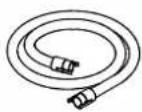 Suction hose Suction hose | 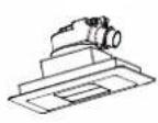 Decoration panel Decoration panel | 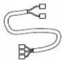 Wire harness Wire harness |
 Screws for duct flanges Screws for duct flanges |  Installation and operation manual Installation and operation manual |  Screws for bottom flange Screws for bottom flange | 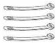 4 tie wraps 4 tie wraps |
Vasher for
aging bracket
4 pieces
Suction hose
Decoration panel
Wire harness
Screws for duct flanges
Installation and operation manual
Screws for bottom flange
4 tie wraps
Optional accessories
■ Refer to catalogues and technical literature for selecting an appropriate remote controller.
■ This option is not intended for bottom suction.
■ Only use accessories, optional equipment and spare parts made or approved by Daikin.
For the following items, take special care during construction and check after installation is finished
| Tick √ when checked | |
| Is the indoor unit fixed firmly?The unit may drop, vibrate or make noise. | |
| Is the wiring correct?The unit may malfunction or components may burn. | |
| Is nothing blocking the air outlet or inlet of either the indoor or outdoor units?It may result in insufficient cooling or heating. | |
| Are all accessories, cartons and tapes removed from inside of the unit?It may result in unit malfunction. |
Notes to the installer
Read this manual carefully to ensure correct installation. Be sure to instruct the customer how to properly operate the system and show him/her the enclosed operation manual.
Selecting installation site
(See figure 1 and figure 2)
1 Select an installation site where the following conditions are fulfilled and has meets your customer's approval.
- Where nothing blocks air flow.
- Where sufficient clearance for maintenance and service can be ensured.
- Where there is no risk of flammable gas leaking.
- The equipment is not intended for use in a potentially explosive atmosphere.
- When installing the wireless remote controller kit, the distance between wireless remote controller and indoor unit might be shorter if there are fluorescent lights, which are electrically started in the room. The option kit must be installed as far as possible away from fluorescent lights.
2 Ensure that a protective guard is installed on the air suction side.
The protection must comply with relevant European and national regulations.
3 Use suspension bolts for installation. Check whether the ceiling is strong enough to support the weight of the indoor unit and option kit. If there is a risk, ceiling must be reinforced before installing the unit.
1 Indoor unit
2 Auto-Cleaning option kit
3 Flange connection
4 Hangers
5 Switch box
Preparations before installation
■ Remove all accessories and accessible cartons (Refer to figure 3 - item 1.) from the inside of the unit.
For installation, choose one of the possibilities listed below.

text_image
Technical diagram of a heat exchanger or cooling unit with numbered components labeled 1, 2, and 3.1 Factory installed hangers
2 Front installation - temporarily remove protection net before installation.
3 Side installation
1 Factory installed hangers

text_image
Model A B BAE20A62 830 840 BAE20A82 1030 1040 BAE20A102 1230 1240 620 119 500 Suspension bolt pitch Air discharge Control box Air inlet B (Suspension bolt pitch) 1130 SERVICE SPACE Ceiling Arrow view A Inspection door (Ceiling opening) (units : mm)For a different way of installation, the factory set hangers should be repositioned by an authorized installer.
1 Remove 3 screws.
2 Change hanger position.
3 Put the 3 screws back. (2 screws in case of the side installation)
NOTE
Hanger on switch box side can not be changed.

■ Relation of the unit to the suspension bolt position.
- Install the inspection opening on the control box side where maintenance and inspection of the control box are easy. Install the inspection opening also in the lower part of the unit.
■ Make sure that there is easy access to the filter from a bottom side.
■ Install the suspension bolts.
- (Use W3/8 to M10 suspension bolts.)
Use a hole-in-anchor, sunken insert, sunken anchor, for existing ceilings, and a sunken insert, sunken anchor or other part to be processed in the field to reinforce the ceiling to bearing the weight of the unit. (Refer to figure 4.)
1 Anchor
2 Ceiling slab
3 Long nut or turn-buckle
4 Suspension bolt
5 Auto-Cleaning option kit
■ All above parts are field supplied.
Suspension bolt installation
To determine proper bolt position use the carton delivered with the unit.
1 Cut the carton according to the printed instructions.

natural_image
Pure diagram of scissors cutting through a rectangular frame with vertical bars and diagonal lines (no text or symbols)2 Place the cut part of the carton next to the already installed duct unit. Position edge of carton according to the dotted parallel line.
3 Position triangles printed on the carton according to the edge of casing (dotted lines).

natural_image
Pure electrical circuit lines without any symbols4 Mark position of holes for suspension bolts.
Auto-Cleaning option kit installation
1 Remove a flange from the option and install it to the indoor unit suction side.

natural_image
Architectural floor plan showing room layout and interior components (no text or labels)- For the flange use the screws from the accessory bag (screws with hexagon head).
- Second flange must stay on the option kit.
2 Permanently remove 4 screws holding both trolleys. (Screws are used only for transportation purpose.)

natural_image
Technical line drawing of an industrial cooling unit with fan and cooling elements (no text or symbols)1 Protection net
3 Remove the carton from under both trolleys. (Refer to figure 3 - item 1.)
4 Install the option kit temporarily.
- Move the option kit to the indoor unit from the bottom side in order to fix the flanges together. - Attach the hanger bracket to the suspension bolt. Be sure to fix it securely by using a nut and washer from the upper and lower sides of the hanger bracket. (See figure 5)
1 Nut (field supply) 2 Washer for hanger bracket (accessories) 3 Tighten (double nut)
5 Check if the unit is leveled horizontally.
6 Tighten the upper nut.
7 Screw both flanges together from sides and bottom side. Use screws with rounded head (accessories). (Refer to figure 6.)
8 Connect the Auto-Cleaning option kit with indoor unit using a wire harness (accessories) according to figure 7 and according to chapter "Electric wiring work".
9 Turn ON the indoor unit power supply to let the trolleys perform initialization and move into parking position (wait until the trolleys move to switch box side = parking position).
10 Temporarily remove the protection net by loosening all screws (number of screws differs by casing size) on the lower side.
11 Remove cartons originally covered behind both trolleys - opposite side from switch box. (Refer to figure 3 - item 2.)
12 Insert the air filter according to chapter "Manual cleaning of filter"
- Remove fixing plate of the filter and insert the air filter into the unit. - Fabric strips attached to the filter shall be from bottom side. - Install the fixing plate back.
13 Reinstall the protection net.
Perform Auto Cleaning test operation according to chapter "Test operation"

NOTE
Filter cannot be inserted inside the unit unless the trolleys are in parking position.
Decoration panel installation
See figure 8
1 Decoration panel
2 Connection port on decoration panel
3 Connection port on the Auto-Cleaning option kit
4 Hose
5 Spring
1 Attach the hose from the accessory set to the connection port on the Auto-Cleaning option kit. Second end of the hose shall be attached to the decoration panel assembly.
2 Select proper position in the ceiling for the decoration panel considering length of the hose.
3 Make a hole in the false ceiling. (Length 104×183 mm)
4 Disconnect the hose from the decoration panel.
5 Fix the decoration panel to the ceiling by springs.
6 Attach hose back to decoration panel port.
Electric wiring work
General instructions
All field wiring and components must be installed by a licensed electrician and must comply with relevant European and national regulations.
■ Follow the "Wiring diagram" attached to the unit body to wire the indoor unit and Auto-Cleaning option kit.
■ All cables entering the unit should be fixed by tie wraps (accessory).
If the supply cord is damaged, it must be replaced by the manufacturer, its service agent or similarly qualified persons in order to avoid a hazard.
How to connect wiring
Remove the switch box covers as shown in figure 7, and connect the indoor unit and option unit with wire harness (accessory set)
1 Switch box cover
2 Switch box low voltage wiring inlet
3 Switch box high voltage wiring inlet
4 Wiring diagram of the option kit
5 Switch box of the option kit
6 Wire harness (accessory set)
7 Fixing point
■ Plug all connectors according to figure 7.
■ Make sure that all connectors are securely connected.
It is necessary to fix the wire harness by the tie wraps (accessory set) Use the fixing point shown in the figure 7.
■ When attaching the switch box cover make sure not to pinch any wires.
■ Make sure that all wiring entering the units has this shape, which prevents water flowing inside.

natural_image
Two abstract geometric shapes with checkmark indicators, no text or symbols present■ After all wiring connections are done, fill in any gaps in the casing wiring holes with putty or insulation material (field supply) thus to prevent small animals or dirt from entering the unit from outside and causing short circuits in the control box.
NOTE

In case of combination of Auto-Cleaning option kit with indoor unit FXDQ-A2/P2 contact your Daikin dealer to obtain BAE20WH wire harness for successful connection between indoor unit and Auto-Cleaning option kit.
TEST OPERATION
Perform the test operation of the Auto-Cleaning option kit after the test operation of the indoor unit is finished.
The test operation of the Auto-Cleaning option kit is not possible while the indoor unit is in operation.
■ Check that the Switch box lids of the indoor unit, outdoor unit, and Auto-Cleaning option kit, respectively, are closed
■ Turn the indoor unit power on
The Auto-Cleaning option kit will perform the initialization (in case of trolleys are not in parking position) it may take up to 5 minutes.
■ Conduct the Auto-Cleaning test operation
- Confirm the cleaning operation of the filter with the remote controller.
Test operation method with remote controller
1 Stop the operation of the indoor unit.
2 Press and hold the Cancel button for at least 4 seconds while the backlight is lit. The service settings menu will appear.
3 Select Test Filter Auto Clean from the service settings menu, and press the Menu/Enter button.
4 " will appear on the basic screen.
The display will disappear when the test operation is finished. The required test operation time is approximately 5-10 minutes (depending on casing size).
1 2

text_image
Cool Set to Cool 28°C
Press and hold Cancel button for 4 seconds or longer during backlight lit.
3

text_image
Service Settings 2/3 Indoor Unit Status Outdoor Unit Status Forced Fan ON Switch Main Sub Controller Filter Indicator OFF Test Filler Auto Clean Return Setting
Press Menu/Enter button.
4

text_image
Cool Set to Cool 28°C Collect dustBacklight for LCD
Press any button and the backlight will be lit for approximately 30 seconds.
Test items on test operation
| Tick √when checked | Test items |
| Are both trolleys moving? | |
| Is there no abnormal sound? | |
| Are both trolleys going simultaneously? | |
| Do both trolleys go to the end of the casing? | |
| Did both trolleys return to the starting position? |
MAINTENANCE
Maintenance frequency of the Auto-Cleaning option kit is 1 year.

Caution
■ Following items shall be done during maintenance.
■ Only a qualified service person is allowed to perform maintenance.
■ Before obtaining access to terminal devices, all power supply circuits must be interrupted.
Manual cleaning of the filter
If the dirt becomes impossible to clean, change the air filter. (Air filter for replacement is a spare part.)
1 Remove one screw and slide the fixing plate to the side where a switch box is located.

text_image
Technical diagram of a mechanical or electrical component with labeled parts and directional arrows indicating flow or movement.1 Fixing plate
2 Remove the air filter.
3 Clean the air filter.
Use vacuum cleaner (A) or wash the air filter with water (B).
(A) Using a vacuum cleaner

(B) Washing with water

When the air filter is very dirty, use soft brush and neutral detergent.
Remove water and dry in the shade.
4 Insert the clean filter back, secure it by the fixing plate and put the screw back.
Cleaning of the interior
1 Remove protection net.
2 Clean interior of the casing by vacuum cleaner or wet cloth.
3 Perform a test operation.
4 Use vacuum cleaner to remove remaining dirt from the dust box. When trolley is moving, press vacuum cleaner hose to the outlet of the dust box at least for 30 seconds.

natural_image
Technical line drawing of a mechanical device with labeled components (no text or symbols present)1 Brush unit with dust box
2 Vacuum cleaner hose
| Unified Wiring Diagram Legend | |||||
| For applied parts and numbering refer to the wiring diagram sticker supplied on the unit. Part numbering is realized by Arabic numbers in ascending order for each part and is represented in the overview below by symbol "" in the part code. | |||||
 | : CIRCUCBREEMEROTECTIVE EARTH | 1 | |||
 | : CONNECTION : PROTECTIVE EARTH (SCREW) | [7H02] | |||
| [XS6C] | : CONNECTOR | [6S4T] | : RECTIFIER | ||
 | : EARTH : RELAY CONNECTOR | [8H7Z] | |||
 | : FIELD WIRING : SHORT CIRCUIT CONNECTOR | [WASZ] | |||
| [BY4W] | : FUSE : TERMINAL | [4Y0X] | |||
| [SW43] | : INDOOR UNIT : TERMINAL STRIP | [06Y3] | |||
| INDOOR | |||||
| [XC16] | : OUTDOOR UNIT : WIRE CLAMP | [Z5SX] | |||
| [2GAC] | |||||
| BLK : BLACK | GRN : GREEN | PNK : PINK | WHT : WHITE | ||
| BLU : BLUE | GRY : GREY | PRP, PPL : PURPLE | YLW : YELLOW | ||
| BRN : BROWN | ORG : ORANGE | RED : RED | |||
| A*P | : PRINTED CIRCUIT BOARD | PS | : SWITCHING POWER SUPPLY | ||
| BS* | : PUSH BUTTON ON / OFF, OPERATION SWITCH | PTC* | : THERMISTOR PTC | ||
| BZ, H*O | : BUZZER | Q* | : INSULATED GATE BIPOLAR TRANSISTOR (IGBT) | ||
| C* | : CAPACITOR | Q'DI | : EARTH LEAK CIRCUIT BREAKER | ||
| AC*, CN*, E*, HA*, HE, HL*, HN*, HR*, MR*, A, MR*, B, S*, U, V, W, X*A | : CONNECTION, CONNECTOR | Q*L | : OVERLOAD PROTECTOR | ||
| D*, V*D | : DIODE | Q*M | : THERMO SWITCH | ||
| DB* | : DIODE BRIDGE | R* | : RESISTOR | ||
| DS* | : DIP SWITCH | R*T | : THERMISTOR | ||
| E*H | : HEATER | RC | : RECEIVER | ||
| F*U, FU*(FOR CHARACTERISTICSREFER TO PCB INSIDE YOUR UNIT) | : | FUSE | S*C | : | |
| FG* | : CONNECTOR (FRAME GROUND) | S*L | : FLOAT SWITCH | ||
| H* | : HARNESS | S*NPH | : PRESSURE SENSOR (HIGH) | ||
| H*P, LED*, V*L | : PILOT LAMP, LIGHT EMITTING DIODE | S*NPL | : PRESSURE SENSOR (LOW) | ||
| HAP | : LIGHT EMITTING DIODE (SERVICE MONITOR GREEN) | S*PH, HPS* | : PRESSURE SWITCH (HIGH) | ||
| HIGH VOLTAGE | : HIGH VOLTAGE | S*PL | : PRESSURE SWITCH (LOW) | ||
| IES | : INTELLIGENT EYE SENSOR | S*T | : THERMOSTAT | ||
| IPM* | : INTELLIGENT POWER MODULE | S*W, SW* | : OPERATION SWITCH | ||
| K*R, KCR, KFR, KHUR | : MAGNETIC RELAY | SA* | : SURGE ARRESTOR | ||
| L | : LIVE | SR*, WLU | : SIGNAL RECEIVER | ||
| L* | : COIL | SS* | : SELECTOR SWITCH | ||
| L*R | : REACTOR | SHEET METAL | : TERMINAL STRIP FIXED PLATE | ||
| M* | : STEPPER MOTOR | T*R | : TRANSFORMER | ||
| M*C | : COMPRESSOR MOTOR | TC, TRC | : TRANSMITTER | ||
| M*F | : FAN MOTOR | V*, R*V | : VARISTOR | ||
| M*P | : DRAIN PUMP MOTOR | V*R | : DIODE BRIDGE | ||
| M*S | : SWING MOTOR | WRC | : WIRELESS REMOTE CONTROLLER | ||
| MR*, MRCW*, MRM*, MRN* | : MAGNETIC RELAY | X* | : TERMINAL | ||
| N | : NEUTRAL | X*M | : TERMINAL STRIP (BLOCK) | ||
| n = * | : NUMBER OF PASSES THROUGH FERRITE CORE | Y*E | : ELECTRONIC EXPANSION VALVE COIL | ||
| PAM | : PULSE-AMPLITUDE MODULATION | Y*R, Y*S | : REVERSING SOLENOID VALVE COIL | ||
| PCB* | : PRINTED CIRCU IT BOARD | Z*C | : FERRITE CORE | ||
| PM* | : POWER MODULE | ZF, Z*F | : NOISE FILTER | ||
FOR THE USER
NAMES AND FUNCTIONS

text_image
Technical diagram of an industrial device with numbered components and airflow indicators1 Filter
2 Cylinder unit
3 Brush unit with a dust box
4 Hose
5 Decoration panel
6 Switch box
7 Suction
8 Outlet
■ The illustration shows the Auto-Cleaning option kit with transparent top plate.
Functions other than basic operation items (i.e., ON/OFF, Operation mode selector, Fans speed control, and temperature settings) are set from the menu screen.
NOTE

Do not install the remote controller where it can be directly exposed to sunlight. This may result in discoloration or failure of the display.
■ Do not pull or twist the remote controller cord. Otherwise, the remote controller may error.
■ Do not press the buttons on the remote controllers with sharp objects. This may result in damage or faulty indications.
Indicator

text_image
DAIKIN 1 11 4 5 6 7 9 8 3 10 21 Operation mode selector button
- Press this button to select the operation mode of your preference. (Available modes vary with the connecting model.)
2 Fan speed button
- Used to indicate the Air Volume setting screen. (Available fan speed vary with the connection model.) For details, refer to operation manual of the controller.
3 Menu/Enter button
- Used to indicate the main menu. - Used to enter the setting item selected.
4 Up button ▲
- Used to raise the set temperature. - The next items on the upper side will highlight. The highlighted items will scroll continuously when the button is kept pressed.) - Used to change the item selected.
5 Down button ▼
- Used to lower the set temperature. - The next items on the lower side will be highlighted. (The highlighted items will scroll continuously when the button is kept pressed.) - Used to change the item selected.
6 Right button
- Used to highlight the next items on the right-hand side. - Each screen scrolls in the right-hand direction. - Home leave settings are enabled with this button kept pressed for at least four seconds.
7 Left button
- Used to highlight the next items on the left-hand side.
- Each screen scrolls in the left-hand direction.
- Home leave settings is enabled with this button kept pressed for at least four seconds.
8 ON/OFF button
- Press this button and system will start. - Press this button again and system will stop.
9 Operation lamp (green)
- This lamp lights up during operation. - This lamp blinks if an error occurs.
10 Cancel button
- Used to return to the previous screen.
11 LCD (with backlight)
- The backlight will be light for approximately 30 seconds by pressing any operation button.
Operate buttons excluding the ON/OFF button while the backlight is lit. - If two remote controllers are used to control a single indoor unit, the backlight of the remote controller operated earlier than the other one will be lit. (The backlights of the two remote controllers will not be lit simultaneously.)
Liquid crystal display
There are two display types, i.e., standard and detailed displays. The standard display is by default set.
■ To go to the detailed display, select the detailed display in the main menu.
For details, refer to the operation manual provided with the wired remote controller.
■ Each of the following screens explains the state of the LCD display regarding filter auto cleaning function.
For the contents of the LCD displays while the product is not in filter auto cleaning operation, refer to the operation manual provided with the wired remote controller.
Standard display Detailed display

text_image
Auto Set to Cool 28°C Heat 20°C- "Cleaning" display

text_image
Auto Fri 11:03 Setback Cool 28°C Heat 20°C Room 20°C- "Cleaning" display
1 "Cleaning" display
A Displayed while the product is performing filter auto cleaning.
Collect dust from dust box. (See page 10.)
2 Message
The following message will appear:
"Error: Push Menu Button."
"Warning: Push Menu Button."
- Displayed if the error or warning is detected. (See page 13.)
"Set clock from menu"
- Displayed to inform that the clock needs setting. (See page 9.)
- The product will not start filter auto cleaning at the designated period unless settings are made.
FILTER AUTO CLEANING SETTING
This product performs filter auto cleaning once a week as factory default setting.
Auto cleaning is performed in case the unit is not operating and specified time is reached. Only as a protection the cleaning function may force the unit to stop an operation and perform a cleaning cycle.
For example if an air-conditioner is running a certain amount of time after sign clean dust box appears.
NOTE

■ The correct clock settings are necessary.
The product will perform filter auto cleaning from 12:00 to 15:00 (as factory default) if the period for filter auto cleaning is not specified.
The product will perform filter auto cleaning at non-prescribed time if clock settings are not made.
Method of specifying start time
Operation method
1

text_image
Main Menu 1/2 Quick Start Ventilation Energy Saving Options Schedule Filter Auto Clean Maintenance Information Return Setting
■ Display the main menu screen.
■ Press ▼ to select the Filter Auto Clean on the main menu screen and press Menu/Enter button.

text_image
Filter Auto Clean Clock setting is not carried out. Do you want to set? Yes No Return Setting

text_image
Date & Time Year 011 Month 01 Day 01 Thursday 12:00 Return Setting2
If the clock has not been set, a screen like the one on the left will appear.
Press ◀▶ buttons to select Yes and press Menu/Enter button.
Set the current year, month, day, and time. (See "Clock&Calendar" on page 9.)
* Clock setting are required to set the start time of filter auto cleaning.

text_image
Filter Auto Clean Filter Auto Clean 0:00-3:00 Return Setting
3
■ The period will change whenever ▼▲ buttons are pressed in the Clock setting screen for filter auto cleaning.

text_image
00:00-03:00 03:00-06:00 06:00-09:00 09:00-12:00 12:00-15:00 15:00-18:00 18:00-21:00 21:00-00:00 Select the desired period from the ones displayed.■ Press Menu/Enter button. The setting confirmation screen will appear.
4

text_image
Filter Auto Clean Save the settings? Yes No Return Setting
■ Press ◀ button to select Yes on the settings confirmation screen. Press Menu/Enter button to set the filter auto clean and return to the basic screen.
NOTE
The filter auto clean function takes around 5-10 minutes. Depending on casing size. In case of a high dust environment the cleaning cycle takes 10\~20 minutes.
Execution of the cleaning function, always during the scheduled time slot of 3 hours, will start as soon as possible considering the following conditions:
- during the first hour the cleaning function will only be performed if the unit is not operating;
- during the second and third hour same condition as during first hour or when the unit is in thermostat OFF.
The unit will try to perform the cleaning function during the next scheduled time slot of 3 hours in case it was not executed.
If the unit, in case of VRV, could not perform the cleaning function after elapse of 2 consecutive scheduled time slots of 3 hours, error code AH09 displays on the remote controller (see "NOTE" on page 8). The error code remains displayed as long as the function is not completed, but the unit can operate normally at all times.
Sky air units do not display that error code.
Filter auto cleaning
The product has the following three operation modes, any one of which can be set for filter auto cleaning.
| Operation mode | Description | Clock setting | Availability for designating time to start filter auto cleaning |
| Scheduled timer operation | Performs filter auto cleaning during the designated period selected from 8 periods. | √ | √ |
| 12:00 to 15:00 operation | Performs filter auto cleaning during the factory-set period of time (12:00 to 15:00). | √ | ✕ |
| Auto control operation | Performs filter auto cleaning according to the control reference. | ✕ | ✕ or √ |
Preparation
■ To designate a period for filter auto cleaning, avoid selecting the periods of time when the product is in air conditioning operation as much as possible.
If the period for filter auto cleaning overlaps with that for the air conditioning operation of the product, the product may stop air conditioning forcibly and start filter auto cleaning.
If the message "Set clock from menu" appears, make clock settings again so that the filter auto cleaning will be performed during the designated period.
NOTE

The product will be set to auto control operation mode unless clock settings are made again if the clock is reset for some reason (e.g., no power is supplied to the product for 48 hours or longer).
■ The product may generate a little noise while the dust is scraped with the brush.
CLOCK&CALENDAR
Setting the clock
Operation method
1

text_image
Cool Set to Cool 28°CBasic screen

■ Press Menu/Enter button.
2

text_image
Main Menu 1/2 Quick Start Ventilation Energy Saving Options Schedule Filter Auto Clean Maintenance Information Return SettingMain menu screen
3
■ The main menu screen will appear.

text_image
Main Menu 2/2 Configuration Current Settings Clock & Calendar Language Return Setting

■ Press ▼▲ to select Clock & Calendar on the main menu screen.
Press Menu/Enter button to display the clock setting screen.
4

text_image
Date & Time Year 2011 Month 01 Day 01 Thursday 12:00 Return Setting

■ Select "Year" with ◀▶ buttons.
Input the year with ▼▲ buttons.
Holding down the button causes the number to change continuously.
5

text_image
Date & Time Year 2011 Month 10 Day 01 Thursday 12:00 Return Setting

■ Select "Month" with buttons.
Input the day with ▼▲buttons.
Holding down the button causes the number to change continuously.
6

text_image
Date & Time Year 2011 Month 10 Day Thursday 12:00 Return Setting

■ Select "Day" with ◀▶ buttons.
Input the day with ▼▲ buttons.
Holding down the button causes the number to change continuously.
Days of the week change automatically.
7

text_image
Date & Time Year 2011 Month 10 Day 07 Thursday 12 00 Return Setting

■ Select "Hour" with ◀▶ buttons.
Input the hour with ▼▲ buttons.
Holding down the button causes the number to change continuously.
8

text_image
Date & Time Year 2011 Month 10 Day 07 Thursday 12:21 Return Setting


■ Select "Minute" with ◀▶ buttons.
Input the minute with ▼▲ buttons.
Holding down the button causes the number to change continuously.
■ Press Menu/Enter button.
The settings confirmation screen will appear.
9

text_image
Date & Time Save the settings? Yes No Return Setting

■ Press ◀ button to select Yes on the settings confirmation screen.
Press Menu/Enter button to set the clock and return to the basic screen.
While making filter auto cleaning settings, the display will return to the screen for designating a period for filter auto clean. (See page 8.)
CURRENT SETTING
Adjusting the current settings
Operation method

text_image
Main Menu 2/2 Configuration Current Settings Clock & Calendar Language Return Setting
1
■ Display the main menu screen. (See page 8.)
■ Press ▼▲ buttons to select Current Settings on the main menu screen and press Menu/Enter button.

text_image
Current Settings Ventilation rate Low Ventilation mode Auto Schedule Disable Display Mode Standard Display Item Outside Filler auto clean 00-03 Return
2
A list showing the current setting status will appear.
Press ◀▶ buttons to go to the next item.
- Pressing Cancel button takes you back to the main menu screen.
Display items may differ depending on the model.
Only the items that can be set are displayed.
Refer to the displayed "Filter auto clean" settings for the present set condition of filter auto cleaning.
Example: A period from 12:00 to 15:00 is set for filter auto cleaning.
Filter auto clean 12-15
Sign for collecting dust from the dust box will appear when the time comes.
Promptly collect the dust when the sign is confirmed.
* The dust collection sign will appear after 1 month (factory setting). The intervals can be selected shorter if the product is used in place with excessive dust. Intervals can be set to: no indication, 672h, 168 and 24h.
NOTE

■ Contact your Daikin installer to change the factory set appearance interval of dust collection sign.
| Place of display | Collection sign 1 | Collection sign 2 | Collection sign 3 | |
| Remote controller | LCD | Signappears | Signappears | "AH-05"(error sign)will appear |
| Operation lamp | Lights Blinking | Blinking | ||
NOTE

Collect the dust in the box when appears. If the dust will not be removed, the unit may malfunction.
DUST COLLECTION WITH VACUUM CLEANER
1 Vacuum the dust in the dust box on completion of confirming the dust collection sign.
NOTE

■ Dust collection with a vacuum cleaner is not possible during filter auto cleaning. Make sure that " [IMAGE] is not displayed on the remote controller screen before dust collection.
2 Connect the provided connection pipe and attachment to match the vacuum cleaner pipe.
Insert the connection pipe and attachment into the vacuum cleaner pipe.
NOTE

The connection pipe can be purchased separately as option BAEVACEP. It is not delivered together with the Auto-Cleaning option kit.


text_image
2 3 5 41 Vacuum cleaner pipe with an inner diameter of 32 to 38 mm in diameter
2 Vacuum cleaner pipe with an inner diameter of 38 to 42 mm in diameter
3 Vacuum cleaner pipe
4 Connection pipe
5 Attachment
When storing the connection pipe, use the provided hook-and-loop fastener strip and take the following procedure.

text_image
Technical diagram of a mechanical assembly with numbered components and directional arrows indicating movement or force.1 Example 1
2 Example 2
3 Connection pipe
4 Vacuum cleaner hose or pipe
5 Flat surface in the place of storage
6 Hook-and-loop fastener strips
Example 1
1 Peel the release paper off the double-stick tape on the back of the fastener strip, and paste the fastener strip onto a flat surface in the place of storage.
2 Press the fastener strip of the connection pipe onto the fastener strip pasted in step 1.
Example 2
Wind the hook-and-loop fasteners on the connection pipe around a vacuum cleaner hose or pipe to store the connection pipe.
NOTE

The attachment cannot be connected to a vacuum cleaner pipe without a round-shaped leading end (e.g., a stand-type or handheld-type vacuum cleaner) or a pipe that has a hole midway to cause air leakage. Consult your Daikin dealer if the attachment cannot be connected to your vacuum cleaner.
■ Use a vacuum cleaner with a minimum sucking work rate of 300 W.
■ Do not use a vacuum cleaner full of dust and low in suction power.
* The use of the above vacuum cleaner may result in a dust collection failure.
3 Insert the leading end of the connection pipe into the dust collection inlet of the suction grille from right under. Then press fit the leading end onto internal air inlet until the leading end snaps.

text_image
Technical diagram showing a mechanical assembly with labeled parts 1, 2, 3, and 4, including a directional arrow indicating movement.1 Dust collection inlet
2 Air inlet
3 Connection pipe
4 Rises approximately 10mm
4 While the leading end of the connection pipe closely come in contact, turn on the vacuum cleaner with the suction power set to maximum and vacuum the dust for at least 10 seconds.
While vacuuming the dust take away the hose and put it back several times.
Resetting dust collection sign
Operation method
1

text_image
Auto Set to Cool 28°C Heat 20°C Collect dust
When the time for collecting dust from the dust box comes, collection sign "Will appear alternately on the lower part of the basic screen.
At the time of this state, press the Menu/Enter button on the basic screen.

text_image
Dust Collection Method Was dust collected? Yes No Return Setting

2

text_image
Cool Set to Cool 28°C■ After vacuuming the dust in the dust box, press buttons on the collection confirmation screen and select Yes
■ Press the Menu/Enter button to reset the dust collection sign.
TROUBLESHOOTING
The following symptoms are not signs of malfunctions.
| Symptom Probable cause | ||
| Slight clicking noise is generated. | The "is" displayed or the indicator on the panel is flashing green (*). | The driving sound of trolleys. |
| Scorching noise is generated. | The driving sound of the brush. | |
| The air conditioning operation of the product stops temporarily. | The dust box is full, and filter auto cleaning is unavailable. | |
* The factory setting will not allow the indicator to flash green.
Check before requesting servicing.
| Symptom Probable cause Remedy | ||
| Dust sticks to the air filter (dust falls). | The room has a large quantity of dust temporarily as a result of the cleaning of the room. | Stop the operation of the air conditioner until the cleaning of the room is finished. If necessary, clean the air filter. |
| The dust box is full. | Vacuum the dust. (See page 11.) | |
| The display "AH" will appear on screen of the remote controller and the operation lamp will flash. | The dust box is full. | Vacuum the dust and confirm it on the remote controller. (See page 12.) |
| The dust collection sign appears soon after the dust is vacuumed. | Check the dust box cleaning interval. | Set preferred timing. |
| The product does not run according to the timer settings. | Are the settings in the remote controller wrong? | Make settings in the remote controller again. |
| Symptom Probable cause Remedy | ||
| The error code AH-14 will appear on screen of the remote controller. | One or both trolleys did not arrive from one to other side in time limit of 300 seconds. | Check if 4 screws holding the trolleys and carton from under and behind the trolleys are removed.Stop cleaning operation, turn the indoor unit power off, wait 10 seconds. Turn indoor unit power on and check whether there aren't any objects blocking the trolley to reach the limit switch. |
If the product is still not in good condition after checking the above, contact your Daikin dealer. The customer must not attempt to repair the product.
Contact your Daikin in the following cases

■ When the air conditioner is malfunctioning (e.g., giving off a burning odor), stop the air conditioner and turn off power.
Continued operation under such circumstances may result in failure, electric shocks, or fire.
| Symptom | Measures to be taken before requesting servicing |
| The fuse blows out or safety devices, such as the power circuit breaker and earth leakage circuit breaker trip often. | Do not turn ON the product. |
| The operation of the buttons on the remote controller is inaccurate. | Turn OFF the product. |
| There are other malfunctions or faults. | Stop operation of the product. |
Either one of the following messages flashes on the basic screen of the remote controller."Error: Push Menu Button."* The operation indicator will blink."Warning: Push Menu Button."* The operation indicator will not blink. | Check the malfunction codes. (see below) |
Error code display
Operation method

text_image
Cool Set to Cool 28°C Error: Press Menu Button
1
If an error occurs, either one of the following items will blink in the basic screen.
"Error: Push Menu Button."
* The operation indicator will blink.
"Warning: Push Menu Button."
* The operation indicator will not blink.

Press Menu/Enter button.
2

text_image
Error code:A1 Contact Info 0123-4567-8900 Indoor Model —/000 Outdoor Model —/000 Return■ The error code blinks and the contact address and model name will appear.
■ Notify your Daikin dealer of the Error code and Model name.
AFTER-SALE SERVICE

■ Do not disassemble, modify, or repair the unit.
Doing so may result in electric shocks or fire.
Contact your Daikin dealer.
■ Do not relocate or reinstall by yourself.
Improper installation may result in electric shocks or fire.
Contact your Daikin dealer.
■ Beware of fire in case of refrigerant leakage.
If the air conditioner is not operating correctly, i.e. not generating cool or warm air, refrigerant leakage could be the cause. Contact your Daikin dealer for assistance. The refrigerant within the air conditioner is safe and normally does not leak. However, in the event of a leakage, contact with a naked burner, heater or cooker may result in generation of noxious gas. Do not use the air conditioner any longer until a qualified service person confirms that the leakage has been repaired.
Advise the repairer of the following items
Model name
Date of installation
- Failure conditions: As precise as possible.
- Your address, name, and telephone number
Stock Period of Performance Spare Parts
Performance spare parts are components that are required to maintain the function of the product.
Daikin has a stock of performance spare parts for the air conditioner for nine years after the stoppage of producing the air conditioner.
Rough Standards for Part Maintenance Frequency
| Main part name | Inspection period |
| Filter 1year |
NOTE

This table shows main parts. For details, refer to the maintenance inspection contract.
The replacement frequency depends on condition of the filter during yearly maintenance. If the dust become impossible to clean, replace the filter.
■ Regular inspection is required, depending on the installation environment.
For details, contact your Daikin dealer. Furthermore, the overhauling or internal cleaning of the product conducted by repairers other than those authorized by Daikin may not be within the scope of Daikin's product warranty term.
Inquiry
Contact your Daikin dealer for after-sale services.
DISPOSAL REQUIREMENTS

For batteries, a chemical symbol can be printed beneath the symbol. This chemical symbol means that the battery contains a heavy metal above a certain concentration. Possible chemical symbols are:
■Pb: lead (>0.004%)
Do not try to dismantle the system yourself: the dismantling of the product, treatment of the refrigerant, of oil and of other parts must be done by a qualified installer in accordance with relevant local and national legislation.
Units and waste batteries must be treated at a specialized treatment facility for re-use, recycling and recovery.
By ensuring correct disposal, you will help to prevent potential negative consequences for the environment and human health.
Please contact the installer or local authority for more information.
DAIKIN INDUSTRIES CZECH REPUBLIC s.r.o.
U Nové Hospody 1/1155, 301 00 Plzeň Skvrňany, Czech Republic
DAIKIN EUROPE N.V.