52C432XANR - Security Camera Dahua Technology - Free user manual and instructions
Find the device manual for free 52C432XANR Dahua Technology in PDF.

User questions about 52C432XANR Dahua Technology
0 question about this device. Answer the ones you know or ask your own.
Ask a new question about this device
Download the instructions for your Security Camera in PDF format for free! Find your manual 52C432XANR - Dahua Technology and take your electronic device back in hand. On this page are published all the documents necessary for the use of your device. 52C432XANR by Dahua Technology.
USER MANUAL 52C432XANR Dahua Technology
Intelligent Speed Dome Installation Manual
Version 1.0.3
Table of Contents
1 INSTALLATION PREPARATION.... 1
1.1 Basic Requirements....1
1.2 Installation Check....1
1.3 Cable Preparation....1
1.3.1 Cable Lowest Specification Requirement....1
1.3.2 Select Needed Power Supply Cable According to Transmission Distance....2
2 SPEED DOME INSTALLATION....3
2.1 Check Accessories....3
2.2 Open Device....3
2.3 DIP Switch Setup .... 3
2.3.1 DIP Switch Location and Function....3
2.3.1.1 Analog Speed Dome 4
2.3.1.2 HDCVI Speed Dome 4
2.3.2 DIP Switch Setup 5
2.3.3 Address Setup....5
2.3.4 Baud Rate and Parity Setup....6
2.3.4.1 Analog Speed Dome 6
2.3.4.2 HDCVI Speed Dome 6
2.4 Terminal Matching Resistance Setup....7
2.5 Reset Button Location and SD Card Installation (Network Speed Dome)......8
2.6 Speed Dome Cable 9
2.6.1 Cable Description....9
2.6.2 Cable Connection....10
2.6.3 Alarm Cable Connection....10
2.6.4 Connect Speed Dome GND Cable....11
3 IN-CEILING MOUNT 12
3.1 Mounting Component and Dimension....12
3.2 Wall-mounted Bracket Installation Steps 12
3.2.1 Installation Conditions....12
3.2.2 Installation Steps....12
4 APPENDIX I THUNDER PROOF AND SURGE PROTECTION (OUTDOORS)
17
4.1 Lightning Protection (Indoors)....17
5 APPENDIX II ABOUT RS485 BUS....19
5.1 RS485 Bus Main Feature....19
5.2 RS485 Bus Transmission Distance....19
5.3 The Problem in Practical Use....19
5.4 RS485 Bus FAQ....20
6 APPENDIX III THE 24V AC WIRE GAUGE AND TRANSMISSION DISTANCE RELATIONSHIP SHEET ...... 21
7 APPENDIX IV12V DC WIRE GAUGE AND TRANSMISSION DISTANCE RELATIONSHIP SHEET 23
8 APPENDIX V WIRE GAUGE REFERENCE SHEET 24
Welcome
Thank you for purchasing our speed dome!
Please read the following safeguards and warnings carefully before you install or use the product!
Important Safeguards and Warnings
1. Qualified Engineer Needed
- The installation engineer or maintenance engineer shall have corresponding CCTV system installation certificate or maintenance qualification certificate.
- The installation engineer or maintenance engineer shall have qualification certificate for work at height.
- The installation engineer or maintenance engineer shall have the basic knowledge and operation technique for low-voltage cable layout and low-voltage electronic cable connection.
- Please read the installation manual carefully and keep it well for future reference,
We are not liable for any problems caused by unauthorized modifications or attempted repair.
2. Lifting Appliance Requirement
- Please select the proper speed dome installation mode and use the lifting appliances at the safety environment.
● The lifting appliances shall have the enough capacity to reach the installation height.
● The lifting appliances shall have safe performance.
The precaution measures include two types: Warning and Note.
● Warning: It is to alert you there is an optional risk of death or series injury!
● Note: It is to alert you there is an optional risk of damage or property loss!
Warning
- All installation and operation here should conform to your local electrical safety codes. We assume no liability or responsibility for all the fires or electrical shock caused by improper handling or installation.
- Be sure to use all the accessories (such as power adapter) recommended by manufacturer.
- Do not connect several speed domes to one power adapter. It may result in overheat or fire if it exceeds the rated load.
- Before you connect the cable, install or uninstall, or begin the daily maintenance work, please turn off the power and unplug the power cable.
- Please make sure the produce is secure firmly on the wall or the ceiling.
-
Please turn off the power and unplug the power cable, If there is any smoke, disgusting smell, or noise. Please contact your local retailer or customer service centre for help.
-
All the examination and repair work should be done by the qualified service engineers. We are not liable for any problems caused by unauthorized modifications or attempted repair.
Note
1. Safety Transportation
- Heavy stress, violent vibration or water splash are not allowed during transportation, storage and installation.
● This series product must use split type package during the transportation. - We are not liable for any damage or problem resulting from the integrated package during the transportation.
2. When device is malfunction
Shut down the device and disconnect the power cable immediately if there is smoke, abnormal smell or abnormal function. Please contact your local retailer ASAP.
3. Do not try to dismantle or modify the device
● There is risk of personal injury or device damage resulting from opening the shell.
- Please contact your local retailer if there is internal setup or maintenance requirement.
We are not liable for any problems caused by unauthorized modifications or attempted repair.
4. Do not allow other object falling into the device
- Please make sure there is no metal or inflammable, explosive substance in the speed dome.
● The above mentioned objects in the device may result in fire, short-circuit or damage. - Please shut down the device and disconnect the power cable if there is water or liquid falling into the camera. Please contact your local retailer ASAP.
- Please pay attention to the camera. Avoid the sea water or rain to erode the camera.
5. Handle carefully
Do not allow this series product fall down to the ground. Avoid heavy vibration.
6. Installation Environment Requirement
- This series speed dome should be installed in a cool, dry place away from direct sunlight, inflammable, explosive substances and etc.
- This series product shall be away from the strong electromagnetism radiant, please keep it away from wireless power, TV transmitter, transformer and etc.
7. Daily Maintenance
- Please use the soft cloth to clean dust on the shell, or you can use soft cloth with cleaning liquid to clean the shell and then use soft cloth to make it dry.
- Do not use gasoline, dope thinner or other chemical material to clean the shell. It may result in shell transfiguration or paint flake.
- Do not allow the plastic or rubber material to touch the shell for a long time. It may result in paint flake.
1 INSTALLATION PREPARATION
1.1 Basic Requirements
- All installation and operation here should conform to your local electrical safety codes, fire prevention laws and some related regulations.
● Make sure if the application scene of the speed dome conforms to the installation requirements. Please contact your dealer if you have any questions. - Please use the product according to the operating environment.
- Please keep the original packing material well after opening the package; you can use original packing material to pack the speed dome and send it back for maintenance in case problems occur.
1.2 Installation Check
- Make sure the installation site has enough space to hold the product and its mounting components.
- Please make sure the ceiling or wall can sustain 8X weight of the speed dome and its mounting components.
- Please make sure the wall is thick enough to install expansion bolts (Users need to purchase separately).
- It needs to guarantee the installation height shall be more than 6m if it is the intelligent tracking speed dome or laser speed dome.
1.3 Cable Preparation
Please select the specification of the needed video cable and video coaxial cable according to the transmission distance.
1.3.1 Cable Lowest Specification Requirement
- 75 ohm.
● Full cable with copper conductor.
● 95% knitted copper shield. - Please refer to appendix II for RS485.
| International Model | Max Transmission Distance (Ft\M) |
| RG59/U | 750Ft/229M |
| RG6/U | 1,000Ft/305M |
| RG11/U | 1,500Ft/457M |
Note
The above can be applied to analog speed dome and network speed dome.
| International Model | Max Transmission Distance (M\Ft) |
| SYV-75-3 | 720P(25fps\30fps): 500M/1640Ft |
| 720P(50fps\60fps): 300M/984Ft | |
| 1080P(25fps\30fps): 300M/984Ft |
Note
The above can be applied to HDCVI speed dome.
1.3.2 Select Needed Power Supply Cable According to Transmission Distance
Refer to appendix III for AC 24V power supply device.
Refer to appendix IV for DC 12V power supply device.
2 SPEED DOME INSTALLATION
2.1 Check Accessories
Before the installation, please check the accessories one by one according to the packing list. Please make sure all the components listed are included.
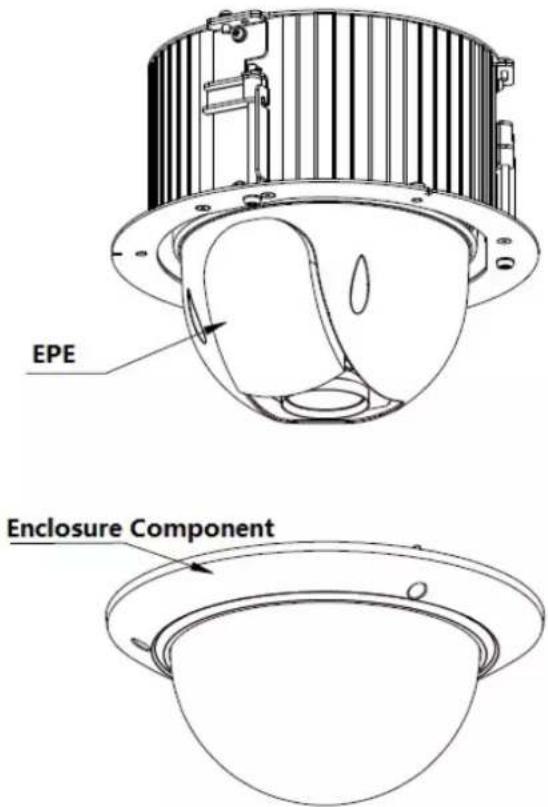
2.2 Open Device
Open the package and then take out the device, which is shown in Figure 2-1.
text_image
EPE Enclosure ComponentFigure 2-1
2.3 DIP Switch Setup
The corresponding functions of DIP switch for analog speed dome and HDCVI speed dome are different, which will be respectively introduced below.
2.3.1 DIP Switch Location and Function
Use screwdriver to dismantle the module enclosure and then you can see the DIP switch, which is shown in Figure 2-2.
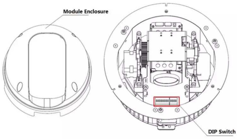
text_image
Module Enclosure DIP SwitchFigure 2-2
2.3.1.1 Analog Speed Dome
You can see there are two DIP switches on the PTZ after opening the speed dome, the two DIP switches are used to set the parameters of address, baud rate and parity, the location of DIP switch is shown in Figure 2-3.
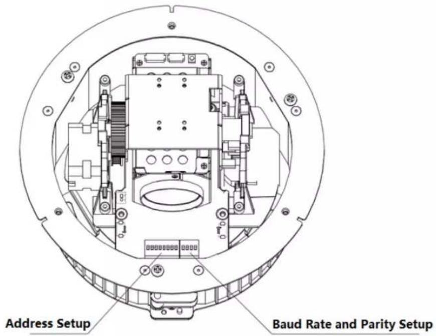
text_image
Address Setup Baud Rate and Parity SetupFigure 2-3
2.3.1.2 HDCVI Speed Dome
You can see there are two DIP switches on the PTZ after opening the speed dome, which are used to set address and baud rate of the speed dome. The location of DIP switch is shown in Figure 2-4.
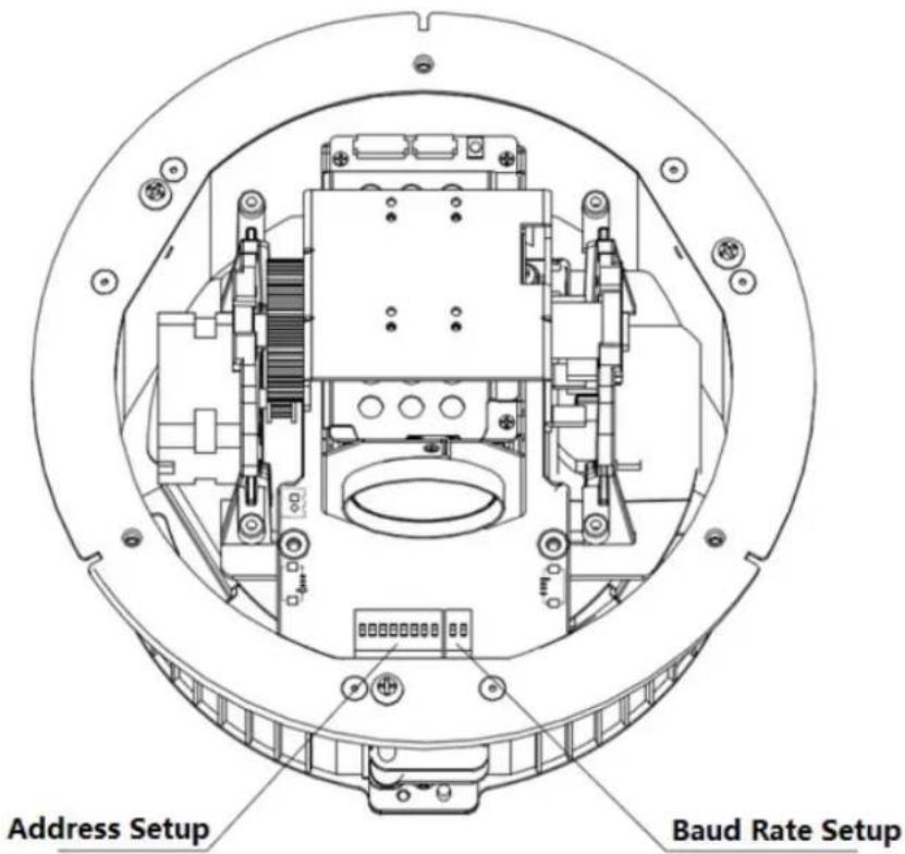
text_image
Address Setup Baud Rate SetupFigure 2-4
2.3.2 DIP Switch Setup
Before you control the speed dome, please set the speed dome address number, baud rate, and parity. The speed dome will respond to its control command after completing all these settings.
Note
- As for wall-mounted speed dome, it has to install transparent dome enclosure back in place after taking out EPE and setting DIP switch well.
- It has to cut off the power and restart the device to make new settings valid after some relevant information has been set again.
The two DIP switches on the PTZ are used to confirm the parameters of speed dome address, baud rate and parity. When you switch ON as 1, then 1 is the lowest bit and 8 is the highest bit in address setting dip switch; for baud rate and parity setting, 1 is the lowest bit and 4 is the highest bit.
Note
Please be noted that the speed dome can self-adapt to the industrial standard protocol, PELCO-D and PELCO-P, the control protocol doesn't need to be set via dip switch setting.
2.3.3 Address Setup
The speed dome can use DIP switch to set address number, the encoding mode adopts binary coding system. 1 to 8 is valid bit, and the highest address bit is 255. You can refer to Figure 2-5 for the address label, please refer to Table 2-1 for the setting of address bit.

text_image
1 | 2 | 3 | 4 | 5 | 6 | 7 | 8 AddressFigure 2-5
2.3.4 Baud Rate and Parity Setup
The functions which need to be set between analog speed dome and HDCVI speed dome will be introduced separately below.
2.3.4.1 Analog Speed Dome
It is to set speed dome baud rate and parity. Bit 1 and 2 are used to set baud rate in the dip bit from 1 to 4, bit 3 and 4 are used to set parity. Refer to Figure 2-6 for the label and please refer to Table 2-2 and Table 2-3 for baud rate and parity setup.
| 1 | 2 | 3 | 4 |
| Baud | Parity | ||
Figure 2-6
| 1 | 2 | Baud Rate |
| OFF | OFF | 9600bps |
| ON | OFF | 4800bps |
| OFF | ON | 2400bps |
| ON | ON | 1200bps |
Table 2-2
| 3 | 4 | Parity |
| OFF | OFF | NONE |
| ON | OFF | EVEN |
| OFF | ON | ODD |
| ON | ON | NONE |
Table 2-3
2.3.4.2 HDCVI Speed Dome
It is to set speed dome baud rate. Bit 1 and 2 are used to set baud rate. Please refer to Figure 2-7 for the label, refer to Table 2-4 for baud rate setup.

Figure 2-7
| 1 | 2 | Baud Rate |
| OFF | OFF | 9600bps |
| ON | OFF | 4800bps |
| OFF | ON | 2400bps |
| ON | ON | 1200bps |
Table 2-4
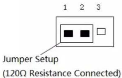
2.4 Terminal Matching Resistance Setup
There is terminal resistance 120 on the main board. There are two modes: See Figure 2-8.
| 1-2 | 2-3 | |
| 120Ω | ON | OFF |
Figure 2-8
The factory default setup is shown as in Figure 2-9. Right now, the jumper (Connection board) is on the pin 2 and pin 3. The 120Ω resistance does not connect to the device.

Factory Default Jump Setup (120Ω Resistance Unconnected)
Figure 2-9
If you want to connect the 120 resistance, please remove the jumper from the pin 2 and pin 3 and connect to pin 1 and pin 2. Now the 120 is connected to the circuit. See Figure 2-10.
text_image
Jumper Setup (120Ω Resistance Connected)Figure 2-10
2.5 Reset Button Location and SD Card Installation (Network Speed Dome)
After opening the speed dome, you can see there is a reset button on the PTZ mainboard shown as in Figure 2-11. The RESET button is used to reset network system.

text_image
Reset ButtonFigure 2-11
The Micro-SD card is installed on the camera module for data storage. See Figure 2-12.

text_image
SD Card LocationFigure 2-12
Note
- For some camera modules, the location of SD card slot is in the black circle which is shown in Figure 2-12.
- Please contact the technical support of our company if you have any questions.
2.6 Speed Dome Cable
2.6.1 Cable Description
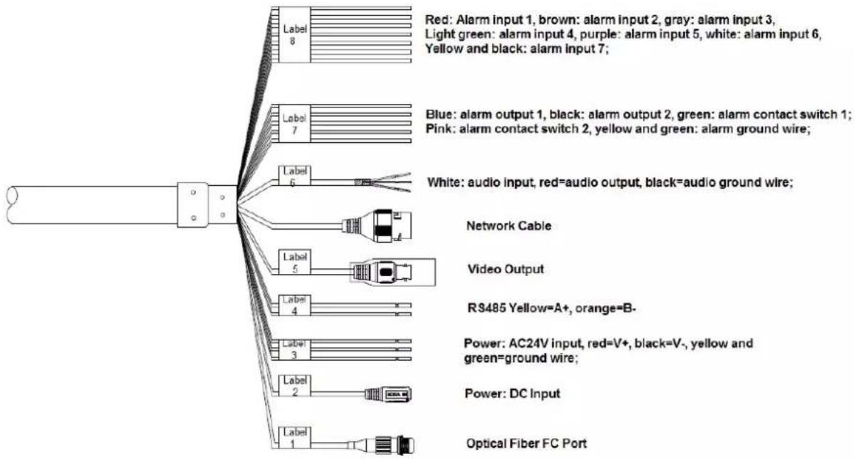
The camera is equipped with a multi-functional combination cable by default, which includes power cable, video cable, audio cable, RS485 control cable, alarm cable, network cable, high-frequency cable and optical fiber cable etc. The cable detail is shown in Figure 2-13.
text_image
Red: Alarm input 1, brown: alarm input 2, gray: alarm input 3, Light green: alarm input 4, purple: alarm input 5, white: alarm input 6, Yellow and black: alarm input 7; Blue: alarm output 1, black: alarm output 2, green: alarm contact switch 1; Pink: alarm contact switch 2, yellow and green: alarm ground wire; White: audio input, red=audio output, black=audio ground wire; Network Cable Video Output RS485 Yellow=A+, orange=B- Power: AC24V input, red=V+, black=V-, yellow and green=ground wire; Power: DC Input Optical Fiber FC PortFigure 2-13
Note
Different models have different cable combinations; please refer to the actual cable combination for more details. The cable combination is the most comprehensive example shown in the figure above.
It is prohibited to pull the cable to lift the speed dome when moving the device.
2.6.2 Cable Connection
Buckle the safety hook of speed dome on the quick mount connector; connect the integrated cable reserved by wall-mounted bracket to the corresponding power cable, video cable, audio cable, RS485 control cable, alarm cable, network cable, high-frequency cable and optical fiber cable etc. of the multi-functional combination cable of the speed dome (according to requirement), and then use insulated rubber tape to twine the cable connection well to make it waterproof.
Note
- The video port is covered with heat-shrinkable tube with high shrinkage ratio, it needs to heat and shrink the tubes on both sides after the video port is well connected, which is to make sure the video port is moistureproof and waterproof.
- During actual installation, make sure the wire diameter of the cable which is to connect to RS485 control cable can't be too big; otherwise it will affect the control effect. Please refer to appendix 2 RS485 bus for relevant introduction.
2.6.3 Alarm Cable Connection
The alarm cable connection mode and config steps are shown as follows:
Step 1
Connect alarm input device to the ALARM IN and ALARM GND of the user cable.
Step 2
Connect alarm output device to the ALARM OUT and ALARM COM of the user cable, alarm output is the relay switch output.
Step 3
Open the device WEB interface, make corresponding settings to the alarm input and output device in "Setup > Event > Alarm Setup". The alarm input of WEB is corresponding to the alarm input of the user cable. It is to set the corresponding NO and NC output according to the high and low level signal generated by alarm input device when alarm triggers.
Step 4
Set the alarm output situation of user cable on the WEB.
2.6.4 Connect Speed Dome GND Cable
Connect the power line YELLOW & GREEN of the combination cable to the lightning protection device, and make sure the lightning protection device is well grounded.
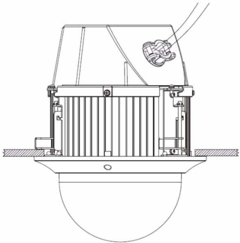
3 IN-CEILING MOUNT
3.1 Mounting Component and Dimension
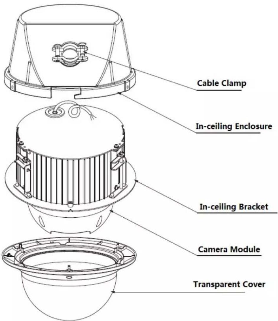
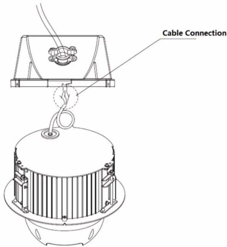
The in-ceiling bracket and main dome body are shown in Figure 3-1.
text_image
Cable Clamp In-ceiling Enclosure In-ceiling Bracket Camera Module Transparent CoverFigure 3-1
3.2 Wall-mounted Bracket Installation Steps
3.2.1 Installation Conditions
The in-ceiling speed dome can be installed on the hard construction ceiling in indoor environment.
The ceiling needs to meet the following conditions:
● The thickness of ceiling shall be between 10mm and 40mm.
- The ceiling can at least sustain the 8x weight of the speed dome, bracket and the accessories.
3.2.2 Installation Steps
Step 1
As it is shown in Figure 3-2, stick the punching position map after the mounting location is confirmed, and then take it as template to draw punching position on the ceiling and dig holes.

text_image
In-ceiling Punching Position MapFigure 3-2
Step 2
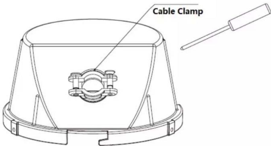
Use screwdriver to loosen the screw on the cable clamp of the in-ceiling enclosure, which is shown in Figure 3-3.
text_image
Cable ClampFigure 3-3
Step 3
Pull the cable out from the wall; insert it into the in-ceiling enclosure via cable clamp, and then use screwdriver to tighten the screw on the cable clamp, which is shown in Figure 3-4.
Note
The cable which is pulled out from wall needs to cover a fireproof metal tube that meets UL2043 standard.
natural_image
Technical line drawing of a mechanical device with a central component and two wires extending outward (no text or symbols)Figure 3-4
Step 4
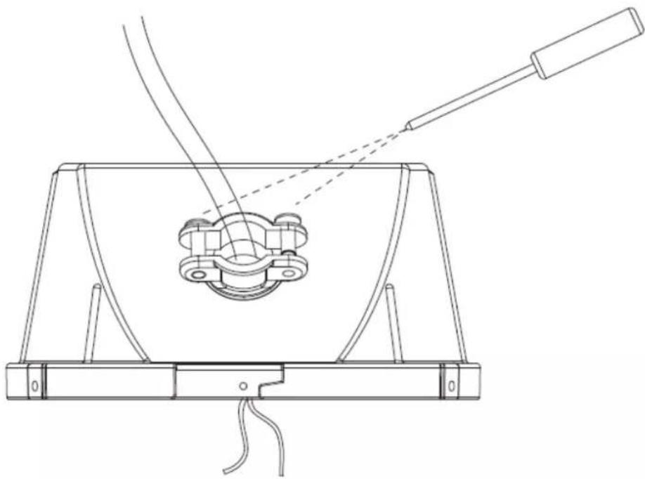
Connect the speed dome cable to the wall cable well and make it waterproof, which is shown in Figure 3-5.
text_image
Cable ConnectionFigure 3-5
Step 5
Rotate the enclosure clockwise to make the J-shaped hook fasten the flange of the camera module; Use screwdriver to tighten the screws on the enclosure edge, which is to fix the enclosure together with the camera module. Refer to Figure 3-6 for more details.
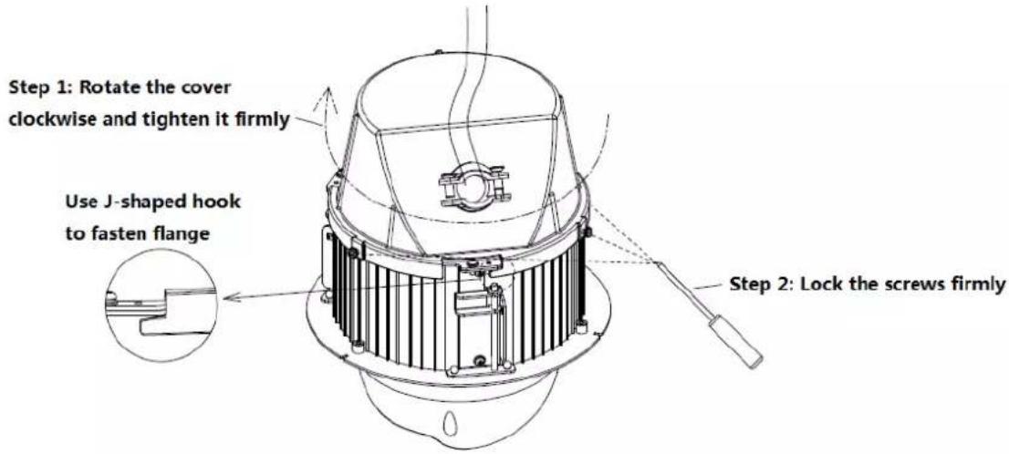
text_image
Step 1: Rotate the cover clockwise and tighten it firmly Use J-shaped hook to fasten flange Step 2: Lock the screws firmlyFigure 3-6
Step 6
Place the speed dome into the mounting holes which have been well punched, use screwdriver to rotate the three studs on the speed dome edge clockwise, which is to make three clamps on the speed dome side unfolded and lower it to the bottom to clamp ceiling. Refer to Figure 3-7 for more details.
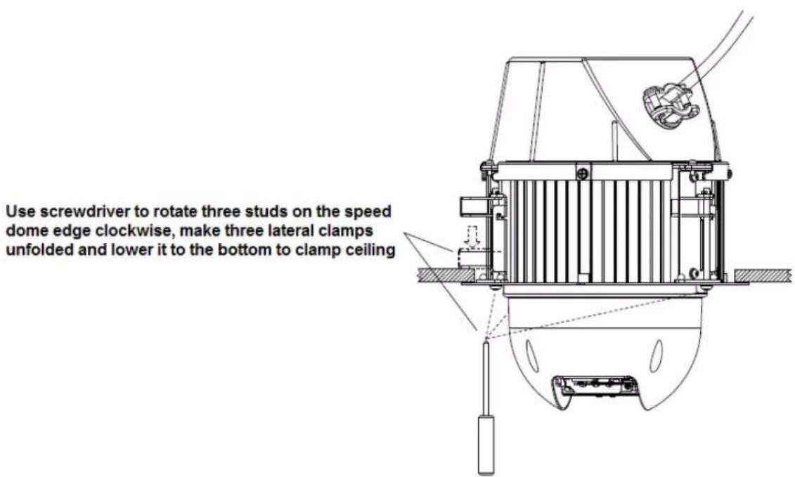
text_image
Use screwdriver to rotate three studs on the speed dome edge clockwise, make three lateral clamps unfolded and lower it to the bottom to clamp ceilingFigure 3-7
Step 7
Use three screws to fix the in-ceiling decoration cover component to the in-ceiling bracket component, and then tighten the screws. Refer to Figure 3-8 for more details.

text_image
Tighten 3 screws to install the transparent coverFigure 3-8
So far, the installation has been completed, which is shown in Figure 3-9.
natural_image
Technical line drawing of a mechanical device with no visible text or symbolsFigure 3-9
4 APPENDIX I THUNDER PROOF AND SURGE
PROTECTION (Outdoors)
This series speed dome adopts TVS lighting protection technology. It can effectively prevent damages from various pulse signals below 6000V, such as sudden lighting and surge. While maintaining your local electrical safety code, you still need to take necessary precaution measures when installing the speed dome in the outdoor environment.
- The distance between the signal transmission cable and high-voltage device (or high-voltage cable) shall be at least 50 meters.
● Outdoor cable layout shall go under the penthouse if possible. - For vast land, please use sealing steel tube under the land to implement cable layout and connects one point to the earth. Open floor cable layout is forbidden.
- In area of strong thunderstorm hit or near high sensitive voltage (such as near high-voltage transformer substation), you need to install additional high-power thunder protection device or lightning rod.
- The thunder protection and earth of the outdoor device and cable shall be considered in the building whole thunder protection and conform to your local national or industry standard.
- System shall adopt equal-potential wiring. The earth device shall meet anti-jamming and at the same time conforms to your local electrical safety code. The earth device shall not short circuit to N (neutral) line of high voltage power grid or mixed with other wires. When connect the system to the earth alone, the earth resistance shall not be more than 4Ω and earth cable cross-sectional area shall be no less than 25 mm ^2 . See Figure 4-1
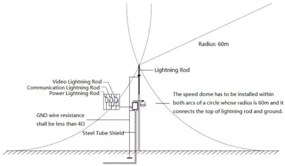
text_image
Radius: 60m Lightning Rod Video Lightning Rod Communication Lightning Rod Power Lightning Rod GND wire resistance shall be less than 4Ω Steel Tube Shield The speed dome has to be installed within both arcs of a circle whose radius is 60m and it connects the top of lightning rod and ground.Figure 4-1
4.1 Lightning Protection (Indoors)
The yellow and green GND wire or GND screw of the speed dome should be reliably connected by several strands of copper wire with no less than 25mm^2 and indoor equipotential GND terminal. Please refer to Figure 4-2 for lightningproof installation mode.
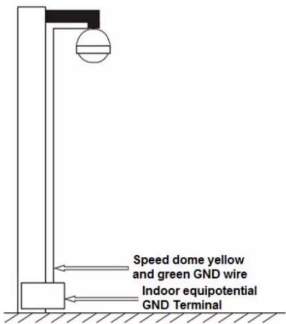
text_image
Speed dome yellow and green GND wire Indoor equipotential GND TerminalFigure 4-2
5 APPENDIX II ABOUT RS485 BUS
5.1 RS485 Bus Main Feature
RS485 is semi duplex communication cable of impedance 120 . Its max load amount is 32 effective loads (including main control device and devices to be charged).
5.2 RS485 Bus Transmission Distance
When we take 0.56mm (24AWG) twisted-pair as communication cable, the max transmission distance (theoretically) are listed below (according to different baud rates).
| Baud Rate | Max Distance |
| 2400 BPS | 1800M |
| 4800 BPS | 1200M |
| 9600 BPS | 800M |
In the following situations, the max transmission distance shall become shorter accordingly:
● The communication cable is a little bit thin;
● The surrounding environment has strong electromagnetic interference;
● There are too much devices connected to the RS485 bus;
And vice versa, the max transmission distance shall become longer.
5.3 The Problem in Practical Use
In practical usage, we usually adopt star type connection. The terminal resistance shall connect to the furthest two devices (Such as device 1# and device 15# in Figure 5-1). But this connection way does not conform to RS485 Bus standard. When the distances between devices are too long, the signal reflection occurs and anti-jamming decreases, thus the signal reliability becomes very low. You can see speed dome is not under control or speed dome is running automatically and cannot stop.
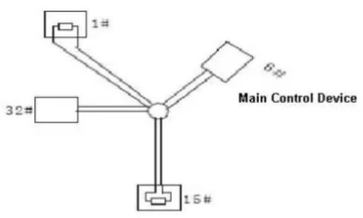
flowchart
graph TD
    A["1#"] --> C["Central Node"]
    B["32#"] --> C
    D["15#"] --> C
    E["6#"] --> C
    F["Main Control Device"] --> C
Figure 5-1
In this situation, we recommend RS485 distributor. This device can turn star type connection into the connection that conforms to RS485 bus industry standard, which can avoid the above mentioned problems and enhance communication reliability. See Figure 5-2.
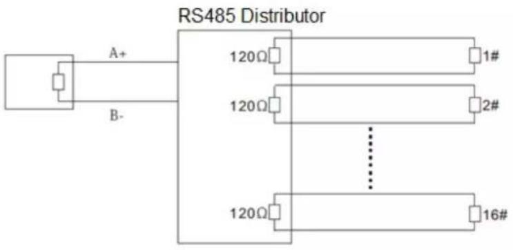
text_image
RS485 Distributor A+ B- 120Ω 1# 120Ω 2# 120Ω 16#Figure 5-2
5.4 RS485 Bus FAQ
| Phenomenon | Possible Reasons | Solution |
| Speed dome can run self-diagnosis but I cannot control it. | Host address(baud rate) and speed dome address(baud rate) are not match;Positive and negative end of RS485 Bus are misconnected;Connection cable is loose;RS485 Bus connection are cut off; | Modify host or speed dome setup ;Switch RS485 positive end and negative end;Fix connection cable firmly;Replace RS485 Bus. |
| I can control the speed dome but is not smooth | RS485 Bus connection are not good;One RS485 bus is off;The distance between host and speed dome is too far;Parallel connected too much speed domes. | Connect RS 485 Bus again ;Replace RS485 Bus;Add terminal matching resistance;Add RS485 distributor. |
6 APPENDIX III THE 24V AC WIRE GAUGE AND
TRANSMISSION DISTANCE RELATIONSHIP SHEET
It is the recommended transmission distance when the cable diameter is fixed and the 24V AC power consumption is below 10%. For the AC device, the max permission voltage power consumption is 10%. For example, when a device of rated power 20W installed from the transformer 141 inches (42m), then the min cable diameter is 0.8000mm.
| mmFeet (m)w | 0.8000 | 1.000 | 1.250 | 2.000 |
| 5 | 488.52(148.90) | 763.31(232.66) | 1192.67(363.53) | 3053.25(930.63) |
| 10 | 244.26(74.45) | 381.66(116.33) | 596.34(181.76) | 1526.62(465.31) |
| 15 | 162.84(49.63) | 254.44(77.55) | 397.56(121.18) | 1017.75(310.21) |
| 20 | 122.13(37.23) | 190.83(58.16) | 298.17(90.88) | 763.31(232.66) |
| 25 | 97.70(29.78) | 152.66(46.53) | 238.53(72.71) | 610.65(186.13) |
| 30 | 81.42(24.82) | 127.22(38.78) | 198.78(60.59) | 508.87(155.10) |
| 35 | 69.79(21.27) | 109.04(33.24) | 170.38(51.93) | 436.18(132.95) |
| 40 | 61.06(18.61) | 95.41(29.08) | 149.08(45.44) | 381.66(116.33) |
| 45 | 54.28(16.54) | 84.81(25.85) | 132.52(40.39) | 339.25(103.40) |
| 50 | 48.85(14.89) | 76.33(23.27) | 119.27(36.35) | 305.32(93.06) |
| 55 | 44.41(13.54) | 69.39(21.15) | 108.42(33.05) | 277.57(84.60) |
| 60 | 40.71(12.41) | 63.61(19.39) | 99.39(30.29) | 254.44(77.55) |
| 65 | 37.58(11.45) | 58.72(17.90) | 91.74(27.96) | 234.87(71.59) |
| 70 | 34.89(10.64) | 54.52(16.62) | 85.19(25.97) | 218.09(66.47) |
| 75 | 32.57(9.93) | 50.89(15.51) | 79.51(24.24) | 203.55(62.04) |
| 80 | 30.53(9.31) | 47.71(14.54) | 74.54(22.72) | 190.83(58.16) |
| 85 | 28.74(8.76) | 44.90(13.69) | 70.16(21.38) | 179.60(54.74) |
| 90 | 27.14(8.27) | 42.41(12.93) | 66.26(20.20) | 169.62(51.70) |
| 95 | 25.71(7.84) | 40.17(12.25) | 62.77(19.13) | 160.70(48.98) |
| 100 | 24.43(7.45) | 38.17(11.63) | 59.63(18.18) | 152.66(46.53) |
7 APPENDIX IV12V DC WIRE GAUGE AND
TRANSMISSION DISTANCE RELATIONSHIP SHEET
The recommended max transmission distance is under the following environments: The wire diameter is fixed and the DC 12V power voltage loss rate is below 10%. For the device of DC power supplying, the max allowed voltage loss rate is 10%. All the wires listed in the following
sheet are copper wire. (Copper wire resistance = 0.0175 * mm^2/m )
| mmFeet (m)w | 0.8000 | 1.000 | 1.250 | 2.000 |
| 5 | 122.13 (37.23) | 190.83 (58.16) | 298.17 (90.88) | 763.31 (232.66) |
| 10 | 61.06 (18.61) | 95.41 (29.08) | 149.08 (45.44) | 381.66 (116.33) |
| 15 | 40.71 (12.41) | 63.61 (19.39) | 99.39 (30.29) | 254.44 (77.55) |
| 20 | 30.53 (9.31) | 47.71 (14.54) | 74.54 (22.72) | 190.83 (58.16) |
| 25 | 24.43 (7.45) | 38.17 (11.63) | 59.63 (18.18) | 152.66 (46.53) |
| 30 | 20.35 (6.20) | 31.80 (9.69) | 49.69 (15.15) | 127.22 (38.78) |
| 35 | 17.45 (5.32) | 27.26 (8.31) | 42.60 (12.98) | 109.04 (33.24) |
| 40 | 15.27 (4.65) | 23.85 (7.27) | 37.27 (11.36) | 95.41 (29.08) |
| 45 | 13.57 (4.14) | 21.20 (6.46) | 33.13 (10.10) | 84.81 (28.85) |
| 50 | 12.21 (3.72) | 19.08 (5.82) | 29.82 (9.09) | 76.33 (23.27) |
| 55 | 11.10 (3.38) | 17.35 (5.29) | 27.11 (8.26) | 69.39 (21.15) |
| 60 | 10.18 (3.10) | 15.90 (4.85) | 24.85 (7.57) | 63.61 (19.39) |
| 65 | 9.39 (2.86) | 14.68 (4.47) | 22.94 (6.99) | 58.72 (17.90) |
| 70 | 8.72 (2.66) | 13.63 (4.15) | 21.30 (6.49) | 54.52 (16.62) |
| 75 | 8.14 (2.48) | 12.72 (3.88) | 19.88 (6.06) | 50.89 (15.51) |
| 80 | 7.63 (2.33) | 11.93 (3.64) | 18.64 (5.68) | 47.71 (14.54) |
| 85 | 7.18 (2.19) | 11.23 (3.42) | 17.54 (5.35) | 44.90 (13.69) |
| 90 | 6.78 (2.07) | 10.60 (3.23) | 16.56 (5.05) | 42.41 (12.93) |
| 95 | 6.43 (1.96) | 10.04 (3.06) | 15.69 (4.78) | 40.17 (12.25) |
| 100 | 6.11 (1.86) | 9.54 (2.91) | 14.91 (4.54) | 38.17 (11.63) |
8 APPENDIX V WIRE GAUGE REFERENCE SHEET
| Metric bare wire diameter (mm) | AWG | SWG | Bare wire cross section (mm2) |
| 0.050 | 43 | 47 | 0.00196 |
| 0.060 | 42 | 46 | 0.00283 |
| 0.070 | 41 | 45 | 0.00385 |
| 0.080 | 40 | 44 | 0.00503 |
| 0.090 | 39 | 43 | 0.00636 |
| 0.100 | 38 | 42 | 0.00785 |
| 0.110 | 37 | 41 | 0.00950 |
| 0.130 | 36 | 39 | 0.01327 |
| 0.140 | 35 | / | 0.01539 |
| 0.160 | 34 | 37 | 0.02011 |
| 0.180 | 33 | / | 0.02545 |
| 0.200 | 32 | 35 | 0.03142 |
| 0.230 | 31 | / | 0.04115 |
| 0.250 | 30 | 33 | 0.04909 |
| 0.290 | 29 | 31 | 0.06605 |
| 0.330 | 28 | 30 | 0.08553 |
| 0.350 | 27 | 29 | 0.09621 |
| 0.400 | 26 | 28 | 0.1257 |
| 0.450 | 25 | / | 0.1602 |
| 0.560 | 24 | 24 | 0.2463 |
| 0.600 | 23 | 23 | 0.2827 |
| 0.710 | 22 | 22 | 0.3958 |
| 0.750 | 21 | / | 0.4417 |
| 0.800 | 20 | 21 | 0.5027 |
| 0.900 | 19 | 20 | 0.6362 |
| 1.000 | 18 | 19 | 0.7854 |
| 1.250 | 16 | 18 | 1.2266 |
| 1.500 | 15 | / | 1.7663 |
| 2.000 | 12 | 14 | 3.1420 |
| 2.500 | / | / | 4.9080 |
| 3.000 | / | / | 7.0683 |
Note
● This manual is for reference only. Slight difference may be found in the user interface.
● All the designs and software here are subject to change without prior written notice.
● All trademarks and registered trademarks are the properties of their respective owners.
- If there is any uncertainty or controversy, please refer to the final explanation of us.
- Please visit our website or contact your local service engineer for more information.