6AL445XANR - Security Camera Dahua Technology - Free user manual and instructions
Find the device manual for free 6AL445XANR Dahua Technology in PDF.

User questions about 6AL445XANR Dahua Technology
0 question about this device. Answer the ones you know or ask your own.
Ask a new question about this device
Download the instructions for your Security Camera in PDF format for free! Find your manual 6AL445XANR - Dahua Technology and take your electronic device back in hand. On this page are published all the documents necessary for the use of your device. 6AL445XANR by Dahua Technology.
USER MANUAL 6AL445XANR Dahua Technology
45x PTZ Laser Network Camera with Analytics+ Installation Manual
V1.0.1
Mandatory actions to be taken towards cybersecurity
1. Change Passwords and Use Strong Passwords
The number one reason systems get “hacked” is due to having weak or default passwords. It is recommended to change default passwords immediately and choose a strong password whenever possible. A strong password should be made up of at least 8 characters and a combination of special characters, numbers, and upper and lower case letters.
2. Update Firmware
As is standard procedure in the tech-industry, we recommend keeping NVR, DVR, and IP camera firmware up-to-date to ensure the system is current with the latest security patches and fixes.
"Nice to have" recommendations to improve your network security
1. Change Passwords Regularly
Regularly change the credentials to your devices to help ensure that only authorized users are able to access the system.
2. Change Default HTTP and TCP Ports:
- Change default HTTP and TCP ports for systems. These are the two ports used to communicate and to view video feeds remotely.
- These ports can be changed to any set of numbers between 1025-65535. Avoiding the default ports reduces the risk of outsiders being able to guess which ports you are using.
3. Enable HTTPS/SSL:
Set up an SSL Certificate to enable HTTPS. This will encrypt all communication between your devices and recorder.
4. Enable IP Filter:
Enabling your IP filter will prevent everyone, except those with specified IP addresses, from accessing the system.
5. Change ONVIF Password:
On older IP Camera firmware, the ONVIF password does not change when you change the system's credentials. You will need to either update the camera's firmware to the latest revision or manually change the ONVIF password.
6. Forward Only Ports You Need:
- Only forward the HTTP and TCP ports that you need to use. Do not forward a huge range of numbers to the device. Do not DMZ the device's IP address.
- You do not need to forward any ports for individual cameras if they are all connected to a recorder on site; just the NVR is needed.
7. Disable Auto-Login on SmartPSS:
Those using SmartPSS to view their system and on a computer that is used by multiple people should disable auto-login. This adds a layer of security to prevent users without the appropriate credentials from accessing the system.
8. Use a Different Username and Password for SmartPSS:
In the event that your social media, bank, email, etc. account is compromised, you would not want someone collecting those passwords and trying them out on your video surveillance system. Using a
different username and password for your security system will make it more difficult for someone to guess their way into your system.
9. Limit Features of Guest Accounts:
If your system is set up for multiple users, ensure that each user only has rights to features and functions they need to use to perform their job.
10. UPnP:
- UPnP will automatically try to forward ports in your router or modem. Normally this would be a good thing. However, if your system automatically forwards the ports and you leave the credentials defaulted, you may end up with unwanted visitors.
- If you manually forwarded the HTTP and TCP ports in your router/modem, this feature should be turned off regardless. Disabling UPnP is recommended when the function is not used in real applications.
11. SNMP:
Disable SNMP if you are not using it. If you are using SNMP, you should do so only temporarily, for tracing and testing purposes only.
12. Multicast:
Multicast is used to share video streams between two recorders. Currently there are no known issues involving Multicast, but if you are not using this feature, deactivation can enhance your network security.
13. Check the Log:
If you suspect that someone has gained unauthorized access to your system, you can check the system log. The system log will show you which IP addresses were used to login to your system and what was accessed.
14. Physically Lock Down the Device:
Ideally, you want to prevent any unauthorized physical access to your system. The best way to achieve this is to install the recorder in a lockbox, locking server rack, or in a room that is behind a lock and key.
15. Connect IP Cameras to the PoE Ports on the Back of an NVR:
Cameras connected to the PoE ports on the back of an NVR are isolated from the outside world and cannot be accessed directly.
16. Isolate NVR and IP Camera Network
The network your NVR and IP camera resides on should not be the same network as your public computer network. This will prevent any visitors or unwanted guests from getting access to the same network the security system needs in order to function properly.
General
This Installation Manual (hereinafter referred to be "the Manual") introduces installation preparation, speed dome installation, bracket dimension, and bracket installation including wall-mounted bracket installation, hang-mounted bracket installation, corner-mounted bracket installation, and pole-mounted bracket installation.
Safety Instructions
The following categorized signal words with defined meaning might appear in the Manual.
| Signal Words | Meaning |
 DANGER DANGER | Indicates a high potential hazard which, if not avoided, will result in death or serious injury. |
 WARNING WARNING | Indicates a medium or low potential hazard which, if not avoided, could result in slight or moderate injury. |
 CAUTION CAUTION | Indicates a potential risk which, if not avoided, could result in property damage, data loss, lower performance, or unpredictable result. |
 PS PS | Provides methods to help you solve a problem or save you time. |
 RE RE | Provides additional information as the emphasis and supplement to the text. |
Revision History
| No. | Version | Revision Content | Release Time |
| 1 | V1.0.0 | First Release. | August 2, 2018 |
Privacy Protection Notice
As the device user or data controller, you might collect personal data of other such as face, fingerprints, car plate number, Email address, phone number, GPS and so on. You need to be in compliance with the local privacy protection laws and regulations to protect the legitimate rights and interests of other people by implementing measures include but not limited to: providing clear and visible identification to inform data subject the existence of surveillance area and providing related contact.
About this Manual
- The Manual is for reference only. If there is inconsistency between the Manual and the actual product, the actual product shall prevail.
- We are not liable for any loss caused by the operations that do not comply with the Manual.
- The Manual would be updated according to the latest laws and regulations of related regions. For detailed information, see the paper manual, CD-ROM, QR code or our official website. If there is inconsistency between paper manual and the electronic version, the electronic version shall prevail.
- All the designs and software are subject to change without prior written notice. The product updates might cause some differences between the actual product and the Manual. Please contact the customer service for the latest program and supplementary documentation.
- There still might be deviation in technical data, functions and operations description, or errors in print. If there is any doubt or dispute, please refer to our final explanation.
- Upgrade the reader software or try other mainstream reader software if the Manual (in PDF format) cannot be opened.
- All trademarks, registered trademarks and the company names in the Manual are the properties of their respective owners.
- Please visit our website, contact the supplier or customer service if there is any problem occurred when using the device.
- If there is any uncertainty or controversy, please refer to our final explanation.
Important Safeguards and Warnings
The Manual helps you to use our product properly. Read the Manual carefully before installing and using the product, and we highly recommend you to keep it well for future reference.

CAUTION
- Avoid heavy stress, violent vibration, and water splash during transportation, storage, and installation.
- Complete package is necessary during the transportation. We will assume no responsibility for any damage or problem caused by the incomplete package during the transportation.
- Avoid the product falling down or heavy vibration.
- Buckle the safety hook before installing the product if it is included.
- Keep the product away from devices that might produce strong electromagnetism radiant, including wireless power, TV transmitter, transformer, and loudspeaker.
- Keep the product away from smoke, vapor, dust, and heat. Do not install the speed dome near the heating furnace, spotlight, and other heat source.
- Do not dissemble the product. A failure to follow this instruction might result in personal injury or device damage. Contact your local retailer or customer service center for internal setup or maintenance requirement.
- Make sure there is no metal or inflammable in the product. A failure to follow this instruction might result in fire, short-circuit, or other damage.
- Turn off the power and disconnect the power cable immediately if there is water or liquid falling into the product. And contact your local retailer or customer service center.
- Avoid the sea water or rain eroding the camera.
- Avoid the lens aiming at intense light source, including sunlight and incandescent light.
- Clean the enclosure with the soft cloth or soft cloth with proper cleaning liquid, and then dry it with soft cloth. Do not use gasoline, dope thinner, or other chemicals to clean the enclosure. A failure to follow this instruction might result in enclosure transfiguration or paint flake.
- Read all the Manuals included before you use chemical cloth.
- Avoid long time touch between the plastic or rubber material and the enclosure. A failure to follow this instruction might result in paint flake.
- It is highly recommended to use the product with a lightning-proof device for better lightning-proof effect.
Qualified Engineer Needed
The installation engineer or maintenance engineer shall have corresponding CCTV system installation certificate or maintenance qualification certificate, including qualification certificate for work at height.
- The installation engineer or maintenance engineer shall have the basic knowledge and installation technique for CCTV system.
- The installation engineer or maintenance engineer shall have the basic knowledge and operation technique for low-voltage cable wiring and low-voltage electronic cable connection.
- The installation engineer or maintenance engineer shall be able to read and understand the Manual.
Lifting Appliance Requirements
- Select the lifting appliances applicable for the speed dome installation environment and installation method.
- The lifting appliances shall have the enough capacity to reach the installation height.
- The lifting appliances shall have high security performance.

WARNING
- All installation and operation here should conform to your local electrical safety regulations. We will assume no responsibility for all the fires or electrical shock caused by improper handling or installation.
- The power supply shall meet the SELV requirement. Use the power supply that conforms to Limited Power Source, according to IEC60950-1.
- Use the power adapter recommended by manufacturer.
- For the product that supports laser, do not aim the laser directly to eyes. And keep a proper distance from the flammable to avoid fire.
- Do not connect several speed domes to one power adapter. A failure to follow this instruction might result in overheat or fire if it exceeds the rated load.
- Make sure the power is off when you connect the cables, install or uninstall the speed dome.
- Turn off the power and disconnect the power cable immediately if there is any smoke, disgusting smell, or noise from the speed dome. And contact your local retailer or customer service center.
- Contact your local retailer or customer service center if the product is abnormal. Do not disassemble or repair the product by yourself. We will assume no responsibility for any problems caused by unauthorized modifications or repair.
- We will assume no responsibility for any problems caused by incorrect installation or use.
- We will assume no responsibility for any problems caused by overuse of the certain component.
Table of Contents
Cybersecurity Recommendations....I
Foreword....III
Important Safeguards and Warnings....V
Table of Contents ......VII
1 Installation Preparation....1
1.1 Basic Requirements....1
1.2 Installation Check .... 1
1.3 Cable Preparation....1
2 IR Speed Dome Installation....2
2.1 Checking Accessories....2
2.2 Opening the Package....2
2.3 Reset Button and Micro SD Card....3
2.4 Speed Dome Installation....4
2.4.1 Installing Quick Mounting Connector....4
2.4.2 Speed Dome Cable 4
2.4.3 Installing the Speed Dome 7
3 Wall-mounted Bracket Installation 9
3.1 Dimension 9
3.2 Installing Wall-mounted Bracket....10
3.2.1 Installation Conditions....10
3.2.2 Installation Procedure 10
4 Hang-mounted Bracket Installation....12
4.1 Dimension 12
4.2 Installing Hang-mounted Bracket 13
4.2.1 Installation Conditions....13
4.2.2 Installation Procedure 13
5 Corner-mounted Bracket Installation....15
5.1 Dimension 15
5.2 Installing Corner-mounted Bracket.... 16
5.2.1 Installation Conditions.... 16
5.2.2 Installation Procedure 16
6 Pole-Mounted Bracket Installation 18
6.1 Dimension 18
6.2 Installing Pole-mounted Bracket 19
6.2.1 Installation Conditions....19
6.2.2 Installation Procedure 20
1.1 Basic Requirements
- All installation and operation here should conform to your local electrical safety regulations, fire protection regulations, and relevant regulations.
- Make sure the application scenarios conform to the installation requirements. Contact your local retailer or customer service center if there is any problem.
- Use the product according to the operating environment.
- Keep the original packing material well, you might need it to pack the speed dome and send it back for repair.
1.2 Installation Check
- Make sure the installation environment has enough space to install the speed dome and its mounting accessories.
- Make sure the ceiling and wall can sustain at least eight times the weight of the speed dome and its mounting accessories.
- Make sure the wall is thick enough to install expansion bolts (The expansion bolts should be purchased separately).
- For intelligent tracking speed dome, traffic speed dome, or laser speed dome, make sure the mounting height is over 6 m.
1.3 Cable Preparation
Select the video cable and video coaxial cable according to the transmission distance.
2.1 Checking Accessories
Before installation, check the accessories according to the packing list, and make sure all the components listed are included.
2.2 Opening the Package
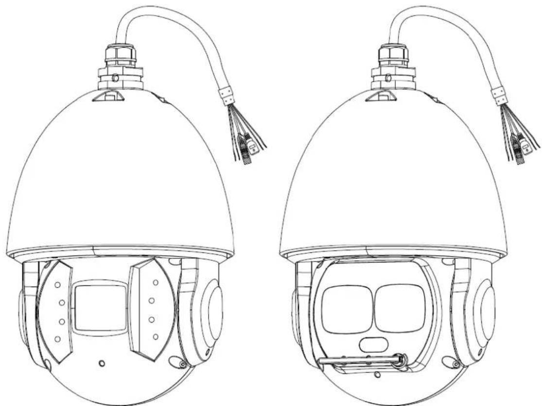
Open the package, and take out the speed dome. See Figure 2-1.
Figure 2-1 IR Speed Dome
natural_image
Technical line drawing of two identical helmet designs with no text or symbols
- The speed dome appearances might be different depending on the model you purchased, and the actual product shall prevail.
- For laser speed dome, there is the laser light and IR light on the speed dome. The laser light is for light supplement, and the IR light is for indicating whether the laser light is on or off.
2.3 Reset Button and Micro SD Card
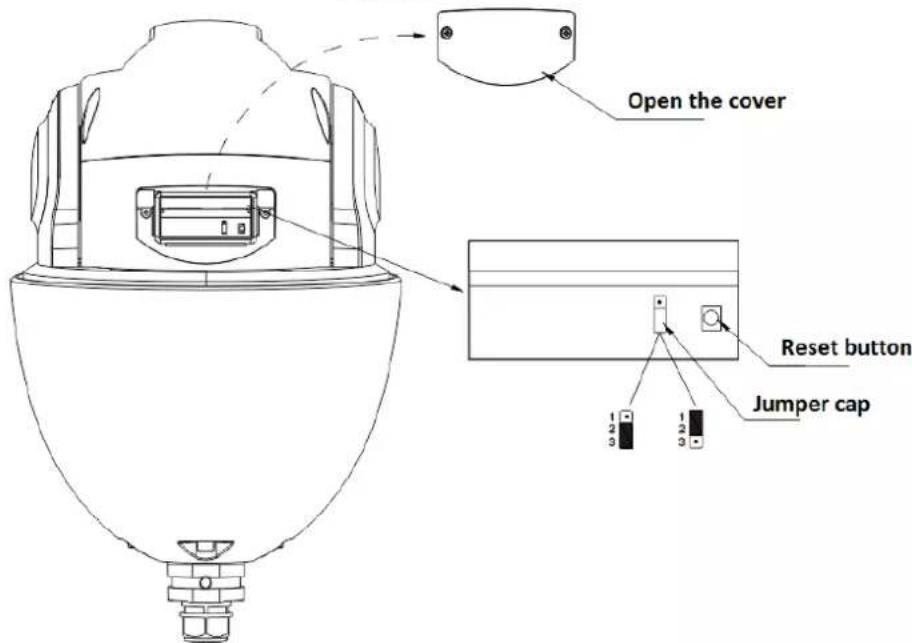
Open the cover on the speed dome and you can see the Reset button on the PTZ mainboard. See Figure 2-10. Open the front dome component and you can see the Micro SD card slot on the ISP board of speed dome module. See Figure 2-11.
Reset button is for resetting network system, and Micro SD card is for data storage.
Figure 2-2 Reset button
text_image
Open the cover Reset button Jumper cap 1 2 3 1 2 3Figure 2-3 Micro SD card

text_image
Open the front dome component Micro SD card2.4 Speed Dome Installation

The installation steps are applicable for both analog speed domes and network speed domes.
Various types of brackets are supported for the speed domes in different installation conditions. For details about speed dome installation, see "3 Wall-mounted Bracket Installation" to "6 Pole-Mounted Bracket Installation".
The Manual takes analog speed dome installation with wall-mounted bracket as the example.
2.4.1 Installing Quick Mounting Connector
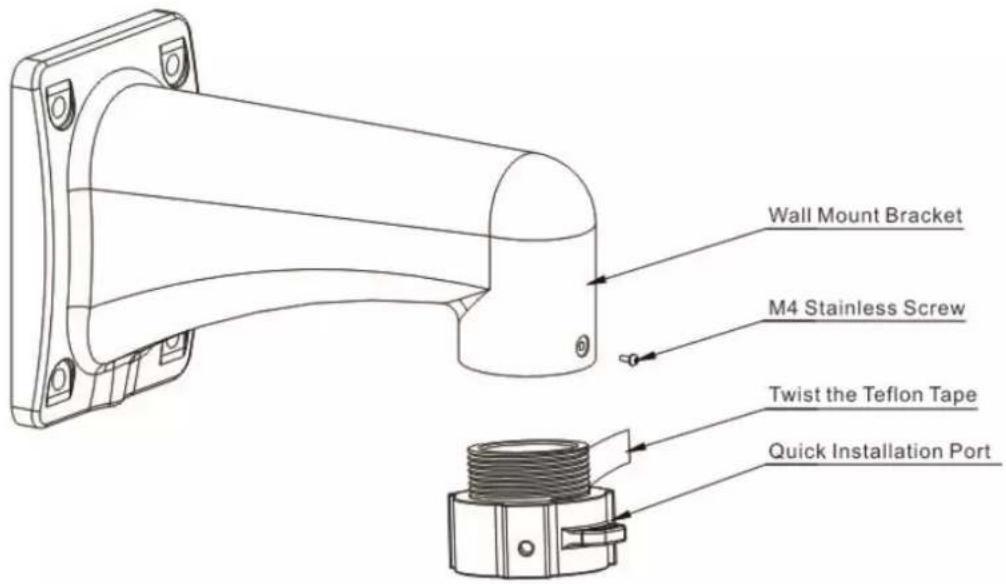
Twine Teflon tape around the screw thread of the quick mounting connector, and rotate it into the screw thread of the wall-mounted bracket. Secure it firmly with an M4 stainless screw. See Figure 2-12. The thread standard is G1 1/2 pipe thread.
Figure 2-4 Installing quick mounting connector
text_image
Wall Mount Bracket M4 Stainless Screw Twist the Teflon Tape Quick Installation Port2.4.2 Speed Dome Cable
2.4.2.1 Cable Description
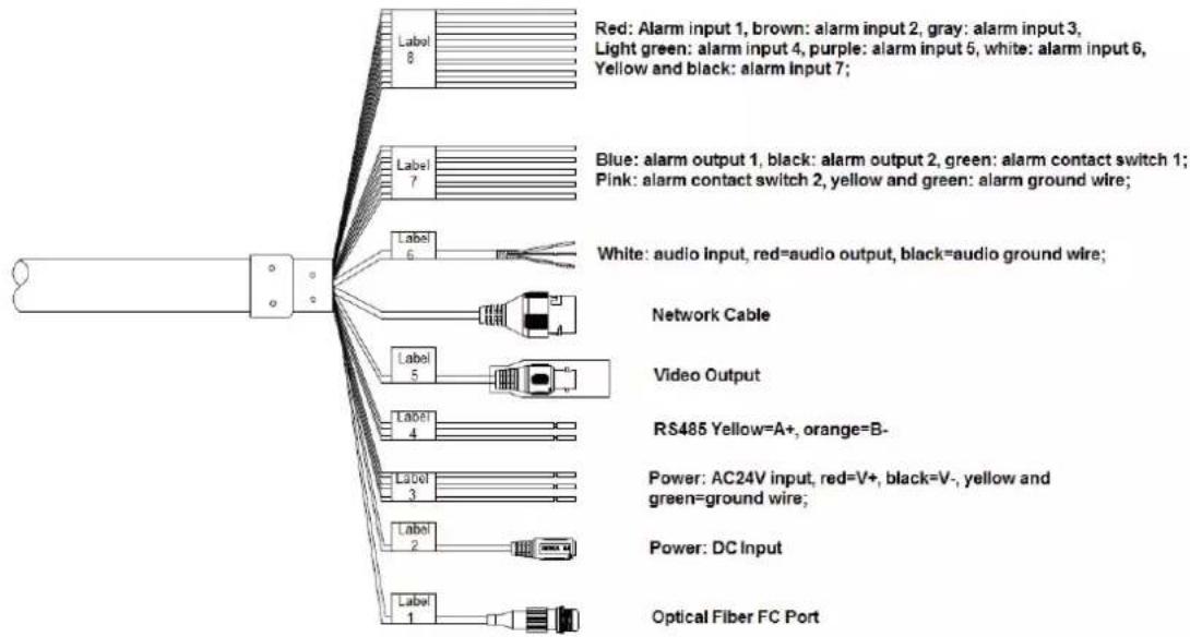
The speed dome is equipped with a composite cable by default, including power cable, video cable, audio cable, RS-485 control cable, alarm cable, network cable, high-frequency cable, and optical fiber cable. See Figure 2-13.
Figure 2-5 Cables
text_image
Red: Alarm input 1, brown: alarm input 2, gray: alarm input 3, Light green: alarm input 4, purple: alarm input 5, white: alarm input 6, Yellow and black: alarm input 7; Blue: alarm output 1, black: alarm output 2, green: alarm contact switch 1; Pink: alarm contact switch 2, yellow and green: alarm ground wire; White: audio Input, red=audio output, black=audio ground wire; Network Cable Video Output RS485 Yellow=A+, orange=B- Power: AC24V input, red=V+, black=V-, yellow and green=ground wire; Power: DC Input Optical Fiber FC Port
Speed dome cables might vary depending on the model you purchased, and the actual product shall prevail. The Manual introduces the complete cables for you.
Do not drag or pull the cables to lift the speed dome when moving it. See Figure 2-14 for wrong way.
Figure 2-6 Wrong way for moving the speed dome

natural_image
Simple line drawing of a device with a handle, cross symbol, and base (no text or labels)2.4.2.2 Cable Connection
Buckle the safety hook of the speed dome on the quick mounting connector, and connect the cables reserved on the wall-mounted bracket with the corresponding cables of the speed dome as you need. Then twine the cable connection with insulated rubber tape to ensure waterproof. See Figure 2-15.

Make sure the wire diameter of the cable connected to RS-485 control cable is not too big. Otherwise, the control effect might be bad. See Appendix 2 for details about RS-485 cable.
Figure 2-7 Cable connection
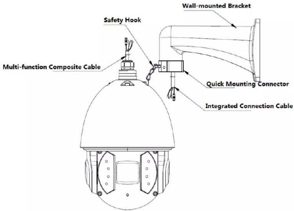
text_image
Multi-function Composite Cable Safety Hook Wall-mounted Bracket Quick Mounting Connector Integrated Connection Cable2.4.2.3 Alarm Cable Connection
To connect alarm cables and configure alarm settings, do the following:
Step 1 Connect alarm input device to the ALARM_IN and ALARM_GND of the cables.
Step 2 Connect alarm output device to the ALARM_OUT and ALARM_COM of the cables. Alarm output is the relay switch output.
Step 3 Enter the web interface of the speed dome, and set the corresponding alarm input and output by selecting Setting > Event > Alarm Setup. The alarm input on web interface is corresponding to the alarm input of the cables. Set the corresponding NO and NC output according to the high/low level signal generated by alarm input device when alarm triggers.
Step 4 Set the alarm output of cables on web interface.
2.4.2.4 Speed Dome GND Cable Connection
Connect the YELLOW/GREEN power cable to the lightning protection device, and make sure the lightning protection device is well grounded.
2.4.3 Installing the Speed Dome
To install the speed dome, do the following:
Step 1 Buckle the safety hook, and route the cables into the wall-mounted bracket.
Step 2 Align the speed dome flange with that on the quick mounting connector, and push the speed dome to the quick mounting connector.
Step 3 Screw the M6*14 stainless screw with spring washer on the quick mounting connector into the 6.5 hole on the speed dome flange, and screw another two M6*14 stainless screws on the speed dome flange. Secure the three screws with the Allen wrench. See Figure 2-16.
Figure 2-8 Installing the speed dome
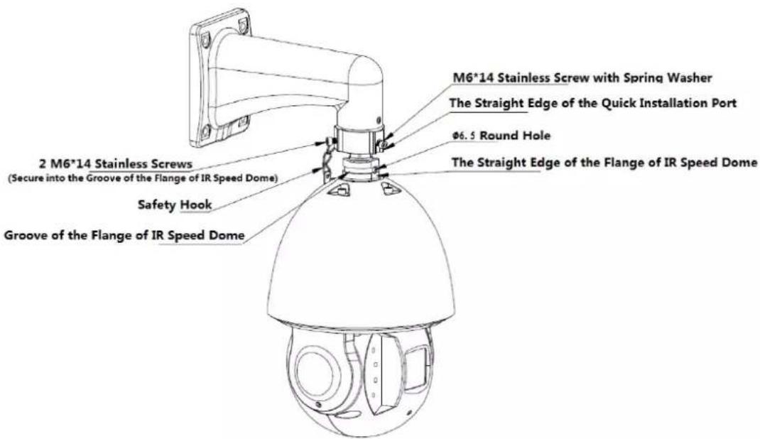
text_image
M6*14 Stainless Screw with Spring Washer The Straight Edge of the Quick Installation Port Ø6.5 Round Hole 2 M6*14 Stainless Screws (Secure into the Groove of the Flange of IR Speed Dome) Safety Hook Groove of the Flange of IR Speed DomeStep 4 Make sure three M6*14 stainless screws are firmly screwed, and the speed dome is firmly secured. See Figure 2-17.
Figure 2-9 Installation finished

natural_image
Line drawing of a security camera with mounted sensor array (no text or symbols)3.1 Dimension
See Figure 3-1 for wall -mounted bracket, and see Figure 3-2 and Figure 3-3 for dimension of the bracket and the quick mounting connector.
Figure 3-1 Wall-mounted bracket
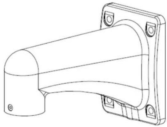
natural_image
Technical line drawing of a mechanical bracket component (no text or symbols)Figure 3-2 Dimension of wall-mounted bracket (mm)

natural_image
Technical line drawing of a mechanical bracket component (no text or symbols)
text_image
255 Ø58 G1 1/2 Pipe Thread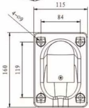
text_image
4-Ø9 160 119 84 115Figure 3-3 Dimension of quick mounting connector (mm)

text_image
G1 1/2 Pipe Thread 19.0 49.03.2 Installing Wall-mounted Bracket
3.2.1 Installation Conditions
The wall-mounted bracket is applicable to hard wall in both indoor and outdoor environments. Make sure:
- The wall shall be thick enough to install expansion bolts.
- The wall shall sustain at least eight times the weight of the speed dome and its mounting accessories.
3.2.2 Installation Procedure
Step 1 Draw and drill four screw holes on the wall according to the bracket pedestal. Insert four expansion bolts (not supplied) into the screw holes. See Figure 3-4.
Step 2 Fix the wall-mounted bracket with four hex nuts and four flat gaskets on the wall.
Figure 3-4 Install wall-mounted bracket

text_image
Mounting HoleStep 3 Install the speed dome on the wall-mounted bracket. See Figure 3-5. For details about speed dome installation, see "2.6 Speed Dome Installation".
Figure 3-5 Installing the speed dome with wall-mounted bracket

natural_image
Line drawing of a security camera with mounted sensor array (no text or symbols)4.1 Dimension
See Figure 4-1 for hang-mounted bracket, and see Figure 4-2 for dimension of the bracket.
Figure 4-1 Hang-mounted bracket

text_image
Connection Plate Decoration Cover Connection PoleFigure 4-2 Dimension of hang-mounted bracket (mm)

text_image
Ø134 236 Ø53 G1 1/2 Pipe Thread 4-Ø10 Ø100
The length of the hang-mounted bracket is 200 mm by default, and 400 mm optional. Select different sizes of the connection poles as you need.
4.2 Installing Hang-mounted Bracket
4.2.1 Installation Conditions
The hang-mounted bracket is applicable to hard wall in both indoor and outdoor environments.
Make sure:
- The wall shall be thick enough to install expansion bolts.
- The wall shall sustain at least eight times the weight of the speed dome and its mounting accessories.
4.2.2 Installation Procedure
Step 1 Loosen the M4 screw, and separate the connection plate and the connection pole of the bracket.
Step 2 Route the cables through the groove to the flange of the connection plate. Fix the connection plate on the ceiling with four screws. See Figure 4-3.
Figure 4-3 Installing hang-mounted bracket (1)

text_image
Silica Gel Connection Plate
For outdoor environment, apply silica gel to cover the contact surface between connection plate and ceiling, and cable outlet area for waterproof.
Step 3 Route the cables through the connection pole, and fix the connection pole on the connection plate with the M4 screw. Push the decorative cover to the bottom of the connection pole. See Figure 4-4.
Figure 4-4 Installing hang-mounted bracket (2)

text_image
Twine Teflon Tape Connection Pole Decoration Cover
For outdoor environment, twine Teflon tape on the thread of the connection pole first, and then fix the connection pole on the connection plate.
Step 4 Install the speed dome on the hang-mounted bracket, see Figure 4-5. For details about speed dome installation, see "2.6 Speed Dome Installation".
Figure 4-5 Installing the speed dome with hang-mounted bracket
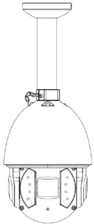
natural_image
Technical line drawing of a surveillance camera with dome and mounted sensor (no text or symbols)5.1 Dimension
See Figure 5-1 for corner-mounted bracket, and see Figure 5-2 for dimension of the bracket.
Figure 5-1 Corner-mounted bracket
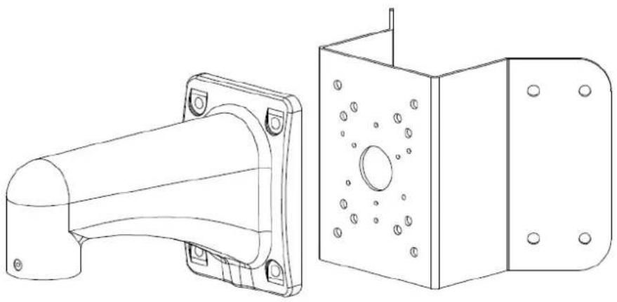
natural_image
Technical line drawing of a mechanical bracket and its side view (no text or symbols)Figure 5-2 Dimension of corner-mounted bracket (mm)
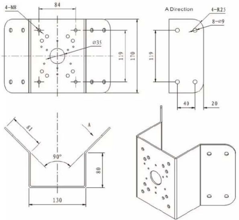
text_image
4-M8 84 Ø35 119 170 A Direction 4-R25 8-Ø9 119 40 20 Ø1 90° 80 1305.2 Installing Corner-mounted Bracket
5.2.1 Installation Conditions
The corner-mounted bracket is applicable to hard wall which forms an included angle of 90^ in both indoor and outdoor environments.
Make sure:
- The wall shall be thick enough to install expansion bolts.
- The wall shall sustain at least eight times the weight of the speed dome and its mounting accessories.
5.2.2 Installation Procedure
Step 1 Draw and drill the screw holes on the wall where there is the 90^ included angle according to the mounting hole on the corner-mounted bracket pedestal, and insert M8 expansion screws. See Figure 5-3.
Step 2 Route the cables through the corner-mounting bracket pedestal (reserve enough length of the cables), and fix the pedestal on the wall with the M8 screws. Apply silicon sealant to cover the cable outlet for waterproof.
Figure 5-3 Installing corner-mounted bracket

text_image
Mounting HoleStep 3 Install the speed dome on the corner-mounted bracket, see 错误!未找到引用源。. For details about speed dome installation, see "2.6 Speed Dome Installation" and "3.2 Installing Wall-mounted Bracket".
Figure 5-4 Installing the speed dome with corner-mounted bracket
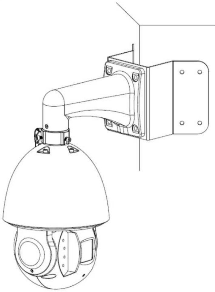
natural_image
Technical line drawing of a security camera mounted on a wall-mounted unit (no text or symbols)6.1 Dimension
See Figure 6-1 for pole-mounted bracket, and see Figure 6-2 for dimension of the bracket.
Figure 6-1 Pole-mounted bracket

natural_image
Technical line drawing of a mechanical bracket and its corresponding multi-layered assembly (no text or symbols)Figure 6-2 Dimension of pole-mounted bracket (mm)

6.2 Installing Pole-mounted Bracket
6.2.1 Installation Conditions
The pole-mounted bracket is applicable to hard wall in both indoor and outdoor environments. Make sure:
- The diameter of the pole where you want to install the speed dome shall match with the dimension of the clamp. The default clamp is the 5 inch clamp matches with the pole of 80–130 mm. The clamp shall work with the pole-mounted bracket, and the diameter of the clamp is adjustable according to the hoop specification. We provide clamps of different dimension: 59–82mm, 84–108 mm, 80–130 mm, 130–152 mm, 155–178 mm, 180–203 mm, and 194–216 mm. We also provide customized clamps of special dimensions.
- The wall shall sustain at least eight times the weight of the speed dome and its mounting accessories.
6.2.2 Installation Procedure
Step 1 Route the cables through the pole-mounted bracket pedestal. Install the clamp on the pole where you want to install the speed dome, and adjust the diameter of the clamp to fix it on the pole. See Figure 6-3.
Figure 6-3 Pole-mounted bracket
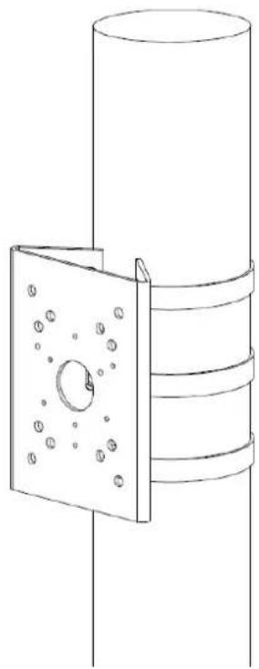
natural_image
Technical line drawing of a mechanical assembly with a flanged bracket and cylindrical housing (no text or symbols)CAUTION
Make sure the clamp is firmly fixed on the pole.
Step 2 Install the speed dome on the pole-mounted bracket, see 错误!未找到引用源。. For details about speed dome installation, see "2.6 Speed Dome Installation" and "3.2 Installing Wall-mounted Bracket".
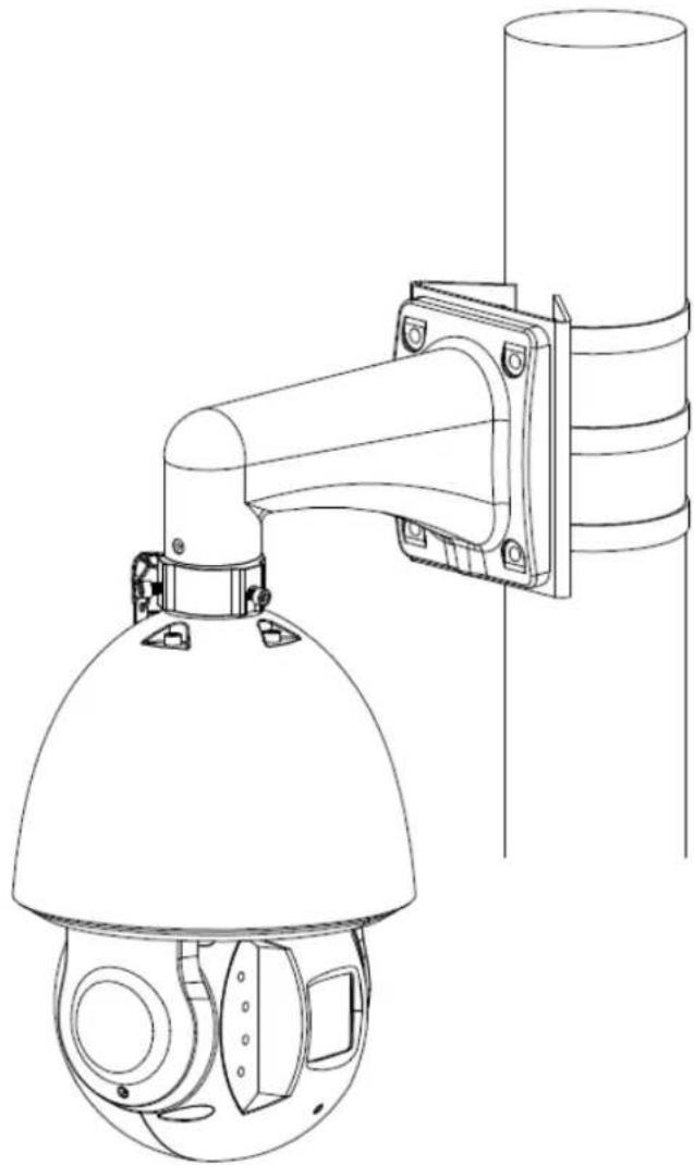
Figure 6-4 Installing the speed dome with pole-mounted bracket