DocuColor 5000AP - Printer XEROX - Free user manual and instructions
Find the device manual for free DocuColor 5000AP XEROX in PDF.

User questions about DocuColor 5000AP XEROX
0 question about this device. Answer the ones you know or ask your own.
Ask a new question about this device
Download the instructions for your Printer in PDF format for free! Find your manual DocuColor 5000AP - XEROX and take your electronic device back in hand. On this page are published all the documents necessary for the use of your device. DocuColor 5000AP by XEROX.
USER MANUAL DocuColor 5000AP XEROX
DocuColor 5000AP User Guide
© Copyright 2008 by Xerox Corporation. All Rights Reserved.
Copyright protection claimed includes all forms and matters of copyrighted material and information now allowed by statutory or judicial law or hereinafter granted, including without limitation, material generated from the software programs that are displayed on the screen such as styles, templates, icons, screen displays, looks, etc.
Xerox ^® and all Xerox product names and product numbers mentioned in this publication are trademarks of XEROX CORPORATION. Other company brands and product names may be trademarks or registered trademarks of the respective companies and are also acknowledged.
This product includes software developed by the Apache Software Foundation (http://www.apache.org/).
Table of contents
1. Overview 1-1
Identifying the digital press components....1-2
External components 1-2
Other external components. 1-4
Dry Ink/Toner Waste Bottle 1-4
Ground Fault Indicator (GFI) circuit breakers ..... 1-5
Identifying the internal components 1-6
Serial number label 1-6
Dry Ink/Toner Cartridges 1-7
Transport Module 1-7
Paper Transport Drawer 1-8
Exit Module 1-9
Paper path in the digital press 1-10
User Interface (UI) 1-10
Application menu area 1-12
System menu 1-12
Machine Details....1-12
Help menu. 1-13
Job/System Status area 1-14
Job Summary 1-14
Machine mimic and Message area 1-15
Tray status area 1-16
Main control buttons 1-16
Logon and current User level 1-16
Current User Level 1-17
Language 1-17
Power Saver 1-18
Pause 1-19
Dry Ink/Toner status area 1-19
Operator/Administrator buttons.... 1-20
Billing & Counters 1-21
Consumables 1-22
Administrator buttons 1-23
Relocating the digital press.... 1-23
Customer documentation updates....1-24
2. Tray Properties 2-1
Overview.... 2-1
Tray Properties window 2-2
Current tray information 2-3
Not available for.... 2-3
Auto Tray Switching 2-3
Auto Paper Selection 2-3
Enable/Disable 2-3
Size 2-4
Custom Paper Size 2-4
Type 2-4
Weight. 2-4
Decurler Profile 2-5
Alignment Profile. 2-6
Display.... 2-7
Help button 2-7
Selections made on the Tray Properties window ..... 2-7
Basic paper information 2-8
3. Paper information 3-1
Recommended Materials List (RML) 3-1
Paper handling 3-1
Paper guidelines....3-3
Curl 3-4
Paper specifications 3-5
Transparency guidelines.... 3-6
Tabbed inserts....3-6
Drilled paper 3-7
1-Sided Print Jobs....3-7
2-Sided Print Jobs....3-7
Letterhead....3-8
Custom (nonstandard) size paper. 3-8
Paper weight conversion tables 3-9
Specific weight conversion 3-9
Weight conversion ranges 3-10
Loading paper.... 3-11
Paper trays air adjustment:....3-12
Tray Stock Mismatch. 3-13
4. Accessories 4-1
Trays 3 and 4 (Second Feeder Module) ..... 4-1
Identifying the parts. 4-1
Paper path 4-2
Paper guidelines 4-2
Paper Specifications 4-3
Loading paper....4-4
Paper trays air adjustment 4-4
Jam clearance 4-4
Physical characteristics. 4-4
Size 4-4
Weight. 4-4
Floor space requirements 4-4
High Capacity Stacker 4-5
Identifying the parts. 4-6
Control panel. 4-6
Cooling fan 4-7
Paper path 4-9
Top Tray 4-9
Stacker Tray 4-9
Bypass 4-9
Paper guidelines 4-10
Recommended baseline/centerline. 4-10
Paper specifications 4-11
Unloading the Stacker Tray.... 4-12
Selecting Features 4-13
How to Enable Automatic Output Switching ..... 4-13
Using a DFA Finishing Device 4-13
Jam clearance 4-13
Clear Bypass area jam 4-14
Clear Top Tray and Stacker Tray paper jams ..... 4-15
Maintenance 4-15
Problem Solving 4-16
Loss of Power 4-17
Common Stacker/Stapler (CSS) 4-18
Identifying CSS Parts 4-18
Control Panel 4-19
Electrical/environmental requirements ..... 4-20
Paper stock specifications 4-20
Paper Path 4-22
Using the stacker/stapler 4-23
Hints and tips 4-23
Stapling Hints 4-23
Paper specifications for stapling 4-24
Staple Positions 4-25
Stapling capacity for different paper types and weights .. 4-27
Unloading the stacker/stapler 4-27
Jam Clearance 4-28
Ordering and Loading Staples 4-29
Stacker/stapler Maintenance....4-30
Cleaning the stacker/stapler 4-30
Problem Solving 4-30
Loss of Power 4-33
5. Problem solving 5-1
General problems 5-1
Jam clearance 5-5
Paper tray jams. 5-6
Upper Transport Area jam 5-7
Transport Module jams 5-8
Exit Module jams 5-9
Right/left door paper path jams. 5-10
Jam clearance with 2-sided printing ..... 5-12
Fault Codes 5-13
6. Technical Data 6-1
Digital Press Specifications.... 6-1
Electrical Power 6-1
Specifications 6-1
Power Consumption 6-1
Warm-up Time 6-1
First Print Out Time 6-1
Reliability.... 6-1
Environmental Requirements 6-2
Ambient Temperature and Humidity 6-2
Altitude 6-2
Illumination 6-2
Noise Levels 6-2
Ozone Emissions 6-2
Dust. 6-3
Capabilities 6-3
Tray Capacity 6-3
Throughput 6-3
Output Tray Capacity 6-4
Print Rates 6-4
Physical Characteristics 6-5
Digital Press Size 6-5
Digital Press Weight 6-5
Floor Space Requirements 6-5
Metric Conversion Chart 6-6
7. Maintenance 7-1
Cleaning procedures.... 7-1
Cleaning the digital press 7-1
Cleaning the UI screen 7-1
Cleaning the Second Transport and Fusing areas ..... 7-2
Cleaning the paper path 7-6
Replacing Consumable Supplies 7-10
Replacing a Dry Ink/Toner Cartridge. 7-11
Changing the Dry Ink/Toner Waste Bottle. 7-13
Adding Fuser Oil 7-15
Replacing the Fuser Web Assembly....7-16
Calling for Service.... 7-22
Consumable Supplies. 7-23
Table of contents
1. Overview
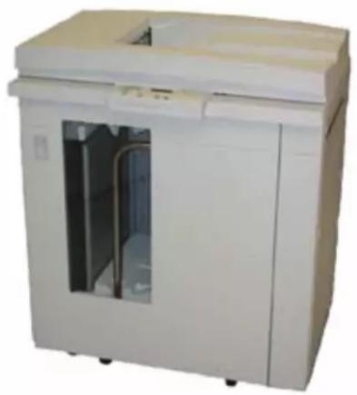
The DocuColor 5000AP is a full color/black and white digital press operating at a speed of fifty prints per minute. This chapter includes the following information:
• Identifying the digital press components, their names, locations, and functions
• Identifying the User Interface, its various components, and briefly discussing their functions

NOTE: The UI screens shown in this guide here may or may not reflect the UI screens displayed on your system. The UI screens vary from system to system and from marketplace to marketplace. Therefore, the UI screens in this guide here are a representation of the type of screens that may be seen on your particular system.
Identifying the digital press components
External components
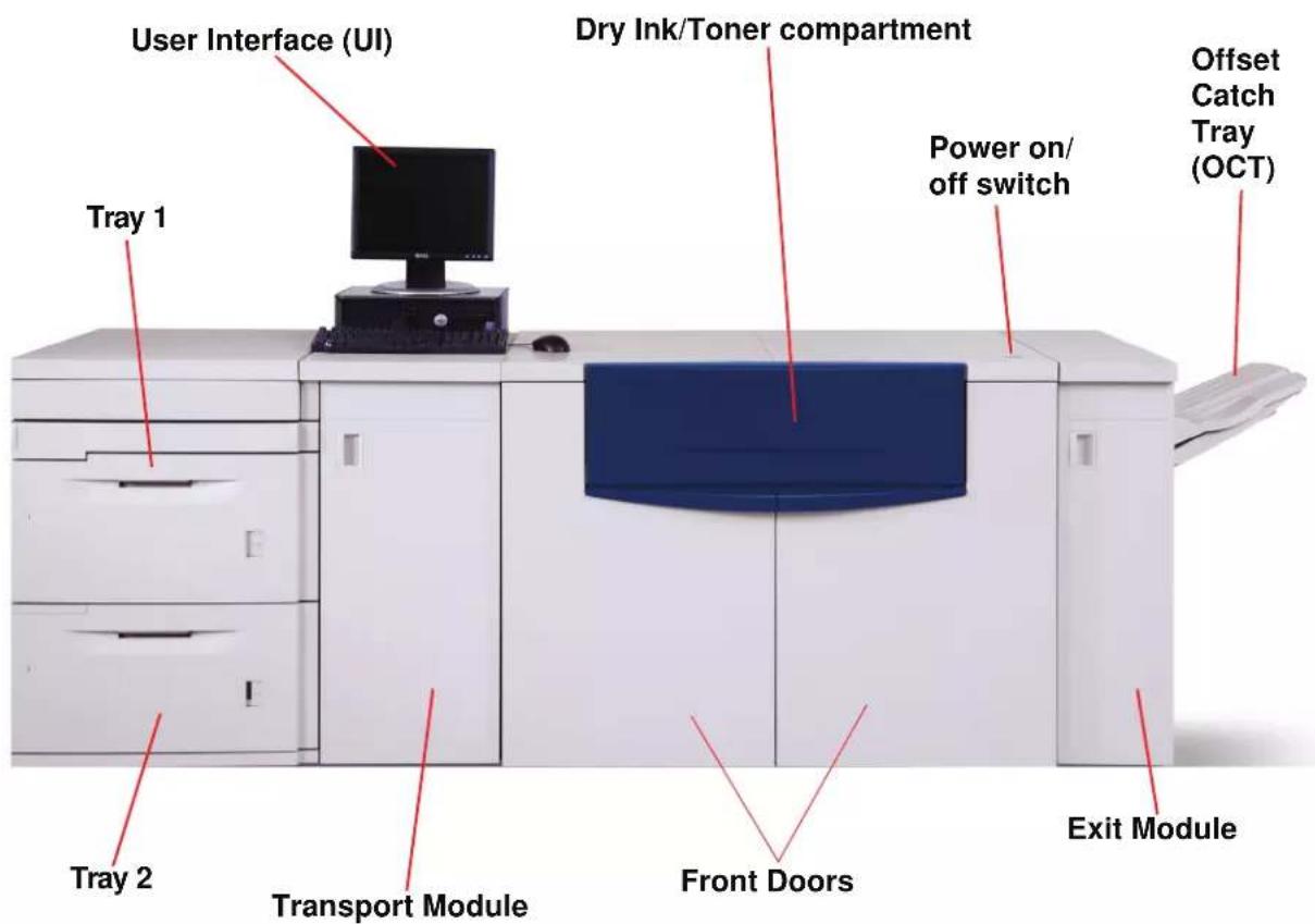
Use the illustration below and the following table to identify the external components that comprise the DocuColor 5000AP system.
text_image
User Interface (UI) Dry Ink/Toner compartment Tray 1 Power on/ off switch Offset Catch Tray (OCT) Tray 2 Transport Module Front Doors Exit Module
NOTE: The illustration above may or may not reflect the PC that is delivered with your machine. This illustration is only a representation of the type of PC that may come with your machine.
| Part Description | |
| User Interface | The User Interface (UI) displays messages that indicate the status of the digital press during idle, run, or fault conditions. For more detailed information, go to page 1-10. |
| Dry Ink/Toner Compartment | Contains the Dry Ink/Toner cartridges. The cartridge colors from left to right, are black, cyan, magenta, and yellow. Refer to page 7-11 for instructions on changing the cartridges. |
| Power On/Off switchOnOff | Press the Power Switch to theOnposition to power on the digital press. A screen message advises of a short wait while the Fuser warms up and the digital press runs a system check.Press the Power Switch to theOffposition to power off the digital press. Allow the digital press to remain off for a minimum of twenty seconds before switching the power on again. |
| Offset Catch Tray (OCT) | Receives completed print job. Sets are offset for easy separation.Maximum capacity is 500 sheets of 24 lb. (90 g/m2) paper.Optional finishing devices are discussed in Chapter 4 Accessories, starting on page 4-5. |
| Exit Module | Contains the decurler and the inverter. The decurler removes any curl from the printed page. The inverter is used when duplexing or face down output is selected. For more information go to page 1-9. |
| Right/Left Front Doors | Houses the image transfer system for simplex and duplex printing. Open to clear jams in the paper path in the Printing Module and at the Fuser. Follow the instructions on the UI precisely for clearing a jam in the Fuser.WARNING:The Fuser is extremely hot and will cause injury if jam clearing instructions are not followed. |
| Transport Module | The Transport Module carries the paper from the paper trays to the upper paper path of the digital press. It also routes the paper from the lower paper path of the digital press to the upper paper path of the digital press when duplexing. For more information go to page 1-7. |
| Paper Tray 1 | Holds 2000 sheets of 24 lb. (90 g/m2) paper. |
| Paper Tray 2 | Holds 2000 sheets of 24 lb. (90 g/m2) paper. |
Paper trays 1 and 2
Paper Trays 1 and 2 are the standard paper trays for the basic configuration of the digital press. Each tray holds 2000 sheets of 24 lb. (90 g/m ^2 ) paper.
Duplexing The digital press duplexes prints from all paper trays up to 220 g/ m². The system does not duplex media larger than 12.6 x 18 inch (321.1 x 458.1 mm).
Optional paper trays An optional Second Feeder Module (SFM) containing Trays 3 and 4 is available for as an additional paper source. The optional SFM is discussed in more detail in Chapter 4 Accessories, page 4-1.
Other external components
Dry Ink/Toner Waste Bottle
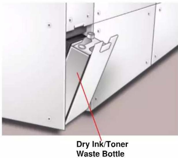
The Dry Ink/Toner Waste Bottle collects the waste dry ink/toner in the printing process. The Dry Ink/Toner Waste Bottle is customer replaceable and located in the rear of the machine.
text_image
Dry Ink/Toner Waste BottleRefer to Chapter 7 for instructions on changing the Dry Ink/Toner Waste Bottle.
Ground Fault Indicator (GFI) circuit breakers
The digital press is equipped with two safety circuit breakers called a Ground Fault Indicators (GFI). These devices trip if the power to the digital press is interrupted.

text_image
Rear of machine Fuser GFI (15 amp) Digital Press and SFM GFI (24 amp) Dry Ink/Toner Waste BottleFuser GFI The Fuser receives power through the Fuser GFI.
Digital Press GFI The digital press receives power through the Digital Press GFI. If an optional Second Feeder Module is connected to the Digital Press, then it too receives power from this GFI.
After a power outage occurs:
Power on the digital press as soon as possible after the power is restored, and print a job to ensure that there is no damage to the digital press.
If power to the digital press is interrupted,
- Locate the circuit breakers on the back of the digital press next to the toner waste bottle.
- If either device is tripped, the switch is in the Off position (down). Flip the switch up.

NOTE: If the device trips again or if power is not restored by the above procedure, call your Xerox service representative.
Identifying the internal components

flowchart
graph TD
    A["Dry Ink/Toner Cartridges (5)"] --> B["Paper Transport Drawer"]
    B --> C["Serial Number Label"]
    C --> D["Exit Module"]
    E["Transport Module"] --> B
Serial number label
If the digital press loses power and it is impossible to access the Machine Details tab for the serial number, open the two main front doors. The serial number label is in the center of the bottom frame of the digital press.
Dry Ink/Toner Cartridges
text_image
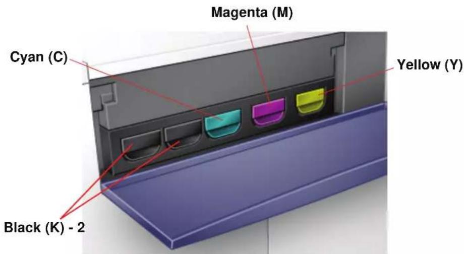
Magenta (M) Cyan (C) Yellow (Y) Black (K) - 2There are five Dry Ink/Toner Cartridges: Two Black (2) and one each for Cyan (C), Magenta (M), and Yellow (Y).
The toner cartridges supply a mix of toner and developer to their respective drum cartridges. There are two Black (K) cartridges because black requires more toner since black is the most heavily used color.
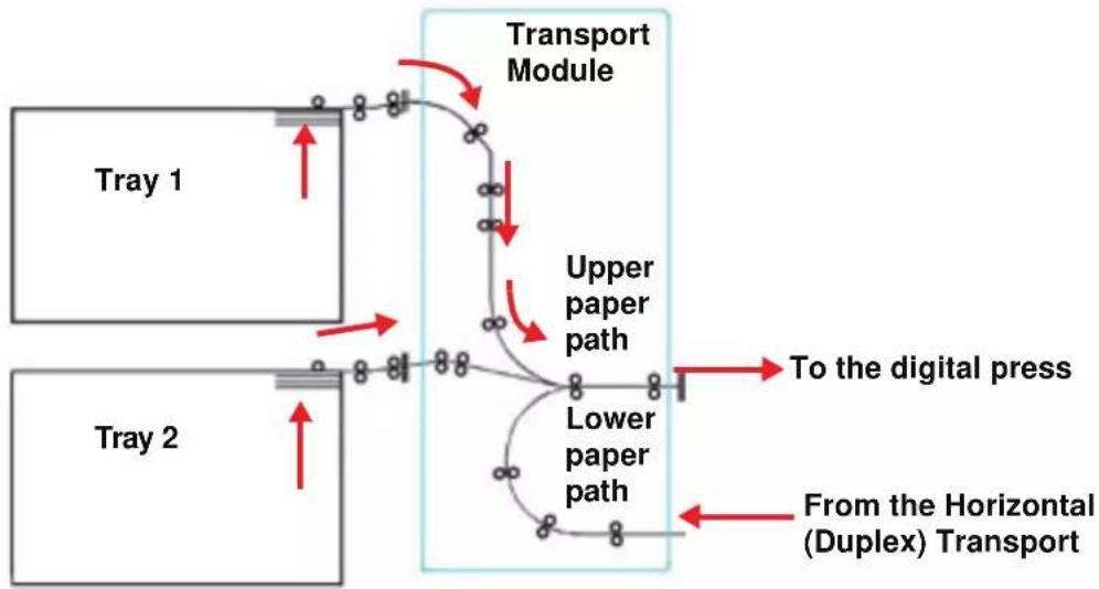
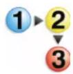
Transport Module
natural_image
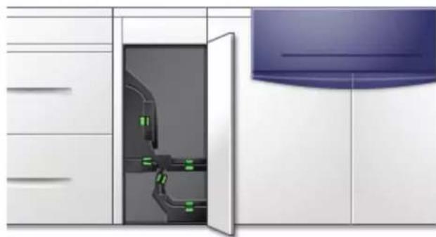
Interior view of a kitchen appliance with a door open, showing internal components and a blue ceiling (no text or symbols visible)The Transport Module carries the paper from the paper trays to the upper paper path of the digital press. It also routes the paper from the lower paper path of the digital press to the upper paper path of the digital press when duplexing.
Paper from all trays moves through the Transport Module to the upper paper path in the digital press. The lower paper path carries duplexed (2-sided) sheets through the Transport Module to the digital press upper paper path.
flowchart
graph TD
    A["Tray 1"] --> B["Upper paper path"]
    C["Tray 2"] --> D["Lower paper path"]
    B --> E["To the digital press"]
    D --> F["From the Horizontal (Duplex) Transport"]
    style A fill:#f9f,stroke:#333
    style C fill:#f9f,stroke:#333
    style B fill:#ccf,stroke:#333
    style D fill:#ccf,stroke:#333
    style E fill:#dfd,stroke:#333
    style F fill:#dfd,stroke:#333
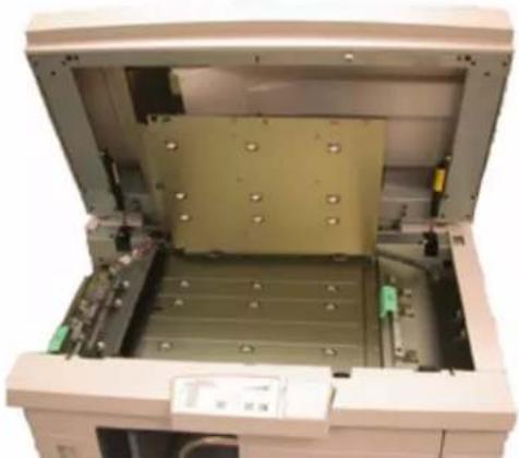
Paper Transport Drawer
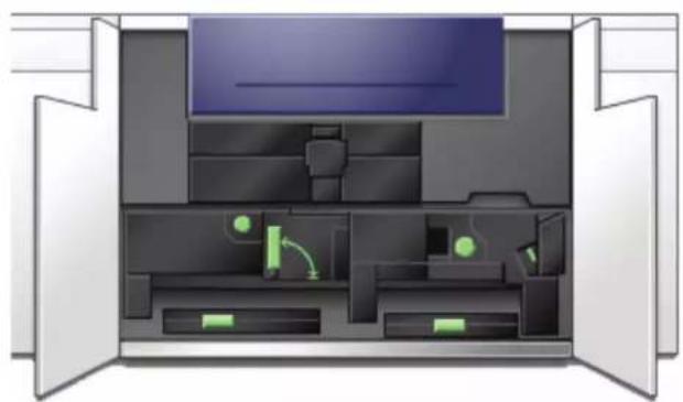
natural_image
Interior view of a computer room with open doors and internal compartments (no visible text or symbols)This area is where paper is aligned, the image is applied and fused, and the paper is flipped over if duplexing is required.
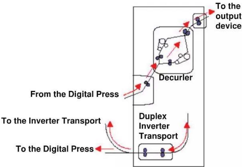
Exit Module
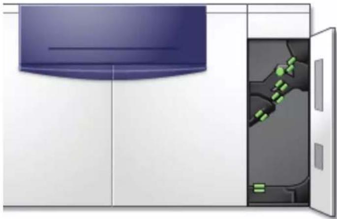
natural_image
Illustration of a kitchen appliance with a door open, showing interior and exterior views (no text or symbols)A completed print passes through the Exit Module to the Offset Catch Tray or other finishing device. The Exit Module contains a Decurler that removes paper curl caused by the fusing process. The Exit Module also contains an Inverter which turns the paper over to image side two when duplexing, or when face down output is selected.
flowchart
graph TD
    A["From the Digital Press"] --> B["Decycler"]
    B --> C["To the output device"]
    D["To the Inverter Transport"] --> E["Duplex Inverter Transport"]
    E --> F["To the Digital Press"]
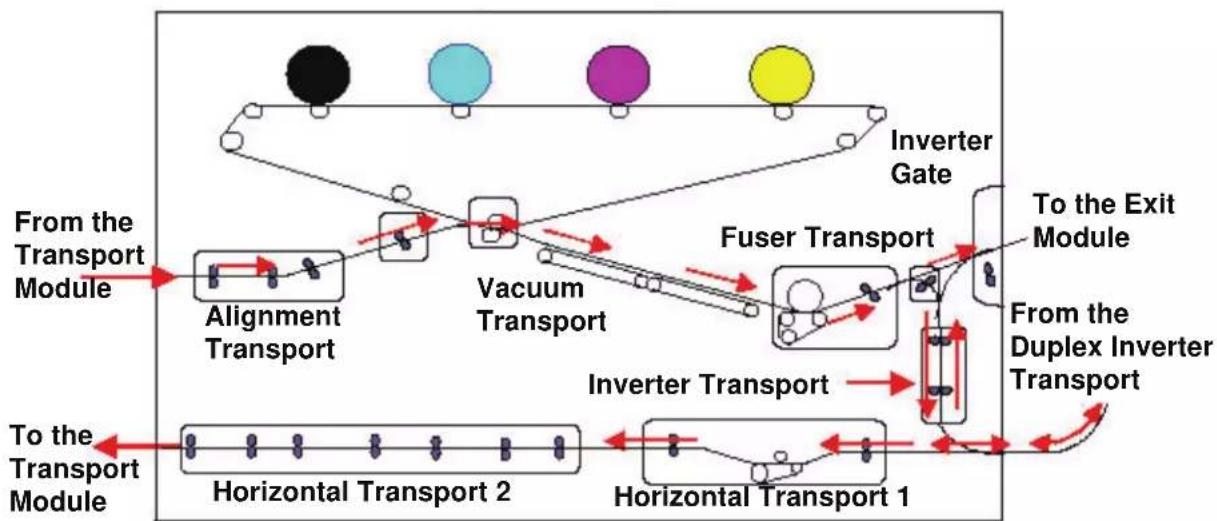
Paper path in the digital press
The paper path transfers an image to the paper and fuses it for both the simplex and duplex selections. It has two areas, the upper paper path and the lower paper path. The upper path is used for both simplexing and duplexing. The lower path is used for duplexing only. The Horizontal Transport 1 decurls the paper when printing duplex.
flowchart
graph TD
    A["From the Transport Module"] --> B["Alignment Transport"]
    B --> C["Vacuum Transport"]
    C --> D["Fuser Transport"]
    D --> E["To the Exit Module"]
    E --> F["From the Duplex Inverter Transport"]
    F --> G["Horizontal Transport 1"]
    G --> H["Horizontal Transport 2"]
    H --> I["Horizontal Transport 1"]
    I --> J["Inverter Transport"]
    J --> K["Inverter Gate"]
    K --> L["Output"]
User Interface (UI)
The User Interface (UI) displays messages that indicate the status of the digital press during idle, run, or fault conditions.

natural_image
Computer desktop setup with monitor, tower, keyboard, and mouse (no visible text or labels)NOTE: The illustration above may or may not reflect the PC that is delivered with your machine. This illustration is only a representation of the type of PC that may come with your machine.
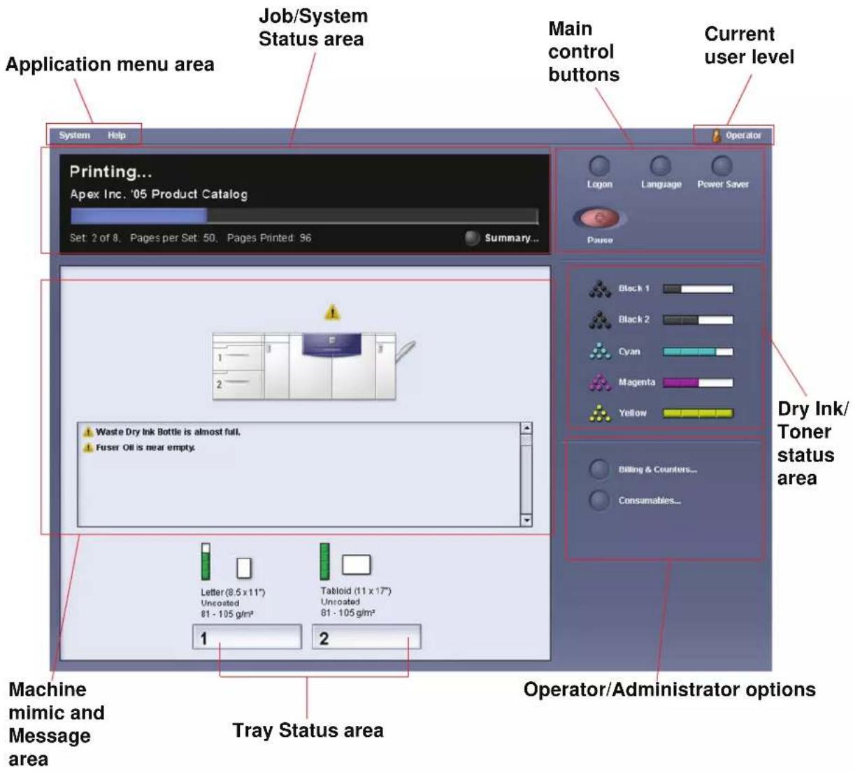
The default, main screen shown on the UI is shown in the illustration below.
text_image
Application menu area Job/System Status area Main control buttons Current user level System Help Printing... Apex Inc. '05 Product Catalog Set: 2 of 8, Pages per Set: 50, Pages Printed: 96 Summary... Operator Logon Language Power Saver Pause Dry Ink/ Toner status area 1 2 Waste Dry Ink Bottle is almost full. Fuser Oil is near empty. Letter (8.5 x 11") Uncosted 81 - 105 g/m² Tablet (11 x 17") Uncosted 81 - 105 g/m² 1 2 Tray Status area Machine mimic and Message area Operator/Administrator optionsApplication menu area
This area of the main screen is comprised of two pull-down menus: System and Help.
System menu
The System pull-down menu allows you to select the following options:
- Machine Details: By selecting this option, a Machine Details window opens. Refer to "Machine Details" on page 1-14 for more information on this feature.
- Shutdown System PC: This option shuts down the User Interface and the system PC.
- Restart User Interface: This option stops and exits the User Interface and then restarts it.
- Exit User Interface: This option exits the User Interface but leaves the System PC running.
An additional feature may be selected when the machine is configured for it:
- Finishing System Module: This option is available only if an optional finishing device is attached to your system. If an optional finishing device is attached and you are logged in as the Administrator, then this feature is available from the pull-down menu.
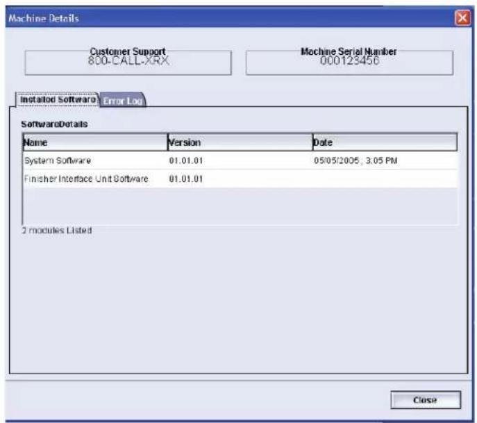
Machine Details
Selecting the Machine Details feature from the System pull-down menu displays the following window.
text_image
Machine Details Customer Support 800-CALL-XRX Machine Serial Number 000123456 Installed Software Error Log SoftwareDetails Name Version Data System Software 01.01.01 05/05/2005, 3:05 PM Finisher Interface Unit Software 01.01.01 2 modules Listed CloseThe Machine Details window provides specific information about your machine, such as:
- Customer Support telephone number
• Machine Serial Number
- Installed Software: This tab displays a list of installed software, version level, and date of installation. This tab also displays a list of any installed optional finishing devices.
- Error Log: This tab displays a list of all the machine errors, fault ID number, and date the error occurred.
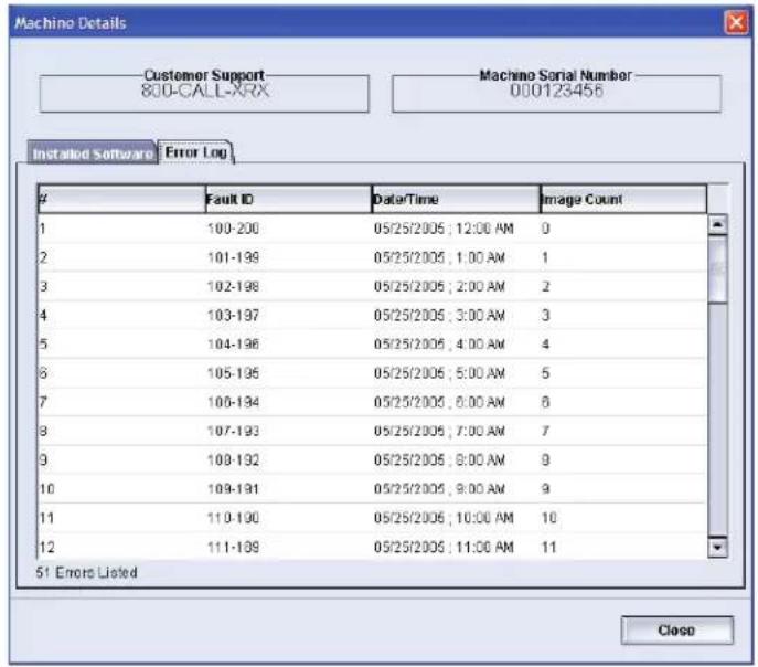
text_image
Machino Details Customer Support 800-CALL-XRX Machino Serial Number 000123456 Installed Software Error LogFault ID Date/Time Image Count
1 100-200 05/25/2005 ; 12:00 AM 0 2 101-199 05/25/2005 ; 1:00 AM 1 3 102-198 05/25/2005 ; 2:00 AM 2 4 103-197 05/25/2005 ; 3:00 AM 3 5 104-196 05/25/2005 ; 4:00 AM 4 6 105-195 05/25/2005 ; 5:00 AM 5 7 106-194 05/25/2005 ; 6:00 AM 6 8 107-193 05/25/2005 ; 7:00 AM 7 9 108-192 05/25/2005 ; 8:00 AM 8 10 109-191 05/25/2005 ; 9:00 AM 9 11 110-190 05/25/2005 ; 10:00 AM 10 12 111-189 05/25/2005 ; 11:00 AM 11 5! Errors Listed CloseHelp menu
Selecting DocuColor 5000AP from the Help pull-down menu opens a new window displaying the following type of information:
• An overview of the digital press and UI
• Paper tray information, including:
• Paper specifications
- Paper guidelines
- Loading paper
- Changing paper sizes in the trays
• Information about the various optional accessories
• Problem solving information
- Technical data
- Maintenance information, including:
- Cleaning procedures
- Replacing Customer Replaceable Units (CRUs) procedures
• Administrator information:
- An overview of Administrator features, including:
- System Settings
– Custom Paper Profiles - Decurler
- Alignment Profiles
- Step-by-step procedures for the Administrator features
Job/System Status area

text_image
System Help Printing... Apex Inc. '05 Product Catalog Set: 2 of 8, Pages per Set: 50, Pages Printed: 96 Summary...This area of the screen displays the status of the system, such as Ready, Waiting for print, Powering up, Powering down, etc. This area also displays the status of any currently printing job.
Job Summary
Selecting Summary button opens the Current Job Summary window:
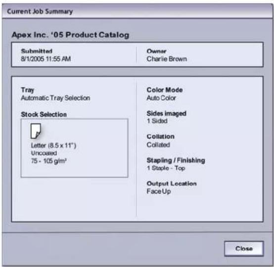
text_image
Current Job Summary Apex Inc. '05 Product Catalog Submitted 8/1/2005 11:55 AM Owner Charlie Brown Tray Automatic Tray Selection Stock Selection Letter (8.5 x 11") Uncoated 75 - 105 g/m³ Color Mode Auto Color Sides Imaged 1 Sided Collation Collated Stapling / Finishing 1 Staple - Top Output Location Face Up CloseMachine mimic and Message area
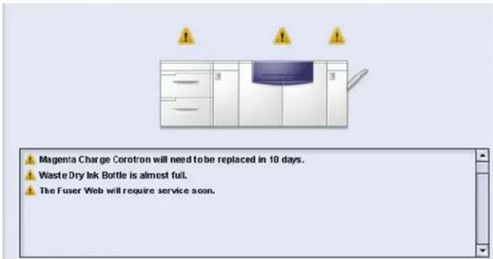
text_image
Magenta Charge Corotron will need to be replaced in 10 days. Waste Dry Ink Bottle is almost full. The Fuser Web will require service soon.This area displays information about the machine including:
- The status of various machine components, such as the Dry Ink/Toner and Fuser Web,
- Alerts when a Customer Replaceable Unit (CRU) component needs replacement, or
- Warnings and faults
TIP: The UI automatically opens a Details window which provides additional information about the alert, warning, or fault. The information on this Details window provides step-bystep instructions and assists you in restoring the machine to normal performance. If this window does not automatically open, you may click on the alert, warning, or fault, thereby opening the window.

text_image
Click to open the Details window System Fault: 2-311 The system has encountered a problem and needs to be shutdown and then restarted. Use the Power Switch to turn off the power to the machine. Wait at least five seconds and then turn the power back on. If this fault message reappears, please record the System Fault number (2-311) and call your Xerox Customer Support Center.NOTE: The automatically opening of this Details window can be changed. For more information, refer to Chapter 2 of the Administrator Guide.
Tray status area

text_image
Letter (8.5 x 11") Uncoated 106 - 135 g/m² Letter (8.5 x 11") Uncoated 106 - 135 g/m² 1 2Click to open the Tray Properties window
This area of the UI displays the paper trays and their status, including which tray is currently in use during a print job. The number of paper trays shown depends on your machine's configuration.
By clicking on a tray button, the Tray Properties window opens. Refer to Chapter 2 Tray Properties for more information on this feature.
Main control buttons
Logon and current User level
There are two logon levels:
- Operator: This is the default logon level.
- Administrator: This level allows you to customize the system defaults for your machine. This level also allows you to customize particular print jobs by creating, setting, or changing parameters for certain features.
Refer to Chapter 1 of the Administrator Guide for more information on this feature.
Current User Level
The current User Level is displayed on the upper right side of the UI screen:

text_image
Operator Logon Language Power Saver Pause User LevelLanguage
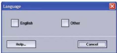
text_image
Language English Other Help... CancelThe Language window changes the language on the UI. The UI is capable of storing a maximum of eight (8) languages, all of which are simultaneously available upon the user's request.

NOTE: The number of languages available on your system depends on what was installed during the initial installation process.
Selecting a particular Language button immediately changes the language. No confirmation is required.
If fewer than eight languages are available on your UI, the position of the buttons change accordingly.
To change the language, use the following procedure.
- Select the Language button on the UI.
- Select the desired language button; the language on the UI changes to the new language and closes the Language window.
- Select the Cancel button to return to the main UI screen.
Power Saver
text_image
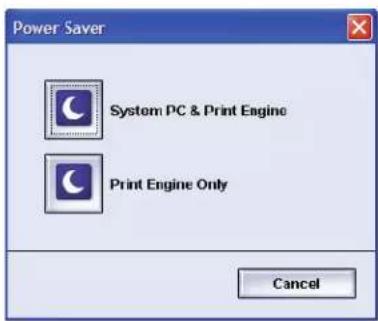
Power Saver System PC & Print Engine Print Engine Only CancelPressing the Power Saver button displays the Power Saver screen. There are two Power Saver modes:
- System PC & Print Engine: Selecting this option places both the digital press and the System PC in power saver mode.
- Print Engine Only: Selecting this option places only the digital press in power saver mode.
The Power Saver mode reduces power consumption mode during which the Fuser temperature is lowered. The digital press automatically goes into this mode after no activity occurs for the factory default time of fifteen minutes. This time can be changed to reflect a value of 1-240 minutes; you must enter the Administrator mode to change it.
The digital press and/or System PC exits the Power Saver mode when a job is sent to be printed or the UI on the System PC is activated.
NOTE: To manually exit Power Saver mode, press the Power Saver button on the System PC.
Refer to the Power Saver section in Chapter 2 of the Administrator Guide for more information on this feature.
Pause
text_image
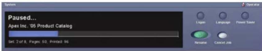
Paused... Apex Inc. '05 Product Catalog Set 2 of 8, Pages: 50, Printed: 96 Logan Language Power Save Rename Cancel JobSelecting the Pause button during a print job stops or pauses the printing process. Once a print job is paused, you may choose either:
- Resume: Selecting this option resumes the print job from the point it was paused.
- Cancel Job: Selecting this option displays a secondary window asking the user if they want to cancel the print job.
- Selecting Yes cancels the printing process.
- Selecting No closes the Confirm Cancel Job window and returns the machine to the paused state. You must select Resume to continue the printing process.

NOTE: Depending on the Administrator setting, your machine may automatically resume printing after a preset period of time without selecting the Resume button. Ask your Administrator about this or refer to Chapter 2 of the Administrator Guide for more information.
Dry Ink/Toner status area

text_image
Black 1 Black 2 Cyan Magenta YellowThis area of the UI displays the status of the dry ink/toner cartridges with a gauge indicating the level/amount of toner for each cartridge. As toner is used, the display continually updates the gauge for each toner cartridge.
For example, the gauges for the dry ink/toner cartridges indicate the amount of toner in each cartridge:
- The cartridge is 100 % full when all four bars are filled with its appropriate color (as indicated in the illustration with Yellow).
• The cartridge is 75% full when three bars filled (as shown with Cyan).
- The cartridge is 50 % full when two bars are filled in (as shown with Magenta and Black 2).
• The cartridge 25% full when one bar is filled in (as shown with Black 1).
The five dry ink/toner cartridges are Customer Replaceable Units (CRUs). Each cartridge is also equipped with a CRUM (Customer Replaceable Unit Memory) monitor. The CRUM is a wireless system that monitors and stores information about the dry ink/toner cartridges, including the following:
- Characteristics of the dry ink/toner cartridges which guarantee the number of prints described in the user specifications
• Information that guarantees image quality
• Information which allows it to detect the life span of each cartridge - Maintaining a usage log for each color for reference at the time of collection by the customer and the service representative
- Preventing erroneous insertion of a different dry ink/toner cartridge
- Managing the number of times cartridge is removed and reinstalled, and finally
- Detecting the replacement of a used cartridge with a new one
Operator/Administrator buttons

text_image
Billing & Counters... Consumables... Logged on as Operator
text_image
Billing & Counters... Consumables... Profiles... System Settings... Logged on as AdministratorThis area of the UI displays the Operator/Administrator buttons. Depending on the current user status, the features shown here will vary:
- If you are logged on as Operator, these features are available:
- Billing & Counters
- Consumables
- If you are logged on as Administrator, in addition to Billing & Counters and Consumables, these features are also available:
- Profiles
- System Settings

NOTE: Refer to Chapter 2 System Settings and Chapter 3 Profiles of the Administrator Guide for more detailed information on System Settings and Profiles.
Billing & Counters
text_image
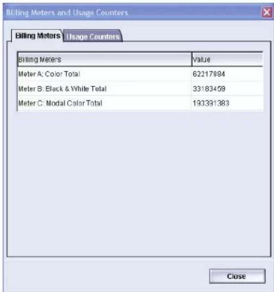
Billing Meters Usage Counters Billing Meters Value Meter A: Color Total 62217884 Meter B: Black & While Total 33183459 Meter C: Modal Color Total 193391383 CloseThis screen displays the Billing Meters and Usage Counters information:
- The Billing Meters screen keeps track of total number of prints, and the information displayed may vary from market place to market place. These meters cannot be reset.
- The Usage Counter screen works the same way as a trip odometer in a car. It can be reset to zero. Once it is reset to zero, it keeps track of the print count from that point forward until you select the Reset All button.
The information displayed on this screen may vary from market place to market place.
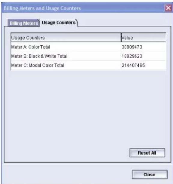
text_image
Billing Meters and Usage Counters Billing Meters Usage Counters Usage Counters Value Meter A: Color Total 30809473 Meter B: Black & White Total 16829623 Meter C: Modal Color Total 214407465 Reset All CloseTo reset the meters to zero, select the Reset All button.
Consumables

text_image
Billing & Couriers... Consumables... Profiles... System Settings...Selecting the Consumables button opens a window which displays a status of each consumable. The Consumables screen is divided into two sections as shown in the following illustration:
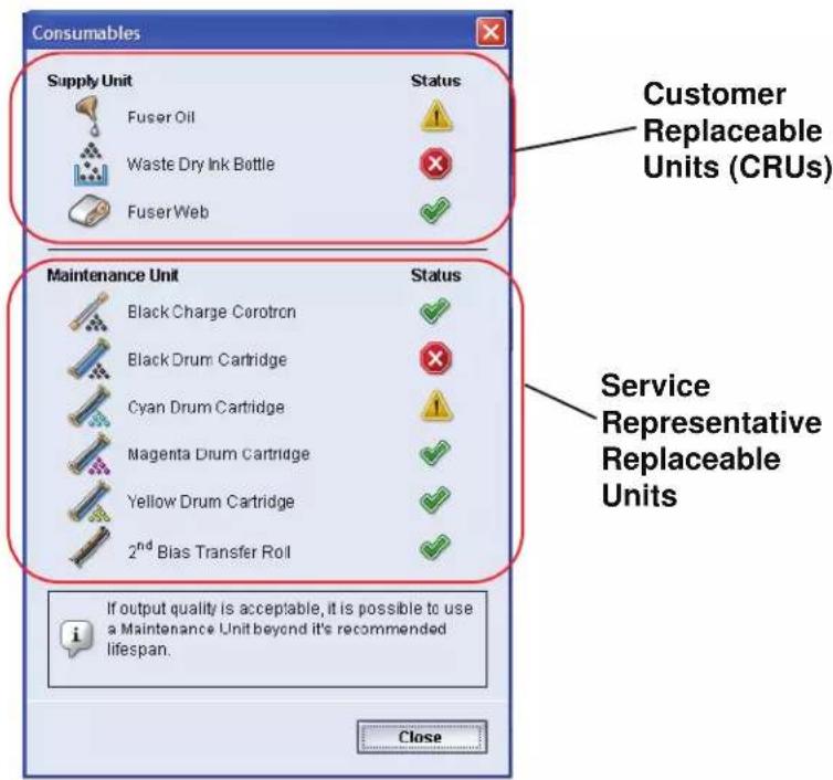
text_image
Consumables Supply Unit Status Fuser Oil Waste Dry Ink Bottle Fuser Web Customer Replaceable Units (CRUs) Maintenance Unit Status Black Charge Corotron Black Drum Cartridge Cyan Drum Cartridge Magenta Drum Cartridge Yellow Drum Cartridge 2ndBias Transfer Roll Service Representative Replaceable Units If output quality is acceptable, it is possible to use a Maintenance Unit beyond it's recommended lifespan. CloseThe status of a consumable is represented by:
- A yellow triangle ( ) indicating that the level is low
- A red circle () indicating that the consumable is depleted or at its limit
- A green check mark () indicating that the level of the consumable is adequate

NOTE: When a Customer Replaceable Unit (CRU) consumable item is depleted, the digital press automatically interrupts the current job and does not restart until the consumable is replaced.

TIP: The digital press does not interrupt a job or stop running if a Service Representative Replaceable Unit status indicates a low or depleted level. Your Service Representative Replaceable Unit may continue to perform as expected far beyond the average life indicator. Your Service Representative uses this status indicator information each time service is performed on your machine.
Administrator buttons
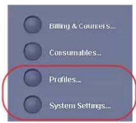
text_image
Billing & Couriers... Consumables... Profiles... System Settings...If you are logged as Administrator, the Profiles and System Settings features are available to you.
- The Profiles feature allows you to create customized procedures for your work/printing environment. These customized procedures include Alignment, Custom Paper, and Decurler.
Refer to Chapter 3, Profiles in the Administrator Guide for more detailed information on each of the Profiles features.
- The System Settings feature allows you to make changes to the following:
- User Interface
- Date and Time
- System
- Tray Options
Refer to Chapter 2 System Settings in the Administrator Guide for more detailed information on each of the System Settings features.
Relocating the digital press
If you need to relocate the digital press, call your Xerox customer representative. The Installation Planning procedure must be conducted for every new site.
Customer documentation updates
You can get the latest customer documentation and information for your product by going to www.xerox.com and doing one of the following:
- Enter your product number (e.g., DocuColor 5000) in the Search field and select Search.
- Select the Support & Drivers link and then use the search options to locate your specific printer.
Be sure to periodically check www.xerox.com for the latest information for your product.
2. Tray Properties
Overview
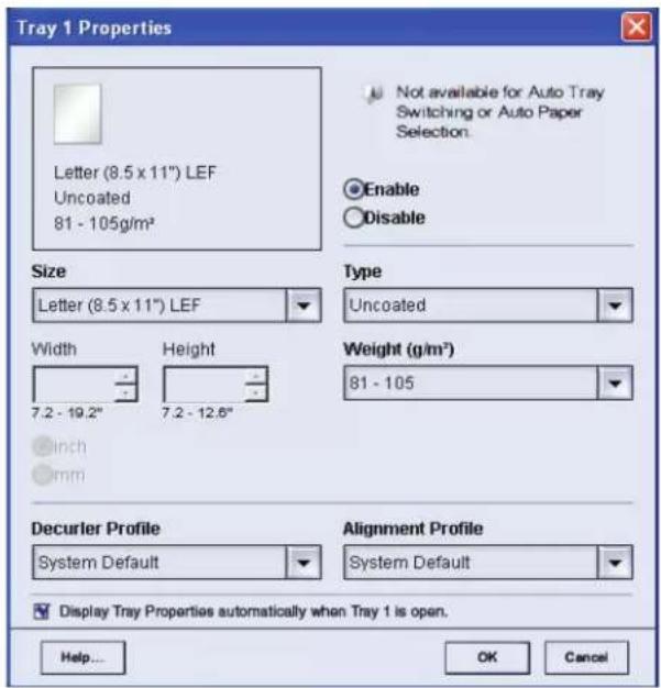
The Tray Properties window allows you to set the parameters for the paper that is loaded in the tray.
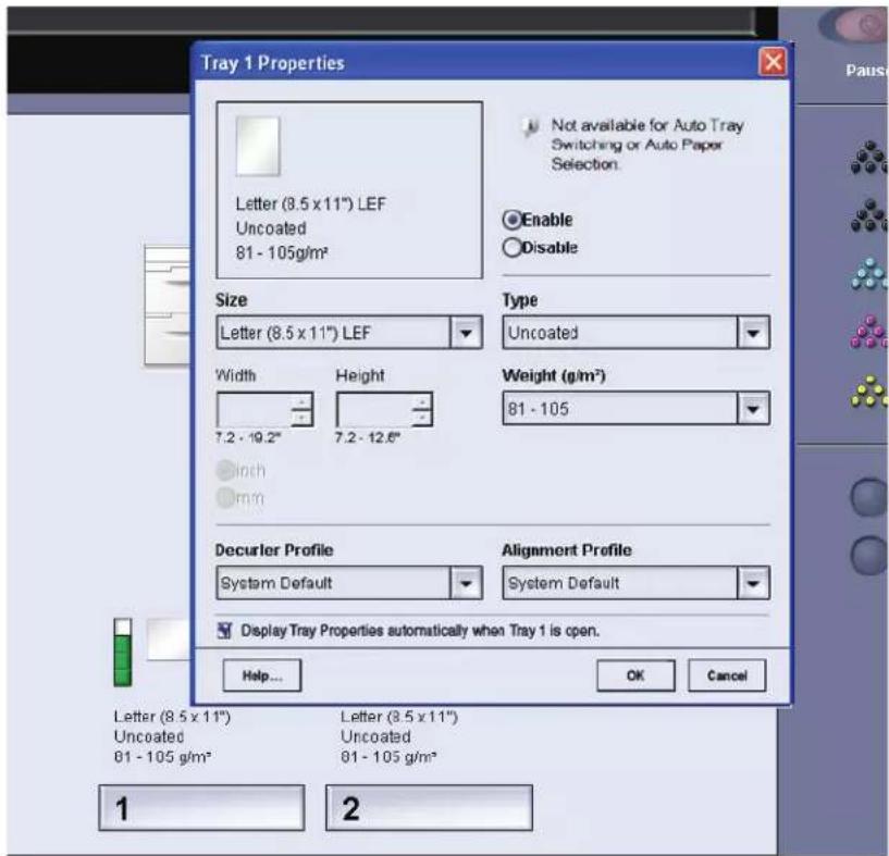
text_image
Tray 1 Properties Letter (8.5 x 11") LEF Uncoated 81 - 105g/m² Not available for Auto Tray Switching or Auto Paper Selection. Enable Disable Size Letter (8.5 x 11") LEF Type Uncoated Width Height 7.2 - 19.2" 7.2 - 12.6" Weight (g/m²) 81 - 105 Inch mm Decurler Profile System Default Alignment Profile System Default Display Tray Properties automatically when Tray 1 is open. Help... OK Cancel Letter (8.5 x 11") Letter (8.5 x 11") Uncoated Uncoated 81 - 105 g/m² 81 - 105 g/m² 1 2Tray Properties window
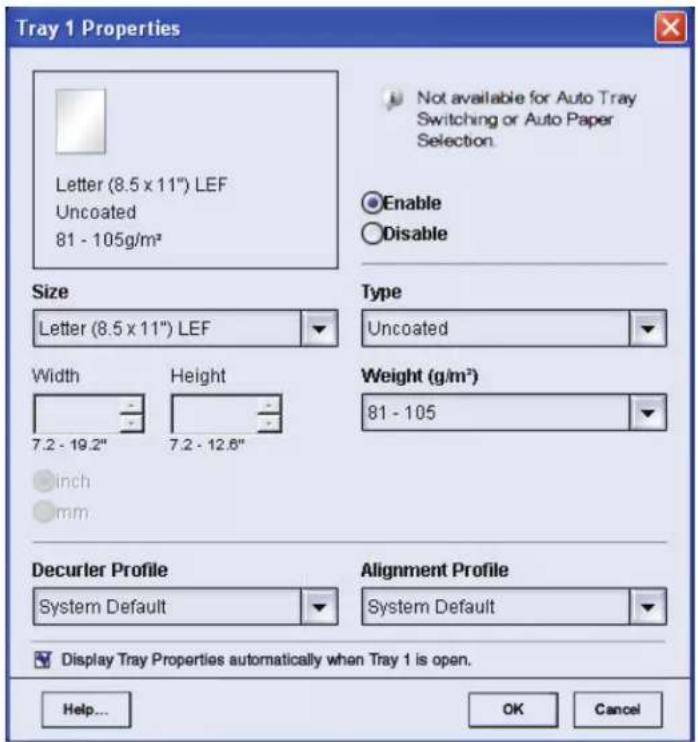
text_image
Tray 1 Properties Letter (8.5 x 11") LEF Uncoated 81 - 105g/m² Not available for Auto Tray Switching or Auto Paper Selection. Enable Disable Size Letter (8.5 x 11") LEF Width 7.2 - 19.2" Height 7.2 - 12.6" inch mm Type Uncoated Weight (g/m²) 81 - 105 Decurler Profile System Default Alignment Profile System Default Display Tray Properties automatically when Tray 1 is open. Help... OK CancelFrom the Tray Properties window you can make various paper selections, such as size or customer size (width and height), type, weight, and more. Each area of the Tray Properties screen is discussed in more detail on the following pages.
Current tray information

text_image
Letter (8.5 x 11") Uncoated 81 - 105 g/m²This area of the Tray Properties screen displays the current tray information including the paper size, type, weight, and orientation of the paper (LEF or SEF).
Not available for...

Not available for Auto Tray Switching or Auto Paper Selection.
This area of the screen displays whether a tray is available for Auto Tray Switching (ATS) or Auto Paper Selection (APS). The tray's availability for either of these features is determined in System Settings.
Auto Tray Switching
When Auto Tray Switching (ATS) is activated in the System Settings of the Administrator mode, the digital press automatically switches to another tray containing paper of the identical size, weight, type, and feeding orientation (SEF or LEF) when the tray being used is empty.
Auto Paper Selection
Auto Paper Selection (APS) can be enabled in the System Settings of the Administrator mode. When enabled, the digital press automatically selects the paper tray containing the correct size paper without a specific paper tray being selected.
Refer to the Administrator Guide for more information on ATS and APS.
Enable/Disable

Enable

Disable
This area of the screen allows you to enable or disable a specific tray for use. If Enable is selected, the paper tray is available for use by the machine. If Disable is selected, the paper tray is disabled and is not available for use by the machine.
Size

text_image
Size Letter (8.5 x 11") Width Height 7.2 - 19.2" 7.2 - 12.6" ● Inch ○ mmThis area of the screen displays the size of the paper that is currently loaded in the tray. The information shown here includes the width and height of the paper and/or any custom paper size information. You can select a different paper size from the pull-down menu.
Custom Paper Size
You can run custom (nonstandard) sized paper from any paper tray by selecting Custom from the Size pull-down menu and entering the specific paper size information for the tray being used.
Type
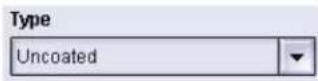
This area displays the type of paper that is currently loaded in the tray. You can select a different type from the pull-down menu.

NOTE: If one or more Custom Paper Profiles have been created, these profiles are available for selection from this pull-down menu. Refer to the Administrator Guide for more information on Custom Paper Profiles.
Weight

This area of the screen displays the weight of the paper currently loaded in the tray. You can change the weight from the pull-down menu. If custom paper profiles have been created, these profiles are listed and accessible for selection from the pull-down menu.
Decurler Profile

This area of the screen allows you to select a specific Decurler profile or the system default from the pull-down menu.
Your system is designed with several automated settings to control curl. When using these settings the machine automatically sends paper through the proper Decurler:
- System Default: Automatically determines the amount of pressure needed at the different Decurlers in order to reduce the output curl of the paper.
- A, B, C, and D settings: Preset Decurler settings, which are manually selected as an alternative to the System Default setting.
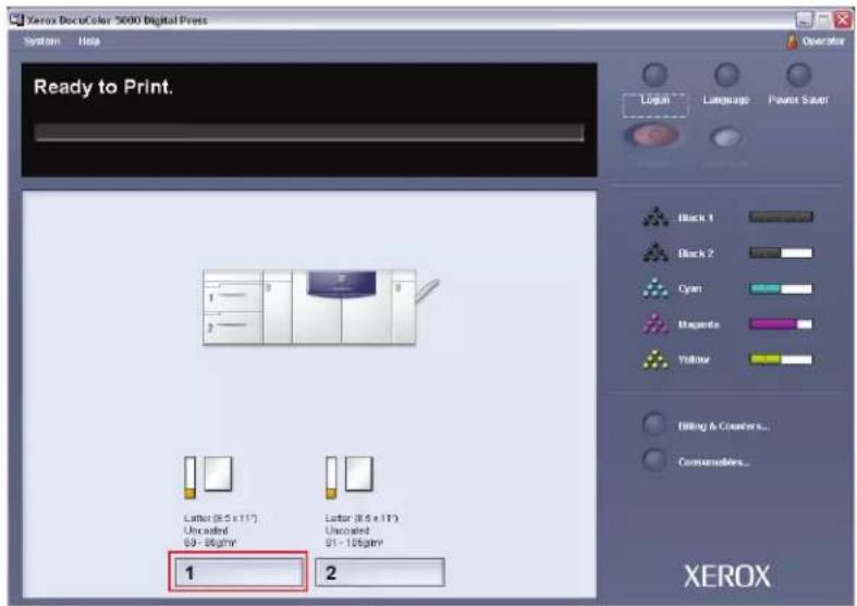
To select a Decurler Profile:
- Select the tray that contains the job stock, which requires curl control. For this exercise, select Tray 1.
text_image
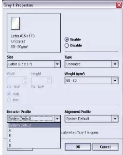
Xerox DecuColor 5000 Digital Press System Help Ready to Print. 1 2 Letter (8.5 x 117) Uncoiled 69 - 86g/m² Letter (8.5 x 117) Uncoiled 61 - 106g/m² 1 2 Operator Login Language Paint Saver Black 1 Black 2 Cyan Magnets Yellow Editing & Creaters... Consoliders... XEROX- From the Decurler Profile menu, select the Decurler Profile that you want to use and then select OK.
text_image
Tray 1 Properties Letter (0.5 x 11°) Uncosated 60 - 80 gm² Enable Disable Size Letter (8.5 x 11°) Width Height 7.2 - 10.2" 7.2 - 12.9" Inch mm Type Uncosated Weight (gm²) 60 - 80 Decurler Profile System Default System Default A B C D Alignment Profile System Default cally when Tray 1 is open. OK Cancel
NOTE: If a Decurler profile is changed, it remains at that setting until changed again manually. As an example, if you decide to use the B Decurler setting, the setting will remain at B until you change it to another setting.
NOTE: With some print jobs, the output prints still may be curled more than you desire even after using the Decurler A-D Settings. In those cases, use the Custom Decurler Profile feature to compensate for paper curl in your prints. For additional information on the Decurler and the step-by-step instructions on using it, Chapter 3 of the Administrator Guide, which is located on your Customer Documentation CD or at www.xerox.com.
Alignment Profile
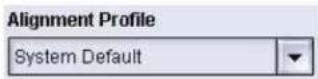
This area of the screen allows you to select a specific alignment profile or the system default from the pull-down menu.
Refer to the Administrator Guide for more detailed information on each of the Profiles features.
Display...

Display Tray Properties automatically when Tray 1 is open.
If this box is checked, the Tray Properties window opens whenever the tray is open.
Help button
Click the Help button to obtain more detailed information on the various Tray Properties features.
Selections made on the Tray Properties window
text_image
Tray 1 Properties Letter (8.5 x 11") LEF Uncoated 81 - 105g/m² Not available for Auto Tray Switching or Auto Paper Selection. Enable Disable Size Letter (8.5 x 11") LEF Width 7.2 - 19.2" Height 7.2 - 12.6" Inch mm Type Uncoated Weight (g/m²) 81 - 105 Decurler Profile System Default Alignment Profile System Default Display Tray Properties automatically when Tray 1 is open. Help... OK Cancel
TIP: Selections made to any of the Tray Properties features remain at those specific settings until changed again manually.
For example, if you decide to change the Decurler Profile setting from System Default to A (as shown in the following illustration), setting A remains in effect until you change it to another setting. This is important to remember when preparing your job for printing. Ensure that all your desired options are selected from the Tray Properties window before printing your job.

text_image
Tray 1 Properties Letter (8.5 x 11") LEF Uncoated 81 - 105g/m² Size Letter (8.5 x 11") LEF Width 7.2 - 19.2" Height 7.2 - 12.6" inch mm Type Uncoated Weight (g/m²) 81 - 105 Deculer Profile A Alignment Profile System Default Display Tray Properties automatically when Tray 1 is open. Help... OK Cancel Not available for Auto Tray Switching or Auto Paper Selection Enable DisableBasic paper information
Refer to Chapter 3 Paper information for basic paper information such as:
- Paper handling
• Paper guidelines, including:
• Paper specifications - Tabbed guidelines
• Transparency guidelines
• Paper weight conversion tables -
Loading paper in the paper trays
• Paper trays air adjustment -
Drilled paper guidelines for 1-sided and 2-sided print jobs
• Paper Tray Stock Mismatch information
3. Paper information
Recommended Materials List (RML)
Refer to the Recommended Materials List and the Speciality Media Guide: Hints and Tips for paper guidelines. The Recommended Materials List and the Speciality Media Guide: Hints and Tips documents are updated on an on-going basis to include new papers and other media. PDF files are available at www.xerox.com. Use the search parameter DocuColor 5000AP and follow the path until you reach the files to download.
Paper handling

NOTE: Many suppliers use arrows on the product labels to indicate the preferred side to image first. Use this side (as signaled by the arrow) as equivalent to the seam side when loading the paper.
Label on the ream instructs you to "Print arrow side first"
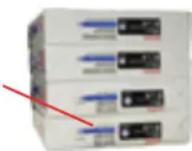
For the best performance, load paper with the seam side up in all the paper trays. The seam side is where the ream of paper is sealed. Refer to the label on the paper ream.
Many factors affect the performance of paper, including room temperature, humidity, paper quality, dust, and the size of the image area. If jams or paper curl problems occur, remove the paper from the paper tray, turn it over, place it back in the paper tray, and resume printing. If the problem is rectified, continue to load your paper in the same manner.
If the problem is not rectified, load a new ream of paper and try the process again. If the problem persists, your Administrator may go into the Administrator mode and try the different Decurler settings.

NOTE: Decurler Profile settings Default and A-D are available to the user. See, Chapter 2 Tray Properties for additional details. For additional information on the Decurler and the step-by-step instructions on using it, Chapter 3 of the Administrator Guide, which is located on your Customer Documentation CD, or at www.xerox.com.
If, after trying all the previous suggestions, the problem still persists, call your Xerox representative.
For reliable digital press operation and good print quality, Xerox recommends the following:
Stored paper: • On a flat surface. Do not store paper directly on the floor, since this increases the possibility of moisture absorption. Paper should be stored on pallets, shelves, or in cabinets in an area protected from extremes of temperature and humidity.
- In a low dust area.
- In a low humidity area. Humidity is one of the most important steps to promote proper paper characteristics. Optimum paper storage conditions include a relative humidity of 35 - 55% . An increase in humidity may cause paper to develop wavy edges. This occurs because the edges absorb moisture while the rest of the ream remains unaffected. Wavy edges causes jams and misfeeds.
- In an air-tight, moisture-proof container.
- In a controlled temperature. The temperature in the room where paper is stored has a significant effect on how that paper performs in the machine. Optimum paper storage temperature is 68 - 76^ (20-24.4°C).
Cutting and trimming paper
Proper cutting of the paper is important. Mills that offer paper in “cut sizes” crop their papers using state-of-the-art rotary slitters on high performance systems. Slitting and edge trimming by circular knives with dust removal at every cutting point prevents contamination of the paper.
Trimming papers from parent sheets to get the desired output size may generate dust if dull knives are used. The recommendation is to delay trimming until printing has been finalized to prevent paper dust generation and contamination.
If pre-printing is imperative, an in-house maintenance program, including knife sharpness maintenance and dust removal with a vacuum or air system, are key to achieving good results.
Paper guidelines
For the best results, remember the following:
- Do not load paper or other materials above the MAX line on the rear paper guide.
- Do not store extra reams of paper in the paper trays.
- Do not use wrinkled, torn, curled, or folded paper.
- Use the paper sizes and weights shown in the Recommended Materials List.
- Follow the suggestions in the Specialty Media Guide: Hints and Tips.
- Do not mix sizes or weights of paper in a paper tray.
- Ensure that the tray is set for the correct paper size, weight range, and paper type.

SEF LEF


Copy paper is fed into the digital press in one of two positions: long edge feed (LEF) or short edge feed (SEF). Long edge refers to the long edge of the paper. When you see LEF, position the paper so the long edge is fed first. Short edge refers to the short edge of the paper. When you see SEF, position the paper so the short edge is fed first.
NOTE: It is imperative that you load paper with the paper guides adjusted properly. If the paper is NOT loaded properly, it skews and jams occur.
Curl
When paper is exposed to heat, the paper loses moisture and curls toward the heat source. High toner coverage jobs tend to curl more than low toner coverage jobs. The system tries to reduce this by using mechanical devices within the paper path called Decurlers.
Paper curl is caused by many variables, including, but not in any particular order:
- The weight of the paper and whether it is coated or uncoated.
- The amount of dry ink/toner and the area being covered on a sheet: the heavier the coverage, the greater the tendency to curl.
- How the paper is loaded in the tray. Make sure you load the paper as instructed on the ream wrapper.
- The atmospheric conditions of the room where the paper is stored and where the printer is located, especially those related to humidity and temperature.
- The heat generated during the fusing processes.

NOTE: If the curl is excessive, use the Decurler Profile settings Default and A-D, which are available to the user. See, Chapter 2 Tray Properties for additional details. For additional information on the Decurler and the step-by-step instructions on using it, Chapter 3 of the Administrator Guide, which is located on your Customer Documentation CD, or at www.xerox.com
Paper specifications
| Paper All Paper Trays | ||
| Minimum Paper Size 182mm x 182mm | (7.2 x 7.2") | |
| Maximum Paper Size 320mm x 488mm | (12.6 x 19.2") | |
| Standard Sizes B5 LEF/SEF | B4 SEF8 x 10" LEF/SEF8.5 x 13" SEF11 x 17" SEF12.6 x 17.7" SEF^(1) SRA3" (320 mm x 450mm) SEF | A4 LEF/SEFA3 SEF8.5 x 11" LEF/SEF8.5 x 14" SEF12 x 18" SEF12.6 x 19.2" SEF^(1) |
| Paper Weight Range | 60 - 300 g/m ^2 (16 lb bond - 110 lb cover) | |
| Transparencies ^(2) | Yes(A4 LEF or 8.5 x 11" LEF) | |
| Labels ^(2) | Yes | |
| Transfer Paper ^(2) | No | |
| Coated Paper (120 g/m ^2 /80 lb) ^(3) (4) | Yes | |
| Uncoated Paper (90 g/m ^2 /24 lb) | ||
| Tabbed Inserts ^(5) | Yes | |
| Drilled (LEF) Yes: 2, 3, 4 hole | ||
| Carbonless paper Yes | ||
(1) Refer to the “Custom (nonstandard) size paper” on page 3-8.
^(2) Refer to the Recommended Materials List and the Speciality Media Guide for guidelines.
^(3) Duplex is limited to paper that is 220 g/m^2 or less.
^(4) L80 g/m ^2 cannot duplex in high humidity. L85 g/m ^2 coated media is not allowed.
(5) Refer to the "Tabbed inserts" on page 3-6.
Transparency guidelines
Transparencies can be run from all the paper trays.
Use only the transparencies recommended:
• Xerox Removable Paper Stripe: USA and Canada, 3R5765; Xerox Europe, 003R91331.
- Load transparencies into a tray with the paper stripe side facing DOWN and with the stripe as the leading edge. (The leading edge is the edge that feeds into the digital press first.)
- Do not mix paper and transparencies in a tray. Jams may occur.
- Ensure that Transparency is selected in the Paper Weight section at the top/front of the paper tray.
Tabbed inserts
Tabbed Inserts can be loaded into the paper trays as Non-Standard paper.
- When loading, the non-tabbed, short edge of the tabbed insert should be the lead edge to the digital press.
- If a jam occurs while running tabbed sets, there is no recovery procedure.
- You have to manually reassemble your originals and prints, determine where the job left off, and resume printing or cancel the job and start again.
- The size of the tabbed insert should be 9 x 11 inch (229 x 279 mm) for letter size tabs (223.5 x 296 mm for A4 equivalent tabs).
- The correct weight of the insert should be selected on the tray.
- Select Custom size on the Tray Properties screen, input 11 inches or 296 mm for A4 as the width and 9 inches or 223.5 mm for A4 as the height for SEF.
Refer to the Administrator Guide for the procedure to program custom size paper.
Drilled paper
Three-hole drilled paper can be run from all the trays either LEF or SEF with the holes facing any direction.

NOTE: If you are stapling 3-hole drilled paper with the optional Common Stacker Stapler (CSS), refer to Chapter 4 Accessories for paper loading instructions based on the position of the staple.
Drilled paper should be run in the Simplex (1-sided) and Duplex (2-sided) orientations shown below to avoid paper jams caused by the holes not aligning correctly with the paper sensor in the press.
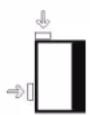
1-Sided Print Jobs
Load the drilled paper into any tray in the Long Edge Feed (LEF) direction. Refer to the following illustration:
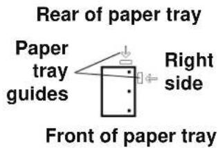
text_image
Rear of paper tray Paper tray guides Right side Front of paper tray2-Sided Print Jobs
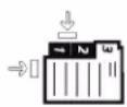
Load drilled paper into any tray in either the Long Edge Feed (LEF) or Short Edge Feed (SEF) direction. Refer to the following illustration:

text_image
LEF direction Rear of paper tray Paper tray guides Right side Front of paper tray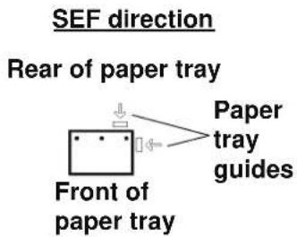
text_image
SEF direction Rear of paper tray Front of paper tray Paper tray guides
NOTE: If you are stapling 3-hole drilled paper with the optional Common Stacker Stapler (CSS), refer to Chapter 4 Accessories for paper loading instructions based on the position of the staple.
Letterhead

Different inks and dry inks/toners are used to produce preprinted letterhead that may not pass through the digital press intact.
Refer to the Specialty Media Guide: Hints and Tips for information on using preprinted letterhead paper.
Custom (nonstandard) size paper
Custom (nonstandard) size paper is identified as any paper for which there is no paper guide setting within the minimum and maximum sizes for the trays: 7.2 to 12.6 inch LEF or 7.2 to 19.2 inch SEF (182 - 320 mm LEF or 182 x 488 mm SEF)
Custom size paper can be loaded into all the trays. The Custom setting must be selected on the top/front of the paper tray.
Refer to the Administrator Guide for the procedure to program custom size paper.
Paper weight conversion tables
Specific weight conversion
| Grammage (g/m2) | Xerographic Bond, Writing, pounds 17 x 22” - 500 sheets | Offset, Text, Book, pounds 25 x 38”- 500 sheets | Cover, pounds 20 x 26” -500 sheets | Index, pounds 25.5 x 30.5” - 500 sheets | Bristol and Tag, pounds 22.5 x 28.5” - 500 sheets |
| 60 16 41 22 33 27 | |||||
| 64 17 43 24 35 29 | |||||
| 75 20 50 28 41 34 | |||||
| 80 21 54 30 44 36 | |||||
| 90 24 60 33 50 41 | |||||
| 105 28 70 39 58 48 | |||||
| 120 32 80 44 66 55 | |||||
| 135 35 90 50 75 62 | |||||
| 150 40 100 55 83 67 | |||||
| 158 42 107 58 87 72 | |||||
| 163 43 110 60 90 74 | |||||
| 176 47 119 65 97 80 | |||||
| 200 53 135 74 110 91 | |||||
| 203 54 137 75 112 93 | |||||
| 216 57 146 80 119 98 | |||||
| 220 59 149 81 122 100 | |||||
| 259 66 169 92 140 114 | |||||
| 280 74 189 104 155 128 | |||||
| 300 74 189 104 155 128 |
Yellow shading indicates grades widely used for this classification
Weight conversion ranges
| Grammage (g/m2) | Xerographic Bond, Writing, pounds 17 x 22" - 500 sheets | Offset, Text, Book, pounds 25 x 38" - 500 sheets | Cover, pounds 20 x 26: - 500 sheets | Index, pounds 25.5 x 30.5" - 500 sheets | Bristol and Tag, pounds 22.5 x 28.5" - 500 sheets |
| 60 - 80 17 - 21 | 43 - 54 24 - 30 | 35 - 44 29 - 36 | |||
| 81 - 105 22 - 28 | 55 - 70 31 - 39 | 45 - 58 37 - 48 | |||
| 106 - 135 29 - 36 | 71 - 90 40 - 44 | 59 - 75 49 - 62 | |||
| 136 - 150 37 - 40 | 91 - 100 45 - 55 | 76 - 83 63 - 67 | |||
| 151 - 220 41 - 59 | 101 - 149 56 - 81 | 84 - 122 68 - 100 | |||
| 221 - 300 | 60 - 74 | 150 - 189 | 82 - 110 | 123 - 166 | 101 - 128 |
Loading paper
Use this procedure to load paper in any paper tray.
NOTE: Many suppliers use arrows on the paper ream labels to indicate the preferred side to image first. Use this side (as indicated by the arrow) as equivalent to the seam side when loading the paper.
NOTE: Opening the paper tray may cause the Tray Properties window to open automatically. This depends on whether or not the user has this option selected; refer to page 2-7 of this guide for more information.
-
Pull out the tray slowly until it stops.
-
Load the correct size paper into the tray in the correct feeding orientation.
-
Load the paper seam side (the side on which the ream of paper is sealed) up in all the trays.
- Do not load materials above the MAX line located on the rear Edge Guide.
-
Do not store extra reams of paper in the open area of the paper trays. The tray will become inoperable until the paper is removed.
-
Adjust the paper guides by pressing in the guide release and carefully moving the Edge Guide until it lightly touches the edge of the material in the tray.
- From the Tray Properties window, enter the correct paper information, including size, type, and weight, and if required, decurler profile and alignment profile selections.
- Select OK to save the information and close the Tray Properties window.
- Close the paper tray.
- All the trays have auto size detection capability. The loaded paper size, weight, type, and orientation is displayed on the UI screen once the tray is closed.
- Selecting the correct paper weight range affects the throughput performance and image quality.
• Refer to the table on page 3-9 to convert pounds to grams.
Paper trays air adjustment:
Blowers help control the environmental conditions in the paper trays to ensure optimum print capability:
• Each paper tray has two blowers and two fans. The blowers are located in the front of each tray, while the two fans are located on the right-side of the tray.
- The lead edge blower is on at all times and produces heated air if one of the following selections are made: Coated paper, Transparencies, or plain paper 106g / m^2 or heavier. The trail edge blower is on at all times and does not produce heated air.
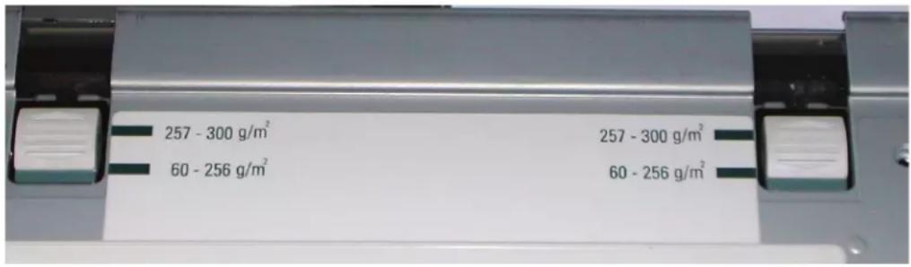
- The paper trays also have air adjustment levers on the drawer to regulate the direction of the air.
If the paper weight is between 60 and 256 g/m ^2 , the position of the air adjustment levers should be toward the front of the tray.
If the paper weight is between 257 and 300 g/m ^2 , the position of the air adjustment levers should be positioned toward the rear of the tray.
text_image
257 - 300 g/m² 60 - 256 g/m² 257 - 300 g/m² 60 - 256 g/m²Tray Stock Mismatch
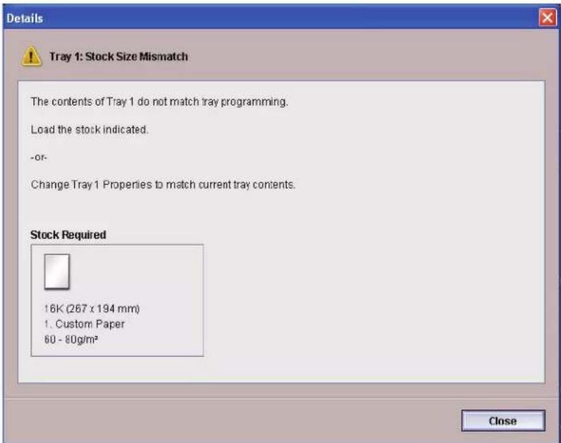
text_image
Details Tray 1: Stock Size Mismatch The contents of Tray 1 do not match tray programming. Load the stock indicated. -or- Change Tray 1 Properties to match current tray contents. Stock Required 16K (267 x 194 mm) 1. Custom Paper 60 - 80g/m² CloseIf the paper loaded in a tray does not match the information on the Tray Properties window, the UI alerts you with a Tray Stock Size Mismatch message. Also, if you receive a Tray Stock Size Mismatch message, check the paper tray guides to ensure that they are positioned correctly.
If you receive this message, do the following:
-
Load the stock indicated on the Tray Stock Size Mismatch window, or
-
Change the Tray Properties to match the contents of the tray.
a. Verify the paper size, type (coated, uncoated, etc.), and weight of the paper loaded in the tray.
b. Enter that information on the Tray Properties window.
3. Paper information
4. Accessories
Trays 3 and 4 (Second Feeder Module)
The Second Feeder Module is an optional feeding device that contains Trays 3 and 4. This module holds the same number and types of substrates as the First Feeder Module (FFM), which contains Trays 1 and 2. The First Feeder Module is not optional and is permanently connected to the digital press.
Each tray holds a maximum of 2000 sheets of 24 pound (90 g/m²) paper. Refer to “Paper guidelines” in Chapter 3 on page 3-5 for more information on using specific types of paper.
NOTE: Always refer to the Recommended Materials List and the Speciality Media Guide.
Identifying the parts
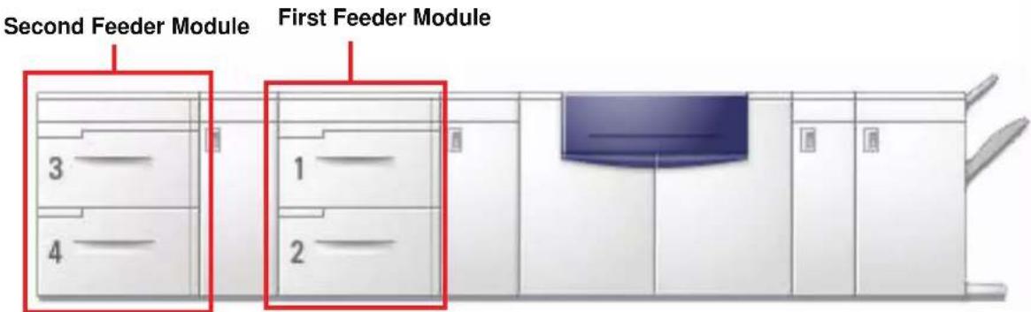
text_image
Second Feeder Module First Feeder Module 3 4 1 2Paper path
Paper feeds from the right side of the trays. Sheets move from the transport area behind the right door of the SFM to the Upper Transport area above Paper Trays 1 and 2, then through the Transport Module and into the press.
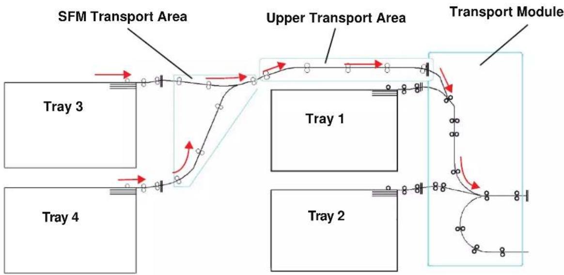
flowchart
graph TD
    A["Tray 1"] --> B["Upper Transport Area"]
    C["Tray 2"] --> D["Upper Transport Area"]
    E["Tray 3"] --> F["TFM Transport Area"]
    G["Tray 4"] --> H["TFM Transport Area"]
    I["Transport Module"] --> J["TFM Transport Area"]
    style A fill:#f9f,stroke:#333
    style C fill:#f9f,stroke:#333
    style E fill:#f9f,stroke:#333
    style G fill:#f9f,stroke:#333
    style I fill:#f9f,stroke:#333
    style J fill:#ccf,stroke:#333
Paper guidelines
For the best results, remember the following:
- Do not load paper or other materials above the MAX line on the rear paper guide.
- Do not store extra reams of paper in the paper trays.
- Do not use wrinkled, torn, curled, or folded paper.
- Use the paper sizes and weights shown in the Recommended Materials List.
- Follow the suggestions in the Specialty Media Guide: Hints and Tips.
- Do not mix sizes or weights of paper in a paper tray.
- Ensure that the tray is set for the correct paper size, weight range, and paper type.

NOTE: It is imperative that you load paper with the paper guides adjusted properly. If the paper is NOT loaded properly, it will skew and jams will occur.
Paper Specifications
| Paper All Paper Trays | ||
| Minimum Paper Size 182mm x 182mm | (7.2 x 7.2") | |
| Maximum Paper Size 320mm x 488mm | (12.6 x 19.2") | |
| Standard Sizes B5 LEF/SEF | B4 SEF8 x 10" LEF/SEF8.5 x 13" SEF11 x 17" SEF12.6 x 17.7" SEF^(1) SRA3" (320 mm x 450mm) SEF | A4 LEF/SEFA3 SEF8.5 x 11" LEF/SEF8.5 x 14" SEF12 x 18" SEF12.6 x 19.2" SEF^(1) |
| Paper Weight Range | 60 - 300 g/m ^2 (16 lb bond - 110 lb cover) | |
| Transparencies ^(2) | Yes(A4 LEF or 8.5 x 11" LEF) | |
| Labels ^(2) | Yes | |
| Transfer Paper ^(2) | No | |
| Coated Paper (120 g/m ^2 /80 lb) ^(3) (4) | Yes | |
| Uncoated Paper (90 g/m ^2 /24 lb) | ||
| Tabbed Inserts ^(5) | Yes | |
| Drilled (LEF) Yes: 2, 3, 4 hole | ||
| Carbonless paper Yes | ||
(1)Refer to the "Custom (nonstandard) size paper" on page 3-8.
(2)Refer to the Recommended Materials List and the Speciality Media Guide for guidelines.
(3)Duplex is limited to paper that is 220 g/m² or less.
(4) L80 g/m ^2 cannot duplex in high humidity. L85 g/m ^2 coated media is not allowed.
(5)Refer to the "Tabbed inserts" on page 3-6.
Loading paper
Loading paper in Trays 3 and 4 is the same as it is for Trays 1 and 2; therefore, use the same procedure for loading paper. Refer to page 3-11 for the procedure.
Paper trays air adjustment
Blowers help control the environmental conditions in the paper trays to ensure optimum print capability. For additional information, see “Paper trays air adjustment:” in Chapter 3 on page 3-12.
Jam clearance
A paper jam anywhere in the digital press is indicated by a message on the UI. Follow the instructions displayed to clear the jam in the area or areas displayed on the screen and to resume printing. Additional jam clearance instructions are also provided in Chapter 5 on page 5-5.
Physical characteristics
Size
41.7 inches/1060 mm W x 29.5 inches/750 mm D x 38 inches/969 mm H.
Weight
551 pounds/250 Kg.
Floor space requirements
Ask your Xerox representative to refer to the Installation Planning Guide for installation work space requirements.
The High Capacity Stacker (HCS) is an optional finishing device that provides stacking and offsetting capabilities for output to the HCS Stacker Tray. The HCS connects to the right side of the digital press and replaces the Offset Catch Tray.
natural_image
Exterior view of a white industrial machine with a closed lid and internal ventilation duct (no visible text or symbols)The HCS Stacker Tray has a capacity of 3500 sheets of 24 lb (90 g/m ^2 ) centerline paper (or 370 mm high). The HCS Top Tray has a capacity of 250 sheets of 24 lb 90 gm ^2 centerline paper. The HCS is supplied with two Stacker Carts. If needed, you can purchase an additional Stacker Cart. Contact your Xerox representative for further details.

NOTE: The Stacker Tray cannot support more than 99 lb. (45 kg) of printed material and therefore, cannot hold 3500 sheets of coated paper (for example SRA3).
With the HCS you can:
- Select Offset Mode when collated sets are sent to the Stacker Tray.
- Send documents to the top tray.
- Send sets of different sizes to either the Stacker Tray or the top tray.

NOTE: To avoid jams, do not stack larger sets on top of smaller sets, or stack paper on top of transparencies.
- Send a sample set to the top tray.
- Chain two High Capacity Stackers to the digital press and send collated sets to HCS 1, HCS 2 or both High Capacity Stackers.
- Send collated sets through the stacker to another connected finishing device.
Identifying the parts
Control panel
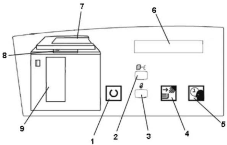
text_image
Diagram of a printer front panel with numbered components and control buttons| Item Number | Name Function | |
| 1 | Ready light | The Ready light blinks during initialization and is constant when the HCS is in use or in standby mode. |
| 2 Sample set button | Press to have the HCS deliver the next collated set to the top tray. | |
| 3 Unload | button | Press once to lower the Stacker Tray and unlock the front door. If pressed while running a job, all sheets in the paper path are delivered before the Stacker Tray starts to lower. |
| 4 | Unload light | Illuminates when the Stacker Tray has reached the down position and the front door can be opened. |
| 5 | Wait light | Blinks when the Stacker Tray is moving up or down. |
| 6 Fault code display | Displays a code when a fault occurs in the stacker. Refer to the HCS fault code table located in the Problem Solving section of this chapter. | |
| 7 Top tray jam area | Blinks when there is a jam.Illuminates when output is sent to the tray. | |
| 8 Bypass jam area | Blinks when there is a jam. | |
| 9 Stacker tray jam area | Blinks when there is a jam or the door is open.Illuminates when output is sent to the tray. | |
| Not applicable | Keypad (not shown) | Used by the service representative for diagnostics. The keypad is located on the front right of the control panel. |
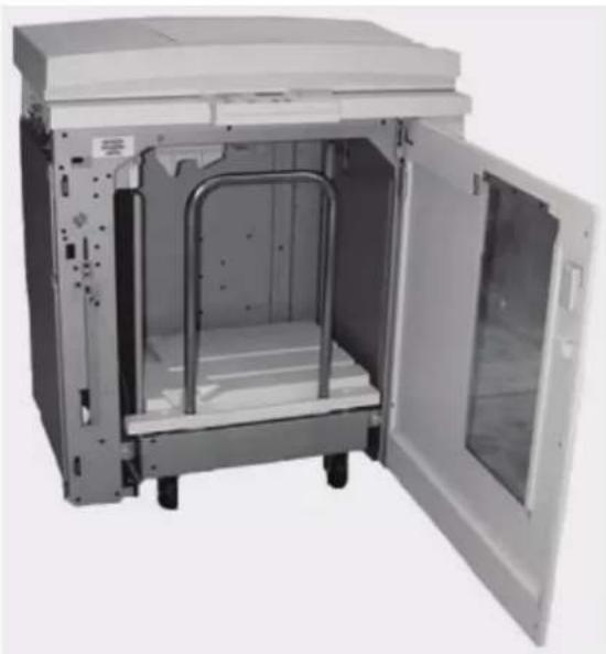
Cooling fan
The stacker is equipped with a cooling fan that you can switch on and off as required. The cooling fan is located inside the front door:

text_image
Cooling FanThe cooling fan is normally Off. The fan must be switched On when you are using coated paper than weighs 120 g/m^2 (80 lb.) or greater.
For coated paper than weighs less than 120 g/m^2 (80 lb.) and for uncoated paper, the fan should be switched Off.

To switch On the cooling fan, perform the following steps:
-
Push the Unload button to lower the tray.
-
Open the front door.
natural_image
Interior view of a laboratory or industrial chamber with metal components and a closed door (no visible text or symbols)- Press the cooling fan power switch to the On position.
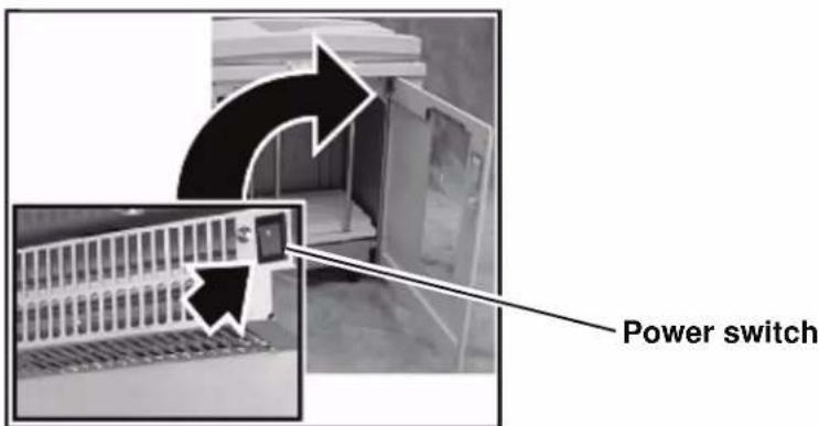
text_image
Power switchTIP: Only switch on the cooling fan when running paper that weighs 120 g/m^2 (80 lb.) or greater.
NOTE: Remember to switch off the fan after your job(s) finishes and when running paper that weigh less than 120 g/m^2 (80 lb.).


Paper path

TIP: Labels must be sent to the HCS Top Tray.
Top Tray
Sheets are transported to the HCS Top Tray:
- When sheets are purged after a paper jam.
- When the Sample Set button is selected.
- When selected as an Output Location.

text_image
Top Tray Bypass From the Digital Press Stacker Tray Stacker CartStacker Tray
Collated sets are transported to the HCS Stacker Tray.
Bypass
The Bypass transports collated sets through the HCS to a connected finishing device or to another HCS.
If your system configuration has two High Capacity Stackers, the bypass on the second HCS is not available.
Paper guidelines
- The HCS Stacker Tray accepts 60-300 g/m ^2 (either coated or uncoated stock) with the possibility of degraded stock quality and increased jam rate
- Transparencies may be run to either the HCS Top Tray or the HCS Stacker Tray. Stack height should be limited to 100 transparencies.
- Coated paper lighter than 100g / m^2 may not run as reliably as coated paper heavier than 100g / m^2 .
Recommended baseline/centerline
The following papers are considered to be baseline/centerline and are recommended to ensure you receive the best quality from your stacker:
- Uncoated: Xerox Digital Color Xpressions+, 90 g/m ^2 , 24 lbs. In Europe, Xerox Digital Color Colotech+ 90 g/m ^2 .
- Coated: Xerox Digital Color Gloss Coated Text (120 g/m ^2 /80 lbs.) In Europe, Xerox Digital Color Colotech + Gloss Coated 120 g/m ^2 .
Paper specifications
| Paper Size Output | |||||
| Industry Designation | Inches Orientation Stacker Tray | 60 - 300g/m2 | Bypass 60 - 300 g/m2 | Top Tray 60 - 300 g/m2 | |
| B5 7.2 x 10 | 1 SEF Yes Yes | Yes | |||
| B5 7.2 x 10 | 1 LEF Yes Yes | Yes | |||
| A4 8.3 x 11 | 7 SEF Yes Yes | Yes | |||
| Letter 8.5 x 11 | 1 SEF Yes Yes | Yes | |||
| 8.5 x 13 | SEF Yes Yes Yes | ||||
| Legal | 8.5 x 14 | SEF | Yes | Yes | Yes |
| B4 | 10.1 x 14.3 | SEF | Yes | Yes | Yes |
| 11 x 14.9 | SEF Yes Yes Yes | ||||
| Tabloid | 11 x 17 | SEF | Yes | Yes | Yes |
| A3 | 11.7 x 16.5 | SEF | Yes | Yes | Yes |
| 12 x 18 | SEF Yes Yes Yes | ||||
| SRA3 | 12.6 x 17.7 | SEF | Yes | Yes | Yes |
| 8 x 10 | LEF | Yes | Yes | Yes | |
| A4 | 8.3 x 11.7 | LEF | Yes | Yes | Yes |
| Letter | 8.5 x 11 | LEF | Yes | Yes | Yes |
| Kai8 | 10.5 x 15.3 | SEF | Yes | Yes | Yes |
| Kai16 | 10.5 x 7.6 | LEF | Yes | Yes | Yes |
| Transparencies | A4 & Letter | LEF | Yes* | Yes* | Yes* |
| Labels | A4 & Letter | LEF | No | Yes* | Yes* |
*Customer recommendation is to run stacks of less than 100, but there is no system limit on customer selection.
Unloading the Stacker Tray
Use the following procedure to unload the HCS Stacker Tray when it is full, or you want to retrieve a job that has been completed.
- Press the Unload button on the HCS Control Panel. The Wait light blinks until the HCS Stacker Tray has reached the down position.
- Open the front door when the Unload Light illuminates.
- Position the securing bar on top of the stacked paper.
- Pull the HCS Stacker Cart straight out.
- Remove the securing bar.
- Remove the paper from the HCS Stacker Tray.
- Push the empty Stacker Cart straight into the HCS.
- Position the securing bar on the fixed area inside the HCS.
NOTE: The front door will not close if the securing bar is not properly attached to the HCS frame.
-
Close the HCS front door.
-
Follow the instructions displayed on the digital press UI to resume printing.

Selecting Features
For jobs coming through the network, refer to the documentation that came with your color server for information on how to select HCS options on the print driver screens.
How to Enable Automatic Output Switching
If your system configuration contains two High Capacity Stackers, you have the option to enable Automatic Output Switching. With Automatic Output Switching, the digital press automatically selects a usable HCS Stacker Tray to deliver your collated sets.
When the HCS Stacker Tray becomes full or when the Unload button is selected, the digital press delivers all paper in the digital press to the same Stacker Tray and then switches to the other Stacker Tray for the rest of the job.

NOTE: The HCS Stacker Tray has a capacity of 3500 sheets of 24 lb (90 g/m ^2 ) centerline paper (or 370mm high). Always refer to the Recommended Materials List and the Speciality Media Guide for up-to-date information on using specific media types with the HCS.
Using a DFA Finishing Device
A DFA (Digital Finishing Architecture) finishing device can be connected directly to the digital press or to the HCS.
All DFA devices are installed by your Xerox service representative. Once installed, the UI screens provide Finishing Module selections.
For jobs coming through the network, refer to the documentation that came with your color server for information on how to select DFA options on the print driver screens.
Jam clearance
A paper jam in the HCS will be indicated by a message on the digital press UI. Follow the instructions displayed. The image on the stacker Control Panel will flash showing the area where the jam is located.
Clear Bypass area jam
natural_image
Interior view of a beige industrial machine with open lid and internal panel (no visible text or symbols)
Perform the following steps to clear the HCS jam in the Bypass area and resume printing.
- Remove any paper from the HCS Top Tray.
- Lift the HCS Top Cover.
- Lift the green handle, or handles, and remove all paper in the Bypass area. Remove paper only from the areas indicated.
- Close each green handle.
- Close the HCS Top Cover.
- If the UI indicates there is a jam in the digital press, follow the instructions on the screen to remove any paper in the area indicates. Additional jam clearance instructions are also provided in Chapter 5 on page 5-5.
- Follow the instructions displayed on the UI to resume printing.
Clear Top Tray and Stacker Tray paper jams

To clear the HCS Top Tray, remove all paper from the Top Tray. Perform the following steps to clear a jam from the HCS Stacker Tray area and resume printing.
- Press the Unload button on the HCS Control Panel. The Wait light blinks until the Stacker Tray has reached the down position.
- Open the front door when the Unload Light illuminates.
- Position the securing bar on top of the stacked paper.
- Pull the HCS Stacker Cart straight out.
- Reach into the HCS and remove any jammed paper.
- Push the Stacker Cart straight into the HCS.
- Position the securing bar on the fixed area inside the HCS.
NOTE: The front door will not close if the securing bar is not properly attached to the HCS frame.

-
Close the HCS front door.
-
Follow the instructions displayed on the digital press UI to resume printing.
Maintenance
Do not clean any area inside the HCS unless otherwise instructed by Xerox. If the covers or Front Door require cleaning, dampen a paper towel or soft, clean cloth with a liquid, nonabrasive glass cleaner or water.
To avoid damage to the HCS, do not pour or spray the cleaner or water directly onto the HCS. Always apply the liquid to the cloth first.
Do not use any other cleaners or solvents on the HCS as they may interact with the paint on the covers, eventually causing the paint to peel.
Problem Solving
If, after following the recommended solutions, the problem persists, call for assistance. The Fault Codes described below appear on the HCS display panel.
| Fault Code Cause | Solution | |
| 212 100212 110212 120212 130212 140212 900 | Paper jam A jam occurred during feeding. Remove sheets from jam clearance areas. Open and close the top cover and front door. A purge sheet may eject to the top tray.If the jam occurs in the second HCS, be sure to check the Bypass area in the first HCS. | |
| 212 251212 252212 253212 254 | Stacker problem Power off, then power on. | |
| 212 302 Top Cover open Close the top cover. | ||
| 212 540 Stacker tray full Empty the Stacker Tray. | ||
| 212 541 | Stacker tray position | Press the Unload button. The Wait light blinks until the Stacker Tray has reached the down position.When the Stacker Tray has reached the down position, open the front door.Remove the Stacker Cart.Remove all stacked paper.Position the Stacker Cart securely into the HCS.Close the front door. |
| 212 542 No Stacker Cart Open the front door. | Remove the Stacker Cart from the HCS.Position the Stacker Cart securely into the HCS.Close the front door | |
| 212 544 Door open Close the door | ||
Loss of Power
If power is interrupted to the HCS:
- Ensure the power cord is plugged in to the proper wall receptacle.
- Ensure that the digital press power is on and the Ground Fault Indicator is in the On position.
- If the power has not been restored by the above procedure, call Xerox Customer Support.
Also call your Xerox service representative if the loss of power to the HCS seems to be frequent or excessive.
Common Stacker/Stapler (CSS)
The Common Stacker/Stapler (CSS) is an optional finishing device which provides stacking with offset and single or dual stapling output capabilities. Sets of up to fifty sheets of 64-80 g/m ^2 may be stapled.
The CSS must be connected to the right end of the digital press, replacing the Offset Catch Tray. The CSS Stack Tray has a capacity of 2000 sheets of 17-21 lb. (64-80 g/m²) paper. The stacker/stapler also has an Offset mode which provides separation between the stacked sets sent to the CSS Stack Tray. The stacker/stapler can also send output (not stapled) of 250 sheets of 17-21 lb. (64-80 g/m²) paper to the CSS Top Tray.
Banner sheets can be used with your color server. The banner sheets must be printed on LEF 8.5 x 11 in. paper. Refer to your color server manual for more information on how to turn this feature on.
Identifying CSS Parts

text_image
Top Tray Offset Stacker/ Stapler TrayControl Panel

text_image
4 3 1 2 5 6 7 8 9 10 11 12 13 14 15 16 17 18 19 20| Item Number | Name Function | |
| 1 Ready | Indicator | The Ready Indicator blinks when the digital press is being initialized. The Ready Indicator is constant when in use or in standby. |
| 2 Staple | Indicator | The Staple Indicator blinks when the staple level in the stapler is low. The Staple Indicator is constant when the stapler is empty. |
| 3 Keypad | The keypad, including the C button, is used only by the Xerox service representative. | |
| 4 Message | Display | Shows the fault codes. |
| 5 | Jam Indicator | Area illuminates to indicate the location of a jam in the CSS and the output location being used. |
Electrical/environmental requirements
Western Hemisphere: 115 VAC, 15 amp, for 60 Hz. and 220 VAC, 10 amp for 50 Hz installations.
Europe: 200-240 Volt 10 amp 50 Hz service outlet.
The stacker/stapler requires a separate power source from the digital press.
| Environmental requirements | Minimum Maximum |
| Temperature: 10^ C (50° F) 32^ C (90° F) | |
| Relative Humidity (% RH): | 20% 80% |
| Altitude: Not applicable | 2000 meters (6560 ft.) above sea level may require field adjustments |

NOTE: Best machine performance is achieved when conditions are maintained between 20-25° C (68-77° F).
Paper stock specifications
The CSS Top Tray accepts all media types, sizes, and weights supported by the digital press. The CSS Stack Tray accepts all standard media sizes supported by the digital press with the including sizes that are larger than A3/11 x 17 in.

TIP: Paper that is larger than A3/11 x 17 inch cannot be stapled or offset.
Refer to the following chart for information on accepted media types.
| Paper Size Output | ||||||
| CSS Stack Tray17-59 lb. (60-220 g/m2) | CSS Top Tray | |||||
| Name Inches MM Orientation | Can feed to the Stack Tray?Yes/No | Staple Position(50 sheet maximum for Stapling*) | 17-75 lb.(60-300 g/m2) | |||
| JIS B5 | 7.2x10.1 | 182 x 257 | SEF | Yes | Portrait | Yes |
| A4 | 8.3x11.7 | 210 x 297 | SEF/LEF | Yes | Portrait/ Landscape | Yes |
| Letter | 8.5x11 | 216 x 279 | SEF/LEF | Yes | Portrait/ Landscape | Yes |
| 8.5x13 | 216 x 330 | SEF | Yes | Portrait/ Landscape | Yes | |
| 8.5x14 | 216 x 256 | SEF | Yes | Portrait/ Landscape | Yes | |
| JIS B4 | 10.1x14.33 | 257 x 364 | SEF | Yes | Portrait | Yes |
| 11x17 | 279 x 432 | SEF | Yes | Portrait/Dual | Yes | |
| A3 | 11.7x16.5 | 297 x 420 | SEF | Yes | Portrait/Dual | Yes |
| 12x18 | 305 x 457 | SEF | Yes | Not available | Yes | |
| SRA3 | 12.6x17.7 | 320 x 450 | SEF | Yes | Not available | Yes |
| 12.6x19.2 | 320 x 488 | SEF | Yes | Not available | No | |
| B5 | 7.2x10.1 | 182 x 257 | LEF | Yes | Portrait | Yes |
| 8x10 | 203 x 254 | LEF | Yes | Portrait | Yes | |
* Refer to the table on page 4-24 for information on the stapling capacity for various paper types and weights.

NOTE: Transparencies can be fed to both CSS trays.

TIP: Paper that is larger than A3/11 x 17 inch cannot be stapled or offset.
Paper Path
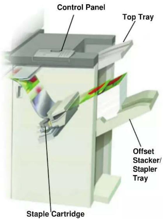
text_image
Control Panel Top Tray Offset Stacker/ Stapler Tray Staple CartridgeAs media enters the CSS, it is fed to the CSS Top Tray or to the CSS Offset Stacker/Stapler Tray, depending on your selections.
Using the stacker/stapler
Use the CSS by sending a document through the network and making your selections under Job Properties/Parameters. If you are sending a job through the network, refer to the manuals that came with your color server for information on how to set the job Properties/Parameters when using the CSS.
Hints and tips
- The CSS cannot staple jobs with mixed sizes of paper.
- The stacking may be skewed on the output from mixed size paper jobs.
- You can use mix-coated and uncoated stock.
- The CSS accepts jobs of mixed weight papers below 59 lb. (220 g/m ^2 ).
- Only clear paper jams at the area indicated on the CSS Control Panel. Do not remove paper from any other areas of the paper path.
Stapling Hints
There are three stapling options:
- Single Staple Position 1: The CSS places a staple in the upper left corner of SEF or LEF sets.
- Single Staple Position 2: The CSS places a staple in the bottom left corner of SEF sets only.
- Dual Staple: The CSS places two staples closer to the top/bottom center of the sheets than a single staple.
All three of these positions are illustrated in the Staple Positions table on page 4-25.
Paper specifications for stapling
The following chart shows the stapling details for paper size, orientation, destination, and staple position. Numbers have been rounded up or down.
| Staple Positions marked with an “O” may be selected in the position indicated. Positions marked with an “X” are not available for stapling. ^1 Front Corner = Single Staple Position 1 ^2 Rear Corner = Single Staple Position 2 | Output Destination | Staple Position (Output fed to Stack Tray) | Output Destination | ||||
| Inches MM | Sheet Orientation | Stack Tray 64-220 g/m^2 | Front corner ^1 | Rear corner ^2 | Dual | Top Tray 64-300 g/m^2 (no stapling) | |
| 7.2 x 10.1 | JIS B5 (182 x 257) | SEF Yes O X X Yes | |||||
| 8.3 x 11.7 | A4 (210 x 297) | SEF | Yes | O | O | X | Yes |
| 8.5 x 11 | 216 x 279 | SEF | Yes | O | O | X | Yes |
| 8.5 x 13 | 216 x 330 | SEF | Yes | O | O | X | Yes |
| 8.5 x 14 | 216 x 356 | SEF | Yes | O | O | X | Yes |
| 10.1 x 14.3 | JIS B4 (257 x 364) | SEF Yes O X X Yes | |||||
| 11 x 17 | 279 x 432 | SEF | Yes | O | X | O | Yes |
| 11.7 x 16.5 | A3 (297 x 420) | SEF | Yes | O | X | O | Yes |
| 12 x 18 | 305 x 457 | SEF | Yes | X | X | X | Yes |
| 12.6 x 17.7 | 320 x 450 | SEF | Yes | X | X | X | Yes |
| 12.6 x 19.2 | 320 x 488 | SEF | Yes | X | X | X | Yes |
| 7.2 x 10.1 | B5 (182 x 257) | LEF | Yes | O | X | X | Yes |
| 8 x 10 | 203 x 254 | LEF | Yes | O | X | X | Yes |
| 8.3 x 11.7 | A4 (210 x 297) | LEF | Yes | O | X | O | Yes |
| 8.5 x 11 | 216 x 279 | LEF | Yes | O | X | O | Yes |
| 10.5 x 15.3 | Kai 8 (267 x 388)Asian market size | SEF Yes O X X Yes | |||||
| 10.5 x 7.6 | Kai 16 (267 x 194) Asian market size | LEF | Yes | O | X | X | Yes |

TIP: Paper that is larger than A3/11 x 17 inch cannot be stapled or offset.

NOTE: Stapled sets of large paper (A3, 11 x 17in. and greater) may stack slightly skewed. The stapled sets will be of high quality.
Staple Positions
| Size: Inches (mm) | Staple Position 1(Front Corner) | Staple Position 2(Rear Corner) | Dual Staple | |||
| SEF LEF SEF LEF SEF | LEF | |||||
| 7.2x10.1JIS B5(182x257) |  |  |  |  | ||
| 8x10(203x254) |  |  |  |  | ||
| 8x5x11(216x279)A48.5x13(216x330)8.5x14(216x356) |  |  |  |  |  | |
| 10.1x14.3JS B4(257x364)10.5x15.3Kai 16(267x388:Asian market size) |  |  |  |  | ||
| 10.5x7.6Kai 16(267x194:Asian market size) |  |  |  |  | ||
4. Accessories
| Size: Inches (mm) | Staple Position 1(Front Corner) | Staple Position 2(Rear Corner) | Dual Staple | |||
| SEF LEF SEF LEF SEF | LEF | |||||
| 11x17(279x432)A3 |  |  |  |  |  | |
| 12x18(305x457)12.6x17.7(320x450) |  |  |  |  |  |  |
Stapling capacity for different paper types and weights
Following is the staple capacity for various types and weights of paper.
| Paper Weight | Coated | Uncoated | Mix Sizes |
| 64–80 g/m2 | 50 50 No | ||
| 81–105g/m2 | 42 42 No | ||
| 106–135 g/m2 | 31 31 No | ||
| 136–186 g/m2 | 26 26 No | ||
| 187–220 g/m2 | 18 18 No | ||
| 221–300 g/m2 | No * No * No | ||
| Transparencies No No | No |
* 221 to 300g / m^2 paper, either coated or uncoated, cannot be stapled. These weights will be stacked in the Top Tray.

TIP: The Offset Stacker/Stapler Tray may be limited to a maximum of 50 staple sets. In order to avoid system shutdown or jams, ensure that small staple set jobs do not exceed 50 sets. Before you send a stapled-print job to the machine, enable the offset jobs feature; this will improve tray capacity.
Unloading the stacker/stapler
To ensure consistent quality, unload sets of less than four sheets and lighter weight paper after 50 sets are made, or when the curl of the sets inhibits the ability of the sets to exit the stacker/stapler.
When the Stack Tray is full, Fault Code 112-550 appears in the message display on the stacker/stapler. The digital press UI displays a message, "Unload the Main Tray of the Finisher."
The stacker/stapler continues to stack sheets into the Stack Tray after the message appears, but excess sheets may have a degraded stacking quality. For best performance, unload the tray when 2,000 sheets have been stacked.
Jam Clearance
A paper jam in the stacker/stapler is indicated by a message on the digital press UI. The stacker/stapler Control Panel display illuminates the area where the jam has occurred.
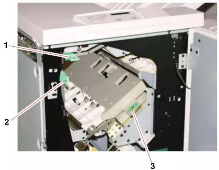
text_image
Technical diagram of an electronic device with numbered components labeled 1, 2, and 3
Read the following steps for more information on how to clear a jam.
- Open the stacker/stapler Front Door. There are three possible jam areas as indicated in the photo above. Handle 1 moves down, Handle 2 moves to the right, and handle 3 moves up.
- Remove all jammed paper only from the area indicated on the UI and the stacker/stapler Control Panel Display. Do not remove paper from any other areas.
- Reposition the handle.
- Close the stacker/stapler Front Door.
- Follow any instructions on the UI to restart your print job.
Ordering and Loading Staples
You can order new staple cartridges through the system you normally use for ordering Xerox supplies. The cartridge number to order is 8R12799. You should keep a supply on hand so production is not interrupted while you are waiting for staples to be shipped.
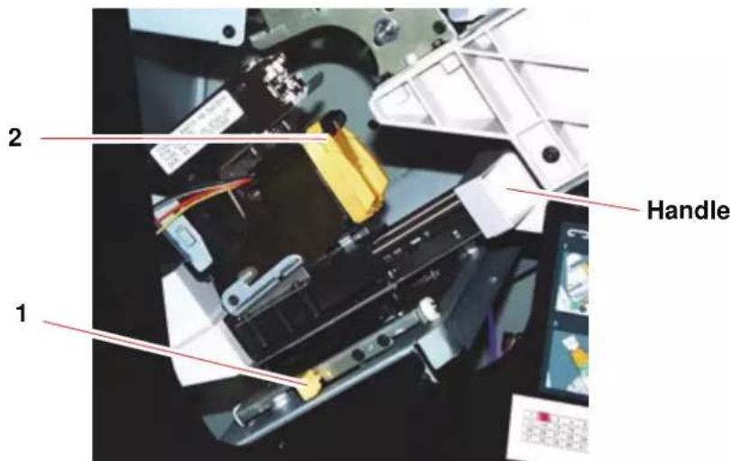
text_image
1 2 Handle
- Open the front door of the stacker/stapler.
- Push the Lever 1 down with your left hand. Grasp the handle on the cartridge unit and pull it towards you until it stops. Release the lever and the unit will lock into place.
- Grasp the staple cartridge (2) and pull it towards you. The entire unit will move forward, then the staple cartridge only will pull free of the unit.
- Insert a new cartridge into the unit, and push it until you hear it click into place.
- Push the yellow lever down and the cartridge unit automatically swings back into place.
Stacker/stapler Maintenance
Cleaning the stacker/stapler
Do not clean any area inside of the stacker/stapler unless otherwise directed by Xerox. If the stacker/stapler covers require cleaning, dampen a paper towel or soft, clean cloth with a liquid, nonabrasive glass cleaner or water.
To avoid damage to the stacker/stapler, do not pour or spray the cleaner or water directly onto the stacker/stapler. Always apply the liquid to the cloth first.
Do not use any other cleaners or solvents on the stacker/stapler or they may interact with the paint on the covers, eventually causing the paint to peel.
Problem Solving
If after reviewing the Problems and following the recommended solutions the problem persists, call for assistance.
| Problem Cause | Solution | |
| Fault Code 112-100 Jam indicated in stacker/stapler, but actually is in the Exit Module. | Jammed Paper not visible in stacker/stapler, and fault code does not clear after opening and closing stacker/stapler door. | ·Open the stacker/stapler door.·Jammed paper is not visible in the area indicated. Close the stacker/stapler door.·The UI indicates a jam in the Exit Module. Open the Exit Module and clear any visible sheets.·Open and close the stacker/stapler door.·Clear any other areas indicated on the UI. |
| Fault Code 112-100 Jam indicated in stacker/stapler. No visible jams in stacker/stapler because sheet is located over the Exit Module sensor. | Paper jammed between Exit Module and stacker/stapler sensors | ·Open the stacker/stapler door.·Jammed paper is not visible in the area indicated. Close the stacker/stapler door.·If the fault code remains, open the Exit Module. No jammed sheets are visible.·Undock the stacker/stapler. Find the jammed sheet between the Exit Module and the stacker/stapler. Refer to the Note below this table for information on how to undock the stacker/stapler.·Clear any other areas indicated on the UI. |
| Fault Code 112-130 Jam indicated in stacker/stapler, but is also in Exit Module. | Paper is jammed over both the Exit Module and stacker/stapler sensors. | ·Open the stacker/stapler door.·Clear any visible jams.·If no jammed paper is visible in the stacker/stapler area indicated, open the Exit Module door and clear any jammed paper. Close the Exit Module door.·Open and close the stacker/stapler door. |
| Fault Code 112-130 Jam indicated in stacker/stapler. | Paper is jammed between the Exit Module and the stacker/stapler sensors. | ·Open the stacker/stapler door.·If no jammed paper is visible in the area indicated, open the Exit Module door and clear any jammed paper. Close the Exit Module door.·Open and close the stacker/stapler door.·If the fault persists, undock the stacker/stapler and clear the jammed paper between the Exit Module and the stacker/stapler. Refer to the Note below this table for information on how to undock the stacker/stapler. |
| Fault Code 112-110 Paper | per jammed in the stacker/stapler and the Exit Module during a purge of sheets to the Top Tray. | ·Clear the jammed paper from the stacker/stapler.·Clear the jammed paper from the Exit Module.·Open and close the stacker/stapler door.·Resume job. |
| Fault Code 052-310 | Communication problem | ·Cancel or save the job.·Power off the digital press. Wait 15 seconds and power on. |
| Fault Code 052-321 | Connection problem | ·Cancel or save the job.·Power off the digital press. Wait 15 seconds and power on. |
| Fault Code 052-320 | Unexpected connection | ·Cancel or save the job.·Power off the digital press. Wait 15 seconds and power on. |
| Fault Code 052-312 | Communication problem | ·Cancel or save the job.·Power off the digital press. Wait 15 seconds and power on. |
| Ready Indicator does not illuminate | No power · Check the power cord connected to the power source.·Check that the main switch is on. | |
| Poor Stacking: Mixed sizes of paper Run separate jobs and empty stacker. | ||
| Paper Jams: | Use Top Tray | Deselect offset or restart job to the Top Tray. |
| High paper curl | Adjust digital press Decurler. See, “Decurler Profile” on page 2-5 for additional information.Flip paper in digital press paper tray(s).Rotate paper in the digital press paper tray(s).Switch to heavier paper. | |

NOTE: To undock the stacker/stapler from the digital press, reach into the circular area near the bottom of the stacker/stapler for the Undocking Lever. Refer to the picture below.
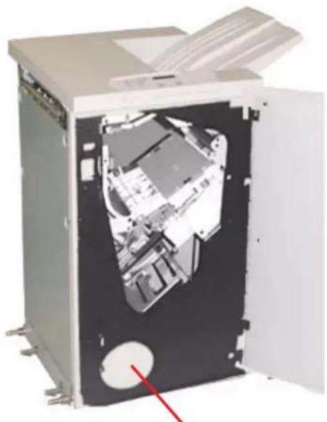
natural_image
Interior view of a mechanical washing machine with open door and internal components (no visible text or symbols)Location of Undocking Lever
Pull the lever toward you and hold it in position while moving the stacker/stapler a small distance (25.4mm, 1in.) away from the press. Release the lever and continue to move the stacker/stapler as far as required.
Loss of Power
If power is interrupted to the stacker/stapler:
- Ensure the power cord is plugged in to the proper wall receptacle.
- Ensure that the digital press power is on.
- If the power has not been restored by the above procedure, call Xerox Customer Support.
Also call your Xerox service representative if the loss of power to the stacker/stapler seems to be frequent or excessive.
5. Problem solving
When a problem occurs with your digital press, instructions appear on the UI. Refer to the information in this chapter to help resolve the problem.
General problems
If the digital press has a loss of power and you cannot access the Machine Details screen to get the serial number, open the two main front doors. The serial number label is in the center of the bottom frame of the digital press.
The charts on the following pages list problems and suggested solutions that apply to your digital press. If the problem persists after following all instructions, call your Xerox representative.

NOTE: If your color server indicates that the digital press has a fault and the UI does not readily display a message, select Machine Details from the System pull-down menu, then select the Error Log tab to display the fault history.
| Problem Suggested | solutions |
| The digital press does not power on. | ·Ensure the power cord is plugged into the receptacle correctly.·Ensure the power switch inside the front door is set to the ON position.·Check the GFI circuit breakers.·If the power in your location is working properly, you have tried the suggested solutions, and the digital press does not power on, call for assistance. |
| Prints are not on desired paper size. | ·Ensure that the proper paper is loaded in the paper trays.·Select the paper size, tray and weight through the digital press options on your PC.·Ensure that the correct weight is set on the Tray Properties window.·Ensure that “Fit to Paper” or an equivalent selection is not selected in your print driver. |
| Paper is misfed or wrinkles repeatedly. | ·If a message appears on the UI, follow the instructions displayed.·Ensure the proper paper is loaded correctly and not filled above the MAX line. Refer to The Recommended Materials List.·Turn the paper stack around and/or over in the selected paper tray.·Remove a few sheets from the top and the bottom of the stack in the paper tray.·Fan all four edges of the paper in the selected paper tray.·Replace the paper in the selected paper tray with paper from a new package.·Remove any partially fed paper from the trays.·Ensure the paper you are using had been stored properly. |
| Problem Suggested | Solution |
| The UI does not respond to a command. | Select Restart User Interface from the System pull-down menu on the UI.Select Shutdown System PC from the System pull-down menu. After the System PC shuts down, wait 15 seconds and restart it by pressing the on/off button on the PC.If the problem persists, call for service. |
| Transparencies are too oily. | Make 5 blank sheet copies with the Full Color option on paper stock to purge excess oil from system. Reload the transparencies and continue the copying job.Refer to the Recommended Materials List and the Color Materials Usage Guide for more information about transparencies. |
| Multiple sheets feed from the paper trays. | Do not fill the paper trays above the MAX fill line indicator.Remove the paper from the tray and fan the sheets to separate the joined sheets.Predrilled sheets may stick together at the holes. Remove the paper from the tray and fan the sheets to separate the joined sheets.Paper and transparencies may stick together if environmental conditions are too dry and cause excessive static. Increase the humidity level in the room to minimize static.Gently fan transparencies to separate the sheets before you load them. |
| Paper jams when exiting the Paper Trays | ·Ensure that the edge guides of the paper tray fit snugly against the paper stack.·Do not fill the paper trays above the MAX fill line indicator.·Close the tray slowly to avoid shifting the paper stack. |
| Output jams when exiting the digital press to the Offset Catch Tray | ·When no other output device is present, the Offset Catch Tray can hold up to 500 sheets of 24 pound (90 g/m2) paper. Empty the catch tray when output approaches this limit to ensure continuous production.·Ensure the first sheet is not blocking the paper exit, particularly for 11 x 17 inch (A3) output. |
| Excessive paper curl Paper curl | may be a result of:·Ensure that the correct paper weight and paper type are selected.·The mass of dry ink (toner) coverage on the print output - the greater the toner mass, the greater the paper curl.·The paper weight.·The humidity conditions at the digital press.·You can sometimes minimize curl problems by flipping the paper over in the tray and making the copies again. If excessive curl is still present, use a heavier paper.·Empty the output device when output approaches this limit to ensure continuous production.Paper curl may be a result of an attempt to print on thicker paper or on paper stock that is less sensitive to moisture.Note:If you have a problem with curl, you may want to use the Decurler adjustment options. Decurler Profile settings Default and A-D are available to the user. See, Chapter 2 Tray Properties for additional details. For additional information on the Decurler and the step-by-step instructions on using it, Chapter 3 of the Administrator Guide, which is located on your Customer Documentation CD, or atwww.xerox.com. |
| It is difficult to perform secondary operations on the output prints, such as writing on them or using adhesives. | This problem is caused by the oil used in the fusing process. The problem can be reduced or eliminated by setting the prints aside for one or two hours before performing a secondary operation on them. Rubbing the print surface with a soft, clean cloth or eraser may also help. |
Jam clearance
If a jam occurs, the digital press stops printing and a message is displayed on the UI. Follow all instructions displayed completely and in sequence, and follow the instructions provided here for further assistance in clearing the jam.
If power is interrupted during the printing process, it is imperative that you clear all other jam areas before you open and clear areas behind the Right and Left Front Doors of the digital press. The following illustration shows the various parts of the digital press. Follow the jam clearance instructions on the UI.
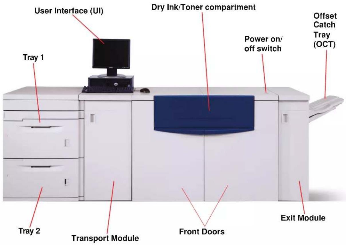
text_image
User Interface (UI) Dry Ink/Toner compartment Power on/ off switch Offset Catch Tray (OCT) Tray 1 Tray 2 Transport Module Front Doors Exit ModulePaper tray jams

CAUTION: Be careful of the Feed Heads and the Feed Rolls. They can be damaged with rough treatment.
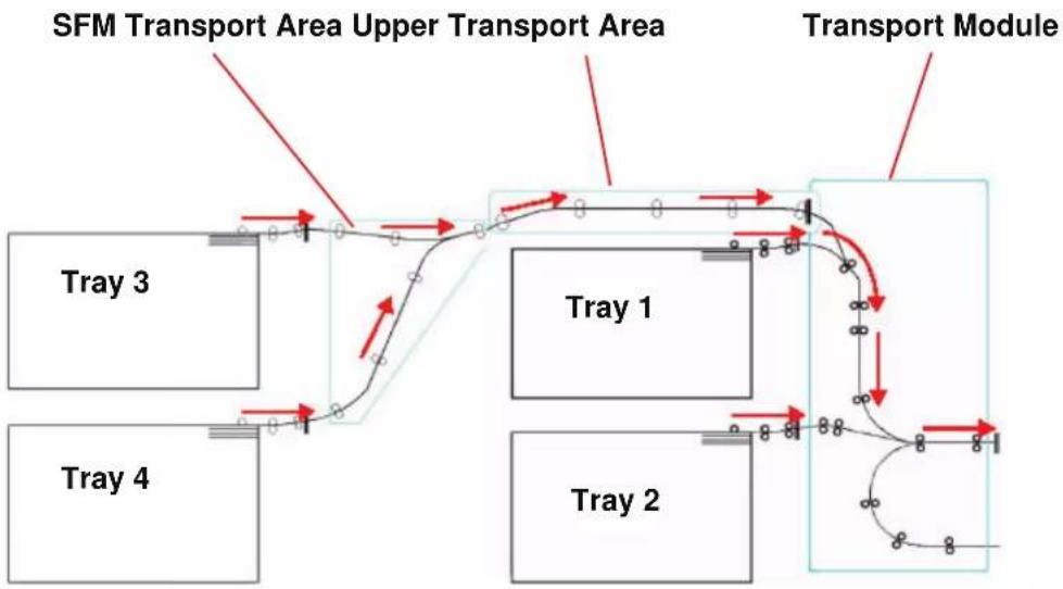
flowchart
graph TD
    A["Tray 1"] --> B["Transport Module"]
    C["Tray 2"] --> D["Transport Module"]
    E["Tray 3"] --> F["Transport Module"]
    G["Tray 4"] --> H["Transport Module"]
    I["SFM Transport Area Upper Transport Area"] --> J["Transport Module"]
    style A fill:#f9f,stroke:#333
    style C fill:#f9f,stroke:#333
    style E fill:#f9f,stroke:#333
    style G fill:#f9f,stroke:#333
    style I fill:#f9f,stroke:#333

The UI displays an animation showing the tray containing the jam.
- Open the tray with the jam.
CAUTION: If you hear paper tearing, stop opening the tray. Open the door of the Transport Module or the SFM Transport Area and clear the paper from the Transport Module before attempting to open the tray again.
-
Carefully remove all jammed paper.
-
Use the UI to determine if further jams exist and clear those areas.
Upper Transport Area jam

TIP: Jams occur in this area only when the Second Feeder Module containing Trays 3 and 4 is connected.
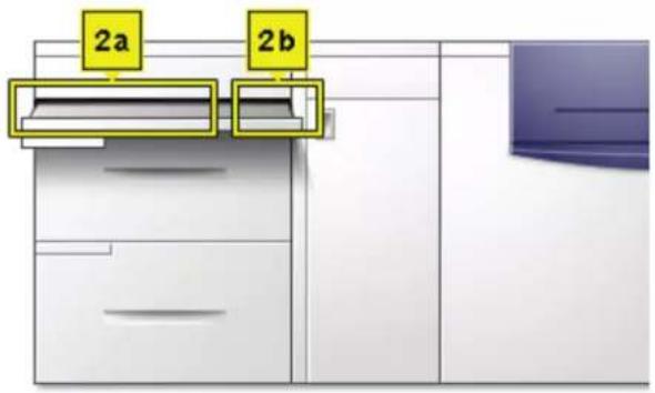
text_image
2a 2b
- Pull out the Transport Area Drawer above Tray 1.
- Lift up the handle.
- Remove all jammed paper.
- Return the drawer to its original position.
- Follow the instructions on the UI to clear other areas or to resume your print job.
Transport Module jams
Open the areas in the Transport Module indicated on the UI. Carefully remove all jammed paper.
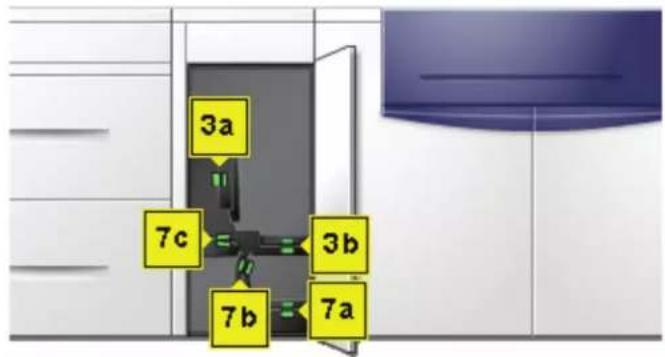
text_image
3a 7c 3b 7b 7a
- Open the Transport Module door.
- Grasp the green handles 3a, squeeze and move it to the right.
- Carefully remove all jammed paper.
- Reposition handles 3a.
- Lift up green handles 3b.
- Carefully remove all jammed paper and return handles 3b to their original position.
- Follow the UI messages and, if required, lift handles 7a and remove all jammed paper.
- Return handles 7a to their original position.
- Squeeze handles 7b and lower to the right. Remove all jammed paper.
- Return handles 7b to their original position.
- Squeeze handles 7c and lower to the left. Remove all jammed paper.
- Return handles 7c to their original position.
- Close the Transport Module door.
- Follow the instructions on the UI to restart your print job.
Exit Module jams
Follow the instructions on the UI to clear jams from all the areas indicated in the Exit Module. The following picture shows the areas where jams could be located.
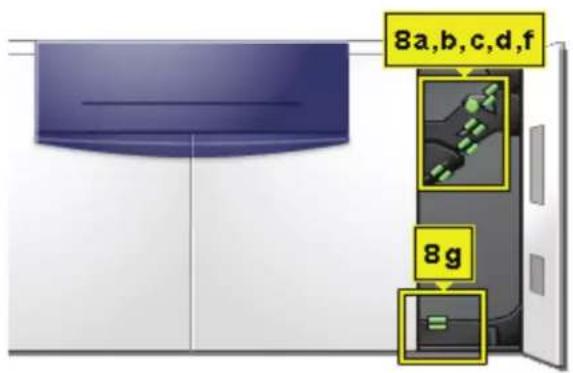
text_image
8a,b,c,d,f 8gFollow the instructions on the UI to restart your print job.
Right/left door paper path jams

Always follow the instructions on the UI to locate and clear jams.
TIP: It is imperative that you clear all other jam areas before you open and clear the Right and Left Front Door areas.

text_image
4a 4b 4 4e 4c 4d
CAUTION: Be careful when clearing jams in the Fuser area, The Fuser is extremely hot and will cause injury.
- Open the Right and Left Front Doors when directed to by a UI message.
- Grasp handle 4 and move it in the direction of the arrow.
- Slowly pull out the Paper Transport module until it stops.
- Lift handle 4a and carefully remove all jammed paper, ensuring that all pieces are removed if the paper is torn.
- Turn the green handle 4b to free any paper that is caught.
- Reposition green handle 4a.
CAUTION: Be careful when clearing jams in the Fuser area, The Fuser is extremely hot and will cause injury.
-
The Fuser area is on the right hand side of the Paper Transport module. Lift handle 4c on the right hand side and pull to open.
-
Lift up handle 4d until it stops and clear any jammed paper. Rotate knob 4e in the direction of the arrow on the knob to clear any paper that is caught.


NOTE: Occasionally a sheet of paper wraps around the heat roll. (The heat roll is visible when handle 4d is up). DO NOT attempt to remove this sheet of paper because the stripper fingers may be damaged if you attempt this procedure. Call your Xerox service representative to remove this piece of paper.
- Reposition green handle 4d and close area 4c. Ensure these are firmly in place.
- Grasp handle 4 and slowly push in the Paper Transport until it stops. Turn the handle in the direction of the arrow to lock the module in place.
- Close the Right and Left Front Doors.
- Follow the instructions on the UI to restart your print job.
Jam clearance with 2-sided printing
When printing 2-Sided output, the UI will direct you to clear the following areas if a jam occurs.
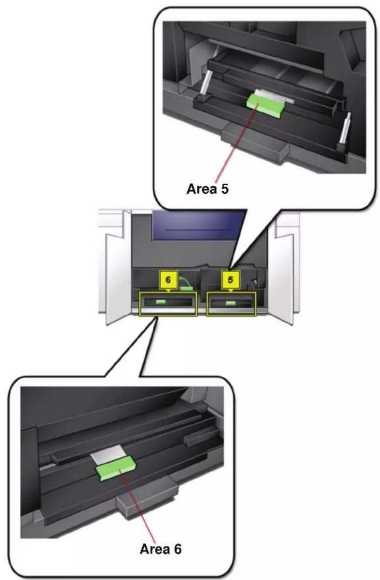
text_image
Area 5 6 5 Area 6

-
Open the Right and Left Front Doors when directed to by a UI message.
-
Lift handle 5 and clear any paper in the area.
CAUTION: Paper can rip if not pushed back before removing it from under the lip of this area.
-
Push the paper back until you see the front edge, then remove the paper.
-
Reposition handle 5 by closing firmly.
- Lift handle 6 and clear any paper in the area.
- Push the paper back until you see the front edge, then remove the paper.
- Reposition handle 6 by closing firmly.
- Close the Right and Left Front Doors.
- Follow the instructions on the UI to restart your print job.
Fault Codes

When there is a problem with the digital press or an accessory, refer to the UI where the Fault Code and a solution will be displayed. Follow all steps until the problem is corrected. If the problem persists, call one of the following numbers for assistance. Follow the instructions below before calling for service.
- Be prepared to provide a complete description of the problem to the service operator. Defining the problem accurately may help you and the operator solve the problem over the phone and minimize downtime. If the problem cannot be solved by telephone, a service representative will be dispatched to your site promptly.
- Record the displayed Fault Codes.
- Record the Machine Serial Number by selecting Machine Status from the System pull-down menu on the UI. (If the serial number is not displayed, open the Right/Left Front Doors of the digital press. The serial number is also on a white label on the bottom front frame.)
- If copy quality is a problem, take a copy sample to the telephone with you to help you describe the problem or to assist you when answering the questions from the service operator about the defects.
-
If possible, use a phone near the press when calling for assistance. Follow the instructions provided by the operator.
-
For system support, user help, and service support, call the appropriate number:
US:1-800-821-2797 (Includes TTY support)
Canada:1-800-939-3769
Europe:
Latin America:
Xerox also provides web-based customer support. Go to:
www.xerox.com/eSupportCentre
6. Technical Data
Digital Press Specifications
Electrical Power
Specifications
200-240V - 50/60 Hz
Single phase - Three wires plus safety ground
Current service - 30 Amp sole use @ 200V to 240V
Range (line to neutral) - 200 V minimum to 240 V maximum
Frequency - 50/60 Hz
Power Consumption
Standby - 3.0 kW
Run - 6 kW
Power Saver - 45W
Warm-up Time
Within 7 minutes from power on or from Power Saver Mode.
First Print Out Time
16 seconds maximum.
Reliability
Average monthly print volume (AMPV) is 70,000 for 8.5 x 11/A4 prints
Environmental Requirements
The digital press will enter the Power Saver mode after 15 minutes of no activity on the machine.
The factory default time of 15 minutes can be changed when logged on as the Administrator. For more information, refer to the Administrator Guide.
Ambient Temperature and Humidity
10 to 32°C, 15 to 85% Relative Humidity (RH)
50 to 90°F, 15 to 85% RH

NOTE: Above 82^ F ( 28^ C), reduced humidity is required to maintain the specified performance. It is not recommended to use coated stock if the RH is above 60%.
Altitude
Normal operation: 0 to 2,000 meters (0 to 6,500 feet).
Operation between 2,000 to 2,500 meters (6,557 to 8,200 feet) may require a field adjustment.
Illumination
Normal function (free from print quality defects) can be expected under 3,000 lx maximum.
Noise Levels
| Continuous Noise | Impulse Noise | |
| Standby 53.7 dB N/A | ||
| Digital Press Operation | 73.5 dB 75 dB | |
| Full System Operation | 75.2 dB 79.4 dB |
Ozone Emissions
Not to exceed 0.015 mg/m ^3 (as per Product Safety Standards Addendum C11-BP-705)
Dust
0.4mg/m ^3 or less per Environment Product Safety Manual, PS-22B008
Capabilities
Tray Capacity
All paper trays (First and Second Feeder modules) have a capacity of 2000 sheets each of 24 lb./90 g/m ^2 , uncoated paper or 80 lb./120 g/m ^2 , coated paper.
Throughput
All paper trays:
Type: Coated or uncoated paper, transparencies
Sizes: Minimum = 182mm x 182mm (7.2 x 7.2")
Maximum = 320mm W, 488mm L (12.6 x 19.2")
Weights: 60g/m ^2 to 300g/m ^2 (16 lb bond to 110 lb cover)
Size/Loading Orientation:
B5 SEF/LEF
A4 SEF/LEF
B4 SEF
A3 SEF
8 x 10" LEF/SEF
8.5 x 11" SEF/LEF
8.5 x 13" SEF
8.5 x 14" SEF
11 x 17" SEF
12 x 18" SEF
12.6 x 17.7 SEF
SRA3 (320 mm x 450 mm) SEF
Output Tray Capacity
Offset Catch Tray (OCT): (This is the standard output device) 500 sheets
Optional High Capacity Stacker (HCS):
3500 sheets in stack tray; 250 sheets in top tray
Optional Common Stacker Stapler (CSS):
2,000 sheets (60-220 g/m ^2 ); 250 sheets in top tray (60-300 g/m ^2 )
Print Rates
Use the Productivity Setting to optimize the throughput speed for the weight of the paper you are using.
- Selecting All Weights Rated Speed runs all jobs at the same speed regardless of the paper weight. Gloss levels may appear lower on heavier weight media.
- Selecting Mixed Paper Weight sets the Fuser temperature to 175°C, which optimizes the throughput speed for mixed paper weights from different paper trays, and uses more power.
Refer to the Administrator Guide to change the setting.
The following chart illustrates the print speeds for the two modes using 8.5x11" or A4 paper fed LEF.
| DocuColor 5000AP Digital Press | ||||
| Paper Weight | Mixed Paper Weight Mode All Weights Rated Speed | |||
| 1 Sided 2 Sided | 1 Sided 2 Sided | |||
| 60 - 80 g/m2 | 50 ppm* 25 ppm 50 ppm 25 ppm | |||
| 81 - 105 g/m2 | 50 ppm 25 ppm 50 ppm 25 ppm | |||
| 106 - 135 g/m2 | 50 ppm 25 ppm 50 ppm 25 ppm | |||
| 136 - 186 g/m2 | 33.3 ppm 16.7 ppm | 50 ppm 25 ppm | ||
| 187 - 220 g/m2 | 33.3 ppm 16.7 ppm | 50 ppm 25 ppm | ||
| 221 - 300 g/m2 | 25 ppm ---- | 50 ppm | 25 ppm | |
| Transparencies | 25 ppm | ---- | ---- | ---- |
*ppm = prints per minute
The Average Monthly Print Volume (AMPV) is 70,000 for 8.5 x 11 in/A4 standard paper.
Physical Characteristics
Digital Press Size
Basic configuration of First Feeder Module, Digital Press with Exit Module, and Offset Catch Tray is 115 inches/2920 mm (W) x 29.8 inches/757 mm (D) x 38.2 inches /970 mm (H)*.
*(57.5 inches/1461 mm (H) includes the System PC)
Digital Press Weight
1654 pounds/750 Kg max
Floor Space Requirements
Minimum space requirements for the basic configuration of the digital press, not including a color server:
158.3 inches/4020mm W x 121.4 inches/3083mm D.
Metric Conversion Chart
| Inches | Millimeters (mm) | Inches | Millimeters (mm) | Inches/ International Sizes | Millimeters (mm) | Celsius (°C) | Fahrenheit (°F) |
| 0.01 0.25 | 4 6 153 13.5 3 | 43 10 50 | |||||
| 0.04 1 7.2 | 2 183 14.0 356 | 32 90 | |||||
| 0.05 1 7.3 | 3 185 8.0 203 | 100 212 | |||||
| 0.1 3 7.5 | 190 15.75 400 | 200 392 | |||||
| 0.15 4 7.8 | 3 198 16.9 429 | 204 400 | |||||
| 0.2 5 8.0 | 203 17.0 432 | 218 425 | |||||
| 0.25 6 8.3 | 3 211 24.0 610 | ||||||
| 0.28 7 8.4 | 213 | ||||||
| 0.3 7 8.5 | 216 | ||||||
| 0.5 | 13 | 8.7 | 221 | 5 x 8 | 127 x 203 | ||
| 0.6 | 15 | 9.0 | 229 | 8 x 10 | 203 x 254 | ||
| 0.7 | 18 | 10.0 | 254 | 8 x 11 | 203 x 279 | ||
| 0.8 | 20 | 10.5 | 267 | A4 | 210 x 297 | ||
| 1 | 25.4 | 10.8 | 274 | 8.5 x 11 | 216 x 279 | Kilo-grams | Pounds |
| 1.4 | 36 | 11.0 | 279 | 8.5 x 13 | 216 x 330 | 1.0 | 2.205 |
| 1.5 | 38 | 11.1 | 282 | 8.5 x 14 | 216 x 356 | 0.454 | 1.0 |
| 1.7 | 43 | 11.15 | 283 | 8.7 x 14 | 221 x 356 | ||
| 1.9 | 48 | 11.5 | 292 | 9 x 11 | 229 x 279 | ||
| 2 | 51 | 11.8 | 300 | 9 x 14 | 229 x 356 | ||
| 2.3 | 58 | 11.85 | 301 | 11 x 17 | 279 x 432 | ||
| 2.5 | 64 | 12.5 | 318 | A3 | 297 x 420 | ||
| 3 | 76 | 13.0 | 330 | 12 x 17 | 305 x 432 | ||
| 4 | 104 | 13.4 | 340 | 12 x 18 | 305 x 457 | ||
| 5 | 127 | 13.45 | 342 | SRA3 12.6 x 17.7 | 320 x 450 |
7. Maintenance
This chapter describes the procedures necessary for maintaining optimal operating reliability for your machine.
For troubleshooting problems, refer to “Problem solving” on page 5-1. Unresolved problems need to be referred to your Xerox service representative. Use the procedure in this section when it becomes necessary to request a service call.
The procedure for ordering supplies and a list of the supplies you should keep on-hand are also included in this chapter.
Cleaning procedures
Cleaning the digital press

If the exterior surfaces require cleaning, dampen a paper towel or a soft, clean cloth with a liquid, nonabrasive glass cleaner or water.
WARNING: Do not use any other cleaners or solvents on the digital press as they may interact with the paint on the covers, eventually causing the paint to peel.

WARNING: DO NOT pour or spray liquid directly into any of the paper trays. Always apply the liquid to the cloth first.
Cleaning the UI screen

Clean the UI screen at the start of each day. Remove all dust and fingerprints by wiping the screen with a clean, lint-free cloth.
CAUTION: To avoid damage, do not use any Xerox cleaner, water, or commercial cleaner on the screen.
Cleaning the Second Transport and Fusing areas
Use the following procedure if your output prints have dirt or contamination on them, or if you receive multiple paper jams in Area 4.

NOTE: It is recommended that you perform this procedure one time per day, preferably at the start of the day before the digital press is switched on and the fuser is hot.

WARNING: If the digital press is switched on and the fuser is hot, be sure to switch off the digital press power and allow 15 minutes for the fuser to cool before performing this procedure.
- Open the front doors.
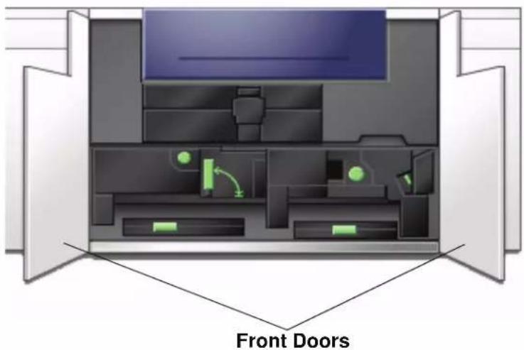
text_image
Front Doors- Grasp handle 4 and move it in the direction of the arrow.

natural_image
Cross-sectional diagram of a mechanical device with internal components and a red arrow indicating direction (no text or symbols)-
Slowly pull out the Paper Transport module until it stops.
-
Clean the chute area as outlined in yellow in the illustration below by wiping it with lint-free cloth:

natural_image
3D rendered mechanical component with a yellow rectangular highlight on a textured surface (no text or symbols)
NOTE: It is recommended that you use the lint-free cloth supplied with your digital press, Xerox part number 19K03610.

TIP: Avoid touching the chute area with your bare hands as this will leave grease and dirt on that area and create paper jams.
- Clean the belts, outlined in yellow:
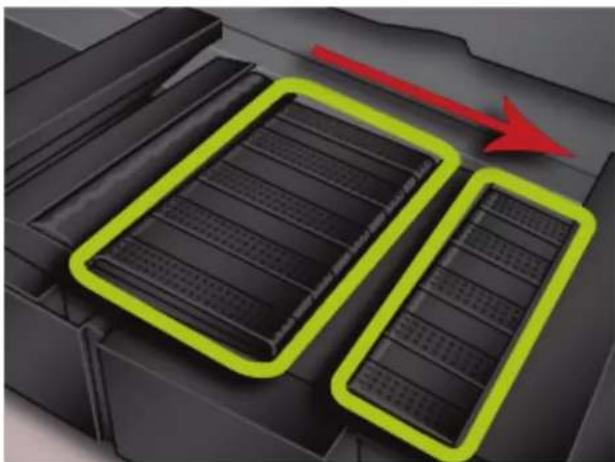
natural_image
Illustration of a battery pack with two black plates and red arrows indicating flow or movement (no text or symbols)
NOTE: It is recommended that you use the lint-free cloth supplied with your digital press, Xerox part number 19K03610.
- Use a lint-free cloth to wipe the belts
- Using the lint-free cloth, rotate the belts in the direction that paper travels; refer to the arrow in the above illustration. Continue to wipe the belts as you rotate them.

NOTE: Do not rotate the belts with your bare hands as this will leave grease and dirt on them and create paper jams. Rotate the belts by using a lint-free cloth.
- Continue to rotate and wipe the belts until all the belts are clean.
- Clean the areas between each belt by wiping them with a lint-free cloth.
NOTE: It is recommended that you use the lint-free cloth supplied with your digital press, Xerox part number 19K03610.
- Clean the sensors (circled below) with a lint-free cloth.

natural_image
3D diagram of a mechanical component with three highlighted circular features (no text or symbols)- Grasp handle 4 and slowly push in the Paper Transport until it stops. Turn the handle in the direction of the arrow to lock the module in place.

natural_image
Cross-sectional diagram of a printer or printer showing internal components and a red arrow indicating a directional flow (no text or symbols present)- Close the right and left front doors.

text_image
Front Doors- Switch on the digital press power.
Cleaning the paper path
Use the following procedure to clean excessive paper dust/fibers from the paper path area.

NOTE: It is recommended that you perform this procedure one time per day, preferably at the start of the day before the digital press is switched on and the fuser is hot.

WARNING: If the digital press is switched on and the fuser is hot, be sure to switch off the digital press power and allow 15 minutes for the fuser to cool before performing this procedure.

CAUTION: Only clean the recommended areas of the paper path as described in this procedure.
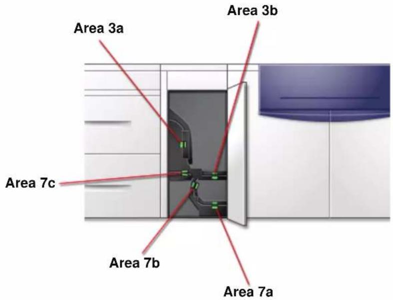
text_image
Area 3a Area 3b Area 7c Area 7b Area 7a
- Use a damp, water moistened (not wet), lint-free cloth to clean the paper path only in the green handle jam clearance areas as shown in the illustration.
a. Open each area and clean both surfaces of the transports. b. Remove any residual moisture with a dry, lint-free cloth.
NOTE: Only perform the following step if your machine has an optional SFM attached. If your machine does not have an optional SFM attached, skip this step and proceed to the next step.

- Use a damp, water moistened (not wet), lint-free cloth to clean the paper path only in the green handle jam clearance areas as shown in the illustration.
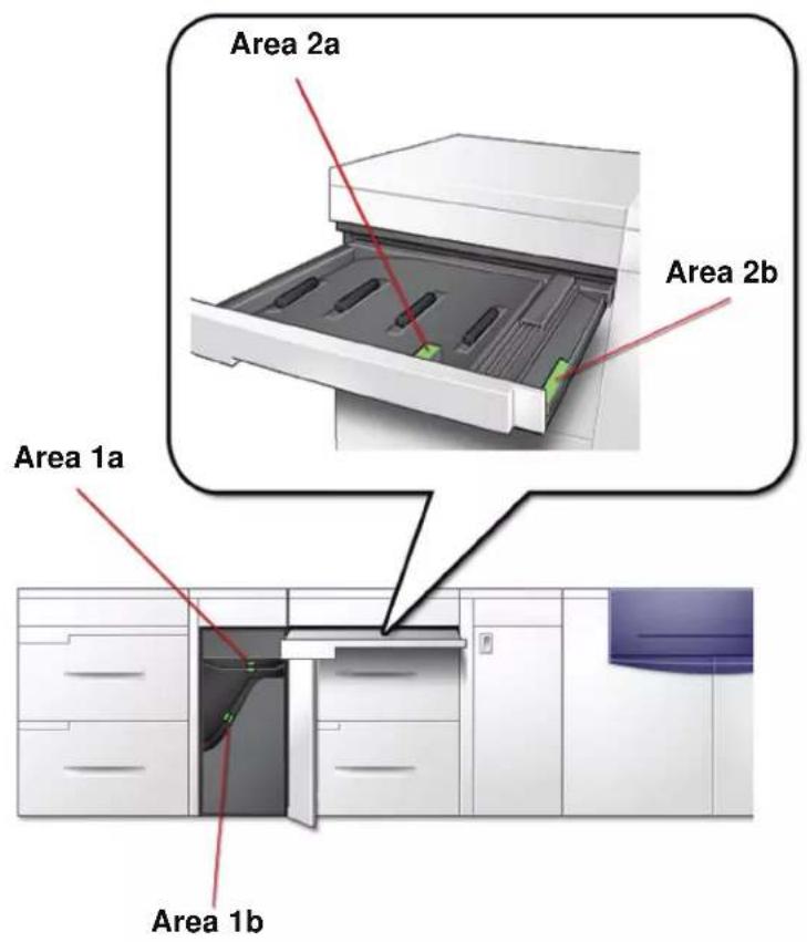
text_image
Area 2a Area 2b Area 1a Area 1b- Use a damp, water moistened (not wet), lint-free cloth to clean the paper path only in the green handle jam clearance areas as shown in the illustration.
a. Open each area and clean both surfaces of the transports.
b. Remove any residual moisture with a dry, lint-free cloth.
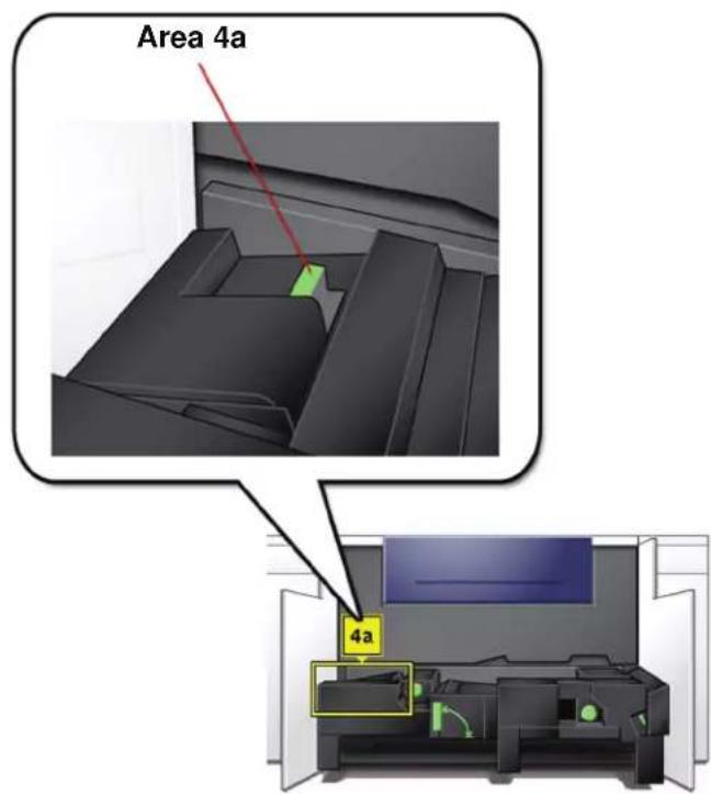
text_image
Area 4a 4a- Use a damp, water moistened (not wet), lint-free cloth to clean the paper path only in the green handle jam clearance areas as shown below.
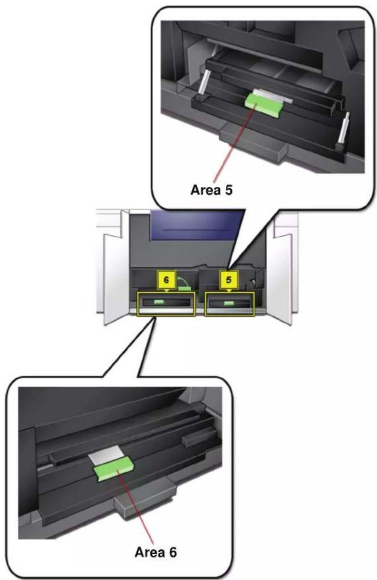
text_image
Area 5 6 5 Area 6- Use a damp, water moistened (not wet), lint-free cloth to clean the paper path only in the green handle jam clearance areas as shown below.

text_image
8a,b,c,d,f 8g- If large amounts of paper dust are frequently observed, contact your Xerox Supplies Representative for an alternate paper recommendation.
NOTE: If Xerox analysis determines that persistent paper contamination is due to cut papers or the use of non-recommended material, the customer may be liable for extended costs outside the scope of the service contract.
Replacing Consumable Supplies
A message is displayed on the UI when a consumable item is nearing the replacement time. Another message is displayed when you must replace consumable items. The digital press will not run after this message is displayed until the item is replaced.
You should keep a supply available of the following consumable items:
• Dry Ink/Toner cartridges in all four colors
- An empty Waste Dry Ink/Toner bottle.
- Fuser Oil
- Fuser Web Assembly
A chart later in this chapter provides the part numbers to order.
Replacing a Dry Ink/Toner Cartridge
Refer to the following procedure when a message to replace a Dry Ink/Toner Cartridge is displayed on the UI. There are also instructions on labels that are affixed to the compartment containing the cartridges.

CAUTION: To prevent spillage, remove Dry Ink/Toner cartridges only when the "Replace the Dry Ink Cartridge" message is displayed on the UI.
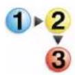
- Place a drop cloth below the Dry Ink/Toner area.
- Open the Dry Ink/Toner Compartment.
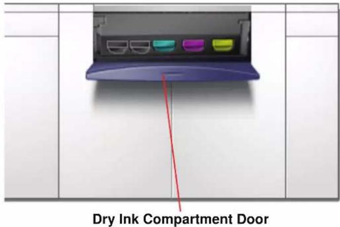
text_image
Dry Ink Compartment Door- Pull the cartridge completely out of the compartment.
natural_image
Illustration of a printer's internal structure with color-coded slots and a green arrow indicating compression (no text or symbols)- Dispose of the empty cartridge according to local regulations.

TIP: Do not use warm or hot water, or cleaning solvents, to remove Dry Ink/Toner from your skin or clothing. This will set the Dry Ink/Toner and make it difficult to remove. If any Dry Ink/Toner gets on your skin or clothing, use a brush to remove it, blow it off, or wash it off with cold water and mild soap.
- Remove a new cartridge from the box.

CAUTION: Dry Ink/Toner settles and compacts during shipping and must be loosened before inserting the cartridge into the machine. Failure to completely loosen the material may cause damage to the gear at the end of the cartridge.

TIP: Vigorously shake and/or slap the new cartridge with your hand until the Dry Ink/Toner is completely loosened. Also, make sure that the gears spin freely.
- Insert the cartridge into the compartment by sliding it into the compartment.
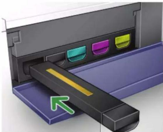
natural_image
Illustration of a printer's internal structure with color-coded slots and an arrow indicating orientation (no text or symbols)
CAUTION: If more than one cartridge needs to be replaced at the same time, ensure that the cartridges are replaced in their correct color locations. From left to right, the cartridge colors are black 1, black 2, cyan, magenta, and yellow.
- Close the Dry Ink/Toner compartment door.
Changing the Dry Ink/Toner Waste Bottle
A message appears on the UI advising you when to replace the Waste Dry Ink/Toner Bottle.
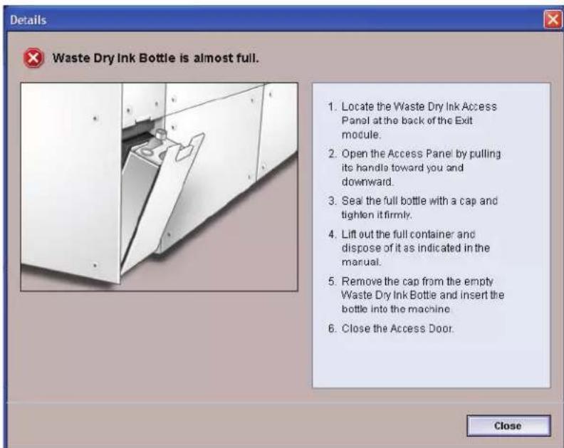
text_image
Details Waste Dry Ink Bottle is almost full. 1. Locate the Waste Dry Ink Access Panel at the back of the Exit module. 2. Open the Access Panel by pulling its handle toward you and downward. 3. Seal the full bottle with a cap and tighten it firmly. 4. Lift out the full container and dispose of it as indicated in the manual. 5. Remove the cap from the empty Waste Dry Ink Bottle and insert the bottle into the machine. 6. Close the Access Door. CloseThe bottle is located at the back of the machine.
- Open the Waste Dry Ink/Toner door at the back of the machine.
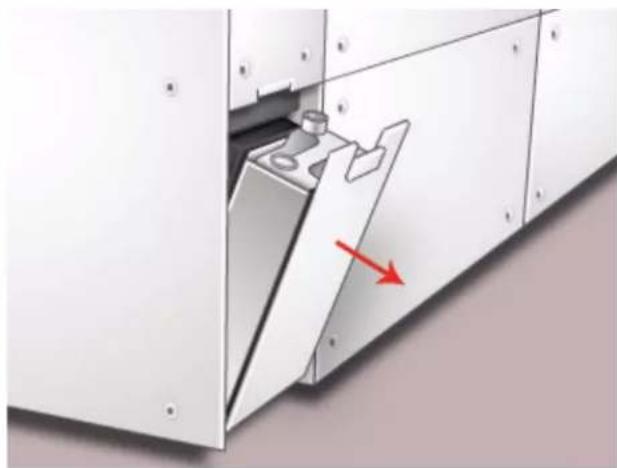
natural_image
Exterior view of a white industrial cabinet with a red arrow pointing to a component (no text or symbols visible)- Grasp the handle of the full bottle and pull it out of the machine.
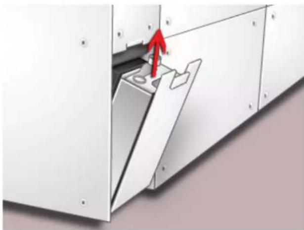
natural_image
Exterior view of a white industrial cabinet with a red arrow pointing to a component (no text or symbols visible)- Remove the cap from the cap holder on the side of the full bottle and press the cap securely into the open hole on the top of the full bottle.
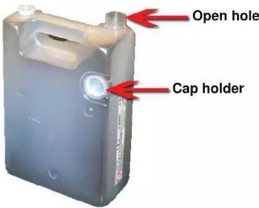
text_image
Open hole Cap holder-
Dispose of the full bottle according to your local regulations.
-
Remove an empty bottle from the carton and insert it into the machine. Ensure that the hole on the top of the bottle is open and facing to the right.
-
Close the Waste Dry Ink/Toner Bottle door.
Adding Fuser Oil
A message appears on the UI advising you when to add Fuser Oil. Use the following procedure to replenish the Fuser Oil supply.
- Open the Right Front Door of the digital press.
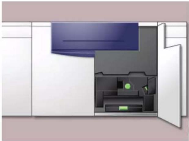
natural_image
Interior view of a modern kitchen appliance with open door and internal compartments (no text or symbols)-
Place a drop cloth on the floor under the Fuser area. Any oil spilled on a hard floor will make the floor slippery.
-
To open the Reservoir Cap, grasp the tab at the back of the cap and pull it forward.
Refer to the following figure for the location of the Fuser Oil Reservoir Cap.
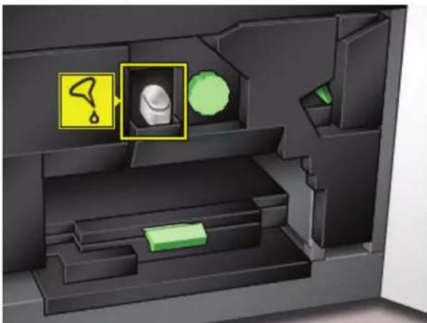
natural_image
Interior view of a computer case with highlighted device and warning symbols (no readable text or labels)- Remove the cap from the bottle of Fuser Oil and replace it with the Filler Spout Cap.
This cap was provided to you when your digital press was installed. Contact your Xerox service representative if you cannot locate the Filler Spout Cap and need another one.
-
Carefully insert the Filler Spout into the opened Fuser Oil Reservoir and squeeze the bottle until the oil reaches the maximum fill level tab visible inside the Reservoir.
-
Remove the Filler Cap from the bottle and place it on a cloth or paper towel to drain. Return the original cap to the bottle of Fuser Oil.
-
Close the Reservoir Cap, ensuring that it snaps into place.
-
Close the Right Front Door of the digital press.
Replacing the Fuser Web Assembly
Two messages will display on the UI regarding the Fuser Web. The first advises you that the web is almost used up and you should be sure to have a new unit on hand. The second message displays when the Fuser Web is completely used and you must replace it. When this message displays, the digital press shuts down and will not print until the web is replaced.
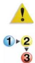
WARNING: The Fuser area is hot. Be careful when working in this area to avoid injury.
Use the following procedure to replace the Fuser Web.
- Open the front doors of the digital press.

text_image
Front Doors- Grasp handle 4 and move it in the direction of the arrow.
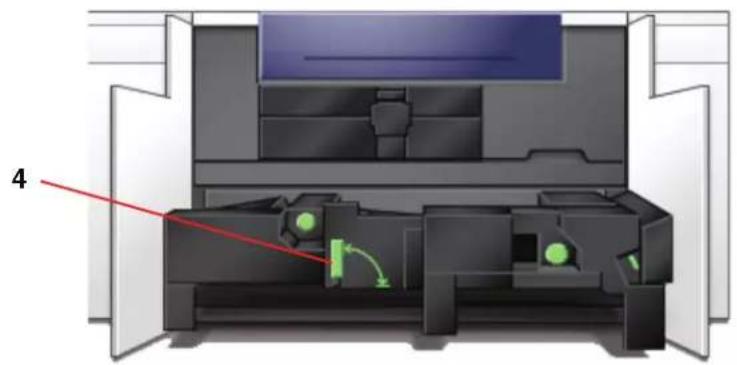
natural_image
Cross-sectional diagram of a printer or printer with internal components and a red arrow pointing to part 4 (no text or symbols present)-
Slowly pull out the Paper Transport module until it stops.
-
Pull open the Fuser handle 4C.
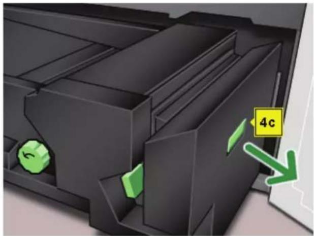
natural_image
3D diagram of a mechanical component with green directional arrows and a label '4c' (no readable text or symbols beyond labels)- Lift up handle 4d until it stops at the top of the Fuser.
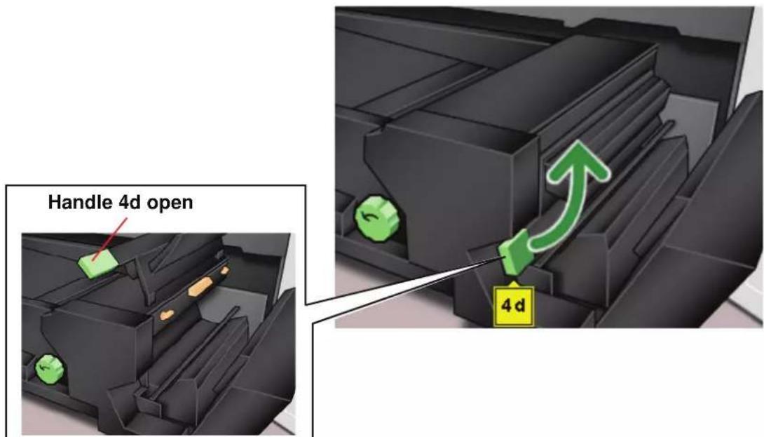
text_image
Handle 4d open 4d- Push down the two levers.

natural_image
3D rendered mechanical component with green arrows indicating motion or flow (no text or symbols)- Grasp the colored handle in the center and pull the web unit down and out of the machine. Dispose of according to your local regulations.
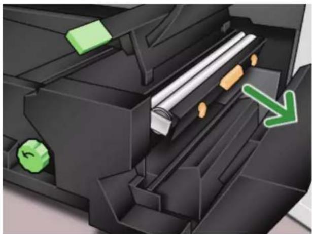
natural_image
Close-up of a mechanical printer internal component with green directional arrows indicating movement or flow (no text or symbols)-
Remove the new web unit from the box and the protective covering.
-
Hold the web assembly with both hands and line up the tabs on both sides of the bottom of the assembly with the slides on both sides of the Fuser area. Slide the assembly in until it is firmly in place.
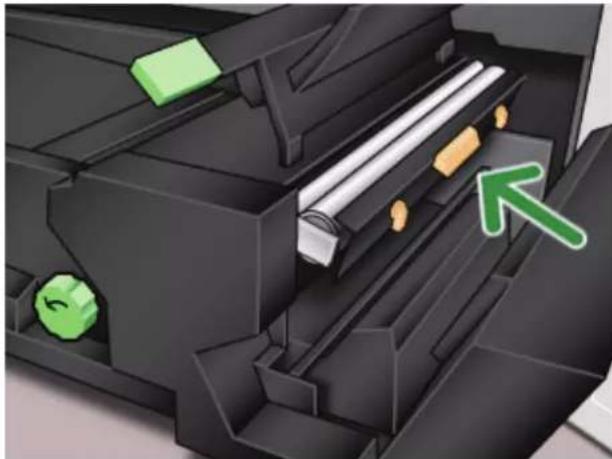
natural_image
3D mechanical assembly diagram showing internal components with green arrows indicating movement or force (no text or symbols)- Raise the unit to the upright position and push up the two orange levers.
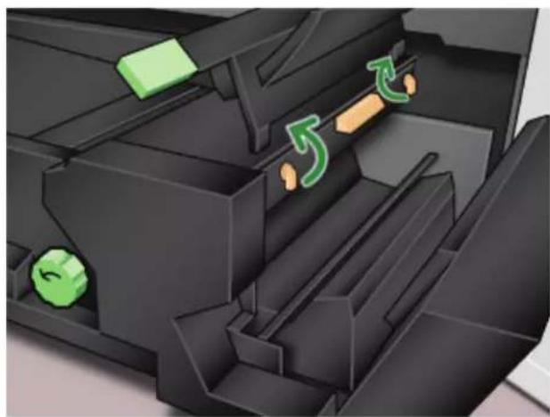
natural_image
3D mechanical assembly diagram showing internal components with green and orange directional arrows (no text or symbols)- Lower handle 4d.

natural_image
3D mechanical assembly diagram showing internal components with a green arrow indicating motion or force (no text or symbols)- Lift up handle 4c and raise the Fuser into its original position.

natural_image
3D illustration of a black plastic enclosure with green directional arrows indicating movement or flow (no text or symbols)- Grasp handle 4 and slowly push in the Paper Transport until it stops. Turn the handle in the direction of the arrow to lock the module in place.
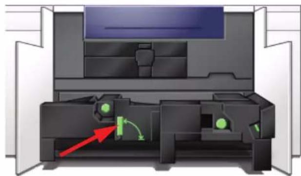
natural_image
Cross-sectional diagram of a printer or printer mechanism showing internal components and directional arrows (no text or symbols)- Close the right and left front doors.

text_image
Front DoorsCalling for Service

Refer to the UI when there is a problem with the digital press or an accessory. A status code and suggested solutions are displayed on the screen. Follow all steps in the suggested solutions until the problem is corrected. If the problem persists, call for assistance.
Follow the instructions below before calling for service.
-
Be prepared to provide a complete description of the problem to the service operator. Defining the problem accurately may help you and the operator solve the problem over the phone and minimize downtime. If the problem cannot be solved by telephone, a service representative will be dispatched to your site promptly.
-
Record the displayed Fault Codes.
-
Record the Machine Serial Number. Press the Machine Status button on the Control Panel. Touch the Machine Details tab and the serial number is displayed. (If the serial number is not displayed, open the Right/Left Front Doors of the digital press. The serial number is also on a white label on the bottom front frame.)
-
If copy quality is a problem, take a copy sample to the telephone with you to help you describe the problem or to assist you when answering the questions from the service operator about the defects.
-
If possible, use a phone near the press when calling for assistance. Follow the instructions provided by the operator.
-
For system support, user help, and service support, call the appropriate number:
US:1-800-821-2797 (Includes TTY support)
Canada:1-800-939-3769
Europe:
Latin America:
Xerox also provides web-based customer support. Go to:
www.xerox.com/eSupportCentre
Consumable Supplies
The following items are consumables for the DocuColor 5000AP. It is recommended that you have a supply of these items available to eliminate downtime when they need to be replaced.
| Supply Item | Supply Number Eastern Hemisphere | Supply Number Western Hemisphere | Supply Unit Shipped with digital press/Reorder Quantity | Approximate Print Yield/Carton (Full Color Prints*) |
| Dry Ink/Toner Cartridge (Black) | 6R1251 6R1247 2/box 22K | |||
| Dry Ink/Toner Cartridge (Cyan) | 6R1252 6R1248 2/box 37K | |||
| Dry Ink/Toner Cartridge (Magenta) | 6R1253 6R1249 2/box 37K | |||
| Dry Ink/Toner Cartridge (Yellow) | 6R1254 6R1250 2/box 37K | |||
| Developer (Black) | 5R711 | 5R711 | 1 | 100K |
| Developer (Cyan) | 5R712 | 5R712 | 1 | 100K |
| Developer (Magenta) | 5R713 | 5R713 | 1 | 100K |
| Developer (Yellow) | 5R714 | 5R714 | 1 | 100K |
| Fuser Oil | 8R13031 | 8R13031 | 1 | 200K |
| *Waste Dry Ink/Toner Bottle | 8R90352 | 8R90352 | 1 | 50k |
| *Black Charge Corotron Unit | 13R596 | 13R596 | 1 | 200K |
| *Fuser Web Assembly | 8R12966 | 8R12966 | 1 | 120K |
| Black Drum Cartridge | 13R617 | 13R613 | 1 | 278K |
| Color Drum Cartridge | 13R620 | 13R616 | 1 | 115K |
| Paper Xerox Digital | Color Colotech+ 90g/m2(24 lb) | Xerox Digital Color Xpressions+ 90g/m2(24 lb) | 2 reams | |
| Staple cartridge (for optional CSS) | 8R12799 8R12799 | 1 box of 3 | cartridges |
* Please call your Xerox service representative to reorder Waste the Dry Ink/Toner Bottle, the Fuser Web Assembly, The Black Charge Corotron, and the Drum Cartridges. These parts are provided to you at no charge when ordered by a Xerox service representative.
Store supply items and Xerox parts in their original packages in a convenient location.
* Dry Ink/Toner yield projections are based on 15 percent area coverage per color (4 colors = 60 percent) at standardized conditions on A4 (8.5x11") Xerox Digital Color Xpressions+, 24 lb. (90 g/m²) and Colotech Plus 90 g/m² reference paper.
NOTE: Actual yields vary greatly, depending on color intensity, area coverage, paper stock, and run mode selected.

To order consumable supplies, call the appropriate number:
US:1-800-822-2200
Canada: French: 1-800-668-0133, English: 1-800-668-0199
Europe:
Latin America:
