WorkCentre Pro 555 - Printer XEROX - Free user manual and instructions
Find the device manual for free WorkCentre Pro 555 XEROX in PDF.

User questions about WorkCentre Pro 555 XEROX
0 question about this device. Answer the ones you know or ask your own.
Ask a new question about this device
Download the instructions for your Printer in PDF format for free! Find your manual WorkCentre Pro 555 - XEROX and take your electronic device back in hand. On this page are published all the documents necessary for the use of your device. WorkCentre Pro 555 by XEROX.
USER MANUAL WorkCentre Pro 555 XEROX
WorkCentre Pro 555/575 User's Guide
natural_image
Exterior view of a beige and black printer with control panel (no visible text or symbols)708P84301
Xerox Limited,
Global knowledge and Language Services,
Enterprise Centre,
Bessemer Road,
WELWYN GARDEN CITY,
AL7 1HL
United Kingdom
©2000 by Xerox Corporation. All rights reserved.
Xerox®, Xerox Limited® and all the products mentioned in this publication are trademarks of Xerox Corporation and Xerox Limited.
Products and trademarks of other companies are also acknowledged.
Copyright protection claimed includes all forms and matters of copyrightable material and information now allowed by statutory or judicial law or hereinafter granted, including without limitation, material generated from the software programs which are displayed on the screen such as icons, screen display looks, etc.
Changes are periodically made to the document. Revisions, changes, any technical inaccuracies, and typographical errors will be corrected in any subsequent editions
Table of Contents
Chapter 1 How to Use This Manual....1-1
Finding Information in the User's Guide 1-1
Information provided by the Advanced Features Guide (AFG) ......1-2
Document Conventions 1-3
Notes, Cautions, and Warnings....1-4
Chapter 2 Introduction......2-1
System Overview....2-1
System Features 2-2
Hardware Features....2-4
System Requirements 2-6
Space Requirements....2-7
Control Panel....2-8
Control Panel Components and Function Keys....2-9
Direct Access Function Keys....2-13
Tones....2-14
Operation Modes....2-15
Standby Mode 2-15
Communication Mode....2-15
Copy Mode 2-16
Menu Mode....2-16
PC Printing Mode 2-16
Chapter 3 Getting Started....3-1
Printing a Menu Map 3-1
Setting the Machine Language....3-2
Setting the Date and Time....3-3
Setting your Machine ID* 3-6
Setting the Dial Mode ^* 3-8
Setting the Send Header....3-9
Setting the Receive Footer....3-10
Loading Paper....3-11
Bypass Tray: 3-11
Paper Tray: 3-13
Setting the paper size....3-16
Loading Documents 3-17
Document Specifications....3-17
Selecting the Scan Resolution 3-19
Selecting the Scan Contrast....3-20
Quick Start....3-21
To Receive 3-21
To Send....3-21
To Copy 3-21
To Print....3-21
Phonebook Reports....3-22
Speed Dial Phonebook 3-23
One Touch Phonebook....3-24
Group Phonebook....3-25
Alphabetical Phonebook ....3-26
Chapter 4 Basic Troubleshooting....4-1
Paper Jam 4-1
Document Jam 4-12
Appendix A Safety Certification and Environmental Compliance.....A-1
Laser Safety Information ...... A-3
Third Party Certification.... A-4
Radio Frequency Emissions USA A-4
European Certification.... A-6
Approvals and Certification.... A-6
UK Electricity at Work Regulation...... A-7
Environmental Compliance.... A-10
ENERGY STAR® A-10
Environmental ChoiceM A-10
SWISS ENERGY 2000....A-11
Recycled Paper A-11
Telecommunications Requirements ...... A-12
Fax Approvals and Certification.... A-12
FCC Regulations A-13
Send Header Requirements.... A-13
Data Coupler Information A-13
Canadian Certification A-15
1 How to Use This Manual
Thank you for purchasing the Xerox WorkCentre Pro. The WorkCentre is designed for ease of use, but to use your machine to its fullest potential, take some time to read the User Documentation.
You will be ready to send and receive faxes and make copies with your machine as soon as you have read chapters 1 through 3. You can then refer to topics in the remaining documentation as needed.
Finding Information in the User's Guide
The User's Guide contains the following sections:
Table of Contents
Use the Table of Contents to find topics easily.
How to Use This Manual - Chapter 1
Describes the information in this User's Guide and Advanced Features Guide.
Introduction - Chapter 2
Describes the system and hardware features of the machine and provides an overview of how the machine operates. Each key on the Control Panel is described.
Getting Started - Chapter 3
Includes the procedures for setting up the basic machine information such as date, time, language, machine ID, send header and receive footer. Simple instructions to send, receive, print, and copy are also provided.
How to Use This Manual
Basic Troubleshooting - Chapter 4
Guides the user through problem solving, and recommended corrective actions.
Environment Specifications - A
Provides the safety, data coupler, and Canadian certification information.
Index
Refer to the Index to locate specific information.
Information provided by the Advanced Features Guide (AFG)
- Programming the Machine
- Receiving Documents
- Dialling Methods
- Transmitting Documents
- Cancelling Jobs
- Polling
- Mailbox Communications
- Reports
- Printing Functionality
- Control Centre/PC Interface Guide
Document Conventions
A document convention is simply a way of presenting information. This section explains the conventions used in the WorkCentre Pro User's Guide.
Many procedures require you to press a key to perform a function; these keys appear in boldface type.
For example: Press Start to send a fax.
When you use the Menu Mode, you may have to press a series of keys before arriving at the desired menu. The resulting screen message for each step appears next to the series of keys pressed.
For example: The procedure to enable the Send Header would appear as follows:
To enable the send header:
- Press:


Send header 1. Inside
2.Outside 3.Off
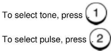
- Select where you want the fax header to be printed:
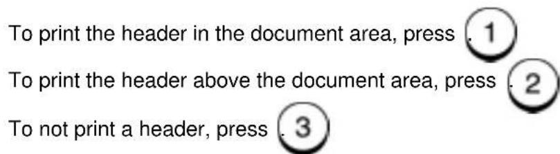
text_image
To print the header in the document area, press . 1 To print the header above the document area, press . 2 To not print a header, press . 3- The menu selection screen redisplays. Press to return to the Standby Mode.
Exit() or Stop
Notes, Cautions, and Warnings
This manual uses notes, cautions, and warnings to emphasize information the reader needs. Notes contain information that supplements the text. Notes are emphasized with italics. The following is an example of a note:
Note: Notes are provided as additional information.
The following are examples of a caution and a warning:

CAUTION
Do not touch the green drum surface. Touching the drum could reduce the print quality.

WARNING
Used to alert users to risk of personal injury.
2 Introduction
This chapter provides an overview of the WorkCentre's hardware features and operation. The Control Panel is discussed and each key is defined.
System Overview
The WorkCentre allows the user to send, receive, copy, and print documents. The ControlCentre software allows you to program the Fax settings on a PC and write the settings to the WorkCentre.
When you switch on the power and the system has warmed up, the machine is in the standby, or idle mode and is ready to use. When an action completes successfully, the machine returns to the Standby Mode and displays the following information:
Jan-31 Mon02:23p100% Auto answer
Through the Menu mode, you can configure the standard machine settings or customize your machine. Refer to Chapter 3 "Getting Started" for basic programming instructions and procedures for setting the standard machine settings.
For optimum performance, the machine should be left on 24 hours a day. While the machine is powered on, the internal batteries are charged. (for 575 only)
The primary battery retains the programmed data for up to 5 years if the machine loses power.
Document data stored in a machine with standard memory is retained for up to 72 hours during a power failure or power off, where the image battery is fully charged for more than 8 hours prior to power off. (for 575 only)
The following table describes many of the WorkCentre features.
Refer to the Table of Contents or Index to locate detailed information.
| Feature Description | |
| Copying on Plain Paper Plain paper is used for printer output thereby allowing the use of standard forms, labels, etc. | |
| Alpha Dialing555: 145 Numbers575: 238 Numbers | Dial the desired location by searching for the name in the Speed Dial, One Touch, and Group phonebooks. |
| One Touch Dialing555: 20 Keys575: 38 Keys | With one key stroke, the number of the assigned location(s) is dialed and the document is sent. |
| Speed Dialing555: 100 Numbers575: 150 Numbers | In addition to the 20/38 One Touch keys, 100/150 3-digit speed dial numbers can be assigned to frequently called locations. |
| Direct Access Function Keys(5 Keys) | Five of the most frequently used functions are assigned to keys located on the Access Panel. |
| Multi Access Communications | Utilizing the built-in memory, as many as 100 operations can be programmed for maximum equipment utilization and efficiency. For example, you can store a document to memory while the machine is receiving a document. |
| High Resolution With a maximum resolution of 406 dots/inch x 392 dots/inch(16 dots/mm x 15.4 lines/mm) and 64 levels of halftone expression, precision drawings, small-size characters, or photographs are copied, sent, and received clearly. | |
| Enriched System Functions Various types of communications are available through enriched system functions such as Relay, Group, and Mailbox Communications. | |
| Mailbox Systems Features ITU-T industry standards mailbox communications. | |
| Group Communications555: 25 Groups575: 50 Groups | This feature allows the transmission of a document to as many as 120/188 different remote locations with one operation sequence. |
| Manual Group This feature allows the user to send a document to multiple remote machines by simply pressing the Manual Group key and entering the telephone numbers. | |
| Batching This feature automatically performs transmissions of multiple documents going to the same phone number. Documents sent to the same location are transmitted with one phone call, thus saving time and call connecting costs. | |
| Refuse Junk mail With this feature selected, your WorkCentre only receives from those remote units with phone numbers assigned to your Speed Dial or One Touch phonebooks. | |
| Receive to Memory Automatically stores up to 100 received documents to available memory if the paper runs out or if a paper jam occurs. | |
| Collated Fax With this feature selected, incoming documents are received to memory and then printed “last page first”. This feature stacks the document with page 1 on top. | |
| Super Power-Saver Mode This feature turns off areas of the machine, which have a high power consumption. | |
| Printer Power Saver Mode This feature turns off the printer fuser unit to reduce the power consumption. | |
| Optional Accessories The Work Centre can be optioned with an additional paper cassette, and a handset*. | |
| ControlCentre | ControlCentre is software package that can be loaded on a PC. The ControlCentre software allows you to program most of the machine settings using the PC, then write the settings to the WorkCentre. |
| PC Printing | With the Windows Printer Driver installed on your PC and the parallel print cable attached to the parallel port, the WorkCentre can be used to print from the PC. |
* Not available in all markets.
Hardware Features
| Feature Description | |
| Document Output Tray Collects the document pages following a transmission or copy operation. Contains an extension to support legal documents. | |
| Control Panel Contains the keys to program system features or operate the machine. | |
| Document Guides Guides the document pages into the scanner. | |
| Document Support Supports the documents to be copied or transmitted. | |
| Handset Connector* Provides a jack for connecting the optional handset. | |
| Telephone Connector* Provides a standard modular jack for connecting a telephone. | |
| Line Connector A standard modular jack for connecting the phone line for fax communications. | |
| Top Cover Open Button Releases the Top Cover for accessing consumables or clearing a paper jam. | |
| Paper Tray Supplies the cut sheet paper to the WorkCentre. | |
| Copy Output Tray | Collects printed documents. |
| Power Switch Switches the WorkCentre power On/Off. | |
| Power Cord | Supplies power to the machine. |
| Bi-directional Parallel Connector (IEEE 1284 compliant) | Connects the WorkCentre to a PC. |
* Not available in all markets.
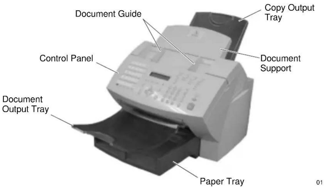
WorkCentre Hardware Features
text_image
Document Guide Control Panel Document Output Tray Paper Tray Copy Output Tray Document Support
text_image
HANDSET* TEL* LINE Top Cover Open Button Bi-directional Parallel Connector Power Cord Connector Power Switch* Not available in all markets.
System Requirements
When choosing an installation location, follow these guidelines:
- Avoid dusty locations, extreme heat, humidity, direct sunlight, or areas subject to heavy vibration.
- Avoid areas where interference from other electrical devices may be present.
- Avoid using an AC outlet that shares the same circuit as an electrical device, which may create interference.
- Locate the machine within reach of a telephone outlet. Use a dedicated single line telephone connection.
- Place the machine on a level surface. An uneven surface can cause performance problems such as poor copy quality and paper jams.
Space Requirements
Adequate space is required for ventilation, ease of operation, maintenance, and replacement of consumables. Provide the minimum space as shown in the following figure.
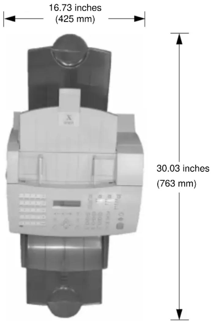
text_image
16.73 inches (425 mm) 30.03 inches (763 mm)Width (with Handset): 19.43 inches (493.5 mm)
Height: 17.13 inches (435 mm)
Height (with Optional Paper Cassette): 22.28 inches (566 mm)
Control Panel
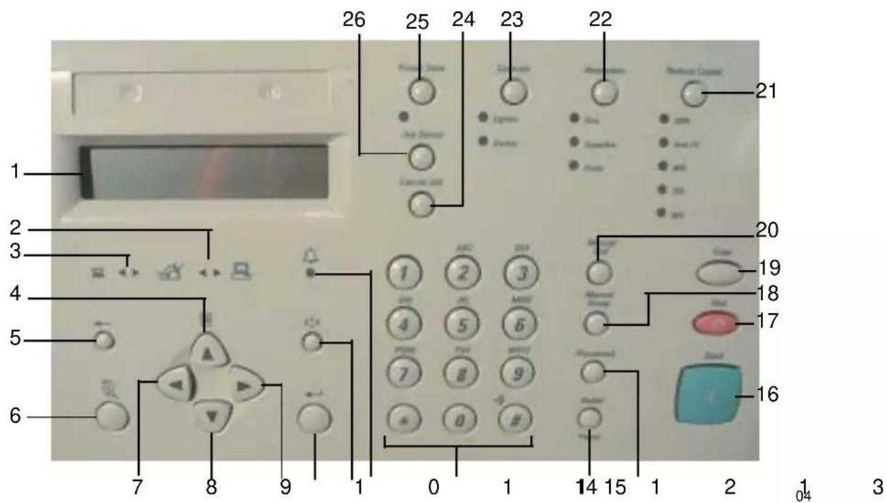
text_image
1 2 3 4 5 6 7 8 9 1 0 1 26 25 24 23 22 21 20 19 18 17 16 14 15 1 2 3 4 5 6 7 8 9 0 1 Control unit Circuit Control Circuit Control Circuit Control Circuit Control Circuit Control Circuit Control Circuit Control Circuit Control Circuit Control Circuit Control Circuit Control Circuit Control Circuit Control Circuit Control Circuit Control Circuit Control Circuit Control Circuit Control Circuit Control Circuit Control Circuit Control Circuit Control Circuit Control Circuit Control Circuit Control Circuit Variable Circuit Variable Circuit Variable Circuit Variable Circuit Variable Circuit Variable Circuit Variable Circuit Variable Circuit Variable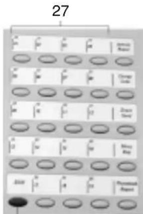
text_image
27 10 11 12 13 14 15 16 17 18 19 20 21 22 23 24 25 26 27 28 29 30 31 32 33 34 35 36 37 38 39 40 41 42 43 44 45 46 47 48 49 50 51 52 53 54 55 56 57 58 59 60 61 62 63 64 65 66 67 68 69 70 71 72 73 74 75 76 77 78 79 80 81 82 83 84 85 86 87 88 89 9028
Control Panel Components and Function Keys
The Control Panel is used to program the features and to initiate communications. The following figures and tables illustrate the Control Panel and describe each component.
| Item | Description Function | |
| 1 | Display Displays the machine status and messages. The display provides information about the current operation mode. The machine has the following operating modes: Standby Mode, Communication Mode, Menu Mode, Copy Mode, PC Printing Mode, (see “Operation Modes” later in this Chapter). | |
| 2 | PC LED Illuminates when a PC communication is in progress. | |
| 3 | Line LED Illuminates when a fax communication is in progress. | |
| 4 | The  | Menu key is used to access menu items listed in the menu map which are not available from the direct access keys. The Menu key is also used as a navigation key for scrolling up a menu list. |
| 5 | Delete the character at the position of the cursor. | |
| 6 | Used to Exit or *  | Exit a menu list. |
| 7 |  | Left or Back navigation key used for going back to a previous menu list. Also used for positioning the cursor for character delete or insert when you enter names. |
| 8 |  | Down navigation key used for scrolling down a menu list. |
| 9 |  | Right navigation key used for going to the next level of menus of the highlighted item. Also used when you enter names for positioning the cursor for character delete or insert. |
* Symbol used on International machines.
Introduction
| Item Description Function | ||
10 Used to select the dis Enter or  | displayed menu item, to start a communication, or to accept name and number entries.*Used on International machines. | |
11 Sets the insert mode al Insert or  | allowing a character to be inserted at the position of the cursor instead of overwriting the character in the current position.*Used on International machines. | |
| 12 Alarm LED * Illuminates when an error occurs, or when the machine is out of paper, toner or drum. | ||
| 13 Numeric Keypad | Used for numeric, alphabetical or special character input for direct dialing, directory dialing, and menu item input. | |
| 14 During on-hook or off-hook dialing, this key is used to redial the last number dialed. Pressing Redial/Pause displays the jobs waiting to be redialed. Pressing the Enter key forces an immediate redial.When entering a telephone number, pressing this key enters a pause in the telephone number sequence. | ||
| 15 Used to access program Phonebook | rammed Speed Dial, Alpha, and/or Groups. Pressing this key initially displays the phonebook menu. | |
| 16 Starts a job that is ready for transmitting, scanning, or copying. | ||
| 17 Stops a Direct Send stop | job and ejects the document from the scanner. Also used to clear an error message displayed on the display. | |
* Used on International machines.
| Item Description Function | ||
18 Used to create a one Manual Group  | time group of phone numbers, for Group Sending or Polling. Speed dial and one touch numbers can be used. | |
19 Used to copy documents  | ||
| 20 |   | Used for interactive dialing. Digits are dialed as the key is pressed. The line monitor automatically turns on. |
21 Used to set the copy Reduce Copies  | reduction. The following settings are available: 100%, Auto Fit, 86%, 75%, 50% | |
22 Used to set the resolution  | ution for copying, scanning, or faxing. The following settings are available: Standard (no LED lit, fax only), Fine, Superfine, Photo. | |
23 Sets the contrast of the Contrast  | the printout to Normal (no LED lit), Lighten, or Darken. This is a scanner setting affecting send and copy. | |
24 Deletes pending and Cancel Job  | active jobs. You must select the appropriate job type to display the desired job for cancellation. Once the job is displayed, pressing Cancel Job again displays the Cancel Job Confirmation screen.When used in conjunction with the Job Status key, active jobs can be canceled quickly by pressing this key then confirming the cancellation. | |
| 25 This feature was power off to minimize power consumption, if the machine has not been used for a period of time. | ||
Introduction
| Item Description Function | ||
| 26 | Displays the active jobJob Status[zcws] | Job if a communication is in progress. If there are no communications in progress, a summary of the Pending Jobs is displayed. |
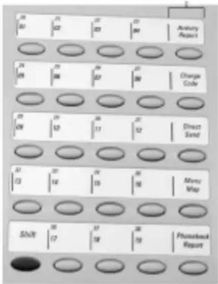
| 27 | One Touch Keys | Used to select phone numbers that have been stored in memory. |
| 28 | Shift Key(for 575 only) | Used to select one touch numbers form 20 to 38 and for case character changes on the letter keyboard. |
Direct Access Function Keys
The following table lists the WorkCentre's Direct Access Function Keys which are located in the left of the Control Panel. The Direct Access Function Keys automate 5 of the most frequently used WorkCentre features.
Direct Access Function Keys
text_image
Annuity Report Charge Code Direct Send Mems Map Phonsetback Report06
Refer to the Table of Contents to locate specific function information.
| Description | Function |
Activity Report | Prints a list of Transmission Communications, Receive Communications, or both. |
Charge Code | Allows entry of a Charge Code at the time of dialing or during phonebook programming. Digits entered after this selection are concealed. |
Direct Send | Transmits the document directly from the scanner instead of scanning it into memory first. |
Menu | Prints out a menu listing with the menu address numbers. |
Phonebook Report | Prints a list of telephone/facsimile numbers stored in memory. Available reports include Alphabet, Speed Dialing, One Touch, and Group Dialing numbers. |
Tones
The WorkCentre generates tones to indicate the operational status of the machine.
- Single short tone — A confirmation tone. A short tone sounds when a key is pressed or when an action completes successfully.
- Extended tone — Signifies an unsuccessful operation. An extended tone (two to five seconds) occurs when a transaction does not complete normally. The user must perform an action to continue a process. Refer to the display messages in the Advanced Features Guide.
Standby Mode
When the machine is in the Standby Mode, the display indicates the machine status, a prompt for the next operation, or an error message. The following information is displayed:
- Date and time — The month, day and time (hour and minute) are displayed. Use the Menu Mode to set the date display sequence and the time format.
- Standby Mode Status — The Standby Mode Status indicates the Reception Mode (“Auto Answer”, “Manual Answer”, “TEL/FAX”, “FAX/TAD”). If “Reception Mode” is displayed, the machine has completed the previous task and is ready to fax or copy. If the Paper Tray becomes empty or open, the Standby Mode Status is replaced with the Paper Tray status (Error Message).
Enter Depart. code — if dept. code feature is enabled.
- Free Memory — The percentage of remaining memory available for storing documents is displayed. If no memory is used, 100% is displayed.
Communication Mode
- Memory Send — Memory send communications are performed in the background.
- Direct Send — The status of a Direct Send operation is displayed.
- Communication results — Results of a communication can be printed. (Refer to the Advanced Features Guide.)
- Communication error code — The result of an error in a communication. (Refer to the Advanced Features Guide.)
Copy Mode
When the machine is in the Copy Mode, the display informs about the machine status as the machine prints single or multiple copies of the document. When in the copy mode, the following information is displayed. The display changes in the following order each time you

- The displays indicates Copying.
• Collate Feature — Collate On/Off
• Paper tray — 1st/Bypass/2nd* - Copies
* Optional Paper Cassette
Menu Mode
When the machine is in the Menu Mode, the display indicates each programmable feature, and the settings selected. As you scroll through the menu, the machine prompts you for the information necessary to program each feature.
Several of the features accessed through the Direct Access Function Keys also use menu access.
For a complete overview of the programmable features, refer to the Menu Flow Map in the Advanced Features Guide on your CD-ROM.
PC Printing Mode
Using the ControlCentre software and appropriate printer drivers, the WorkCentre can communicate with your PC to allow PC printing and programming of features.
This chapter contains step-by-step procedures to program the basic machine settings and set up the most commonly used facsimile features. To get you started quickly, basic steps to send, receive, and copy a document are also provided.
For additional setup functions, refer to the appropriate Advanced Features Guide chapter.
Printing a Menu Map
The Menu Map is a list of all machine features in a flow chart format. Refer to Advanced Features Guide.
To print the Menu Map:
- Press:
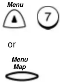
text_image
Menu 7 Or Menu Map- The Menu Map prints, then the machine returns to the Standby mode.
Setting the Machine Language
The WorkCentre is capable of displaying and printing in various languages.
Note: Available Languages may vary depending on your location. If not available, "Not Allowed Now" will display.
To change the machine language:
- Press:


flowchart
graph TD
    A["Language\n01.Espanol"] --> B["02.English"]
    B --> C["03.Portugues"]
    C --> D["04.Francais"]
- Use the Numeric Keypad to select the desired language, then press Enter.
The menu selection screen redisplays. Press Stop to return to the Standby Mode.
Setting the Date and Time
The WorkCentre shows the date and time in the display when in the Standby Mode. The date and time information is used by the internal clock to start delayed jobs and record data on faxes and reports. In addition, you can program the WorkCentre to print the date and time on documents that you send and receive.
For more information on printing the date and time on your documents see “Setting the Send Header” and “Setting the Receive Footer” later in this chapter.
To set the Date & Time:
- Press:

Date [01-31-2000]
- Using the Numeric Keypad and the arrow keys, enter the date, then press Enter

text_image
Date format 1.MM-DD-YYYY 2.DD-MM-YYYY 3.YYYY-MM-DDGetting Started
- Select the Date format.
To display the date in the order of Month/Day/Year (4-digit),
press 1.
To display the date in the order of Day/Month/Year (4-digit),
press 2
To display the date in the order of Year (4-digit)/Month/Day,
press 3.
Month format
1.Numeric
2.Name
- Select the Month format.
To display the Month number, press .1
To display the abbreviated Month name, press
2
Time format?
1.24 hour
2.12 hour
- Select the Time format:
To select 24 hour format, press
To select 12 hour format, press

Time
[10:30 pm]
or
Time
[22:30 pm]
- Using the Numeric Keypad and arrow keys, enter the time, (if necessary, use the arrow key to set AM/PM), then press Enter.
The menu selection screen redisplays. Press Exit or Stop to return to the standby mode.
Setting your Machine ID\*
The Machine ID identifies your machine to the remote machine when they communicate. The Machine ID must identify the person or company that sends the documents and appear on each transmitted page.
Note: For assistance entering alpha or Special Characters, refer to the Advanced Features Guide.
Note: U.S. Regulations require that your fax transmittals include your name (business or individual), telephone number, date, and time.
To set your Machine ID:
- Press:

| Name | (40 max) |
| [ _ ] | |
- Using the Numeric Keypad and the Character Code Table in Chapter 3, enter your identification name and press Enter.
| Country code1.Yes |
| 2.No |
Note: If 1 is selected, the “+” symbol is automatically displayed at the beginning of the fax telephone number indicating a Country Code can be entered. If 2 is selected, international communication can be entered manually when dialing.
- Select the Country Code option:
To enter a Country Code, press
To skip entering a Country Code, press


Fax number (20 max)
[ ]
- Using the Numeric Keypad, enter the machine telephone number then press Enter.
Note: Press the Right arrow key to insert a space.
The menu selection screen redisplays. Press Exit or Stop to return to the Standby Mode.
Setting the Dial Mode\*
Your machine must be set to the dialing mode compatible with your telephone line requirements. The Dial Modes supported are tone and pulse. Pulse is sometimes referred to as rotary dial.
If your machine is connected to a PBX system, you may need to enter a number to access the outside telephone line.
To set the Dial Mode:
- Press:

text_image
Menu 5 1 0 9Dial mode
1.Tone
2.Pulse
- Select the Dial Mode.
text_image
To select tone, press . 1 To select pulse, press . 2Call number (10 max)
[ ]
- Enter the number required to access an outside line, then press Enter. (If no number is required, press Enter.)
The menu selection screen redisplays. Press Exit or Stop to return to the Standby Mode.
Setting the Send Header
With this feature enabled, your Send Header information is printed at the top of each page you send. When enabling the Send Header feature, you can specify where the header is to be printed "inside" or "outside" the document data area. If "Inside" is selected and sending data exists near the top edge of the paper, the header information and data may overlap. If "Outside" is selected, the header information is printed at the top of the page and the document is printed below to avoid overlapping.
The following information is printed on the Send Header:
- Date
- Start Time
• Transmitting Station ID (department, name & telephone number) - Transmission Serial Number - The machine automatically assigns a three digit number. This number is used on confirmation reports or error reports.
• Page Number/Total Number of Pages - Job or File Number
To enable the Send Header:
- Press:


flowchart
graph TD
    A["Send header\n1.Inside"] --> B["2.Outside"]
    B --> C["3.Off"]
Getting Started
- Select where you want the fax header to be printed.
To print the header in the document area, press

To print the header above the document area, press

To not print a header, press

The menu selection screen redisplays. Press Exit or Stop to return to the Standby Mode.
Setting the Receive Footer
A Receive Footer option is available which enables the WorkCentre to print a receive footer on each received page.
The Receive Footer displays the following information:
- Footer Message
- Date
- Start Time
• Transmitting Station ID - Receiving Station ID
- Page Number
To enable the Receive Footer:
- Press:

text_image
Menu 5 4 0 7Receive footer 1.On
2.Off
- Select the Receive Footer option:
To enable the Receive Footer, press

To disable the Receive Footer, press

The menu selection screen redisplays. Press Exit or Stop to return to the Standby Mode.
Loading Paper
Load paper into the WorkCentre paper trays using the following procedures:
Bypass Tray:
- Raise the Document Output Tray and open the Paper Guide.
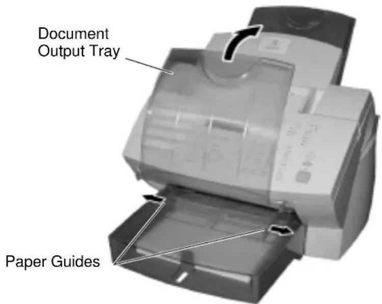
text_image
Document Output Tray Paper Guides01
- Insert one sheet of paper into the Bypass Tray.

text_image
Papern2
Getting Started

CAUTION
Do not insert more than one sheet of paper into the Bypass Tray.
It will cause a paper jam.
-
Adjust the Paper Guides so that both sides of the paper are secure.
-
Lower the Document Output Tray.

text_image
Document Output Tray Paper GuidesPaper Tray:
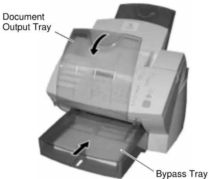
- Raise the Document Output Tray and remove the Bypass Tray.
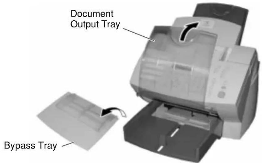
text_image
Document Output Tray Bypass Tray04
- Open the Paper Guides.
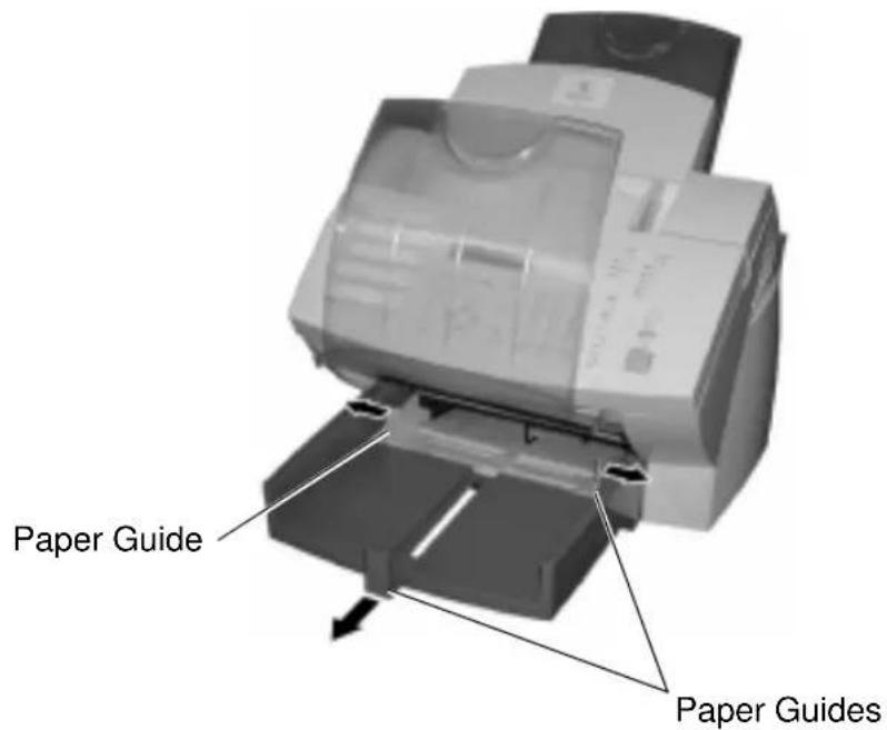
text_image
Paper Guide Paper Guides05
Getting Started
- Do not fan the paper. Make sure that the corners of the paper are neatly aligned.

natural_image
Line drawing of two hands holding a flat object, no text or symbols present06
- Insert up to 250 sheets into the Paper Tray. Secure the stack by adjusting the Paper Guides.
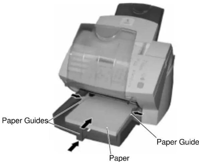
text_image
Paper Guides Paper Paper Guide07

CAUTION
To avoid paper jams, do not exceed the upper limit line on the Paper Guides.

text_image
Paper Guide Upper Limit LineReplace the Bypass Tray and lower the Document Output Tray.
text_image
Document Output Tray Bypass Tray09
Setting the paper size
- Press:

text_image
Menu 5 2 0 3Paper size (Tray1) 1.LT
2.A4 3.LG
- Select the paper size:
To select Letter size paper, press

To select A4 size paper, press

To select Legal size paper, press

- The menu selection screen re-displays. Press return to the Standby Mode.
Exit or Stop to
Note: When the Optional Paper Tray is installed, the following screen appears after selecting the paper size Step 2.
Paper size (Tray2) 1.LT
2.A4
To select Letter size paper, press

To select A4 size paper, press

Then go the Step 3.
Loading Documents
The Document Support holds up to 30 documents for transmitting or copying. Refer to the following size specifications for the range of documents that can reliably scan through the machine. If a document does not meet these specifications, make a copy on a copier using an accepted paper size, then insert the copied image in the Document Tray.
Document Specifications
The following table lists the sizes, types, and quantities of paper that can be loaded into the Document Feeder for copying or faxing.
| Single Sheet Multiple | Sheets | |
| Max. Document Size | 8.5 in. (W) x 14 in. (L)[216mm (W) x 356mm (L)] | Same as Single Sheet |
| Min. Document Size | 5.8 in. (W) x 3.9 in. (L)[148mm (W) x 100mm (L)] | Same as Single Sheet |
| Effective Scanning Width | 8.5 inches[216 mm] | 8.5 in. (W) x 14 in. (L)[216mm (W) x 356mm (L)] |
| Max. capacity of the Document Feeder | N/A 30 sheets | (Letter/A4 size, 20 lbs)15 sheets(Legal size, 20 lbs) |
| Weight of Paper Stock | 52.6 g/m2 to 120 g/m2(14 lbs to 32 lbs) | 60 g/m2 to 100 g/m2(16 lbs to 28 lbs) |
Avoid the following types of documents which can cause jams:
- Torn, wrinkled, curled, or folded sheets
• Sheets with punched holes - Transparencies
• Sheets with paper notes attached - Coated or shiny sheets
• Carbon or carbon backed sheets - Envelopes
Getting Started
To load documents:
Load the document face down in the document support. Adjust the document guide to fit the width of the document. Angle the stack to optimize feeding performance. To cancel a document in the ADF, press Stop.
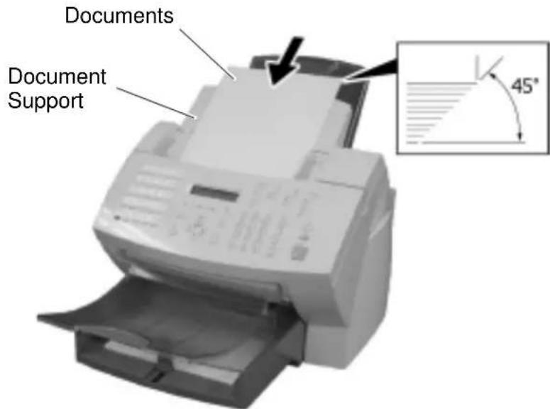
text_image
Documents Document Support 45°Selecting the Scan Resolution
The Resolution key selects the scan mode for copying, transmitting, or storing a document in memory. The scan resolution can be set to one of five settings based on the type of image you are scanning.
To select the Scan Resolution:
Press the Resolution key until the required resolution mode is indicated by the Resolution LED.
Note: When the resolution LED is not illuminated, the Resolution setting is Standard.
The default resolution setting is standard only on the base machine. The machine returns to the default setting after each transaction.
Refer to the System Administrator's Guide for details about changing the default setting for resolution.
The following table describes the available resolution selections:
| Resolution selection | Description |
| Standard Use for sending | normal text and graphics.Selected when the Resolution LEDs are off. |
| Fine Use for documents | with small characters(newspaper print, etc.). |
| Superfine Use for documents | containing very detailed print. |
| Photo Use for documents | containing photographic images. |
If you choose a resolution and the receiving machine does not have an equivalent, the WorkCentre chooses the next highest resolution compatible with the remote machine. If you do not know the remote machines resolution capability, it is recommended that you use the Direct Send mode when Superfine Photo is selected. In Direct Send mode, the WorkCentre determines the receive resolution prior to scanning the document. The document is then scanned at the compatible receiver resolution resulting in better print quality.
Selecting the Scan Contrast
To select the Scan Contrast:
Press the Contrast key until the required contrast mode is indicated by a Contrast LED
Note: When a Contrast LED is not illuminated, the Contrast setting is Normal.
The Contrast setting adjusts the print darkness of the copy or transmitted document. The default contrast setting is normal on base machine. The machine returns to the default setting after each transmission.
Refer to the System Administrator's Guide for details about changing the default setting for contrast.
| Contrast selection Description | |
| Normal For documents | printed with ordinary image density. Selected when the Contrast LED is off. |
| Lighten For documents | with dark print that need to be adjusted to print lighter. |
| Darken For documents | with light or faint print that need to be adjusted to print darker. |
To Receive
The default answer mode is Auto answer. When the remote party calls to send you a document, your WorkCentre automatically receives and prints the document.
To Send
- Load a document face down in the Document Tray.
- Using the Numeric Keypad, enter the telephone number of the remote fax.
- Press Start.
To Copy
- Load a document face down in the Document Tray.
- Press Copy.
- Enter the number of copies.
- Press Start.
To Print
- Install the print drivers supplied with your WorkCentre following the instructions on the CD.
- To print from your application select Print from you File menu.
- Select the printer name you have given to the WorkCentre print queue.
- Select any printing options you require.
- Select OK to send you documents to the WorkCentre
For further information about all the features of the WorkCentre please refer to the Advanced Features Guide.
Phonebook Reports
Individual phonebook reports can be printed for Alphabet, Speed Dial, One Touch and Group stored in the WorkCentre. You can also print all four of the Phonebook Reports in a single operation.
Note: Refer to the individual report printing procedures for the report contents tables.
To print all four Phonebook Reports:
- Press:
Phonebook Report


Phonebook 1. All reports
-
Speed dials
-
One touch keys
-
Groups
-
Alphabetical
The Phonebook Report prints, then the machine returns to the Standby Mode.
Speed Dial Phonebook
The Speed Dial Phonebook Report prints a list of all Remote Station dialing numbers assigned to Speed Dial numbers.
The following information is printed on the Speed Dial Phonebook Report.
| Item Description | |
| S.D. nbr Speed | Dial number. |
| Name Remote ID. | |
| Fax Number The number of the remote unit (“u” indicates an alternate number. SUB, SEP, PWD indicates a type of sub address). | |
| Time Delay Start time. | |
| MON Line monitoring On/Off status. | |
| BPS Communication speed (x 1000). | |
| Report Confirmation report On/Off status. | |
To print the Speed Dial Phonebook Report:
- Press:
Phonebook Report


The Speed Dial Phonebook Report prints, then the machine returns to the Standby Mode.
One Touch Phonebook
The One Touch Phonebook Report prints a list of all Remote Station dialing numbers assigned to One Touch Keys.
The following information is printed on the One Touch Phonebook Report.
| Item Description | |
| One Touch number | One Touch key number. |
| Name/Operation | The remote name, or the Speed Dial or Group name assigned to a One Touch Key. |
| Speed Dial/Group/Fax number | Speed Dial/Group or Fax number assigned to a One Touch key (“u” indicates an alternate number. SUB, SEP, or PWD indicates type of sub address). |
| Time Delay Start time. | |
| MON Line monitoring On/Off status. | |
| BPS Communication speed (x 1000). | |
| Report Confirmation report On/Off status. | |
To print the One Touch Phonebook Report:
- Press:
Phonebook Report


The One Touch Phonebook Report prints, then the machine returns to the Standby Mode.
Group Phonebook
The Group Phonebook Report prints a list of all One Touch or Speed dial numbers registered as Group Numbers.
The following information is printed on the Group Phonebook Report.
| Item Description | |
| Group number | Group number. |
| Name | Group name. |
| One Touch/Speed Dial Number | One Touch or Speed Dial numbers assigned to the group. OT – One Touch Keys SD – Speed Dial numbers |
To print the Group Phonebook Report:
- Press:
Phonebook Report


The Group Phonebook Report prints, then the machine returns to the Standby Mode.
For more information on other reports available, please refer to your Advanced Features Guide.
Alphabetical Phonebook
The Alphabetical Phonebook Reports prints a list of all Remote Station names assigned to Speed Dial numbers, One Touch Keys, and Groups in alphabetical order.
The following information is printed on the Alphabetical Phonebook Report.
| Item Description | |
| Name Names | assigned to Speed Dial numbers, One Touch Keys, or Groups. |
| Location Numbers | bers of Speed Dial numbers, One Touch Keys, or Groups. |
| Fax Number | Fax numbers assigned to Speed Dial numbers, One Touch Keys, or Groups. (“◆” indicates an alternate number, SUB, SEP, PWD indicates a type of sub address). |
To print the Alphabetical Phonebook Report:
- Press:
Phonebook


The Alphabetical Phonebook Report: prints then the machine returns to the Standby Mode.
4 Basic Troubleshooting
Paper Jam
If a paper jam occurs during a reception or copying operation, the message “PAPER JAM XX” is displayed. If this occurs, follow the procedure below.
The code number "XX" indicates the location of the paper jam as shown in the table below.
| Code Location | |
| 10 In the Paper | Tray or Bypass Tray |
| 20 In the Optional Paper Tray | |
| 80 At the paper | feed area |
| 90 At the paper | exit area |
If a paper jam occurs during a reception, the received documents are automatically stored in memory. Once the paper jam is corrected, the machine automatically prints the contents that were in memory.
See Chapter 3, "Loading Documents" for document specifications and recommendations which can help avoid paper jams.
Note: The power can be left ON when clearing a paper jam.
Basic Troubleshooting
- Remove any documents from the Document Support and Copy Output Tray.
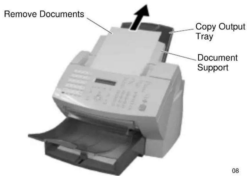
text_image
Remove Documents Copy Output Tray Document Support 082a. Bypass Tray
Pull up the Document Output Tray and pull the jammed paper straight out of the machine.

text_image
Document Output Tray Bypass TrayNote: When the jammed paper does not come out of the machine easily, try to remove the jammed paper from the inside of the machine. (See Step 8.)
Basic Troubleshooting
2b. Main Paper Tray
Remove the Bypass Tray and pull the jammed paper straight out of the machine.

text_image
Document Output Tray Bypass TrayNote: When the jammed paper does not come out of the machine easily, try to remove the jammed paper from the inside of the machine. (See Step 8.)
2c. Optional Paper Cassette
Remove the Optional Paper Cassette Cover and pull out Paper Cassette. Press down on the stack of paper until the paper lifting plate locks.
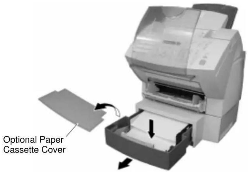
text_image
Optional Paper Cassette Cover11
Remove the stack of paper from the Optional Paper Cassette and pull the jammed paper straight out of the machine.
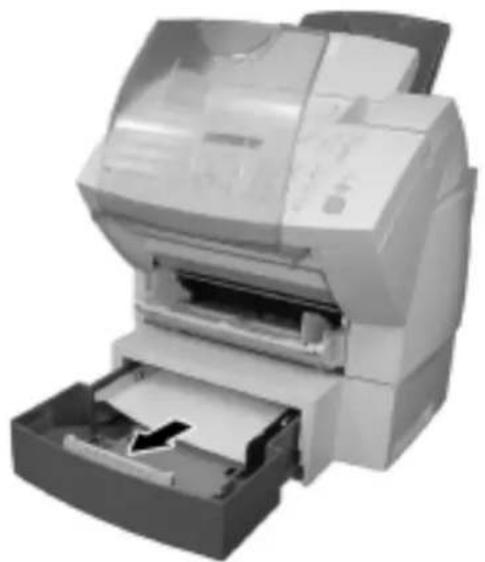
natural_image
Exterior view of a printer with paper feed and paper holder (no visible text or symbols)12
Basic Troubleshooting
- Push the Top Cover Open Button to the Top Cover and open the Top Cover.

text_image
Top Cover Open Button Top Cover 13- Remove the Toner Cartridge and the Drum Cartridge.
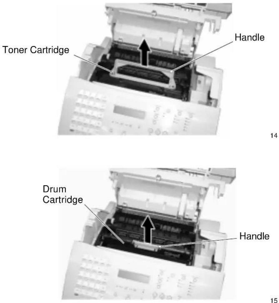
text_image
Toner Cartridge Handle 14 Drum Cartridge Handle 15Note: Immediately wrap the drum cartridge with a cloth to protect it against overexposure to light.
CAUTION
Always hold the Drum Cartridge and Toner Cartridge by the green handles. Do not expose the green drum to light for more than 3 minutes. Never expose it to direct sunlight or touch the green drum. Damage or poor print quality may result.
Basic Troubleshooting
- Pull up the Paper Guide and remove the jammed paper while pressing the Paper Holder to the rear side. Avoid tearing the paper.

text_image
Paper Guide Paper Holder 16
CAUTION
Do not touch the Image Transfer Roller.

WARNING
The black colored fuser housing may be hot if the machine was in use prior to this paper jam.
- If the paper is jammed partway through the Fuser Unit (black colored housing), remove the jammed paper in the direction of the arrow. Avoid tearing paper.
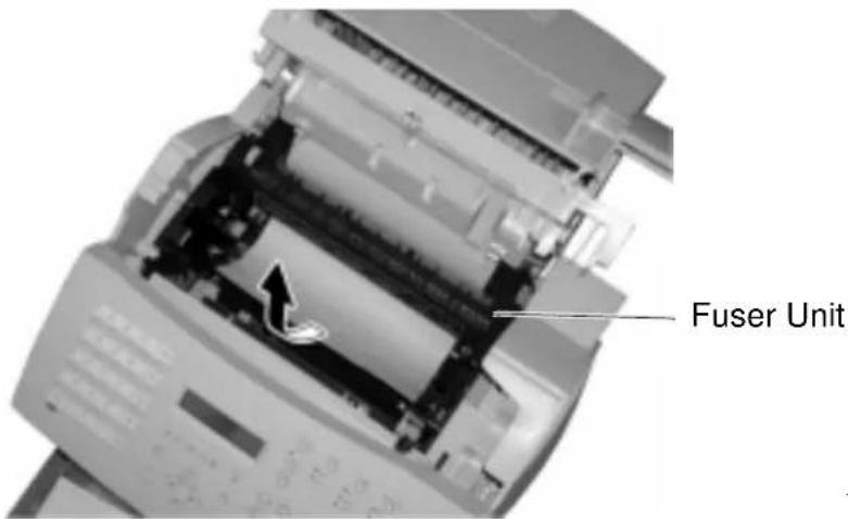
text_image
Fuser Unit4-8 WorkCentre Pro 555, 575
- If the paper is jammed partway through the Paper Exit Guide, open the Paper Exit Guide and remove the jammed paper.

text_image
Paper Exit Guide Hook18
- Install the drum cartridge into the machine, aligning the guides of the cartridge with the grooves inside the machine.
Color coordinated "1" labels have been affixed to the drum cartridge and to the inside of the machine. Install the drum cartridge by aligning these labels.
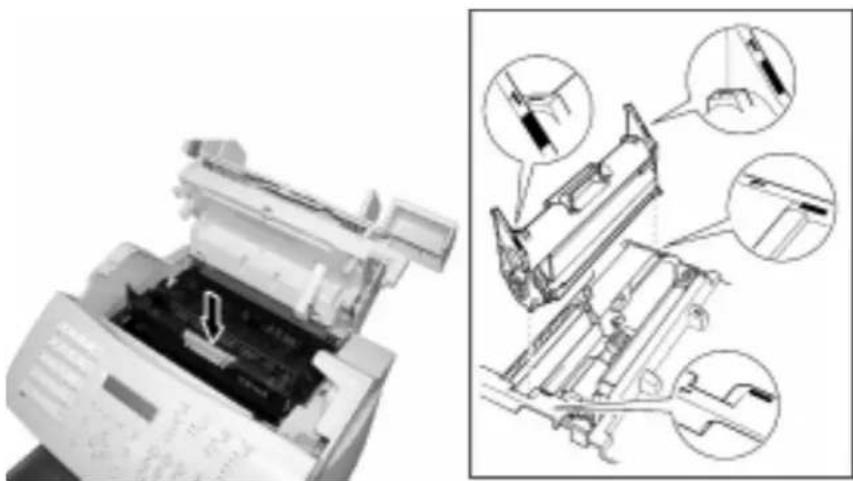
natural_image
Diagram showing a printer with internal components and a close-up of its internal structure, no text or symbols present.23
Make sure the drum cartridge is inserted inside the machine as far as it will go.
Basic Troubleshooting
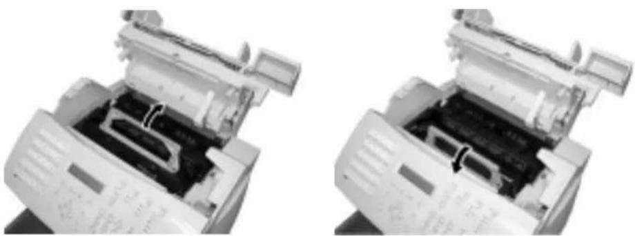
- Holding onto the toner cartridge's handle, lower it into the machine. Make sure that the four pins (two on each side) fit into the grooves inside the machine.
Color coordinated "2" labels have been affixed to the toner cartridge and to the inside of the machine. Install the toner cartridge by aligning these labels.

natural_image
Technical illustration of a printer with internal components and a separate mechanical assembly (no visible text or symbols)24
The cartridge will click into place when it is completely installed.
natural_image
Two views of a printer's internal structure, showing internal components and casing (no visible text or symbols)25 26
Basic Troubleshooting
-
Replace the Paper Exit Guide, Paper and Bypass Tray.
-
Press down on the Top Cover until a "Click" is heard to ensure the latches engage.
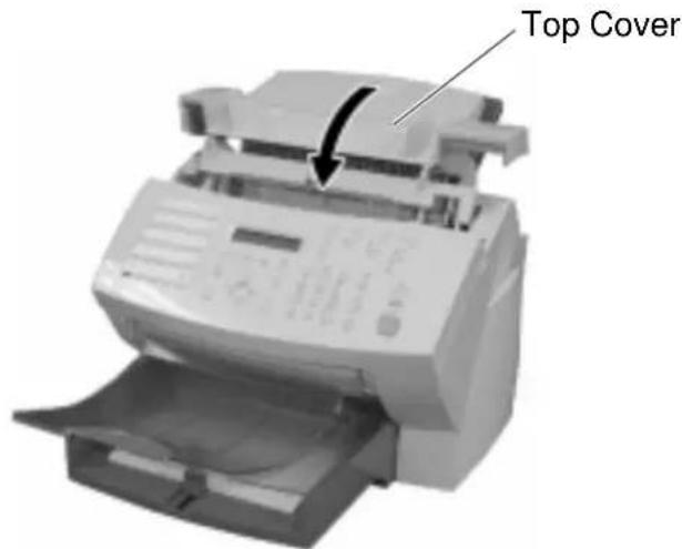
text_image
Top Cover19
- Verify the display has returned to the Standby Mode.
Document Jam
If a document jam occurs during a transmission, the message
"DOCUMENT JAM" is displayed. If this occurs, follow the procedure below.
It is recommended that a duplicate from a copier, of the jammed document be used to reduce the chance of a jam when resending the document.
See Chapter 3, "Loading Documents" for document specifications and recommendations which may help avoid paper jams.
Note: The power can be left ON when clearing a paper jam.
| Typical Causes of Document Jams | Recommended Procedure |
| The document is fed at an angle. | Adjust the Document Guides to the edges of the document. |
| The document paper is too thin or too thick. | Make a duplicate using a copier and use the copy as the sending document. |
| Document has tape or pieces of paper taped to it. | Remove the tape or make a duplicate using a copier and use the copy as the sending document. |
| The Control Panel Cover is not fully closed. | Close the Control Panel Cover fully. |
| The document is stapled. | Remove the staple(s), or make a duplicate using a copier and use the copy as the sending document. |
- Remove all documents from the Document Support.

text_image
Remove Documents Document Support Handle 08- Open the Control Panel Cover.
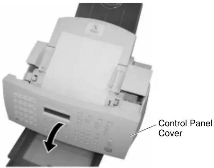
text_image
Control Panel CoverBasic Troubleshooting
- Remove the document jam. Remove any pieces of paper, paper clips, or staples that may have caused the jam.

text_image
Control Panel Cover21
- Close the Control Panel Cover.
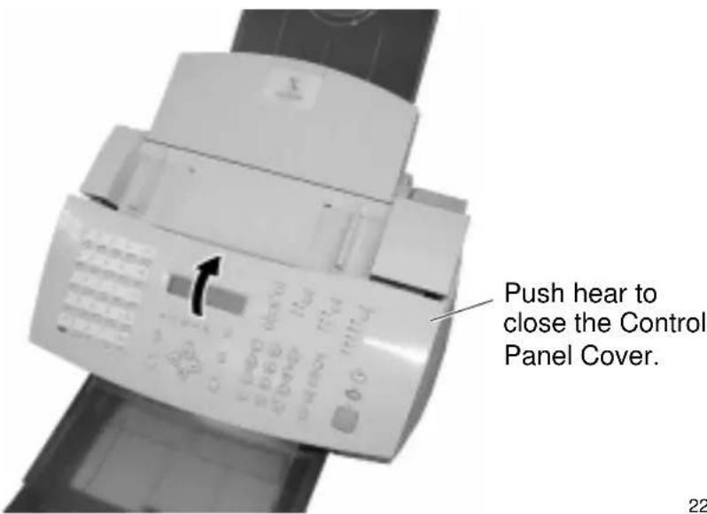
text_image
Push hear to close the Control Panel Cover.22
- Verify the display has returned to the Standby Mode.
A Safety Certification and Environmental Compliance
Your Xerox product and supplies have been designed and tested to meet strict safety requirements. These include safety agency examination and approval, and compliance to established environmental standards. Please read the following instructions carefully before operating the equipment and refer to them as needed to ensure the continued safe operation of your machine. The safety testing and performance of this product have been verified using Xerox materials only.
Follow all warnings and instructions marked on or supplied with the product.
$$ \begin{array}{l} \begin{array}{l} * \text {Symbology: = General warning alerts user to the risk of} \ \text {personal damage. Example of specific} \ \text {warning} \end{array} \ = \text { Warning Heated Surface } \ \end{array} $$
Unplug this equipment from the wall outlet before cleaning. Always use materials specifically designated for this product. Use of other materials may result in poor performance and could create a hazardous situation.
Do not use aerosol cleaners. Follow the instructions in this User Guide for proper cleaning methods.
Never use supplies or cleaning materials for purposes other than what they were intended. Keep all supplies and materials out of reach of children.
Do not use this product near water, wet locations, or outdoors.
Do not place this product on an unstable cart, stand or table. The product may fall, causing personal injury or serious damage to the copier

WARNING
This product must be earthed
This product is equipped with a 3-wire grounding type plug (e.g., a plug having a third grounding pin). This plug will fit only into a grounding-type power outlet. This is a safety feature. To avoid risk of electric shock, contact your electrician to replace the receptacle if you are unable to insert the plug into the outlet. Never us a grounding adapter plug to connect the copier to a power source receptacle that lacks a ground connection terminal.
This product should be operated from the type of power source indicated on the marking label. If you are not sure of the type of power available, consult your local power company.
Do not allow anything to rest on the power cord. Do not locate the product where persons will step on the cord.
Your equipment is equipped with an energy saving device to conserve power when the machine is not in use. The machine may be left on continuously.
Slots and Openings in the cabinet and in the back and sides of the product are provided for ventilation. To ensure reliable operation of the product and to protect it from overheating, these openings must not be blocked or covered. The product should never be located near or over a radiator or heat register. This product should not be placed in a built-in installation unless proper ventilation is provided.
Never push objects of any kind into the slots of the product as they may touch dangerous voltage points or short out parts which could result in a fire or electric shock.
Never spill liquid of any kind on the product.
Never remove covers or guards that require a tool for removal, unless directed to do so in a Xerox approved maintenance kit.
Never defeat interlock switches. Machines are designed to restrict operator access to unsafe areas. Covers, guards and interlock switches are provided to ensure that the machine will not operate with covers opened.
Use of an extension cord with this product is not recommended or authorized. Users should check building codes and insurance requirements if a properly earthed extension cord is to be used. Ensure that the total ampere ratings of the products plugged into the
extension cord do not exceed the extension cord ampere rating. Also, make sure that the total amperage of all products plugged into the wall outlets does not exceed the outlet rating.
Do not put your hands into the fuser area, located just inside the exit tray area, as you may be burned.
Ozone: This product produces ozone during normal operation. The ozone produced is dependent on copy volume and is heavier than air. Providing the correct environmental parameter, as specified in the Xerox installation procedures, ensure that concentration levels meet safe limits.
If you need additional safety information concerning the copier or Xerox supplied materials you may call the following number:
Europe: +44 (0)1707 353434
USA: 1800 928 6571
Laser Safety Information
This equipment is certified as a Class 1 laser product under the U.S. Department of Health and Human Services (DHHS) Radiation Performance Standard according to the Radiation Control for Health and Safety Act of 1968. This means that the facsimile does not produce hazardous laser radiation.
All laser light emitted inside the facsimile is completely confined within protective housings when any part of the facsimile is opened. This means that the facsimile is safe to use during normal operation and maintenance.

WARNING
Adjustment or performance of procedures other than those specified herein may result in hazardous laser exposure. Only trained and qualified personnel may open covers or remove parts that are not explicitly shown and described in the WorkCentre Pro 555/575 User's Guide as being accessible to the operator.
The Center for Devices and Radiological Health (CDRH) of the U.S. Food and Drug Administration implemented regulations for laser products in 1976. These regulations apply to laser products
manufactured from August 1, 1976. Compliance is mandatory for products marketed in the United States. The WorkCentre Pro is in compliance with the CDRH regulation.
The equipment also complies with laser product performance standards set by governmental, national and international agencies as a Class 1 Laser Product.
Third Party Certification
The Xerox WorkCentre Pro 555/575 is certified by various bodies in compliance with national and international safety standards.
120v 60Hz Nominal Markets:
Underwriter Laboratories Inc., UL 1950, Third Party Edition, within reciprocity agreements which include requirements for Canada.
230v, 50 Hz Nominal Markets:
IEC950: 1991 including A1, A2, A3 and A4.
The Xerox WorkCentre Pro 555/575 is manufactured under an ISO 9002 quality registration scheme.
Radio Frequency Emissions USA
This equipment has been tested and found to comply with the limits for a Class B digital device, pursuant to Part 15 of the FCC Rules. These limits are designed to provide reasonable protection against harmful interference in a residential installation. This equipment generates, uses, and can radiate radio frequency energy and, if not installed and used in accordance with the instructions, may cause harmful interference to radio communications. However, there is no guarantee that interference will not occur in a particular installation. If this equipment does cause harmful interference to radio or television reception, which can be determined by turning the equipment off an on, the user is encouraged to try to correct the interference by one or more of the following measures:
- Reorient or relocate the receiving antenna.
- Increase the separation between the equipment and the receiver.
- Connect the equipment into an outlet on a circuit different from that to which the receiver is connected.
- Consult the dealer or an experienced radio/TV technician for help.
Changes or modifications to this equipment not specifically approved by the Xerox Corporation may void the users authority to operate this equipment.
WARNING
Shielded cables must be used with this equipment to maintain compliance with FCC regulations
Approvals and Certification
CE
The CE marking applied to this product symbolizes Xerox Limited Declaration of Conformity with the following applicable Directives of the European Union as of the dates indicated:
January 1, 1995: Council Directive 73/23/EEC amended by Council Directive 93/68/EEC, approximation of the laws of the member states related to low voltage equipment.
January 1, 1996: Council Directive 89/336/EEC, approximation of the laws of the member states related to electromagnetic compatibility.
March 9, 1999: Council Directive 99/5/EEC approximation of the laws of the member states related to R&TTE.
A full declaration, defining the relevant directives and referenced standards can be obtained from your Xerox Limited representative or by contacting:
Xerox Limited Environmental Health and Safety,
Xerox Limited Technical Centre,
PO Box 17,
Bessemer Road,
Welwyn Garden City,
Herts AL7 1HE, England
Telephone: +44(0)1707 353434
WARNING
This product is certified manufactured and tested in compliance with strict safety and radio frequency interference regulations. Any unauthorized alteration which includes the addition of new functions or the connection of external devices may impact this certification. Please contact your local Xerox Limited representative for a list of approved accessories.
WARNING
In order to allow this product to operate in proximity to industrial, Scientific and medical (ISM) equipment, the external radiation from the ISM equipment may have to be limited or special mitigation measures taken.
WARNING
Shielded cables must be used with this equipment to maintain compliance with Council Directive 89/336/EEC.
UK Electricity at Work Regulation
The Electricity at Work Regulation 1989 came into force in England and Wales on the 1 April 1990. This 1989 Regulation places a duty on all employers and self-employed persons to ensure the electrical system in their premises are constructed, maintained and operated in such a manner as to prevent, so far as reasonably practical, danger. This includes ensuring all electrical equipment connected to such electrical systems are safely constructed, maintained and operated.
All Xerox equipment have been designed to exacting safety standards. They have all undergone a variety of stringent safety tests including earth bond, insulation resistance and electrical strength tests. Xerox Limited manufacturing plants have been awarded ISO 9000 quality certification and are subject to regular audits by the British Standards Institution or equivalent national standards body.
Xerox equipment which has been properly and regularly serviced and maintained should not have to undergo additional specific safety tests pursuant to the 1989 Regulation. Customers wishing to complete safety testing should contact Xerox Limited Technical Centre (see page 1) for advice prior to any test implementation.
Xerox equipment should, however, be properly and regularly serviced and maintained at all times.
QUESTION: What is the Electricity at Work Regulation?
ANSWER: The Electricity at Work Regulation 1989 came into force in England and Wales on the 1 April 1990. This 1989 Regulation places a duty on all employers and self-employed persons to ensure the electrical systems in their premises are constructed, maintained and operated in such a manner as to prevent, so far as reasonably
practicable, danger. This includes ensuring all electrical products connected to such electrical systems are safely constructed, maintained and operated.
QUESTION: Does Xerox Limited comply with the Electricity at Work Regulation?
ANSWER: The regulation places a duty on all employers and self-employed persons to ensure the electrical systems in their premises are, effectively safe.
The regulation does not impose on, amongst others, manufacturers or suppliers of such electrical systems. However, rest assured that all Xerox equipment which Xerox Limited and its authorized distributors supplies to customers, conform with all the relevant safety legislation and standards.
QUESTION: Is Xerox equipment safe?
ANSWER: All Xerox equipment supplied by Xerox Limited and their authorized distributors conform to all relevant safety legislation and standards.
QUESTION: Is the Xerox equipment in my premises safe?
ANSWER: All Xerox equipment supplied by Xerox Limited and their authorized distributors conform to all relevant safety legislation and standards. However, like all electrical equipment, they have to be regularly serviced and maintained by competent persons.
Xerox Limited Customer Service Engineers ensure Xerox equipment is serviced and maintained to exacting Xerox safety standards. If you would like your Xerox equipment to be serviced and maintained to such high standards, please contact your local Xerox Limited Customer Service Organization. They will be pleased to assist you.
QUESTION: Does the Xerox equipment in my premises comply with the Electricity at Work Regulations?
ANSWER: All employers and self-employed persons must ensure that the electrical systems in their premises are safe. This will include ensuring Xerox equipment in such premises is safe.
Xerox Limited's Product Safety function has prepared a guide which contains a list of tests which may be completed by your Xerox Limited Customer Service Organization. THESE TESTS MUST BE CARRIED OUT ONLY BY PERSONS WHO POSSESS THE RELEVANT SKILL, KNOWLEDGE AND EXPERIENCE TO CARRY OUT SUCH TESTS.
Please contact the Xerox Limited Customer Service Organization for further information.
THE USE OF INAPPROPRIATE TEST PROCEDURES AND TEST EQUIPMENT MAY PROVIDE MISLEADING RESULTS AND MAY CAUSE DEATH, PERSONAL INJURY AND/OR DAMAGE TO PROPERTY.
QUESTION: I would like to carry out my own safety tests on the Xerox equipment in my premises.
ANSWER: You may, of course, request such tests as you deem necessary to satisfy yourself that your Xerox equipment is safe. Your Xerox Limited Customer Support will be pleased to advise you on such testing.
QUESTION: I require records of all tests
ANSWER: After safety testing, your Xerox Limited Customer Service Engineer will provide you with a certificate which details the results of all tests completed.
In the event of any defect being noted, the Xerox equipment will be switched off and disconnected from the supply until the defect has been corrected. You will be advised of such action to enable such defects to be corrected.
PLEASE NOTE: YOU MUST ENSURE THAT YOUR XEROX EQUIPMENT IS SAFE AT ALL TIMES
Please contact us if you have any queries regarding the information provided in this document.
Xerox Limited Environmental Health and Safety,
Xerox Limited Technical Centre,
PO Box 17,
Bessemer Road,
Welwyn Garden City,
Herts AL7 1HE, England
ENERGY STAR®
Xerox Corporation designed this product to comply with the guidelines of the ENERGY STAR program of the Environmental Protection Agency. As an ENERGY STAR Partner, Xerox has determined that this copier model meets the ENERGY STAR guidelines for energy efficiency.
Low Power and Sleep Mode
The Workcentre Pro 555/575 switch to a standby mode of operation when each task has been completed.
In this mode of operation the power consumption is less than the 'Sleep Mode' energy efficiency limit required to satisfy energy start requirements.
The machine recovers from standby mode when any task is initiated within 20 seconds.

text_image
energyEnvironmental Choice ^M
120v, 60Hz products for Canada.
Terra Choice Environmental Services Inc, of Canada has verified that this Xerox product conforms to all applicable Environmental Choice EcoLogo requirements for minimized impact on the environment.
SWISS ENERGY 2000
Xerox Corporation has designed and tested this product to meet the energy restrictions required by Swiss Energy 2000 compliance has been notified to the registration authorities.
Recycled Paper
The WorkCentre Pro 555/575 has established performance with the use of recycled paper with its consequent benefits to the environment. Xerox recommends part numbers:
3R94565, A4 stock, 80g/m ^2 500 sheets
3R6296, 8.5 x 11 inch stock, 80 g/m ^4 500 sheets
The paper contains 50% post consumer content and can be obtained through Xerox and many other office suppliers.
European Fax Approvals and Certification
This Xerox product has been self-certified by Xerox for pan-European single terminal connection to the analogue public switched telephone network (PSTN) in accordance with Directive 1999/5/EC.
The product has been designed to work with the national PSTNs and compatible PBXs of the following countries:
Austria Germany Luxembourg Sweden
Belgium Greece Netherlands Switzerland
Denmark Iceland Norway United Kingdom
France Ireland Portugal
Finland Italy Spain
In the event of problems, you should contact your local Xerox representative in the first instance.
The product has been tested against TBR21. To assist in the use and application of terminal equipment which complies with this standard, the European Telecommunication Standards Institute (ETSI) has issued an advisory document (EG 201 121) which contains notes and additional requirements to ensure network compatibility of TBR21 terminals. The product has been designed against, and is fully compliant with, all of the relevant advisory notes contained in this document.
The product may be configured to be compatible with other country networks. Please contact your Xerox representative if it needs to be reconnected to another country's network. There are no user-adjustable settings in the product.
NOTE: Although this product can use either loop disconnect (pulse) or DTMF (tone) signalling it is recommended that it is set to use DTMF signalling. DTMF signalling provides reliable and faster call set-up.
Modification, connection to external control software or to external control apparatus not authorised by Xerox, will invalidate its certification.
Send Header Requirements
Federal Communications Commission (FCC) regulations require all persons within the United States who send any message via a facsimile machine to include an identifying message in the transmission. The message must clearly contain an identifier and telephone number for the entity (business or individual) sending the message.
This facsimile machine provides the local ID and name features required for the FCC regulation. To satisfy the FCC regulation, the telephone number and name must be included with the printed document. To comply with the FCC rules, carefully read and follow the instructions listed in this document to program the local ID and name.
Data Coupler Information
This Xerox WorkCentre Pro 555/575 machine contains an internal data coupler. Its use is restricted by the FCC (Federal Communications Commission). To comply with the FCC rules, you must carefully read and follow the instructions listed below.
This equipment complies with Part 68 of the FCC rules. On the rear of this equipment is a label that contains, among other information, the FCC registration number and Ringer Equivalence Number (REN). If requested, provide this information to your telephone company.
The REN is useful to determine the quantity of devices you may connect to your telephone line and still have all of those devices ring when your number is called. In most, but not all areas, the sum of the RENs of all devices should not exceed five (5.0). To be certain of the number of devices you may connect to your line, as determined by the REN, you should call your local telephone company to determine the maximum REN for your calling area.
WARNING
Ask your local telephone company for the modular jack type installed on your line. Connecting this machine to an unauthorized jack can severely damage telephone company equipment. You, not Xerox, assume all responsibility and/or liability for any damage caused by the connection of this machine to an unauthorized jack.
You may safely connect the machine to the following standard modular jack: USOC RJ-11C. Use the standard line cord (with modular plugs) provided with the installation kit to connect it.
An FCC compliant telephone cord and modular plug is provided with this equipment. This equipment is designed to be connected to the telephone network or premises wiring using a compatible modular jack which is Part 68 compliant.
Do not connect this machine to a party or coin operated phone line.
Repairs to the machine should be made only by a Xerox representative or an authorized Xerox service agency. This applies at any time during or after the service warranty period. If unauthorized repair is performed, the remainder of the warranty period is null and void.
If you find the telephone line is damaged or the telephone company notifies you that your machine is causing damage, disconnect the machine from the telephone line and call for service. Do not reconnect the machine until necessary repairs are made.
The telephone company will, where practical, notify you when they need to temporarily disconnect service. However, if action is reasonable and necessary, but prior notice is not practical, they may still temporarily disconnect your service. In such cases they must:
Immediately notify you of their temporary action.
Reconnect service when the source of damage is removed.
Inform you of your rights to bring a complaint to the FCC under FCC rules.
The telephone company may make changes to its communications facilities, equipment, operations, or procedures. Such action must be reasonable, required in the operation of their business, and consistent with FCC rules. They must give you prior written notification if the changes can:
Make your machine incompatible with their equipment.
Require modification or alteration of the machine.
Otherwise physically affect performance of the machine.
WARNING
When programming emergency numbers and/or making test calls to emergency numbers:
Remain on the line and briefly explain to the dispatcher the reason for the call before hanging up.
Perform such activities in the off-peak hours, such as early morning hours or late evenings.
Canadian Certification
Notice: The Industry Canada Label on the machine identifies certified equipment. This certification means that the equipment meets certain telecommunications networks protective, operational and safety requirements. Industry Canada does not guarantee the equipment will operate to the user's satisfaction.
Before installing this equipment, users should ensure that it is permissible to be connected to the facilities of the local telecommunications company. The equipment must also be installed using an acceptable method of connection. In some cases, the company's inside wiring associated with a single line individual service may be extended by means of a certified connector assembly (telephone extension cord).
The customer should be aware that compliance with the above conditions may not prevent degradation of service in some situations.
Repairs to certified equipment should be made by an authorized Canadian maintenance facility designated by the supplier. Any repairs or alterations made by the user to this equipment, or equipment malfunctions, may give the telecommunications company cause to request the user to disconnect the equipment.
Users should ensure for their own protection the electrical ground connections of the power utility, telephone lines and internal metallic water pipe system, if present, are connected together. This precaution may be particularly important in rural areas.

CAUTION
Users should not attempt to make such connections themselves, but should contact the appropriate electric inspection authority or electrician, as appropriate.
Notice: The Ringer Equivalence Number (REN) assigned to each terminal device provides an indication of the maximum number of terminals allowed to be connected to a telephone interface. The termination on an interface may consist of any combination of devices subject only to the requirement that the sum of the Ringer Equivalence Numbers of all the devices does not exceed 5.
This digital apparatus does not exceed the Class A limits for radio noise emissions from digital apparatus set out in the Radio Interference Regulations of Industry Canada.
Activity Key described 2-13
ADF see also document feeder document size 3-17 document specifications 3-17 loading documents 3-17–3-20
alarms lights, described 2-10
alpha dialing key 2-10
alphabet Alphabet Phonebook 3-26 phonebook 3-26
Alphabet Phonebook 3-26 automatic document feeder see also document feeder document size 3-17 document specifications 3-17 loading documents 3-17–3-20
avoiding document jams 4-12
B
batching described 2-3
battery 2-1
C
calendar setting the date and time 3-3
Cancel Job Key described 2-11
cassette
WorkCentre Pro 555/575 INDEX-1
see paper tray causes of document jams 4-12
Charge Code Key described 2-13
clearing document jams 4-12 paper jams 4-1
communication lights described 2-9
communication mode 2-15
communications communication lights 2-9 communication modes 2-15 group dialing, described 2-2
components control panel, listed 2-9
confirmation tone 2-14
consumables paper 3-11
contrast see also resolution changing 3-20
Contrast Key described 2-11
control panel 2-8–2-13 components, listed 2-9 described 2-4 direct access function keys, described 2-13 document jams 4-12 function keys, described 2-9–2-13 illustrated 2-8
Copy Key described 2-11
copy mode 2-16 copying 3-21
preventing document jams 4-12
D
darken contrast 3-20
date setting 3-3
Delete Key described 2-9
dial directory see also one touch phonebook
dial mode setting 3-8
Direct Access Function Keys described 2-13
Direct Send Key described 2-13
disabling receive footer 3-10 send header 3-9
display see also LCD
document feeder document specifications 3-17
document guides described 2-4
document jams 4-12 causes 4-12 clearing 4-12 paper types to avoid 3-17
document out tray described 2-4
document size 3-17
document tray loading documents 3-17 maximum documents 3-17
documents document jams 4-12 loading 3-17–3-20 specifications 3-17 types to avoid 3-17
Down Arrow Key described 2-9
INDEX-2 WorkCentre Pro 555/575
E
enabling receive footer 3-10 send header 3-9
enriched system functions described 2-2
Enter Key described 2-10
environmental compliance A-1–A-16 ENERGY STAR A-10 Environmental Choice A-10 SWISS ENERGY 2000 A-11
extended tone 2-14
F
fax communications see receiving documents, retrieving documents, transmitting
fax headers setting 3-9
features hardware features, listed 2-4 system features, listed 2-2-2-3
fine resolution 3-19
footer enabling 3-10
function keys described 2-9–2-13
G
group dialing described 2-2 group phonebook 3-25 Manual Group Key 2-11
Group Phonebook 3-25
H
halftone see photo, resolution
hardware features listed 2-4
header
enabling 3-9
|
ID
setting the machine ID 3-6
idle mode 2-1
see also standby mode
Insert Key
described 2-10
installation instructions
space requirements 2-7
system requirements 2-6
J
Job Status Key
described 2-12
junk mail
described 2-3
K
keys
direct access function keys 2-13
function keys 2-9-2-13
L
language
setting 3-2
laser safety A-3
LCD
communication mode 2-15
described 2-9
menu mode 2-16
standby mode 2-15
LEDs
alarm lights, described 2-10
communications lights, described 2-9
Left Arrow Key
described 2-9
lighten contrast 3-20
lists
see also reports
group numbers 3-25
WorkCentre Pro 555/575 INDEX-3
phonebook reports 3-22–3-25
loading documents 3-17–3-20
M
machine
hardware features 2-4–2-5
overview 2-1
system features 2-2-2-3
tones 2-14
machine ID
setting 3-6
machine language
setting 3-2
refuse junk mail, described 2-3
mailbox communications
described 2-2
maintaining the machine
paper, replacing 3-11
Manual Dial Key
described 2-11
Manual Group Key
described 2-11
maximum document size 3-17
memory
paper jams 4-1
Menu Key
described 2-9
menu mode 2-1, 2-16
menus
see also menu mode
minimum document size 3-17
modes of operation 2-15–2-16
communication modes 2-15
copy mode 2-16
menu mode 2-16
PC printing mode 2-16
standby mode 2-15
multi access
described 2-2
N
normal contrast 3-20
Numeric Keypad described 2-10
0
one touch dialing see also one touch keys described 2-2 One Touch Phonebook 3-24
one touch keys see also speed dialing described 2-12
One Touch Phonebook 3-24
operation modes 2-15–2-16 communication mode 2-15 copy mode 2-16 menu mode 2-16 standby mode 2-15
operator control panel 2-8–2-13 see also control panel output tray document out tray, described 2-4
P
page numbers receive footer 3-10 send header 3-9
paper document specifications 3-17 paper jams 4-1–4-11 replacing 3-11
paper jams 4-1-4-11
paper quality avoiding document jams 4-12
paper tray replacing paper 3-13
Pause Key 2-10
PC printing mode 2-16
Phonebook Key described 2-13 used 3-22
phonebook reports 3-22–3-25 alphabet 3-26 group 3-25 one touch 3-24 speed dial 3-23
Photo 3-19 power saver mode described 2-3 print darkness setting the contrast 3-20 printing from a PC 2-1 phonebook reports 3-22–3-25
programming date and time 3-3 dial mode 3-8 language 3-2 machine ID 3-6
pulse dial mode 3-8 see also dial mode
Q
quick start 3-21
R
receive footer enabling 3-10 receiving documents 3 paper jams 4-1
recording on plain paper 2-2 Redial/Pause Key described 2-10
refuse junk mail described 2-3
reports Alphabet Phonebook 3-26 Group Phonebook 3-25 One Touch Phonebook 3-24 Speed Dial Phonebook 3-23
requirements space 2-7
system 2-6
resolution
see also contrast
changing 3-19
high resolution, described 2-2
for scanning 3-19
selections 3-19
Resolution Key
described 2-11
selecting the scan resolution 3-19
Right Arrow Key
described 2-9
S
safety certification A-1-A-16
Canada A-15
CE marking A-6
European certification A-6
fax approvals A-12
FCC regulations A-13
safety requirements
ampere ratings A-2
building codes A-2
cleaning A-1
covers A-2
data coupler A-13
earthing A-2
energy saving A-2
extension cord A-2
fuser area A-3
grounding A-2
guards A-2
insurance requirements A-2
interlock switches A-2
laser safety A-3
location A-2
ozone A-3
power source A-2
radio frequency emissions A-4
send header A-13
telecommunications requirements
A-12-A-16
UK electricity at work regulation A-7
ventilation A-2
warnings A-1
scan resolution
changing 3-19
scanning
setting the contrast 3-20
setting the resolution 3-19
send header
enabling 3-9
sending documents 3-21
sequential transmissions
see batching
setting
contrast 3-20
date and time 3-3
dial mode 3-8
language 3-2
machine ID 3-6
receive footer 3-10
resolution 3-19
send header 3-9
single tone 2-14
space requirements 2-7
specifications
documents 3-17
speed dial keys
see speed dial numbers
speed dial numbers
phonebook 3-23
Speed Dial Phonebook 3-23
Speed Dial/Alpha/Group Key
described 2-10
speed dialing
described 2-2
Speed Dial Phonebook 3-23
standard resolution 3-19
standby mode 2-1, 2-15
Start Key
described 2-10
Stop Key
described 2-10
super fine resolution 3-19
system features
listed 2-2-2-3
requirements 2-6
system menu
system password 3-6
T
time
setting 3-3
tone dial mode 3-8
tones 2-14
tray
described 2-4
troubleshooting 4-1–4-14
document jams 4-12
paper jams 4-1–4-11
W
WorkCentre Pro 745
hardware features 2-4
overview 2-1
system features 2-2-2-3
tones 2-14