X11SCA-W - Motherboard Supermicro - Free user manual and instructions
Find the device manual for free X11SCA-W Supermicro in PDF.

User questions about X11SCA-W Supermicro
0 question about this device. Answer the ones you know or ask your own.
Ask a new question about this device
Download the instructions for your Motherboard in PDF format for free! Find your manual X11SCA-W - Supermicro and take your electronic device back in hand. On this page are published all the documents necessary for the use of your device. X11SCA-W by Supermicro.
USER MANUAL X11SCA-W Supermicro
The information in this user's manual has been carefully reviewed and is believed to be accurate. The vendor assumes no responsibility for any inaccuracies that may be contained in this document, and makes no commitment to update or to keep current the information in this manual, or to notify any person or organization of the updates. Please Note: For the most up-to-date version of this manual, please see our website at www.supermicro.com.
Super Micro Computer, Inc. ("Supermicro") reserves the right to make changes to the product described in this manual at any time and without notice. This product, including software and documentation, is the property of Supermicro and/or its licensors, and is supplied only under a license. Any use or reproduction of this product is not allowed, except as expressly permitted by the terms of said license.
IN NO EVENT WILL Super Micro Computer, Inc. BE LIABLE FOR DIRECT, INDIRECT, SPECIAL, INCIDENTAL, SPECULATIVE OR CONSEQUENTIAL DAMAGES ARISING FROM THE USE OR INABILITY TO USE THIS PRODUCT OR DOCUMENTATION, EVEN IF ADVISED OF THE POSSIBILITY OF SUCH DAMAGES. IN PARTICULAR, SUPER MICRO COMPUTER, INC. SHALL NOT HAVE LIABILITY FOR ANY HARDWARE, SOFTWARE, OR DATA STORED OR USED WITH THE PRODUCT, INCLUDING THE COSTS OF REPAIRING, REPLACING, INTEGRATING, INSTALLING OR RECOVERING SUCH HARDWARE, SOFTWARE, OR DATA.
Any disputes arising between manufacturer and customer shall be governed by the laws of Santa Clara County in the State of California, USA. The State of California, County of Santa Clara shall be the exclusive venue for the resolution of any such disputes. Supermicro's total liability for all claims will not exceed the price paid for the hardware product.
FCC Statement: This equipment has been tested and found to comply with the limits for a Class B digital device pursuant to Part 15 of the FCC Rules. These limits are designed to provide reasonable protection against harmful interference when the equipment is operated in a consumer environment or residential installation. This equipment generates, uses, and can radiate radio frequency energy and, if not installed and used in accordance with the manufacturer's instruction manual, may cause harmful interference with radio communications. Operation of this equipment in a residential area is likely to cause harmful interference, in which case you will be required to correct the interference at your own expense.
California Best Management Practices Regulations for Perchlorate Materials: This Perchlorate warning applies only to products containing CR (Manganese Dioxide) Lithium coin cells. "Perchlorate Material-special handling may apply. See www.dtsc.ca.gov/hazardouswaste/perchlorate".

WARNING: This product can expose you to chemicals including lead, known to the State of California to cause cancer and birth defects or other reproductive harm. For more information, go to www.P65Warnings.ca.gov.
The products sold by Supermicro are not intended for and will not be used in life support systems, medical equipment, nuclear facilities or systems, aircraft, aircraft devices, aircraft/emergency communication devices or other critical systems whose failure to perform be reasonably expected to result in significant injury or loss of life or catastrophic property damage. Accordingly, Supermicro disclaims any and all liability, and should buyer use or sell such products for use in such ultra-hazardous applications, it does so entirely at its own risk. Furthermore, buyer agrees to fully indemnify, defend and hold Supermicro harmless for and against any and all claims, demands, actions, litigation, and proceedings of any kind arising out of or related to such ultra-hazardous use or sale.
Manual Revision: 1.2
Release Date: January 13, 2022
Unless you request and receive written permission from Super Micro Computer, Inc., you may not copy any part of this document. Information in this document is subject to change without notice. Other products and companies referred to herein are trademarks or registered trademarks of their respective companies or mark holders.
Copyright © 2022 by Super Micro Computer, Inc.
All rights reserved.
Printed in the United States of America
Preface
About This Manual
This manual is written for system integrators, IT technicians, and knowledgeable end users. It provides information for the installation and use of the X11SCA/-W/-F motherboard.
About This Motherboard
The X11SCA/-W/-F motherboard supports a single Intel® Xeon® E, Core™ i3/i5/i7/i9, Pentium®, and Celeron® series processor in an LGA 1151 (H4) socket. With the Intel C246 chipset, this motherboard supports DDR4 2666 MHz memory, SATA 3.0 ports, PCIe 3.0 slots, M.2 slots, 1G LAN ports, and IPMI. This motherboard offers a cost-effective WIO server solution and is ideal for 1U/2 AOC applications. Please note that this motherboard is intended to be installed and serviced by professional technicians only. For processor/memory updates, please refer to our website at http://www.supermicro.com/products/.
Conventions Used in the Manual
Special attention should be given to the following symbols for proper installation and to prevent damage done to the components or injury to yourself:

Warning! Indicates important information given to prevent equipment/property damage or personal injury.

Warning! Indicates high voltage may be encountered when performing a procedure.

Important: Important information given to ensure proper system installation or to relay safety precautions.

Note: Additional Information given to differentiate various models or to provide information for correct system setup.
Contacting Supermicro
Headquarters
Address: Super Micro Computer, Inc.
980 Rock Ave.
San Jose, CA 95131 U.S.A.
Tel: +1 (408) 503-8000
Fax: +1 (408) 503-8008
Email: marketing@supermicro.com (General Information)
support@supermicro.com (Technical Support)
Website: www.supermicro.com
Europe
Address: Super Micro Computer B.V.
's-Hertogenbosch, The Netherlands
Tel: +31 (0) 73-6400390
Fax: +31 (0) 73-6416525
Email: sales@supermicro.nl (General Information)
support@supermicro.nl (Technical Support)
rma@supermicro.nl (Customer Support)
Website: www.supermicro.nl
Asia-Pacific
Address: Super Micro Computer, Inc.
3F, No. 150, Jian 1st Rd.
Zhonghe Dist., New Taipei City 235
Taiwan (R.O.C)
Tel: +886-(2) 8226-3990
Fax: +886-(2) 8226-3992
Email: support@supermicro.com.tw
Website: www.supermicro.com.tw
Table of Contents
Chapter 1 Introduction
1.1 Checklist (For Single Color Box Packing only)....8
Quick Reference 15
Quick Reference Table....16
Motherboard Features....18
1.2 Processor and Chipset Overview....22
1.3 Special Features ....22
Recovery from AC Power Loss....22
1.4 System Health Monitoring....23
Onboard Voltage Monitors (X11SCA-F only)....23
Fan Status Monitor with Firmware Control 23
Environmental Temperature Control (X11SCA-F only) 23
System Resource Alert....23
1.5 ACPI Features....23
1.6 Power Supply 24
1.7 Serial Port....24
Chapter 2 Installation
2.1 Static-Sensitive Devices....25
Precautions 25
Unpacking 25
2.2 Motherboard Installation....26
Tools Needed ....26
Location of Mounting Holes 26
Installing the Motherboard....27
2.3 Processor and Heatsink Installation....28
Installing the LGA1151 Processor....28
Installing an Active CPU Heatsink with Fan 31
Removing a Heatsink....33
2.4 Memory Support and Installation ....34
Memory Support....34
Installing DDR4 Memory 34
Removing Memory Modules ....34
DIMM Module Population Sequence 35
2.5 M.2 Installation (optional)....36
2.6 Rear I/O Ports ....37
2.7 Front Control Panel 41
2.8 Connectors 46
Power Connections 46
Headers....48
2.9 Jumper Settings ....55
How Jumpers Work....55
2.10 LED Indicators....59
Chapter 3 Troubleshooting
3.1 Troubleshooting Procedures ......62
Before Power On 62
No Power 62
No Video 62
System Boot Failure....63
Memory Errors 63
Losing the System's Setup Configuration....64
When the System Becomes Unstable....64
3.2 Technical Support Procedures ......66
3.3 Frequently Asked Questions....67
3.4 Battery Removal and Installation 68
Battery Removal....68
Proper Battery Disposal....68
Battery Installation....68
3.5 Returning Merchandise for Service....69
Chapter 4 UEFI BIOS
4.1 Introduction....70
Starting the Setup Utility 70
4.2 Main....71
4.3 Advanced....72
4.4 Event Logs ....104
4.5 Thermal & Fan (Available on X11SCA-W)....106
4.6 IPMI (Available on X11SCA-F) 108
4.7 Security....111
4.8 Boot....117
4.9 Save & Exit....119
Appendix A BIOS Codes
Appendix B Software
B.1 Microsoft Windows OS Installation....122
B.2 Driver Installation....124
B.3 SuperDoctor ^® 5....125
B.4 IPMI (X11SCA-F only)....126
B.5 Logging into the BMC (Baseboard Management Controller) (X11SCA-F only) .....126
Appendix C Standardized Warning Statements
Battery Handling....127
Product Disposal 129
Appendix D UEFI BIOS Recovery
D.1 Overview....130
D.2 Recovering the UEFI BIOS Image....130
D.3 Recovering the BIOS Block with a USB Device....130
Chapter 1
Introduction
Congratulations on purchasing your computer motherboard from an industry leader. Supermicro motherboards are designed to provide you with the highest standards in quality and performance.
Several important parts that are included with the motherboard are listed below. If anything listed is damaged or missing, please contact your retailer.
1.1 Checklist(For Single Color Box Packing only)
| Main Parts List | ||
| Description Part Number Quantity | ||
| Supermicro Motherboard X11SCA/-W/-F 1 | ||
| SATA Cables CBL-0044L 6 | ||
| Quick Reference Guide MNL-2087-QRG 1 | ||
| IO Shield MCP-260-00122-0N 1 | ||
| M.2 Holder MCP-450-00005-0B 1 | ||
| Antenna (X11SCA-W only) | CBL-ANTDB-SMA | 2 |
Important Links
For your system to work properly, please follow the links below to download all necessary drivers/utilities and the user's manual for your server.
• Supermicro product manuals: http://www.supermicro.com/support/manuals/
- Product drivers and utilities: https://www.supermicro.com/wftp/driver/
- Product safety info: http://www.supermicro.com/about/policies/safety_information.cfm
- A secure data deletion tool designed to fully erase all data from storage devices can be found at our website: https://www.supermicro.com/about/policies/disclaimer.cfm?url=/wftp/utility/Lot9_Secure_Data_Deletion_Utility/
- If you have any questions, please contact our support team at: support@supermicro.com
This manual may be periodically updated without notice. Please check the Supermicro website for possible updates to the manual revision level.
Figure 1-1. X11SCA Motherboard Image
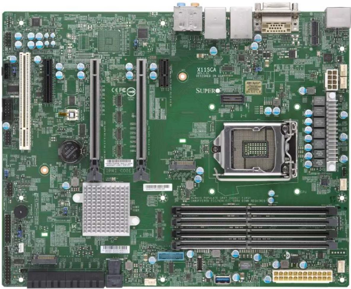
natural_image
Green printed circuit board with various components and connectors (no readable text or symbols)
Note: All graphics shown in this manual were based upon the latest PCB revision available at the time of publication of the manual. The motherboard you received may or may not look exactly the same as the graphics shown in this manual.
Figure 1-2. X11SCA-W Motherboard Image
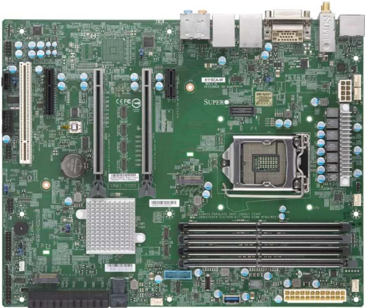
natural_image
Green computer motherboard with various electronic components and connectors (no readable text or symbols)Note: All graphics shown in this manual were based upon the latest PCB revision available at the time of publication of the manual. The motherboard you received may or may not look exactly the same as the graphics shown in this manual.
Figure 1-2. X11SCA-F Motherboard Image

natural_image
Green computer motherboard with various electronic components and connectors (no readable text or symbols)Note: All graphics shown in this manual were based upon the latest PCB revision available at the time of publication of the manual. The motherboard you received may or may not look exactly the same as the graphics shown in this manual.
Figure 1-3. X11SCA Motherboard Layout

text_image
AUDIO FP JPL2 AUDIO LAN2 USB2/3(3.0) LAN1 USB6/7(3.1) DVI DP HDMI X11 SCA REV.1.00 DESIGNED IN USA JPL1 SUSER JPYW2 CPU_FAN2 SYS_FAN3 JVR1 CPU_FAN1 ALISA POPULATE GRAI SOCKET FIRST UNB ECC/HON-ECC DRF4 DIMM REQUIFED DIMMA1 DIMMA2 DIMMB1 DIMMB2 JPI2CT JPYW1 SYS_FAN1 JPLC1 PCI Slot7 PCIE 3.0 X4 PCI Slot7 PCIE 3.0 X8 (IN X16) CPU Slot4 PCIE 3.0 X8 (IN X16) CPU Slot6 PCIE 3.0 X16 PCI Slot7 PCIE 3.0 X1 B3 BAR CODE IPWI CODE JWD1 LED_PDS_S6 JPNK2 JST1 CMOS CLEAR JSPR JSD1 PCI E M.2 M1 MAC CODE I-SATA4 I-SATA2 I-SATA0 I-SATA5 I-SATA3 I-SATA1 U2-1 USB4/5 (3.0) USB8 (3.1,TypeC) USB9 (3.1,TypeA) JSD1 (5.0) JSD1 (5.0) JSD1 (5.0) JSD1 (5.0) JSD1 (5.0) JSD1 (5.0) JSD1 (5.0) JSD1 (5.0) JSD1 (5.0) JSD1 (5.0) JSD1 (5.0) JSD1 (5.0) JSD1 (5.0) JSD2 (5.0) JSD2 (5.0) JSD2 (5.0) JSD2 (5.0) JSD2 (5.0) JSD2 (5.0) JSD2 (5.0) JSD2 (5.0) JSD2 (5.0) JSD2 (5.0) JSD2 (5.0) JSD2 (5.0) JSD2 (5.1)
Note: Components not documented are for internal testing only.
Figure 1-3. X11SCA-W Motherboard Layout
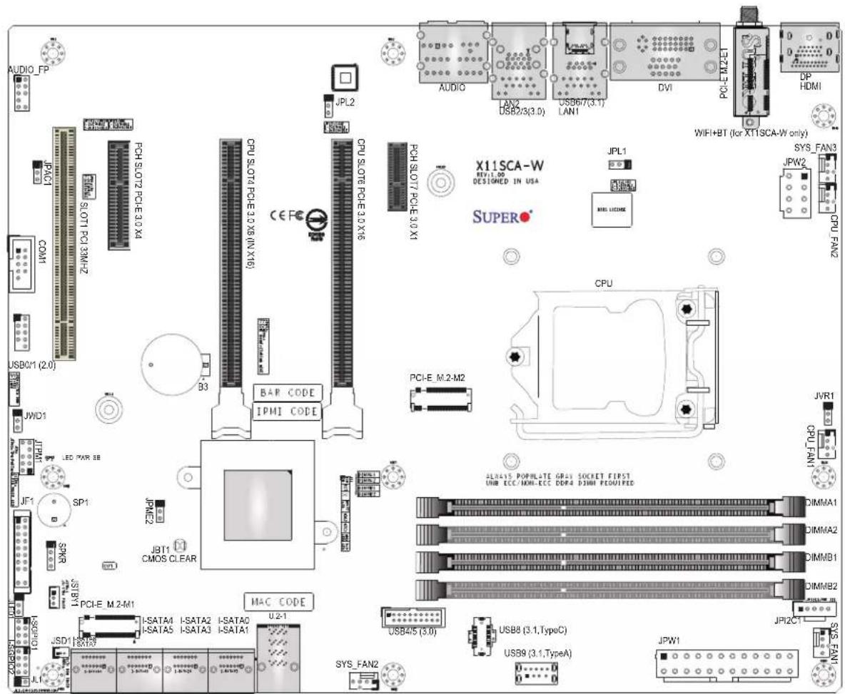
text_image
AUDIO_FP JPLC1 SLOT1 PCI 32MHz COM1 USB0/1 (2.0) JWD1 JF1 SP1 SPAR USB1/1 I-SD0/1 LED PAR 8B PCI-E M.2-M1 I-SATA4 I-SATA2 I-SATA0 U2-1 SATA9 U2-1 MAC CODE JPL2 CPU.SLOT4 PCHE10 X6 (IN X16) PCH.SLOT2 PCHE30 X4 B3 CPU.SLOT4 PCHE10 X6 (IN X16) CE FC X11SCA-W REV: 1.00 DESIGNED IN USA SUPER JPL1 PCH.SLOT7 PCHE 3.0 X1 PCI-E M.2-M2 CPU JVR1 CPU_FAN1 JPW2 JPYI2C1 JPS_FAN1 USB45 (3.0) USB8 (3.1,TypeC) USB9 (3.1,TypeA) JPYI SYS_FAN3 JPRW2 CPU_FAN2 WIFI+BT (for XT1SCA-W only)
Note: Components not documented are for internal testing only.
Figure 1-3. X11SCA-F Motherboard Layout
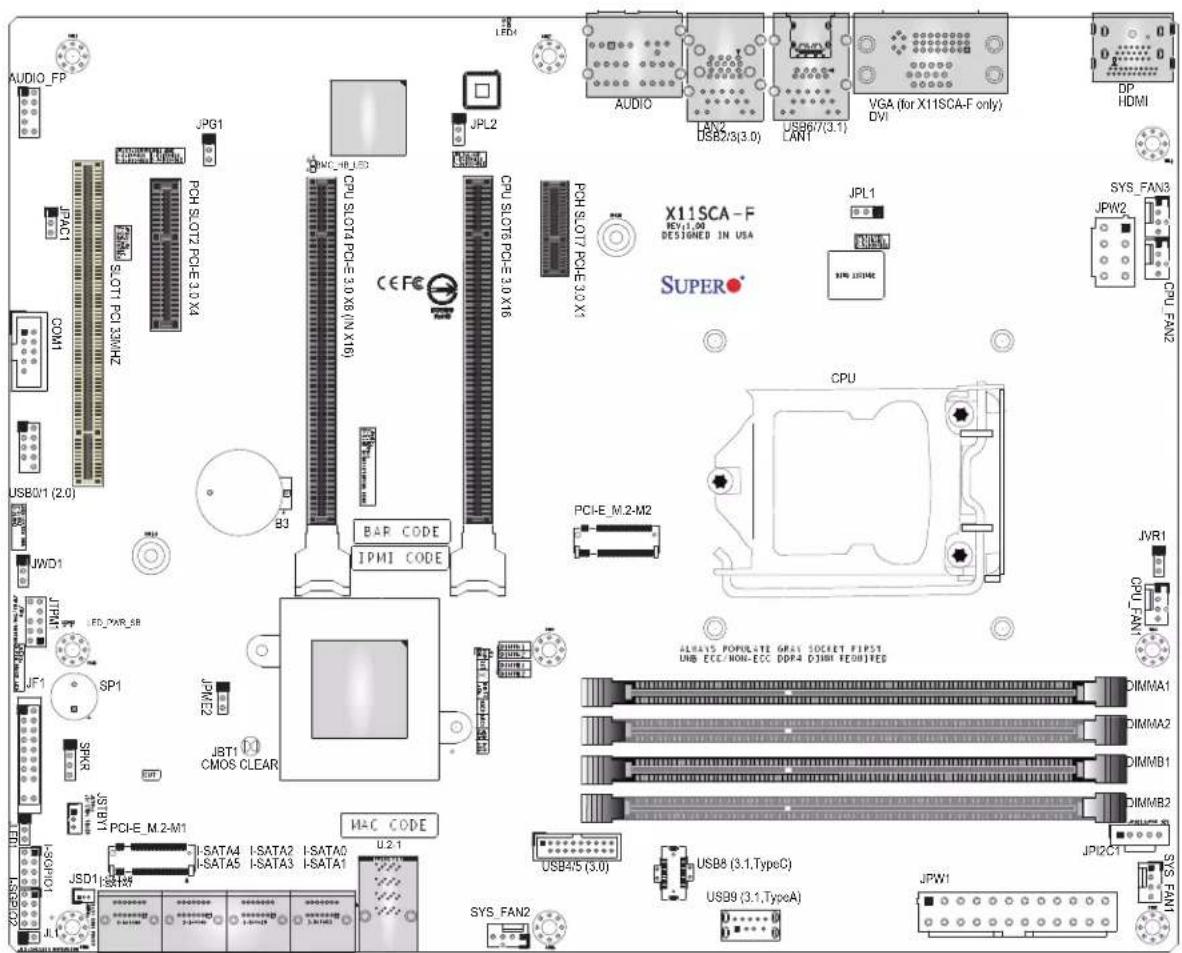
text_image
AUDIO_FP JPG1 PCH_SLOT7_PCE-30_X4 COM1 USB01 (2.0) JWD1 JPH1 FD_2AR_SB JF1 SP1 SPKG JSD1 I-SATA4 I-SATA5 I-SATA3 I-SATA0 I-SATA1 JCP1E_M 2-M1 JSD1 IS1189 JPL2 CPU_SLOT4_PCE-3.0 X8 (IN X16) B3 JMC_HDL53 CEFE CPU_SLOT6_PCE-3.0 X16 JPC-E_2 JST1 CMOS CLEAR BAR CODE IPMI CODE MAC_CODE U2.1 LED4 AUDIO LAN2 DSB2/3(3.0) US96/7(3.1) LANT VGA (for X11SCA-F only) DVI DP HDMI X11SCA-F REV:1.00 DESIGNED IN USA SUPER JPL1 SVM 202406C CPU-E_M.2-M2 JVR1 CPU_FAN1 ALWAYS POPULATE GRAY SOCKET FIPS3 UNB ECC/NON-ECC DDR4 DIMM TEOHITES DIMMA1 DIMMA2 DIMMB1 DIMMB2 JPI2C1 JPM1 SYS_FAN1
Note: Components not documented are for internal testing only.
Quick Reference

text_image
AUDIO_FP JPG1 JPAC1 SLOT1 COM1 USB0/1 B3 JWD1 JTPM1 LED_PWR_SB SP1 JPME2 JF1 JBT1 SPKR PWR_LED JSTBY1 JLED1 I-SGPIO1 I-SGPIO2 JL1 JSD1 I-SATA6 I-SATA7 M.2-M1 I-SATA2 I-SATA3 I-SATA4 I-SATA5 JMC_HB_LED SLOT2 SLOT4 SLOT6 SLOT7 LED4 JPL2 LED4 LAN2 USB2/3 LAN1 USB6/7 VGA DVI M.2-E1 DP HDMI X11SCA NO:1.1E RESTAINED IN USA SUPER CPU_SLOTPC-3.0 X1 PCI-E M2-M2 CPU_SLOTPC-3.0 X1 PCI-E M2-M2 USB4/5 USB8 USB9 JPW1 JPL1 SYS_FAN3 JPW2 CPU_FAN2 M.2-M2 JVR1 CPU_FAN1 DIMMA1 DIMMA2 DIMMB1 DIMMB2 JPI2C1 SYS_FAN1
Notes:
- See Chapter 2 for detailed information on jumpers, I/O ports, and JF1 front panel connections.
- "■" indicates the location of Pin 1.
- Jumpers/LED indicators not indicated are used for testing only.
- When PWR_LED (Onboard Power LED indicator) is on, system power is on. Unplug the power cable before installing or removing any components.
Quick Reference Table
Jumper Description Default Setting
| JBT1 Clear CMOS Short: Clear CMOS | Open: Normal | |
| JPAC1 Audio Enable Pins 1-2 (Enabled) | ||
| JPG1 | BMC GFX Chip Disable (X11SCA-F only) | Pins 1-2 (Enabled) |
| JPL1 LAN1 Enable Pins 1-2 (Enabled) | ||
| JPL2 LAN2 Enable Pins 1-2 (Enabled) | ||
| JPME2 Manufacturing Mode Select Pins 1-2 (Normal) | ||
| JWD1 Watch Dog Enable | Pins 1-2 (Reset) | |
| LED | Description | Status |
| BMC_HB_LED | BMC Heartbeat LED (X11SCA-F only) | Green Blinking: Normal |
| LED4 | UID LED (X11SCA-F only) | Blue: Unit Identified |
| LED_PWR_SB | Standby Power LED | Green: P3V3 Standby Power Ready |
| PWR_LED | Onboard Power LED | Green: Power On |
| Connector | Description |
| AUDIO_FP | Front Panel Audio Header |
| B3 | Onboard Battery |
| COM1 | COM1 Header |
| CPU SLOT4 PCI-E 3.0 x8 (IN x16) | PCIe x16 Slot (PCIe 3.0 x8 link) |
| CPU SLOT6 PCI-E 3.0 x16 | PCIe x16 Slot (PCIe 3.0 x16 link; x8 link when SLOT4 is in use) |
| PCH SLOT7 PCI-E 3.0 x1 | PCIe x1 Slot |
| PCH SLOT2 PCI-E 3.0 x4 | PCIe x4 Slot (shared with M.2-M1) |
| PCI SLOT1 33MHz | PCI Slot, 32 Bit/ 33 MHz with 5V single voltage |
| DP | Back Panel DisplayPort |
| DVI | Digital Video Interface |
| CPU_FAN1~2 CPU Fan Headers | |
| SYS_FAN1~3 | System Fan Headers |
| HD AUDIO | Back Panel HD Audio Connectors |
| HDMI | Back Panel HDMI Port |
| I-SATA0 ~ I-SATA7 | SATA 3.0 Ports via Intel PCH (6Gb/s) |
| I-SGPIO 1/2 | Serial Link General Purpose I/O Connection Headers for I-SATA 3.0 connections (I-SGPIO1 is for I-SATA0~3; I-SGPIO2 is for I-SATA4~5) |
| JF1 | Front Control Panel Header |
| JL1 | Chassis Intrusion Header |
| JLED1 3-pin Power LED Indicator Header | |
| JPW1 | 24-pin ATX Main Power Connector (Required) |
Connector Description
| JPW2 +12V 8-pin CPU Power Connector (Required) | |
| JSD1 SATA Disk On Module (DOM) Power Connector | |
| JSTBY1 Standby Power Header | |
| JTPM1 Trusted Platform Module (TPM)/Port 80 Connector | |
| LAN1/LAN2 1 Gigabit (RJ45) LAN Ports | |
| PCI-E_M.2-M1,PCI-E_M.2-M2 | PCIe M.2 M-key Sockets. Small form factor devices and other portable devices for high speed NVMe SSDs (see Section 2.8 Connectors) |
| PCI-E_M.2-E1 | PCIe M.2 E-key Socket for WiFi and Bluetooth (Pre-installed, X11SCA-W only) |
| SP1 Internal Speaker/Buzzer | |
| SPKR Header for Speaker/Buzzer (Pins 1~4: External Speaker, Pins 3~4: Buzzer) | |
| U.2-1 U.2 Port for U.2 NVMe Drives | |
| USB 0/1 Front Accessible USB 2.0 Header | |
| USB 2/3 Back Panel USB 3.1 Gen 1 Ports | |
| USB 4/5 Front Accessible USB 3.0 Header | |
| USB 6/7 Back Panel USB 3.1 Gen 2 Ports (USB6: Type-C, USB7: Type-A) | |
| USB 8 Front Accessible USB 3.1 Gen 2 Type-C Header | |
| USB 9 Front Accessible USB 3.1 Gen 2 Type-A Header | |
| VGA Back Panel VGA Port (X11SCA-F only) | |
Motherboard Features
| Motherboard Features | |
| CPU | |
| Supports a single Intel Xeon E, Core i3/i5/i7/i9, Pentium, and Celeron series processor in an LGA1151 (H4) socket and a thermal design power (TDP) of up to 95W | |
| Memory | |
| Four 288-pin DIMM slots support up to 128GB of DDR4 unbuffered ECC/non-ECC memory with speeds of up to 2666 MHz | |
| DIMM Size | |
| 32GB, 16GB, 8GB, and 4GB (up to a combined 128GB)Note 1: Memory speed supports depends on the processor used in the system.###Note 2: For the latest CPU/memory updates, please refer to our website at http://www.super-micro.com/products/motherboard. | |
| Chipset | |
| Intel C246 | |
| Expansion Slots | |
| Two PCIe 3.0 x16 slots (PCIe Links is NA/16 or 8/8)One PCIe 3.0 x4 slot (shared with M.2-M1)One PCIe 3.0 x1 slotOne PCI 33 MHz slotTwo M.2 M-key socketsOne M.2 E-key socket (for WiFi and bluetooth; X11SCA-W only)One U.2 slot (shared with M.2-M2) | |
| Network | |
| Two Intel 1G LAN ports on the I/O back panel (i210AT + i219LM(vPro)) | |
| Baseboard Management Controller (BMC) | |
| ASPEED AST2500 Baseboard Management Controller (BMC) supports IPMI 2.0 (X11SCA-F only)One IPMI LAN shared with LAN2 on the I/O back panel (X11SCA-F only) | |
| Graphics | |
| Graphics controller via ASPEED AST2500 BMC (X11SCA-F only) | |
| I/O Devices | |
| Serial (COM) Connection | One front accessible serial port header (COM1) |
| SATA 3.0 • Eight SATA | 3.0 ports (I-SATA0~7) |
| RAID (PCH) • RAID 0, | 1, 5, and 10 |
| Motherboard Features |
| Peripheral Devices |
| One USB 3.1 Gen 2 10G Type-C port on I/O back panel (with MUX)One USB 3.1 Gen 2 10G Type-A port on I/O back panelOne front accessible USB 3.1 Gen 2 Type-C header (with MUX)One front accessible USB 3.1 Gen 2 Type-A headerTwo USB 3.1 Gen 1 ports on I/O back panelTwo front accessible USB 3.1 Gen 1 connections via one headerTwo front accessible USB 2.0 connections via one header |
| BIOS |
| 256Mb AMI BIOS® SPI Flash BIOSDMI 3.0, ACPI 3.0+, USB Keyboard, Real Time Clock wake-up, PCI F/W 3.0, SPI dual/quad speed support, and SMBIOS 2.7+ |
| Power Management |
| ACPI power managementCPU fan auto-off in sleep modePower button override mechanismPower-on mode for AC power recovery |
| System Health Monitoring |
| Onboard voltage monitors for CPU cores, +1.8V, +3.3V, +5V, +/-12V, +3.3V Stdby, +5 Stdby, VBAT, HT, Memory, PCH Temperature, System Temperature, and Memory TemperatureCPU 5+2-phase switching voltage regulatorCPU/System overheat controlCPU Thermal Trip support |
| Fan Control |
| Five 4-pin fan headersFan status monitoring with firmwareMulti-speed fan control via onboard BMC |
| System Management |
| PECI (Platform Environment Configuration Interface) 3.1 supportIPMI 2.0 (X11SCA-F only)SuperDoctor® 5, Watch Dog, NMIChassis Intrusion header and detectionPower supply monitoring |
| LED Indicators |
| CPU/system overheat LEDPower/suspend-state indicator LEDFan failed LEDHDD activity LEDLAN activity LED |
| Other |
| RoHS |
| Dimensions |
| ATX form factor (12 x 9.6) (304.8 mm x 243.84 mm) |

Note 1: The CPU maximum thermal design power (TDP) is subject to chassis and heatsink cooling restrictions. For proper thermal management, please check the chassis and heatsink specifications for proper CPU TDP sizing.
Note 2: For IPMI configuration instructions, please refer to the Embedded IPMI Configuration User's Guide available at http://www.supermicro.com/support/manuals/.
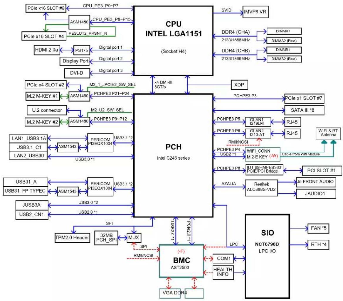
Figure 1-4. Chipset Block Diagram
flowchart
graph TD
    A["CPU INTEL LGA1151 (Socket H4)"] -->|SVID| B["IMVP8 VR"]
    A -->|DDR4 (CHA) 2133/1866MHz| C["DIMMA1"]
    A -->|DDR4 (CHB) 2133/1866MHz| D["DIMMA2 (Blue)"]
    A -->|XDP| E["PCH Intel C246 series"]
    A -->|PCHPE3 P3| F["PCIe x1 SLOT #7"]
    A -->|PCHPE3 P5| G["GLAN1 I219LM"]
    A -->|PCHPE3 P6| H["GLAN2 I210-AT"]
    A -->|RMII/NCSI| I["WIFI_CONN M.2-E KEY (-W)"]
    A -->|RJ45| J["Cable from WiFi Module"]
    A -->|RJ45| K["WIFI & BT Antenna"]
    A -->|PCHPE3 P4 USB2 *1| L["PCIe x1 SLOT #7"]
    A -->|PCHPE3 P8 IDT 88HMPEB383 PCIE/PCI Bridge| M["PCIe x1 SLOT #7"]
    A -->|AZALIA| N["Realtek ALC888S-VD2"]
    A --> O["SIO NCT6796D LPC I/O"]
    A -->|LPC| P["COM1 HEALTH INFO"]
    A --> Q["(-F) BMC AST2500"]
    Q --> R["VGA DDR4"]
    Q --> S["SPI 32MB PCH_SPI"]
    Q --> T[USB2.0 *1 USB3.0 *2 USB3.1 *2 USB3.0 *1 USB3.1 *2 USB3.0 *1 USB3.0 *2 USB3.1 *2 USB3.0 *1 USB3.0 *2 USB3.0 *2 USB3.0 *2 USB3.0 *2 USB3.0 *2 USB3.0 *2 USB3.0 *2 USB3.0 *2 USB3.0 *2 USB3.0 *2 USB3.0 *2 USB3.0 *2 USB3.0 *2 USB3.0 *2 USB3.0 *2 USB3.0 *2 USB3.0 *2 USB3.1 *2 USB3.1 *2 USB3.1 *2 USB3.1 *2 USB3.1 *2 USB3.1 *2 USB3.1 *2 USB3.1 *2 USB3.1 *2 USB3.1 *2 USB3.1 *2 USB3.1 *2 USB3.1 *2 USB3.1 *2 USB3.1 *2 USB3.1 *2 USB3.1 *2 USB4
    A -->|PCIe x16 SLOT #6| B
    A -->|PCIe x16 SLOT #4| C
    A -->|PCIe x4 SLOT #2| D
    A -->|M.2 M-KEY #1| E
    A -->|U.2 connector| F
    A -->|M.2 M-KEY #2| G
    A -->|LAN1_USB3.1A | H
    A -->|USB3.1_C1 | I
    A -->|LAN2_USB30 | J
    A -->|USB31_A | K
    A -->|USB31_FP TYPEC| L
    A -->|JUSB3A | M
    A -->|USB2_CN1| N
    A -->|TPM2.0 Header| O
    A -->|SPI 32MB PCH_SPI| P
    A -->|MUX 32MB PCH_SPI| Q
    A -->|SPI RMII/NCSI| R
    A -->|VGA DDR4| S

Note: This is a general block diagram and may not exactly represent the features on your motherboard. See the previous pages for the actual specifications of your motherboard.
1.2 Processor and Chipset Overview
Built upon the functionality and capability of the Intel Xeon E, Core i3/i5/i7/i9, Celeron, and Pentium series processors (Socket LGA 1151) and the Intel C246, the X11SCA/-W/-F motherboard offers maximum I/O expandability, energy efficiency, and data reliability in a 14-nm process architecture. It is optimized for all workstation applications, for example, 3D modeling, rendering, video editing, engineering simulation, and automation.
The Intel Xeon-E and PCH C246 platform supports the following features:
• ACPI Power Management
- Intel Turbo Boost Technology 2.0, Power Monitoring/Power Control, and Platform Power Control
• Adaptive Thermal Management/Monitoring
- PCIe 3.0, SATA 3.0 with transfer rates of up to 6 Gb/s, xHCI USB w/SuperSpeed 3.1
• System Management Bus (SMBus) Specification, Version 2.0
• Intel Trusted Execution Technology (Intel TXT)
• Intel Rapid Storage Technology
• Intel Virtualization Technology for Directed I/O (Intel VT-d)
1.3 Special Features
This section describes the health monitoring features of the X11SCA/-W/-F motherboard. The motherboard has an onboard System Hardware Monitor chip that supports system health monitoring.
Recovery from AC Power Loss
The Basic I/O System (BIOS) provides a setting that determines how the system will respond when AC power is lost and then restored to the system. You can choose for the system to remain powered off (in which case you must press the power switch to turn it back on), or for it to automatically return to the power-on state. See the Advanced BIOS Setup section for this setting. The default setting is Last State.
1.4 System Health Monitoring
Onboard Voltage Monitors (X11SCA-F only)
The onboard voltage monitor will continuously scan crucial voltage levels. Once a voltage becomes unstable, it will give a warning or send an error message to the screen. Users can adjust the voltage thresholds to define the sensitivity of the voltage monitor. Real time readings of these voltage levels are all displayed in BIOS.
Fan Status Monitor with Firmware Control
The system health monitor chip can check the RPM status of a cooling fan. The CPU and chassis fans are controlled by BIOS Thermal Management.
Environmental Temperature Control (X11SCA-F only)
System health sensors monitor temperatures and voltage settings of onboard processors and the system in real time via the IPMI interface. Whenever the temperature of the CPU or the system exceeds a user-defined threshold, system/CPU cooling fans will be turned on to prevent the CPU or the system from overheating

Note: To avoid possible system overheating, please be sure to provide adequate airflow to your system.
System Resource Alert
This feature is available when used with SuperDoctor 5 in the Windows OS or in the Linux environment. SuperDoctor is used to notify the user of certain system events. For example, you can configure SuperDoctor to provide you with warnings when the system temperature, CPU temperatures, voltages, and fan speeds go beyond a predefined range.
1.5 ACPI Features
ACPI stands for Advanced Configuration and Power Interface. The ACPI specification defines a flexible and abstract hardware interface that provides a standard way to integrate power management features throughout a computer system, including its hardware, operating system and application software. This enables the system to automatically turn on and off peripherals such as CD-ROMs, network cards, hard disk drives and printers.
In addition to enabling operating system-directed power management, ACPI also provides a generic system event mechanism for Plug and Play, and an operating system-independent interface for configuration control. ACPI leverages the Plug and Play BIOS data structures, while providing a processor architecture-independent implementation that is compatible with appropriate Windows operating systems.
1.6 Power Supply
As with all computer products, a stable power source is necessary for proper and reliable operation. It is even more important for processors that have high CPU clock rates.
The X11SCA/-W/-F motherboard accommodates 24-pin ATX power supplies. Although most power supplies generally meet the specifications required by the CPU, some are inadequate. In addition, one 12V 8-pin power connection is also required to ensure adequate power supply to the system.

Warning: To avoid damaging the power supply or the motherboard, be sure to use a power supply that contains a 24-pin and 8-pin power connector. Be sure to connect the power supplies to the 24-pin power connector (JPW1), and the 8-pin power connector (JPW2) on the motherboard. Failure in doing so may void the manufacturer warranty on your power supply and motherboard.
It is strongly recommended that you use a high quality power supply that meets ATX power supply Specification 2.02 or above. It must also be SSI compliant.
1.7 Serial Port
The X11SCA/-W/-F motherboard supports one serial communication connection. COM port header 1 (COM1) can be used for input/output. The UART provides legacy speeds with a baud rate of up to 115.2 Kbps.
Chapter 2
Installation
2.1 Static-Sensitive Devices
Electrostatic Discharge (ESD) can damage electronic components. To prevent damage to your motherboard, it is important to handle it very carefully. The following measures are generally sufficient to protect your equipment from ESD.
Precautions
- Use a grounded wrist strap designed to prevent static discharge.
- Touch a grounded metal object before removing the board from the antistatic bag.
- Handle the board by its edges only; do not touch its components, peripheral chips, memory modules or gold contacts.
- When handling chips or modules, avoid touching their pins.
- Put the motherboard and peripherals back into their antistatic bags when not in use.
- For grounding purposes, make sure your computer chassis provides excellent conductivity between the power supply, the case, the mounting fasteners and the motherboard.
- Use only the correct type of onboard CMOS battery. Do not install the onboard battery upside down to avoid possible explosion.
Unpacking
The motherboard is shipped in antistatic packaging to avoid static damage. When unpacking the motherboard, make sure that the person handling it is static protected.
2.2 Motherboard Installation
All motherboards have standard mounting holes to fit different types of chassis. Make sure that the locations of all the mounting holes for both the motherboard and the chassis match. Although a chassis may have both plastic and metal mounting fasteners, metal ones are highly recommended because they ground the motherboard to the chassis. Make sure that the metal standoffs click in or are screwed in tightly.
Tools Needed


Phillips Screwdriver (1) Standoff Silips Screws (9)
Only if Needed
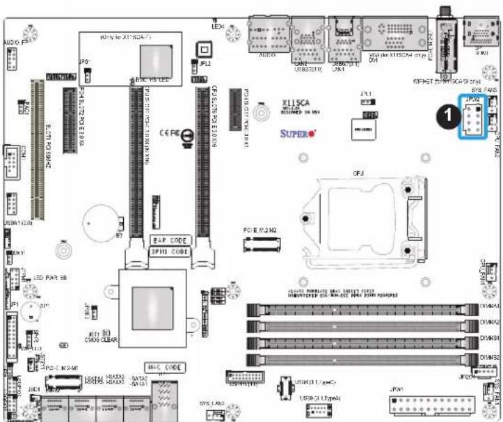
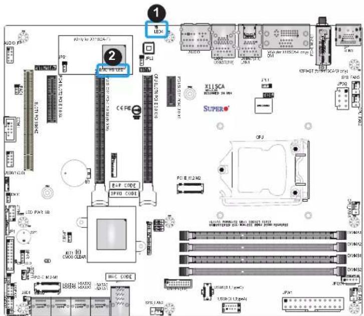
Location of Mounting Holes

text_image
(Only for X11SCA-F) JPG1 BMC HS LED CPU SLC01/PCI-E 33 X6 JIN X10 CPU SLC07/PCI-E 33 X6 SLOT PCI 33M1Z SLOT PCI 33M2Z USB01 (2.0) S3 BAP CODE IPMI CODE X11SCA HIV-LIP RESIGNED IN USA SUPER CPU PCI-E M-2.M2 LED PWR_SB JF1 8P1 JST1 CMOS CLEAR JSD1 SATA4 I-SATA2 I-SATA0 U2-T SATA5 I-SATA3 I-SATA1 MAC CODE JSPX LED PWR_SB JSPX JSD1 SATA4 I-SATA2 I-SATA0 U2-T SATA5 I-SATA3 I-SATA1 USB4/5 (3.0) USB8 (3.1,TypeC) USB9 (3.1,TypeA) JPN1 JPN2CT JPN2 VGA (for X11SCA-F only) DVI LED0 LAN2 USB2(0.3.0) USBV(0.1) LAN1 LCTXI HDMI WIF+RT (for X11SCAAW only) JPL1 JPN2 SYS_FAN3 JPN2 RIN-FAN3 CPU_PN1 DIMMA1 DIMMA2 DIMMB1 DIMMB2 JPW1
Notes: 1. To avoid damaging the motherboard and its components, please do not use a force greater than 8 lb-inch on each mounting screw during motherboard installation.
- Some components are very close to the mounting holes. Please take precautionary measures to avoid damaging these components when installing the motherboard to the chassis.
Installing the Motherboard
- Locate the mounting holes on the motherboard. Refer to the previous page for the location.

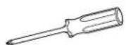
text_image
Chassis Chassis- Locate the matching mounting holes on the chassis. Align the mounting holes on the motherboard against the mounting holes on the chassis.
text_image
3x8 Motherboard Chassis 3x8 Motherboard Chassis-
Install standoffs in the chassis as needed.
-
Install the motherboard into the chassis carefully to avoid damaging other motherboard components.
-
Using the Phillips screwdriver, insert a Phillips head #6 screw into a mounting hole on the motherboard and its matching mounting hole on the chassis.
-
Repeat Step 5 to insert the remaining screws into all mounting holes.
-
Make sure that the motherboard is securely placed in the chassis.

Note: Images displayed are for illustration only. Your chassis or components might look different from those shown in this manual.
2.3 Processor and Heatsink Installation
Warning: When handling the processor package, avoid placing direct pressure on the label area of the fan.

Important:
- Always connect the power cord last, and always remove it before adding, removing or changing any hardware components. Make sure that you install the processor into the CPU socket before you install the CPU heatsink.
- If you buy a CPU separately, make sure that you use an Intel-certified multi-directional heatsink only.
- Make sure to install the motherboard into the chassis before you install the CPU heatsink.
- When receiving a motherboard without a processor pre-installed, make sure that the plastic CPU socket cap is in place and none of the socket pins are bent; otherwise, contact your retailer immediately.
• Refer to the Supermicro website for updates on CPU support.
Installing the LGA1151 Processor
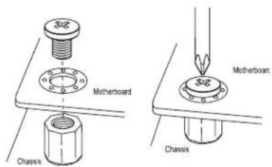
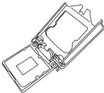
- Press the load lever to release the load plate, which covers the CPU socket, from its locking position.

text_image
Load Plate Load Lever
text_image
Load Plate 1 2- Gently lift the load lever to open the load plate. Remove the plastic cap.
natural_image
Technical line drawing of a mechanical component with internal cavities and mounting brackets (no text or symbols)- Use your thumb and your index finger to hold the CPU at the North center edge and the South center edge of the CPU.
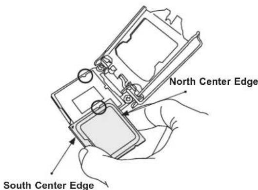
- Align the CPU key that is the semi-circle cutouts against the socket keys. Once it is aligned, carefully lower the CPU straight down into the socket. Do not drop the CPU on the socket. Do not move the CPU horizontally or vertically.

natural_image
Technical line drawing of a mechanical component with no visible text or symbols- Do not rub the CPU against the surface or against any pins of the socket to avoid damaging the CPU or the socket.

text_image
Pin 1-
With the CPU inside the socket, inspect the four corners of the CPU to make sure that the CPU is properly installed.
-
Use your thumb to gently push the load lever down to the lever lock.
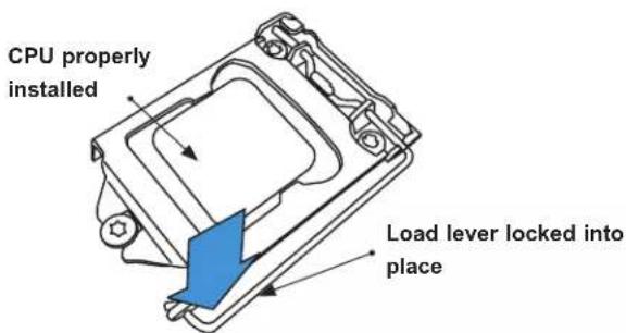
text_image
CPU properly installed Load lever locked into place
Note: You can only install the CPU inside the socket in one direction. Make sure that it is properly inserted into the CPU socket before closing the load plate. If it doesn't close properly, do not force it as it may damage your CPU. Instead, open the load plate again and double-check that the CPU is aligned properly.
Installing an Active CPU Heatsink with Fan
- Locate the CPU fan header (CPU_FAN1) on the motherboard.
- Position the heatsink so that the heatsink fan wires are closest to the CPU fan header and are not interfering with other components.
- Inspect the CPU fan wires to make sure they are routed through the bottom of the heatsink.
- Remove the thin layer of protective film from the heatsink. CPU overheating may occur if the protective film is not removed from the heatsink.
- Apply the proper amount of thermal grease on the CPU. If your heatsink came with a thermal pad, please ignore this step. Once the screws are tightened, plug the power cord into the CPU_FAN1 header.

text_image
Thermal Grease
natural_image
Technical line drawing of a mechanical component with no visible text or symbols
Note: Graphic drawings included in this manual are for reference only. They might look different from the components installed in your system.
- Align the four heatsink fasteners with the mounting holes on the motherboard. Gently push down the fasteners in a diagonal order (Example: #1 and #2, then #3 and #4) into the mounting holes until you hear a click. Then lock the fasteners by turning each one 90° clockwise.
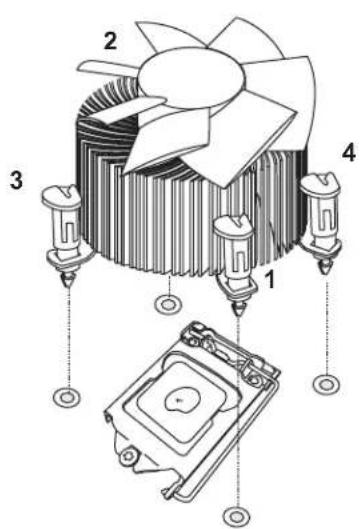
text_image
Technical diagram of a cooling fan assembly with numbered components and exploded view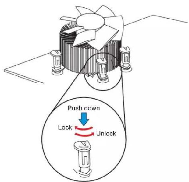
text_image
Push down Lock Unlock- Once all four fasteners are secured, connect the heatsink fan wire connector to the CPU fan header.
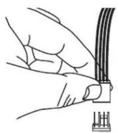
natural_image
Line drawing of hands connecting a cable to a connector (no text or symbols)Removing a Heatsink

Note: We do not recommend that the CPU or heatsink be removed. However, if you do need to remove the heatsink, please follow the instructions below to remove the heatsink and prevent damage done to the CPU or other components.
- Unplug the power connector from the power supply.
- Disconnect the heatsink fan connector from the CPU fan header.
- Gently press down each fastener cap and turn them 90^ counter clockwise, then pull the fasteners upwards to loosen them.
- Remove the heatsink from the CPU.

text_image
Pull up Lock Unlock2.4 Memory Support and Installation

Note: Check the Supermicro website for recommended memory modules.

Important: Exercise extreme care when installing or removing DIMM modules to prevent any possible damage.
Memory Support
The X11SCA/-W/-F motherboard supports up to 128GB of unbuffered, ECC/non-ECC DDR4 with speeds of up to 2666 MHz memory in four memory slots. Populating these DIMM slots with memory modules of the same type and size will result in interleaved memory, which will improve memory performance.
Installing DDR4 Memory
- Insert the desired number of DIMMs into the memory slots, starting with DIMMA2, then DIMMB2, DIMMA1, and DIMMB1. For the system to work properly, please use the memory modules of the same type and speed.
- Push the release tab outwards on the end of the DIMM slot to unlock it.
- Align the key of the DIMM module with the receptive point on the memory slot.
- Use two thumbs together to press the notches on both ends of the module straight down into the slot until the module snaps into place.
- Press the release tab to the lock position to secure the DIMM module into the slo.
Removing Memory Modules
Reverse the steps above to remove the DIMM modules from the motherboard.
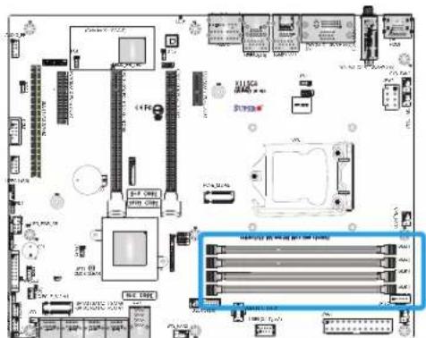
text_image
Circuit board layout diagram with labeled components and a highlighted component box showing internal circuit connections.
natural_image
Technical illustration of a mechanical component with a blue arrow indicating a feature, no visible text or symbols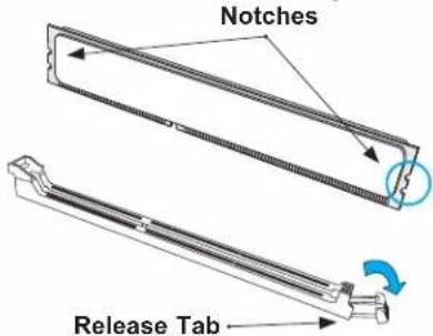
text_image
Notches Release Tab
text_image
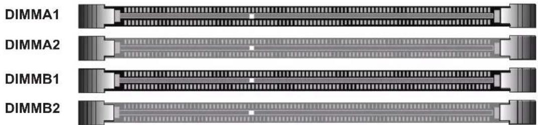
Insert the DIMM module into the memory slot.DIMM Module Population Sequence
When installing memory modules, the DIMM slots should be populated in the following order: DIMMA2, DIMMB2, DIMMA1, DIMMB1.
• Always use DDR4 DIMM modules of the same type and size.
- Mixed DIMM speeds can be installed. However, all DIMMs will run at the speed of the slowest DIMM.
- The motherboard will support odd-numbered modules (one or three modules installed). However, for best memory performance, install DIMM modules in pairs to activate memory interleaving.

Towards the CPU
text_image
DIMMA1 DIMMA2 DIMMB1 DIMMB2| Recommended Population (Balanced) | ||||
| DIMMA1 DIMMB1 DIMMA2 | DIMMB2 Total | System Memory | ||
| 4GB DIMM 4GB DIMM 8GB | ||||
| 4GB DIMM 4GB DIMM 4GB DIMM 4GB DIMM 16GB | ||||
| 8GB DIMM 8GB DIMM 16GB | ||||
| 8GB DIMM 8GB DIMM 8GB DIMM 8GB DIMM 32GB | ||||
| 16GB DIMM 16GB DIMM 32GB | ||||
| 16GB DIMM 16GB DIMM 16GB | DIMM 16GB DIMM 64GB | |||
| 32GB DIMM 32GB DIMM 64GB | ||||
| 32GB DIMM 32GB DIMM 32GB | DIMM 32GB DIMM 128GB | |||
2.5 M.2 Installation (optional)
Follow the instructions below to properly install an optional M.2 device.

Note: The length of the M.2 device being installed will affect the installation process below.

text_image
A Holder Locked position B Holder Mount Turn 90 degrees to lock Locked position C Card Holder Mount Turn 90 degrees to lock Locked position with M.2 card D Plastic screw STOPFigure 2-1. M.2 Holder Configurations
- Determine the appropriate installation location on the M.2 holder, based on the M.2 device length.

Note: Follow steps 2-3 for full-length M.2 devices.
-
Slot M.2 device into M.2 connector and lay flat on M.2 holder (Figure 2-1, Section A).
-
Secure the M.2 device using the plastic screw. Do not over-torque the screw (Figure 2-1, Section D).

Note: Follow steps 4-6 for M.2 devices that are shorter than full-length.
-
Install a card holder mount into the appropriate mounting position on the M.2 holder (Figure 2-1, Section C). Turn 90 degrees to lock the mount into position.
-
Slot M.2 device into M.2 connector and lay flat on M.2 holder (Figure 2-1, Section A).
-
Push the pin end of the card holder mount into the pin receptacle on the card holder mount. The pin will snap into position when pushed enough (Figure 2-1, Section C).
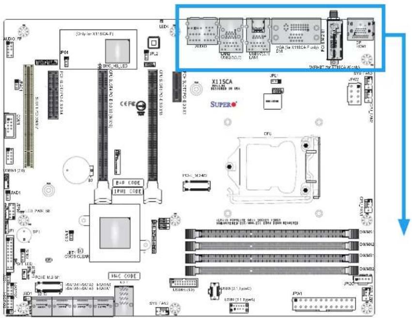
2.6 Rear I/O Ports
Refer to Figure 2-2 below for the locations and descriptions of the various I/O ports on the rear of the motherboard.
text_image
A100 FF [Oblay or XT-SCA Fi] P61 SNC HB LED JP.2 CE FC X11SCA SUPERO CPU CPU 500 PC 3.0/31 USB1 (2.0) LED CJ4 SP1 SP1 LED CPLE N.2 V1 HC CODE USB1 SNC HB LED JPG LED CJ4 SP1 SP1 LED CPLE N.2 V1 HC CODE USB1 SNC HB LED JPG LED CJ4 SP1 SP1 LED CPLE N.2 V1 HC CODE USB1 SNC HB LED JPG LED CJ4 SP1 SP1 LED CPLE N.2 V1 HC CODE USB1Figure 2-2. I/O Port Locations and Definitions

text_image
Diagram showing 17 computer ports with labels and connection arrows, likely illustrating a network or system architecture.| Rear I/O Ports | |||||||
| # | Description | # | Description | # | Description | # | Description |
| 1 | DisplayPort | 6 | LAN1 | 11 | USB2 (USB 3.1 Gen 1) | 16 | Line Out |
| 2 | HDMI 7 | USB7(USB 3.1 Gen 2 Type-A) | 12 | Center/LFE Out | 17 | Mic In | |
| 3 | WiFi + BT(X11SCA-W only) | 8 | USB6(USB 3.1 Gen 2 Type-C) | 13 | Surround Out | ||
| 4 | VGA(X11SCA-F only) | 9 | LAN2 | 14 | SPDIF Out | ||
| 5 | DVI | 10 | USB3 (USB3.1 Gen 1) | 15 | Line In | ||
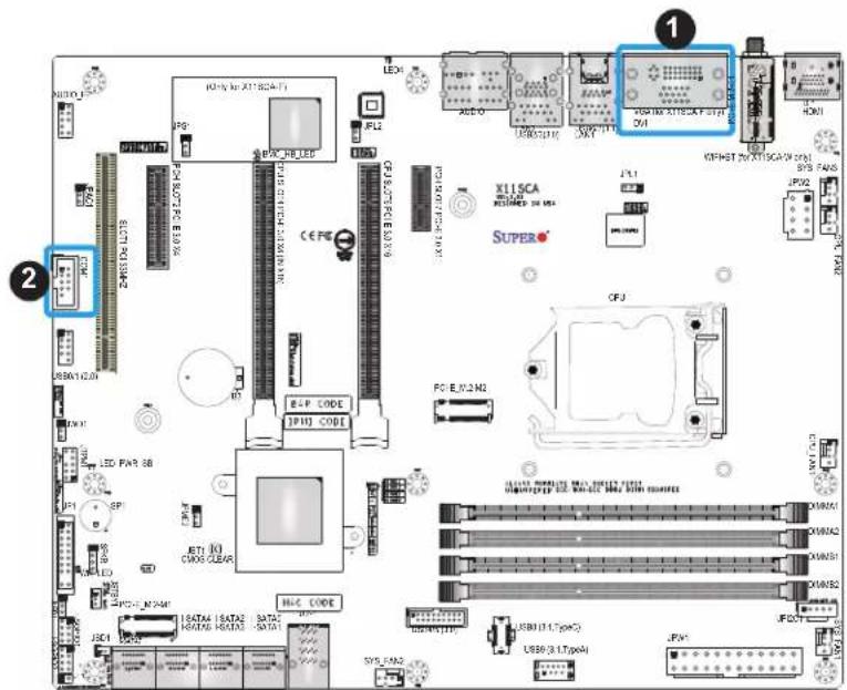
VGA/DVI Ports (X11SCA-F only)
The VGA and DVI ports are located on the left of LAN1 on the I/O back panel. Refer to the layout below for the locations.
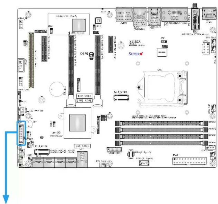
COM Port Header
One COM connection (COM1) is located on the motherboard. Refer to the table below for pin definitions.
| COM Port HeaderPin Definitions | |||
| Pin# Definition Pin# Definition | |||
| 1 DCD | 6 DSR | ||
| 2 RXD | 7 RTS | ||
| 3 TXD | 8 CTS | ||
| 4 DTR | 9 RI | ||
| 5 Ground | 10 N/A | ||
text_image
Labeled diagram of an electronic circuit board with component labels and connectors- VGA/DVI Ports
2.COM1
Universal Serial Bus (USB) Ports
There are two USB 3.1 Gen 1 ports (USB2/3) and two USB 3.1 Gen 2 ports (USB6/7) located on the I/O back panel. The motherboard also has two front access USB headers (USB0/1: USB 2.0, USB4/5: USB 3.1 Gen 1) and two front access USB 3.1 headers (USB8 and USB9). The USB8 header supports Type-C and USB9 supports Type-A. The onboard headers can be used to provide front side USB access with a cable (not included).
| Front Panel USB 0/1 (2.0)Pin Definitions | ||
| Pin# Definition Pin# Definition | ||
| 1 +5V 2 +5V | ||
| 3 USB_N 4 USB_N | ||
| 5 USB_P 6 USB_P | ||
| 7 Ground 8 Ground | ||
| 9 Key 10 NC | ||

Note: USB wake up capabilities are limited to the USB0/1 header and USB7 port. USB wake up is enabled by default in the BIOS. Disabling this feature must be completed in the operating system.
| Type-A USB9 (3.1 Gen 1)Pin Definitions | ||
| Pin# Definition Pin# Definition | ||
| 1 VBUS 5 SSRX- | ||
| 2 USB_N 6 SSRX+ | ||
| 3 USB_P 7 GND | ||
| 4 Ground 8 SSTX- | ||
| 9 SSTX+ | ||
| Back Panel USB 2/3 (3.1 Gen 1)Pin Definitions | |||
| Pin# | Definition | Pin# | Definition |
| A1 | VBUS | B1 | Power |
| A2 | D- | B2 | USB_N |
| A3 | D+ | B3 | USB_P |
| A4 | GND | B4 | GND |
| A5 | Stda_SSRX- | B5 | USB3_RN |
| A6 | Stda_SSRX+ | B6 | USB3_RP |
| A7 | GND | B7 | GND |
| A8 | Stda_SSTX- | B8 | USB3_TN |
| A9 | Stda_SSTX+ | B9 | USB3_TP |

text_image
Labeled diagram of an electronic circuit board with component labels and connectors- USB0/1
- USB2/3
- USB4/5
- USB6/7
- USB8
- USB9
LAN Ports
Two Gigabit Ethernet ports (LAN1 and LAN2) are located on the I/O back panel of the motherboard. All of these ports accept RJ45 cables. Please refer to the Section 2.10 LED Indicators for LAN LED information.
| LAN PortPin Definitions | ||
| Pin# Definition Pin# Definition | ||
| 1 TX_D1+ 5 BI_D3- | ||
| 2 TX_D1- 6 RX_D2- | ||
| 3 RX_D2+ 7 BI_D4+ | ||
| 4 BI_D3+ 8 BI_D4- | ||

text_image
AUDIO LED PWR 2000000000000000000000000000000000000000000000000000000000000000000000000000000000000000 R1P R1C R1E R1F R2A R2B R2C R2D R2E R2F R3A R3B R3C R3D R3E R3F R4A R4B R4C R4D R4E R4F R5A R5B R5C R5D R5E R5F R6A R6B R6C R6D R6E R6F R7A R7B R7C R7D R7E R7F R8A R8B R8C R8D R8E R8F R9A R9B R9C R9D R9E R9F R10A R10B R10C R11A R11B R11C R12A R12B R12C R13A R13B R13C R14A R14B R14C R15A R15B R15C R16A R16B R16C R17A R17B R17C R18A R18B R18C R19A R19B R19C R20A R20B R20C R21A R21B R21C R22A R22B R22C R23A R23B R23C R24A R24B R24C R25A R25B R25C R26A R26B R26C R27A R27B R27C R28A R28B R28C R29A R29B R29C R30A R30B R30C R31A R31B R31C R32A R32B R32C R33A R33B R33C R34A R34B R34C R35A R35B R35C R36A R36B R36C R37A R37B R37C R38A R38B R38C R39A R39B R39C R40A R40B R40C R41A R41B R41C R42A R42B R42C R43A R43B R43C R44A R44B R44C R45A R45B R45C R46A R46B R46C R47A R47B R47C R48A R48B R48C R49A R49B R49C- LAN1
- LAN2
2.7 Front Control Panel
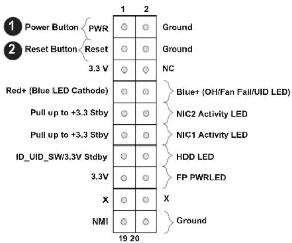
JF1 contains header pins for various buttons and indicators that are normally located on a control panel at the front of the chassis. These connectors are designed specifically for use with Supermicro chassis. Refer to the figure below for the descriptions of the front control panel buttons and LED indicators.
text_image
AUDIO FF PS1 CPU B: 600/800.5A SODING DIM/2 LED I/O 2700 LED I/O 2700 LED I/O 2700 LED I/O 2700 LED I/O 2700 LED I/O 2700 LED I/O 2700 LED I/O 2700 LED I/O 2700 LED I/O 2700 LED I/O 2700 LED I/O 2700Figure 2-3. JF1 Header Pins

text_image
Power Button PWR Reset Button Reset 3.3 V Red+ (Blue LED Cathode) Pull up to +3.3 Stby Pull up to +3.3 Stby ID_UID_SW/3.3V Stdby 3.3V X NMI 19 20 Ground Ground NC Blue+ (OH/Fan Fail/UID LED) NIC2 Activity LED NIC1 Activity LED HDD LED FP PWRLED GroundPower Button
The Power Button connection is located on pins 1 and 2 of JF1. Momentarily contacting both pins will power on/off the system. This button can also be configured to function as a suspend button (refer to Chapter 4). To turn off the power when the system is in suspend mode, press the button for four seconds or longer. Refer to the table below for pin definitions.
| Power ButtonPin Definitions (JF1) | |
| Pin# | Definition |
| 1 | Signal |
| 2 | Ground |
Reset Button
The Reset Button connection is located on pins 3 and 4 of JF1. Attach it to a hardware reset switch on the computer case. Refer to the table below for pin definitions.
| Reset ButtonPin Definitions (JF1) | |
| Pin# | Definition |
| 3 | Reset |
| 4 | Ground |
text_image
1 2 Power Button PWR Ground Reset Button Reset Ground 3.3 V NC Red+ (Blue LED Cathode) Blue+ (OH/Fan Fail/UID LED) Pull up to +3.3 Stby NIC2 Activity LED Pull up to +3.3 Stby NIC1 Activity LED ID_UID_SW/3.3V Stdby HDD LED 3.3V FP PWRLED X X NMI Ground 19 20-
PWR Button
-
Reset Button
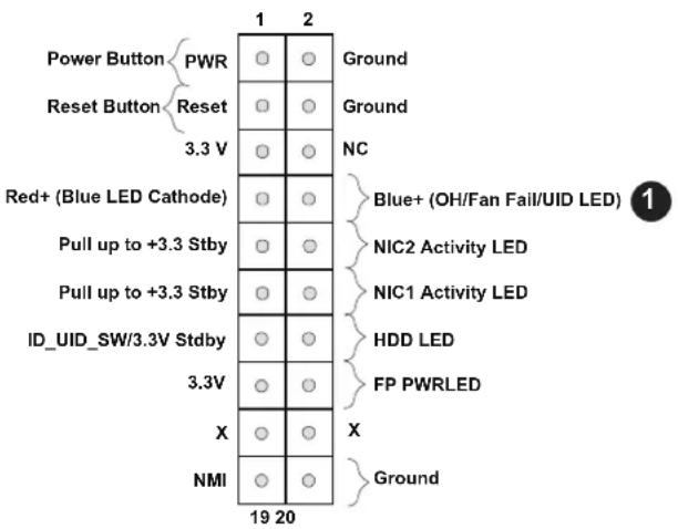
Overheat (OH)/Fan Fail
Connect an LED cable to pins 7 and 8 of the Front Control Panel to use the Overheat/Fan Fail LED connections. The LED on pin 8 provides warnings of overheat or fan failure. Refer to the tables below for pin definitions.
| OH/Fan Fail Indicator Status | |
| State | Definition |
| Off | Normal |
| On | Overheat |
| Flashing | Fan Fail |
| OH/Fan Fail LEDPin Definitions (JF1) | |
| Pin# | Definition |
| 7 Blue | LED |
| 8 OH/Fan Fail LED | |
text_image
Power Button PWR Reset Button Reset 3.3 V Red+ (Blue LED Cathode) Pull up to +3.3 Stby Pull up to +3.3 Stby ID_UID_SW/3.3V Stdby 3.3V X NMI 19 20 Ground Ground NC Blue+ (OH/Fan Fail/UID LED) NIC2 Activity LED NIC1 Activity LED HDD LED FP PWRLED Ground- OH/Fan Fail
The NIC (Network Interface Controller) LED connection for LAN port 1 is located on pins 11 and 12 of JF1, and the LED connection for LAN port 2 is on pins 9 and 10. Attach the NIC LED cables here to display network activity. Refer to the table below for pin definitions.
| LAN1/LAN2 LEDPin Definitions (JF1) | |
| Pin# | Definition |
| 9 Pull | up to +3.3 Stby |
| 10 NIC2 | Activity LED |
| 11 Pull | up to +3.3 Stby |
| 12 NIC1 | Activity LED |
HDD LED/UID Switch
The HDD LED connection is located on pins 13 and 14 of JF1. Attach a cable to pin 14 to show hard drive activity status. Attach a cable to pin 13 to use UID switch. Refer to the table below for pin definitions.
| HDD LEDPin Definitions (JF1) | |
| Pin# | Definition |
| 13 | 3.3V Stdby |
| 14 | HDD Active |

text_image
Power Button PWR Reset Button Reset 3.3 V Red+ (Blue LED Cathode) Pull up to +3.3 Stby Pull up to +3.3 Stby ID_UID_SW/3.3V Stdby 3.3V X NMI 19 20 Ground Ground NC Blue+ (OH/Fan Fail/UID LED) NIC2 Activity LED ① NIC1 Activity LED ② HDD LED ③ FP PWRLED X Ground- NIC2 LED
- NIC1 LED
- HDD LED / UID Switch
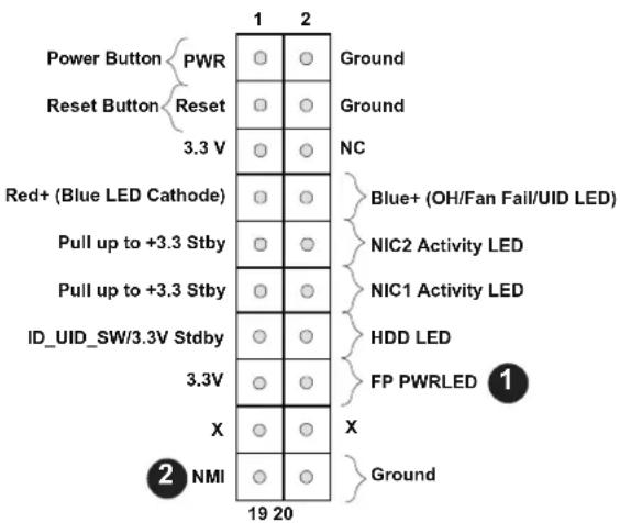
Power LED
The Power LED connection is located on pins 15 and 16 of JF1. Refer to the table below for pin definitions.
| Power LEDPin Definitions (JF1) | |
| Pin# | Definition |
| 15 | 3.3V |
| 16 | PWR LED |
NMI Button
The non-maskable interrupt button header is located on pins 19 and 20 of JF1. Refer to the table below for pin definitions.
| NMI ButtonPin Definitions (JF1) | |
| Pin# | Definition |
| 19 | Control |
| 20 | Ground |
text_image
Power Button PWR Reset Button Reset 3.3 V Red+ (Blue LED Cathode) Pull up to +3.3 Stby Pull up to +3.3 Stby ID_UID_SW/3.3V Stdby 3.3V X NMI 19 20 Ground Ground NC Blue+ (OH/Fan Fail/UID LED) NIC2 Activity LED NIC1 Activity LED HDD LED FP PWRLED Ground 1 2-
PWR LED
-
NMI
2.8 Connectors
Power Connections
Main ATX Power Supply Connector
The primary power supply connector (JPW1) meets the ATX SSI EPS 12V specification. You must also connect the 8-pin (JPW2) processor power connector to your power supply.
| ATX Power 24-pin ConnectorPin Definitions | ||
| Pin# Definition Pin# Definition | ||
| 13 +3.3V 1 +3.3V | ||
| 14 -12V 2 +3.3V | ||
| 15 Ground 3 Ground | ||
| 16 PS_ON 4 +5V | ||
| 17 Ground 5 Ground | ||
| 18 Ground 6 +5V | ||
| 19 Ground 7 Ground | ||
| 20 Res (NC) 8 PWR_OK | ||
| 21 +5V 9 5VSB | ||
| 22 +5V 10 +12V | ||
| 23 +5V 11 +12V | ||
| 24 Ground 12 +3.3V | ||
Required Connection
text_image
Circuit board layout diagram with labeled components including CPU, memory, and peripheral modules- 24-Pin ATX Main PWR (Required)
Secondary Power Connector
JPW2 must also be connected to the power supply. This connector is used to power the processor.
| +12V 8-pin Power Connector Pin Definitions |
| Pin# Definition |
| 1-4 Ground |
| 5-8 +12V |
Required Connection

Important: To provide adequate power supply to the motherboard, be sure to connect the 24-pin ATX PWR and the 8-pin PWR connectors to the power supply. Failure to do so may void the manufacturer warranty on your power supply and motherboard.
text_image
Labeled diagram of an electronic circuit board with component labels and connectors- 8-Pin PWR (Required)
Headers
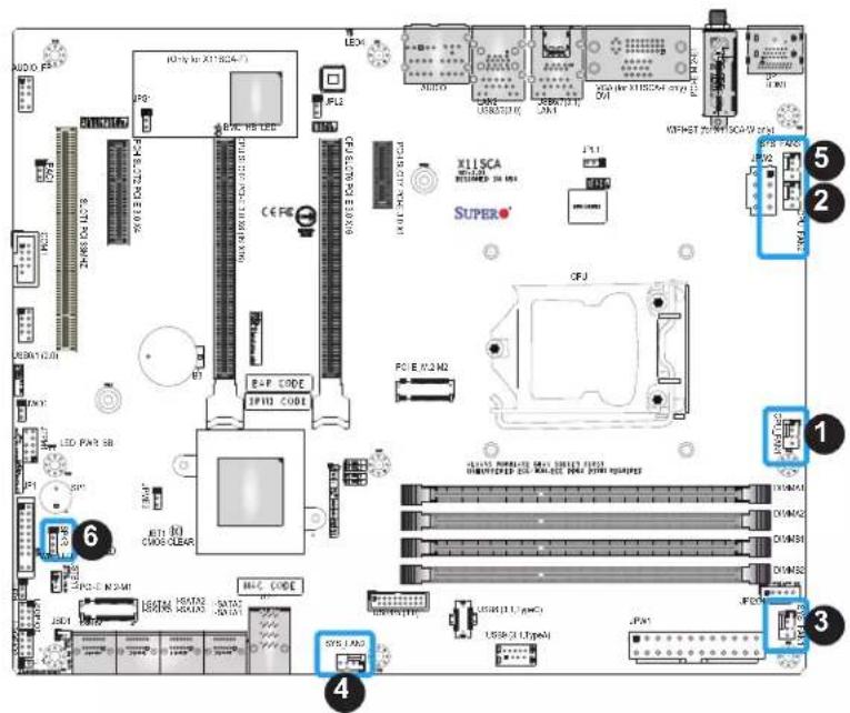
Fan Headers
The X11SCA/-W/-F has five fan headers (CPU_FAN1 \~ FAN2, SYS_FAN1 \~ FAN3). All of these 4-pin fan headers are backwards compatible with the traditional 3-pin fans. However, fan speed control is only available for 4-pin fans by Thermal Management via the IPMI 2.0 interface. Refer to the table below for pin definitions.
| Fan HeaderPin Definitions | |
| Pin# | Definition |
| 1 | Ground (Black) |
| 2 | 2.5A/+12V (Red) |
| 3 | Tachometer |
| 4 | PWM_Control |
Speaker/Buzzer Header
On the SPKR header, pins 1-4 are for the speaker and pins 3-4 are for the buzzer. If you wish to use an external speaker, connect its cable to pins 1-4.
| Speaker HeaderPin Definitions |
| Pin Setting Definition |
| Pins 1-4 Speaker |
| Pins 3-4 Buzzer |
text_image
AUDIO PS 100% 200% 300% 400% 500% 600% 700% 800% 900% 1000% LED PWR SB LED BIP LED BIP LED BIP LED BIP LED BIP LED BIP LED BIP LED BIP LED BIP LED BIP LED BIP LED BIP LED BIP LED BIP LED BIP LED BIP LED BIP LED BIP LED BIP LED BIP LED BIP LED BIP LED BIP LED BIP LED BIP LED BUP LED BUP LED BUP LED BUP LED BUP LED BUP LED BUP LED BUP LED BUP LED BUP LED BUP LED BUP LED BUP LED BUP LED BUP LED BUP LED BUP LED BUP LED BUP LED BUP LED BUP LED BUP LED BUP LED BUP LED BUP LED BOP LED BOP LED BOP LED BOP LED BOP LED BOP LED BOP LED BOP LED BOP LED BOP LED BOP LED BOP LED BOP LED BOP LED BOP LED BOP LED BOP LED BOP LED BOP LED BOP LED BOP LED BOP LED BOP LED BOP LED BOP LED BUP LED BUP LED BUP LED BUP LED BUP LED BUP LED BUP LED BUP LED BUP LED BUP LED BUP LED BUP LED BUP LED BUP LED BUP LED BUP LED BUP LED BUP LED BUP LED BUP LED BUP LED BUP LED BUP LED BUP LED B UP L1.1/1.2/1.3/1.4/1.5/1.6/1.7/1.8/1.9/2.0/2.1/2.2/2.3/2.4/2.5/2.6/2.7/2.8/2.9/3.0/3.1/3.2/3.3/3.4/3.5/3.6/3.7/3.8/3.9/4.0/4.1/4.2/4.3/4.4/4.5/4.6/4.7/4.8/4.9/5.0/5.1/5.2/5.3/5.4/5.5/5.6/5.7/5.8/5.9/6.0/6.1/6.2/6.3/6.4/6.5/6.6/6.7/6.8/6.9/7.0/7.1/7.2/7.3/7.4/7.5/7.6/7.7/7.8/7.9/8.0/8.1/8.2/8.3/8.4/8.5/8.6/8.7/8.8/8.9/9.0/9.1/9.2/9.3/9.4/9.5/9.6/9.7/9.8/9.9/10.0/ X11 SCA REQUINED IN MΩ SUPER® OFJ PC E W2 M2 17:1 17:1 17:1 17:1 17:1 17:1 17:1 17:1 17:1 17:1 17:1 17:1 17:1 17:1 17:1 17:1 17:1 17:1 17:1 17:1 17:2 17:2 17:2 17:2 17:2 17:2 17:2 17:2 17:2 17:2 17:2 17:2 17:2 17:2 17:2 17:2 17:2 17:2 17:2 17:2 17:3 17:3 17:3 17:3 17:3 17:3 17:3 17:3 17:3 17:3 17:3 17:3 17:3 17:3 17:3 17:3 17:3 17:3 17:3 17:3 17:2 17:2 17:2 17:2 17:2 17:2 17:2 17:2 17:2 17:2 17:2 17:2 17:2 17:2 17:2 17:2 17:2 17:2 17:2 17:4 17:4 17:4 17:4 17:4 17:4 17:4 17:4 17:4 17:4 17:4 17:4 17:4 17:4 17:4 17:4 17:4 17:4 17:4 17:4 17:3 17:3 17:3 17:3 17:3 17:3 17:3 17:3 17:3 17:3 17:3 17:3 17:3 17:3 17:3 16:4, LED PWR SB 600% COLD CLEAR 600% COLD CLEAR- CPU_FAN1
- CPU_FAN2
- SYS_FAN1
- SYS_FAN2
- SYS_FAN3
- Speaker/Buzzer Header
Internal Speaker/Buzzer
The Internal Speaker (SP1) can be used to provide audible notifications using various beep codes. Refer to the table below for pin definitions. Refer to the layout below for the location of the internal buzzer.
| Internal BuzzerPin Definitions | ||
| Pin# Definition | ||
| 1 Pos | (+) DC 5V | |
| 2 Neg | (-) Signal In | |

text_image
AUDIO PE 100% (in X11824-7) LED X115CA RECEIVED 30A SUPER® PCL E M/2 M2 OFJ LED PA2 SB 1 RESET CODE CLEAR HAC CODE USB(2.1 LpA) USB(2.1 LpA) LPG VREFST POWER SCA9 20A SPL PANS CPU C2 CPU CPU CPU CPU CPU CPU CPU CPU CPU CPU CPU CPU CPU CPU CPU CPU CPU CPU CPU CPU CPU CPU CPU CPU CPU CPU CPU CPU CPU CPU CPU CPU CPU CPU CPU CPU CPU CPU CPU CPU CPU CPU CPU CPU CPU CPU CPU CPU CPU CPU C2 C3 C4 C5 C6 C7 C8 C9 C10 C11 C12 C13 C14 C15 C16 C17 C18 C19 C20 C21 C22 C23 C24 C25 C26 C27 C28 C29 C30 C31 C32 C33 C34 C35 C36 C37 C38 C39 C40 C41 C42 C43 C44 C45 C46 C47 C48 C49 C50 C51 C52 C53 C54 C55 C56 C57 C58 C59 C60 C61 C62 C63 C64 C65 C66 C67 C68 C69 C70 C71 C72 C73 C74 C75 C76 C77 C78 C79 C80 C81 C82 C83 C84 C85 C86 C87 C88 C89 C90 C91 C92 C93 C94 C95 C96 C97 C98 C99 C100- Internal Speaker/Buzzer
SGPIO Headers
Two I-SGPIO (Serial Link General Purpose Input/Output) headers are located on the motherboard. They support the onboard I-SATA 3.0 ports. Refer to the tables below for pin definitions.
| I-SGPIO 1/2 |
| I-SGPIO1 I-SATA 3.0 Ports 0-3 |
| I-SGPIO2 I-SATA 3.0 Ports 4-7 |
| SGPIO HeaderPin Definitions | |||
| Pin# | Definition | Pin# | Definition |
| 1 NC | 2 NC | ||
| 3 GND | 4 Data | ||
| 5 Load | 6 GND | ||
| 7 Clock | 8 NC | ||
NC = No Connection

text_image
Labeled diagram of an electronic circuit board with component labels and connectors- I-SGPIO 1
- I-SGPIO 2
Standby Power
The +5V Standby Power header is located at JSTBY1 on the motherboard. You must have a card with a Standby Power connector and a cable to use this feature. Refer to the table below for pin definitions.
| Standby Power HeaderPin Definitions | |
| Pin# | Definition |
| 1 +5V | Standby |
| 2 Ground | |
| 3 NC | |
Disk On Module Power Connector
One power connector for SATA DOM (Disk On Module) device is located at JSD1. Connect appropriate cables here to provide power support for your Serial Link DOM devices.
| DOM Power Connector Pin Definitions | |
| Pin# Definition | |
| 1 5V | |
| 2 Ground | |
| 3 Ground | |
text_image
Circuit board layout diagram with labeled components and connectors, including CPU, memory, and peripheral modulesA Trusted Platform Module (TPM)/Port 80 header is located at JTPM1 to provide TPM support and a Port 80 connection. Use this header to enhance system performance and data security. Refer to the table below for pin definitions.
| Trusted Platform Module HeaderPin Definitions | ||
| Pin# Definition Pin# Definition | ||
| 1 VCC_3V3 2 CS | ||
| 3 RST 4 MISO | ||
| 5 CLK 6 GND | ||
| 7 MO$I 8 NC | ||
| 9 VCC_3V3SB 10 PIRQ | ||

text_image
Circuit board layout diagram with labeled components and connectors, including CPU, memory, and peripheral modules- TPM Header
M.2 Connections
The X11SCA/-W/-F contains three M.2 sockets, one of which supports WiFi, and bluetooth (pre-installed on the I/O back panel). M.2, formerly known as Next Generation Form Factor (NGFF), serves to replace mini PCI-E, and mSATA. M.2 allows for a greater variety of card sizes, increased functionality, and spatial efficiency. The M.2 M-key sockets support PCI-E 3.0 x4 (32 Gb/s) SSD cards in the 2280 form factor.

Note: If using an M.2 device with a lower thermal tolerance, a heatsink should be installed on top of the M.2 device, and the device should be set to "boot up device" (refer to Chapter 4).
Onboard Power LED Header
An onboard power LED header is located at JLED1. This power LED header is connected to the Front Control Panel located at JF1 to indicate the status of system power. Refer to the table below for pin definitions.
| Onboard Power LED Header Pin Definitions | |
| Pin# Definition | |
| 1 VCC | |
| 2 | Connection to PWRLED on JF1 |
| 3 | Connection to PWRLED on JF1 |

text_image
Labeled diagram of a computer motherboard showing component layouts and connectors, including CPU, memory, and peripheral modules.- M.2 M-key Socket (M.2-M1)
- M.2 M-key Socket (M.2-M2)
- M.2 E-key Socket (M.2-E1) (X11SCA-W only)
- Onboard Power LED Header
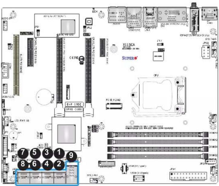
SATA and U.2 Ports
Eight SATA 3.0 ports, supported by the Intel C246 PCH chip, are located on this motherboard. These SATA ports support RAID 0, 1, 5, and 10. SATA ports provide serial-link signal connections, which are faster than the connections of Parallel ATA. Refer to the tables below for pin definitions.

Note: For more information on the SATA HostRAID configuration, please refer to the Intel SATA HostRAID user's guide posted on our website at http://www.supermicro.com.
| X11SCA/-W/-F SATA 3.0 Connector Types | |
| Port# Connection Type | |
| I-SATA 0-3(Four) | SATA 3.0/6 Gb/sRAID 0, 1, 5, 10 |
| I-SATA 4-7(Four) | SATA 3.0/6 Gb/sRAID 0, 1, 5, 10JSD1: SATA DOM connectors |
| Supported by Intel C246 PCH | |
| SATA 3.0 PortPin Definitions |
| Pin# Signal |
| 1 Ground |
| 2 SATA_TXP |
| 3 SATA_TXN |
| 4 Ground |
| 5 SATA_RXN |
| 6 SATA_RXP |
| 7 Ground |
text_image
AUDIO PS 100% for X11824-71 LED X11824 SIP 13 CE PE X11824 SUPERO OPJ POI E P/2 M2 LED PAR 5B 7 5 3 1 9 8 6 4 2 SYS LND USB (1.1 µCi) USB (2.1 µCi) JPAN- I-SATA0
- I-SATA1
- I-SATA2
- I-SATA3
- I-SATA4
- I-SATA5
- I-SATA6
- I-SATA7
- U.2-1
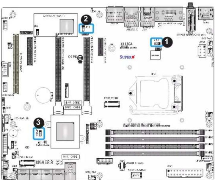
2.9 Jumper Settings
How Jumpers Work
To modify the operation of the motherboard, jumpers can be used to choose between optional settings. Jumpers create shorts between two pins to change the function of the connector. Pin 1 is identified with a square solder pad on the printed circuit board. Refer to the diagram below for an example of jumping pins 1 and 2. Refer to the motherboard layout page for jumper locations.

Note: On two-pin jumpers, "Closed" means the jumper is on and "Open" means the jumper is off the pins.

text_image
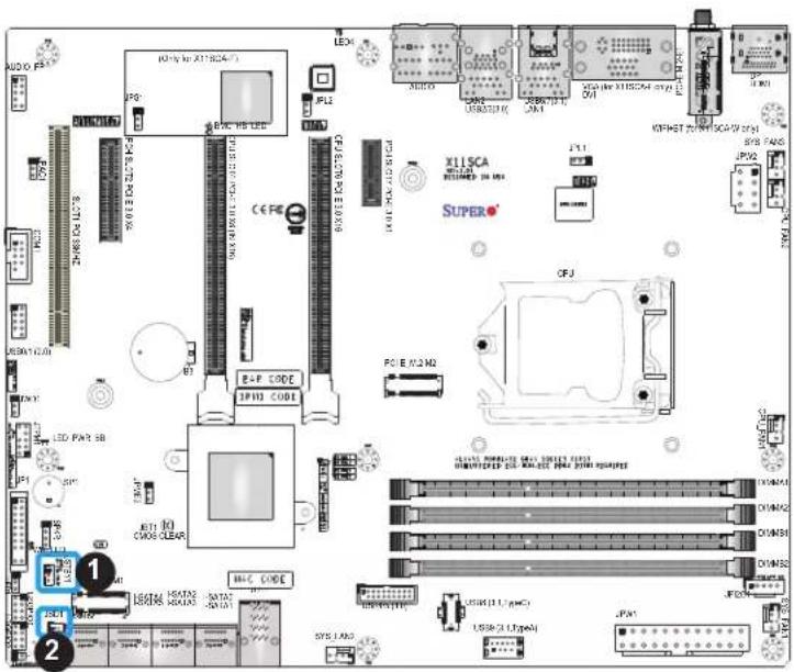
Connector Pins Jumper Setting 3 2 1 3 2 1CMOS Clear
JBT1 is used to clear the CMOS. Instead of pins, this jumper consists of contact pads to prevent accidental clearing of the CMOS. To clear the CMOS, use a metal object such as a small screwdriver to touch both pads at the same time to short the connection.

Note: Be sure to completely shut down the system, and then short JBT1 to clear the CMOS.
Watch Dog
Watch Dog (JWD1) is a system monitor that can reboot the system when a software application hangs. Close pins 1 and 2 to reset the system if an application hangs. Close pins 2 and 3 to generate a non-maskable interrupt (NMI) signal for the application that hangs. Refer to the table below for jumper settings. The Watch Dog must also be enabled in the BIOS. The default setting is Reset.
| Watch DogJumper Settings | |
| Jumper Setting Definition | |
| Pins 1-2 Reset | |
| Pins 2-3 NMI | |
| Open Disabled | |

text_image
AUDIO FF 10-12V to X11824- JP3 LED: USB LED CE FC X115CA REIMED IN MS SUPER® OFJ PO E M2 MD LED PAR 5B 1 ECI 10 CWOS CLEAR USB: HSDT2 USB: HSDT2 USB: HSDT2 USB: HSDT2 USB: HSDT2 USB: HSDT2 USB: HSDT2 USB: HSDT2 USB: HSDT2 USB: HSDT2 USB: HSDT2 USB: HSDT2 USB: HSDT2 USB: HSDT2 USB: HSDT2 SPLC LND JPN1 JPN2 JPN3 JPN4 JPN5 JPN6 JPN7 JPN8 JPN9 JPN10 JPN11 JPN12 JPN13 JPN14 JPN15 JPN16 JPN17 JPN18 JPN19 JPN20 JPN21 JPN22 JPN23 JPN24 JPN25 JPN26 JPN27 JPN28 JPN29 JPN30 JPN31 JPN32 JPN33 JPN34 JPN35 JPN36 JPN37 JPN38 JPN39 JPN40 JPN41 JPN42 JPN43 JPN44 JPN45 JPN46 JPN47 JPN48 JPN49 JPN50- CMOS Clear
- Watch Dog Timer
LAN Port Enable/Disable
Use JPL1 and JPL2 to enable or disable LAN ports 1 and 2 respectively on the motherboard. Refer to the table below for jumper settings. The default setting is Enabled.
| LAN1-LAN2 Enable/Disable Jumper Settings | |
| Jumper Setting Definition | |
| Pins 1-2 Enabled | |
| Pins 2-3 Disabled | |
Manufacturing Mode Select
Close pins 2 and 3 of JPME2 to bypass SPI flash security, and force the system to operate in the manufacturing mode, which will allow the user to flash the system firmware from a host server for system setting modifications. Refer to the table below for jumper settings. The default setting is Normal.
| Manufacturing ModeJumper Settings | |
| Jumper Setting Definition | |
| Pins 1-2 Normal | |
| Pins 2-3 | ManufacturingMode |
text_image
Labeled diagram of an electronic circuit board with component labels and pinouts- LAN1 Enable/Disable
- LAN2 Enable/Disable
- Manufacturing Mode
VGA Enable/Disable (X11SCA-F Only)
JPG1 allows the user to enable the onboard VGA connector. The default setting is pins 1 and 2 to enable the connection. Refer to the table below for jumper settings.
| VGA Enable/DisableJumper Settings |
| Jumper Setting Definition |
| Pins 1-2 Enabled |
| Pins 2-3 Disabled |
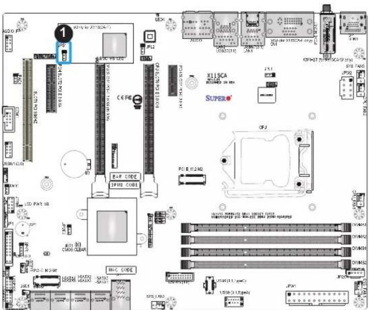
text_image
Circuit board layout diagram with labeled components including CPU, memory, and peripheral modules- VGA Enable
2.10 LED Indicators
LAN LEDs
Two LAN ports (LAN1/LAN2) are located on the I/O back panel of the motherboard. Each Ethernet LAN port has two LEDs. The green LED indicates activity, while the other Link LED may be green, amber, or off to indicate the speed of the connection. Refer to the tables below for more information.
| LAN1/2 Activity LEDs (Right)LED State | |
| Color Status Definition | |
| Green Flashing Active | |
| LAN1/2 Link LEDs (Left)LED State | |
| LED Color Definition | |
| Off No Connection | |
| Amber 10 Mbps/100 Mbps | |
| Green 1 Gbps |
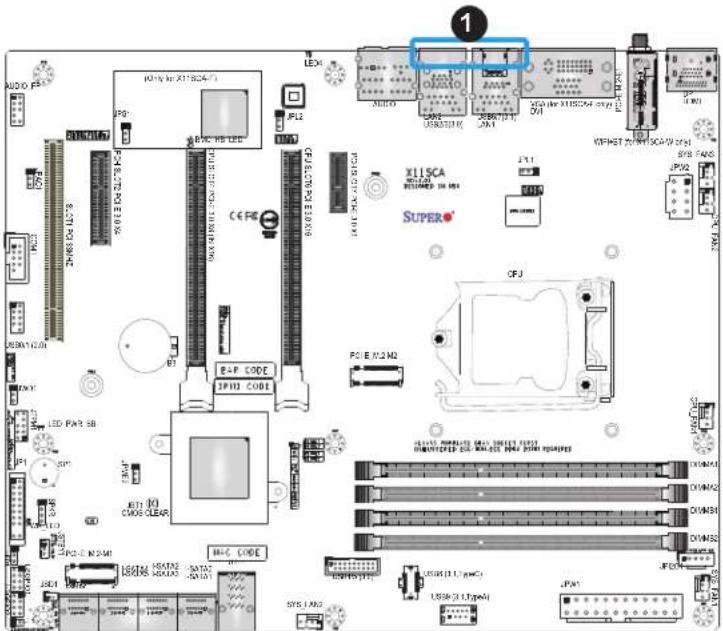
text_image
AUDIO PE 100% (vs X11SC4-7) LED X11SCA RESUMED 35.0kV SUPER® R-F CODE IP102 CODE PCI E M2 M2 OFF LED PAP SB LED PAP SB LED PAP SB LED PAP SB LED PAP SB LED PAP SB LED PAP SB LED PAP SB LED PAP SB LED PAP SB LED PAP SB LED PAP SB LED PAP SB LED PAP SB LED PAP SB LED PAP SB LED PAP SB LED PAP SB LED PAP SB LED PAP SB LED PAP BB LED PAP BB LED PAP BB LED PAP BB LED PAP BB LED PAP BB LED PAP BB LED PAP BB LED PAP BB LED PAP BB LED PAP BB LED PAP BB LED PAP BB LED PAP BB LED PAP BB LED PAP BB LED PAP BB LED PAP BB LED PAP BB LED PAP BB LED PAP B LED PAP B LED PAP B LED PAP B LED PAP B LED PAP B LED PAP B LED PAP B LED PAP B LED PAP B LED PAP B LED PAP B LED PAP B LED PAP B LED PAP B LED PAP B LED PAP B LED PAP B LED PAP B LED PAP B LED PAP BB LED PAP BB LED PAP BB LED PAP BB LED PAP BB LED PAP BB LED PAP BB LED PAP BB LED PAP BB LED PAP BB LED PAP BB LED PAP BB LED PAP BB LED PAP BB LED PAP BB LED PAP BB LED PAP BB LED PAP BB LED PAP BB LED PAP PP LED PAP PP LED PAP PP LED PAP PP LED PAP PP LED PAP PP LED PAP PP LED PAP PP LED PAP PP LED PAP PP LED PAP PP LED PAP PP LED PAP PP LED PAP PP LED PAP PP LED PAP PP LED PAP PP LED PAP PP LED PAP PP LED PAP PP LED PAP BB LED PAP BB LED PAP BB LED PAP BB LED PAP BB LED PAP BB LED PAP BB LED PAP BB LED PAP BB LED PAP BB LED PAP BB LED PAP BB LED PAP BB LED PAP BB LED PAP BB LED PAP BB LED PAP BB- LAN1/LAN2 LEDs
Standby Power LED
The Standby Power LED indicator is located at LED_PWR_SB on the motherboard. When this LED is on, the system is receiving power. Be sure to turn off the system and unplug the power cord before removing or installing components. Refer to the table below for more information.
| Standby Power LED Indicator | |
| LED Color Definition | |
| Off | Standby Power Off(power cable not connected) |
| Green Standby Power On | |
Power LED
PWR_LED is the power LED indicator. When this LED is lit, it means power is present on the motherboard. In suspend mode, this LED will blink on and off. Be sure to turn off the system and unplug the power cord(s) before removing or installing components.
| Onboard Power LED Indicator | |
| LED Color Definition | |
| Off | System Off(power cable not connected) |
| Green System | On |
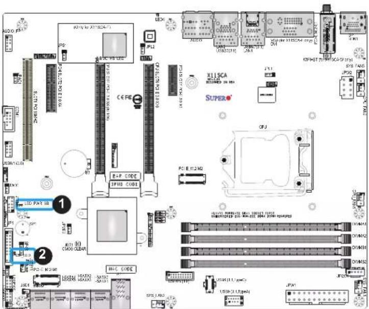
text_image
Labeled diagram of an electronic circuit board with component labels and pinouts, including CPU, memory, and control modules.- Standby PWR LED
- Power LED
UID LED Indicator (X11SCA-F only)
The UID LED is located at LED4. The LED indicator provides easy identification of a system unit that may be in need of service.
| UID LED Indicator | |
| Color Status | |
| Blue: On Unit Identified |
BMC Heartbeat LED (X11SCA-F only)
BMC_HB_LED is the BMC heartbeat LED indicator. When the LED is blinking green, BMC is functioning normally. Refer to the table below for the LED status.
| BMC Heartbeat LED Indicator |
| LED Color Definition |
| Blinking Green BMC Normal |
text_image
1 LED4 2 XILSCA RESERVED 30.000 SUPER® CPU E/O 2.0Ω OFF LED PWR SB LED PWR SB LED PWR SB LED PWR SB LED PWR SB LED PWR SB LED PWR SB LED PWR SB LED PWR SB LED PWR SB LED PWR SB LED PWR SB LED PWR SB LED PWR SB LED PWR SB LED PWR SB LED PWR SB LED PWR SB LED PWR SB LED PWR SB LED PWR DB LED PWR DB LED PWR DB LED PWR DB LED PWR DB LED PWR DB LED PWR DB LED PWR DB LED PWR DB LED PWR DB LED PWR DB LED PWR DB LED PWR DB LED PWR DB LED PWR DB LED PWR DB LED PWR DB LED PWR DB LED PWR DB LED PWR DB LED PWR D1.1μmC1 LED PWR D1.1μmC1 LED PWR D1.1μmC1 LED PWR D1.1μmC1 LED PWR D1.1μmC1 LED PWR D1.1μmC1 LED PWR D1.1μmC1 LED PWR D1.1μmC1 LED PWR D1.1μmC1 LED PWP D1.1μmC1 LED PWP D1.1μmC1 LED PWP D1.1μmC1 LED PWP D1.1μmC1 LED PWP D1.1μmC1 LED PWP D1.1μmC1 LED PWP D1.1μmC1 LED PWP D1.1μmC1 LED PWP D1.2μmC1 LED PWP D1.2μmC1 LED PWP D1.2μmC1 LED PWP D1.2μmC1 LED PWP D1.2μmC1 LED PWP D1.2μmC1 LED PWP D1.2μmC1 LED PWP D2.2μmC1 LED PWP D2.2μmC1 LED PWP D2.2μmC1 LED PWP D2.2μmC1 LED PWP D2.2μmC1 LED PWP D2.2μmC1 LED PWP D2.2μmC1 LED PWP D2.2μmC1 LED PWP D2.2μMnS LED PWP D2.2μMnS LED PWP D2.2μMnS LED PWP D2.2μMnS LED PWP D2.2μMnS LED PWP D2.2μMnS LED PWP D2.2μMnS LED PWP D2.2μMnS LED PWP D2.2μMnS LED PWT D2.2μMnS LED PWT D2.2μMnS LED PWT D2.2μMnS LED PWT D2.2μMnS LED PWT D2.2μMnS LED PWT D2.2μMnS- UID LED
- BMC Heartbeat LED
Chapter 3
Troubleshooting
3.1 Troubleshooting Procedures
Use the following procedures to troubleshoot your system. If you have followed all of the procedures below and still need assistance, refer to the 'Technical Support Procedures' and/or 'Returning Merchandise for Service' section(s) in this chapter. Always disconnect the AC power cord before adding, changing or installing any non hot-swap hardware components.
Before Power On
- Make sure that there are no short circuits between the motherboard and chassis.
- Disconnect all ribbon/wire cables from the motherboard, including those for the keyboard and mouse.
- Remove all add-on cards.
- Install the CPU (making sure it is fully seated) and connect the front panel connectors to the motherboard.
No Power
- Make sure that there are no short circuits between the motherboard and the chassis.
- Make sure that the ATX power connectors are properly connected.
- Check that the 115V/230V switch, if available, on the power supply is properly set.
- Turn the power switch on and off to test the system, if applicable.
- The battery on your motherboard may be old. Check to verify that it still supplies \~3VDC. If it does not, replace it with a new one.
No Video
- If the power is on but you have no video, remove all add-on cards and cables.
-
Use the speaker to determine if any beep codes are present. Refer to Appendix A for details on beep codes.
-
Remove all memory modules and turn on the system (if the alarm is on, check the specs of memory modules, reset the memory or try a different one).
System Boot Failure
If the system does not display POST or does not respond after the power is turned on, check the following:
- Check for any error beep from the motherboard speaker.
- If there is no error beep, try to turn on the system without DIMM modules installed. If there is still no error beep, replace the motherboard.
- If there are error beeps, clear the CMOS settings by unplugging the power cord and contacting both pads on the CMOS clear jumper (JBT1). (Refer to Section 2.9.)
- Remove all components from the motherboard, especially the DIMM modules. Make sure that system power is on and that memory error beeps are activated.
- Turn on the system with only one DIMM module installed. If the system boots, check for bad DIMM modules or slots by following the Memory Errors Troubleshooting procedure in this chapter.
Memory Errors
When a no-memory beep code is issued by the system, check the following:
-
Make sure that the memory modules are compatible with the system and that the DIMMs are properly and fully installed. (For memory compatibility, refer to the memory compatibility chart posted on our website at http://www.supermicro.com.)
-
Check if different speeds of DIMMs have been installed. It is strongly recommended that you use the same RAM type and speed for all DIMMs in the system.
-
Make sure that you are using the correct type of ECC DDR4 UDIMM modules recommended by the manufacturer.
-
Check for bad DIMM modules or slots by swapping a single module among all memory slots and check the results.
-
Make sure that all memory modules are fully seated in their slots. Follow the instructions given in Section 2.4.
-
Please follow the instructions given in the DIMM population tables listed in Section 2.4 to install your memory modules.
Losing the System's Setup Configuration
- Make sure that you are using a high-quality power supply. A poor-quality power supply may cause the system to lose the CMOS setup information. Refer to Section 2.8 for details on recommended power supplies.
- The battery on your motherboard may be old. Check to verify that it still supplies \~3VDC. If it does not, replace it with a new one. If the above steps do not fix the setup configuration problem, contact your vendor for repairs.
When the System Becomes Unstable
A. If the system becomes unstable during or after OS installation, check the following:
- CPU/BIOS support: Make sure that your CPU is supported and that you have the latest BIOS installed in your system.
- Memory support: Make sure that the memory modules are supported by testing the modules using memtest86 or a similar utility.

Note: Refer to the product page on our website at http://www.supermicro.com for memory and CPU support and updates.
- HDD support: Make sure that all hard disk drives (HDDs) work properly. Replace the bad HDDs with good ones.
- System cooling: Check the system cooling to make sure that all heatsink fans and CPU/system fans, etc., work properly. Check the hardware monitoring settings in the IPMI to make sure that the CPU and system temperatures are within the normal range. Also check the front panel Overheat LED and make sure that it is not on.
- Adequate power supply: Make sure that the power supply provides adequate power to the system. Make sure that all power connectors are connected. Please refer to our website for more information on the minimum power requirements.
- Proper software support: Make sure that the correct drivers are used.
B. If the system becomes unstable before or during OS installation, check the following:
- Source of installation: Make sure that the devices used for installation are working properly, including boot devices such as CD/DVD.
-
Cable connection: Check to make sure that all cables are connected and working properly.
-
Using the minimum configuration for troubleshooting: Remove all unnecessary components (starting with add-on cards first), and use the minimum configuration (but with the CPU and a memory module installed) to identify the trouble areas. Refer to the steps listed in Section A above for proper troubleshooting procedures.
- Identifying bad components by isolating them: If necessary, remove a component in question from the chassis, and test it in isolation to make sure that it works properly. Replace a bad component with a good one.
- Check and change one component at a time instead of changing several items at the same time. This will help isolate and identify the problem.
- To find out if a component is good, swap this component with a new one to see if the system will work properly. If so, then the old component is bad. You can also install the component in question in another system. If the new system works, the component is good and the old system has problems.
3.2 Technical Support Procedures
Before contacting Technical Support, please take the following steps. Also, please note that as a motherboard manufacturer, Supermicro also sells motherboards through its channels, so it is best to first check with your distributor or reseller for troubleshooting services. They should know of any possible problems with the specific system configuration that was sold to you.
- Please go through the Troubleshooting Procedures and Frequently Asked Questions (FAQ) sections in this chapter or see the FAQs on our website (http://www.supermicro.com/) before contacting Technical Support.
- BIOS upgrades can be downloaded from our website http://www.supermicro.com/ResourceApps/BIOS_IPMI_Intel.html.
-
If you still cannot resolve the problem, include the following information when contacting Supermicro for technical support:
-
Motherboard model and PCB revision number
- BIOS release date/version (This can be seen on the initial display when your system first boots up.)
-
System configuration
-
An example of a Technical Support form is on our website at http://www.supermicro.com/RmaForm/.
- Distributors: For immediate assistance, please have your account number ready when placing a call to our Technical Support department. We can be reached by email at support@supermicro.com.
3.3 Frequently Asked Questions
Question: What type of memory does my motherboard support?
Answer: The motherboard supports ECC DDR4 UDIMM modules. To enhance memory performance, do not mix memory modules of different speeds and sizes. Please follow all memory installation instructions given in Section 2.4 Memory Support and Installation.
Question: How do I update my BIOS?
Answer: It is recommended that you do not upgrade your BIOS if you are not experiencing any problems with your system. Updated BIOS files are located on our website at http://www.supermicro.com/ResourceApps/BIOS_IPMI_Intel.html. Please check our BIOS warning message and the information on how to update your BIOS on our website. Select your motherboard model and download the BIOS file to your computer. Also, check the current BIOS revision to make sure that it is newer than your BIOS before downloading. To update your BIOS under the UEFI shell, please unzip the BIOS file onto a USB device formatted with the FAT/FAT32 file system. When the UEFI shell prompt appears, type fs# to change the device directory path. Go to the directory that contains the BIOS package you extracted earlier. Enter flash.nsh BIOSname#.### at the prompt to start the BIOS update process. Reboot the system when you see the message that BIOS update has completed. Refer to the readme file for more information.
Warning: Do not shut down or reset the system while updating the BIOS to prevent possible system boot failure!

Note: The SPI BIOS chip used on this motherboard cannot be removed. Send your motherboard back to our RMA Department at Supermicro for repair. For BIOS Recovery instructions, please refer to the AMI BIOS Recovery Instructions posted at http://www.supermicro.com.
3.4 Battery Removal and Installation
Battery Removal
To remove the onboard battery, follow the steps below:
- Power off your system and unplug your power cable.
- Locate the onboard battery as shown below.
- Using a tool such as a pen or a small screwdriver, push the battery lock outwards to unlock it. Once unlocked, the battery will pop out from the holder.
- Remove the battery.
Proper Battery Disposal
Please handle used batteries carefully. Do not damage the battery in any way; a damaged battery may release hazardous materials into the environment. Do not discard a used battery in the garbage or a public landfill. Please comply with the regulations set up by your local hazardous waste management agency to dispose of your used battery properly.
Battery Installation
- To install an onboard battery, follow the steps 1 and 2 above and continue below:
- Identify the battery's polarity. The positive (+) side should be facing up.
- Insert the battery into the battery holder and push it down until you hear a click to ensure that the battery is securely locked.

Important: When replacing a battery, be sure to only replace it with the same type.

text_image
LITHIUM BATTERY BATTERY HOLDER3.5 Returning Merchandise for Service
A receipt or copy of your invoice marked with the date of purchase is required before any warranty service will be rendered. You can obtain service by calling your vendor for a Returned Merchandise Authorization (RMA) number. When returning to the manufacturer, the RMA number should be prominently displayed on the outside of the shipping carton and mailed prepaid or hand-carried. Shipping and handling charges will be applied for all orders that must be mailed when service is complete.
For faster service, RMA authorizations may be requested online (http://www.supermicro.com/support/rma/).
This warranty only covers normal consumer use and does not cover damages incurred in shipping or from failure due to the alteration, misuse, abuse or improper maintenance of products.
During the warranty period, contact your distributor first for any product problems.
Chapter 4
UEFI BIOS
4.1 Introduction
This chapter describes the AMIBIOS™ Setup utility for the X11SCA/-W/-F motherboard. The BIOS is stored on a chip and can be easily upgraded using a flash program.

Note: Due to periodic changes to the BIOS, some settings may have been added or deleted and might not yet be recorded in this manual. Please refer to the Manual Download area of our website for any changes to the BIOS that may not be reflected in this manual.
Starting the Setup Utility
To enter the BIOS Setup Utility, hit the
The Main BIOS screen has three main frames. The upper frame displays the time and date, as well as motherboard information (model, BIOS data, CPU data, and memory data). The left frame displays all the features that can be configured. "Grayed-out" features cannot be configured. The right frame displays the key legend. Above the key legend is an area reserved for a text message. When an option is selected in the left frame, it is highlighted in blue. Often a text message will accompany it. (Note that BIOS has default text messages built in. We retain the option to include, omit, or change any of these text messages.) Settings printed in Bold are the default values.
A "▶" indicates a submenu. Highlighting such an item and pressing the
The BIOS Setup utility uses a key-based navigation system called hot keys. Most of these hot keys (
4.2 Main
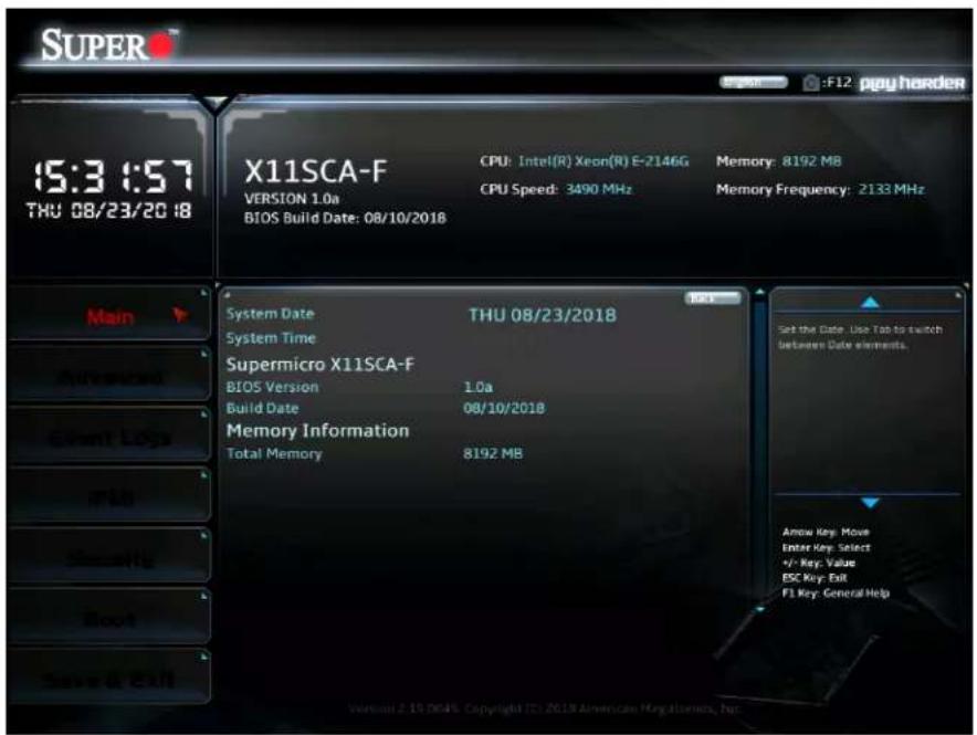
text_image
SUPER 15:3:57 THU 08/23/2018 X11SCA-F CPU: Intel(R) Xeon(R) E-2146G Memory: 8192 MB VERSION 1.0a CPU Speed: 3490 MHz Memory Frequency: 2133 MHz BIOS Build Date: 08/10/2018 System Date THU 08/23/2018 System Time Supermicro X11SCA-F BIOS Version 1.0a Build Date 08/10/2018 Memory Information Total Memory 8192 MB Set the Date. Use Tab to switch between Data elements. Arrow Key: Move Enter Key: Select +/- Key: Value ESC Key: Exit F1 Key: General Help Version 2.15.004% Copyright ID: 2018 American Magellanos, Inc.The following information is displayed in this section:
- System Date - the date the system is set to
• System Time - the time the system is set to - Motherboard Model - the model of the motherboard
• BIOS Version - the current BIOS version
• Build Date - the date the BIOS version was released
• Total Memory - the total memory installed on the system
4.3 Advanced

Warning: Take caution when changing the Advanced settings. An incorrect value, a very high frequency, or an incorrect timing setting may make the system unstable. If this occurs, revert to the default to the manufacture default settings.
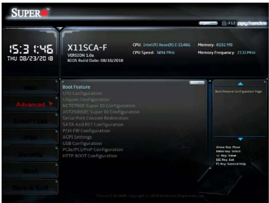
text_image
SUPER 15:3 0:46 THU 08/23/20 18 X11SCA-F VERSION 1.0a BIOS Build Date: 08/10/2018 CPU: Intel(R) Xeon(R) E-2146G CPU Speed: 3494 MHz Memory: 8192 MB Memory Frequency: 2133 MHz Boot Feature CPU Configuration Chipset Configuration NCT6796D Super IO Configuration AST2500SEC Super IO Configuration Serial Port Console Redirection SATA And RST Configuration PCH-FW Configuration ACPI Settings USB Configuration PCIe/PCI/PnP Configuration HTTP BOOT Configuration Boot Feature Configuration Page Arrow Key: Move Enter Key: Select +/- Key: Value ESC Key: Exit F1 Key: General Help Version 2.15.084% Copyright (C) 2018 American Macromedia, Net▶Boot Feature
Fast Boot
This feature enables the system to boot with a minimal set of required devices to launch. This has no effect on BBS boot options. The options are Disabled and Enabled.
Quiet Boot
Use this feature to select the screen display between the POST messages and the OEM logo upon bootup. Uncheck the box to display the POST messages. Check the box to display the OEM logo instead of the normal POST messages. The default is Checked.
Bootup NumLock State
Use this feature to set the Power-on state for the
Option ROM Messages
This feature controls the display mode for Option ROM. The options are Force BIOS and Keep Current.
Wait For "F1" If Error
Use this feature to force the system to wait until the "F1" key is pressed if an error occurs. The options are Disabled and Enabled.
Re-try Boot
If this feature is enabled, the BIOS will automatically reboot the system from a specified boot device after its initial boot failure. The options are Disabled, Legacy Boot, and EFI Boot.
Watch Dog Function
If enabled, the Watch Dog Timer will allow the system to reset or generate NMI based on jumper settings when it is expired for more than five minutes. The options are Disabled and Enabled.
AC Loss Policy Depend on
Use this feature to set the power state after a power outage. Select Stay Off for the system power to remain off after a power loss. Select Power On for the system power to be turned on after a power loss. Select Last State to allow the system to resume its last power state before a power loss. The options are Stay Off, Power On, and Last State.
Power Button Function
This feature controls how the system shuts down when the power button is pressed. Select 4 Seconds Override for the user to power off the system after pressing and holding the power button for four seconds or longer. Select Instant Off to instantly power off the system as soon as the user presses the power button. The options are Instant Off and 4 Seconds Override.
DeepSx Power Policies
Use this feature to configure the Advanced Configuration and Power Interface (ACPI) settings for the system. Enable S5 to power off the whole system except the power supply unit (PSU) and keep the power button alive so that the user can wake up the system by using an USB keyboard or mouse. The options are Disabled and Enabled in S4-S5.
Install Windows 7 USB Support
Enable this feature to use the USB keyboard and mouse during the Windows 7 installation, since the native XHCI driver support is unavailable. Use a SATA optical drive as a USB drive, and USB CD/DVD drives are not supported. Disable this feature after the XHCI driver has been installed in Windows. The options are Disabled and Enabled.
▶CPU Configuration
The following information is displayed in this section:
• CPU Signature - the processor identification code
- Microcode Patch - the microcode revision number
• MAX CPU Speed - the maximum CPU speed
- Min CPU Speed - the minimum CPU speed
• CPU Speed - the approximate CPU speed - Processor Cores - the number of processor cores
• Hyper Threading Technology - displays whether hyper threading is supported - VMX - displays whether VMX is supported
- SMX/TXT - displays whether SMX/TXT is supported
- 64-bit - displays whether 64-bit technology is supported
- EIST Technology - displays whether EIST technology is supported
• CPU C3 state - displays whether CPU C3 is supported
• CPU C6 state - displays whether CPU C6 is supported
• CPU C7 state - displays whether CPU C7 is supported
• CPU C8 state - displays whether CPU C8 is supported
• CPU C9 state - displays whether CPU C9 is supported
• CPU C10 state - displays whether CPU C10 is supported - L1 Data Cache - the size of the L1 data cache (if supported)
- L1 Instruction Cache - the size of the L1 instruction cache (if supported)
• L2 Cache - the size of the L2 cache (if supported)
• L3 Cache - the size of the L3 cache (if supported)
• L4 Cache - the size of the L4 cache (if supported)
C6DRAM
This feature enables moving DRAM contents to PRM memory when the CPU is in a C6 state. The options are Disabled and Enabled.
Hardware Prefetcher
If set to Enabled, the hardware prefetcher will prefetch streams of data and instructions from the main memory to the L2 cache to improve CPU performance. The options are Disabled and Enabled.
Adjacent Cache Line Prefetch
Select Enabled for the CPU to prefetch both cache lines for 128 bytes as comprised. Select Disabled for the CPU to prefetch both cache lines for 64 bytes. The options are Disabled and Enabled.
Intel (VMX) Virtualization Technology
Select Enabled to use the Intel Virtualization Technology to allow one platform to run multiple operating systems and applications in independent partitions, creating multiple "virtual" systems in one physicalcomputer. The options are Disabled and Enabled.

Note: If there is any change to this setting, you will need to power off and reboot the system for the change to take effect. Please refer to Intel's website for detailed information.
Active Processor Cores
Use this feature to select the number of active processor cores. The options depend on how many cores are supported by the CPU (up to 8). The default is All.
Hyper-Threading
This feature should be enabled for Windows XP and Linux. This feature should be disabled for other operating systems, as they are not optimized for Hyper-Threading. The default is Enabled.
AES
This feature enables Intel CPU Advanced Encryption Standard (AES) Instructions support to enhance data integrity. The options are Disabled and Enabled.
Boot Performance Mode
This feature enables the selection of the default CPU performance during system boot. The options are Max Non-Turbo Performance, Power Saving, and Turbo Performance.
Intel(R) SpeedStep(tm)
Intel SpeedStep Technology allows the system to automatically adjust processor voltage and core frequency in an effort to reduce power consumption and heat dissipation. Please refer to Intel's website for detailed information. The options are Disabled and Enabled.
Intel(R) Speed Shift Technology
This feature enables Intel® Speed Shift Technology support, which exposes the CPPC v2 interface to allow for hardware controlled P-States. The options are Disabled and Enabled.
Turbo Mode
This feature enables Turbo Mode if EMTTM is also enabled. The options are Disabled and Enabled.
Package Power Limit MSR Lock
This feature enables Package Power Limit locking. If this is enabled, a reset will be required to unlock the register. The options are Disabled and Enabled.
Power Limit 1 Override
This feature enables Power Limit 1 override. When this is disabled, the BIOS will use default values. The default is Disabled.
Power Limit 2 Override
This feature enables Power Limit 2 override. When this is disabled, the BIOS will use default values. The default is Enabled.
Power Limit 2
Enter a value for Power Limit 2. The default is 0.
1-core \~ 6-core Ratio Limit Override
The number of cores available to modify depends on the CPU installed. Enter a ratio limit value for individual cores.
C states
C-State architecture, a processor power management platform developed by Intel, can further reduce power consumption from the basic C1 (Halt State) state that blocks clock cycles to the CPU. Select Enabled for CPU C-State support. The options are Disabled and Enabled. If this feature is set to Enabled, the following features will display:
Enhanced C-states
This feature enables Enhanced C1 Power State to boost system performance. The options are Disabled and Enabled.
C-State Auto Demotion
When this feature is enabled, the CPU will conditionally demote C State based on un-cored auto-demote information. The options are Disabled, C1, C3, and C1 and C3.
C-State Un-demotion
When this feature is enabled, the CPU will conditionally undemote from demoted C1 or C3. The options are Disabled, C1, C3, and C1 and C3.
Package C-State Demotion
This feature enables the Package C-State demotion. The options are Disabled and Enabled.
Package C-State Un-demotion
When this feature is enabled, the CPU will conditionally undemote from demoted Packaged Package C-State Un-Demotion. The options are Disabled and Enabled.
CState Pre-Wake
Use this feature to enable the C-State pre wake. The options are Disabled and Enabled.
Package C State Limit
Select Auto for the AMI BIOS to automatically set the limit on the C-State package register. The options are C0/C1, C2, C3, C6, C7, C7s, C8, C9, C10, CPU Default, and Auto.
▶Chipset Configuration
▶System Agent (SA) Configuration
• SA PCIe Code Version
- VT-d
▶ Memory Configuration
The following information is displayed:
• Memory RC Version
• Memory Frequency
• Memory Timings (tCL-tRCD-tRP-tRAS)
• DIMMA1 \~ DIMMB2 information
Maximum Memory Frequency
This feature selects the type/speed of the memory installed. The options are Auto, 1067, 1333, 1400, 1600, 1867, 2133, 2200, 2400, 2600, and 2667. All values are in MHz.
Max TOLUD
This feature sets the maximum TOLUD value, which specifies the "Top of Low Usable DRAM" memory space to be used by internal graphics devices, GTT Stolen Memory, and TSEG, respectively, if these devices are enabled. The options are Dynamic, 1 GB \~ 3.5 GB (in increments of 0.25 GB).
Memory Scrambler
This feature enables memory scrambler support for memory error correction. The options are Disabled and Enabled.
MRC Fast Boot
Use this feature to enable or disable fast path through the memory reference code. The options are Disabled and Enabled.
▶ Graphics Configuration
- IGFX VBIOS Version
- IGFX GOP Version
Primary Display
This feature controls which graphics device will be used as the primary display. The options are Auto, IGFX, PEG, PCI, and SG.
Primary PEG
This feature controls the graphics device to be used as the primary device. The options are CPU SLOT6 PCI-E 3.0 X16 and CPU SLOT4 PCI-E 3.0 X8 (IN X16).
Primary PCIE
This feature controls the primary PCIE device. The options are Auto, OnBoard, PCH SLOT2 PCI-E 3.0 X4, and PCH SLOT7 PCI-E 3.0 X1.
Internal Graphics
This feature enables internal graphics support, based on the setup options. The options are Auto, Disabled, and Enabled.
GTT Size
This feature controls the memory allocation size for the graphics translation table (GTT). The options are 2MB, 4MB, and 8MB.
Aperture Size
This feature controls the graphics aperture size. For optimal performance, select the size that matches the installed graphics card's size. The options are 128MB, 256MB, 512MB, 1024MB, and 2048MB.
DVMT Pre-Allocated
This feature controls the DVMT 5.0 Pre-allocated graphics memory size to be used by the internal graphics device. The options are 0M, 32M, 64M, 4M, 8M, 12M, 16M, 20M, 24M, 28M, 36M, 40M, 44M, 48M, 52M, 56M, and 60M.
DVMT Total Gfx Mem
This feature controls the DVMT 5.0 total graphics size to be used by the internal graphics device. The options are 128M, 256M, and MAX.
VDD Enable
This feature enables VDD in the BIOS. The options are Disabled and Enabled.
PM Support
Enable this feature to activate Power Management BIOS support. The options are Enable and Disable.
PAVP Enable
Protected Audio Video Path (PAVP) decodes Intel integrated graphics encrypted video. The options are Enable and Disable.
Cdynmax Clamping Enable
This feature enables Cdynmax Clamping. The options are Enable and Disable.
Graphics Clock Frequency
This feature controls the graphics clock frequency. Select the highest clock frequency supported by the platform. The options are 337.5 MHz, 450 MHz, 540 MHz, and 675 MHz.
Skip CD Clock Init in S3 resume
When this feature is enabled, the system will skip full CD clock initialization during S3 Resume. The options are Enable and Disable.
▶DMI/OPI Configuration
DMI
This feature displays the DMI link and speed information.
DMI Link ASPM Control
This feature enables the control of Active State Power Management (ASPM) on the SA side of the DMI Link. The options are Disabled and L0sL1.
DMI Extended Sync Control
This feature enables DMI Extended Synchronization support. The options are Disabled and Enabled.
DMI De-emphasis Control
This feature controls the DMI De-emphasis setting. The options are -6 dB and -3.5 dB.
▶PEG Port Configuration
CPU SLOT6 PCI-E 3.0 X16
This displays information if a PCI-E device is installed.
SLOT6 Max Link Speed
Select Auto, Gen1, Gen2, or Gen3 to set the PEG Max Link Speed.
SLOT6 Power Limit Value
Enter a value for the upper limit on power (in watts) supplied by the slot. The range is 0-255. The default is 75.
SLOT6 Power Limit Scale
This feature controls the slot power limit scale. The options are 1.0x, 0.1x, 0.01x, and 0.001x.
CPU SLOT4 PCI-E 3.0 X8 (IN X16)
This displays information if a PCI-E device is installed.
SLOT4 Max Link Speed
Select Auto, Gen1, Gen2, or Gen3 to set the PEG Max Link Speed.
SLOT4 Power Limit Value
Enter a value for the upper limit on power (in watts) supplied by the slot. The range is 0-255. The default is 75.
SLOT4 Power Limit Scale
This feature controls the slot power limit scale. The options are 1.0x, 0.1x, 0.01x, and 0.001x.
ASPM
Use this feature to activate the Active State Power Management (ASPM) level for a PCI-E device. Select Auto for the system BIOS to automatically set the ASPM level based on the system configuration. Select Disabled to disable ASPM support. The options are Disable, Auto, ASPM L0s, ASPM L1, and ASPM L0sL1.
Program PCIe ASPM after OpROM
This feature enables PCIe ASPM programming after OpROM. If set to Disabled, programming occurs before OpROM. The options are Disabled and Enabled.
▶GT - Power Management Control
RC6(Render Standby)
Use this feature to enable Render Standby support. The options are Disabled and Enabled.
Maximum GT frequency
This feature defines the Maximum GT Frequency. Choose between 300MHz (RPN) and 1200MHz (RP0). Any value beyond this range will be clipped to its min/max supported by the CPU. The options are Default Max Frequency and 300MHz\~1200MHz (in increments of 50MHz).
Disable Turbo GT frequency
This feature disables Turbo GT frequency. Selecting Enabled disables Turbo GT frequency. If set to Disabled, GT frequency limiters will be removed. The default is Disabled.
VT-d
Select Enabled to activate Intel Virtualization Technology support for Direct I/O VT-d by reporting the I/O device assignments to VMM through the DMAR ACPI Tables. This feature offers fully-protected I/O resource-sharing across the Intel platforms, providing the user with greater reliability, security and availability in networking and data-sharing. The options are Disable and Enable.
SW Guard Extensions (SGX)
Select Enabled to activate the Software Guard Extensions (SGX). The options are Disabled, Enabled, and Software Controlled.
Select Owner EPOCH input type
There are three Owner EPOCH modes (each EPOCH is 64 bit). The options are No Change in Owner EPOCHs, Change to New Random Owner EPOCH, and Manual User Defined Owner EPOCHs.
GNA Device (B0:D8:F0)
This feature enables the SA GNA device. The options are Disabled and Enabled.
X2APIC Opt Out
This feature enables X2APIC Opt Out. The options are Disabled and Enabled.
▶PCH-IO Configuration
- PCH SKU
- Stepping
▶PCI Express Configuration
DMI Link ASPM Control
This feature enables the control of Active State Power Management (ASPM) on the SA side of the DMI Link. The options are Disabled, L0s, L1, L0sL1, and Auto.
Peer Memory Write Enable
This feature enables Peer Memory Writing. The options are Disabled and Enabled.
▶PCH SLOT7 PCI-E 3.0 X1
SLOT7 ASPM Support
This feature controls the Active State Power Management (ASPM) setting. The options are Disabled, L0s, L1, L0sL1, and Auto.
SLOT7 L1 Substates
This feature controls L1 Substates. The options are Disabled, L1.1, and L1.1 & L1.2.
PTM
This feature enables Precision Time Measurement (PTM). The options are Disabled and Enabled.
DPC
This feature enables Downstream Port Containment (DPC). The options are Disabled and Enabled.
EDPC
This feature enables rootport Extension for Downstream Port Containment. The options are Disabled and Enabled.
SLOT7 PCIe Speed
This feature controls the PCIe Speed. The options are Auto, Gen1, Gen2, and Gen3.
PCI-E M.2-M2
M.2-M2 ASPM Support
This feature controls the Active State Power Management (ASPM) setting. The options are Disabled, L0s, L1, L0sL1, and Auto.
M.2-M2 L1 Substates
This feature controls L1 Substates. The options are Disabled, L1.1, and L1.1 & L1.2.
PTM
This feature enables Precision Time Measurement (PTM). The options are Disabled and Enabled.
DPC
This feature enables Downstream Port Containment (DPC). The options are Disabled and Enabled.
EDPC
This feature enables root port Extension for Downstream Port Containment. The options are Disabled and Enabled.
M.2-M2 PCIe Speed
This feature controls the PCIe Speed. The options are Auto, Gen1, Gen2, and Gen3.
▶PCH SLOT2 PCI-E 3.0 X4/PCI-E M.2-M1
SLOT2/M.2-M1 ASPM Support
This feature controls the Active State Power Management (ASPM) setting. The options are Disabled, L0s, L1, L0sL1, and Auto.
SLOT2/M.2-M1 L1 Substates
This feature controls L1 Substates. The options are Disabled, L1.1, and L1.1 & L1.2.
PTM
This feature enables Precision Time Measurement (PTM). The options are Disabled and Enabled.
DPC
This feature enables Downstream Port Containment (DPC). The options are Disabled and Enabled.
EDPC
This feature enables rootport Extension for Downstream Port Containment. The options are Disabled and Enabled.
SLOT2/M.2-M1 PCIe Speed
This feature controls the PCIe Speed. The options are Auto, Gen1, Gen2, and Gen3.
Frontside Audio Mode
This feature controls the Frontside Audio mode. The options are HD Audio and AC'97.
PCIe PLL SSC
This feature controls the PCIe PLL SSC setting. The options are Disabled and Enabled.
▶NCT6796D Super IO Configuration
Super IO Chip NCT6796D
▶ Serial Port 1 Configuration
Serial Port 1
This feature will enable Serial Port 1 (COM1). Click to check the box to enable Serial Port 1. The default is Checked (Enabled).
Device Settings
Change Settings
This feature specifies the base I/O port address and the Interrupt Request address of a serial port specified by the user. Select Auto to allow the BIOS to automatically assign the base I/O and IRQ address. The options are Auto, (IO=3F8h; IRQ=4;), (IO=3F8h; IRQ=3, 4, 5, 6, 7, 9, 10, 11, 12;), (IO=2F8h; IRQ=3, 4, 5, 6, 7, 9, 10, 11, 12;), (IO=3E8h; IRQ=3, 4, 5, 6, 7, 9, 10, 11, 12;), and (IO=2E8h; IRQ=3, 4, 5, 6, 7, 9, 10, 11, 12;).
▶AST2500SEC Super IO Configuration (Available on X11SCA-F)
▶SOL Configuration
Serial Port 1
This feature will enable Serial Port 1 (COM1). Click to check the box to enable Serial Port 1. The default is Checked (Enabled).
Device Settings
Change Settings
This feature specifies the base I/O port address and the Interrupt Request address of a serial port specified by the user. Select Auto to allow the BIOS to automatically assign the base I/O and IRQ address. The options are Auto, (IO=248h; IRQ=10;), (IO=240h; IRQ=3, 4, 5, 6, 7, 10, 11, 12;), (IO=248h; IRQ=3, 4, 5, 6, 7, 10, 11, 12;), (IO=250h; IRQ=3, 4, 5, 6, 7, 10, 11, 12;), (IO=258h; IRQ=3, 4, 5, 6, 7, 10, 11, 12;), (IO=260h; IRQ=3, 4, 5, 6, 7, 10, 11, 12;), and (IO=268h; IRQ=3, 4, 5, 6, 7, 10, 11, 12;).
▶Serial Port Console Redirection
COM1 Console Redirection
Check the box to enable COM Port 1 Console Redirection, which will allow a client machine to be connected to a host machine at a remote site for networking. The options are Unchecked (Disabled) and Checked (Enabled).
*If the feature above is set to Enabled, the following features will become available for configuration:
▶COM1 Console Redirection Settings
Terminal Type
This feature allows the user to select the target terminal emulation type for Console Redirection. Select VT100 to use the ASCII Character set. Select VT100+ to add color and function key support. Select ANSI to use the Extended ASCII Character Set. Select VT-UTF8 to use UTF8 encoding to map Unicode characters into one or more bytes. The options are ANSI, VT100, VT100+, and VT-UTF8.
COM1 Bits per second
Use this feature to set the transmission speed for a serial port used in Console Redirection. Make sure that the same speed is used in the host computer and the client computer. A lower transmission speed may be required for long and busy lines. The options are 9600, 19200, 38400, 57600, and 115200 (bits per second).
COM1 Data Bits
Use this feature to set the data transmission size for Console Redirection. The options are 7 (Bits) and 8 (Bits).
COM1 Parity
A parity bit can be sent along with regular data bits to detect data transmission errors. Select Even if the parity bit is set to 0, and the number of 1's in data bits is even. Select Odd if the parity bit is set to 0, and the number of 1's in data bits is odd. Select None if you do not want to send a parity bit with your data bits in transmission. Select Mark to add a mark as a parity bit to be sent along with the data bits. Select Space to add a Space as a parity bit to be sent with your data bits. The options are None, Even, Odd, Mark, and Space.
COM1 Stop Bits
A stop bit indicates the end of a serial data packet. Select 1 Stop Bit for standard serial data communication. Select 2 Stop Bits if slower devices are used. The options are 1 and 2.
COM1 Flow Control
Use this feature to set the flow control for Console Redirection to prevent data loss caused by buffer overflow. Send a "Stop" signal to stop sending data when the receiving buffer is full. Send a "Start" signal to start sending data when the receiving buffer is empty. The options are None and Hardware RTS/CTS.
COM1 VT-UTF8 Combo Key Support
Select Enabled to enable VT-UTF8 Combination Key support for ANSI/VT100 terminals. The options are Unchecked (Disabled) and Checked (Enabled).
COM1 Recorder Mode
Select Enabled to capture the data displayed on a terminal and send it as text messages to a remote server. The options are Unchecked (Disabled) and Checked (Enabled).
COM1 Resolution 100x31
Select Enabled for extended-terminal resolution support. The options are Unchecked (Disabled) and Checked (Enabled).
COM1 Legacy OS Redirection Resolution
Use this feature to select the number of rows and columns used in Console Redirection for legacy OS support. The options are 80x24 and 80x25.
COM1 Putty KeyPad
This feature selects Function Keys and KeyPad settings for Putty, which is a terminal emulator designed for the Windows OS. The options are VT100, LINUX, XTERMR6, SCO, ESCN, and VT400.
COM1 Redirection After BIOS POST
Use this feature to enable or disable legacy Console Redirection after BIOS POST. When the Bootloader option is selected, legacy Console Redirection is disabled before booting the OS. When the Always Enable option is selected, legacy Console Redirection remains enabled upon OS bootup. The options are Always Enable and Bootloader.
SOL Console Redirection (X11SCA-F only)
Check the box to enable SOL Console Redirection, which will allow a client machine to be connected to a host machine at a remote site for networking. The options are Unchecked (Disabled) and Checked (Enabled).
*If the feature above is set to Enabled, the following features will become available for configuration:
▶SOL Console Redirection Settings
SOL Terminal Type
This feature allows the user to select the target terminal emulation type for Console Redirection. Select VT100 to use the ASCII Character set. Select VT100+ to add color and function key support. Select ANSI to use the Extended ASCII Character Set. Select VT-UTF8 to use UTF8 encoding to map Unicode characters into one or more bytes. The options are ANSI, VT100, VT100+, and VT-UTF8.
SOL Bits per second
Use this feature to set the transmission speed for a serial port used in Console Redirection. Make sure that the same speed is used in the host computer and the client computer. A lower transmission speed may be required for long and busy lines. The options are 9600, 19200, 38400, 57600, and 115200 (bits per second).
SOL Data Bits
Use this feature to set the data transmission size for Console Redirection. The options are 7 (Bits) and 8 (Bits).
SOL Parity
A parity bit can be sent along with regular data bits to detect data transmission errors. Select Even if the parity bit is set to 0, and the number of 1's in data bits is even. Select Odd if the parity bit is set to 0, and the number of 1's in data bits is odd. Select None if you do not want to send a parity bit with your data bits in transmission. Select Mark to add a mark as a parity bit to be sent along with the data bits. Select Space to add a Space as a parity bit to be sent with your data bits. The options are None, Even, Odd, Mark, and Space.
SOL Stop Bits
A stop bit indicates the end of a serial data packet. Select 1 Stop Bit for standard serial data communication. Select 2 Stop Bits if slower devices are used. The options are 1 and 2.
SOL Flow Control
Use this feature to set the flow control for Console Redirection to prevent data loss caused by buffer overflow. Send a "Stop" signal to stop sending data when the receiving buffer is full. Send a "Start" signal to start sending data when the receiving buffer is empty. The options are None and Hardware RTS/CTS.
SOL VT-UTF8 Combo Key Support
Select Enabled to enable VT-UTF8 Combination Key support for ANSI/VT100 terminals. The options are Unchecked (Disabled) and Checked (Enabled).
SOL Recorder Mode
Select Enabled to capture the data displayed on a terminal and send it as text messages to a remote server. The options are Unchecked (Disabled) and Checked (Enabled).
SOL Resolution 100x31
Select Enabled for extended-terminal resolution support. The options are Unchecked (Disabled) and Checked (Enabled).
SOL Legacy OS Redirection Resolution
Use this feature to select the number of rows and columns used in Console Redirection for legacy OS support. The options are 80x24 and 80x25.
SOL Putty KeyPad
This feature selects Function Keys and KeyPad settings for Putty, which is a terminal emulator designed for the Windows OS. The options are VT100, LINUX, XTERMR6, SCO, ESCN, and VT400.
SOL Redirection After BIOS POST
Use this feature to enable or disable legacy Console Redirection after BIOS POST. When the Bootloader option is selected, legacy Console Redirection is disabled before booting the OS. When the Always Enable option is selected, legacy Console Redirection remains enabled upon OS bootup. The options are Always Enable and Bootloader.
AMT SOL Console Redirection (X11SCA / X11SCA-W only)
Check the box to enable AMT SOL Console Redirection, which will allow a client machine to be connected to a host machine at a remote site for networking. The options are Unchecked (Disabled) and Checked (Enabled).
*If the feature above is set to Enabled, the following features will become available for configuration:
▶AMT SOL Console Redirection Settings
AMT SOL Terminal Type
This feature allows the user to select the target terminal emulation type for Console Redirection. Select VT100 to use the ASCII Character set. Select VT100+ to add color and function key support. Select ANSI to use the Extended ASCII Character Set. Select VT-UTF8 to use UTF8 encoding to map Unicode characters into one or more bytes. The options are ANSI, VT100, VT100+, and VT-UTF8.
AMT SOL Bits per second
Use this feature to set the transmission speed for a serial port used in Console Redirection. Make sure that the same speed is used in the host computer and the client computer. A lower transmission speed may be required for long and busy lines. The options are 9600, 19200, 38400, 57600, and 115200 (bits per second).
AMT SOL Data Bits
Use this feature to set the data transmission size for Console Redirection. The options are 7 (Bits) and 8 (Bits).
AMT SOL Parity
A parity bit can be sent along with regular data bits to detect data transmission errors. Select Even if the parity bit is set to 0, and the number of 1's in data bits is even. Select Odd if the parity bit is set to 0, and the number of 1's in data bits is odd. Select None if you do not want to send a parity bit with your data bits in transmission. Select Mark to add a mark as a parity bit to be sent along with the data bits. Select Space to add a Space as a parity bit to be sent with your data bits. The options are None, Even, Odd, Mark, and Space.
AMT SOL Stop Bits
A stop bit indicates the end of a serial data packet. Select 1 Stop Bit for standard serial data communication. Select 2 Stop Bits if slower devices are used. The options are 1 and 2.
AMT SOL Flow Control
Use this feature to set the flow control for Console Redirection to prevent data loss caused by buffer overflow. Send a "Stop" signal to stop sending data when the receiving buffer is full. Send a "Start" signal to start sending data when the receiving buffer is empty. The options are None and Hardware RTS/CTS.
AMT SOL VT-UTF8 Combo Key Support
Select Enabled to enable VT-UTF8 Combination Key support for ANSI/VT100 terminals. The options are Unchecked (Disabled) and Checked (Enabled).
AMT SOL Recorder Mode
Select Enabled to capture the data displayed on a terminal and send it as text messages to a remote server. The options are Unchecked (Disabled) and Checked (Enabled).
AMT SOL Resolution 100x31
Select Enabled for extended-terminal resolution support. The options are Unchecked (Disabled) and Checked (Enabled).
AMT SOL Legacy OS Redirection Resolution
Use this feature to select the number of rows and columns used in Console Redirection for legacy OS support. The options are 80x24 and 80x25.
AMT SOL Putty KeyPad
This feature selects Function Keys and KeyPad settings for Putty, which is a terminal emulator designed for the Windows OS. The options are VT100, LINUX, XTERMR6, SCO, ESCN, and VT400.
AMT SOL Redirection After BIOS POST
Use this feature to enable or disable legacy Console Redirection after BIOS POST. When the Bootloader option is selected, legacy Console Redirection is disabled before booting the OS. When the Always Enable option is selected, legacy Console Redirection remains enabled upon OS bootup. The options are Always Enable and Bootloader.
Redirection COM Port
This feature controls which COM port displays redirection of Legacy OS and legacy OpROM messages. The options are COM1 and SOL.
EMS Console Redirection
Select Enabled to enable Emergency Out-of-Band Management Console Redirection, which will allow a client machine to be connected to a host machine at a remote site for networking. The options are Unchecked (Disabled) and Checked (Enabled).
*If the feature above is set to Enabled, the following features will become available for configuration:
▶Console Redirection Settings
Out-of-Band Mgmt Port
This feature controls which port Emergency Management Services (EMS) is allowed to remotely manage a Windows server operating system. The options are COM1 and AMT SOL.
Terminal Type
This feature allows the user to select the target terminal emulation type for Console Redirection. Select VT100 to use the ASCII Character set. Select VT100+ to add color and function key support. Select ANSI to use the Extended ASCII Character Set. Select VT-UTF8 to use UTF8 encoding to map Unicode characters into one or more bytes. The options are ANSI, VT100, VT100+, and VT-UTF8.
Bits per second
Use this feature to set the transmission speed for a serial port used in Console Redirection. Make sure that the same speed is used in the host computer and the client computer. A lower transmission speed may be required for long and busy lines. The options are 9600, 19200, 57600, and 115200 (bits per second).
Flow Control
Use this feature to set the flow control for Console Redirection to prevent data loss caused by buffer overflow. Send a "Stop" signal to stop sending data when the receiving buffer is full. Send a "Start" signal to start sending data when the receiving buffer is empty. The options are None, Hardware RTS/CTS, and Software Xon/Xoff.
Data Bits
Parity
Stop Bits
▶SATA And RST Configuration
SATA Controller(s)
This feature enables SATA device(s). The options are Disabled and Enabled.
SATA Mode Selection
This feature controls the SATA mode. The options are AHCI and RAID.
Aggressive LPM Support
This feature enables the PCH to aggressively enter link power state. The options are Disabled and Enabled.
Storage Option ROM/UEFI Driver
This feature controls the execution of UEFI and legacy storage OpROM. The options are Do not launch, UEFI, and Legacy.
SATA0\~7
Hot Plug
This feature designates the port specified for hot plugging. Set this feature to Enabled for hotplugging support, which will allow the user to replace a SATA disk drive without shutting down the system. The options are Disabled and Enabled.
Spin Up Device
When this feature is disabled, all drives will spin up at boot. When this feature is enabled, it will perform Staggered Spin Up on any drive this option is activated. The options are Disabled and Enabled.
SATA Device Type
Use this feature to identify the type of HDD that is connected to the SATA port. The options are Hard Disk Drive and Solid State Drive.
▶PCH-FW Configuration
The following information is displayed:
ME Firmware Version
ME Firmware Mode
ME Firmware SKU
ME FW Image Re-Flash
This feature enables ME FW Image Re-Flash function. The options are Disabled and Enabled.
Manageability Features State (X11SCA/-W only)
This feature enables Intel® Manageability features in FW. The options are Disabled and Enabled.
AMT BIOS Features (X11SCA/-W only)
This feature enables AMT BIOS features. When set to Disabled, MEBx Setup access is no longer available, as well as the following submenu. The options are Disabled and Enabled. If this feature is Enabled, AMT BIOS Configuration will become available for configuration.
▶AMT BIOS Configuration
ASF support
This feature enables Alert Standard Format (ASF) support. The options are Disabled and Enabled.
USB Provisioning of AMT
This feature enables AMT USB provisioning. The options are Disabled and Enabled.
▶CIRA Configuration
Activate Remote Assistance Process
This feature triggers CIRA boot. The options are Unchecked (Disabled) and Checked (Enabled).
CIRA Timeout
Enter a value for the CIRA Timeout. The default is 0.
▶ASF Configuration
PET Progress
This feature enables the Platform Event Trap (PET) Progress to receive PET events in order to provide advanced warning of possible system failures. The options are Disabled and Enabled.
WatchDog
This feature enables the WatchDog Timer. The options are Disabled and Enabled.
OS Timer
If WatchDog (above) is set to Enabled, enter a value for OS Timer. The default is 0.
BIOS Timer
If WatchDog (above) is set to Enabled, enter a value for BIOS Timer. The default is 0.
ASF Sensors Table
This feature enables ASF Sensors Table. The options are Disabled and Enabled.
▶Secure Erase Configuration
Secure Erase Mode
This feature controls the Secure Erase module behavior. The Simulated option performs SE flow without erasing SSD. The Real option erases SSD. The default option is Simulated.
Force Secure Erase
This feature forces Secure Erase on next boot. The options are Disabled and Enabled.
▶OEM Flags Settings
MEBx hotkey Pressed
This feature enables automatic MEBx hotkey presses. The options are Unchecked (Disabled) and Checked (Enabled).
MEBx Selection Screen
This feature enables the MEBx selection screen. The options are Unchecked (Disabled) and Checked (Enabled).
Hide Unconfigure ME Confirmation Prompt
This feature hides the Unconfigure ME confirmation prompt. The options are Unchecked (Disabled) and Checked (Enabled).
MEBx OEM Debug Menu Enable
This feature enables the OEM debug menu in MEBx. The options are Unchecked (Disabled) and Checked (Enabled).
Unconfigure ME
This feature unconfigures ME and resets the MEBx password to its default. The options are Unchecked (Disabled) and Checked (Enabled).
▶MEBx Resolution Settings
Non-UI Mode Resolution
This feature controls the resolution for non-UI text mode. The options are Auto, 80x25, and 100x31.
UI Mode Resolution
This feature controls the resolution for UI text mode. The options are Auto, 80x25, and 100x31.
Graphics Mode Resolution
This feature controls the resolution for graphics mode. The options are Auto, 640x480, 800x600, and 1024x768.
▶ACPI Settings
ACPI Sleep State
Use this feature to select the ACPI Sleep State that the system will enter into when the suspend button is activated. The options are Suspend Disabled and S3 (Suspend to RAM).
WHEA Support
Enable this feature to support the Windows Hardware Error Architecture (WHEA) platform and provide a common infrastructure for the system to handle hardware errors within the Windows OS environment in order to reduce system crashes and enhance system recovery and health monitoring. The options are Disabled and Enabled.
High Precision Event Timer
Select Enabled to activate the High Precision Event Timer (HPET) that produces periodic interrupts at a much higher frequency than a Real-time Clock (RTC) does in synchronizing multimedia streams, providing smooth playback and educing the dependency on other timestamp calculation devices, such as an x86 RDTSC Instruction embedded in the CPU. The High Performance Event Timer is used to replace the 8254 Programmable Interval Timer. The options are Disabled and Enabled.
Native PCIE Enable
This feature enables native PCIE. The options are Disabled and Enabled.
Native ASPM
This feature enables native ASPM. If set to Enabled, the native ASPM will be OS Controlled. If set to Disabled, the native ASPM will be BIOS Controlled. The default option is Disabled.
▶USB Configuration
USB Configuration
USB Module Version: 21
USB Controllers: 1 XHCI
USB Devices: 1 Drive, 2 Keyboards, 2 Mice, 1 Hub
Legacy USB Support
Select Enabled to support onboard legacy USB devices. Select Auto to disable legacy support if there are no legacy USB devices present. Select Disable to have all USB devices available for EFI applications only. The options are Enabled, Disabled, and Auto.
XHCI Hand-off
This is a work-around solution for operating systems that do not support XHCI (Extensible Host Controller Interface) hand-off. The XHCI ownership change should be claimed by the XHCI driver. The options are Enabled and Disabled.
USB Mass Storage Driver Support
Select Enabled for USB mass storage device support. The options are Disabled and Enabled.
Port 60/64 Emulation
Select Enabled for I/O port 60h/64h emulation support, which in turn, will provide complete legacy USB keyboard support for the operating systems that do not support legacy USB devices. The options are Disabled and Enabled.
▶Connectivity Configuration (Available on X11SCA-W)
CNVi present
CNVi refers to integrated wireless connectivity. This feature displays the CNVi status of this motherboard. The options are Yes, meaning that CNVi is active, and No means CNVi was not discovered.
CNVi Configuration
This feature is not configurable.
CNVi WiFi&BT
Use this feature to enable or disable WiFi and BT support. The options are Disabled and Enabled.
▶PCIe/PCI/PnP Configuration
Video
This feature controls which option ROM to execute for the Video device. The options are Do Not Launch, UEFI, and Legacy.
PCI PERR/SERR Support
This feature enables PCI Parity Error (PERR)/System Error (SERR) support. The options are Disabled and Enabled.
Above 4GB MMIO BIOS assignment
Select Enable for remapping of BIOS above 4GB. The options are Disabled and Enabled.
SR-IOV Support
Select Enabled for Single-Root IO Virtualization (SR-IOV) support. SR-IOV is an extension of the PCIe interface and consists of two functions: physical functions (PF) and virtual functions (VF). PF is the primary function and is used to control and configure PCIe devices, whereas VF is the lightweight function that offers limited configuration. The options are Disabled and Enabled.
BME DMA Mitigation
Enable this feature to help block DMA attacks. The options are Disabled and Enabled.
Onboard Video Option ROM (X11SCA-F only)
This feature controls which onboard video firmware type will be loaded. The options are Disabled, Legacy, and EFI.
PCIe/PCI/PnP Configuration
SLOT1 PCI 33MHZ OPROM
PCH SLOT2 PCI-E 3.0 X4 OPROM
CPU SLOT4 PCI-E 3.0 X8 (IN X16) OPROM
CPU SLOT6 PCI-E 3.0 X16 OPROM
PCH SLOT7 PCI-E 3.0 X1 OPROM
PCI-E M.2-M1 OPROM
PCI-E M.2-M2 OPROM
Select Disabled to deactivate the selected slot, Legacy to activate the slot in legacy mode and EFI to activate the slot in EFI mode. The options are Disabled, Legacy, and EFI.
Onboard LAN1 SUPPORT
Use this feature to enable the onboard LAN1 device. The options are Disabled and Enabled.
Onboard LAN Option ROM Type
Use this feature to select the type of option ROM installed. The options are EFI and Legacy.
Onboard LAN1 Option ROM
Select PXE (Preboot Execution Environment) to boot the computer using a PXE device installed in a specified LAN port. Select Disabled to prevent system boot using a device installed in a LAN port. The options are Disabled and PXE.
Onboard LAN2 Option ROM
Select PXE (Preboot Execution Environment) to boot the computer using a PXE device installed in a specified LAN port. Select Disabled to prevent system boot using a device installed in a LAN port. For X11SCA-F motherboards, the options are iSCSI and PXE. For all others the only option is PXE.
Network Stack
Select Enabled to enable PXE (Preboot Execution Environment) or UEFI (Unified Extensible Firmware Interface) for network stack support. The options are Disabled and Enabled.
*If this feature is enabled, the features below are available.
Ipv4 PXE Support
Select Enabled to enable IPv4 PXE (Preboot Execution Environment) for boot support. If this feature is set to Disabled, IPv4 PXE boot option will not be supported. The options are Disabled and Enabled.
Ipv4 HTTP Support
Select Enabled to enable IPv4 HTTP boot support. The options are Disabled and Enabled.
Ipv6 PXE Support
Select Enabled to enable IPv6 PXE (Preboot Execution Environment) for boot support. If this feature is set to Disabled, IPv6 PXE boot option will not be supported. The options are Disabled and Enabled.
Ipv6 HTTP Support
Select Enabled to enable IPv6 HTTP boot support. The options are Disabled and Enabled.
IPSEC Certificate
This feature enables IPSEC certificate support for Ikev. The options are Disabled and Enabled.
PXE boot wait time
Enter a value for the wait time (in seconds) to press the ESC key to abort the PXE boot. The default is 0.
Media detect count
Enter a value for the number of times the presence of media will be checked. The default is 1.
▶HTTP BOOT Configuration
HTTP BOOT Configuration
Http Boot One Time
Use this feature to create the HTTP boot option. The options are Disabled and Enable.
Input the description
Highlight the feature and press enter to create a description.
Boot URI
Highlight the feature and press enter to create a boot URI.
▶Trusted Computing
This motherboard supports TPM 1.2 and 2.0. The following TPM information will display if a TPM 2.0 module is detected:
- Firmware Version
- Vendor Name
Security Device Support
If this feature and the TPM jumper on the motherboard are both set to Enable, onboard security devices will be enabled for TPM (Trusted Platform Module) support to enhance data integrity and network security. Please reboot the system for a change on this setting to take effect. The options are Disable and Enable.
• Active PCR Bank
• SHA256 PCR Bank
*If a TPM is installed and the feature above is set to Enable, "SHA-1 PCR Bank", "SHA256 PCR Bank", and additional settings will become available for configuration:
SHA-1 PCR Bank
Use this feature to disable or enable the SHA-1 Platform Configuration Register (PCR) bank for the installed TPM device. The options are Disabled and Enabled.
SHA256 PCR Bank
Use this feature to disable or enable the SHA256 Platform Configuration Register (PCR) bank for the installed TPM device. The options are Disabled and Enabled.
Pending operation
Use this feature to schedule a TPM-related operation to be performed by a security device for system data integrity. Your system will reboot to carry out a pending TPM operation. The options are None and TPM Clear.
Platform Hierarchy
Use this feature to disable or enable platform hierarchy for platform protection. The options are Disabled and Enabled.
Storage Hierarchy
Use this feature to disable or enable storage hierarchy for cryptographic protection. The options are Disabled and Enabled.
Endorsement Hierarchy
Use this feature to disable or enable endorsement hierarchy for privacy control. The options are Disabled and Enabled.
TPM2.0 UEFI Spec Version
Use this feature to specify the TPM UEFI spec version. TCG 1.2 supports Windows® 2012, Windows 8, and Windows 10. TCG 2 supports Windows 10 or later. The options are TCG_1_2 and TCG_2.
Physical Presence Spec Version
Use this feature to select the PPI spec version. The options are 1.2 and 1.3.
PH Randomization
Use this feature to disable or enable Platform Hierarchy (PH) Randomization. The options are Disabled and Enabled.
Device Select
Use this feature to select the TPM version. TPM 1.2 will restrict support to TPM 1.2 devices. TPM 2.0 will restrict support for TPM 2.0 devices. Select Auto to enable support for both versions. The options are TPM 1.2, TPM 2.0, and Auto.
SMCI BIOS-Based TPM Provision Support
Use this feature to enable the Supermicro TPM Provision support. The options are Disabled and Enabled.
TXT Support
Intel Trusted Execution Technology (TXT) helps protect against software-based attacks and ensures protection, confidentiality, and integrity of data stored or created on the system. Use this feature to enable or disable TXT Support. The options are Disabled and Enabled.
▶Intel(R) VROC SATA Controller
Use this feature to create RAID volumes using the disks that are connected to the PCH SATA controller.

Note 1: As compared to Intel Virtual RAID on CPU, this PCH-based RAID feature doesn't need a license/VROC hardware key. You can use the feature set without the need to insert an Intel VROC hardware key into the motherboard.
Note 2: This RAID feature doesn't support NVMe SSDs connected to the M.2 sockets.
Note 3: This RAID feature doesn't support hot-plug and LED management.
In order to use the Intel(R) VROC SATA Controller feature to create a RAID volume, please take the following steps first:
-
Select Advanced > SATA and RST Configuration.
-
Set SATA Mode Selection to RAID and set Storage Option ROM/UEFI Driver to UEFI.

text_image
SUPER 04:14:06 WEC 12/29/2021 X11SCA-W VERSION 1.6a BIOS Build Date: 07/20/2021 CPU: Genuine Intel(R) CPU Speed: 3191 MHz BCLK: 99.731 MHz VCPU: 0.976V Memory: 4096 MB Memory Frequency: 2400 MHz VDIMM: 1.224V Temperature CPU: 42°C PCH: 38°C SATA And RST Configuration SATA Controller(s) Enabled SATA Mode Selection BATO SATA Interrupt Selection Legacy Aggressive LPM Support Enabled Storage Option ROM/UEFI Driver IJEFFI Serial ATA Port 0 Empty Software Preserve Unknown Hot Plug Enabled Spin Up Device Disabled SATA Device Type Hard Disk Drive Serial ATA Port 1 Empty Software Preserve Unknown Hot Plug Enabled Arrow Key: Move Enter Key: Select +/- Key: Value: ESC Key: Exit F1 Key: General Help CPU, FAN1 CPU, FAN2 SYS, FAN3 SYS, FAN2 SYS, FAN3 Sensor, CPU Sensor, PCH Sensor, PCH Sensor, PCH Temperature Temperature Speed, NA Speed, NA Speed, NA Speed, NA Version 2.300MHz Copyright (C:\2021 American Megatrical, No. Save & Exit- Click Save & Exit > Save Changes and Reset for the settings to take effect and reboot the system. Then enter the BIOS Setup utility and you will see the Intel(R) VROC SATA Controller feature appear in the Advanced menu.
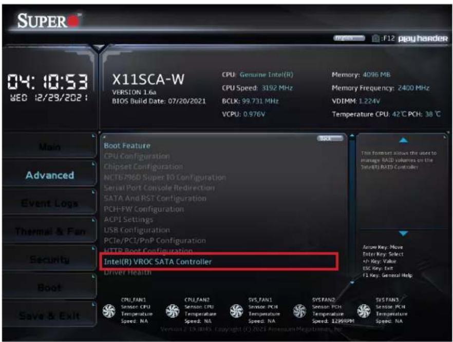
text_image
SUPER 04: 10:53 YEO 12/29/2021 X11SCA-W VERSION 1.6a BIOS Build Date: 07/20/2021 CPU: Genuine Intel(R) CPU Speed: 3192 MHz BCLK: 99.731 MHz VCPU: 0.976V Memory: 4096 MB Memory Frequency: 2400 MHz VDIMM: 1.224V Temperature CPU: 42°C PCH: 38°C Boot Feature CPU Configuration Chipset Configuration NC16796D Super TO Configuration Serial Port Console Redirection SATA And RST Configuration PCH-FW Configuration ACPI Settings USB Configuration PCIe/PCI/PnP Configuration HTTP Boot Configuration Intel(R) VROC SATA Controller Driver Health CPU, FAN1 Sensor, CPU Temperature Speed, NA CPU,FAN2 Sensor, CPU Temperature Speed, NA SYS, FAN1 Sensor, PCH Temperature Speed, NA SYS,FAN2 Sensor, PCH Temperature Speed, 1299RPM SYS, FAN3 Sensor, PCH Temperature Speed, NA Main Advanced Event Logs Thermal & Fan Security Boot Save & Exit Twin Fortset allows the user to manage RAID volumes on the Intel(R) BACH Controller Arrow Key: Move Enter Key: Select +/- Key: Value: ESC Key: Exit F1 Key: General Help▶Create RAID Volume
After selecting Advanced > Intel(R) VROC SATA Controller, the Non-RAID Physical Disks section will show the detected disks for creating RAID volumes. To create a RAID volume, select Create RAID Volume and configure the settings below.
Name
Enter a unique name for the RAID volume. The name must not contain space at the beginning or backslash and must be under 16 characters. The default is Volume0.
RAID Level
Select the desired RAID level for the RAID volume. The options are RAID0(Stripe), RAID1(Mirror), RAID5(Parity), and RAID10(RAID0+1). The RAID level(s) displayed is (are) based on the number of disks connected to the system.
Select Disks
To select a desired RAID disk, select X from the drop-down list. Repeat this step to select all the desired disks for the RAID volume.

Note: For RAID0/RAID1/RAID5/RAID10, the minimum number of disks required is two/two/three/four respectively.
| RAID Setting Minimum Number of Disks Required | |
| RAID 0 Two | |
| RAID 1 Two | |
| RAID 5 Three | |
| RAID 10 Four | |
Strip Size (Available for RAID0/RAID5/RAID10 Only)
Select the desired RAID strip size for your RAID volume. The options vary according to the RAID level you select.
Capacity (GB)
Enter the capacity in gigabytes (GB) of the RAID volume to be created.
RWH Policy (Available for RAID5 Only)
Select a desired RAID Write Hole (RWH) policy when RWH occurs. If no disk has been set as a journaling drive, the options are Distributed PPL and Disable. If any disk has been set as a journaling drive, the options are Distributed PPL, Journaling Drive, and Disable. For details on creating a journaling drive, refer to the Non-RAID Physical Disks section.

Note 1: A RWH occurs when a drive failure and power failure happen simultaneously or close to each other during the write. The events of a drive failure and power failure are
connected and can lead to irrecoverable data or silent data corruption. This is caused by the lack of atomicity of write operations across the disks in the RAID.
Note 2: Partial parity logging (PPL) can be defined as the result of XOR calculation of old data and old parity. PPL is a feature available only for RAID5 volumes. While a power/drive-failure/crash occurring, PPL information helps rebuild the RAID volume and reduce the potential data loss.
Select RWH Journaling Drive (Available for RAID5 Only)
If a journaling drive has been created and RWH Policy is set to Journaling Drive, select a desired journaling drive.
After finishing the configuration, select Create Volume and you will return to the previous screen displaying the information about the created RAID volume. You can click the created RAID volume to view more information.
Delete (a RAID Volume)
To delete a RAID volume you have created, take the steps below:
- Select Advanced > Intel(R) VROC SATA Controller.
- Select the RAID volume to be deleted and then select Delete.
- When asked to confirm deletion of the RAID volume, select Yes to delete the RAID volume.

Note: When deleting a RAID volume, all data on the disks will be deleted as well.
Rebuild (a RAID Volume)
To rebuild a degraded RAID volume, take the steps below after replacing a failed hard drive:
- Select Advanced > Intel(R) VROC SATA Controller.
- Select the RAID volume to be rebuilt and then select Rebuild.
- Select a disk from the list. Then you will return to the previous screen displaying the volume in rebuilding mode.
▶Non-RAID Physical Disks
After selecting Advanced > Intel(R) VROC SATA Controller, the Non-RAID Physical Disks section lists the disks which have not been added to a RAID volume. Select a non-RAID physical disk and you can take the following actions.
Mark as Spare
A spare disk is used for automatic RAID volume rebuilds when the status of "failed", "missing", or "at risk" is detected on the array disk. For a RAID0 volume, only the status of "at risk" will trigger automatic RAID volume rebuilds. Marking a disk as a spare one will remove all data on the disk.
Mark as Journaling Drive
A journaling drive is used as an error event log to record an event when an error occurs to a RAID5 volume. Marking a disk as a journaling drive will remove all data on the disk.
Turn Locate LED On
The feature is not applicable to this motherboard. Please ignore this feature.
Reset to Non-RAID
For a spare or journaling disk or a disk which has been added to a RAID array, you can reset it to a non-RAID disk by taking the steps below:
- Select Advanced > Intel(R) VROC SATA Controller.
- To reset a spare or journaling drive, select the desired drive from the disk list. To reset a RAID member disk, select the RAID volume which contains the disk to be reset and then select the desired member disk.
- Select Reset. When asked to remove the RAID structure on the disk, select Yes to reset the disk.

Note: When resetting a disk, all data on the disk will be deleted as well.
4.4 Event Logs

text_image
SUPER 15:32:41 THU 08/23/20 18 X11SCA-F VERSION 1.0a BIOS Build Date: 08/10/2018 CPU: Intel(R) Xeon(R) E-2146G CPU Speed: 3484 MHz Memory: 8192 MB Memory Frequency: 2133 MHz Change SMBIOS Event Log Settings View SMBIOS Event Log Press » Listen » to change the SMBIO Event Log configuration. Arrow Key: Move Enter Key: Select +/- Key: Value ESC Key: Exit F1 Key: General Help▶Change Smbios Event Log Settings
Enabling/Disabling Options
SMBIOS Event Log
Use this feature to enable all features of the SMBIOS Event Logging during system boot. The options are Disabled and Enabled.
Erasing Settings
Erase Event Log
If No is selected, data stored in the event log will not be erased. Select Yes, Next Reset, data in the event log will be erased upon next system reboot. Select Yes, Every Reset, data in the event log will be erased upon every system reboot. The options are No, "Yes, Next reset", and "Yes, Every reset".
When Log is Full
Select Erase Immediately for all messages to be automatically erased from the event log when the event log memory is full. The options are Do Nothing and Erase Immediately.
SMBIOS Event Log Standard Settings
Log System Boot Event
This feature toggles the System Boot Event logging to enabled or disabled. The options are Disabled and Enabled.
MECI
The Multiple Event Count Increment (MECI) counter counts the number of occurrences that a duplicate event must happen before the MECI counter is incremented. This is a numeric value. The default value is 1.
METW
The Multiple Event Time Window (METW) defines the number of minutes that must pass between duplicate log events before MECI is incremented. This is in minutes, from 0 to 99. The default value is 60.

Note: After making changes on a setting, reboot the system for the changes to take effect.
▶View Smbios Event Log
This feature displays a list of logged Smbios events.
4.5 Thermal & Fan (Available on X11SCA-W)
The Thermal and Fan menu and the features within it are available on the X11SCA-W. This menu displays the system temperature and system health information.

text_image
SUPER 15:58: 14 TKU 09/27/20 18 X11SCA-W VERSION 1.0a BIOS Build Date: 09/27/2018 CPU: Intel(R) Xeon(R) E-2136 CPU Speed: 3292 MHz BCLK: 99.805 MHz VCPU: 1.000V Memory: 8192 MB Memory Frequency: 2133 MHz VDIMM: 1.216V Temperature CPU: 37 C PCH: 34 C Main Advanced Event Logs Thermal & Fan Security Boot Save & Exit System Temperature CPU Temperature : +37 C System Temperature : +28 C Peripheral Temperature : +28 C PCH Temperature : +34 C M.2-P1 : +28 C M.2-P2 : +28 C System Health VCPU : +1.000 V I.2V : +11.916 V SVCC : +5.120 V VDIMM : +1.216 V 3.3V_DL : +3.302 V VCC1_8_DL_PCH : +1.824 V CPU_FAN1 CPU_FAN2 SYS_FAN1 SYS_FAN2 Sensor: CPU Sensor: CPU Sensor: PCN Sensor: PCN Temperature Speed: NA Speed: NA Speed: NA Speed: 1546RPM Speed: NA Arrow Key: Move Inter Key: Select +/- Key: Value ESC Key: Exit F1 Key: General Help SYS_FAN3 Sensor: PCN Temperature Speed: NA Version 2.13.2025 Copyright © 2018 American Pargathemar, Inc.System Temperature
- CPU Temperature
- System Temperature
• Peripheral Temperature - PCH Temperature
M.2-P1
M.2-P2
System Health
• VPU
• 12V
- 5VCC
- VDIMM
- 3.3V_DL
- VCC1_8_DL_PCH
3.3VCC
• VSB - VBAT
▶Fan Control
Fan Control Setting
Fan Speed Control Mode
Use this feature to set the fan speed control mode. The options are Quiet, Stable, Full Speed, and Customize.
4.6 IPMI (Available on X11SCA-F)
IPMI is available on the X11SCA-F. Use this feature to configure Intelligent Platform Management Interface (IPMI) settings.
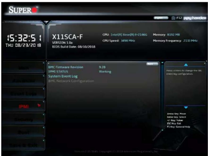
text_image
SUPER 15:32:5 TXU 08/23/20 18 X11SCA-F VERSION 1.0a BIOS Build Date: 08/10/2018 CPU: Intel(R) Xeon(R) E-2146G CPU Speed: 3498 MHz Memory: 8192 MB Memory Frequency: 2133 MHz BMC Firmware Revision 9.28 IPMI STATUS Working System Event Log BMC Network Configuration Press »Enter to change the UI! event log configuration. Amow Key: Move Enter Key: Select +/- Key: Value ESC Key: Exit F1 Key: General Help Version 2 19 3045. Copyright (C) 2018 American MegaStarts, Inc.BMC Firmware Revision
This feature indicates the IPMI firmware revision used in your system.
IPMI Status (Baseboard Management Controller)
This feature indicates the status of the IPMI firmware installed in your system.
▶System Event Log
SEL Components
Select Enabled for all system event logging at bootup. The options are Disabled and Enabled.
Erase SEL
Select Yes, On next reset to erase all system event logs upon next system reboot. Select Yes, On every reset to erase all system event logs upon each system reboot. Select No to keep all system event logs after each system reboot. The options are No, "Yes, On next reset", and "Yes, On every reset".
When SEL is Full
This feature allows the user to decide what the BIOS should do when the system event log is full. Select Erase Immediately to erase all events in the log when the system event log is full. The options are Do Nothing and Erase Immediately.

Note: After making changes on a setting, be sure to reboot the system for the changes to take effect.
▶BMC Network Configuration
IPMI LAN Selection
IPMI Network Link Status
Update IPMI LAN Configuration
Select Yes for the BIOS to implement all IP/MAC address changes at the next system boot. The options are Yes and No.
*If the feature above is set to Yes, the following feature will become available for configuration:
Configuration Address Source
This feature allows the user to select the source of the IP address for this computer. If Static is selected, you will need to know the IP address of this computer and enter it to the system manually in the field. If DHCP is selected, the BIOS will search for a DHCP (Dynamic Host Configuration Protocol) server in the network that is attached to and request the next available IP address for this computer. The options are Static and DHCP.
Station IP Address
This feature displays the Station IP address for this computer. This should be in decimal and in dotted quad form (i.e., 192.168.10.253).
Subnet Mask
This feature displays the sub-network that this computer belongs to. The value of each three-digit number separated by dots should not exceed 255.
Station MAC Address
This feature displays the Station MAC address for this computer. MAC addresses are six two-digit hexadecimal numbers.
Gateway IP Address
This feature displays the Gateway IP address for this computer. This should be in decimal and in dotted quad form (i.e., 172.31.0.1).
VLAN
This feature enables the IPMI VLAN function. The options are Disabled and Enabled.
*If the feature above is set to Enable, the following feature will become available for configuration:
VLAN ID
Use this feature to enter the VLAN ID. The default setting is 0.
IPV6 Support
This feature enables LAN1 IPv6 Support. The options are Disabled or Enabled.
Configuration Address source
This feature configures the LAN channel parameters, either statically or dynamically. The options are Static and DHCP.
4.7 Security
Use this submenu to create Administrator and User passwords. Using ONLY an Administrator password limits access to BIOS setup. Using ONLY a User password will lock unauthorized users from booting the system and/or entering the BIOS setup.

text_image
SUPER 15:33:0 THU 08/23/20 18 X11SCA-F VERSION 1.0a BIOS Build Date: 08/10/2018 CPU: Intel(R) Xeon(R) E-2146G CPU Speed: 3491 MHz Memory: 8192 MB Memory Frequency: 2133 MHz Administrator Password Not Installed User Password Not Installed Password Description If the Administrator / User password is set, then this only limits access to Setup and is asked for when entering Setup. Please set Administrator password first in order for setting User password, if clear Administrator password, User password will be cleared as well. The password length must be in the following range: Minimum length 3 Maximum length 20 Set Administrator Password Arrow Key: Move Enter Key: Select +/- Key: Value ESC Key: Exit F1 Key: General HelpAdministrator Password
Press
*If the password has been created, the feature of User Password below will become available for configuration.
User Password
Press
Password Check
Select Setup for the system to check for a password at Setup. Select Always for the system to check for a password at bootup or upon entering the BIOS Setup utility. The options are
Setup and Always.
Hard Drive Security Frozen
Use this feature to disable or enable the BIOS security frozen command to SATA and NVMe devices. The options are Enabled and Disabled.
HDD Security Configuration
Press
Secure Boot
This section displays the contents of the following secure boot features:
- System Mode
- Secure Boot
Attempt Secure Boot
Use this feature to enable secure boot. The options are Disabled and Enabled.

Note: After making changes on a setting, be sure to reboot the system for the changes to take effect.
Secure Boot Mode
Use this feature to configure Secure Boot variables without authentication. The options are
Customized and Standard.
*If the feature of Secure Boot Mode is set to Customized, the following features will become available for configuration:
CSM Support
This feature is for manufacturing debugging purposes.
Enter Audit Mode
This submenu can only be used if current System Mode is set to User. The PK variable will be erased on transition to Audit Mode.
Enter Deployed Mode
Press
Exit Deployed Mode
Press
Key Management
Vendor Keys
Provision Factory Defaults
Select Enabled to install the default Secure-Boot keys set by the manufacturer. The options are Disabled and Enabled.
Press
Reset to Setup Mode
This feature resets the system to Setup Mode. The options are Yes and No.
Save All Secure Boot variables
This feature allows the user to decide if all secure boot variables should be saved.
Enroll EFi Image
This feature allows the image to run in Secure Boot Mode. Enroll SHA256 Hash Certificate of the image into the Authorized Signature Database.
Device Guard Ready
Remove 'UEFI CA' from DB
Use this feature to remove the Microsoft UEFI CA certificate from the database.
Restore DB Defaults
Select Yes to restore the DB defaults or select No to cancel.
Secure Boot Variable / Size / Keys / Key Source
Platform Key (PK)
This feature allows the user to configure the settings of the platform keys.
Details
Review details on current settings of the platform keys.
Export
This feature allows the user to export Platform Keys to an available file system.
Update
Select Yes to load the new Platform Keys (PK) from the manufacturer's defaults. Select No to load the Platform Keys from a file.
Delete
Select OK to confirm deletion of the Platform Key from NVRAM.
Key Exchange Keys
Details
Review details on current settings of the Key Exchange Keys.
Export
This feature allows the user to export Key Exchange Keys to an available file system.
Update
Select Yes to load the KEK from the manufacturer's defaults. Select No to load the KEK from a file.
Append
Select Yes to add the KEK from the manufacturer's defaults list to the existing KEK. Select No to load the KEK from a file.
Delete
Select Yes to delete the Key Exchange Keys. Select No to delete only a certificate from the key database.
Authorized Signatures
Details
Review details on current settings of Authorized Signatures.
Export
This feature allows the user to export Authorized Signatures to an available file system.
Update
Select Yes to load the factory default DB. Select No to load the DB from an external file.
Append
Select Yes to add the database from the manufacturer's defaults to the existing DB. Select No to load the DB from a file.
Delete
Select Yes to delete the Authorized Signatures key database. Select No to delete only a certificate from the key database.
Forbidden Signatures
Details
Review details on current settings of the Forbidden Signatures.
Export
This feature allows the user to export Forbidden Signatures to an available file system.
Update
Select Yes to load the DBX factory default 'dbx.' Select No to load it from an external file.
Append
Select Yes to add the DBX from the manufacturer's defaults to the existing DBX. Select No to load the DBX from a file.
Delete
Select Yes to delete the Forbidden Signatures key database. Select No to delete only a certificate from the key database.
Authorized TimeStamps
Details
Review details on current settings of the Authorized TimeStamps.
Export
This feature allows the user to export Authorized TimeStamps to an available file system.
Update
Select Yes to load the DBT from the manufacturer's defaults. Select No to load the DBT from a file.
Append
Select Yes to add the DBT from the manufacturer's defaults list to the existing DBT. Select No to load the DBT from a file.
Delete
Select Yes to delete the Authorized TimeStamps key database. Select No to delete only a certificate from the key database.
OsRecovery Signatures
Details
Review details on current settings of the Authorized TimeStamps.
Export
This feature allows the user to export Authorized TimeStamps to an available file system.
Update
Select Yes to load the DBT from the manufacturer's defaults. Select No to load the DBT from a file.
Append
Select Yes to add the DBT from the manufacturer's defaults list to the existing DBT. Select No to load the DBT from a file.
Delete
Select Yes to delete the Authorized TimeStamps key database. Select No to delete only a certificate from the key database.
4.8 Boot
Use this menu to configure boot settings.
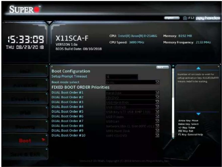
text_image
SUPER 15:33:09 THU 08/23/20 18 X11SCA-F VERSION 1.0a BIOS Build Date: 08/10/2018 CPU: Intel(R) Xeon(R) E-2146G CPU Speed: 3490 MHz Memory: 8192 MB Memory Frequency: 2133 MHz Boot Configuration Setup Prompt Timeout Boot mode select DUAL FIXED BOOT ORDER Priorities DUAL Boot Order #1 DUAL Boot Order #2 DUAL Boot Order #3 DUAL Boot Order #4 DUAL Boot Order #5 DUAL Boot Order #6 DUAL Boot Order #7 DUAL Boot Order #8 DUAL Boot Order #9 DUAL Boot Order #10 Hard Disk CD/DVD USB Hard Disk USB CD/DVD USB Key-TTI USB RMP 110V USB Flouys USB Lan Network IDA CL Slot 00FF v01.1 UEFI Hard Disk UEFI CD/DVD Number of seconds to wait for setup activation key: 65535/0aFHH means moefinite waiting. Arrow Key: Move Enter Key: Select +/- Key: Value ESC Key: Exit F1 Key: General HelpSetup Prompt Timeout
This feature controls how long (in seconds) the boot process will wait for the Setup Activation key (normally
Boot mode select
Use this feature to select the boot mode. The options are LEGACY, UEFI, and DUAL.
FIXED BOOT ORDER Priorities
Use this feature to set the boot order priority. The number of boot options shown is dependent on the boot mode selected (above).
Add Boot Option (Available on X11SCA-F)
Use this feature to add a new EFI boot option to the boot order.
Delete Boot Option
This feature removes an EFI boot option from the boot order.
Add New Driver Option (Available on X11SCA-F)
Use this feature to add a new EFI driver option to the driver order.
Delete Driver Option
Use this feature to remove an EFI driver option from the driver order.
UEFI Application Boot Priorities
Use this feature to specify the boot device priority sequence from an available UEFI Application.
UEFI USB Key Drive BBS Priorities (Available on X11SCA-F)
Use this feature to specify the boot device priority sequence from available UEFI USB Key drives.
USB Key Drive BBS Priorities (Available on X11SCA-F)
Use this feature to specify the boot device priority sequence from available USB Key drives.
Network Drive BBS Priorities
Use this feature to specify the boot device priority sequence from available network drives.
4.9 Save & Exit
Use this menu to save settings and exit.
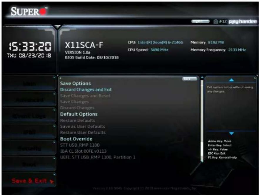
text_image
SUPER 15:33:20 TXU 08/23/20 18 X11SCA-F VERSION 1.0a BIOS Build Date: 08/10/2018 CPU: Intel(R) Xeon(R) E-2146G CPU Speed: 3490 MHz Memory: 8192 MB Memory Frequency: 2133 MHz Main Advanced Event Logs IPMI Security Boot Save & Exit > Save Options Discard Changes and Exit Save Changes and Reset Save Changes Discard Changes Default Options Restore Defaults Save as User Defaults Restore User Defaults Boot Override STT USB_RMP 1100 IBA CL Slot 00FE v0113 UEFI: STT USB_RMP 1100, Partition 1 Exit system setup without saving any changes. Amse Key: Move Enter Key: Select +/- Key: Value ESC Key: Exit F1 Key: General Help Version 2.19.004's Copyright © 2018 American Key stories, Pp.Save Options
Discard Changes and Reset
This option will save the changes that have been made and will reboot the system.
Save Changes and Reset
This option will save the changes that have been made and will reboot the system.
Save Changes
This option will save the changes but will remain in setup mode.
Discard Changes
This option will discard the changes but will remain in setup mode.
Default Options
Restore Defaults
This option will load the factory-stored optimized defaults and remain in setup mode.
Save as User Defaults
This option will save the changes as user-specified defaults and remain in setup mode.
This option will load previously saved user-specified defaults and remain in setup mode.
Boot Override
STT USB_RMP 1100
This feature force boots STT USB_RMP 1100. This will restart the system.
IBA CL Slot 00FE v0113
This feature force boots IBA CL Slot 00FE v0113. This will restart the system.
UEFI: STT USB_RMP 1100, Partition 1
This feature force boots the Built-in EFI Shell.
Appendix A
BIOS Codes
BIOS Error POST (Beep) Codes
During the POST (Power-On Self-Test) routines, which are performed upon each system boot, errors may occur.
Non-fatal errors are those which, in most cases, allow the system to continue to boot. These error messages normally appear on the screen.
Fatal errors will not allow the system to continue with bootup. If a fatal error occurs, you should consult with your system manufacturer for possible repairs.
These fatal errors are usually communicated through a series of audible beeps. The numbers on the fatal error list correspond to the number of beeps for the corresponding error.
| BIOS Beep (POST) Codes | ||
| Beep Code Error | Message Description | |
| 1 beep Refresh Ready to boot | ||
| 5 short, 1 long Memory error No memory detected in system | ||
| 5 beeps No con-in or con-out devices | Con-in includes USB or PS/2 keyboard, PCI or serial console redirection, and IPMI KVM or SOL.Con-out includes the video controller, PCI or serial console redirection, and IPMI SOL | |
| 1 beep per device R | Refresh 1 beep for each USB device detected | |
| IPMI Error Codes | ||
| Beep Code Error | Message Description | |
| 1 long continuous System OH System overheat condition | ||
Appendix B
Software
After the hardware has been installed, you can install the Operating System (OS), configure RAID settings and install the drivers.
B.1 Microsoft Windows OS Installation
If you will be using RAID, you must configure RAID settings before installing the Windows OS and the RAID driver. Refer to the RAID Configuration User Guides posted on our website at www.supermicro.com/support/manuals.
Installing the OS
- Create a method to access the MS Windows installation ISO file. That might be a DVD, perhaps using an external USB/SATA DVD drive, or a USB flash drive, or the IPMI KVM console.
- Retrieve the proper RST/RSTe driver. Go to the Supermicro web page for your motherboard and click on "Download the Latest Drivers and Utilities", select the proper driver, and copy it to a USB flash drive.
- Boot from a bootable device with Windows OS installation. You can see a bootable device list by pressing F11 during the system startup.
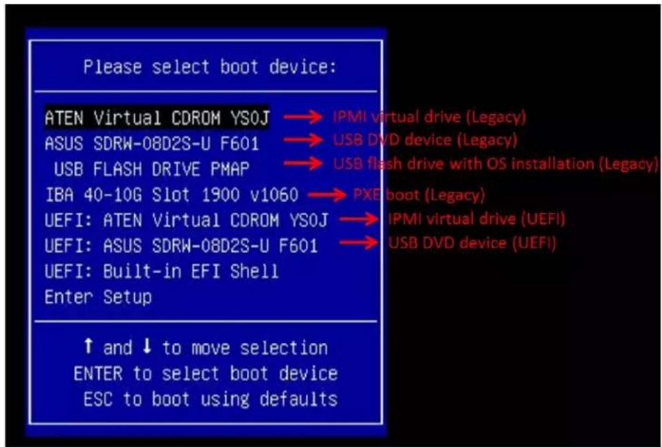
text_image
Please select boot device: ATEN Virtual CDROM YSOJ → IPMI virtual drive (Legacy) ASUS SDRW-08D2S-U F601 → USB DVD device (Legacy) USB FLASH DRIVE PMAP → USB flash drive with OS installation (Legacy) IBA 40-10G Slot 1900 v1060 → PXE boot (Legacy) UEFI: ATEN Virtual CDROM YSOJ → IPMI virtual drive (UEFI) UEFI: ASUS SDRW-08D2S-U F601 → USB DVD device (UEFI) UEFI: Built-in EFI Shell Enter Setup ↑ and ↓ to move selection ENTER to select boot device ESC to boot using defaults- During Windows Setup, continue to the dialog where you select the drives on which to install Windows. If the disk you want to use is not listed, click on "Load driver" link at the bottom left corner.
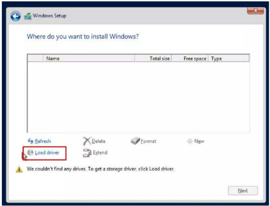
text_image
Where do you want to install Windows? Name Total size Free space Type Refresh Delete Format New Load driver Extend We couldn't find any drives. To get a storage driver, click Load driver. NextTo load the driver, browse the USB flash drive for the proper driver files.
- For RAID, choose the SATA/sSATA RAID driver indicated then choose the storage drive on which you want to install it.
-
For non-RAID, choose the SATA/sSATA AHCI driver indicated then choose the storage drive on which you want to install it.
-
Once all devices are specified, continue with the installation.
- After the Windows OS installation has completed, the system will automatically reboot multiple times.
B.2 Driver Installation
The Supermicro website that contains drivers and utilities for your system is at https://www.supermicro.com/wftp/driver. Some of these must be installed, such as the chipset driver.
After accessing the website, go into the CDR_Images (in the parent directory of the above link) and locate the ISO file for your motherboard. Download this file to a USB flash drive or a DVD. (You may also use a utility to extract the ISO file if preferred.)
Another option is to go to the Supermicro website at http://www.supermicro.com/products/. Find the product page for your motherboard, and "Download the Latest Drivers and Utilities".
Insert the flash drive or disk and the screenshot shown below should appear.
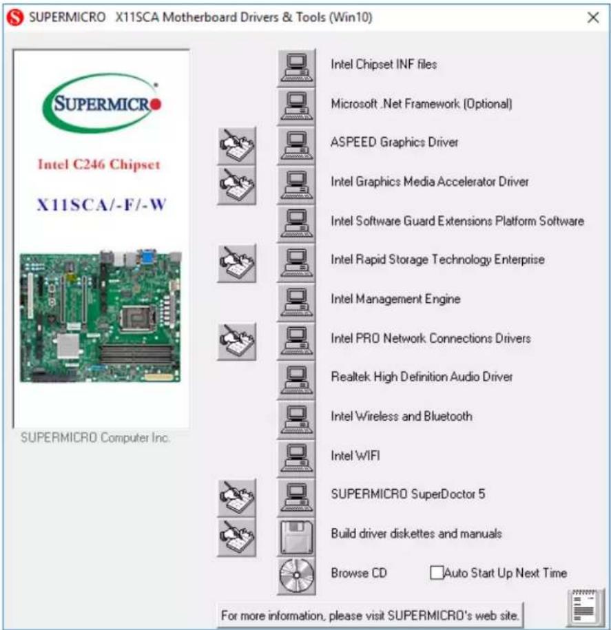
text_image
SUPERMICRO X11SCA Motherboard Drivers & Tools (Win10) Intel C246 Chipset X11SCA/-F/-W SUPERMICRO Computer Inc. Intel Chipset INF files Microsoft .Net Framework (Optional) ASPEED Graphics Driver Intel Graphics Media Accelerator Driver Intel Software Guard Extensions Platform Software Intel Rapid Storage Technology Enterprise Intel Management Engine Intel PRO Network Connections Drivers Realtek High Definition Audio Driver Intel Wireless and Bluetooth Intel WIFI SUPERMICRO SuperDoctor 5 Build driver diskettes and manuals Browse CD Auto Start Up Next Time For more information, please visit SUPERMICRO's web site.Note: Click the icons showing a hand writing on paper to view the readme files for each item. Click the computer icons to the right of these items to install each item (from top to bottom) one at a time. After installing each item, you must reboot the system before moving on to the next item on the list. The bottom icon with a CD on it allows you to view the entire contents.
B.3 SuperDoctor® 5
The Supermicro SuperDoctor 5 is a program that functions in a command-line or web-based interface for Windows and Linux operating systems. The program monitors such system health information as CPU temperature, system voltages, system power consumption, fan speed, and provides alerts via email or Simple Network Management Protocol (SNMP).
SuperDoctor 5 comes in local and remote management versions and can be used with Nagios to maximize your system monitoring needs. With SuperDoctor 5 Management Server (SSM Server), you can remotely control power on/off and reset chassis intrusion for multiple systems with SuperDoctor 5 or IPMI. SuperDoctor 5 Management Server monitors HTTP and SMTP services to optimize the efficiency of your operation.

Note: The default User Name and Password for SuperDoctor 5 is ADMIN / ADMIN.
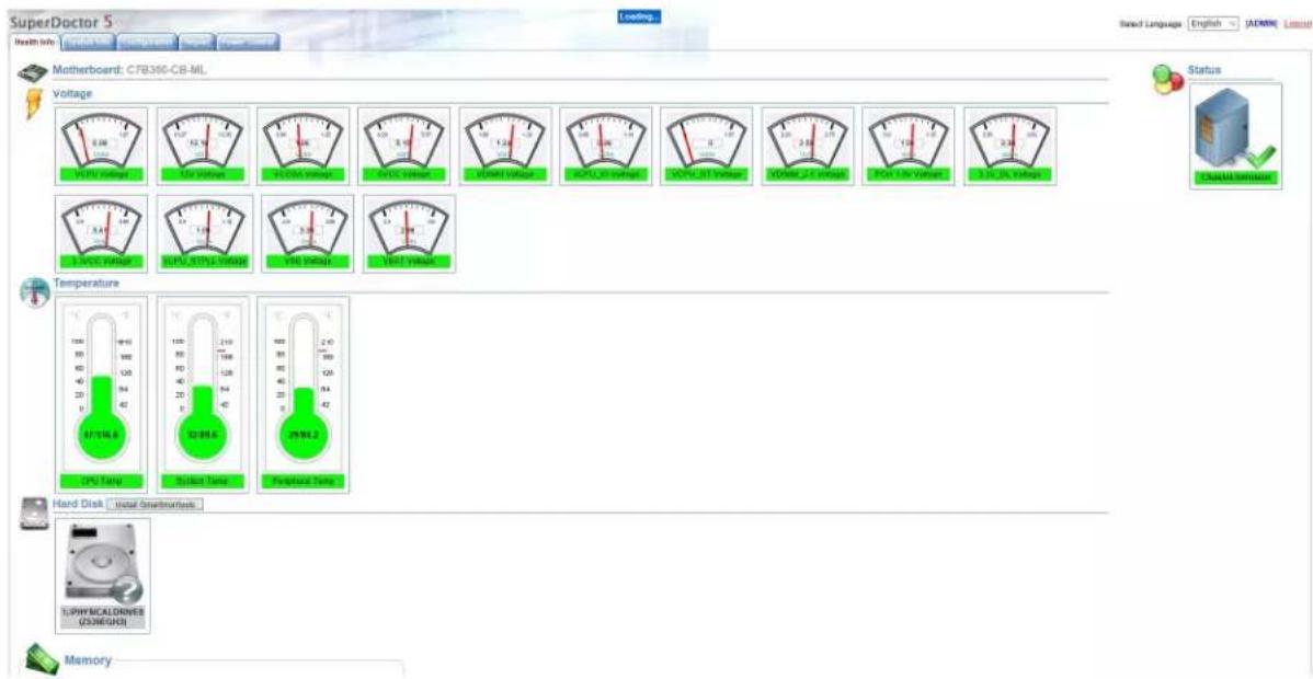
text_image
SuperDoctor 5 Health info Matherboard: C7B386-CB-ML Voltage Voltage Range 100 MHz 2.0 V 3.0 V 4.0 V 5.0 V 6.0 V 7.0 V 8.0 V 9.0 V 10.0 V 11.0 V 12.0 V 13.0 V 14.0 V 15.0 V 16.0 V 17.0 V 18.0 V 19.0 V 20.0 V 21.0 V 22.0 V 23.0 V 24.0 V 25.0 V 26.0 V 27.0 V 28.0 V 29.0 V 30.0 V 31.0 V 32.0 V 33.0 V 34.0 V 35.0 V 36.0 V 37.0 V 38.0 V 39.0 V 40.0 V 41.0 V 42.0 V Temperature 100 MHz 80 MHz 60 MHz 40 MHz 20 MHz 0 MHz DPU Famp 100 MHz 80 MHz 60 MHz 40 MHz 20 MHz 0 MHz Standard Famp 240 MHz 168 MHz 128 MHz 94 MHz 40 MHz 20 MHz 42 MHz Physical Time 168 MHz 80 MHz 60 MHz 40 MHz 20 MHz 0 MHz Physical Time (23/8GHz) Physical Time (23/8GHz) Physical Time (23/8GHz) Physical Time (23/8GHz) Physical Time (23/8GHz) Physical Time (23/8GHz) Physical Time (23/8GHz) Physical Time (23/8GHz) Physical Time (23/8GHz) Physical Time (23/8GHz) Physical Time (23/8GHz) Physical Time (23/8GHz) Functional Time (23/8GHz) Functional Time (23/8GHz) Functional Time (23/8GHz) Functional Time (23/8GHz) Functional Time (23/8GHz) Functional Time (23/8GHz) Functional Time (23/8GHz) Functional Time (23/8GHz) Functional Time (23/8GHz) Functional Time (23/8GHz) Functional Time (23/8GHz) FunctionalTime (23/8GHz) Functional Time (23/8GHz) Functional Time (23/8GHz) Functional Time (23/8GHz) Functional Time (23/8GHz) Functional Time (23/8GHz) Functional Time (23/8GHz) Functional Time (23/8GHz) Functional Time (23/8GHz) Functional Time (23/8GHz) Functional Time (23/8GHz) Functional Time(23/8GHz) Functional Time(23/8GHz) Functional Time(23/8GHz) Functional Time(23/8GHz) Functional Time(23/8GHz) Functional Time(23/8GHz) Functional Time(23/8GHz) Functional Time(23/8GHz) Functional Time(23/8GHz) Functional Time(23/8GHz) Functional Time(23/8GHz) Functional Time( 23/8GHz ) Functional Time( 23/8GHz ) Functional Time( 23/8GHz ) Functional Time( 23/8GHz ) Functional Time( 23/8GHz ) Functional Time( 23/8GHz ) Functional Time( 23/8GHz ) Functional Time( 23/8GHz ) Functional Time( 23/8GHz ) Functional Time( 23/8GHz ) Functional Time( 23/8GHz )B.4 IPMI (X11SCA-F only)
The motherboard supports the Intelligent Platform Management Interface (IPMI). IPMI is used to provide remote access, monitoring and management. There are several BIOS settings that are related to IPMI.
For general documentation and information on IPMI, please visit our website at: http://www.supermicro.com/products/nfo/IPMI.cfm.
B.5 Logging into the BMC (Baseboard Management Controller) (X11SCA-F only)
Supermicro ships standard products with a unique password for the BMC user. This password can be found on a label on the motherboard.
When logging in to the BMC for the first time, please use the unique password provided by Supermicro to log in. You can change the unique password to a user name and password of your choice for subsequent logins.
For more information regarding BMC passwords, please visit our website at http://www.supermicro.com/bmcpassword.
Appendix C
Standardized Warning Statements
The following statements are industry standard warnings, provided to warn the user of situations that might potentially cause bodily injury. Should you have questions or experience difficulty, contact Supermicro's Technical Support department for assistance. Only certified technicians should attempt to install or configure components.
Read this section in its entirety before installing or configuring components.
These warnings may also be found on our website at http://www.supermicro.com/about/policies/safety_information.cfm.
Battery Handling

Warning! There is the danger of explosion if the battery is replaced incorrectly. Replace the battery only with the same or equivalent type recommended by the manufacturer. Dispose of used batteries according to the manufacturer's instructions
電池の取り扱い
Warning! Ultimate disposal of this product should be handled according to all national laws and regulations.
製品の廃棄
Warning: Do not upgrade the BIOS unless your system has a BIOS-related issue. Flashing the wrong BIOS can cause irreparable damage to the system. In no event shall Supermicro be liable for direct, indirect, special, incidental, or consequential damages arising from a BIOS update. If you need to update the BIOS, do not shut down or reset the system while the BIOS is updating to avoid possible boot failure.
D.1 Overview
The Unified Extensible Firmware Interface (UEFI) provides a software-based interface between the operating system and the platform firmware in the pre-boot environment. The UEFI specification supports an architecture-independent mechanism that will allow the UEFI OS loader stored in an external storage device to boot the system. The UEFI offers a clean, hands-off control to a computer system at bootup.
D.2 Recovering the UEFI BIOS Image
A UEFI BIOS flash chip consists of a recovery BIOS block and a main BIOS block (a main BIOS image). The boot block contains critical BIOS codes, including memory detection and recovery codes for the user to flash a new BIOS image if the original main BIOS image is corrupted. When the system power is on, the boot block codes execute first. Once it is completed, the main BIOS code will continue with system initialization and bootup.

Note 1: Follow the BIOS recovery instructions below for BIOS recovery when the main BIOS boot crashes.
Note 2: When the BIOS boot block crashes, you will need to follow the procedures to make a Returned Merchandise Authorization (RMA) request (see Section 3.5 for more information). Also, you may use the Supermicro Update Manager (SUM) Out-of-Band (OOB) (https://www.supermicro.com.tw/products/nfo/SMS_SUM.cfm) to reflash the BIOS.
D.3 Recovering the BIOS Block with a USB Device
This feature allows the user to recover a BIOS image using a USB-attached device without additional utilities used. A USB flash device such as a USB Flash Drive, or a USB CD/DVD
ROM/RW device can be used for this purpose. However, a USB Hard Disk drive cannot be used for BIOS recovery at this time.
The file system supported by UEFI is FAT (including FAT12, FAT16, and FAT32) installed on a bootable or non-bootable USB-attached device. However, the BIOS might need several minutes to locate the SUPER.ROM file if the media size becomes too large because it contains too many folders and files.
To perform UEFI BIOS recovery using a USB-attached device, follow the instructions below.
- Using a different machine, copy the "SUPER.ROM" binary image file into the disc Root "\" Directory of a USB device or a writeable CD/DVD.

Note: If you cannot locate the "SUPER.ROM" file in your driver disk, visit our website at www.supermicro.com to download the BIOS image into a USB flash device and rename it to "SUPER.ROM" for BIOS recovery use.
- Insert the USB device that contains the new BIOS image ("SUPER.ROM") into your USB drive and power on the system
- After locating the new BIOS binary image, the system will enter the BIOS Recovery menu automatically as shown below.

text_image
SUPERMICR®www.supermicro.com
M1-390 Implementation...
BIC 39:18,188,160,475
P()

Note: If the following screen displays, please load the "SUPER.ROM" file to the root folder and connect this folder to the system. You can do so by inserting a USB device that contains the new "SUPER.ROM" image to your machine for BIOS recovery.

text_image
SUPERMICR®www.supermicro.com
FEI—04E Phase Start...
2010.10.16.17
07

Note: At this point, you may decide if you want to start the BIOS recovery. If you decide to proceed with BIOS recovery, follow the procedures below.

text_image
SUPER 03:47:52 ROM 04/23/20 18 X11SCA-F VERSION T201BD42311B22 BIOS Build Date: 04/23/2018 CPU: Reset(R) Read(R) E-2180G CPU Speed: 3795 MHz Memory: 8162 MHz Memory Frequency: 2133 MHz Please select blocks you want to update Reset NVRAM Boot Block Update SMNOS Preservation Forward with Back uppose Arrow Any Move Clearing Select in Key States DC Day, Det F3 Key Connection Help- When the screen as shown above displays, use the arrow keys to select the item "Proceed with flash update" and press the
key. You will see the BIOS recovery progress as shown in the screen below.

Note : Do not interrupt the BIOS flashing process until it has completed.

text_image
SUPER 03:48:11 Roh 04/29/20 8 X11SCA-F VERSION: TC0180423113022 RiOS Main Date: 06/29/2018 CPU: Intel® AdvancedE-2100G CPU Speed: 770 MHz Memory: 835 MHz Memory Frequency: 213 MHz Flash Update Updating main features Progress: 1.6s © Key Value 100% Max © Key Summary- After the BIOS recovery process is completed, press any key to reboot the system.
