VCS-MCU91B0 - Video Conferencing System Dahua Technology - Free user manual and instructions
Find the device manual for free VCS-MCU91B0 Dahua Technology in PDF.

User questions about VCS-MCU91B0 Dahua Technology
0 question about this device. Answer the ones you know or ask your own.
Ask a new question about this device
Download the instructions for your Video Conferencing System in PDF format for free! Find your manual VCS-MCU91B0 - Dahua Technology and take your electronic device back in hand. On this page are published all the documents necessary for the use of your device. VCS-MCU91B0 by Dahua Technology.
USER MANUAL VCS-MCU91B0 Dahua Technology
Video Conferencing System Multi-Point Control Unit DH-VCS-MCU91XX series
User Manual
V1.0.1
Zhejiang Dahua Technology Co., Ltd
Copyright Statement
© Zhejiang Dahua Technology Co., Ltd. 2016. All rights reserved.
Information contained in this document should not be reproduced, spread, distributed or stored by any person in any form without prior written license of Zhejiang Dahua Technology Co., Ltd. (hereinafter referred to as "Dahua").
The products referred to in this document may contain software proprietary to Dahua or, probably, a third party. The above-mentioned software should not be reproduced, distributed, modified, extracted, decompiled, disassembled, decoded, reverse engineered, leased, transferred or sub-licensed or other copyright violations.
Declaration of Trademark
@lhua , , , and @lhua HDCVI 华视微讯
registered trademarks of Zhejiang Dahua Technology Co., Ltd. Other trademarks or company names that may be referred to in this document are properties of their respective owners.
Update and Modification
To enhance the security of this product and provide you better user experience, Dahua may improve this product by automatically updating the software without prior notice and assume no responsibility.
Dahua reserves the right to change any information contained in the document at any time, which will be then included in a new version, without prior notice. Some features of the product allow subtle differences before and after change.
Overview
This document describes in detail the quick configuration of the DH-VCS-MCU91XX series.
Applicable to models: DH-VCS-MCU91B0 and DH-VCS-MCU91F0.

Note
The names of the models will henceforth be shortened as MCU9110 and MCU9150.
Symbol Conventions
For the purpose of this document, the following signs that may exist herein mean as below:
| Symbol | Description | |
 | Danger | Danger indicates an imminently hazardous situation which, if not avoided, will result in death or serious injury. |
 | Warning | Warning indicates a moderately or lowly hazardous situation which, if not avoided, will result in minor or moderate injury. |
 | Caution | Caution alerts you to possible equipment damage, data loss, performance degradation or unpredictable results if you do not follow instructions. |
 | Anti-static | Alert you to static-sensitive equipment. |
 Against Electric Shock Against Electric Shock | Protection | Alert you to high voltage. |
 Laser Radiation Laser Radiation | Alert you to intense laser radiation. | |
| Tip | Help you with solving a problem or saving your time. | |
| Note | Additional information for the main body, which can be known as an emphasis and supplement to the main body. | |
Before using the product, read and abide by the following requirements to prevent damage to the product or your belongings.

Caution
- Transport, use, and store the product only under the appropriate temperatures and humidity.
- Install the product in a well-ventilated place and do not block the device's air vents.
• Install the product in a steady place. - Do not place the product in damp, dusty, or smoky areas.
- Do not place the product in direct sun light or near a heat source.
- Do not let the product come in contact with liquids.
- Do not disassemble the product at will.

Warning
- Turn off all power sources when opening the device cover or when repairing the device to prevent electric shock.
- Use a new battery of the same kind to replace the old one.
- Use the recommended power cord and use it within its rated specifications.
- If a power plug or appliance coupler is used as a disconnecting device, please ensure that the disconnecting device is always easy to operate.
Important Statements
• The physical product shall prevail while this User Manual is for reference only.
- The product will automatically update itself. If there is an upgrade, no notifications will be given.
- For the latest procedure and supplementary documentation, please contact the service center.
- Should there be any doubts or any disputes over the product instructions, the company reserves the rights of final interpretation.
Legal Statement...... I
Preface....I
Safety Precautions.... II
1 Overview.... 1
1.1 Introduction to the Product.... 1
1.2 Port Descriptions.... 2
1.2.1 MCU91B0 2
1.2.2 MCU91F0....4
2 Networking Diagram....1
3 Web Operation 2
3.1 Config Flow 2
3.2 System Login 2
3.3 Quick Guide 3
3.4 Device Management....7
3.4.1 Adding Devices 8
3.4.2 Modifying Device 10
3.4.3 Deleting Devices....11
3.5 Service Management 12
3.5.1 Service Status.... 12
3.5.2 Service Config 12
3.6 Conference Management 13
3.6.1 Creating Meeting 13
3.6.2 Meeting Control 18
3.6.3 Booked Meetings....20
3.6.4 Favorite Meetings 21
3.6.5 Meeting History....22
3.7 System Management 23
3.7.1 User Management 23
3.7.2 System Management.... 25
3.7.3 Maintenance Management 30
3.7.4 Platform Access 33
3.7.5 Config.... 34
3.7.6 TV Wall Config 36
3.8 Gateway Management.... 37
3.8.1 All Gateways 37
3.8.2 Cloud Proxy 38
3.8.3 H323 Gateway 38
1.1 Introduction to the Product
| Model | Product Introduction | Hardware architecture |
| MCU91B0 | The MCU91B0 is a fully adaptable, cost-effective, and high performance MCU product, suitable for small-scale conference system networks. Smart connection with various terminals provides the ultimate conferencing experience for users.Supports 10 meeting places at 1080P 30FPS for fully adaptable conferencing, and 5 simultaneous meetings including management for 32 conference terminals. | 1U rack.4 USB ports at the back and 2 USB2.0 ports at the front for convenient debugging.1 RS232 debugging port.Dual gigabit Ethernet ports. |
| MCU91F0 | MCU91F0 is a new generation high performance, high density, high reliability, and fully adaptable MCU product. It is suitable for mid-sized conference system networks and can be stacked to implement large conference system networks. Smart connection with various terminals provides the ultimate conferencing experience for users.Supports 80 meeting places at 1080P 30FPS for fully adaptable conferencing, and 40 simultaneous meetings including management for 256 conference terminals. | 2U rack.4 hot-swappable nodes.Supports 1 + 1 redundant power supply.4 gigabit Ethernet ports, 2 USB ports, and 1 RS232 debugging port at each node. |
1.2 Port Descriptions
1.2.1 MCU91B0
1.2.1.1 Front Panel
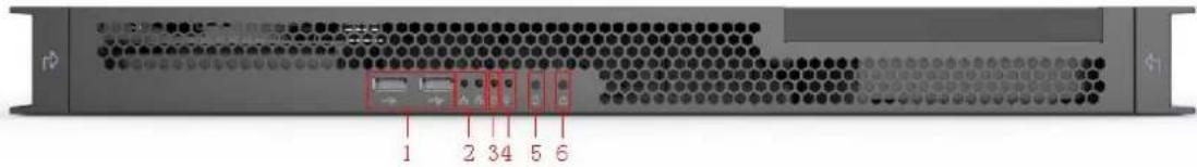
text_image
1 2 3 4 5 6Figure 1-1
| Serial Number | Name | Function Description |
| 1 | USB ports | Connect to mouse/keyboard. |
| 2 | Network indicator | Network indicator lights for network port 1 and 2 on the back panel of MCU91B0.Flashes yellow when the device is successfully connected to the network. |
| 3 | Hard disk indicator | Red light Flashes when hard disk reads and writes. |
| 4 | Power indicator | A blue light will show when power is connected. |
| 5 | Reset button | • Short press for soft reset.• Long press for hard reset.NoteA forced reset may lead to data loss. |
| 6 | Power button | Switches on the device. Short press the power button to turn the device on/off. |
Table 1-1
1.2.1.2 Back Panel
- Master device: When connected using the master device network port, the device will be the master device. It will be set as the core scheduling and media processing server.
- Slave device: When connected using the slave device network port, the device will be a slave device. It will be set as the media processing server.
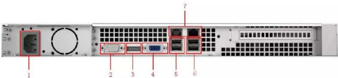
text_image
1 2 3 4 5 6 7Figure 1-2
| Serial Number | Name | Function Description |
| 1 | Power port | Connects to 220V AC power source. |
| 2 | RS232 port | Used for regular serial debugging, IP address configuration, and transparent serial data transmission. |
| 3 | DP port | Use the accompanying DP to VGA cable to connect to the monitor. |
| 4 | VGA port | Not supported currently. |
| 5 | USB 2.0 port | Connect to mouse/keyboard. |
| 6 | USB 3.0 port | |
| 7 | Network port | Used to connect to a network. The left side is the master device network port, and the right side is the slave device network port.Refer to step 5 of “3.3 Quick Guide” for system network parameter setting.NoteLeft port default IP address: 192.168.1.108.Right port default IP address: 192.168.2.108. |
Table 1-2
1.2.2 MCU91F0
1.2.2.1 Front Panel
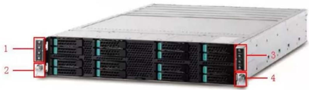
text_image
1 2 3 4Figure 1-3
| Serial Number | Name | Function Description |
| 1 | Indicator light for board 1 | Indicator light for the host board in the MCU91F0 back panel.From top to bottom:Board 1, host 2Board 1, host 1Board 3, host 2Board 3, host 1 |
| 2 | Power switch 1 | Power switch for board 1 and 3. |
| 3 | Indicator light for board 2 | Indicator light for the host board in the MCU91F0 back panel.From top to bottom:Board 2, host 2Board 2, host 1Board 4, host 2Board 4, host 1 |
| 4 | Power switch 2 | Power switch for board 2 and 4. |
Table 1-3
1.2.2.2 Back Panel
- Master device: When connected using the master device network port, the device will be the master device. It will be set as the core scheduling and media processing server.
- Slave device: When connected using the slave device network port, the device will be a slave device. It will be set as the media processing server.
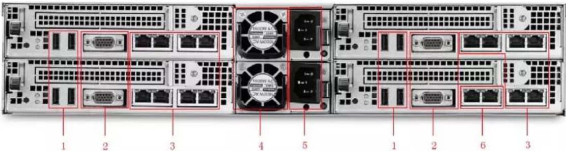
text_image
1 2 3 4 5 1 2 6 3Figure 1-4
| Serial Number | Name | Function Description |
| 1 | USB ports | Connect to mouse/keyboard. |
| 2 | VGA port | Used to connect with monitor. |
| 3 | Slave device network port | Used to connect to a network. Refer to “3.3 Quick Guide” for further details. NoteDefault IP address for the left port in each group: 192.168.1.108.Default IP address for the right port in each group: 192.168.2.108. NoteDefault IP address for the left port in each group: 192.168.1.108.Default IP address for the right port in each group: 192.168.2.108. |
| 4 | Fan | Heat dissipation. |
| 5 | Power port | Connects to 220V AC power source. |
| 6 | Master device network port | Used to connect to a network. Refer to “3.3 Quick Guide” for further details. NoteDefault IP address for the left port in each group: 192.168.1.108.Default IP address for the right port in each group: 192.168.2.108. NoteDefault IP address for the left port in each group: 192.168.1.108.Default IP address for the right port in each group: 192.168.2.108. |
Table 1-4

Note
Expansion boards can be removed and replaced.
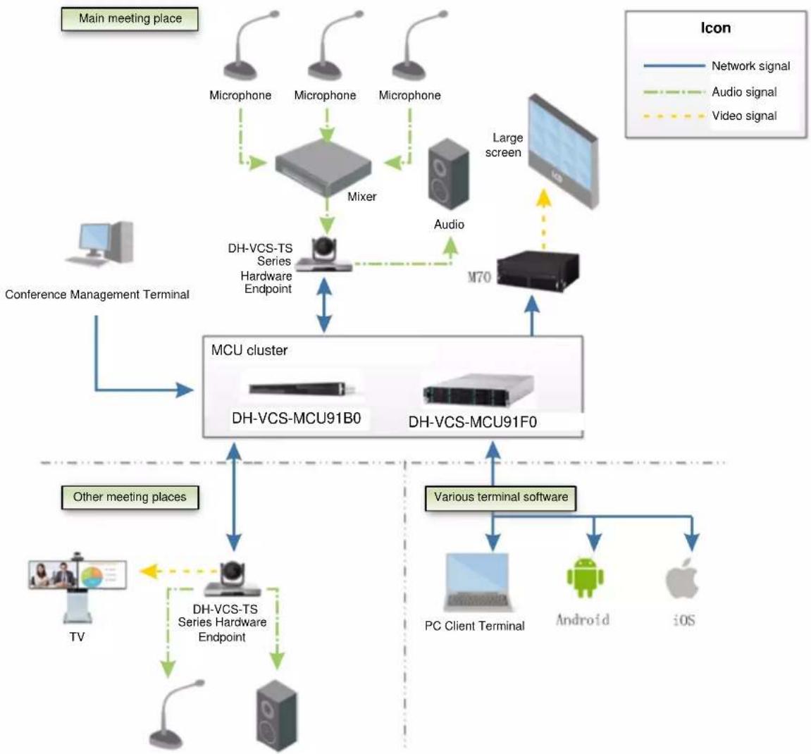
2 Networking Diagram
The networking diagram for the MCU91XX series is shown in Figure 2-1
flowchart
graph TD
    A["Main meeting place"] --> B["Microphone"]
    A --> C["Mixer"]
    A --> D["Large screen"]
    B --> E["Microphone"]
    C --> F["Audio"]
    D --> G["MD70"]
    H["Conference Management Terminal"] --> I["MCU cluster"]
    I --> J["DH-VCS-MCU91B0"]
    I --> K["DH-VCS-MCU91F0"]
    L["Other meeting places"] --> M["TV"]
    M --> N["DH-VCS-TS Series Hardware Endpoint"]
    N --> O["PC Client Terminal"]
    N --> P["Android"]
    N --> Q["iOS"]
    R["Various terminal software"] --> K
    style A fill:#f9f,stroke:#333
    style H fill:#ccf,stroke:#333
    style L fill:#cfc,stroke:#333
    style R fill:#fcc,stroke:#333
Figure 2-1
The web client terminal system provides meeting creation, current meeting, reserved meeting, meeting history, regular meetings, device management, system configuration, and other functions.
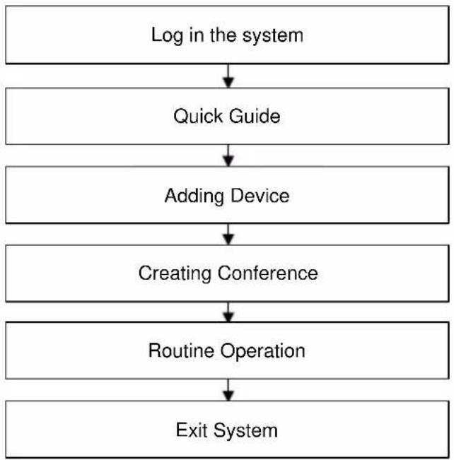
3.1 Config Flow
You can refer to the following config flow to complete the interface operation of video conferencing management system, which is shown in Figure 3-1.
flowchart
graph TD
    A["Log in the system"] --> B["Quick Guide"]
    B --> C["Adding Device"]
    C --> D["Creating Conference"]
    D --> E["Routine Operation"]
    E --> F["Exit System"]
Figure 3-1
3.2 System Login
Step 1
Enter the default "master device IP address" of video conferencing system in the IE address bar, then press [Enter].

Note
● Default IP address for the left port in each group: 192.168.1.108.
- Default IP address for the right port in each group: 192.168.2.108.
The system will display the login interface shown in Figure 3-2.

text_image
VCS Login admin Login Recommended BrowserFigure 3-2
Step 2
Enter "User Name" and "Password"
The default user name is "admin" and the default password is "12345678".
Step 3
Click "Login".
- The system will display the booting wizard interface if it is the first time to log in the system. Please refer to "3.3 Quick Guide" for more details.
- It will directly enter the main interface if you log in the system next time.
Note
- If a password has already been modified in the startup wizard, use the new password to log in.
- You can go to "System Config > User" interface to select the user which needs to be modified, click to modify the password.
3.3 Quick Guide

Caution
The quick guide only appears when logging in the system for the first time.
You can refer to the quick guide to quickly familiarize yourself with the system process if this is your first time using the system or if you are unfamiliar with the system,
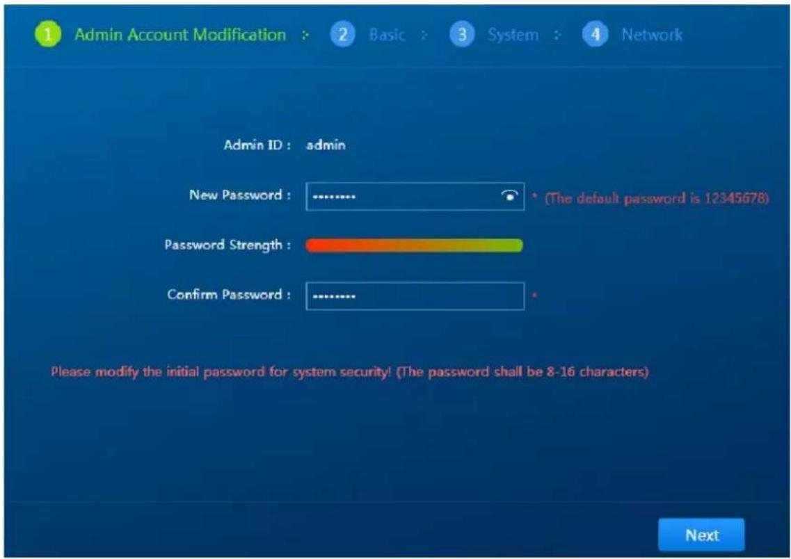
Step 1
Log in the system for the first time. The system will display the interface which is shown in Figure 3-3.
Modify the initial password of the admin account. Input "New Password" and "Confirm Password".
text_image
Admin Account Modification : 2 Basic : 3 System : 4 Network Admin ID : admin New Password : ............ (The default password is 12345678) Password Strength : Confirm Password : ............ Please modify the initial password for system security! (The password shall be 8-16 characters) NextFigure 3-3
Step 2
Click "Next" and then the system will display the interface which is shown in Figure 3-4. For basic setting, you can select "Manual Sync", "NTP Time Sync" and select "Time Zone".
Note
- As for manual sync, you can input sync time into the box of time.
- When you select "NTP Time Sync", you can input the IP address of NTP server into the box of "NTP Server".

text_image
1 Admin Account Modification > 2 Basic > 3 System > 4 Network Manual Sync : Time : 2017-03-23 13:55:41 NTP Time Sync : NTP Server : 127.0.0.1 Time Zone : (GMT+08) Beijing, Chongqing, Hong Kong, Urumchi, Kuala Lumpur... NextFigure 3-4
Step 3
Click "Next". The system will display the interface which is shown in Figure 3-5.
For system setup, you can bind the administrator with binding phone number and Email.

text_image
1 Admin Account Modification > 2 Basic 3 System 4 Network Bind Phone Number : Bind Email : Previous NextFigure 3-5
Step 4
Click "Next". The system will display the interface which is shown in Figure 3-6.

Figure 3-6
It is to set the parameters of system network.
Note
All endpoints shall be connected to the master device.
- Connect the network cable directly to the network port of master device to configure network.
1. Please refer to Table 3-1 for the configuration of network parameters.
| Parameter | Note | |
| System Network Parameter Setting | Network config | Default LAN port. |
| Network card | Here you can select which network card you need to configure master or slave IP address. | |
| IP address | Enter the pre-determined IP address (e.g. 172.10.3.148), then configure the relevant “subnet mask” and “default gateway” for the IP address. | |
| Subnet mask | ||
| Default gateway | ||
| Preferred DNS server | We recommend keeping the default DNS server IP address. If you configure a DNS server in the network, modify the DNS server IP address. | |
| Alternate DNS server | ||
| Conference Network Parameter Setting | Meeting network config | SIP (Session Initial Protocol), which is used to create, modify and release the dialog of one or several participants. |
| SIP local monitoring port | It is 50060 by default. | |
| System Service Parameter Setting | Media server address | The default address is 127.0.0.1; the local machine is used as a media server.Please input the server address here if you are using the exclusive video media server. |
Table 3-1
- Click "Complete" to finish the setting of booting wizard.
- Connect the network cable directly to the network port of slave device to configure the slave network.
- Input "Slave Device Default IP Address" into the IE address bar and press [Enter]. The system will enter the network setup interface, which is shown in Figure 3-7.
Figure 3-7
- In the setting of system network parameter, input the IP address planned for slave config which is slave IP (such as 192.168.1.100).
- In the setting of system server parameter, input host IP address in the blank of "MCU Server Address (such as 192.168.1.108).
- Click "Complete" to finish the setting of slave config network.
3.4 Device Management
3.4.1 Adding Devices
The video conferencing management system supports adding both soft endpoints and hard endpoints devices.
● Hard endpoint: TS series devices.
- Soft endpoint: mobile conferencing endpoint and PC conferencing endpoint. The client software needs to be applied separately.
The specific operation steps are shown as follows:
Step 1
Select "Device Management > Management Devices > All Devices" and the system will display the interface which is shown in Figure 3-8.

text_image
VCS Managing Management Device Management Server Management System Quality Gateway Management Management Devices All Devices Organization License Info Video Conference (20) vpi-444(2) Device Name Device ID Device Type IP Address Organization Protocol Operation ppDevice 30081674 Soft Endpoint Video Conference ISP yrc-sxt3 30082262 Soft Endpoint yrc-text ISP Sal lat 20004583 Hard Endpoint Video Conference ISP 11 20000904 Hard Endpoint Video Conference ISP yrc-sxt2 30087642 Soft Endpoint yrc-text ISP merging.wang2 30087884 Soft Endpoint Video Conference ISP Sal lat 2 30087841 Soft Endpoint Video Conference ISP yrc-sxt1 30088470 Soft Endpoint yrc-text ISP Sal lat 1 30087486 Soft Endpoint Video Conference ISP Meagling Wang 30087681 Soft Endpoint Video Conference ISPFigure 3-8
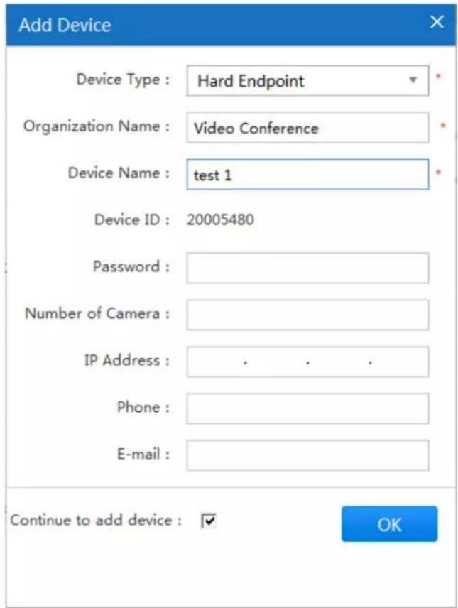
Step 2

and the system will display the interface of "Add Device", which is shown
in Figure 3-9.
text_image
Add Device Device Type : Hard Endpoint Organization Name : Video Conference Device Name : test 1 Device ID : 20005480 Password : Number of Camera : IP Address : . . . . Phone : E-mail : Continue to add device : ✓ OKFigure 3-9
Step 3
Configure parameters. Please refer to Table 3-2 for more details.
| Parameter | Note |
| Device type | Categorized as hard endpoints and soft endpoints. |
| Organization Name | The organization which the endpoint belongs to. |
| Device Name | Custom name. |
| Device ID | The device ID is automatically generated and is used as:Hard endpoints: the device ID for system registration.Soft endpoints: user name to log into PC or mobile conferencing endpoints. |
| Password | Applies to login passwords for hard and soft endpoints.NoteIf the authentication password has not yet been set, the system automatically assigns the default password: 123456. |
| Number of Cameras | Input the number of cameras, default 1 is integrated endpoint. |
| IP address | Device IP address. Enter the device IP address. By default, endpoints under this IP address can create and join conferences. |
| Phone | The phone number for the person responsible for this device. |
| The email address for the person responsible for this device. | |
| Continue to add devices | Checked: continue to add devices.Unchecked: do not continue adding devices. |
Table 3-2
Step 4
Click "OK" to finish adding devices, the system will display the interface of "All Devices", which is shown in Figure 3-10.

text_image
VCS Management Desk in All Devices Organization License Tools Video Conference (22) src boat (2) Device Name Search... Import Device Export Device Add Device Device Name Device ID Device Type IP Address Organization Protocol Operation test 1 2005480 Hard Endpoint Video Conference SIP qjaDevice 30081674 Soft Endpoint Video Conference SIP yrc-wk92 20082092 Soft Endpoint yrc-test SIP Sai Lal 20084583 Hard Endpoint Video Conference SIP 11 20090964 Hard Endpoint Video Conference SIP yrc-wk92 30095542 Soft Endpoint yrc-test SIP mengting mang2 30083584 Soft Endpoint Video Conference SIP Sai Lal 2 30087543 Soft Endpoint Video Conference SIP yrc-wk91 30088579 Soft Endpoint yrc-test SIP Sai Lal 1 30083485 Soft Endpoint Video Conference SIPFigure 3-10
- Select the device, and then click to modify the device information.
- Select the device, and then click to delete the device.
3.4.2 Modifying Device
Step 1 Select "Device Management > All Devices". The system will display the interface shown in Figure 3-11.
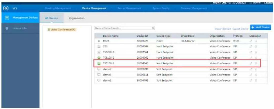
text_image
VCS Meeting Management Device Management Server Management System Config Gateway Management Management Devices All Devices Organization License Info Video Conference(9) Device Name Search... Import Device Export Device Add Device Device Name Device ID Device Type IP Address Organization Protocol Operation HS25 00000223 HS25 10.8.48.202 Video Conference HS23 222 20008004 Hard Endpoint Video Conference SIP TS5200-3 20007561 Hard Endpoint Video Conference SIP TS5100-2 20003062 Hard Endpoint Video Conference SIP TS5100-1 20004040 Hard Endpoint Video Conference SIP demo2 30003708 Soft Endpoint Video Conference SIP demo3 30003111 Soft Endpoint Video Conference SIP demo1 30009769 Soft Endpoint Video Conference SIPFigure 3-11
Step 2
Click.
The system will display the "Modify Device" interface as shown in Figure 3-12.
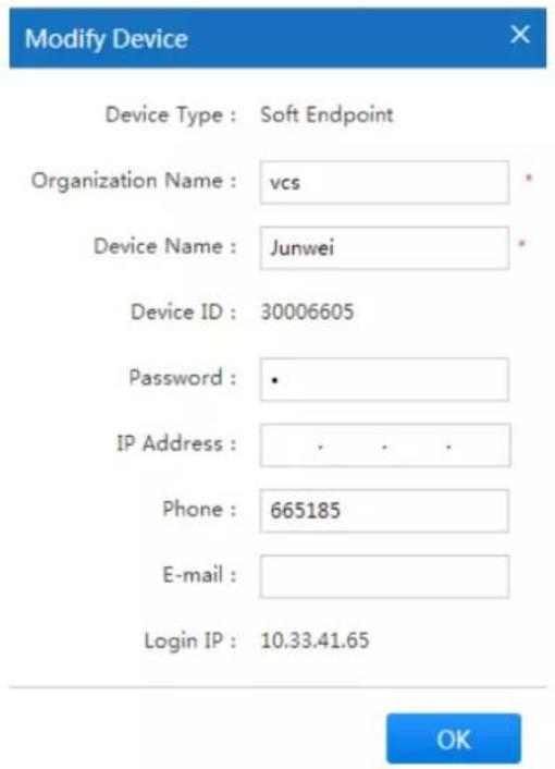
text_image
Modify Device Device Type : Soft Endpoint Organization Name : vcs Device Name : Junwei Device ID : 30006605 Password : • IP Address : . . . . Phone : 665185 E-mail : Login IP : 10.33.41.65 OKFigure 3-12
Step 3 Modify the related information of the selected device.
Step 4 Click

3.4.3 Deleting Devices
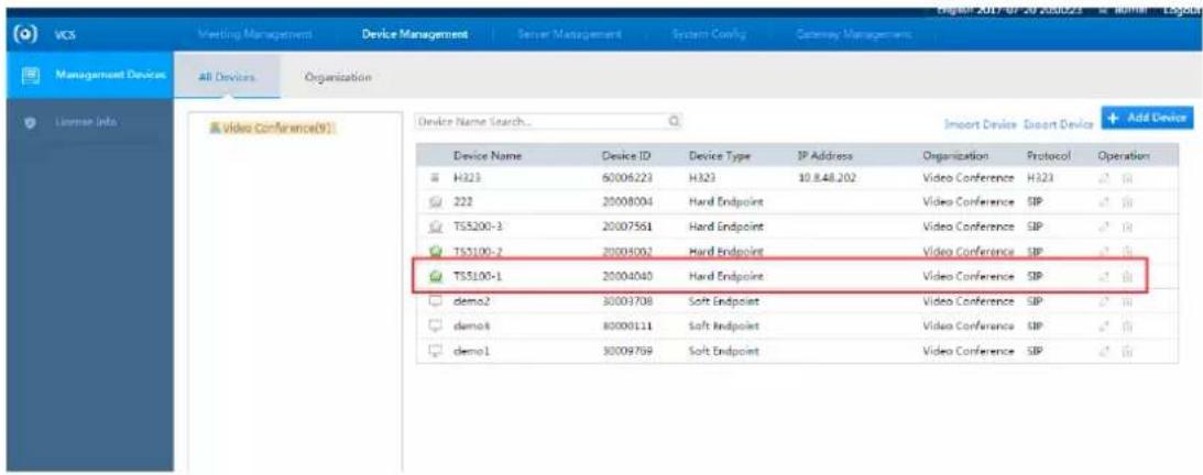
Step 1 Select "Device Management > All Devices".
The system will display the "Modify Device" interface as shown in Figure 3-13.
text_image
VCS Meeting Management Device Management Server Management System Control Gateway Management Management Devices All Devices Organization License Info Video Conference(9) Device Name Search... Import Device Export Device Add Device Device Name Device ID Device Type IP Address Organization Protocol Operation H323 6006223 H323 10.8.48.202 Video Conference H323 222 20008004 Hard Endpoint Video Conference SIP TS5200-3 20007561 Hard Endpoint Video Conference SIP TS5100-2 20005002 Hard Endpoint Video Conference SIP TS5100-1 20004040 Hard Endpoint Video Conference SIP demo2 30003708 Soft Endpoint Video Conference SIP demo3 80008111 Soft Endpoint Video Conference SIP demo1 30009769 Soft Endpoint Video Conference SIPFigure 3-13
Step 2 Click

The system will display the "Confirm Delete" interface as shown in Figure 3-14.

text_image
Please confirm Are you sure to delete the device? OK CancelFigure 3-14
Step 3 Click to confirm delete.
3.5 Service Management
3.5.1 Service Status
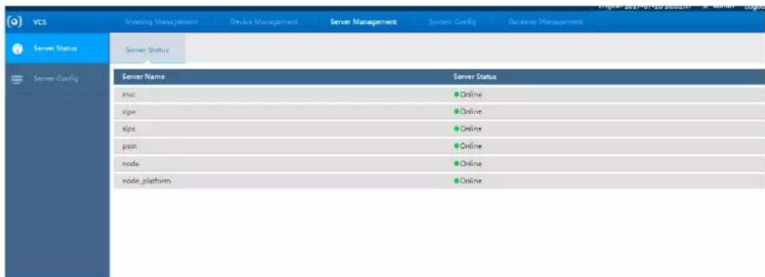
You can check the current service status of the system.
Select "Service Management > Service Status".
The system will display the interface of "Service Status", which is shown in Figure 3-15, please refer to Table 3-3 for more details about parameter description.
text_image
VCS Neeting Management Device Management Server Management System Config Gateway Management Server Status Server Status Server Name Server Status msc Online cgw Online sjps Online pstn Online node Online node_platform OnlineFigure 3-15
| Parameter | Note |
| msc | Conference media processing service, the service status is online or offline. |
| cgw | Third party device access gateway service, the service status is online or offline. |
| sips | Sip processing service, service status is online or offline. |
| pstn | Phone gateway, service status is online or offline. |
| node | Web management service, service status is online or offline. |
| node_platform | Platform cascade service, service status is online or offline. |
Table 3-3
3.5.2 Service Config
You can implement service config in this chapter.
Step 1
Select "Service Management > Service Config" and the system will display the interface of "Service Config" which is shown in Figure 3-16.

text_image
VCS Meeting Management Driver Management Server Management System Config Gateway Management Server Status Server Config Server Config Extranet IP: Multicast Segment Start: 224 - 1 - 9 - 10 Multicast Segment End: 224 - 1 - 9 - 210 OKFigure 3-16
Step 2
It is to set the IP address of Extranet.
Step 3
It is to set the network segment of multicast.
Step 4
Click to complete setting.
3.6 Conference Management
3.6.1 Creating Meeting
You can create a conference immediately or schedule a conference for the future.
- Immediate: set a conference name, duration; add participants and other information to start a conference immediately.
• Reserved: You can set a time to create a conference.

Note
- The minimum duration for a conference is 30 minutes.
• A conference can be scheduled a minute after the current time at the earliest.
Using "Reserved" as an example, the steps to start a conference are as follows:
Step 1 Select "Meeting Management" on the main interface and click to create a meeting.
The system will display the "Create" interface as shown in Figure 3-17.
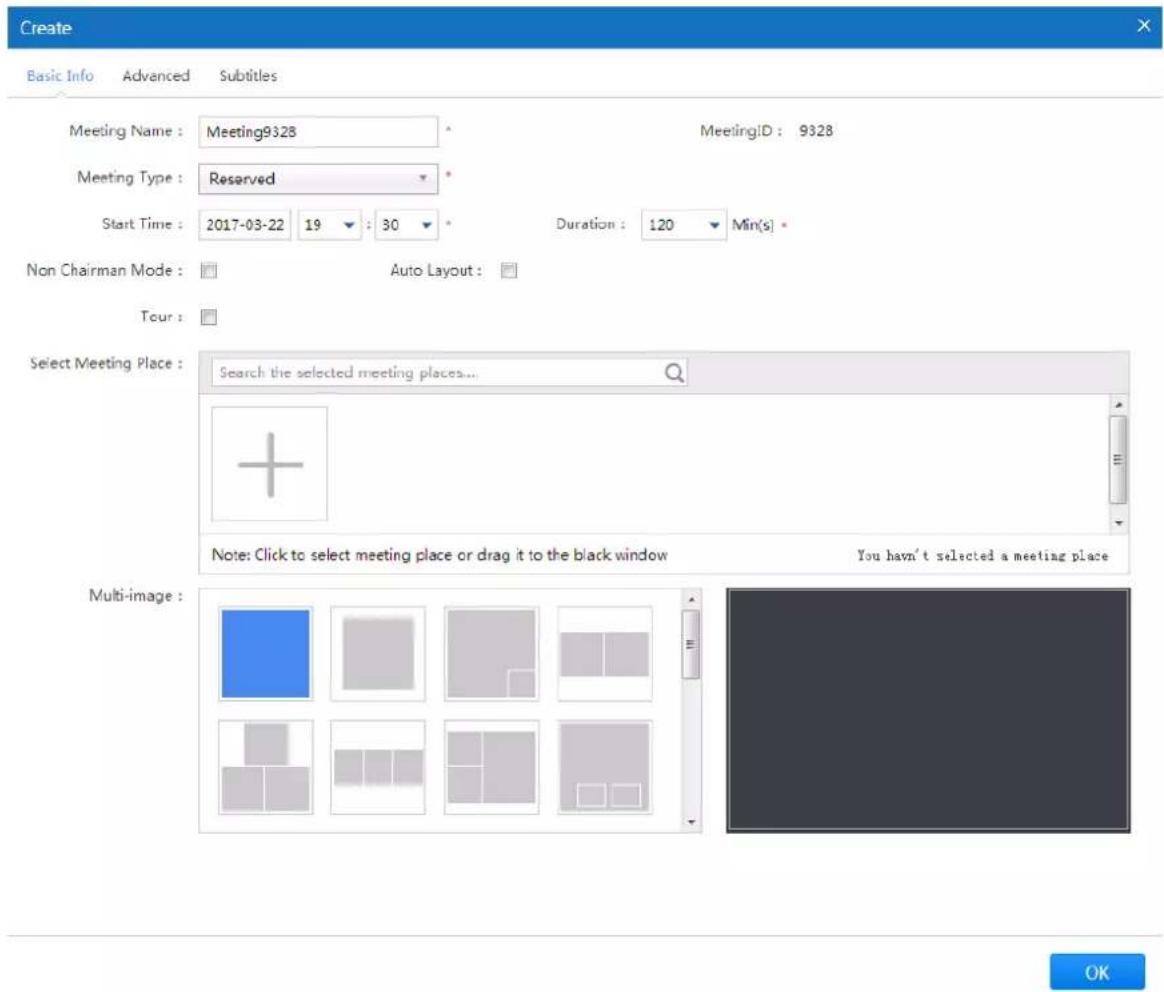
text_image
Create Basic Info Advanced Subtitles Meeting Name : Meeting9328 Meeting Type : Reserved Start Time : 2017-03-22 19 : 30 Duration : 120 Min(s) Non Chairman Mode : Auto Layout : Tour : Select Meeting Place : Search the selected meeting places... Note: Click to select meeting place or drag it to the black window You haven't selected a meeting place Multi-image :Figure 3-17
Step 2
Click "Basic Info" to set the basic info of the meeting, please refer to Table 3-4 for more details.
| Parameter | Note | |
| Basic Information | Meeting Name | Custom meeting name. |
| Meeting Type | Classified as “Immediate Meeting” or “Scheduled Meeting”. Immediate Meeting: set a meeting name, duration, meeting place and other such information, then start the meeting immediately. Scheduled Meeting: schedule a meeting time according to user requirements. | |
| Start Time | Set up the meeting start time. When “Immediate Meeting” is chosen for the “Meeting Type”, there is no need to set a start time. | |
| Duration | The duration of the meeting, the minimum is 30 minutes. | |
| Non Chairman Mode | It will create meeting in the non-chairman mode if it is selected, it can’t allocate chairman when selecting meeting place. | |
| Auto Layout | It will enable auto layout if it is selected, the multi-imagebelow can't be set. | |
| Tour | Select the check box to enable tour function among the meeting places. | |
| Select Meeting Place | Select the device which needs to join the meeting.● Input meeting name in the box, click to add meeting place.● Click and select device in the dialog box of "Add Device", click "OK" to add meeting place.● Move the mouse to the  ok it to set it as chairman if "Non Chairman Mode" is not selected, click again to cancel. ok it to set it as chairman if "Non Chairman Mode" is not selected, click again to cancel. | |
| Multi-image | You can select multiple image preview layout according to your requirements. | |
Table 3-4
Step 3
Click “Advanced” and the system will display the interface of “Advanced”, which is shown in Figure 3-18.

text_image
Create Basic Info Advanced Subtitles Join : ✓ H323 cascade to superior MCU : Meeting Password : Live : Meeting Remind : Email Remind Record : Fusion : ✓ Voice Track : Multicast : ☐ Join with Mic off : ✓ MCU Config Endpoint Config Resolution : 1080p Single Endpoint Bandwidth Limit : 2048 Kbps * FPS : 25 Resolution : 1080p Encode Format : H264BP FPS : 25 Video Bandwidth : 2048 Kbps * Encode Format : H264BP Audio Bandwidth : 64 Kbps * Audio Bandwidth : 64 Kbps * OKFigure 3-18
Step 4
It is to set the parameters of advanced, please refer to Table 3-5 for more details.
| Note | Parameter |
| Join | Select the check box and you can join meeting automatically. |
| Meeting Password | It is to set meeting password, it needs to input corresponding password if others want to join the meeting. |
| Meeting Remind | Select in the drop-down box, you can set no remind and email remind.When setting email remind, first please implement email server config in the interface of “System Config > Config > Network Service Config”. |
| Fusion | Click it to enable fusion function, and then you can set the “MCU Config” below, it can fuse a video with the video of each endpoint via MCU, which is to save bandwidth. |
| Multicast | Click it to enable multicast mode. |
| H323 cascade to superior MCU | Select the box and the meeting can be cascaded to superior MCU via H323 protocol. |
| Live | Click it to enable live, then you can make the meeting live in the recording and broadcasting system.You need to configure the IP address of RRS in “System Config > RRS Config” before enabling the function. |
| Record | Click it to enable record, then you can record and replay the meeting in the recording and broadcasting system.You need to configure the IP address of RRS in “System Config > RRS Config” before enabling the function. |
| Voice Track | Click it to enable the function.The meeting place with loudest voice of participant will be displayed in the big image if it is set in the meeting layout.The meeting place with loudest voice of participant will be displayed in the first image if the big image is not set in the meeting layout. |
| Join with Mic off | Click the box and the participants will join the meeting in the form of Mic off. |
| MCU Config | When fusion function is enabled, it can set the image resolution PFS, encode format, video bandwidth and audio bandwidth after fusion.Resolution, it can select standard definition, high definition and ultra-high definition, such as 720P, 1080P and 2160P.FPS, the frame rate of fusion stream shall be set in accordance with that of the endpoint device, select 25 FPS.Encoding format, H264HP, H264BP and H265 optional.Video bandwidth, select video transmission bandwidth according to the actual situation.Audio bandwidth, select audio transmission bandwidth according to the actual situation. |
| Endpoint Config | It is to set the image parameter when sending video to each endpoint.If fusion is enabled, then it will send one channel video signal which has been fused to endpoint according to the configured parameters.If fusion is not enabled, it will send each video signal of all meeting places to each endpoint according to the “Single Endpoint Bandwidth Limit” which has been set.“Single Endpoint Bandwidth Limit”, it can be set according to the actual bandwidth, refer to MCU config for other parameters. |
Table 3-5
Step 5
Click "Subtitles" and the system will display the interface of "Subtitles", which is shown in Figure 3-19
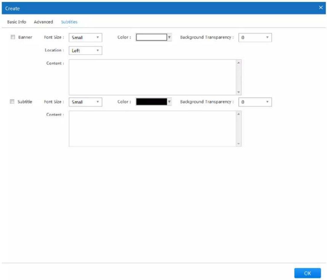
text_image
Create Basic Info Advanced Subtitles Banner Font Size : Small Color : Background Transparency : 0 Location : Left Content : Subtitle Font Size : Small Color : Background Transparency : 0 Content :Figure 3-19
Step 6
Set "Banner" and "Subtitles".
- Banner, it is displayed on the top of the screen; you can adjust display location, font size, color and background transparency according to requirements.
- Subtitles, it is scrolling displayed on the bottom of the screen, you can adjust font size, color and background transparency according to requirements.
Step 7
Click "OK" to finish creating meeting, you can check on the interface of "System Setting > Meeting Management > Current Meeting".
3.6.2 Meeting Control
Select the interface of "Meeting Management > Current Meeting" and the system will display the interface of "Current Meeting", which is shown in Figure 3-20.
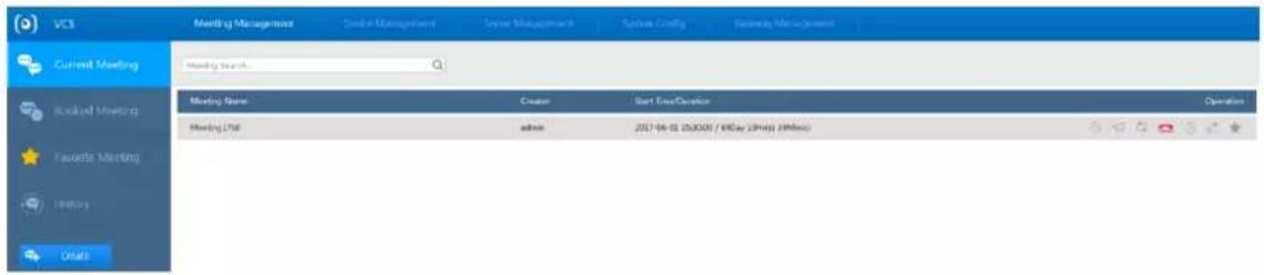
text_image
UCS Meeting Management Session Management Session Config Security Management Current Meeting Meeting Search Meeting Name Creator Start Time/Duration Operation Meeting URL admin 2017-04-18 15:00:00 / 90 Day (3 PM) (9 MHz) Favorite Meeting History DraftFigure 3-20
| Icon | Note |
| [000C] | Click it to check the report of meeting quality. |
 | Click it to set broadcast info, it will disappear automatically after it is displayed and reminded on the endpoint screen. |
 | Click it to set roll call tour. It can make roll call upon each meeting place according to the “Tour Interval” which has been set.NoteOnly after the chairman is set, the chairman has authority to use the function. |
 | Click it to end meeting. |
 | Click it to modify meeting end time. |
 | Click it to modify meeting info. |
 | Click it to add it as regular meeting, you can check on the interface of “Meeting Management > Favorite Meeting”. |
Table 3-6
Click the selected meeting to check the detailed info of the meeting, which is shown in Figure 3-21.

text_image
Meeting3703 admin 2017-06-02 09:53:00 / 2Hr(x) MeetingID : 3703 Single Endpoint Bandwidth Limit : 2048 Meeting Status : Enabled Meeting Password : No Password Duration : 2Hr(x) Join : Yes Meeting Remind : Email Remind Recording Status : Unrecorded Meeting Attendance List General Display | Send Substream to All | Mainstream Image | Chairman Image | All Mic Disabled | All Speakers Disabled LY Audio : 0k/s 0k/s Video : 0k/s 0k/s Junwoi Audio : 0k/s 0k/s Uplink Bandwidth Sufficient Video : 80k/s 581k/s Downlink Bandwidth Sufficient chen_xiaoka_ Audio : 0k/s 0k/s Video : 0k/s 0k/s testgao Audio : 0k/s 0k/s Video : 0k/s 0k/sFigure 3-21
| Icon | Note |
| ☐ | All Mic Disabled | Click it to disable Mic for all the members. |
☐ | All Speakers Disabled | Click it to make it mute for all meeting members.Click the icon to apply for and cancel chairman. ., it means chairman. ., it means chairman. ., it means non-chairman. ., it means non-chairman. |
 | Click the icon to select fusion stream of the endpoint image switch image of other participants and the image layout displayed on the endpoint.● Image select, it is to select fusion stream according to the actual network situation, click “OK” to make it valid.● Layout setting, it is to select the needed layout, click “OK” to make it valid. |
 | Click the icon to preview endpoint video, adjust endpoint image, resolution, and total bandwidth etc. You can select the meeting place which needs to be adjusted in the “Meeting Place List”. |
 | Click the icon to switch if it is to display demo image. |
 | Click the icon and the chairman can make roll call of the meeting participants, both chairman and meeting participant can see the image of opposite side, but it fails to see his own image. |
 | Click the icon to control the video signal of the meeting place.● Blue means that it can see the image of the meeting place.● Gray means that it fails to see the image of meeting place. |
 | Click the icon to control if it is to disable mic.● Blue means that mic is enabled.● Gray means that mic is disabled. |
 | Click the icon to control if it is to make the meeting place mute.● Blue means that it can hear the voice of the meeting place.● Gray means that the meeting place is mute. |
 | Click the icon to hang up and ask meeting participant to leave. |
 | Click the icon to invite the participant to join the meeting. |
Table 3-7
3.6.3 Booked Meetings
Select "Meeting Management > Booked Meeting" and the system will display the interface of "Booked Meeting", which is shown in Figure 3-22.
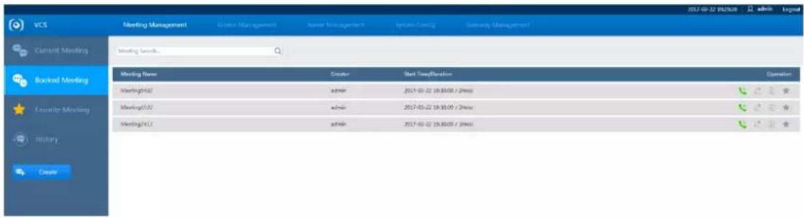
text_image
VCS Meeting Management Current Meeting Meeting Settings Meeting Name Creator Start Time/Duration Operation Meeting142 admin 2017-01-22 19:30:00 / 2h:00 Meeting142 admin 2017-01-22 19:30:00 / 2h:00 Meeting142 admin 2017-01-22 19:30:00 / 2h:00Figure 3-22
| Parameter | Description |
 | Click this icon to start the meeting immediately. |
 | Click this icon to edit meeting information. |
 | Click this icon to cancel the booked meeting. |
 | Click this icon to add to favorite meetings. You can view details on the “System Configuration > Meeting Management > Favorite Meeting” interface. |
Table 3-8

Note
Enter the "Meeting Name" into the search bar for a quick search.
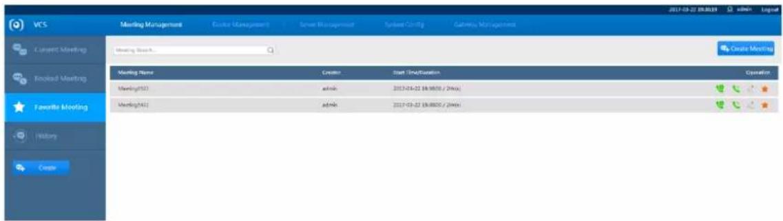
3.6.4 Favorite Meetings
Select "Meeting Management > Favorite Meeting".
The system will display the "Favorite Meeting" interface which is shown in Figure 3-23.
text_image
VCS Meeting Management Create Manager? Smart Manager System Config Gathering Management 2017-03-27 09:00:19 LinkedIn Layout Current Meeting Meeting Search Create Meeting Meeting Name Creator Start Time/Duration Operation Meeting(13) admin 2017-03-22 18:00:1 / 24hex Meeting(43) admin 2017-03-22 18:00:1 / 24hex Favorite Meeting History CreateFigure 3-23
| Parameter | Description |
 | Click this icon to start a meeting. |
 | Click this icon to hold the meeting immediately. |
 | Click this icon to edit meeting information. |
| Click this icon to delete the meeting from favorites. |

Note
Enter the "Meeting Name" into the search bar for a quick search.
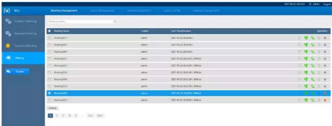
3.6.5 Meeting History
Select "System Configuration > Meeting Management > History".
The system will display the "History" interface which is shown in Figure 3-24.
text_image
VCS Meeting Management Course Management Session Management System Settings Language Management Meeting List... Meeting Name Create Start Group/Duration Operation Meeting17 admin 2017-03-22 19:02:09 / Meeting18 admin 2017-03-22 19:02:09 / Meeting204 admin 2017-03-22 19:02:09 / Meeting217 admin 2017-03-22 19:01:09 / 1MHz/uc Meeting221 admin 2017-03-22 19:01:09 / 1MHz/uc Meeting234 admin 2017-03-22 19:01:09 / 1MHz/uc Meeting248 admin 2017-03-22 19:01:09 / 1MHz/uc Meeting255 admin 2017-03-22 19:01:09 / 1MHz/uc Meeting261 admin 2017-03-22 19:00:09 / 1MHz/uc Meeting271 admin 2017-03-22 19:00:09 / 1MHz/uc DeleteFigure 3-24
| Parameter | Description | |
 | Click to create a meeting. Refer to “3.6.1Creating Meeting” for further details. | |
 | Click to start the meeting immediately. | |
 | Click to delete the meeting. | |
 | Click to delete the meeting from favorites. | |
Table 3-9
3.7 System Management
3.7.1 User Management
You can create and delete users. The administrator can edit all users' rights and administrative Privileges including his own. Different users can be allocated different privileges, which are shown in Figure 3-25.
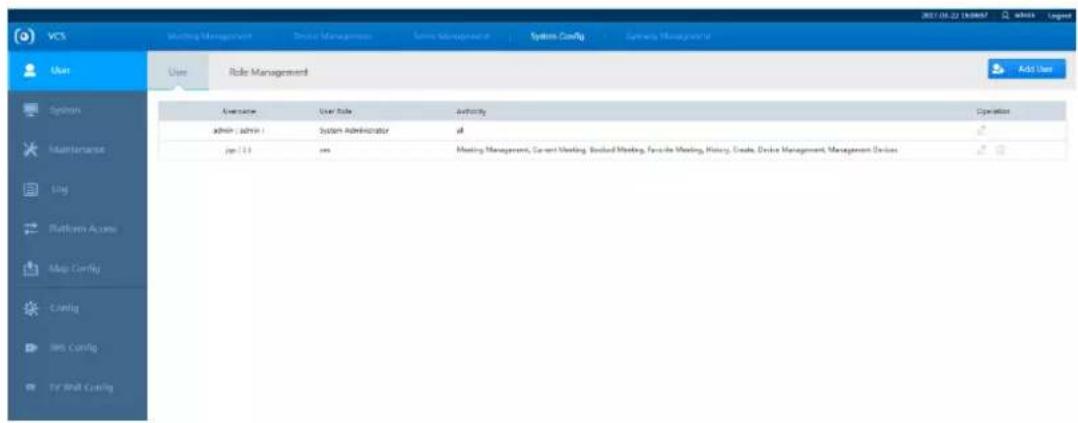
text_image
VCS User Role Management Add User Overview User Role Authority Operation admin (admin) System Administrator all jan 13 yes Meeting Management, Current Meeting, Second Meeting, Favorite Meeting, History, Grade, Device Management, Management DevicesFigure 3-25
3.7.1.1 Adding Users
Step 1
Click Add User in "System Configuration > System > User" and the system will display the interface of "Add User", which is shown in Figure 3-26.
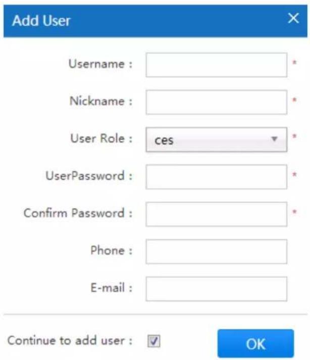
text_image
Add User Username : Nickname : User Role : ces * UserPassword : Confirm Password : Phone : E-mail : Continue to add user : ✓ OKFigure 3-26
Step 2
Set the user name, nickname, user role, user password, and other relevant information.

Note
You can continue to add users by checking “Continue to add user”. If you do not select the option, the system will exit the “Add User” interface after adding the user.
| Parameter | Description |
| System Administrator | It has meeting, device, user, operation and maintenance, system settings, and other management privileges. |
| Conference Administrator | It has conference, device, and user management privileges. |
Table 3-10
Step 3
OK Click to complete
3.7.1.2 Modifying User Accounts
Step 1
Click in "System Configuration > User" and the system will display the interface of "Modify User", which is shown in Figure 3-27.
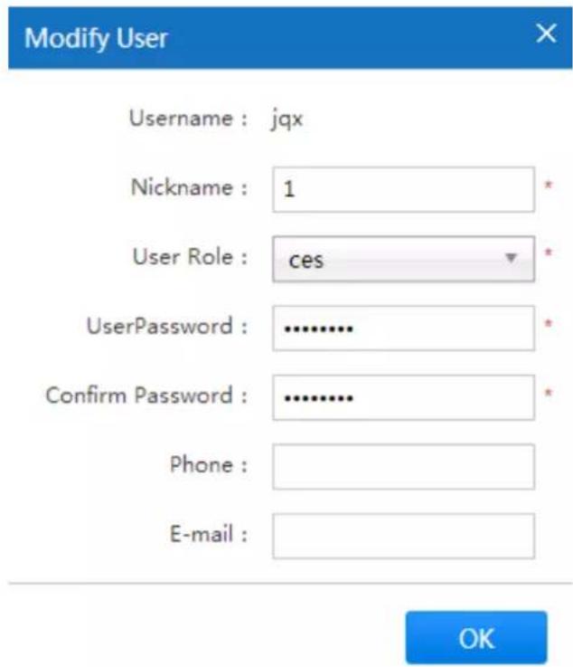
text_image
Modify User Username : jqx Nickname : 1 * User Role : ces * UserPassword : .......... Confirm Password : .......... Phone : E-mail : OKFigure 3-27
Step 2
It is to set the nickname, password, user role and other relevant information of the user which has been selected by you.
Step 3
Click after setting is completed to save modifications.
3.7.1.3 Deleting Users
Step 1
Select "System Configuration > User" and the system will display the interface which is shown in Figure 3-28.
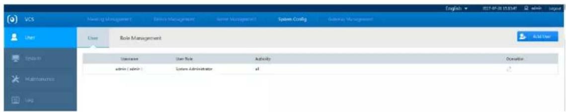
text_image
VCS User User Role Management User Role admin ( admin ) System Administrator Authority All Operation English - 2017-05-28 15:54:47 admin - logo Add UserFigure 3-28
Step 2
Click and the system will display the interface of "Delete", which is shown in Figure 3-29.

text_image
Please confirm Are you sure to delete the user? OK CancelFigure 3-29
Step 3
Click OK to confirm delete.
3.7.2 System Management
3.7.2.1 System Status
Step 1
Go to "System Configuration > System > System Status".
The system will display the interface of "System Status", which is shown in Figure 3-30.
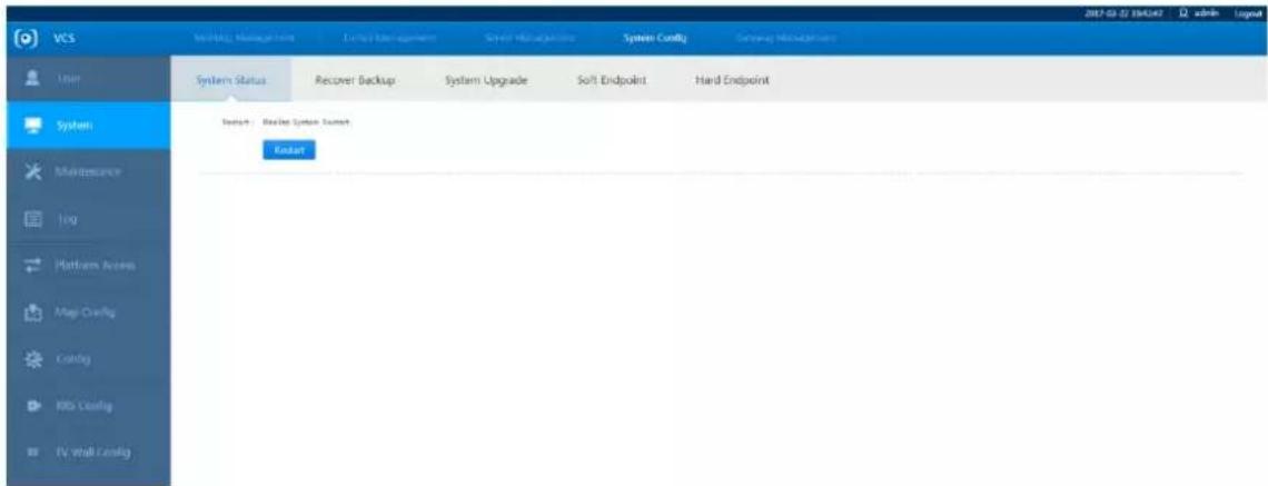
text_image
VCS System Status: Recover Backup System Upgrade Soft Endpoint Hard Endpoint System Maintenance Log Platform Access Map Config Config RIO Config IV wall Config EndsetFigure 3-30
Step 2
Click and the system will restart.
3.7.2.2 Backup Recovery
Select "System Configuration > System > Recover Backup" and the system will display the interface which is shown in Figure 3-31.
- Backup Export: Click to select the path for the backup location. This will back up all the configuration data from the web client.

Caution
Incorrect import will cause the system to be unrecoverable.
- Import backup: Click to select the backup file you want to import and recover the backed up data.

text_image
VCS Meeting Manager Circuit Management Smart Management System Config Gateway Management System Status Resource Backup System Upgrade Soft Endpoint Hard Endpoint Backup Export: Report and backup of the current config Backup Export Backup Import: Import config file to recover system config Select File: Choose File: No file chosen Backup ImportFigure 3-31
3.7.2.3 System Upgrade

Caution
Incorrect system upgrade may lead to the system not functioning properly.
During firmware upgrade, select the upgrade file to import and perform the upgrade. The update file will have a .bin extension. During the upgrade process, do not disconnect the power or network connection, reset, or shutdown the device.
Step 1
Select "System Config > System > System Upgrade".
The system will display the interface of "System Upgrade", which is shown in Figure 3-32.

text_image
VCS Routing Management | Drive Management | Serve Management | System Config | Gateway Management User System Status Recover Backup System Upgrade Soft Endpoint Hard Endpoint Version Info Machine Code Softacid09Afs4505215 Release Data Version No. 1.0.0.4753 System Upgrade Upload File Choose File No file chosen OK Advice Use 360 browser to check file upload progress System Maintenance Log Platform Access Map Config Config RRS Config TV Wall ConfigFigure 3-32
Step 2
Click "Browse" and select the update file on the local system. The update file will have a .bin extension.
Step 3
Click to begin t
3.7.2.4 Soft Endpoint
It can realize software version upgrade via uploading and downloading soft endpoint installation file.
3.7.2.4.1 Soft Endpoint Downloads
Step 1
Select "System Configuration > System > Soft Endpoint".
The system will display the "Soft Endpoint" interface as shown in Figure 3-33.
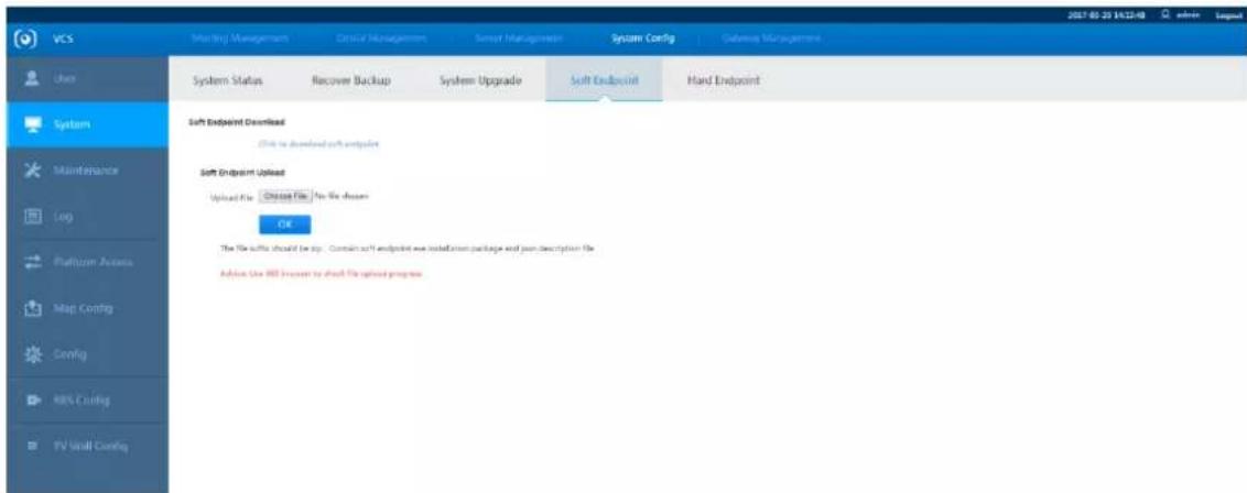
text_image
VCS Matching Management Critical Management Sensed Management System Config Guidance Management System Status Recover Backup System Upgrade Soft Endpoint Hard Endpoint Soft Endpoint Download Click to download soft endpoint Soft Endpoint Upload Upload File Choose File No file chosen OK The file defaults should be any. Contains soft endpoint with installation package and join description file. Advice Use HBD server to share file upload processFigure 3-33
Step 2
Click "Click to download soft endpoint" and the system will display the interface of "File Download".
Step 3
Click "Save" and select the download path.
The system will display the "Save As" interface.
Step 4
Click "Save" to start download.
3.7.2.4.2 Soft Endpoint Upload
Step 1
Select "System Configuration > System > Soft Endpoint".
The system will display the "Soft Endpoint" interface.
Step 2
Click "Browse".
The system will display the "Select File to Upload" interface.
Step 3
Select the upload file from the local system.
Step 4
Click "Open" and the system will display the "Soft Endpoint" interface which is shown in Figure 3-34.

text_image
VCS Meeting Management Device Management Service Management System Config Gateway Management User System Status System Upgrade Soft Endpoint Hard Endpoint System Soft Endpoint Download Click to download soft endpoint Maintenance Soft Endpoint Upload Upload File Select File No file chosen OK The file suffix should be slip, The file suffix should be slip, which contains Advice: Use 180 browser to check file upload progress Platform Access Config TV Wall ConfigFigure 3-34
Step 5
Click "OK" to start upload.
3.7.2.5 Hard Endpoint
It can realize program upgrade via uploading and downloading hard endpoint installation file.
3.7.2.5.1 Hard Endpoint Download
Step 1
Select "System Configuration > System > Hard Endpoint".
The system will display the interface of "Hard Endpoint".
Step 2
Select actual hard endpoint device model in the drop-down box of "Endpoint Model".
Step 3
Click "Click to download hard endpoint" and the system will display the interface of "File Download".
Step 4
Click "Save" and select download path.
The system will display the interface of "Save As".
Step 5
Click "Save" to start download.
3.7.2.5.2 Hard Endpoint Upload
Step 1
Select "System Configuration > System > Hard Endpoint".
The system will display the interface of "Hard Endpoint".
Step 2
Select actual hard endpoint device model in the drop-down box of "Endpoint Model", and then input version number.
Step 3
Click "Browse" and the system will display the interface of "Select file to upload".
Step 4
Select upload file in the local system.
Step 5
Click "Open".
The system will display the interface of "Hard Endpoint", which is shown in Figure 3-35.
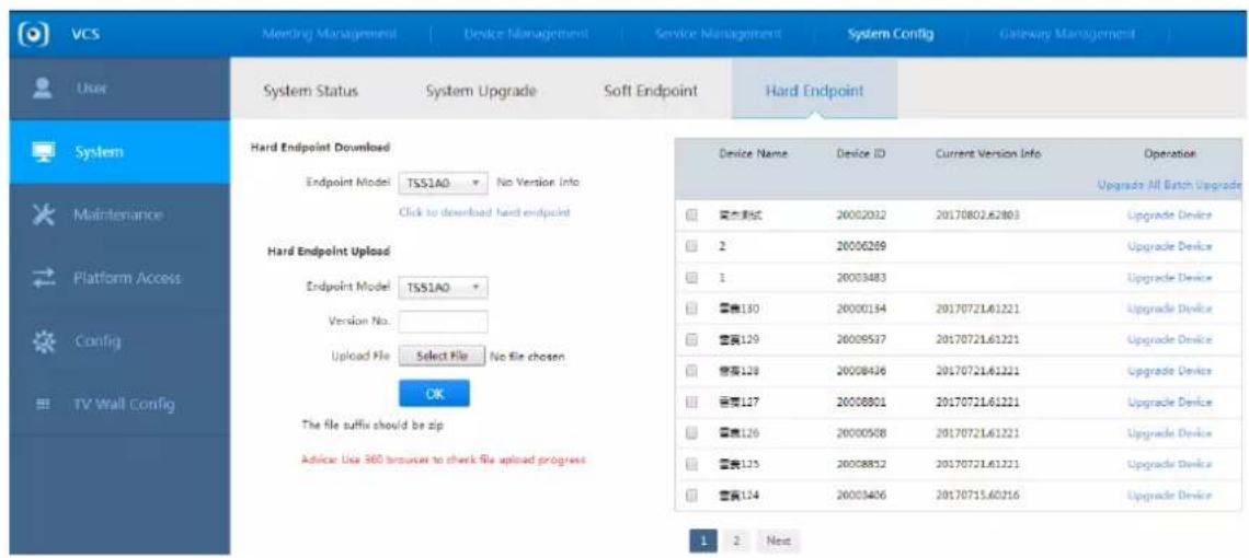
text_image
VCS Meeting Management Device Management Service Management System Config Gateway Management User System Status System Upgrade Soft Endpoint Hard Endpoint System Status System Upgrade Soft Endpoint Hard Endpoint System System Maintenance Platform Access Config TV Wall Config Hard Endpoint Download Endpoint Model TSS1AO No Version Info Click to download hard endpoint Hard Endpoint Upload Endpoint Model TSS1AO Version No. Upload File Select File No file chosen OK The file suffix should be zip Advice: Use 360 browser to check file upload progress Device Name Device ID Current Version Info Operation Upgrade All Batch Upgrade 安装调试 20002032 20170802.62803 Upgrade Device 2 20006269 Upgrade Device 1 20003483 Upgrade Device 容量130 20000194 20170721.61221 Upgrade Device 容量129 20009537 20170721.61221 Upgrade Device 容量128 20008436 20170721.61221 Upgrade Device 容量127 20008801 20170721.61221 Upgrade Device 容量126 20000568 20170721.61221 Upgrade Device 容量125 20008852 20170721.61221 Upgrade Device 容量124 20003406 20170715.60216 Upgrade Device 1 2 NextFigure 3-35
Step 6
Click "OK" to start upload.
3.7.3 Maintenance Management
3.7.3.1 Clustering and Stacking
Clustering and Stacking refers to using multiple devices to form a single cluster. When the capacity from one or more devices has been exceeded, you can manually switch to use multiple slave devices and allow them to perform the tasks of the master device.

Caution
Slave device connection and system configuration must be completed first. For further details, refer to "3.3 Quick Guide".
Step 1
Select "System Configuration > Maintenance".
The system will display the "Capacity" interface which is shown in Figure 3-36.
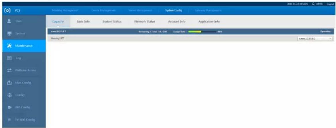
text_image
VCS Meeting Management Device Management System Management System Config Gateway Management Capacity Basic Info System Status Network Status Account Info Application Info Meeting 10.15.8.7 Routing / Total: 54 / 109 Stage Rate 80% Meeting1977 Meeting 10.15.8.7 OperationFigure 3-36
Step 2
Click and select the required meeting on the drop-down menu on the right side. Select the switching device as shown in Figure 3-37.

text_image
s.msc.10.35.8.7 Auto Allocation s.msc.10.35.8.7Figure 3-37

Note
The largest amount of resources of a single device is 70.
3.7.3.2 Basic Information
It is to display and check basic system information, memory configuration, CPU configuration, and hard disk IO status.
Select "System Configuration > Maintenance > Basic Information" and the system will display the interface which is shown in Figure 3-38.
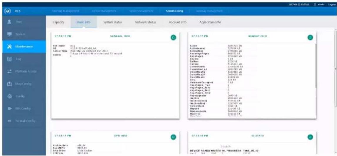
text_image
VCS Holding Management Online Management Network Management System Config Server Management Capacity Basic Info System Status Network Status Account Info Applications Info 07.04.17 PM GENERAL, INFO 07.05.17 PM MEMORY INFO Active 349710 KB ActiveText 72786 KB ActiveText 218600 KB ActivePages 840157 KB ActivePages 125940 KB Balance 0 KB Buffers 1274 KB Camera 512600 KB CommandSet 1308130 KB CommandSet_AS 262780 KB DirectPages 524280 KB DirectPages2M 240900 KB DirectPages 82438 KB Disk 134 KB Hardware/Converted 0 KB PagePages_Free 0 KB PagePages_Bord 0 KB PagePages_SATP 0 KB PagePages_Total 2049 KB Headline 290862 KB ExecutiveCode 535462 KB ExecutiveCode) 225280 KB KernelStacks 7469 KB Spread1 125480 KB HomeCaspInfoe 264402 KB HomeFree 225312 KB HomeFboxy 166331 KB ST 51-17 PM CPU INFO ST 51-18 PM ID STAT3 Architecture xDS_54 Avg-DMPS 0443 KB Beta Order Little Eastern CPU MHz 3837.939 Search DEVICE READS WRITES IN PROGRESS TIME_IN_IO Device Read's Writes IN PROGRESS TIME_IN_IOFigure 3-38
3.7.3.3 System Status
It is to display and check memory, CPU, hard disk partition, and various other usage statuses.
Select "System Configuration > Maintenance > System Status" and the system will display the interface which is shown in Figure 3-39.
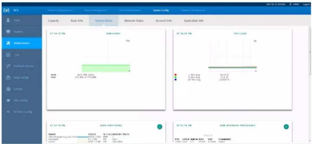
text_image
VCS Capacity Basic Info System Status Network Status Account Info Application Info 07:54:10 PM Real time/ADC 7% Used free 2673 Mbps (22%) 2.22 Mbps of 1773/MB 07:54:10 PM GPU LOAD 1 Min Avg 5 Min Avg 5 Min Avg 16.25 % 12.22 % 07:54:10 PM Disk partition/ADC NAME STALS % YULE/MOUNT PATH Data from operating system damping 0 < 2.96 % ddev Inlay -4.5% < 0.80 1% ddev/dm 07:54:10 PM RAM INTENSIVE PROCES/DES PUD USER %MEM RSS VSZ COMMAND 1992 year 9.3 1993 21/5/20 endFigure 3-39
3.7.3.4 Network Status
It is to display and check network monitoring status and network speed.
Select "System Configuration > Maintenance > Network Status". The system will display the interface
which is shown in Figure 3-40.

text_image
VCS Membership Management Capacity Basic Info System Status Network Status Account Info Application Info User System Maintenance Log Platform Access Map Config Config RMS Config TV Bus Config 07.51.18 PM IP ADDRESSS 07.51.18 PM NETWORK CONNECTIONS 07.51.18 PM INDEX 07.51.18 PM 07.51.18 PM 07.51.18 PM 07.51.18 PM 07.51.18 PM 07.51.18 PM 07.51.18 PM 07.51.18 PM 07.51.18 PM 07.51.18 PM 07.51.18PM 07.51.18PM 07.51.18PM 07.51.18PM 07.51.18PM 07.51.18PM 07.51.18PM 07.51.18PM 07.51.18PM 07.51.18PM 07.51.18PINSPEEDS 07.51.18PINSPEEDS 07.51.18PINSPEEDS 07.51.18PINSPEEDS 07.51.18PINSPEEDS 07.51.18PINSPEEDS 07.51.18PINSPEEDS 07.51.18PINSPEEDS 07.51.19PINSPEEDS 07.51.19PINSPEEDS 07.51.19PINSPEEDS 07.51.19PINSPEEDS 07.51.20PINSPEEDS 07.51.20PINSPEEDS 07.51.20PINSPEEDS 07.51.20PINSPEEDS 07.51.20PINSPEEDS 07.51.20PINSPEEDS 07.51.20PINSPEEDS 07.51.20PINSPEEDS 07.63 63 64 65 66 67 68 69 70 71 72 73 74 75 76 77 78 79 80 81 82 83 84 85 86 87 88 89 90 91 92 93 94 95 96 97 98 99 100 101 102 103 104 105 106 107 108 109 110 111 112 113 114 115 116 117 118 119 120 121 122 123 124 125 126 127 128 129 130 131 132 133 134 135 136 137 138 139 140 141 142 143 144 145 146 147 148 149 150 151 152 153 154 155 156 157 158 159 160 161 162 163 164 165 166 167 168 169 170 171 172 173 174 175 176 177 178 179 180 181 182 183 184 185 186 187 188 189 200Figure 3-40
3.7.3.5 Account Information
It is to display information about system back-end accounts, logged in accounts, and recent logins Select "System Configuration > Maintenance > Account Information". The system will display the interface which is shown in Figure 3-41.

text_image
VCS Status Management System Management System Management System Config System Management Capacity Basic Info System Status Network Status Account Info Application Info 87.51.17 PM ACCOUNTS 87.51.17 PM LOGGED IN ACCOUNTS TYPE: USER HOME user: appfile user: $_bachang user: topcump user: root user: submand user: driver user: colland user: ipc user: childress user: game user: mail user: tbid user: games user: pulse user: nobody user: emailand user: dlua user: pingxnt user: pingxnt user: pcnset user: pcnset@ngmt user: pcnsetbody user: pcp LOGED IN ACCOUNTS USER FROM root root root root root root root root root root root root root root root root root root root root root root root root root root root root root root root root root root root root root root root root root root root root root root root root root root user: logged in accounts LOGED IN ACCOUNTSFigure 3-41
3.7.3.6 Application Information
Select "System Configuration > Maintenance > Application Information". The system will display the interface which is shown in Figure 3-42.

text_image
VCS Meeting Management System Management System Config Database Management Capacity Basic Info System Status Network Status Account Info Application Info Maintenance 07.51.12 PM COMMON APPLICATIONS Search MINARY LOCATION INSTALLED output index tree specify index tree only index tree type (type/Python /user/Info/Python) 3.7 type (user/Python) 2.7 /user/Info/Python 2.7 /user/when system (user/Python) 2.7 /user/when energy bin tree mysql /user/Info/when /user/share/when php node tree 2007-02-27 19:56:58 admin EngineFigure 3-42
3.7.4 Platform Access
It can display log according to time range, which makes it convenient for users to check and export.
Step 1
Select "System Config > Platform Access". The system will display the interface of "Platform Access", which is shown in Figure 3-43.

text_image
VCS Meeting Manager Direct Manager Select Manager System Config Gateway Manager Add Platform Platform Search Platform Name Platform Type Platform IP Platform Port Platform Status Operation 183 MCU 10.25.6.181 80 Online Platform Access Config TV Wall ConfigFigure 3-43
Step 2

and the system will display the interface of "Add Platform", which is shown
in Figure 3-44.
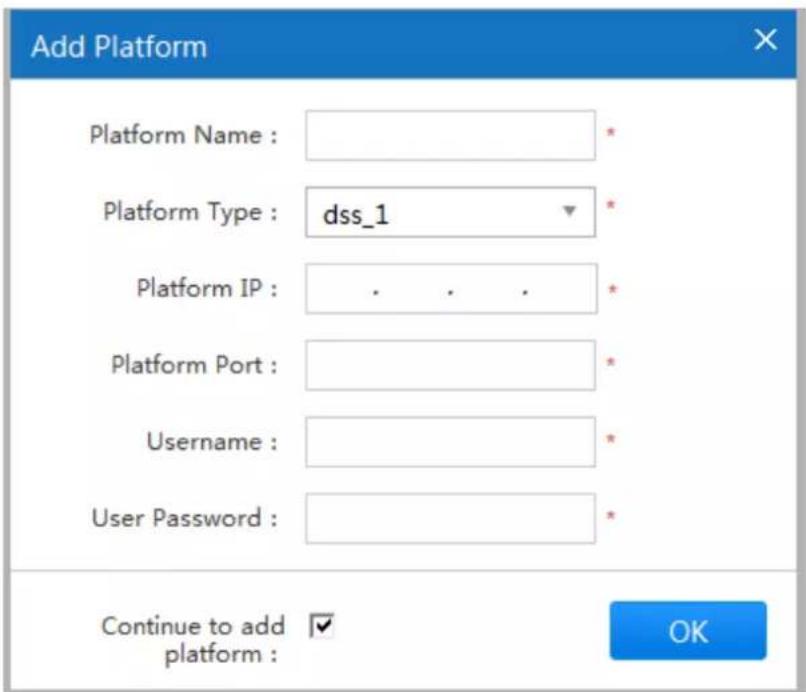
text_image
Add Platform Platform Name : Platform Type : dss_1 Platform IP : . . . * Platform Port : Username : User Password : Continue to add ✓ platform : OKFigure 3-44
Step 3
It is to configure parameters, please refer to Table 3-11 for more details about parameters.
| Parameter | Note |
| Platform Name | Customized platform name. |
| Platform Type | dss_1 type by default. |
| Platform IP | Set IP address of added platform. |
| Platform Port | Set port number of the platform. |
| Username | User and password of the connected platform. |
| Password | |
| Continue to add device | Selected: continue to add device.Unselected: do not continue to add device. |
Table 3-11
Step 4
OK Click to complete adding.
Note
- Click to modify the platform information.
- Click to delete the platform.
3.7.5 Config
3.7.5.1 Local Setting
You can set or modify local basic parameters on this interface if you haven't made settings in the boot wizard.
Step 1
Select "System Config > Config > Local Setting" and the system will display the interface of "Local Setting", which is shown in Figure 3-45.
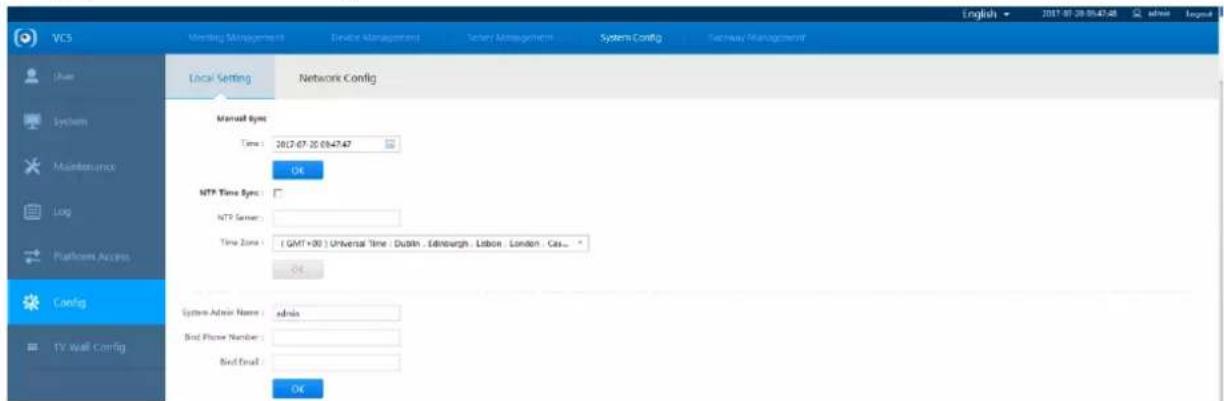
text_image
VCS Membership Management Revise Management Service Management System Config Technology Management Local Setting Network Config Manual Sys: Time : 2017-07-20 09:47:47 OK MTP Time Sys : MTP Server : Time Zone : ( GMT+30 ) Universal Time : Dublin , Edinburgh , Lisbon , London , Cas... OK System Admin Name : admin Bird Phone Number : Bird Email : OK System Admin Name : admin Bird Phone Number : Bird Email :Figure 3-45
Step 2
It can make settings of time sync mode, admin name and account binding according to the actual requirements of users.
Step 3
Click

3.7.5.2 Network Config
You can set network config on this interface if you haven't set it in the chapter of boot wizard.
Step 1
Select "System Config > Config > Network Config" and the system will display the interface of 'Network Config', which is shown in Figure 3-46.
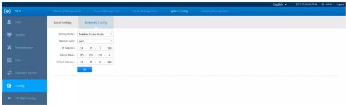
text_image
VCS Meeting Management Device Management Server Management System Config Session Management Local Setting Network Config Binding Mode: Multiple Access Mode Network Card: ex61 IP Address: 10 - 35 - 8 - 180 Select Mask: 255 - 259 - 252 - 8 Default Gateway: 16 - 85 - 14 - 214 OK System Manufacture Log Parameters Access Config Yr Wall Config English 2017-07-20 06:32:43 admin LegendFigure 3-46
| Parameter | Note |
| Binding Mode | Select multiple access mode. |
| Network Card | Select the needed network card. |
| IP Address | MCU91XX series IP address, and its corresponding “subnet mask” and “default gateway”. |
| Subnet Mask | |
| Default Gateway |
Table 3-12
Step 2
3.7.6 TV Wall Config
It can output the video conferencing image and display it on the big screen via configuring TV wall.
Step 1
Select "System Config > TV Wall Config" and the system will display the interface which is shown in Figure 3-47.
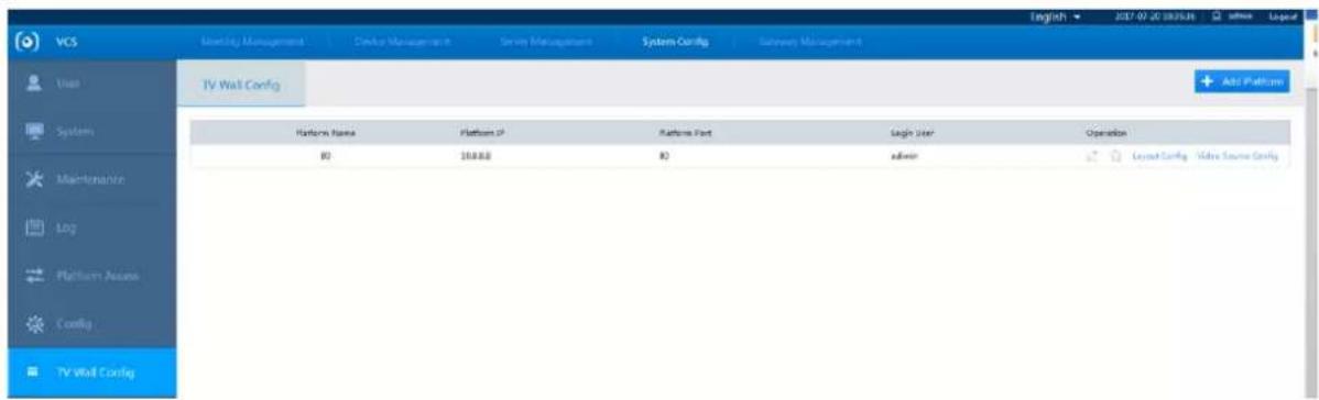
text_image
VCS Monitoring Management Module Management Server Management System Config Backway Management User TV Wall Config Add Platform Platform Name Platform IP Platform Port Xiaojin User Operation ID 200000 ID admin Layered Config Video Source Config Maintenance Log Platform Name Config TV Wall ConfigFigure 3-47
Step 2
+ Add Platform Click and the system will display the interface which is shown in Figure 3-48.

text_image
Add Platform Platform Name : Platform IP : . . . * Platform Port : Username : UserPassword : * OKFigure 3-48
Step 3
According to the actual situation, configure the name, IP, port, username and password of TV wall accessed platform, which is shown in Figure 3-49.
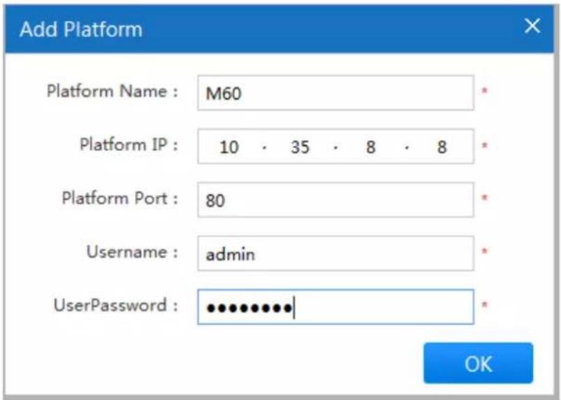
text_image
Add Platform Platform Name : M60 Platform IP : 10 · 35 · 8 · 8 Platform Port : 80 Username : admin UserPassword : ••••••••••| OKFigure 3-49
Step 4
Click "OK" to complete adding.
The system will display the interface which is shown in Figure 3-50.
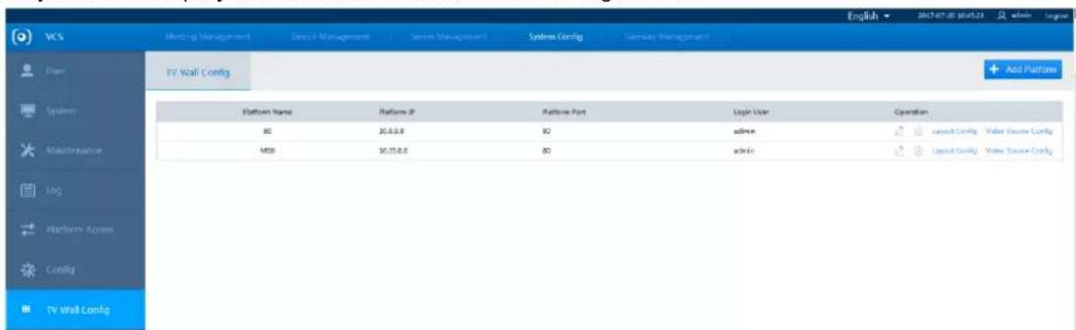
text_image
VCS Meeting Management Data/Management System Management Systems Config System Management English 2017-07-20 06:45:21 admin lograr TV Wall Config Add Platform Platform Name Platform IP Platform Port Login User Operation 80 30.0.0.0 80 admin MSI 30.15.0.0 80 admin layout Config Vide Source Config layout Config Vide Source ConfigFigure 3-50
Step 5
Click "Layout Config" to skip to the added video comprehensive platform to make config. Click "Video Source Config" to configure video source which can be output to TV wall.
3.8 Gateway Management
3.8.1 All Gateways
You can check all the gateways which are connected to the system.
Select "Gateway Management > All Gateway" and the system will display the interface which is shown in Figure 3-51.
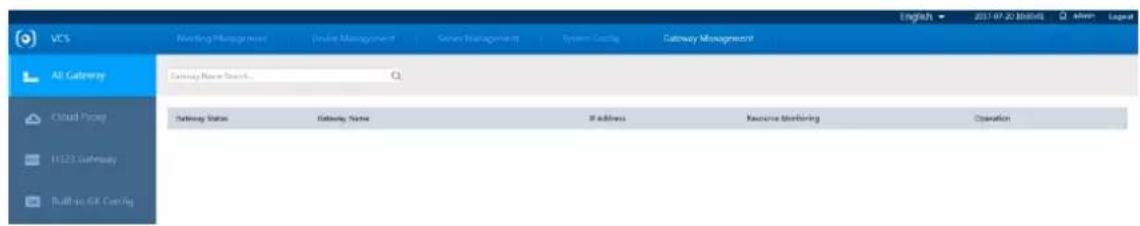
text_image
VCS All Gateway Email: Email Name Search... Gateway Status Gateway Name If Address Resource Monitoring OperationFigure 3-51
3.8.2 Cloud Proxy
Step 1
Select "Gateway Management > Cloud Proxy" and the system will display the interface of "Cloud Proxy", which is shown in Figure 3-52.

text_image
VCS All Gateway Cloud Proxy H123 Gateway Built-in DSL Carday Proxy IP SIP Port Media Server Port Proxy Name Operation OK English - 2017-07-01 19:54:28 admin - logit Add CloudFigure 3-52
Step 2
Click and the system will display the interface which is shown in Figure 3-53.
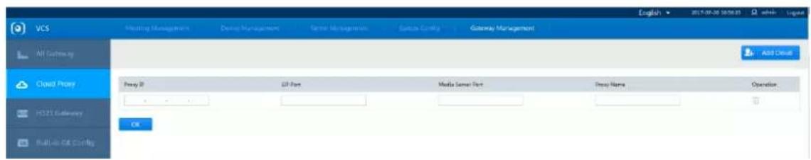
text_image
VCS Meeting Management Develop Management Service Management Security Control Gateway Management Add Default Cloud Proxy Proxy ID GUI Port Media Server Port Proxy Name Operation HCP35 Gateway Built-in GIS Config OKFigure 3-53
Step 3
Set "Proxy IP", "SIP Port", "Media Server Port" and "Proxy Name" according to the actual situation.
Step 4
OK Click to save settings.
3.8.3 H323 Gateway
3.8.3.1 H323 Config
Step 1
Select "Gateway Management > H323 Gateway > H323 Config" and the system will display the interface which is shown in Figure 3-54.

text_image
VCS All Gateway Closed Proxy H323 Gateway Built-in:GK Config H323 Config H323 Diagnosis GK Connection Mode: Disconnect GK GK Register SP: Internet SP mapping: Not enabled Internet SP: Registration Name: MCU Login, Password: Log level: General Call Bandwidth: Auto confirm according... Kbps Constraint I frame: 120 Communication port: 35000 - 35494 (TCP + UDP) FTP port: 35500 - 36999 (UDP) Vendor Adaptation: close Main Stream: H.264 HP H.264 BP Demo Stream: H.264 HP H.264 BP Audio: G.711e G712 G.722.1 Annex C/Polycom AAC LC 48K MPS Other: H.230 Kends MCU recording Gateway Version: L1.3641A Compile Time: 2017-07-05 14:38:18 Layer The server will reboost after successfully saved, please waitingFigure 3-54
Step 2
Configure H323 gateway according to actual needs.
Step 3
Click "Save" to save config.
3.8.3.2 H323 Diagnosis
H323 diagnosis can detect if there is any H323 device joins meeting.
Step 1
Select "Gateway Management > H323 Gateway > H323 Diagnosis" and the system will display the interface which is shown in Figure 3-55.

text_image
VCS H321 Config H321 Diagnick No H321 Donut join Meeting Add OptionsFigure 3-55
Step 2
Start Refresh Stop Refresh Click to begin to detect H323 device, click to stop detection.
3.8.3.3 Built-in GK Config
It can use specific number for interaction among video conferencing endpoints via configuring GK. Select "Gateway Management > Built-in GK Config" and the system will display the interface which is shown in Figure 3-56, please refer to Table 3-13 for more details about parameters.

text_image
VCS Mapping Management Device Management Server Management System Config Gateway Management AB Gateway Built-in Gk Config Enable Ethernet IP: Ethernet IP Config: 277 - 5 - 8 - 5 H430 Network Penetration: Save Built-in Gk Config English → 2017-07-20 11:30:01 LogistFigure 3-56
| Parameter | Note |
| Enable Extranet IP | It is to set if it enables extranet IP. |
| Extranet IP Config | It is to set extranet IP according to actual situation. |
| H.460 Network Penetration | It is to set all the endpoints have to be accessed to GK. |
Table 3-13
@jhua TECHNOLOGY
Dahua Technology Co., Ltd
Address: No.1199 Bin'an Road, Binjiang District, Hangzhou, PRC.
Postcode: 310053
Tel: +86-571-87688883
Fax: +86-571-87688815
Email:overseas@dahuatech.com
Website: www.dahuasecurity.com