
DC6151SSA - Range hood LG - Free user manual and instructions
Find the device manual for free DC6151SSA LG in PDF.

| Product Type | Range hood |
| Model Numbers | DC6151SSA, DC9151SSA |
| Installation Type | Ducted (external exhaust) or Recirculation |
| Minimum Distance from Cooktop | 650 mm |
| Exhaust Connection Diameter | 150 mm or 120 mm (with reducer flange) |
| Control Type | Touch panel with 4 speeds (including Intensive) |
| Lighting | 20 W halogen bulb (replaceable) |
| Grease Filters | Washable (aluminum or stainless steel) |
| Activated Charcoal Filter | Replaceable, not washable (4 months lifespan) |
| Filter Saturation Alarm | Grease: every 100 hours; Charcoal: every 200 hours |
| Electrical Class | Class I (requires earthing) |
| Power Supply | See rating plate (voltage and frequency) |
| Material | Stainless steel |
| Chimney Type | Telescopic (upper and lower sections) |
| Safety Features | Automatic intensive speed shut-off (10 min); child lock not specified |
| Included Accessories | Reducer flange, damper, chimney brackets, installation hardware, manual |
Frequently Asked Questions - DC6151SSA LG
User questions about DC6151SSA LG
0 question about this device. Answer the ones you know or ask your own.
Ask a new question about this device
Download the instructions for your Range hood in PDF format for free! Find your manual DC6151SSA - LG and take your electronic device back in hand. On this page are published all the documents necessary for the use of your device. DC6151SSA by LG.
USER MANUAL DC6151SSA LG
natural_image
Isometric line drawing of a vertical shelf or support structure with a base platform (no text or symbols)Model Numbers
DC6151SSA
DC9151SSA

Instruction Manual

Instructions Manual INDEX
RECOMMENDATIONS AND SUGGESTIONS....6
CHARACTERISTICS....7
INSTALLATION 8
USE....11
MAINTENANCE 12
INSTALLATION
The manufacturer will not be held liable for any damages resulting from incorrect or improper installation.
The minimum safety distance between the cooker top and the extractor hood is 650 mm.
Check that the mains voltage corresponds to that indicated on the rating plate fixed to the inside of the hood.
For Class I appliances, check that the domestic power supply guarantees adequate earthing.
Connect the extractor to the exhaust flue through a pipe of minimum diameter 120 mm. The route of the flue must be as short as possible.
Do not connect the extractor hood to exhaust ducts carrying combustion fumes (boilers, fireplaces, etc.).
If the extractor is used in conjunction with non-electrical appliances (e.g. gas burning appliances), a sufficient degree of aeration must be guaranteed in the room in order to prevent the backflow of exhaust gas. The kitchen must have an opening communicating directly with the open air in order to guarantee the entry of clean air.
⚠️ Installation of the extractor hood over a solid-fuel burner(coal, wood, etc.) which could constitute a potential fire hazard (e.g. due to flying sparks) is only permitted if the burner is equipped with an enclosed, non-removable cover and all country-specific regulations are observed. This restriction dose not apply to gas cookers and gas hobs.
⚠️ Regulations concerning the discharge of air have to be fulfilled.


natural_image
Illustration of a greenhouse with plants and smokestacks, crossed by a green ribbon (no text or symbols)USE
The extractor hood has been designed exclusively for household use to eliminate kitchen smells.
Never use the hood for purposes other than for which it has been designed.
⚠️ Never leave high naked flames under the hood when it is in operation.
Adjust the flame intensity to direct it onto the bottom of the pan only, making sure that it does not engulf the sides.
Deep fat fryers must be continuously monitored during use: overheated oil can burst into flames.
The hood should not be used by children or persons not instructed in its correct use.
Do not use the appliance if it is damaged in any way.
Never operate the extractor hood without a grease filter.
Do not flambe food directly under the extractor hood.
MAINTENANCE
Switch off or unplug the appliance from the mains supply before carrying out any maintenance work.
Clean and/or replace the Filters after the specified time period.
Clean the hood using a damp cloth and a neutral liquid detergent.
Defective bulbs should be replaced immediately to prevent the remaining bulbs from overloading.
There is a fire risk if cleaning is not carried out in accordance with the instructions.
Dimensions

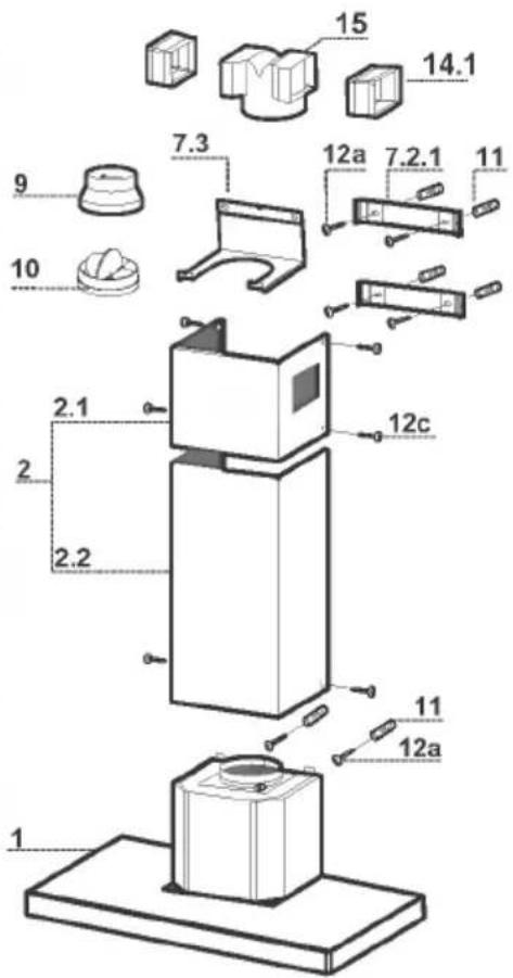
Components
| Ref. | Q.ty | Product Components |
| 1 | 1 | Hood Body, complete with: Controls, Light, Blower, Filters |
| 2 | 1 | Telescopic Chimney comprising: |
| 2.1 | 1 | Upper Section |
| 2.2 | 1 | Lower Section |
| 9 | 1 | Reducer Flange ø 150-120 mm |
| 10 | 1 | Damper ø 150 |
| 14.1 | 2 | Air Outlet Connection Extension |
| 15 | 1 | Air Outlet Connection |
| Ref. | Q.ty | Installation Components |
| 7.2.1 | 2 | Upper Chimney Section Fixing Brackets |
| 7.3 | 1 | Air Outlet Connection Support |
| 11 | 6 | Wall Plugs |
| 12a | 6 | Screws 4,2 x 44,4 |
| 12c | 6 | Screws 2,9 x 9,5 |
| Q.ty | Documentation | |
| 1 | Instruction Manual |
Wall drilling and bracket fixing

Wall marking:
- Draw a vertical line on the supporting wall up to the ceiling, or as high as practical, at the centre of the area in which the hood will be installed.
- Draw a horizontal line at 650 mm above the hob.
- Place bracket 7.2.1 on the wall as shown about 1-2 mm from the ceiling or upper limit aligning the centre (notch) with the vertical reference line.
- Mark the wall at the centres of the holes in the bracket.
- Place bracket 7.2.1 on the wall as shown at X mm below the first bracket (X = height of the upper chimney section supplied), aligning the centre (notch) with the vertical line.
• Mark the wall at the centres of the holes in the bracket. - Mark a reference point as indicated at 116 mm from the vertical reference line and 320 mm above the horizontal reference line.
- Repeat this operation on the other side.
- Drill 8 mm holes at all the centre points marked.
- Insert the wall plugs 11 in the holes.
• Fix the lower bracket 7.2.1 using the 12a screws (4,2 x 44,4) supplied. - Fix the upper bracket 7.2.1 and the air outlet connection support 7.3 together using the 2 screws 12a (4,2 x 44,4) supplied.
- Insert the two screws 12a (4,2 x 44,4) supplied in the hood body fixing holes, leaving a gap of 5-6 mm between the wall and the head of the screw.
Mounting the hood body
- Before attaching the hood body, tighten the two screws Vr located on the hood body mounting points.
- Hook the hood body onto the screws 12a.
• Fully tighten support screws 12a. - Adjust screws Vr to level the hood body.
Connections
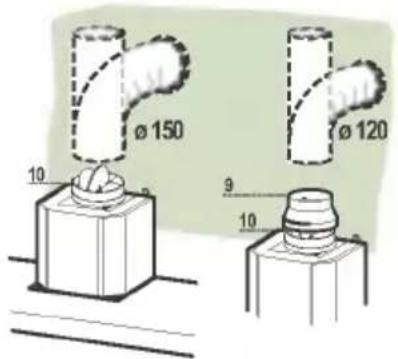
DUCTED VERSION AIR EXHAUST SYSTEM
When installing the ducted version, connect the hood to the chimney using either a flexible or rigid pipe 150 or 120mm, the choice of which is left to the installer.
To install a 150
• To install the dumper 10
- Fix the pipe in position using sufficient pipe clamps (not supplied).
To install a 120
- To install a 120 mm air exhaust connection, insert the reducer flange 9 on the dumper 10.
- Fix the pipe in position using sufficient pipe clamps (not supplied).
- Remove any activated charcoal filters.
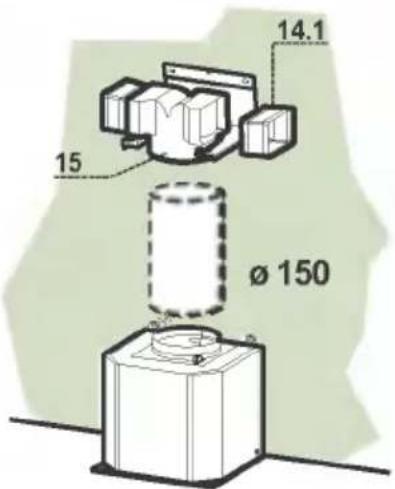
RECIRCULATION VERSION AIR OUTLET
- Put connection 15 into the connection support 7.3.
- Insert the connection extension pieces laterally 14.1 in connection 15.
- Make sure that the outlet of the extension pieces 14.1 is horizontally and vertically aligned with the chimney outlets.
- Connect the air outlet connection 15 to the hood body outlet using either a flexible or rigid pipe 150 mm, the choice of which is left to the installer.
- Ensure that the activated charcoal filters have been inserted.

ELECTRICAL CONNECTION
- Connect the hood to the mains through a two-pole switch having a contact gap of at least 3 mm.
- Remove the grease filters (see paragraph Maintenance) being sure that the connector of the feeding cable is correctly inserted in the socket placed on the side of the fan.

natural_image
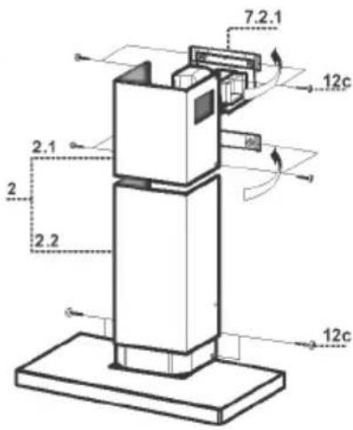
Diagram showing a mechanical component with an inset view of a pipe fitting and a green arrow indicating direction (no text or symbols present)Flue assembly
Upper exhaust flue
- Slightly widen the two sides of the upper flue and hook them behind the brackets 7.2.1, making sure that they are well seated.
- Secure the sides to the brackets using the 4 screws 12c (2,9 x 9,5) supplied.
- Make sure that the outlet of the extensions pieces is aligned with the chimney outlets.
Lower exhaust flue
- Slightly widen the two sides of the flue and hook them between the upper flue and the wall, making sure that they are well seated.
- Fix the lower part laterally to the hood body using the 2 screws 12c (2,9 x 9,5) supplied.
flowchart
graph LR
    A["Sun"] --> B["L"]
    B --> C["T1"]
    C --> D["T2"]
    D --> E["T3"]
    E --> F["T4"]
    F --> G["F"]
    H["S1"] -.-> G
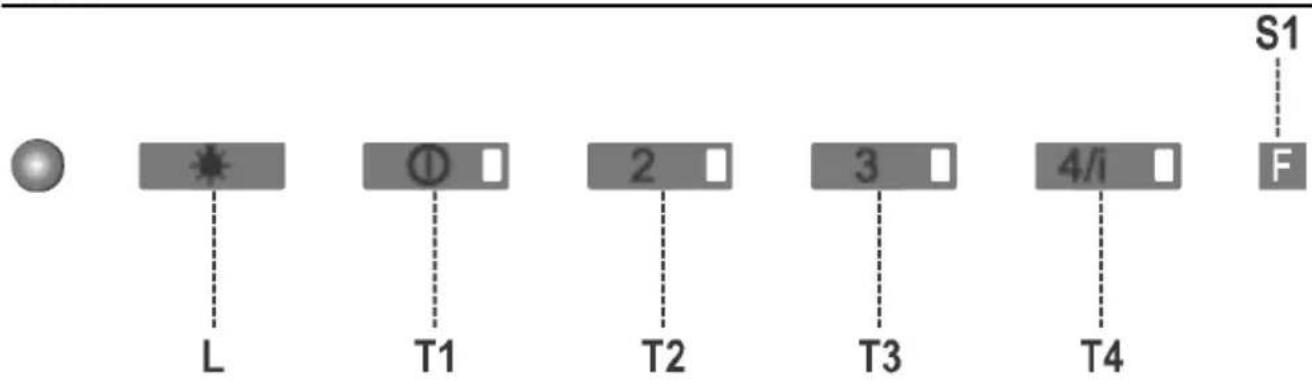
Control Panel
The hood can be switched on pushing directly onto the requested speed without firstly having to select 0/1 button.
| KEY | LED | FUNCTIONS | |
| L | 0/1 Light | Turns lighting on and off. | |
| T1 | 0/1 Motor on | First speed.When pressed for about 1 seconds the motor is switched off. | |
| T2 | Speed | on | Second speed. |
| T3 | Speed | on | Third speed. |
| T4 | Speed | Fixed | Max. speed |
| Flashing | Intensive speed.Suitable for the strongest cooking vapours and odours.The function becomes active when the button is pushed for about 2 seconds. After 10 minutes of functioning it turns off automatically. This function can be interrupted by means of pressing any of the buttons. | ||
| S1 | Led | Fixed | Indicates that the Metal grease filters saturation alarm has been triggered, and the filters need to be washed. The alarm is triggered after 100 working hours. (Reset; check the Maintenance-paragraph) |
| Flashing | indicates that the activated charcoal odour filter saturation alarm has been triggered, and the filter has to be replaced; the metal grease filters must also be washed. The activated charcoal odour filter is triggered after 200 working hours. (Activation and Reset; check the Maintenance-paragraph)) | ||
Grease filters
CLEANING METAL GREASE FILTERS
Alarm signal reset
- Switch off the lights and extractor motor.
- Press button T3 for at least 3 seconds, until the leds T1,T4 start to flash.
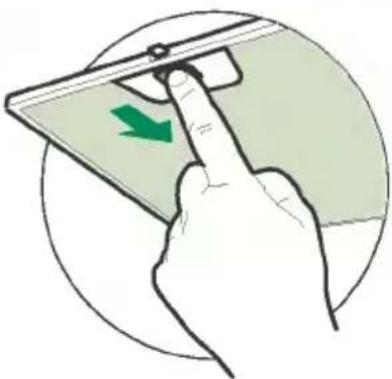
Cleaning the filters (Aluminum filters)
- The filters are washable and must be cleaned when the LED S1 lights up or at least every 2 months of operation, or more frequently for particularly heavy usage.
- Remove the filters one at a time by pushing them towards the back of the group and pulling down at the same time.
- Wash the filters, taking care not to bend them. Allow them to dry before refitting.
- When refitting the filters, make sure that the handle is visible on the outside.
natural_image
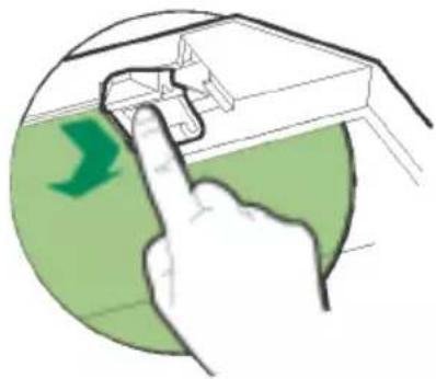
Illustration of a hand pressing a device with a green arrow indicating left motion (no text or symbols)Cleaning the filters (Stainless Steel filters)
- The filters are washable and must be cleaned when the LED S1 lights up or at least every 2 months of operation, or more frequently for particularly heavy usage.
- Remove the filters one at a time, supporting them with one hand and turning the safety knobs (pull and turn).
- Wash the filters, taking care not to bend them. Allow them to dry before refitting.
- Replace them and fix them using the safety knobs provided (pull and turn).

natural_image
Illustration of hands performing a task with a green arrow indicating rotation (no text or symbols present)- The filter is not washable and cannot be regenerated. It must be replaced when led S1 flashes or at least every 4 months. The alarm signal will only light up when the extractor motor is switched on.
Alarm signal activation
- In Recirculation version Hoods, the Filter saturation alarm can be enabled on installation or at a later date. Turn the Lights and the suction Motor off.
- Disconnect the Hood using the Main switch or the double-pole switch on the mains power supply.
- Restore the connection by pressing and holding T1.
- Release the button. All five LEDs are turned on
- Within 3 seconds press T1 until LEDs T1 and T4 flash in confirmation: LED flashes twice - Activated charcoal filter saturation alarm ENABLED LED flashes once - Activated charcoal filter saturation alarm DISABLED
Replacing the activated charcoal filter
Alarm signal reset
- Switch off the lights and extractor motor.
- Press button T3 for at least 3 seconds, until the leds start to flash.
Replacing the Filter
- Remove the metal grease filters
- Remove the saturated activated carbon filter by releasing the fixing hooks
• Fit the new filter by hooking it into its seating - Replace the metal grease filters.
natural_image
Illustration of a hand interacting with a device, showing a green arrow pointing to the screen (no text or symbols present)Lighting
LIGHT REPLACEMENT
20 W halogen light.
- Remove the snap-on lamp cover by levering it from under the metal ring, supporting it with one hand.
- Remove the halogen lamp from the lamp holder by pulling gently.
- Replace the lamp with a new one of the same type, making sure that you insert the two pins properly into the housings on the lamp holder.
- Replace the snap-on lamp cover.
When switched on, the halogen bulbs become very hot. Even for some time after the bulbs have been switched off there is still a risk of burns.

natural_image
Illustration of a hand holding a small object above a circular frame (no text or symbols)
Disposal of your old appliance
- When this crossed-out wheeled bin symbol is attached to a product it means the product is covered by the European Directive 2002/96/EC.
- All electrical and electronic products should be disposed of separately from the municipal waste stream via designated collection facilities appointed by the government or the local authorities.
- The correct disposal of your old appliance will help prevent potential negative consequences for the environment and human health.
- For more detailed information about disposal of your old appliance, please contact your city office, waste disposal service or the shop where you purchased the product.


- Instructions Manual INDEX
- INSTALLATION
- USE
- MAINTENANCE
- Wall drilling and bracket fixing
- Wall marking:
- Mounting the hood body
- Connections
- DUCTED VERSION AIR EXHAUST SYSTEM
- To install a 150
- To install a 120
- RECIRCULATION VERSION AIR OUTLET
- ELECTRICAL CONNECTION
- Flue assembly
- Upper exhaust flue
- Lower exhaust flue
- Control Panel
- Grease filters
- CLEANING METAL GREASE FILTERS
- Alarm signal reset
- Cleaning the filters (Aluminum filters)
- Cleaning the filters (Stainless Steel filters)
- Alarm signal activation
- Replacing the activated charcoal filter
- Replacing the Filter
- Lighting
- LIGHT REPLACEMENT
- Disposal of your old appliance
Brand : LG
Model : DC6151SSA
Category : Range hood