WGCXT1TVEG - Switch HAGER - Free user manual and instructions
Find the device manual for free WGCXT1TVEG HAGER in PDF.

User questions about WGCXT1TVEG HAGER
0 question about this device. Answer the ones you know or ask your own.
Ask a new question about this device
Download the instructions for your Switch in PDF format for free! Find your manual WGCXT1TVEG - HAGER and take your electronic device back in hand. On this page are published all the documents necessary for the use of your device. WGCXT1TVEG by HAGER.
USER MANUAL WGCXT1TVEG HAGER
Electrical equipment must only be installed and assembled by a qualified electrician in accordance with the relevant installation standards, regulations, directives and safety and accident prevention directives of the country.
Failure to comply with these installation instructions may result in damage to the device, fire or other hazards.
Function
The TV outlets are used for supplying digital or analogue TV signals.
| Version Connector Area of application | |
| TV outlet IEC-jack For use as single socket |
Correct use
- For the flush-mounted installation in standard wall boxes (wall box depth ≥ 47 mm).
- Only suitable for use in indoor areas with no drip and no spray water.
Technical data
Frequency range: 5 ... 1000 MHz
Information for electricians Installation and electrical connection
Preparing the device for installation

text_image
1A Hager Muse Frame Notches
text_image
Hager Inspire1B Frame Cover plate Notches- Carefully loosen the frame on the notches with a flat-blade screwdriver. Lift up and remove the frame (1A/1B).
■ Hager Inspire: Remove the cover plate also with a flat-blade screwdriver (1B).
Connecting the TV outlet
■ Shorten and route coaxial transmission line in the wall box. When doing so, do not bend coaxial transmission line too far.
text_image
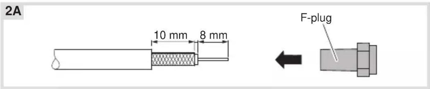
2A 10 mm 8 mm F-plug- Strip coaxial transmission line and attach supplied F-plug (2A).
text_image
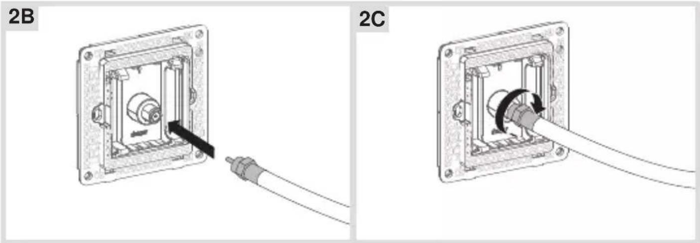
2B 2C■ Connect and screw the assembled line to the F-jack on the rear of the TV outlet (2B/2C).
Installing the device into the wall box

natural_image
Mechanical assembly diagram showing a component being inserted into a housing, with no visible text or symbols.■ After wiring, fix the device with the two screws attached into the wall box (3).
Assembling the covers

text_image
4A Hager Muse Frame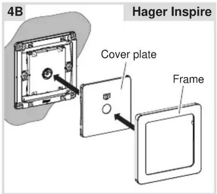
text_image
4B Hager Inspire Cover plate Frame■ Hager Muse: Snap the frame onto the device (4A).
■ Hager Inspire: Place the cover plate in the correct position and fix with frame (4B).
2-5gang frames are available for multiple combinations.