SAMVVH4 - Power strip Suttle - Free user manual and instructions
Find the device manual for free SAMVVH4 Suttle in PDF.

User questions about SAMVVH4 Suttle
0 question about this device. Answer the ones you know or ask your own.
Ask a new question about this device
Download the instructions for your Power strip in PDF format for free! Find your manual SAMVVH4 - Suttle and take your electronic device back in hand. On this page are published all the documents necessary for the use of your device. SAMVVH4 by Suttle.
USER MANUAL SAMVVH4 Suttle
Align the mounting pins with the grid holes on the back of the enclosure. With the mounting pin plungers in the "out" position, press the unit into the grid in the desired location, secure by pushing the plungers in.
Terminate incoming service line:
Run twisted pair cable to the 110 IDC connector marked "LINE IN" from the telephone company demarcation point. Terminate individual wires following the 110 IDC Termination Procedure described below.

text_image
Procedure described below. Premise IDC marked 1-10 SECURITY RJ3IX Voice and Video Combo Module LINE IN OUT "LINE IN" Suttle Line 4 Line 3 Line 2 Line 1 Alarm Interface Test110 IDC Termination Procedure
Strip 3 in. of outer jacket from the cable. Terminate the individual cable pairs on the 110 IDC. Starting at the blue position on the IDC, begin with the white wire of each pair as you progress to the orange position on the IDC as shown below. Press wires into slots with a 110-punch tool. Trim and discard excess wires.
NOTE: one pair of wires corresponds to each line from the phone company. (Line 1 = blue, Line 2 = orange, Line 3 = green, Line 4 = brown)
Brown White/Brown Green White/Green Orange White/Orange Blue White/Blue

natural_image
Diagram of a mechanical or electrical component with multiple curved chains and a central shaft (no text or symbols)Terminate premise wiring:
Run twisted pair cable from the 110 IDC connectors numbered 1 through 10 to the telephone outlets throughout the premise. Terminate individual wires following the 110 IDC Termination Procedure described above. The wire pair locations can be recorded on the wiring label supplied with this module.
Attach the wiring label to the inside of the enclosure cover.
The cables should be bundled and secured to the SAM-VV module. Loop a zip tie or other strap through the holes located on the left or right side of the module to secure the cables.
text_image
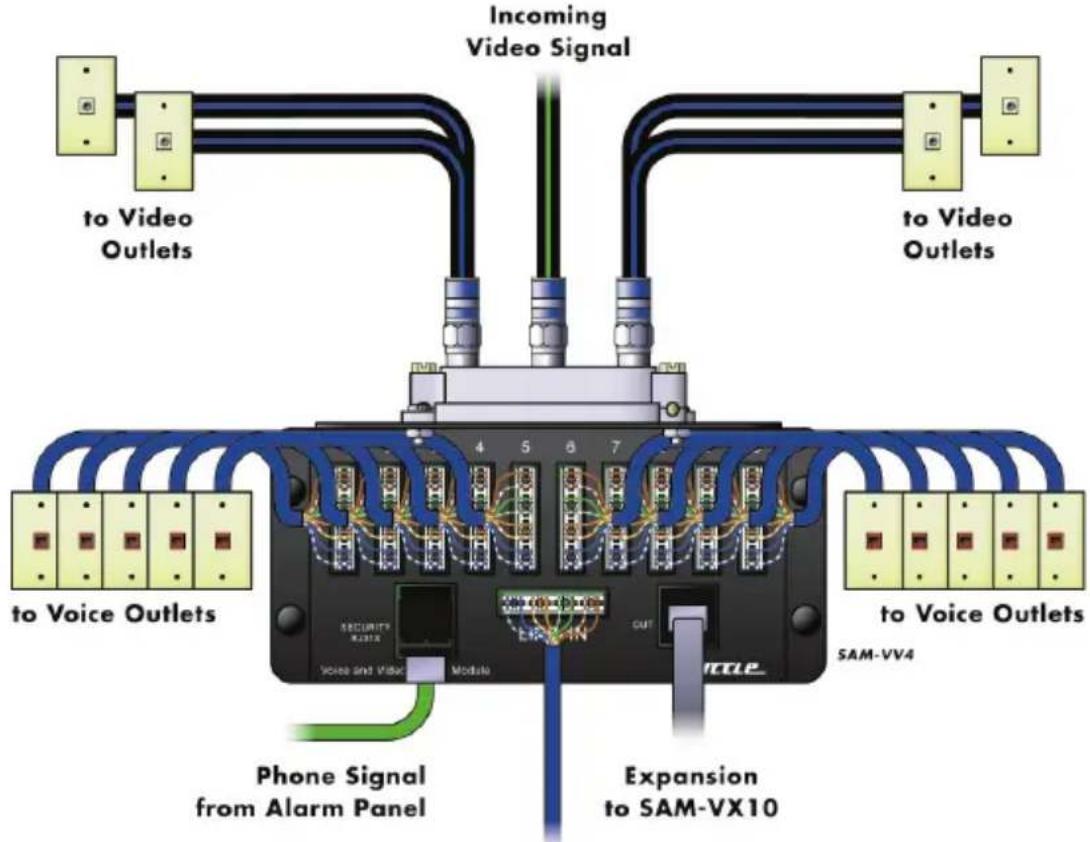
Incoming Video Signal to Video Outlets to Voice Outlets 4 5 6 7 SECURITY X231X Voice and Video Module EX-EN OUT SM-VV4 Phone Signal from Alarm Panel Expansion to SAM-VX101-4 Lines In
Testing incoming service line:
To test the incoming service lines, plug a tester into the RJ45 port marked "OUT". This port is an 8-conductor jack wired to T568A. Line 1 is on conductors 5 & 4, Line 2 is on conductors 3 & 6, Line 3 is on conductors 1 & 2 and Line 4 is on conductors 7 & 8. This RJ45 port may also be used to jumper to a SAM-VX10 module if additional premise distribution is required. Use an 8-conductor line cord wired 1:1.
Alarm Interface connection:
The 10-port Voice module features a security interface. In an emergency situation, the security system can over-ride telephone service on LINE 1 when the alarm is activated. Connect an 8-conductor line cord from the alarm dialer to the port marked "Security RJ31X" on the 10-port Voice module. The circuit for Line 1 (blue pair) passes through this RJ31X port, from the 110 IDC connector marked "LINE IN" to the 110 IDC connectors numbered 1 through 10. ____ "in" fitting
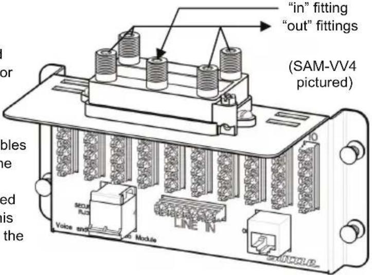
Video service:
Run the incoming F-connectorized video coaxial cable to the connector fitting on the splitter labeled "in". Run F-connectorized coaxial drop cables to the outlets throughout the premise. Connect the drop cables to the "out" connector fittings on the splitter.
The cable locations can be recorded on the wiring label supplied with this module. Attach the wiring label to the inside of the enclosure cover.
text_image
"in" fitting "out" fittings (SAM-VV4 pictured) MOUNT RIO LINE N Voice and ModuleImportant Information:
- Read and understand all instructions. Follow all instructions and warnings marked on the product.
- Do not use this product near water, --e.g., near a bath tub, wash basin, kitchen sink, wet basement, or near a swimming pool.
- Never push objects of any kind into this product through openings, as they may contact dangerous voltages.
- SAVE THESE INSTRUCTIONS.
Safety Information:
- Never install communications wiring during a lightning storm.
- Never touch uninsulated wires or terminals unless the wiring has been disconnected at the network interface.
- Never install communications components in wet locations unless the components are designed specifically for use in wet locations.