VSC8224 - Electronic component Microchip - Free user manual and instructions
Find the device manual for free VSC8224 Microchip in PDF.

User questions about VSC8224 Microchip
0 question about this device. Answer the ones you know or ask your own.
Ask a new question about this device
Download the instructions for your Electronic component in PDF format for free! Find your manual VSC8224 - Microchip and take your electronic device back in hand. On this page are published all the documents necessary for the use of your device. VSC8224 by Microchip.
USER MANUAL VSC8224 Microchip
2.2.1 Vitesse Documents 2
2.2.2 IEEE Standards 2
2.2.3 Terms and Abbreviations 2
3 Factors in Choosing a Gigabit PHY 4
3.1 What Interface Does the MAC/Switch Require? 4
3.2 What Media Interface Must Be Supported? 4
3.2.1 10/100/1000BASE-T Copper Media 4
3.2.2 1000BASE-X Fiber Media 4
3.2.3 100BASE-FX Fiber Media 5
3.2.4 10/100/1000BASE-T Copper SFP Media 5
3.2.5 Dual Media 5
4 Selecting the Appropriate SimpliPHY Device 6
5 Fiber/Dual Media Design Guidelines 7
5.1 Connecting to 1000BASE-X Fiber Optic Transceiver 7
5.2 Connecting to 1000BASE-X Fiber GBICs 8
5.3 Connecting to 1000BASE-X Fiber or 1000BASE-T Copper SFPs 8
5.4 Connecting to 100BASE-FX Fiber SFPs 9
6 Connecting to Dual Media Designs 11
6.1 VSC8211 Dual Media 11
6.2 VSC8224 Dual Media 12
6.3 VSC8234 Dual Media 12
6.4 VSC8558 Dual Media 13
6.5 VSC8658 Dual Media 13
6.6 VSC8664 Dual Media 14
1 Revision History
The revision history describes the changes that were implemented in the document. The changes are listed by revision, starting with the most current publication.
1.1 Revision 2.02
Revision 2.02 was released in October 2007. Added VSC8634 and VSC8664.
1.2 Revision 2.01
Revision 2.01 was released in November 2006. Added VSC8658. Added GMII support in Table 3.
1.3 Revision 2.00
Revision 2.00 was released in July 2006. Updated document format. Added VSC8601 and VSC8641.
1.4 Revision 1.02
Revision 1.02 was released in November 2005. Added 100BASE-FX information.
1.5 Revision 1.01
Revision 1.01 was released in June 2005. Updated document format. Added VSC8538 and VSC8558.
1.6 Revision 1.00
Revision 1.00 was the first release of this document. It was published in October 2005.
2 Introduction
The growth of Gigabit Ethernet has created a demand for gigabit PHYs capable of connecting to an existing copper-cable system or to a fiber-optic network. Given the increasing number of PHY products with unique MAC and media interfaces, it can be a challenge to determine which PHY device is appropriate for a given system. This application note will assist a system or high-speed board designer in determining which SimpliPHY device to implement into their design. This document will address copper media, fiber media, and dual media (selectable copper or fiber media) capable PHYs.
2.1 Audience
The target audiences for this document are system or high-speed board designers determining which SimpliPHY device to implement into their design.
2.2 References
2.2.1 Vitesse Documents
• VSC8201 Datasheet
• VSC8211 Datasheet
• VSC8221 Datasheet
• VSC8224 Datasheet
• VSC8234 Datasheet
• VSC8244 Datasheet
• VSC8538 Datasheet
• VSC8558 Datasheet
• VSC8601 Datasheet
• VSC8641 Datasheet
VSC8658 Datasheet
• VSC8634 Datasheet
• VSC8664 Datasheet
2.2.2 IEEE Standards
- IEEE802.3 - CSMA/CD Access Method and Physical Layer Specification
2.2.3 Terms and Abbreviations
Table 1 • Terms and Abbreviations
| Term Explanation |
| AC Alternative Current |
| ASIC Application-Specific Integrated Circuit |
| DDR Double-Data Rate |
| GBIC GigaBit Interface Converter |
| GPIO General Purpose Input-Output |
| LED Light Emitting Diode |
| LOS Loss Of Signal |
| MAC Media Access Control |
| MII Media Independent Interface |
| MDI Media Dependent Interface |
| PHY PHYSical layer device |
| RGMII Reduced Gigabit Media Independent Interface |
Term Explanation
SFP Small Form-factor Pluggable
SGMII Serial Gigabit Media Independent Interface
SIGDET SIGnal DETect
3 Factors in Choosing a Gigabit PHY
There are two main factors that will guide a designer in choosing which SimpliPHY device is appropriate for their design:
• What interface does the MAC/Switch require?
• What media interface(s) must be supported?
3.1 What Interface Does the MAC/Switch Require?
One factor in selecting a PHY device for a given Gigabit Ethernet design will depend on what interface the chosen MAC or Switch requires. The first Gigabit Ethernet devices used GMII (Gigabit Media Independent Interface) for data transfer between the MAC and PHY. GMII is a variant of MII (Media Independent Interface) that was used for 10/100BASE-T systems. However, GMII has roughly twice the number of pins as MII. As Gigabit Ethernet designs have increased in the port count, the pin count per port limits the feasible size of a product solution. To lower pin count, designs are now employing the following two Gigabit-capable reduced pin interfaces:
- RGMII (Reduced Gigabit Media Independent Interface) effectively reduces the GMII pin count by half by using the clock and data pins in a DDR (double-data rate) clocking fashion.
- SGMII (Serial Gigabit Media Independent Interface) serializes a gigabit interface (such as GMII) into a high-speed, two-pin differential interface. Using SGMII can reduce the pin count to four pins per Ethernet port.
The choice of MAC/switch device will largely affect which interface the PHY is required to provide.
3.2 What Media Interface Must Be Supported?
Vitesse SimpliPHY devices support several media interfaces:
• 10/100/1000BASE-T copper
• 1000BASE-X fiber
• 100BASE-FX fiber
• 10/100/1000BASE-T copper SFPs
- Dual media (capable of actively selecting between copper media or 1000BASEX/100BASE-FX fiber as well as copper SFP interfaces)
3.2.1 10/100/1000BASE-T Copper Media
The SimpliPHY devices have copper media interfaces that support 10/100/1000BASE-T Ethernet as defined by the IEEE 802.3-2000 standard. They also support IEEE 802.3 Clause 28 auto-negotiation for full backward compatibility with new and older generation copper network systems. If the link partner does not support autonegotiation, the SimpliPHY device will automatically use a parallel-detection method to select the appropriate link speed (for 10/100BASE-T speed only. 1000BASE-T requires autonegotiation as outlined by the IEEE 802.3 standard).
3.2.2 1000BASE-X Fiber Media
A fiber-optic transceiver converts electrical signals into optical signals, and vice versa. Gigabit Ethernet over fiber (1000BASE-X) is defined by the IEEE 802.3-2002 standard. Clause 36 of the standard defines fiber auto-negotiation. Fiber-optic transceivers are provisioned into systems for cases where optical cabling is appropriate for cases of long-haul transmission or for interfacing with existing fiber networks. For added flexibility, the industry has provided guidelines for flexible module interfaces. Modules such as Gigabit Interface Converter (GBIC) can be plugged into an Ethernet-based system that contains GBIC receptacles. Other modules, such as Small Form-Factor Pluggable (SFPs) defined by the SFP Multi-Source Agreement also allow for a wide range of fiber and copper media interface solutions. Approximately half the size of GBIC, SFPs are small enough to allow for multiple ports on a system to be flexible and upgradeable to meet the needs of any specific customer network application.
3.2.3 100BASE-FX Fiber Media
Fast Ethernet over fiber (100BASE-FX) is defined by the IEEE 802.3-2002 standard in Clause 26. These SFPs are similar to 1000BASE-X fiber SFPs, except they support 100 Mbps instead of 1000 Mbps.
3.2.4 10/100/1000BASE-T Copper SFP Media
Copper SFPs are similar to fiber SFPs except that they support the IEEE802.3 copper media. Copper SFPs are available in 1000BASE-T only, or they can also offer full 10/100/1000BASE-T speeds if these SFPs support SGMII connections to the host system.
3.2.5 Dual Media
An Ethernet PHY can also allow for selectable copper or fiber media. This provides the utmost level of configurability, since any of the above interfaces could interface to a single PHY on an Ethernet port.
4 Selecting the Appropriate SimpliPHY Device
The following table is provided as a guide in deciding which SimpliPHY product is appropriate for a given design.
Table 2 • SimpliPHY Selection Matrix
| Single Media Applications Dual Media Applications | ||||||
| 10/100/1000BASE-T Copper | 1000BASE-X Fiber ^1 | 100BASE-FX Fiber ^1 | 10/100/1000BASE-T CopperSFP | 10/100/1000BASE-T Copperand1000BASE-X Fiber | 10/100/1000BASE-T Copperand100BASE-FXFiber | 10/10/1000BASE-T Copper and 10/100/1000BASE-T Copper SFP |
| GMII VSC8201VSC8641 | VSC8211 | VSC8211 | VSC8211 VSC8211 | |||
| RGMII VSC8201VSC8211VSC8224VSC8244VSC8601VSC8641 | VSC8211VSC8224 | VSC8211 | VSC8211 | |||
| VSC8224 | ||||||
| SGMII VSC8211 | VSC8558 | VSC8211^3 | VSC8211 | VSC8234^2 | VSC8658 | VSC8211 |
| 1. Includes fiber optic transceiver, GBIC and SFR interface designs | ||||||
| VSC8221 | VSC8598 | VSC8221 | VSC8598 | VSC8598 | VSC8664 | VSC82342 |
| 2. Requires additional device | ||||||
| VSC82341 | VSC8664 | VSC8538^3 | VSC8658 | VSC8658 | VSC8558 | |
| 3. Provided on the Copper Media MDI Pins. For details for each PHY, refer to Its Supporting 100BASE-FX Fiber Media application note. | ||||||
| VSC8538 | VSC8538 | VSC8664 | VSC8664 | VSC8698 | ||
| VSC8558 | VSC8664 | |||||
| Example on vscaw to use this table: VSC8664 | ||||||
| VSC8658 | ||||||
- If the application requires a single port containing RGMII and Copper media, then the user should choose the VSC8601.
- If the application requires a single RGMII to 1000BASE-X conversion, the user should choose the VSC8211.
- If the application is a multi-port and requires an SGMII MAC interface and both copper and 1000BASE-X fiber media, then the user should choose the VSC8558.
- If the application requires a multi-port SGMII MAC interface and be able to support all possible copper and fiber media interfaces, then the user should choose the VSC8658 or VSC8664.
5 Fiber/Dual Media Design Guidelines
This section will provide guidelines to designers who plan to implement SimpliPHY devices for fiber or dual media applications.
5.1 Connecting to 1000BASE-X Fiber Optic Transceiver
To connect a SimpliPHY device to a fiber-optic transceiver, please use the following guidelines and reference schematic.
Note: If using a VSC8211 in SGMII-Fiber (or SerDes) media mode, RD output pins and TD input pins in the text will refer to SDO output pins and SDI input pins of the VSC8211. If using a VSC8558, RD output pins and TD input pins in the text will refer to SER_DOP output pins and SER_DIP input pins of the VSC8558.
Note: The Agilent HFBR-53A-5VEM/FM fiber-optic transceiver was used as a guide for connecting fiber-optic transceivers to SimpliPHY devices.
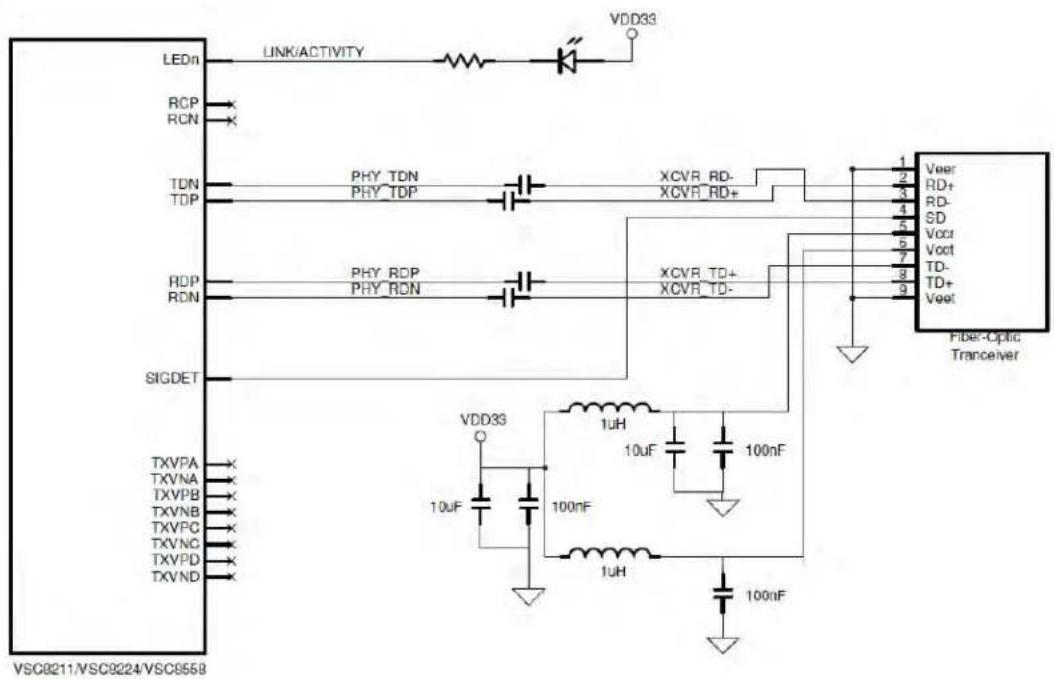
- Connect the PHY's RD output pins to the TD input pins of the fiber-optic transceiver.
- Connect the PHY's TD input pins to the RD output pins of the fiber-optic transceiver.
- The RD and TD traces must be targeted to be 50-ohm impedance traces and be routed as differential pairs.
- Connect the PHY's SIGDET input pin to the SD output pin of the fiber-optic transceiver.
- Leave the PHY's RC output clock pins as 'no-connect'.
- Leave the copper media interface as 'no-connect'.
- Use one of the PHY's LED pins, select LINK/ACTIVITY, and connect it to the CATHODE pin of an LED. This can be used to indicate when the fiber is linked and has data activity present.
- Depending on certain fiber optic transceivers, the 0.1uF AC coupling capacitors may not be needed. For example, the HFBR-53A-5VEM transceiver has internal AC-coupling capacitors.
Figure 1 • SimpliPHY to Fiber Optic Transceiver Reference Schematic
text_image
LEDn LINK/ACTIVITY RCP RCN TDN TDP PHY_TDN PHY_TDP XCVR_RD- XCVR_RD+ 1 2 3 4 5 6 7 8 9 VeeR RD+ RD- SD Vccr Vccf TD- TD+ Veet SIGDET TXVPA TXVNA TXVPB TXVNB TXVFC TXVNC TXVPD TXVND VDD33 1uH 10uF 100nF 1uH 100nF Fiber-Optic Trancever VSC9211/VSC9224/VSC95585.2 Connecting to 1000BASE-X Fiber GBICs
To connect a SimpliPHY device to a fiber-GBIC device, please use the following guidelines and reference schematic.
Note: If using a VSC8211 in SGMII-Fiber (or SerDes) media mode, RD output pins and TD input pins in the text will refer to SDO output pins and SDI input pins of the VSC8211. If using a VSC8558, RD output pins and TD input pins in the text will refer to SER_DOP output pins and SER_DIP input pins of the VSC8558.
- Connect the PHY's RD output pins to the TD input pins of the fiber GBIC connector.
- Connect the PHY's TD input pins to the RD output pins of the fiber GBIC connector.
- The RD and TD traces must be targeted to be 75-ohm impedance traces and be routed as a differential pairs. Set the PHY's MII Register 17E.1 = 1 for 75-ohm mode.
- Connect the PHY's SIGDET input pin to the LOS output pin of the fiber GBIC connector. Set MII Register 19E.0 = 1 to set the SIGDET pin to 'active-low'. This will set the pin to properly receive the LOS behavior without additional glue logic.
- The GBIC's Present, SCL, SDA, TX_DIS, and TX_FAULT signals may be connected to the Switch/MAC/ASIC. If using multiple GBICs, it may be best to implement an I2C controller as all GBIC devices have an I2C address = 00000.
- Leave the PHY's RC output clock pins as 'no-connect'.
- Leave the copper media interface as 'no-connect'.
- Use one of the PHY's LED pins, select LINK/ACTIVITY, and connect it to the CATHODE pin of an LED. This can be used to indicate when the GBIC is linked and has data activity present.
• Depending on certain fiber GBICs, the 0.1uF AC coupling capacitors may not be needed. - All pull-up resistors should have a value between 4.7K to 10K ohms.
Figure 2 • SimpliPHY to Fiber GBIC Reference Schematic

text_image
LEDn LINK/ACTNITY VDD35 RCP RCN TDN TDP PHY_TDM PHY_TDP GBIC_RX- GBIC_RX+ RDPP RDN PHY_RDP PHY_RDN GBIC_TX+ GBIC_TX- SIGOET TXVPA TXVNA TXVPB TXVNS TXVPC TXVND TXVPD TXVND VDD33 1uF 10uF 100uF 1uH 100uF 1uF GBIC Connector RGND RX_LOS 1 RX RGND 2 RX+ RGND 3 RGND MOU_DEF 4 VCCR MOU_DEF1 5 VCCT MOU_DEF2 6 VGND TX_DISABLE 7 TX- TGND 8 TGND TX_FAULT 9 TBND TX_FAULT 10 GBIC Present GBIC_SCL GBIC_SDA GBIC_TXDIS GBIC_TXFAULT VSC8211/VSC8224/VSC85585.3 Connecting to 1000BASE-X Fiber or 1000BASE-T Copper SFPs
To connect a SimpliPHY device to an SFP (Copper or Fiber), please use the following guidelines and reference schematic.
Note: If using a VSC8211 in SGMII-Fiber (or SerDes) media mode, RD output pins and TD input pins in the text will refer to SDO output pins and SDI input pins of the VSC8211. If using a VSC8558, RD output pins and TD input pins in the text will refer to SER_DOP output pins and SER_DIP input pins of the VSC8558.
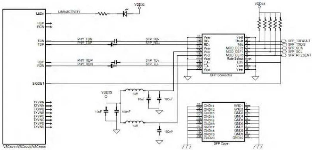
- Connect the PHY's RD output pins to the TD input pins of the SFP connector.
-
Connect the PHY's TD input pins to the RD output pins of the SFP connector.
-
The RD and TD traces must be targeted to be 50-ohm impedance traces and be routed as a differential pairs.
- Connect the PHY's SIGDET input pin to the LOS output pin of the SFP connector.
- Set MII Register 19E.0 = 1 to set the SIGDET pin to 'active-low'. This will set the pin to properly receive the LOS behavior without additional glue logic.
- The SFP's Present, SCL, SDA, TX_DIS, and TX_FAULT signals may be connected to the Switch/MAC/ASIC. If using multiple SFPs, it may be best to implement an I2C controller as all SFP devices have an I2C address = 00000.
- Leave the PHY's RC output clock pins as 'no-connect'.
- Leave the copper media interface as 'no-connect'.
- Use one of the PHY's LED pins, select LINK/ACTIVITY, and connect it to the CATHODE pin of an LED. This can be used to indicate when the SFP is linked and has data activity present.
• Depending on certain SFPs, the 0.1uF AC coupling capacitors may not be needed.
• All pull-up resistors should have a value between 4.7K to 10K ohms.
Figure 3 • SimpliPHY to SFP Reference Schematic
text_image
LEDn LINK/ACTIVITY VDD33 RCP HCN TDN TDP PHY TDN PHY TOP SFP RD- SFP RD+ 11 12 13 14 15 16 17 18 19 20 Vccr RD- RD+ Vccr Vccr Vccr Vccr Vccr Vccr Vccr Vccr Vccr Vccr Vccr Vccr Vccr Vccr Vccr Vccr Vccr Vccr Vccr Vccr Vccr Vccr Vccr Vccr Vccr Vccr TTXFAULT SFP TXDIS SFP SDA SFP SCL SFP PRESENT RDP RDN PHY ROP PHY RDN SFP TD+ SFP TD- 10uF 10uF 10uF 10uF 10uF 10uF 10uF 10uF 10uF 10uF 10uF 10uF 10uF 10uF 10uF 10uF 10uF 10uF 10uF 10uF 10uF 10uF 10uF 10uF 10uF 10uF 10uF 10uF 10uF 10uF 10uF 10uF 10uF 10uF 10uF 10uF 10uF 10uF 10uF 10uF 10uF SIGDET TXVPA TXVNA TXVPB TXVN8 TXVPC TXVNC TXVPD TXVND VDD33 VDD33 SFP Connector GND11 GND2 GND3 GND4 GND5 GND6 GND7 GND8 GND9 GND10 GND11 GND12 GND13 GND14 GND15 GND16 GND17 GND18 GND19 GND20 GND21 VSC821+VSC822+VSC85585.4 Connecting to 100BASE-FX Fiber SFPs
100BASE-FX support details for each relevant PHY listed in Table 3 are described in their 'Supporting 100BASE-FX Fiber Media' application notes. The below explanation is based on the VSC8538/VSC8538 example using Copper media pins. For the VSC8658 which uses the SerDes pins, refer to Section 4.3 as this interface supports 1000BASEX, 100BASE-FX, and 10/100/1000BASE-T Copper SFPs using the same board design.
To connect a SimpliPHY device to a 100BASE-FX Fiber SFP, please use the following guidelines and reference schematic.
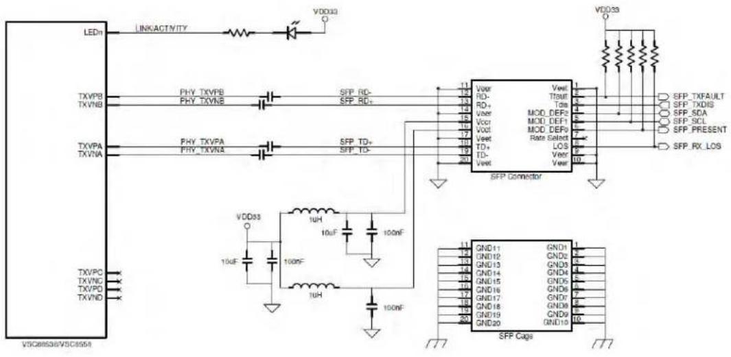
- Connect the PHY's TXVPA and TXVNA pins to the TD input pins of the SFP connector.
- Connect the PHY's TXVPB and TXVNB pins to the RD output pins of the SFP connector.
- Leave the TXVPC, TXVNC, TXVPD, and TXVND pins as 'no-connect'.
- The RD and TD traces must be targeted to be 50-ohm impedance traces and be routed as a differential pairs.
- The SFP's Present, SCL, SDA, TX_DIS, TX_FAULT, and RX_LOS signals may be connected to the Switch/MAC/ASIC or the GPIO pins of the VSC8538/58. If using multiple SFPs, it may be best to implement an I2C controller as all SFP devices have an I2C address = 00000.
- Use one of the PHY's LED pins, select LINK/ACTIVITY or LINK100/ACTIVITY, and connect it to the CATHODE pin of an LED. This can be used to indicate when the SFP is linked and has data activity present.
• Depending on certain SFPs, the 0.1uF AC coupling capacitors may not be needed.
• All pull-up resistors should have a value between 4.7K to 10K ohms.
- To configure a PHY for 100BASE-FX operating mode, please use the following table in association with the VSC8538/58 datasheet. The GPIO Register 18 is located on the GPIO register page, which is accessed via Register 31.
Figure 4 • SimpliPHY to 100BASE-FX Reference Schematic
text_image
LEDn LINKACTIVITY VDD032 TXVPB TXVNB PHY_TXVPB PHY_TXVNB SFP_RD- SFP_RD+ 11 12 13 14 15 16 17 18 19 20 Vdd33 SFP TXFAULT SFP_TXDIS SFP_SDA SFP_SCL SFP_PRESENT SFP_RX_LOS TXVPA TXVNA PHY_TXVPA PHY_TXVNA SFP_TD+ SFP_TD- SFP Connector Vdd033 10uF 10uF 10uF 10uF 10uF 10uF 10uF 10uF 10uF 10uF 10uF 10uF 10uF 10uF 10uF 10uF 10uF GND11 GND12 GND13 GND14 GND15 GND16 GND17 GND18 GND19 GND20 GND10 SFP CapsTable 3 • 100BASE-FX Control – GPIO Register 18 (0x12)
| Bit Name Mode Description Default | |||
| 15 Activate 100BASE-FX R/W 0 = No action | 0 | ||
| 1 = Activate 100BASE-FX based on bits 11:0 | |||
| 14: | Reserved RO 000 | ||
| 12 | |||
| 11 100BASE-FX on all PHYs | R/W 0 = No 100BASE-FX on all PHYs | 0 | |
| 1 = Configure 100BASE-FX on all PHYs when Register 18.15 = 1 | |||
| 10: | Individual 100BASE- | R/W PHY Number to enable 100BASE-FX when Register 18.15 = 1 000 | |
| 8 | FX setting | ||
| 7:0 100BASE-FX mode R/W 0x00 = No 100BASE-FX | 000 | ||
| 0x01 = 100BASE-FX mode when Register 18.15 = 1 | |||
| 0x02 - 0xFF = reserved | |||
Example: To configure all PHYs to 100BASE-FX, ensure Bit 15 = 0 and set Bit 11 = 1 and Bits 7:0 = 0x01, then set Bit 15 = 1 to activate 100BASE-FX on all PHYs.
To configure an individual PHY to 100BASE-FX, ensure Bit 15 = 0 and set Bits 10:8 to the correct PHY number to be configured for 100BASE-FX and also set Bits 7:0 = 0x01, then set Bit 15 = 1 to activate 100BASE-FX on the specified PHY. Repeat macro for each individual PHY.
6 Connecting to Dual Media Designs
Vitesse SimpliPHY's VSC8211, VSC8224, VSC8234, VSC8558, and VSC8658 devices can be used to support dual media (copper and fiber) in specific applications. Please refer to the following sub-sections for more information.
6.1 VSC8211 Dual Media
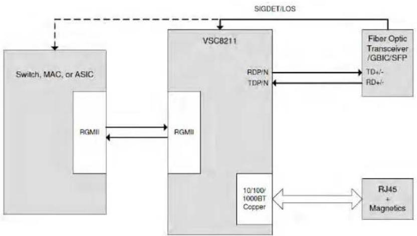
The VSC8211 can support automatic dual media without software management intervention when using an RGMII MAC interface. The VSC8211's Auto-Media Sense™ capability allows the VSC8211 to actively select between copper and fiber based on detecting activity on both media ports. To prevent media contention, fiber or copper preference can be set during initialization. Please see the VSC8211 datasheet for more information.
Figure 5 • Dual Media Using VSC8211 (RGMII MAC Interface)
flowchart
graph TD
    A["Switch, MAC, or ASIC"] -->|RGMII| B["VSC8211"]
    B -->|RDP/N TDP/N| C["Fiber Optic Transceiver / GBIC/SFP"]
    B --> D["RJ45 + Magnetics"]
    B --> E["10/100/1000BT Copper"]
    C --> F["TD+/- RD+/-"]
    B --> G["SIGDET/LOS"]
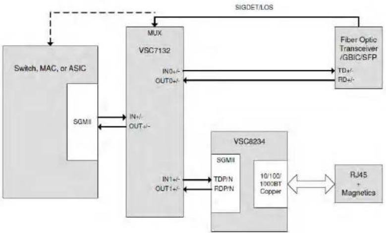
A VSC8211 can also be used to support an SGMII MAC interface to dual media applications. The MAC /Switch/ASIC polls the Loss of Signal from a 10/100/1000BASET Copper SFP. If Loss of Signal (LOS) is de-asserted, valid data could be present on SerDes media and the monitor needs to set the VSC8211 PHY in SGMII to SerDes media operating mode. If Signal Detect is de-asserted, the polling application needs to set the VSC8211 to SGMII to copper media operating mode. The operating mode of the VSC8211 is set by writing to MII Register 23 using the MDC/MDIO management interface of the PHY. After a Register 23 write, the port will need a software reset (MII Register 0.15 = 1) for the operating mode change to take effect. After this is done the software initialization will have to be re-run (unless the MII registers are marked as "Sticky").
Figure 6 • Dual Media Using VSC8211 (SGMII MAC Interface)
flowchart
graph TD
    A["Switch, MAC, or ASIC"] -->|SIGMII| B["MUX"]
    B -->|IN0+/-/OUT0+/-| C["Fiber Optic Transceiver /GBIC/SFP"]
    B -->|IN1+/-/OUT1+/-| D["VSC8234"]
    D -->|IN0+/-/1000BT Copper| E["RJ45 + Magnetics"]
    D --> F["SGMII TDP/N RDP/N"]
    C --> G["TD+/- RD+/-"]
    style A fill:#f9f,stroke:#333
    style B fill:#ccf,stroke:#333
    style C fill:#cfc,stroke:#333
    style D fill:#fcc,stroke:#333
    style E fill:#cff,stroke:#333
    style F fill:#ffc,stroke:#333
    style G fill:#fcc,stroke:#333
6.2 VSC8224 Dual Media
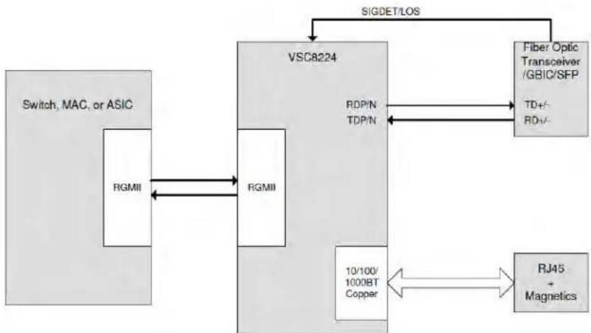
The VSC8224 can support automatic dual media without software management intervention. The VSC8224's Auto-Media Sense capability allows the VSC8224 to actively select between copper and fiber based on detecting activity on both media ports. To prevent media contention, fiber or copper preference can be set during initialization. Please see the VSC8224 datasheet for more information.
Figure 7 • Dual Media Using VSC8224 (only one port shown)
flowchart
graph TD
    A["Switch, MAC, or ASIC"] -->|RGMII| B["VSC8224"]
    B -->|SIGDET/LOS| C["Fiber Optic Transceiver /GBIC/SFP"]
    B -->|RDP/N TDP/N| D["RJ45 + Magnetics"]
    B -->|10/100/1000BT Copper| E["10/100/1000BT Copper"]
    C -->|TD+/- RD+/-| B
6.3 VSC8234 Dual Media
In multi-port dual media applications requiring an SGMII MAC interface, a VSC8234 can be connected to a SerDes link port replicator such as the VSC7132 (single port replicator) or VSC7142 (dual port replicator). The Signal Detect of a fiber optical transceiver or the LOS signal of an SFP/GBIC can be used by the VSC7132/42 and/or Switch/MAC/ASIC for selecting copper or fiber media data. No software configuration needs to take place on the VSC8234 unless it is required to drop the copper link when the fiber link is active. To do this, poll the Signal Detect with the switch/MAC/ASIC. Once Signal Detect is asserted, set the VSC8234's PHY port power down bit (MII Register 0.11 = 1). If Signal Detect is de-asserted, it is important to disable the power down bit within the VSC8234 to allow the copper media to become active.
When the fiber interface is used, the VSC7132/42 only links the fiber media interface to the Switch, MAC, or ASIC. In this case, 1000BASE-X auto-negotiation or SGMII auto-negotiation to the fiber-optic transceiver, GBIC, or SFP must be performed by the Switch, MAC, or ASIC.
Figure 8 • Dual Media Using VSC8234 (only one port shown)

flowchart
graph TD
    A["Switch, MAC, or ASIC"] --> B["MUX"]
    B --> C["Fiber Optic Transceiver / GBIC/SFP"]
    B --> D["VSC7132"]
    D --> E["SIGDET/LOS"]
    B --> F["VSC8234"]
    F --> G["RJ45 + Magnetics"]
    F --> H["10/100/1000BT Copper"]
    F --> I["SGMII TDP/N RDP/N"]
    B --> J["IN+/- OUT+/-"]
    B --> K["IN-/- OUT-/-"]
    B --> L["IN+/- OUT+/-"]
    B --> M["IN-/- OUT-/-"]
    B --> N["SGMII"]
6.4 VSC8558 Dual Media
The VSC8558 can support automatic dual media without software management intervention. The VSC8558's Auto-Media Sense™ capability allows the VSC8558 to actively select between copper and SerDes media (1000BASE-X fiber or 10/100/1000BASE-T Copper SFPs) based on detecting activity on both media ports. To prevent media contention, SerDes media or copper media preference can be set during initialization. Please see the VSC8558 datasheet for more information.
Figure 9 • Dual Media Using VSC8558 (only one port shown)

flowchart
graph TD
    A["Switch, MAC, or ASIC"] --> B["VSC855B"]
    B --> C["Fiber Optic XCVR/GBIC/SFP of 10/100/1000BASE-T Copper SFP"]
    B --> D["10/100/1000BT Copper"]
    B --> E["RJ45 + Magnetics"]
    F["SGMII"] --> G["TDP/N RDP/N"]
    G --> B
    H["SDOP/N SDIP/N"] --> B
    I["SIGDET/LOS"] --> B
    J["TD+/- RD+/-"] --> B
    K["SGMII"] --> L["TDP/N RDP/N"]
    M["10/100/1000BT Copper"] --> N["10/100/1000BT Copper"]
    O["10/100/1000BT Copper"] --> P["10/100/1000BT Copper"]
6.5 VSC8658 Dual Media
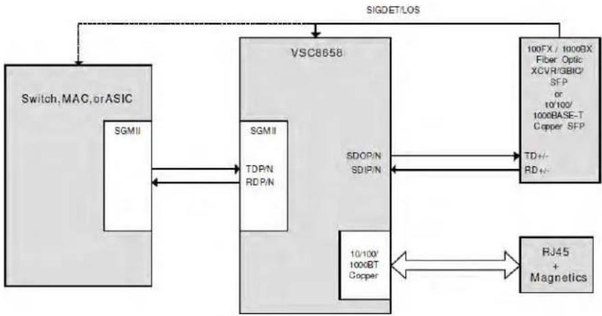
The VSC8658 can support automatic dual media without software management intervention. The VSC8658's Auto-Media Sensetr capability allows the VSC8658 to actively select between copper and SerDes media (1000BASE-X fiber, 100BASE-FX fiber, or 10/100/1000BASE-T Copper SFPs) based on detecting activity on both media ports. To prevent media contention, SerDes media or copper media preference can be set during initialization. Please see the VSC8658 datasheet for more information.
Figure 10 • Dual Media Using VSC8658 (only one port shown)
flowchart
graph TD
    A["Switch, MAC, or ASIC"] --> B["VSC8658"]
    B --> C["100FX / 1000DX Fiber Optic XCVR/GBIC/SFP or 10'100/1000BASE-T Copper SFP"]
    B --> D["10/100' 1000BT Copper"]
    B --> E["RJ45 + Magnetics"]
    F["SGMII"] --> B
    G["SDOP/N SDIP/N"] --> B
    H["SGMII TDP/N RDP/N"] --> B
    I["SIGDET/LOS"] --> B
    J["TD+/- RD+/-"] --> B
    K["10/100' 1000BT Copper"] --> B
6.6 VSC8664 Dual Media
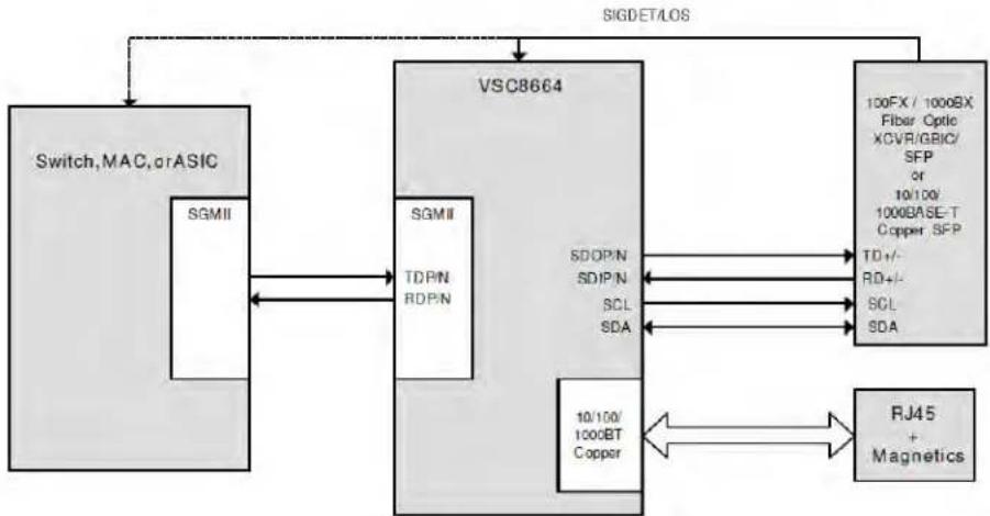
The VSC8664 can support automatic dual media without software management intervention. The VSC8664's Auto-Media Sense™ capability allows the VSC8664 to actively select between copper and SerDes media (1000BASE-X fiber, 100BASE-FX fiber, or 10/100/1000BASE-T Copper SFPs) based on detecting activity on both media ports. To prevent media contention, SerDes media or copper media preference can be set during initialization.
In addition, the VSC8664 has an integrated I2C mux functionality for reading and writing the SFP directly through the VSC8664's MDC/MDIO pins. This essentially eliminates the need for an external I2C mux or wasting pins on the CPU, switch, or a programmable logic device. Please see the VSC8664 datasheet for more information.
Figure 11 • Dual Media using VSC8664 (only one port shown)
flowchart
graph TD
    A["Switch, MAC, or ASIC"] -->|SIGDET/LOS| B["VSC8664"]
    B -->|SOMI| C["SGMII"]
    B -->|TDPN| D["SGMII"]
    B -->|RDPN| E["SGMII"]
    B -->|SDIPN| F["SDOPN"]
    B -->|SDIPN| G["SDIPN"]
    B -->|SCL| H["SCL"]
    B -->|SDA| I["SCL"]
    B -->|10/100/1000BT Copper| J["10/100/1000BT Copper"]
    B --> K["RJ45 + Magnetics"]
    B --> L["100FX / 1000BX Fiber Optic XCVR/GBIC/SFP or 10/100/1000BASE-T Copper SFP"]
    L --> M["TD+/- RD+/- SCL SDA"]

Microsemi.
a MICROCHIP company
Microsemi Headquarters
One Enterprise, Aliso Viejo,
CA 92656 USA
Within the USA: +1 (800) 713-4113
Outside the USA: +1 (949) 380-6100
Sales: +1 (949) 380-6136
© 2005 Microsemi. All rights reserved. Microsemi and the Microsemi logo are trademarks of Microsemi Corporation. All other trademarks and service marks are the property of their respective owners.
Microsemi makes no warranty, representation, or guarantee regarding the information contained herein or the suitability of its products and services for any particular purpose, nor does Microsemi assume any liability whatsoever arising out of the application or use of any product or circuit. The products sold hereunder and any other products sold by Microsemi have been subject to limited testing and should not be used in conjunction with mission-critical equipment or applications. Any performance specifications are believed to be reliable but are not verified, and Buyer must conduct and complete all performance and other testing of the products, alone and together with, or installed in, any end products. Buyer shall not rely on any data and performance specifications or parameters provided by Microsemi. It is the Buyer's responsibility to independently determine suitability of any products and to test and verify the same. The information provided by Microsemi hereunder is provided "as is, where is" and with all faults, and the entire risk associated with such information is entirely with the Buyer. Microsemi does not grant, explicitly or implicitly, to any party any patent rights, licenses, or any other IP rights, whether with regard to such information itself or anything described by such information. Information provided in this document is proprietary to Microsemi, and Microsemi reserves the right to make any changes to the information in this document or to any products and services at any time without notice.
Microsemi, a wholly owned subsidiary of Microchip Technology Inc. (Nasdaq: MCHP), offers a comprehensive portfolio of semiconductor and system solutions for aerospace & defense, communications, data center and industrial markets. Products include high-performance and radiation-hardened analog mixed-signal integrated circuits, FPGAs, SoCs and ASICs; power management products; timing and synchronization devices and precise time solutions, setting the world's standard for time; voice processing devices; RF solutions; discrete components; enterprise storage and communication solutions; security technologies and software; anti-lamper products; Ethernet solutions; Power-over-Ethernet ICs and midspans; as well as custom design capabilities and services. Microsemi is headquartered in Aliso Viejo, California, and has approximately 4,800 employees globally. Learn more at www.microsemi.com.
VPPD-01190