USB2503A - Electronic component Microchip - Free user manual and instructions
Find the device manual for free USB2503A Microchip in PDF.

User questions about USB2503A Microchip
0 question about this device. Answer the ones you know or ask your own.
Ask a new question about this device
Download the instructions for your Electronic component in PDF format for free! Find your manual USB2503A - Microchip and take your electronic device back in hand. On this page are published all the documents necessary for the use of your device. USB2503A by Microchip.
USER MANUAL USB2503A Microchip
EVB-USB2503 Evaluation Board

natural_image
Green printed circuit board with various electronic components and connectors (no readable text or symbols)Copyright © 2007 SMSC or its subsidiaries. All rights reserved.
The information contained herein is proprietary to SMSC and shall be used solely in accordance with the agreement pursuant to which it is provided. Although the information is believed to be accurate, no responsibility is assumed for inaccuracies. SMSC reserves the right to make changes to this document and to specifications and product descriptions at any time without notice. Neither the provision of this information nor the sale of the described semiconductor devices conveys any licenses under any patent rights or other intellectual property rights of SMSC or others unless specifically specified otherwise. The product may contain design defects or errors known as anomalies, including but not necessarily limited to any which may be identified in this document, which may cause the product to deviate from published specifications. SMSC products are not designed, intended, authorized or warranted for use in any life support or other application where product failure could cause or contribute to personal injury or severe property damage. Any and all such uses without prior written approval of an officer of SMSC will be fully at the risk of the customer. SMSC is a registered trademark of Standard Microsystems Corporation ("SMSC").
SMSC DISCLAIMS AND EXCLUDES ANY AND ALL WARRANTIES, INCLUDING WITHOUT LIMITATION ANY AND ALL IMPLIED WARRANTIES OF MERCHANTABILITY, FITNESS FOR A PARTICULAR PURPOSE, TITLE, AND AGAINST INFRINGEMENT AND THE LIKE, AND ANY AND ALL WARRANTIES ARISING FROM ANY COURSE OF DEALING OR USAGE OF TRADE. IN NO EVENT SHALL SMSC BE LIABLE FOR ANY DIRECT, INCIDENTAL, INDIRECT, SPECIAL, PUNITIVE, OR CONSEQUENTIAL DAMAGES; OR FOR LOST DATA, PROFITS, SAVINGS OR REV-ENUES OF ANY KIND: REGARDLESS OF THE FORM OF ACTION, WHETHER BASED ON CONTRACT; TORT; NEGLIGENCE OF SMSC OR OTHERS; STRICT LIABILITY; BREACH OF WARRANTY; OR OTHERWISE; WHETHER OR NOT ANY REMEDY OF BUYER IS HELD TO HAVE FAILED OF ITS ESSENTIAL PURPOSE, AND WHETHER OR NOT SMSC HAS BEEN ADVISED OF THE POSSIBILITY OF SUCH DAMAGES.
1 Overview
1.1 Features
- Operates from a single voltage (+5.0V, regulated) wall wart external power supply or bus-powered from upstream VBUS
- Onboard +3.3V Regulator (Option A linear, Option B switching regulator)
■ Self-powered or bus-powered operation dynamically switched - Serial EEPROM for configuration information mounted in a socket
■ Optional pull-up resistors for disabling individual downstream ports
■ Green LED indicators
■ Individual port over-current sense and power switching
■ Multi-TT enabled
■ High-speed/Full-speed capable
■ 100mS down stream port power on time
■ PCB - 2.6" X 3.5", 4-layers
1.2 General Description
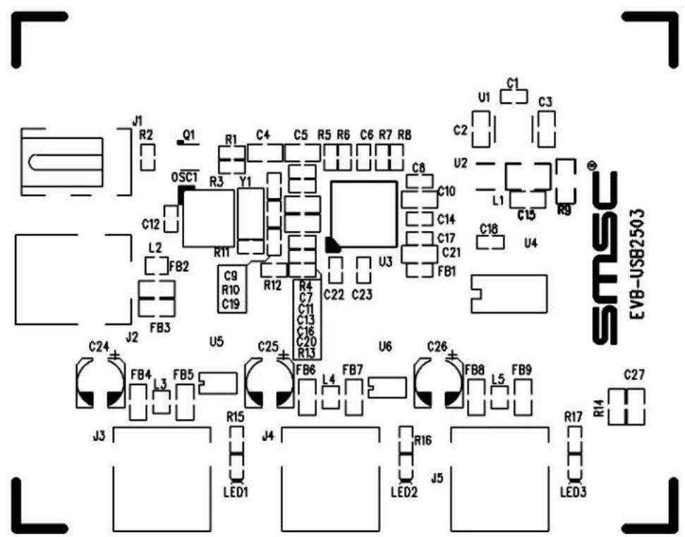
The primary purpose of this board is to demonstrate a full-featured HUB configuration for the SMSC USB2503 3-port HUB. This does not represent a minimal cost design. A view of the silk screen is shown in figure 1. The EEPROM allows for modifications to the base configuration - for example one or more down stream ports can be disabled or configured as non-removable for compound device application. The DID, PID or DID information can be changed for the HUB.
2 Hardware Functionality
2.1 Dynamic Power Switching
The EVB-USB2503 supports dynamic switching of power. This feature allows a hub to operate as self-powered when external power is available or bus-powered when external power is not available. The USB2503 will reconfigure when it detects pin SELF_PWR changing. For more details on dynamic power switching feature please refer to the data sheet for the USB2503.
2.1.1 Regulator Options
The EVB-USB2503 supports two different 3.3V regulator solutions A and B. Option A uses a standard LDO regulator. For true USB-IF certifiable bus power operation the total power budget exceeds the maximum allowed. However, option B uses a switching regulator with approximately 90% efficiency. This regulator also has a low suspend current feature. The power budget is shown in the table below for different operating conditions. The hub controller current is the maximum current when all three down stream ports are operating.
NOTE:
For reference revision A3 of the schematic in included and is recommended for new designs. The EVB-USB2503 is shipping as revision A2 and does not incorporate the changes from A2 to A3.
2.1.2 Power Budget
Table 1 Power Budget
| HUB CONTROLLER | DOWNSTREAM PORTS TOTAL | ||
| SELF POWERED | |||
| Linear Regulator, Option A 250 mA 1500 mA 1750 mA | |||
| Switching regulator, Option B 170 mA 1500 mA 1670 mA | |||
| Bus Powered | |||
| Linear regulator, Option A 250 mA 300 mA 550 mA | (Note this exceeds USB-IF specification for bus-powered devices, which is 500 mA maximum) | ||
| Switching regulator, Option B 170 mA 300 mA 470 mA | |||
| Suspend | |||
| Linear regulator, Option A | 1.2 mA | 1.5 mA | 2.7 mA |
| Switched regulator, Option B | 0.9 mA | 1.5 mA | 2.4 mA |
text_image
J1 R2 Q1 R1 C4 C5 R5 R6 C6 R7 R8 U1 C1 C3 C2 0SC1 Y1 C8 U2 L1 C15 R9 C12 R11 C10 C14 C17 C21 FB1 L2 FB2 C9 R10 C19 R12 C22 C23 U3 C18 U4 FB3 J2 U5 C25 C7 C11 C13 C16 C20 R13 C24 FB4 3 FB5 FB6 L4 FB7 U6 C26 FB8 L5 FB9 J3 R15 J4 LED1 R16 J5 LED2 R17 LED3 C27 EVB-USB2503Figure 2.1 Silk screen of EVB-USB2503 PCB.
2.1.3 EEPROM Configuration
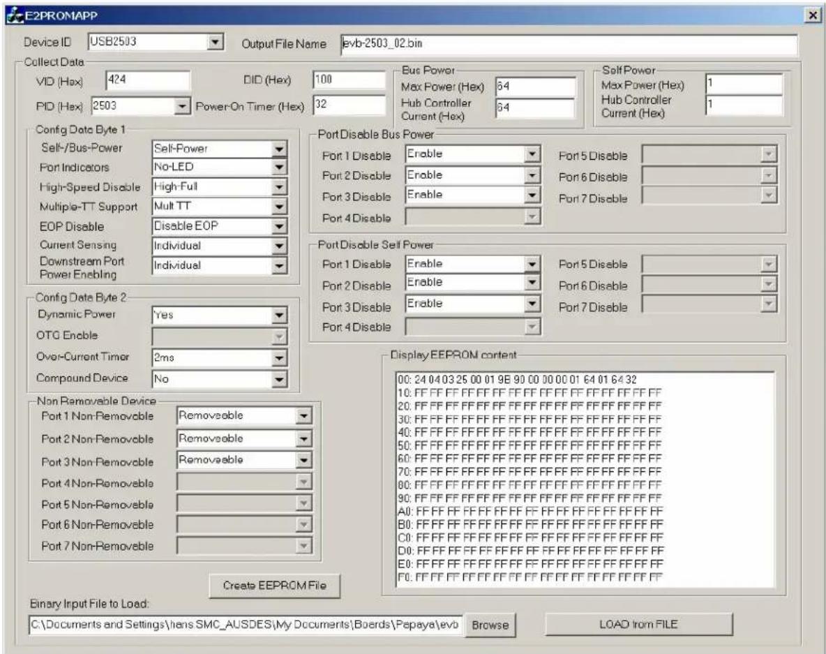
The windows utility E2PROMAPP is included in the package to allow modifications of the base configuration EEPROM. The bin file evb-usb2503_02.bin contains the base configuration. A screen shot from the application is shown in figure 2. After changes has been selected click the button "Create EEPROM File". Note that if the output file name is the same as the input file name it will be overwritten with the new values. The output file name can be changed before creating a new bin file. The bin file format is compatible with most EEPROM programmers.
text_image
E2PROMAPP Device ID USB2503 Output File Name evb-2503_02.bin Collect Data VID (Hex) 424 DID (Hex) 100 Bus Power Max Power (Hex) 64 Self Power Max Power (Hex) 1 PID (Hex) 2503 Power-On Timer (Hex) 32 Hub Controller Current (Hex) Hub Controller Current (Hex) Config Data Byte 1 Self-/Bus-Power Self-Power Port 1 Disable Port 5 Disable Port Indicators No-LED Port 2 Disable Port 6 Disable High-Speed Disable High Full Port 3 Disable Port 7 Disable Multiple-TT Support Mult TT Port 4 Disable EOP Disable Disable EOP Current Sensing Individual Downstream Port Individual Power Enabling Config Data Byte 2 Dynamic Power Yes Port 1 Disable Port 5 Disable OTG Enable Port 2 Disable Port 6 Disable Over-Current Timer 2ms Port 3 Disable Port 7 Disable Compound Device No Port 4 Disable Non Removable Device Removeable Port 1 Non-Removable Removeable Port 2 Non-Removable Removeable Port 3 Non-Removable Removeable Port 4 Non-Removable Port 5 Non-Removable Port 6 Non-Removable Port 7 Non-Removable Display EEPROM content Binary Input File to Load: C:\Documents and Settings\hens SMC_AUSDES\My Documents\Boards\Pepaya\evo Browse LOAD from FILEFigure 2.2 E2PROMAPP EEPROM Configuration Utility.