TMC2072 - Electronic component Microchip - Free user manual and instructions
Find the device manual for free TMC2072 Microchip in PDF.

User questions about TMC2072 Microchip
0 question about this device. Answer the ones you know or ask your own.
Ask a new question about this device
Download the instructions for your Electronic component in PDF format for free! Find your manual TMC2072 - Microchip and take your electronic device back in hand. On this page are published all the documents necessary for the use of your device. TMC2072 by Microchip.
USER MANUAL TMC2072 Microchip
CircLink™ EVB Software Operation Manual
1 Overview
This manual explains how to install and operate the CircLink™ EVB Software. This software is used to control a TMC2084 IO Node from a TMC2074 Host Node. This software was written using Visual Studio VC++ 6.0 and is intended to run on a PC with a Windows 2000 or Windows XP operating system. This software does not use interrupt handling. Editing this software requires a Visual Studio VC++ 6.0 development environment. Correct operation of this software requires a CircLink evaluation environment consisting of the following:
■ Exactly one host node, consisting of a PCM-2074 evaluation board with TMC2074 Dual Mode CircLink Controller installed.
At least one IO node, consisting of an EVB-2084 evaluation board with TMC2084 IO Node CircLink Controller installed. The CircLink™ EVB Software comes configured for two IO nodes.
This application does not access the PCM-2074 directly, but indirectly through a device driver. For instructions on installation of this device driver, refer to Chapter 4.
1.1 Software File Listings
The CircLink™ EVB Software is shipped on one disk, consisting of the files outlined in Table 1.1 below:
Table 1.1 CircLink™ EVB Software Installation Disks
| ITEM FILE/FOLDER NAME CONTENTS NOTES | |||
| 1 <EcTest2000> Source files VC++ 6.0 | |||
| 2 EcTest.EXE Executable file | |||
| 3 | EcNetPcm.inf | INF File for PCM-2074 Device Driver (Win2000/XP) | |
| 4 | CLIoDRV.sys | PCM-2074 Device Driver (Win2000/XP) | |
Table 1.2 below lists all of the source and header files associated with the CircLink™ EVB Software.
Table 1.2 CircLink™ EVB Software Source Files
| ITEM | FILE NAME | CONTENTS | NOTES |
| 1 | EcDriverIF.cpp | Device driver I/F function | |
| 2 | Ecnet.cpp | CircLink related functions | |
| 3 | EcTest.cpp | Visual Studio auto-generation file | |
| 4 | EcTestDlg.cpp | Main dialogs of sample program | |
| ITEM | FILE NAME CONTENTS | NOTES | |
| 5 Host | Set.cpp Host (PCM-2074) configuration dialog | ||
| 6 IoSet | .cpp I/O Node (EVB-2084) configuration dialog | ||
| 7 Memory | .cpp Host (PCM-2074) memory dialog | ||
| 8 StdAfx | .cpp Visual Studio auto-generation file | ||
| 9 EcDemo.h | Demo sample data Demo1, Demo2 | ||
| 10 Ecnet.h | Header file for CircLink | ||
| 11 | EcnetReg.h | Header file for CircLink | |
| 12 | EcTest.h | Visual Studio auto-generation file | |
| 13 | EcTestDlg.h | Visual Studio auto-generation file | |
| 14 | HostSet.h | Visual Studio auto-generation file | |
| 15 | IoSet.h | Visual Studio auto-generation file | |
| 16 | Memory.h | Visual Studio auto-generation file | |
| 17 | Resource.h | Visual Studio auto-generation file | |
| 18 StdAfx.h | Visual Studio auto-generation file | ||
Table 1.3 below shows the project files automatically generated by Visual Studio. Editing the following files may cause the software not to run correctly; please do not edit them.
Table 1.3 CircLink™ EVB Software Source Files
| ITEM | FILE NAME CONTENTS | NOTES | |
| 1 | EcTest.aps | Visual Studio auto-generation file | |
| 2 | EcTest.ncb | Visual Studio auto-generation file | |
| 3 EcTest.opt Visual Studio auto-generation file | |||
| 4 | EcTest.dsp | Visual Studio auto-generation file | |
| 5 | EcTest.dsw | Visual Studio auto-generation file | |
| 6 | EcTest.rc | Visual Studio auto-generation file | |
| 7 EcTest.clw Visual Studio auto-generation file | |||
| 8 | Resource.hm | Visual Studio auto-generation file | |
2 Operating Instructions
Operating instructions for the CircLink™ EVB Software are described below. The screenshots are from Windows 2000; however, they apply to Windows XP as well.
2.1 Starting the CircLink ^TM EVB Software
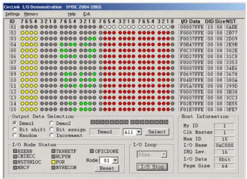
The CircLink™ EVB Software is started by invoking EcTest.exe. The screen shown in Figure 2.1 is displayed, showing that the CircLink™ EVB Software has started and is in the idle/configuration state. This screen is the Main Screen for the CircLink™ EVB Software. From this screen, the host and IO nodes can be configured, along with CircLink™ EVB Software operational parameters.

text_image
CircLink I/O Demonstration SMSC 2004-2005 Settings Memory Help Exit ID 7 6 5 4 3 2 1 0 7 6 5 4 3 2 1 0 7 6 5 4 3 2 1 0 7 6 5 4 3 2 1 0 I/O Data DID SizeNST 01 ●●●● ●●●● ●●●● ●●●● ●●●● ●●●● ●●●● ●●●● ●●●● 02 ●●●● ●●●● ●●●● ●●●● ●●●● ●●●● ●●●● ●●●● ●●●● ●●●● 03 ●●●● ●●●● ●●●● ●●●● ●●●● ●●●● ●●●● ●●●● ●●●● ●●●● 04 ●●●● ●●●● ●●●● ●●●● ●●●● ●●●● ●●●● ●●●● ●●●● ●●●● 05 ●●●● ●●●● ●●●● ●●●● ●●●● ●●●● ●●●● ●●●● ●●●● 06 ●●●● ●●●● ●●●● ●●●● ●●●● ●●●● ●●●● ●●●● ●●●● 07 ●●●● ●○○○○○○○○○○○○○○○○○○○○○○○○○○○○○○○○ 08 ●○○○○○○○○○○○○○○○○○○○○○○○○○○○○○○○○○ 09 ●○○○○○○○○○○○○○○○○○○○○○○○○○○○○○○ 10 ○○○○○○○○○○○○○○○○○○○○○○○○○ 11 ○○○○○○○○○○○○○○○○○○○○○○○○ 12 ○○○○○○○○○○○○○○○○○○○○○○○ 13 ○○○○○○○○○○○○○○○○○○○ 14 ○×××××××××××××××××××××××××××××××××××××××××××××××××××××××××××××××××××××××××××××× Output Data Selection □ Demo1 □ Demo2 □ □ □ □ □ □ □ □ □ □ □ □ □ □ □ □ □ □ □ □ □ □ □ □ □ □ □ □ □ □ □ □ □ □ □ □ □ □ □ □ □ □ □ □ □ □ □ □ □ □ ▢ □ Bit shift □ Bit assign Demol All Select Random □ Increment I/O Node Status □ RXERR □ TKNRETF OPICDONE □ CHIECC □ RCPUN Node 01 □ NSTUNLOC ■POR MRCV ■MYRECON Reset I/O Loop 50ns I/O Start I/O Data 8bit Page Size 64Figure 2.1 Main Screen for CircLink™ EVB Software
The CircLink™ EVB Software is designed to be used with one PCM-2074 Host Node and a maximum of 14 EVB-2084 IO Nodes. The table below shows allowed values for various configuration parameters for the host and IO Nodes. Note that for some parameters, the PCM-2074 has possible values that are not allowed when it is used with EVB-2084 devices.
Table 2.1 Configuration Settings for CircLink Nodes
| NO PARAMETER ALLOWED SETTINGS NOTES | |||
| 1 Node | ID 1-15 (16-31 not allowed) | Each node must have a unique Node ID | |
| 2 Max | ID 1-15 (16-31 not allowed) | Must be the same for all nodes. | |
| 3 | Clock Master ID | 1-15 (16-31 not allowed) | Typically is the host node ID |
| 4 | Page Size | 64 or 128 (32 and 256 not allowed) | Must be the same for all nodes. |
| 5 | Speed | 312.5 Kbps to 5Mbps | Must be the same for all nodes |
2.2 Confirming the Version Level
Clicking Help on the menu bar causes the version of the CircLink™ EVB Software to be displayed as shown in the window below.

text_image
ECTest Version ECTest Version 2.02 Copyright (C) 2004-2006 SMSC URL http://www.smsc.jp http://www.smsc.comFigure 2.2 Software Version Level Window
2.3 Configuring the CircLink ^TM EVB Software to Match the Evaluation Environment
When the CircLink ^TM EVB Software is started, it assumes it has one host node and two IO nodes, configured as shown in Table 2.2. If the nodes are configured differently, follow the configuration steps outlined in Section 2.10 and Section 2.11 to ensure that the configuration assumed by the software matches that actually used by the nodes.
Note: The CircLink™ EVB Software is designed to operate with only one PCM-2074 node; more than one PCM-2074 node may not be added to the network.
Table 2.2 Default Configuration of PCM-2074 Node
| NO PARAMETER PCM-2074 | EVB-2084 #1 EVB-2084 #2 | |||
| 1 Node ID 1 2 3 | ||||
| 2 | M a | x N | o d e | I D |
| 3 Clock Master ID | 1 1 1 | |||
| 4 | Page Size | 64 Bytes/Page | 64 Bytes/Page | 64 Bytes/Page |
| 5 | Speed | 2.5 Mbps | 2.5 Mbps | 2.5 Mbps |
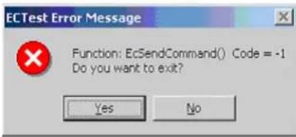
If there is a mis-match between the configuration assumed by the CircLink™ EVB Software and the configuration actually used by the nodes, the error message shown in Figure 2.3 will be displayed. Respond by clicking "No" twice, then follow the configuration steps explained in Section 2.10 and Section 2.11.
text_image
ECTest Error Message Function: EcSendCommand() Code = -1 Do you want to exit? Yes NoFigure 2.3 Error Message if Non-Standard Configuration is Used
2.4 Running the CircLink ™ EVB Software
Clicking the I/O Start button causes the CircLink™ EVB Software to begin running with the Output Data Type that has been chosen in the Output Data Selection. In the example in Figure 2.1 above, "Demo1" has been chosen as the Output Data Type. The Demo1 Output Data Type causes the display to show the status of the inputs and outputs of the host node and all of the IO nodes as shown in Figure 2.4.
When the CircLink™ EVB Software starts running, you will notice that the IO Start button changes to an IO Stop button, and certain configuration windows are grayed out. In general, these parameters can only be changed when the CircLink™ EVB Software is in the idle/configuration state.
text_image
Circlink I/O Demonstration SMSC 2004-2005 Settings Memory Help Exit ID 7654 3210 7654 3210 7654 3210 7654 3210 01 ◆◆◆◆ ◆◆◆◆ ◆◆◆◆ ◆◆◆◆ ◆◆◆◆ ◆◆◆◆ ◆◆◆◆ ◆◆◆◆ ◆◆◆◆ ◆◆◆◆ ◆◆◆◆ ◆◆◆◆ ◆◆◆◆ ◆◆◆◆ ◆◆◆◆ ◆◆◆◆ ◆◆◆◆ ◆◆◆◆ ◆◆◆◆ ◆◆◆◆ ◆◆◆● 02 ◆◆◆ ◆◆◆◆ ◆◆◆◆ ◆◆◆◆ ◆◆◆◆ ◆◆◆◆ ◆◆◆◆ ◆◆◆◆ ◆◆◆◆ ◆◆◆◆ ◆◆◆◆ ◆◆◆◆ ◆◆◆◆ ◆◆◆◆ ◆◆◆◆ ◆◆◆◆ ◆◆◆◆ ◆◆◆◆ ◆◆◆◆ ◆◆◆◆ ◆● 03 ◆◆◆ ◆◆◆◆ ◆◆◆◆ ◆◆◆◆ ◆◆◆◆ ◆◆◆◆ ◆◆◆◆ ◆◆◆◆ ◆◆◆◆ ◆◆◆◆ ◆◆◆◆ ◆◆◆◆ ◆● 04 ◆◆◆ ◆◆◆◆ ◆●●● ◆●●● ◆●●● ◆●●● ◆●●● ◆●●● ◆●●● ◆●●● ◆●●● ◆●●● ◆●●● ◆●●● ◆●●● ◆●●● ◆●●● ◆●●● ◆●●● ◆●●● ◆●●● ◆●●● ◆●●○ 05 ◆◆◆ ◆●○○○○○○○○○○○○○○○○○○○○○○○○○○○○○○○○○○○○○○○○○○○○○○○○○○○○○○○○○○○○○○○○○○○○○○○○○○○○○○○○○○○○○○○○○○○○○○○○○○○○ ○ 06 ◆◆◆ ◆●◇◇◇◇◇◇◇◇◇◇◇◇◇◇◇◇◇◇◇◇◇◇◇◇◇◇◇◇◇◇◇◇◇◇◇◇◇◇◇◇◇◇◇◇◇◇◇◇◇◇◇◇◇◇◇◇◇◇◇◇◇◇◇◇◇◇◇◇◇◇◇◇◇◇◇◇◇◇◇◇◇◇◇◇◇◇◇◇◇◇◇◇◇◇◇◇◇◇◇◇◎ 07 ◆◆◆ ◆●★☆☆☆☆☆☆☆☆☆☆☆☆☆☆☆☆☆☆☆☆☆☆☆☆☆☆☆☆☆☆☆☆☆☆☆☆☆☆☆☆☆☆☆☆☆☆☆☆☆☆☆☆☆☆☆☆☆☆☆☆☆☆☆☆☆☆☆☆☆☆☆☆☆☆☆☆☆☆☆☆☆☆☆☆☆☆☆☆☆☆☆☆☆☆☆☆☆☆☆☆ ☆ 08 ◆◆◆ ◆●★☆☆☆☆☆☆☆☆☆☆☆☆☆☆☆☆☆☆☆☆☆☆☆☆☆☆☆☆☆☆☆☆☆☆☆☆☆☆☆☆☆☆☆☆☆☆☆☆☆☆☆ ☆ 09 ◆◆◆ ◆●★☆☆☆☆☆☆☆☆☆☆☆☆☆☆☆☆☆☆☆☆☆☆☆☆☆☆☆☆☆☆☆☆☆ ☆ 10 ◆◆◆ ◆●★★o o o o o o o o o o o o o o o o o o o o o o o o o o o o o o o o o o o o o o o o o o o o o o o o o o o o o o o o o o o o o o 11 ◆◆◆ ◆●★o o o o o o o o o o o o o o o o o o o o o o o o o o o o o o o o o o o o o o o o o o O 12 ◆◆◆ ◆●★o o o o a a a a a a a a a a a a a a a a a a a a a a a a a a a a a a a a a a a a a a a a a a a a a a a a a a a a a a a a a a a a a a a a A 13 ◆◆◆ ◆●★o o o uo uo uo uo uo uo uo uo uo uo uo uo uo uo uo uo uo uo uo uo uo uo uo uo uo uo uo uo uo uo uo uo uo uo uo uo uo uo uo uo uo uo uo uo uo uo uo uo uo uo u 14 ◆◆◆ ◆●★o o voo voo voo voo voo voo voo voo voo voo voo voo voo voo voo voo voo voo voo voo voo voo voo voo voo voo voo voo voo voo voo voo voo voo voo voo voo voo voo voo voo voo voo voo voo voo voo voo voo voo v oo 15 ◆◆◆ ◆●★o o voo voo voo voo voo voo voo voo voo voo voo voo voo voo voo voo voo voo voo voo voo voo voo voo voo voo voo voo w Output Data Selection ■ Demol ● Demo2 ■ ■ ■ ■ ■ ■ ■ ■ ■ ■ ■ ■ ■ ■ ■ ■ ■ ■ ■ ■ ■ ■ ■ ■ ■ ■ ■ ■ ■ ■ ■ ■ ■ ■ ■ ■ ■ ■ ■ ■ ■ ■ ■ ■ ■ ■ ■ ■ ■ ■ ■ ■ ■ ■ ■ ■ ■ ■ ■ ■ ■ ■ ■ ■ ■ ■ ■ ■ ■ ■ ■ ■ ■ ■ ■ ■ ■ ■ ■ ■ ■ ■ ■ ■ ■ ■ ■ ■ ■ ■ ■ ■ ■ ■ ■ ■ ■ ■ ■ ■ □ ■ Bit shift ● Bit assign Demol All Select ■ Random ● Increment I/O Node Status ■ RXERR ● TKNRETF ● OPICDONE ■ CHIECC ● RCPUM ● Node 01 ■ NSTUNLOC ● POR ■ MRCV ● MYRECON ● Reset I/O Loop 50ms I/O Stop Host Information My ID 1 Clk Master 1 Max ID 15 I/O Base 0xC000 IRQ Lev. 16 I/O Data 8bit Page Size 64Figure 2.4 Display of IO Node Status
Data from the host node (in the case above, Node 1) is displayed in white. Data from the IO nodes is displayed in green, yellow or red depending on its type, as shown in the table below:
Table 2.3 Meaning of IO Node Status Indication Colors
| COLOR MEANING | |
| White Indicates corresponding Host Output is ON. | |
| Red Indicates corresponding IO Node Output is ON | |
| Green Indicates corresponding IO Node Input is ON | |
| Yellow Indicates corresponding IO Node Flag Output is ON | |
| Dark Gray Indicates corresponding Host/IO Node Output/Input is OFF | |
| Light Gray Indicates nodes with Node ID < MAX ID that are not communicating. |
In Figure 2.4 above, Ports A and B are outputs on all IO nodes, with a value of 0x7FFE. The lower bits of Port D are also used as outputs on all IO nodes, with a value of 0x00. The upper bits of Port D are used as Flag Outputs on all nodes, with all flags set. Port C is an input on all IO nodes, but its
value varies from node to node. On Node 2, Port C has a value of 0x00. On Node 3 it has a value of 0x03, on Node 4, or 0xB4, and so on.
2.5 Stopping the CircLink ^TM EVB Software from Running
When the CircLink™ EVB Software is running, it can be stopped by pressing the IO Stop button; this returns it to the idle/configuration state.
2.6 Exiting the CircLink ™ EVB Software
Clicking Exit on the Menu bar causes the message below to be displayed. Clicking OK causes the program to quit; clicking Cancel allows the program to resume.

text_image
ECTest Do you want to finish ? OK CancelFigure 2.5 Exit Confirmation Window
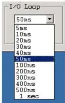
2.7 Setting the Data Transmission Interval
When the CircLink™ EVB Software is in the idle/configuration state, the data transition interval can be set, using the pull-down menu just above the IO Start button. The data transition interval can be set to specified values between 50ms and 1 sec. When the CircLink™ EVB Software is in the Run stat, the data transition pull-down menu is grayed out, and cannot be changed. Figure 2.6 below shows the windows involved with changing the Data Transmission Interval.
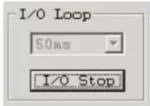
A. Software Running; Data Transmission Interval is grayed out (Cannot be changed)
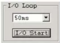
B. Software Idle; Data Transmission Interval can be changed
C. Possible values for Data Transmission Interval (right)
text_image
I/O Loop 50ms 5ms 10ms 20ms 30ms 40ms 50ms 100ms 200ms 300ms 400ms 500ms 1 secFigure 2.6 Configuring the Data Transmission Interval
Notes:
- Selecting either "Host Settings" or "I/O Node Settings" from "Settings" on the menu bar while the software is running causes it to enter the idle/configuration state immediately.
- Selecting a data transmission interval of 5, 10 or 20ms may disable communication depending on PC performance. For slow PCs, settings below 30ms may cause CPU utilization to go above 100%, which can be determined from the Windows task manager by using Ctrl + Shift + Esc.
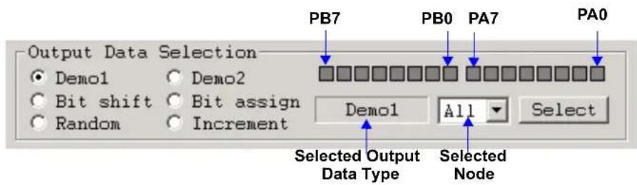
2.8 Selecting the Output Data Type
The CircLink™ EVB Software allows the user to select one of six programs, using the radio buttons under the box labelled "Output Data Selection". Once the selection is made, it has to be confirmed using the Select button. The window for configuring the "DEMO 1" Output Data Type is shown below in Figure 2.7.
text_image
Output Data Selection ● Demo1 ○ Demo2 ○ Bit shift ○ Bit assign ○ Random ○ Increment PB7 PB0 PA7 PA0 Demo1 All Select Selected Output Data Type Selected NodeFigure 2.7 Configuring the "DEMO1" Output Data Type
Table 2.4 below summarizes the six Output Data Types.
Table 2.4 Table of Output Data Types
| NO. TYPE DESCRIPTION | PORTS AFFECTED | ||
| 1 Demo1 16 bits are assigned “Demo Data” pattern A, B | |||
| 2 Demo2 16 bits are assigned to light a 2-digit, 7-segment LED display A, B | |||
| 3 | Bit Assign | 16 bits are manually assigned (see description below) | A, B |
| 4 | Bit Shift | 32-bit shifting pattern (8 bits at a time) | All |
| 5 | Increment | 32-bit incrementing pattern | All |
| 6 Random 32-bit random pattern | All | ||
2.8.1 Using the Bit Assign Output Data Type
Figure 2.8 shows how to assign bits in the Bit Assign Output Data Type. A blue box indicates that the corresponding bit is set to 1; a dark gray box means the corresponding bit is set to 0. In the example below, Ports A and B are both set to "0x55h" respectively. Note that the ON/OFF state is changed by a single click of the left mouse button; double clicking a particular box results in no change of the ON/OFF state.

text_image
Output Data Selection Demo1 Demo2 Bit shift Bit assign Bit assign All Select Random IncrementFigure 2.8 Configuring the "Bit Assign" Output Data Type
2.8.2 Selecting the Output Data Type for a particular target node
The examples so far have shown how to set the Output Data Type for all nodes simultaneously, because the Node ID window is set to All. The Output Data Type can also be set for one node at a time by specifying a particular node in this window, as shown in Figure 2.9 below.

text_image
For MaxID = 4 Output Data Selection Demo1 Demo2 Bit shift Bit assign Demo1 All Select Random Increment I/O Node Status RXERR TKNRETF OPICDONE CMIECC RCPUM NSTUNLOC POR Node 01 MRCV MYRECON Reset Loop 01 02 03 04 I/O StartFigure 2.9 Selecting the Output Data Type for a Particular Node
In order for the output data type to be changed, the Select button must also be clicked. If the Select button is not clicked after a change is made, the change does not take effect. Also if the Node ID of the Host Node is specified in the Node Selection window, data transmission will not take place to the IO nodes.
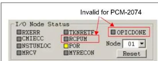
2.9 Displaying Status Information
The IO Node Status Box, located in the lower left-hand corner of the main display window, shows status information pertaining to a particular node that is selected using a pull-down menu. The IO Node Status Box shows the current status for a variety of node parameters; each parameter has its own status button. Yellow indicates that a particular parameter is "1"; gray indicates "0". Figure 2.10 below shows the status window for the Host node at initialization and after reset. Note that two parameters - RCPUM and OPICDONE - are invalid, and can be ignored, in the case of the Host Node.
text_image
Invalid for PCM-2074 I/O Node Status RXERR CMIECC NSTUNLOC MRCV TKNRETF RCPUM POR MYRECON OPICDONE Node 01 ResetA. Status Window after Initialization of a PCM-2074
text_image
I/O Node Status RXERR CMIECC NSTUNLOC MRCV TKNRETF RCPUM POR MYRECON OPICDONE Node 01 ResetB. Status Window after Reset of a PCM-2074
Figure 2.10 Status Windows for the Host Node: A) At Initialization, B) After Reset
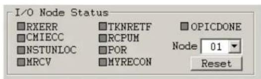
Figure 2.11 below shows the Status Windows for a EVB-2084 IO Node at initialization and after reset.
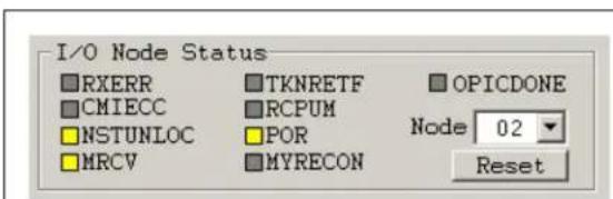
text_image
I/O Node Status RXERR CMIECC NSTUNLOC MRCV TKNRETF RCPUM POR MYRECON OPICDONE Node 02 ResetA. Status Window after Initialization of a EVB-2084

text_image
I/O Node Status RXERR CMIECC NSTUNLOC MRCV TKNRETF RCPUM POR MYRECON OPICDONE Node 02 ResetB. Status Window after Reset of a EVB-2084
Figure 2.11 Status Windows for an IO Node: A) At Initialization, B) After Reset
The meanings of the status window flags are given in Table 2.5 below:
Table 2.5 Meanings of Status Flags
| NO. FLAG MEANING NOTE | |||
| 1 RXERR Error detected during packet reception | |||
| 2 CMIECC Error correction occurred during CMI decoding. | |||
| 3 NSTUNLOC NST was in the unlock state | |||
| 4 MRCV Unicast packet was received normally | |||
| 5 TKNRETF Token retry detected | |||
| 6 | RCPUM | Received packet had a control pointer not = 0x38h or 0x78h. | Not valid for PCM-2074 |
| 7 POR | Hardware or Software Reset occurred | ||
| 8 MYRECON The RECON timer expired. | |||
| 9 | OPICDONE | Output Port Initialization command completed | Not valid for PCM-2074 |
The drop-down menu can be used to change the node for which the status is displayed. Note that the status information for an IO node is not updated until the host node actually communicates with that node. Selecting a non-participating IO node causes all status information to be displayed in yellow.
2.10 Configuring the PCM-2074 Host Node
To configure the Host node, click "Settings" on the menu bar, then select "Host Settings" using the drop down menu. This is shown below in Figure 2.12. The dialog box for the Host Node Settings is then displayed as shown in and Figure 2.13. This dialog box allows the user to change the configuration of the Host Node. Note that if the Host Settings Dialog box is activated while the CircLink™ EVB Software is running, the software will immediately enter the idle state; the START button has to be clicked in order for execution to resume.

text_image
CircLink I/O Demonstration SMSC 2004-2005 Settings Memory Help Exit Host Settings 1 0 7 6 5 4 3 2 1 0 7 6 5 4 IO Node Settings 10.2Figure 2.12 Activating the Host Node Settings Dialog Box
Figure 2.13 below shows the status of the Host Node at the moment the window is created. The window is not updated by the system and does not reflect changes in status that occur after it is created. The status of individual bits/pins is shown through check boxes.
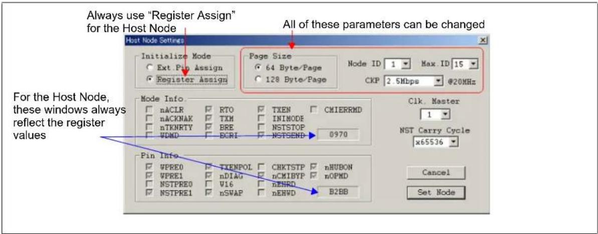
text_image
Always use "Register Assign" for the Host Node All of these parameters can be changed Host Node Settings Initialize Mode Ext Pin Assign Register Assign Page Size 64 Byte/Page 128 Byte/Page Node ID 1 Max. ID 15 CKP 2.5Mbps @20MHz For the Host Node, these windows always reflect the register values Pin Info VPRE0 TXEMPOL CHKTSTP nHUBON VPRE1 nDIAG nCMIBYP nOPMD NSTPRE0 V16 nEHRD NSTPRE1 nSWAP nEHWD B2BB Clk. Master 1 NST Carry Cycle x65536 Cancel Set NodeFigure 2.13 Configuring the Host Node
Referring to the figures above, you will notice in the Initialize Node box that you have a choice between Ext Pin Assign and Register Assign. For a PCM-2074 Host Node, Register Assign is the best choice as shown above, because it allows you to update the Node ID, Max ID and CKP parameters. Once you have made all your configuration changes, click Set Node to have them take effect. To put the CircLink™ EVB Software back in run mode, click the Start Button.
Side effects - note that the Page Size affects the pull-down menu choices for Node ID and Max ID. When the Page Size is set to 64 Bytes/Page, the Node ID and Max ID pull-down windows allow choices of 1 to 15. When the Page Size is set to 128 Bytes/Page, these windows allow choices of 1 to 7. Also the choice of Page Size for the Host Node must match the Page Size set by JP4 on all of the EVB-2084 IO Nodes. Any mismatches will cause communication errors.
Figure 2.14 below shows the configuration window when the Initialize Node box is set to Ext Pin Assign. Note that the Node ID, Max ID and CKP parameters are grayed out and cannot be changed.
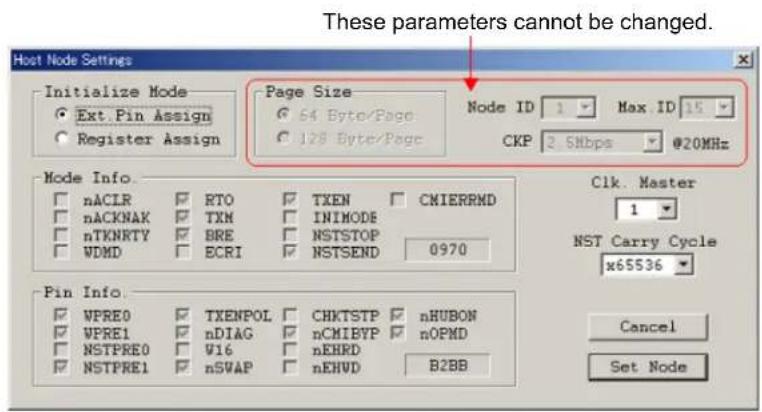
text_image
These parameters cannot be changed. Host Node Settings Initialize Mode Ext.Pin Assign Register Assign Page Size 64 Byte/Page 128 Byte/Page Node ID 1 Max ID 15 CKP 2 Sbps @20MHz Mode Info. nACLR RTO TXEN CMIERRND nACKNAK TXM INIMODE nTKNRTY BRE NSTSTOP WDMD ECRI NSTSEND 0970 Pin Info. WPRE0 TXENPOL CHKTSTP nHUBON WPRE1 nDIAG nCMIBYP nOPND NSTPRE0 W16 nEHRD NSTPRE1 nSWAP nEHVD B2BB Clk. Master 1 NST Carry Cycle x65536 Cancel Set NodeFigure 2.14 Configuring the Host Node in Ext. Pin Assign Mode
2.11 Configuring EVB-2084 IO Nodes
To configure IO nodes, click "Settings" on the menu bar, then select "IO Node Settings" using the drop down menu. This is shown below in Figure 2.15. The dialog box for the Host Node Settings is then displayed as shown in Figure 2.16. This dialog box allows the configuration of the IO Nodes to be changed. Note that if the IO Node Settings Dialog box is activated while the CircLink™ EVB Software is running, the software will immediately enter the idle state; the START button has to be clicked in order for execution to resume.

text_image
CircLink I/O Demonstration SMSC 2004-2005 Settings Memory Help Exit Host Settings 1 0 7 6 5 4 3 2 1 0 7 6 5 4 IO Node Settings 10 2Figure 2.15 Activating the IO Node Settings Dialog Box
The configuration window (below) shows the status of a particular IO Node that is chosen by the IO Node Select pull-down menu. Whenever this pull-down menu is changed, the configuration window is updated with the current configuration of the IO node. The window is not updated after that by the system.
This pull-down changes which IO Node is displayed.
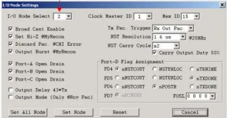
text_image
I/D Node Settings I/O Node Select 2 Clock Master ID 1 Max ID 15 Broad Cast Enable Tx Pac. Trigger Rx Out Pac. Set Hi-Z @MyRecon NST Resolution 1.6 us @20MHz Discard Pac. @CMI Error NST Carry Cycle x2 Output Burst @MyRecon Carry Output Duty 50% Port-A Open Drain Port-D Flag Assignment Port-B Open Drain nNSTCOUT NSTUNLOC nTKN2ME Port-C Open Drain nNSTCOUT NSTUNLOC nTXDONE Output Delay 43*Tx nNSTCOUT nPOSTR nTXDONE Output Mode (Only @Rcv Pac) PD7 nRCMERR FOSL 0 0 0 0 Set All Node Set Node Reset CancelFigure 2.16 Configuring an IO Node
Note that for IO Node, certain parameters such as Node ID and MAX ID are determined by external configuration pins only and cannot be changed via configuration registers. Therefore these parameters cannot be updated using the IO Node Configuration Window shown above. Once you have made all your configuration changes, click Set Node to have them take effect on the node chosen. You can also apply a configuration to all nodes at once by clicking the Set All Node button. The Reset button refreshes the window with the current configuration state of the chosen IO node. Clicking Reset before Set Node or Set All Node will cause any changes you have made to be lost. Clicking Reset after Set Node or Set All Node can be used to confirm that the IO Node reflects the changes you just made. The Cancel button exits the IO Node Configuration Window.
Table 2.6 summarizes the changes that can be made to the I/O Node Configuration.
Table 2.6 Changes that can be made to the IO Node Configuration
| NO NAME DESCRIPTION POSSIBLE VALUES DEFAULT | ||||
| 1 I/O | Node Chooses Node | Displayed in Window 1-15 Lowest ID | ||
| 2 | Clock Master ID | Specifies Node ID of Clock Master | 0-15 (0=Asynchronous) | 1 |
| 3 MAX ID | Specifies MAX ID | 1-15 | 3 | |
| 4 | TX TRIGGER | TXTRG3:0 - Packet Transmit Trigger | 0-F | 0 |
| 5 | NST Resolution | NSTPRE2:0 - NST Resolution | 1.6us to 204.8us | 1.6us |
| 6 | NST Carry Cycle | NST Carry Output Selection | NSTPRE × 2 to NSTPRE × 2^16 | NSTPRE × 2 |
| 7 | Carry Out Duty | 50% Duty Cycle on Carry Output | On/Off | On |
| 8 | Broadcast Enable | Enable/Disable Broadcast Reception | On/Off | On |
| 9 Hi-Z@MyRecon | Output port state when a "MyRecon" event occurs | Tri-state / Hold previous level (high or low) | Tri-state | |
| 10 | Discard Pac@ CMI Error | Packet Discard on CMI Error | On/Off | On |
| 11 | Output Burst@MyRecon | Enable Output Burst on MyRecon | On/Off | On |
| 12 | Port A Open Drain | Port A Output | OpenDrain / Pushpull | OpenDrain |
| 13 | Port B Open Drain | Port B Output | OpenDrain / Pushpull | OpenDrain |
| 14 | Port C Open Drain | Port C Output | OpenDrain / Pushpull | OpenDrain |
| 15 | Output Delay | Output Delay Strobe Time | 11*Tx / 43*Tx | 11*Tx |
| 16 | Output@Rcv Only | Strobe Output Mode | Rcv Only / Rcv & Init | Rcv & Init |
| 17 | PD4 | Flag selection | nNSTCOUNT | |
| 18 | PD5 | Flag selection | nTXDONE | |
| 19 | PD6 | Flag selection | nPOSTR | |
| 20 | FOSL | Flag Output Selection | 0000 to 1001 | 0000 |
The control buttons for the IO Node Configuration Window are summarized below.
Table 2.7 Summary of Control Buttons in the IO Node Configuration Window
| No | Button | Usage |
| 1 | Set Node | Configures the specified node with the current contents of the window. |
| 2 | Set All Nodes | Configures all nodes with the current contents of the window |
| 3 | Reset | Resets the window to the current configuration of the chosen node |
| 4 Cancel | Exits the configuration window. |
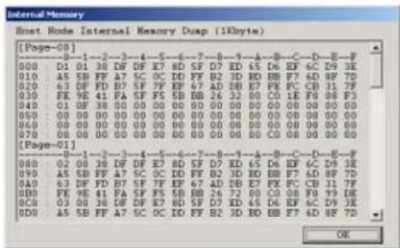
2.12 Dumping the Memory Contents of the PCM-2074
Returning to the Main Window of the CircLink™ EVB Software, in Figure 2.1, clicking "Memory" on the menu bar at the top of the window causes the PCM-2074 Host Node to dump its memory contents. The display format depends on the Page Size chosen (64 or 128 bytes). Both formats are illustrated below.
Memory Dump Format for PageSize=64

text_image
Internal Memory Host Node Internal Memory Dusp (1Kbyte) [Page-00] 000 D1 01 38 DF DF X7 BD SF D7 KD 65 DL RF 4C DN 3E 010 A5 SB FF A7 SC OC DD PF B2 3D ED BB F7 6D RF 7D 020 63 DF FD B7 SF 7F EF 67 AD DB E7 PE PC CB 31.7F 030 PE 9E 41 FA SF F6 5B BB 26 32 00 CO 1E F0 08 F3 [Page-01] 040 01 DF 38 DF 4E 5 6E-7 00 00 00 00 00 00 00 00 00 050 00 DF 38 DF 4E 5 6E-7 00 00 00 00 00 00 00 00 060 00 DF 38 DF 4E 5 6E-7 00 00 00 00 00 00 00 00 070 00 DF 38 DF 4E 5 6E-7 00 00 00 00 00 00 00 [Page-02] 080 02 DF 38 DF DF X7 BD SF D7 KD 65 DL RF 4C DN 3E 090 A5 SB FF A7 SC OC DD PF B2 3D ED BB F7 6D RF 7D 100 A5 DF FD B7 SF 7F EF 67 AD DB E7 PE PC CB 31.7F 110 PE 9E 41 FA SF F6 5B BB 26 72 00 CO 00 F0 DN DE OKMemory Dump Format for PageSize=128
text_image
Internal Memory Host: Node Internal Memory Dump (1kbyte) [Page-00] 00 0 1 2 3 4 5 6 7 8 9 10 11 12 13 14 15 16 17 18 19 20 010 01 01 38 48 DF E7 BD SF D7 ED 65 D6 EF 6C D9 3E 010 05 SB FF A7 SC OC ID PF B2 3D ED BB F7 6D EF 7D 020 63 DF FD B7 SF 7F EF 67 AD EB E7 PE FC CB 31 7F 030 FE 9E 41 PA SF F5 SB B8 26 32 00 C0 1E F0 08 P3 040 01 OF 38 00 00 00 00 00 00 00 00 00 00 00 050 00 00 00 00 00 00 00 00 00 00 00 00 00 060 00 00 00 00 00 00 00 00 00 00 00 00 00 070 00 00 00 00 00 00 00 00 00 00 C0 1E F1 F2 F3 [Page-01] 888 82 88 DEF EF E7 ED SF D7 ED 65 D6 EF 6C D9 E2 999 AE SD FF A7 SC OC ID PF B2 3D ED BB F7 6D EF 7D AAD 63 DF FD B7 SF 7F EF 67 AD EB E7 PE FC CB1 7F AOD FE SE AF PA SF F5 SB B8 26 72 00 C0 EF F9 D9 E2 OCD 83 DEF EF A7 ED BD SF D7 ED 65 D6 EF EC D9 D3 ODD A5 SB FF A7 SC OC ID PF B2 3D ED BB F7 ED F2 HD OKFigure 2.17 Memory Dump Formats
Each page in the memory dump shows the configuration information for the corresponding IO node. The information is a snapshot made when the memory dump window is opened; the information is not updated. The vertical scroll bar can be used to scroll through all the pages.
3 Error Messages
If errors are detected at start-up or during run-time, appropriate error messages will be displayed by the software. There are three types of errors that can be displayed:
■ System Errors - show errors returned by the Windows O/S.
■ Communication Errors - Detected when packets are being transmitted or received
■ Operation Errors - Detected during operation of the CircLink ™ EVB Software.
3.1 System Error Messages
These messages are displayed when a Windows system function that is called by the CircLink™ EVB Software detects an error. System functions that are used include open/close functions and I/O request calls to the device drivers. The message indicates the type of error and asks whether the software should quit or continue. The example show below occurs when there is an error opening the device driver. In this particular case, click "Yes" (close) and confirm that the device driver has been correctly installed before re-invoking the CircLink™ EVB Software.

text_image
ECTest Error Message Function: EcOpen() Code = -1 Do you want to exit? Yes NoFigure 3.1 System Error Message
3.2 Communication Error Messages
These kinds of errors cause a message like the one below to be displayed. Common causes of communication errors include:
■ Mismatch in settings between the Host Node and one or more IO Nodes
■ Attempting to communicate with a non-existent node.

text_image
I/O Node Settings Error Message Function: EclloNodeInit0 Code = -1 OK
text_image
I/O Node Settings: Error Message Function: Get Setting Info. EcSendCommand0 Code = -1 OKFigure 3.2 Typical Communication Error Message
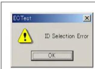
3.3 Operation Error Messages
Common causes of these kinds of errors are choosing invalid or incompatible configuration settings. the figure below shows two typical examples. In the first case, choose a different node ID. In the second case, change the Flag settings.
text_image
EOTest ID Selection Error OK
text_image
Select Error Can not select this item OKFigure 3.3 Typical Operation Error Messages
4 Device Driver Installation
This chapter describes how to install the PCM-2074 device driver that is used by the CircLink™ EVB Software from CD-ROM.
4.1 Installing to Windows 2000
Follow this procedure:
- Install the PCM-2074 in an unused PCMCIA Type II Slot
- The dialog box shown in Figure 4.1 is displayed, showing that the hardware has been recognized.

text_image
Found New Hardware Network Controller Installing ...Figure 4.1 PCM-2074 Card Detected Window
The dialog box shown in Figure 4.2 is displayed. Click Next>.

text_image
Found New Hardware Wizard Welcome to the Found New Hardware Wizard This wizard helps you install a device driver for a hardware device. To continue, click Next. < Back Next > CancelFigure 4.2 Driver Installation Welcome Window
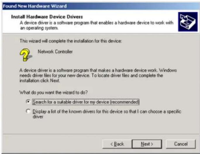
- The dialog box in Figure 4.3 is displayed, select "Search for a suitable driver for my device (recommended)" and click Next>.
text_image
Found New Hardware Wizard Install Hardware Device Drivers A device driver is a software program that enables a hardware device to work with an operating system. This wizard will complete the installation for this device: Network Controller A device driver is a software program that makes a hardware device work. Windows needs driver files for your new device. To locate driver files and complete the installation click Next. What do you want the wizard to do? • Search for a suitable driver for my device (recommended) • Display a list of the known drivers for this device so that I can choose a specific driver < Back Next > CancelFigure 4.3 Driver Installation Selection Window
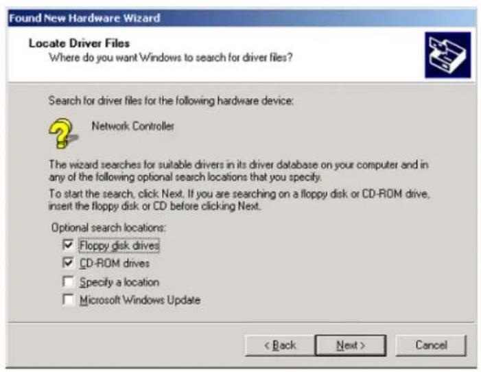
- Insert the CD containing the software in the CD-ROM driver, and in the dialog box shown in Figure 4.4, check "CD-ROM drives" and click Next>.
text_image
Found New Hardware Wizard Locate Driver Files Where do you want Windows to search for driver files? Search for driver files for the following hardware device: Network Controller The wizard searches for suitable drivers in its driver database on your computer and in any of the following optional search locations that you specify. To start the search, click Next. If you are searching on a floppy disk or CD-ROM drive, insert the floppy disk or CD before clicking Next. Optional search locations: ✓ Floppy disk drives ✓ CD-ROM drives □ Specify a location □ Microsoft Windows Update < Back Next > CancelFigure 4.4 Specifying which Drives to Look In
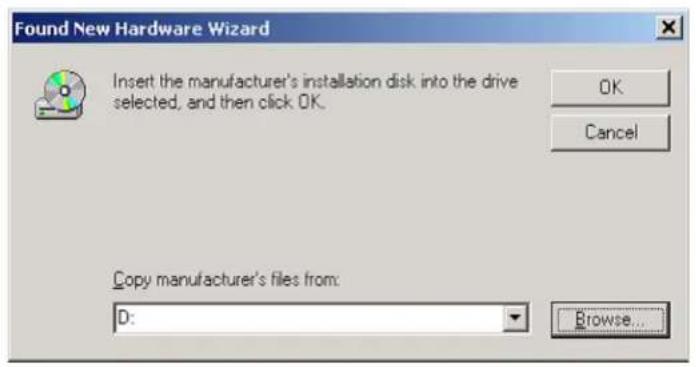
- In the dialog box in Figure 4.5, click "Browse".
text_image
Found New Hardware Wizard Insert the manufacturer's installation disk into the drive selected, and then click OK. OK Cancel Copy manufacturer's files from: D: Browse...Figure 4.5 Specifying which File to Open
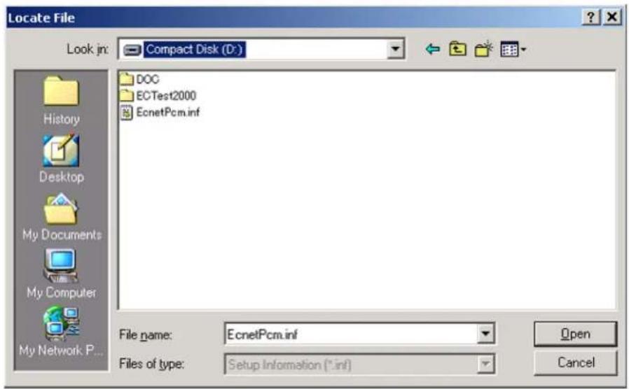
In the dialog box in Figure 4.6 select the "EcNetPCM.INF" file and click "Open."
text_image
Locate File Look in: Compact Disk (D:) History Desktop My Documents My Computer My Network P... DOC ECTest2000 EcnetPcm.inf File name: EcnetPcm.inf Files of type: Setup Information (*.inf) Open CancelFigure 4.6 Browsing for the File
- The dialog box in Figure 4.5 is now re-displayed. Click OK.
- The dialog box in Figure 4.7 is now displayed. Click Next>.

text_image
Found New Hardware Wizard Driver Files Search Results The wizard has finished searching for driver files for your hardware device. The wizard found a driver for the following device: SMSC CircLink(TMC2074) PCM-2074 PCMCIA Adapter Windows found a driver for this device. To install the driver Windows found, click Next. d:\ecnetpcm.inf < Back Next > CancelFigure 4.7 Confirming the Driver File
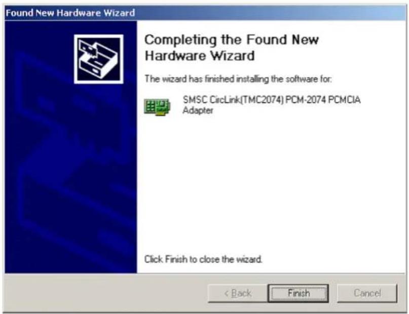
- The dialog box in Figure 4.8 is now displayed. Click Finish.

text_image
Found New Hardware Wizard Completing the Found New Hardware Wizard SMSC CircLink(TMC2074) PCM-2074 PCMCIA Adapter Windows has finished installing the software for this device. To close this wizard, click Finish.Figure 4.8 Installation Complete Window
4.1.1 Verifying Driver Installation
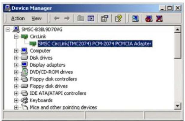
To verify that the driver has been installed, start Window's Device Manager, and confirm that the SMSC CircLink (TMC2074) PCM-2074 PCMCIA Adaptor is recognized as shown in Figure 4.9.
text_image
Device Manager Action View SMSC-B3BL9D70VG CircLink SMSC CircLink(TMC2074) PCM-2074 PCMCIA Adapter Computer Disk drives Display adapters DVD/CD-ROM drives Floppy disk controllers Floppy disk drives IDE ATA/ATAPI controllers Keyboards Mice and other pointing devicesFigure 4.9 Windows Device Driver Listing
To further confirm correct installation, double click "SMSC CircLink (TMC2074) PCM-2074 PCMCIA Adapter" to display the property dialog box as shown in Figure 4.10 below. Verify the status of the driver.

text_image
SMSC CircLink(TMC2074) PCM-2074 PCMCIA Adapter Properties General | Driver | Resources | SMSC CircLink(TMC2074) PCM-2074 PCMCIA Adapter Device type: CircLink Manufacturer: SMSC Japan Location: Texas Instruments ...... Device status This device is working properly. If you are having problems with this device, click Troubleshooter to start the troubleshooter. Troubleshooter... Device usage: Use this device (enable) OK CancelFigure 4.10 SMSC Driver Window
4.2 Installing to Windows XP
The installation procedure for Windows XP is as follows:
- Install the PCM-2074 to an unused Type II PCMCIA slot.
- The dialog box shown inFigure 4.11 is displayed. Click Next>.

text_image
Found New Hardware Wizard This wizard helps you install software for: Network Controller If your hardware came with an installation CD or floppy disk, insert it now. What do you want the wizard to do? • Install the software automatically (Recommended) • Install from a list or specific location (Advanced) Click Next to continue. < Back Next > CancelFigure 4.11 Installation Start-up Window
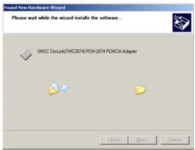
The system automatically searches for the device driver and displays the message shown in Figure 4.12.
text_image
Found New Hardware Wizard Please wait while the wizard installs the software... SMSC CircLink(TMC2074) PCM-2074 PCMCIA Adapter < Back Next > CancelFigure 4.12 System-search window
Once the driver installation is complete, the dialog shown in Figure 4.13 is displayed. Click Finish.
text_image
Found New Hardware Wizard Completing the Found New Hardware Wizard The wizard has finished installing the software for: SMSC CircLink(TMC2074) PCM-2074 PCMCIA Adapter Click Finish to close the wizard. < Back Finish CancelFigure 4.13 Installation Complete Window
Driver installation is now complete. To verify proper installation, refer to the steps listed in section 4.1.1.
5 References
Further information about the CircLink controllers, evaluation boards and related application notes can be found in the following documents. The latest versions are available from the SMSC website.
Table 5.1 CircLink Controllers
| PRODUCT DOCUMENT NAME TYPE | ||
| EVK-2074/84 | Instruction Manual for the EVK2074/84 Evaluation Board Kit | |
| PCM-2074 Instruction Manual for the PCM-2074 Evaluation Board pdf | ||
| EVB-2084 | Instruction Manual for the EVB-2084 Evaluation Board | |
| TMC2074 Datasheet for the TMC2074 CircLink Controller pdf | ||
| TMC2084 Datasheet for the TMC2084 CircLink Controller pdf | ||
| CircLinkTM EVB Software | Operation Manual (this document) pdf | |

SMSC™
80 ARKAY DRIVE, HAUPPAUGE, NY 11788 (631) 435-6000, FAX (631) 273-3123
Copyright © 2006 SMSC or Its subsidiaries. All rights reserved.
Circuit diagrams and other information relating to SMSC products are included as a means of illustrating typical applications. Consequently, complete information sufficient for construction purposes is not necessarily given. Although the information has been checked and is believed to be accurate, no responsibility is assumed for inaccuracies. SMSC reserves the right to make changes to specifications and product descriptions at any time without notice. Contact your local SMSC sales office to obtain the latest specifications before placing your product order. The provision of this Information does not convey to the purchaser of the described semiconductor devices any licenses under any patent rights or other intellectual property rights of SMSC or others. All sales are expressly conditional on your agreement to the terms and conditions of the most recently dated version of SMSC's standard Terms of Sale Agreement dated before the date of your order (the "Terms of Sale Agreement"). The product may contain design defects or errors known as anomalies which may cause the product's functions to deviate from published specifications. Anomaly sheets are available upon request. SMSC products are not designed, intended, authorized or warranted for use in any life support or other application where product failure could cause or contribute to personal injury or severe property damage. Any and all such uses without prior written approval of an Officer of SMSC and further testing and/or modification will be fully at the risk of the customer. Copies of this document or other SMSC literature, as well as the Terms of Sale Agreement, may be obtained by visiting SMSC's website at http://www.smsc.com. SMSC is a registered trademark of Standard Microsystems Corporation ("SMSC"). Product names and company names are the trademarks of their respective holders.
SMSC DISCLAIMS AND EXCLUDES ANY AND ALL WARRANTIES, INCLUDING WITHOUT LIMITATION ANY AND ALL IMPLIED WARRANTIES OF MERCHANTABILITY, FITNESS FOR A PARTICULAR PURPOSE, TITLE, AND AGAINST INFRINGEMENT AND THE LIKE, AND ANY AND ALL WARRANTIES ARISING FROM ANY COURSE OF DEALING OR USAGE OF TRADE. IN NO EVENT SHALL SMSC BE LIABLE FOR ANY DIRECT, INCIDENTAL, INDIRECT, SPECIAL, PUNITIVE, OR CONSEQUENTIAL DAMAGES; OR FOR LOST DATA, PROFITS, SAVINGS OR REVENUES OF ANY KIND; REGARDLESS OF THE FORM OF ACTION, WHETHER BASED ON CONTRACT; TORT; NEGLIGENCE OF SMSC OR OTHERS; STRICT LIABILITY; BREACH OF WARRANTY; OR OTHERWISE; WHETHER OR NOT ANY REMEDY OF BUYER IS HELD TO HAVE FAILED OF ITS ESSENTIAL PURPOSE, AND WHETHER OR NOT SMSC HAS BEEN ADVISED OF THE POSSIBILITY OF SUCH DAMAGES.