RN42 - Electronic component Microchip - Free user manual and instructions
Find the device manual for free RN42 Microchip in PDF.

User questions about RN42 Microchip
0 question about this device. Answer the ones you know or ask your own.
Ask a new question about this device
Download the instructions for your Electronic component in PDF format for free! Find your manual RN42 - Microchip and take your electronic device back in hand. On this page are published all the documents necessary for the use of your device. RN42 by Microchip.
USER MANUAL RN42 Microchip
RN41/42 Evaluation Kit
User's Guide
Note the following details of the code protection feature on Microchip devices:
• Microchip products meet the specification contained in their particular Microchip Data Sheet.
- Microchip believes that its family of products is one of the most secure families of its kind on the market today, when used in the intended manner and under normal conditions.
- There are dishonest and possibly illegal methods used to breach the code protection feature. All of these methods, to our knowledge, require using the Microchip products in a manner outside the operating specifications contained in Microchip's Data Sheets. Most likely, the person doing so is engaged in theft of intellectual property.
- Microchip is willing to work with the customer who is concerned about the integrity of their code.
- Neither Microchip nor any other semiconductor manufacturer can guarantee the security of their code. Code protection does not mean that we are guaranteeing the product as “unbreakable.”
Code protection is constantly evolving. We at Microchip are committed to continuously improving the code protection features of our products. Attempts to break Microchip's code protection feature may be a violation of the Digital Millennium Copyright Act. If such acts allow unauthorized access to your software or other copyrighted work, you may have a right to sue for relief under that Act.
Information contained in this publication regarding device applications and the like is provided only for your convenience and may be superseded by updates. It is your responsibility to ensure that your application meets with your specifications. MICROCHIP MAKES NO REPRESENTATIONS OR WARRANTIES OF ANY KIND WHETHER EXPRESS OR IMPLIED, WRITTEN OR ORAL, STATUTORY OR OTHERWISE, RELATED TO THE INFORMATION, INCLUDING BUT NOT LIMITED TO ITS CONDITION, QUALITY, PERFORMANCE, MERCHANTABILITY OR FITNESS FOR PURPOSE. Microchip disclaims all liability arising from this information and its use. Use of Microchip devices in life support and/or safety applications is entirely at the buyer's risk, and the buyer agrees to defend, indemnify and hold harmless Microchip from any and all damages, claims, suits, or expenses resulting from such use. No licenses are conveyed, implicitly or otherwise, under any Microchip intellectual property rights.
QUALITY MANAGEMENT SYSTEM
CERTIFIED BY DNV
=ISO/TS 16949=
Trademarks
The Microchip name and logo, the Microchip logo, dsPIC, FlashFlex, flexPWR, JukeBlox, KEELOQ, KEELOQ logo, Kleer, LANCheck, MediaLB, MOST, MOST logo, MPLAB, OptoLyzer, PIC, PICSTART, PIC ^32 logo, RightTouch, SpyNIC, SST, SST Logo, SuperFlash and UNI/O are registered trademarks of Microchip Technology Incorporated in the U.S.A. and other countries.
The Embedded Control Solutions Company and mTouch are registered trademarks of Microchip Technology Incorporated in the U.S.A.
Analog-for-the-Digital Age, BodyCom, chipKIT, chipKIT logo, CodeGuard, dsPICDEM, dsPICDEM.net, ECAN, In-Circuit Serial Programming, ICSP, Inter-Chip Connectivity, KleerNet, KleerNet logo, MiWi, MPASM, MPF, MPLAB Certified logo, MPLIB, MPLINK, MultiTRAK, NetDetach, Omniscient Code Generation, PICDEM, PICDEM.net, PICkit, PICtail, RightTouch logo, REAL ICE, SQI, Serial Quad I/O, Total Endurance, TSHARC, USBCheck, VariSense, ViewSpan, WiperLock, Wireless DNA, and ZENA are trademarks of Microchip Technology Incorporated in the U.S.A. and other countries.
SQTP is a service mark of Microchip Technology Incorporated in the U.S.A.
Silicon Storage Technology is a registered trademark of Microchip Technology Inc. in other countries.
GestlC is a registered trademarks of Microchip Technology Germany II GmbH & Co. KG, a subsidiary of Microchip Technology Inc., in other countries.
All other trademarks mentioned herein are property of their respective companies.
© 2014, Microchip Technology Incorporated, Printed in the U.S.A., All Rights Reserved.
ISBN: 978-1-63276-811-7
Microchip received ISO/TS-16949:2009 certification for its worldwide headquarters, design and wafer fabrication facilities in Chandler and Tempe, Arizona; Gresham, Oregon and design centers in California and India. The Company's quality system processes and procedures are for its PIC® MCUs and dsPIC® DSCs, KEELOO® code hopping devices, Serial EEPROMs, microperipherals, nonvolatile memory and analog products. In addition, Microchip's quality system for the design and manufacture of development systems is ISO 9001:2000 certified.
Object of Declaration: RN41/42 Evaluation Kit
EU Declaration of Conformity
Manufacturer:
Microchip Technology Inc.
2355 W. Chandler Blvd.
Chandler, Arizona, 85224-6199
USA
This declaration of conformity is issued by the manufacturer.
The development/evaluation tool is designed to be used for research and development in a laboratory environment. This development/evaluation tool is not a Finished Appliance, nor is it intended for incorporation into Finished Appliances that are made commercially available as single functional units to end users under EU EMC Directive 2004/108/EC and as supported by the European Commission's Guide for the EMC Directive 2004/108/EC (8 ^th February 2010).
This development/evaluation tool complies with EU RoHS2 Directive 2011/65/EU.
This development/evaluation tool, when incorporating wireless and radio-telecom functionality, is in compliance with the essential requirement and other relevant provisions of the R&TTE Directive 1999/5/EC and the FCC rules as stated in the declaration of conformity provided in the module datasheet and the module product page available at www.microchip.com.
For information regarding the exclusive, limited warranties applicable to Microchip products, please see Microchip's standard terms and conditions of sale, which are printed on our sales documentation and available at www.microchip.com.
Signed for and on behalf of Microchip Technology Inc. at Chandler, Arizona, USA

text_image
Derek Carlson VP Development Tools
NOTES:
Table of Contents
Preface 7
Chapter 1. Overview
1.1 Introduction ...... 13
1.2 RN41/42 Evaluation Kit Features 13
1.3 RN41/42 Evaluation Kit Contents and Part Details 14
1.4 RN41/42 Evaluation Kits/Board Contents 16
1.5 RN41/42 Evaluation Kit Related Information Contents 18
Chapter 2. Getting Started
2.1 Introduction ...... 19
2.2 Hardware Requirements ...... 19
2.3 Using the Evaluation Kit 20
2.4 Command Mode vs. Data Mode 21
2.5 Configure the Module Locally Using the USB Port 22
2.6 Enter Command Mode 22
2.7 Operating Modes ...... 23
2.8 Configuration Switches 24
2.9 Making a Bluetooth Connection 25
2.10 Security Modes 32
Chapter 3. Application Design Concerns
3.1 Introduction ...... 33
3.2 Concerns Related to RN41/42 33
Appendix A. RN41 and RN42 Evaluation Kit Schematics
A.1 Introduction 35
A.2 RN41 and RN42 Evaluation Kit Schematic 35
A.3 RN41 and RN42 Evaluation Kit PCB Layout and Assembly Drawings ..... 38
A.4 RN41 and RN42 Evaluation Kit Bill of Materials 40
A.5 RN41 and RN42 Evaluation Kit Physical Dimensions 41
Worldwide Sales and Service 43
NOTES:
Preface
NOTICE TO CUSTOMERS
All documentation becomes dated, and this manual is no exception. Microchip tools and documentation are constantly evolving to meet customer needs, so some actual dialogs and/or tool descriptions may differ from those in this document. Please refer to our web site (www.microchip.com) to obtain the latest documentation available.
Documents are identified with a "DS" number. This number is located on the bottom of each page, in front of the page number. The numbering convention for the DS number is "DSXXXXXA", where "XXXXX" is the document number and "A" is the revision level of the document.
For the most up-to-date information on development tools, see the MPLAB ^® IDE on-line help. Select the Help menu, and then Topics to open a list of available on-line help files.
INTRODUCTION
This chapter contains general information that will be useful to know before using the Product Name. Items discussed in this chapter include:
- Document Layout
• Conventions Used in this Guide - Warranty Registration
• Recommended Reading
• The Microchip Web Site
• Development Systems Customer Change Notification Service - Customer Support
• Document Revision History
DOCUMENT LAYOUT
This user's guide describes how to use the RN-41-EK and RN-42-EK Evaluation Boards. The document is organized as follows:
- Chapter 1. “Overview” – This chapter describes the hardware and software setup for RN41 and RN42 Evaluation Kits.
- Chapter 2. “Getting Started” – This chapter describes the RN41 and RN42 Evaluation Kit board as an independent development board for exploring the ASCII command set and prototyping of embedded systems.
- Chapter 3. “Application Design Concerns” – This chapter describes the application design concerns of the RN41 and RN42 modules.
- Appendix A. “RN41 and RN42 Evaluation Kit Schematics” – This appendix includes a schematic of the RN-41-EK and RN42-EK Evaluation Boards, PCB layout and the Bill of Materials.
CONVENTIONS USED IN THIS GUIDE
This manual uses the following documentation conventions:
DOCUMENTATION CONVENTIONS
| Description Represents Examples | ||
| Arial font: | ||
| Italic characters Referenced books | mPLAB | ^ IDE User's Guide |
| Emphasized text ...is the only compiler... | ||
| Initial caps A window the Output | window | |
| A dialog the Settings dialog | ||
| A menu selection select Enable Programmer | ||
| Quotes A field name in a window or dialog | "Save project before build" | |
| Underlined, italic text with right angle bracket | A menu path File>Save | —— |
| Bold characters A dialog button | Click OK | |
| A tab | Click the Power tab | |
| N'Rnnnn | A number in verilog format, where N is the total number of digits, R is the radix and n is a digit | 4'b0010, 2'hF1 |
| Text in angle brackets <> | A key on the keyboard | Press,, |
| Courier New font: | ||
| Plain Courier New | Sample source code | #define START |
| Filenames | autoexec.bat | |
| File paths | c:\mcc18\h | |
| Keywords | _asm, _endasm, static | |
| Command-line options | -Opa+, -Opa- | |
| Bit values | 0, 1 | |
| Constants | 0xFF, 'A' | |
| Italic Courier New | A variable argument | file.o, where file can be any valid filename |
| Square brackets [] | Optional arguments | mccl8 [options] file [options] |
| Curly brackets and pipe character: { | } | Choice of mutually exclusive arguments; an OR selection | errorlevel {0|1} |
| Ellipses... Replaces repeated text | var_name [, | var_name...] |
| Represents code supplied by user | void main (void) { ... } | |
WARRANTY REGISTRATION
Please complete the enclosed Warranty Registration Card and mail it promptly. Sending in the Warranty Registration Card entitles users to receive new product updates. Interim software releases are available at the Microchip web site.
RECOMMENDED READING
This user's guide describes how to use the RN-41-EK and RN42-EK Evaluation Boards. Other useful documents are listed below. The following Microchip documents are available and recommended as supplemental reference resources:
RN41 Module Data Sheet
RN42 Module Data Sheet
PICDEM™ PIC18 Explorer Demonstration Board User's Guide (DS51721)
Explorer 16 Development Board User's Guide (DS51589)
Bluetooth Data Module Command Reference and Advanced Information User's Guide
Microchip provides online support via our web site at http://www.microchip.com. This web site is used as a means to make files and information easily available to customers. Accessible by using your favorite Internet browser, the web site contains the following information:
- Product Support – Data sheets and errata, application notes and sample programs, design resources, user's guides and hardware support documents, latest software releases and archived software
- General Technical Support – Frequently Asked Questions (FAQs), technical support requests, online discussion groups, Microchip consultant program member listing
- Business of Microchip – Product selector and ordering guides, latest Microchip press releases, listing of seminars and events, listings of Microchip sales offices, distributors and factory representatives
DEVELOPMENT SYSTEMS CUSTOMER CHANGE NOTIFICATION SERVICE
Microchip's customer notification service helps keep customers current on Microchip products. Subscribers will receive e-mail notification whenever there are changes, updates, revisions or errata related to a specified product family or development tool of interest.
To register, access the Microchip web site at http://www.microchip.com, click on Customer Change Notification and follow the registration instructions.
The Development Systems product group categories are:
- Compilers – The latest information on Microchip C compilers and other language tools. These include the MPLAB® C compiler; MPASM™ and MPLAB 16-bit assemblers; MPLINK™ and MPLAB 16-bit object linkers; and MPLIB™ and MPLAB 16-bit object librarians.
- Emulators – The latest information on the Microchip MPLAB REAL ICE™ in-circuit emulator.
- In-Circuit Debuggers – The latest information on the Microchip in-circuit debugger, MPLAB ICD 3.
- MPLAB IDE – The latest information on Microchip MPLAB IDE, the Windows® Integrated Development Environment for development systems tools. This list is focused on the MPLAB IDE, MPLAB SIM simulator, MPLAB IDE Project Manager and general editing and debugging features.
- Programmers – The latest information on Microchip programmers. These include the MPLAB PM3 device programmer and the PICkit™ 3 development programmers.
CUSTOMER SUPPORT
Users of Microchip products can receive assistance through several channels:
• Distributor or Representative
- Local Sales Office
• Field Application Engineer (FAE)
- Technical Support
Customers should contact their distributor, representative or Field Application Engineer (FAE) for support. Local sales offices are also available to help customers. A listing of sales offices and locations is included in the back of this document.
Technical support is available through the web site at: http://support.microchip.com
DOCUMENT REVISION HISTORY
Revision A (November 2014)
This is the initial released version of this document.
NOTES:
Chapter 1. Overview
1.1 INTRODUCTION
This user's guide describes the hardware and software setup for RN41 and RN42 Evaluation Kits. The RN41 and RN42 evaluation boards are field-ready with Bluetooth® SIG qualified platforms based on RN41 and RN42 modules, respectively. The boards have the flexibility to connect directly to computer/laptops via a standard USB interface (via the FTDI chipset), or to embedded controllers through the TTL UART interface. The status LEDs, DIP switches and Signal headers/connectors enable integration into existing systems. The user can configure and control the modules from a console using simple ASCII command language. Once the configuration is setup, the module can connect over Bluetooth.
The evaluation kit configures the Bluetooth module using the command interface, create connections, and transfer data. The RN-41-EK and RN-42-EK evaluation boards support the Serial Port Profile (SPP) and Human Interface Device (HID) profiles. In this user's guide, the SPP profile is used for the instructions. For more information on the profiles and how to switch between these profiles, refer to the Bluetooth Data Module Command Reference and Advanced Information User's Guide.
For data sheet and other details related to RN41 and RN42 modules, refer to the Microchip web site at http://www.microchip.com.
This chapter discusses the following topics:
• RN41/42 Evaluation Kit Features
• RN41/42 Evaluation Kit Contents and Part Details
• RN41/42 Evaluation Kits/Board Contents
• RN41/42 Evaluation Kit Related Information Contents
1.2 RN41/42 EVALUATION KIT FEATURES
1.2.1 RN41 Evaluation Board Features
The RN41 Evaluation Board has the following features:
- Supports fully qualified Bluetooth version 2.1 module, supports version 2.1 + Enhanced Data Rate (EDR)
- UART (SPP or HCI) and USB (only HCI) data connection interfaces
- Sustained SPP data rates: 240 Kbps (slave), 300 Kbps (master)
• HCI data rates: 1.5 Mbps sustained, 3.0 Mbps burst in HCI mode - Embedded Bluetooth stack profiles included (requires no host stack): GAP, SDP, RFCOMM, and L2CAP protocols, with SPP and DUN profile support
- Supports Class 1 high-power amplifier with on-board ceramic RF chip antenna (RN41) or without antenna (RN41N)
- Supports 2 LEDs, 4 DIP switches for Configuration, SPI pads for firmware programmings
- Postage-stamp sized form factor of 44 mm x 24 mm x 13 mm.
1.2.2 RN42 Evaluation Board Features
The RN42 Evaluation Board has the following features:
- Supports fully qualified Bluetooth version 2.1 module, supports version 2.1
- UART (SPP or HCI) and USB (only HCI) data connection interfaces
- Sustained SPP data rates: 240 Kbps (slave), 300 Kbps (master)
• HCI data rates: 1.5 Mbps sustained, 3.0 Mbps burst in HCI mode - Embedded Bluetooth stack profiles included (requires no host stack): GAP, SDP, RFCOMM, and L2CAP protocols, with SPP and DUN profile support
- Supports 2 LEDs, 4 DIP switches for Configuration, SPI pads for firmware programmings
- Postage-stamp sized form factor of 44 mm x 24 mm x 13 mm.
1.3 RN41/42 EVALUATION KIT CONTENTS AND PART DETAILS
The evaluation kit includes the hardware required to connect the evaluation board to the host computer, see Table 1-1. To evaluate the module on the evaluation board, the user needs a computer with a USB port running the Microsoft Windows or Mac OS-X operating system.
Note: Prior to the evaluation, install the FTDI drivers for the USB cable. If the drivers are not automatically installed, download and install the FTDI drivers from http://ww1.microchip.com/downloads/en/DeviceDoc/FTDI-Drivers.zip.
Depending on the development kit ordered, the package contains one of the following development boards:
- RN-41-EK or RN-42-EK Board - Contains the RN41 (Class 1)/RN42 (Class 2) Bluetooth module.
- USB cable - Connects user's computer to the evaluation board.
Table 1-1 lists the part number of RN-41/42-EK Evaluation Kit.
TABLE 1-1: RN41/42 EVALUATION KIT PART DETAILS
| Description | Part |
| RN41 Evaluation board RN-41-EK | |
| RN42 Evaluation board RN-42-EK |
Number
Figure 1-1 and Figure 1-2 show the evaluation kit contents and part number information.
FIGURE 1-1: RN41 EVALUATION KIT CONTENTS

text_image
RN-41 ROUING MICROCHIP FC CE RoHS RN-41-EK RN41 Evaluation BoardFIGURE 1-2: RN42 EVALUATION KIT CONTENTS

text_image
RN-42 00066646D22AFLY477 MAC NO: T9J-RN42 FCC ID: T9J-RN42 IC: 6514A-RN42 QDID B014876 RoHS CE RN-42-EK RN42 Evaluation Board1.4 RN41/42 EVALUATION KITS/BOARD CONTENTS
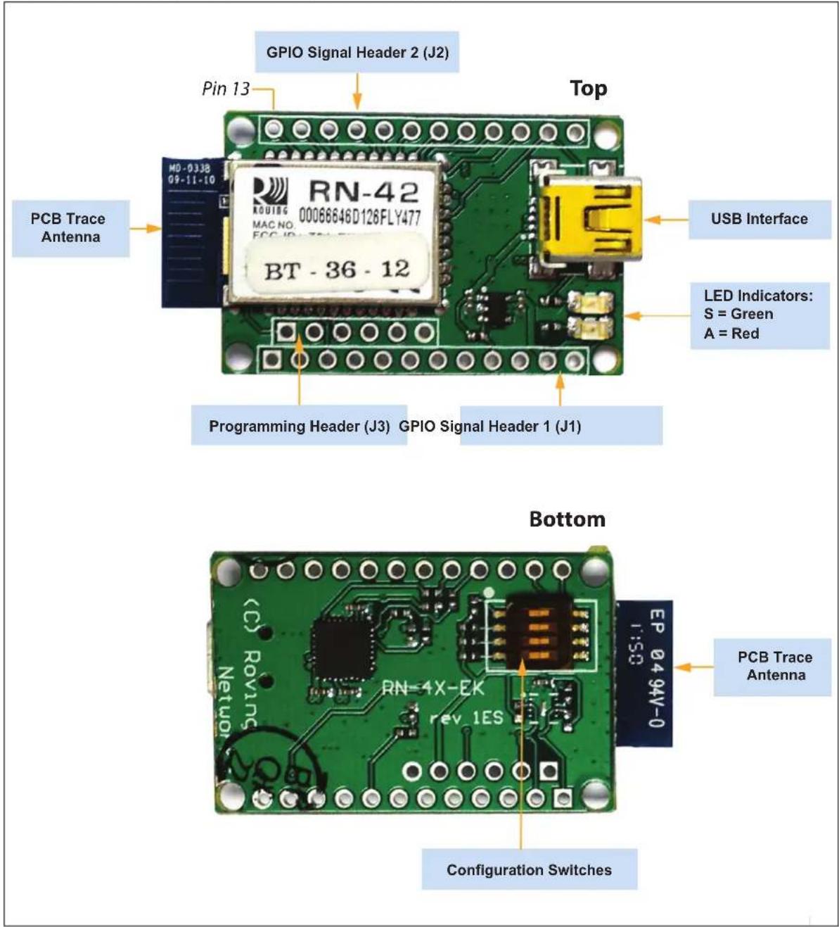
The components of the RN41/42 Evaluation Board are shown in Figure 1-3. This figure describes the evaluation board's interfaces and connectors. Table 1-2 describes the status LEDs. The Green LED indicates the status of the Bluetooth connection and the device in Configuration mode. The RN41 and RN42 modules are pin compatible and the description applies to both RN-41-EK and RN-42-EK boards. For the board's schematic, refer to Appendix A. "RN41 and RN42 Evaluation Kit Schematics".
FIGURE 1-3: RN-41-EK & RN-42-EK EVALUATION BOARD
text_image
GPIO Signal Header 2 (J2) Pin 13 Top USB Interface PCB Trace Antenna RN-42 00066646D126FLY477 BT - 36 - 12 LED Indicators: S = Green A = Red Programming Header (J3) GPIO Signal Header 1 (J1) Bottom PCB Trace Antenna EP 04 94V-0 RN-4X-EK rev 1ES Configuration SwitchesNote: Figure 1-3 shows the RN-42-EK board. This figure is similar to RN-41-EK board.
GPIO Signal Header 1 (J1) GPIO Signal Header 2 (J2) Programming Header (J3)
Configuration Switches
| Switch | Description |
| romatic Master | |
| 4 Default Baud Rate | |
TABLE 1-2: STATUS LEDS
| Mode | Green LED (S) | Red LED (A) |
| Fast blink, 10 times per second | Command mode | — |
| Blinks twice per second | Boot up, remotely configurable | — |
| Blinks once per second | Discoverable/idle | Data over the UART |
| Solid on | Connected | — |
TABLE 1-3: RN41/42 EVALUATION KIT HARDWARE
| Hardware | Description | RN-41-EK | RN-42-EK |
| Evaluation board | Contains the Bluetooth® module and connectors | For RN41 Module | For RN42 Module |
| Power-Up | Interface for powering up the evaluation boards | USB | USB |
| LEDs | To indicate Status and for Debugging | Available | Available |
| Switches | Used to access/configure functions in RN41/42 module such as factory default, Connection mode, and so on | Available | Available |
| 10-Pin Sensor Interface | Analog sensor interface supported provides direct connections to read the temperature, acceleration, and analog data | Available | Available |
| Communication Interface | UART and USB | Available | Available |
| USB Connector On-board | Provides power to the evaluation board and supports communication (COM Port) | Available | Available |
1.5 RN41/42 EVALUATION KIT RELATED INFORMATION CONTENTS
To obtain the sample application codes, see details from the Bluetooth User Manual using the following links:
• http://www.microchip.com/RN-41-EK
- http://www.microchip.com/RN-42-EK.
Note: All the factory-shipped RN modules are available with firmware version and profile details. For more information, refer to "Bluetooth Data Module Command Reference and Advanced Information User's Guide" available at http://www.microchip.com.
Chapter 2. Getting Started
2.1 INTRODUCTION
This chapter describes the RN41/42 Evaluation Kit board as an independent development board for exploring the ASCII command set and prototyping of embedded systems. Certain hardware and software/utilities are essential to support the development of demo applications. This chapter discusses the following topics:
• Hardware Requirements
- Software/Utility Requirements
- Module Configuration
2.2 HARDWARE REQUIREMENTS
Along with RN-41-EK or RN-42-EK boards, an USB cable is connected (virtual COM port) to evaluate hardware setup and to run the firmware/demo applications.
2.2.1 Hardware Setup
To setup the RN41/42 Evaluation Board demo, perform the following steps:
- Connect the USB cable to a USB port on the host system (computer/laptop) and to the USB connector on the evaluation board.
- Power to RN-41/42-EK evaluation board is only obtained through the host computer/laptop.
Note: If the drivers are not automatically installed, download and install the FTDI drivers from http://ww1.microchip.com/downloads/en/DeviceDoc/FTDI-Drivers.zip.
- Once the FTDI drivers are installed, the COM port is automatically assigned based on the active connection.
- Note the COM port to which the USB cable is connected.
Figure 2-1 shows the setup arrangement of RN41/RN42 Evaluation Boards connected to a computer/laptop.
FIGURE 2-1: COMPLETE HARDWARE SETUP

natural_image
Laptop with network cable and USB port connected to a Lenovo laptop (no visible text or symbols on the device)2.3 USING THE EVALUATION KIT
Program Bluetooth devices over the Bluetooth link or through the serial interface (USB port) using a simple ASCII command language, which is similar to the industry standard Hayes AT protocol. The set command configures the Bluetooth module and get commands echoes the current configuration. Configuration settings modified with the set command do not take effect until the module has been rebooted, even though the get command may show otherwise. To configure the Bluetooth devices, a Bluetooth enabled PC (either built-in or using a USB Bluetooth dongle) is required. Only one device can be configured at a time. Once configured, device settings are saved (independent of power-down) until users explicitly change settings or the factory defaults are restored.
Note: For detailed information on the ASCII commands used to configure the Bluetooth module, refer to the Bluetooth Data Module Command Reference and Advanced Information User's Guide.
2.4 COMMAND MODE VS. DATA MODE
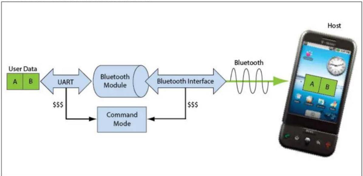
The Bluetooth device operates in two modes: Data mode (default) and Command mode. Upon power-up, the device is in Data mode. While in Data mode, the module is essentially a data pipe. When the module receives data from a remote Bluetooth device over a serial port profile (SPP) connection, it strips the Bluetooth headers and trailers and passes the user data to the UART. When data is written to the UART, the module constructs the Bluetooth packet and sends it over the Bluetooth SPP connection. Thus, the entire process of sending/receiving data to the host is transparent to the end microprocessor. Figure 2-2 illustrates the Bluetooth communication pipe.
FIGURE 2-2: DATA & COMMAND MODES
flowchart
graph LR
    A["User Data A B"] -->|UART $$$$| B["Bluetooth Module"]
    B -->|Bluetooth Interface $$$$| C["Bluetooth"]
    C --> D["Host"]
    E["Command Mode"] --> B
The default configuration for the Bluetooth device are as follows:
- Bluetooth Slave mode
- Keyboard Default Authentication mode (no pin code required)
- Serial port 115,200 Kbps baud rate, 8 bits, no parity, 1 stop bit
- Serial port flow control disabled
- Low-power mode off.
The device is configurable if set into Command mode and ASCII commands are sent over a serial port or the Bluetooth link. Once the configuration parameters are changed, parameter values persist until it is changed or perform a factory reset.
Note: User can only configure the Bluetooth module in two ways: locally using host computer's USB port and via Bluetooth.
Terminal emulator application/program on PC is required to complete the setup.
Note: Depending on the operating system, the users can opt to use either the TeraTerm (Windows OS) or CoolTerm (Mac OS-X) terminal emulator programs.
2.5 CONFIGURE THE MODULE LOCALLY USING THE USB PORT
Setup the RN-41-EK or RN-42-EK hardware as described in Section 2.2.1 "Hardware Setup". With the Bluetooth device connected and powered on, run a terminal emulator and open the COM port to which the cable is connected. Configure the virtual COM port connected to the RN-41-EK or RN-42-EK as shown in Table 2-1.
Command mode can be switched through the UART interface via the USB connector at any time or during certain conditions when the device does not have a Bluetooth connection. If the device is in Configuration mode and gets connected, the device exits Configuration mode and data passes back and forth from the remote device.
Note: If the device is in Auto-Connect Master Mode, user cannot enter the Command mode when connected over Bluetooth. For more information on the various Operating modes, see Section 2.7 "Operating Modes".
2.6 ENTER COMMAND MODE
To enter Command mode, launch a terminal emulator from the PC and specify the module's default serial port settings. See Table 2-1.
TABLE 2-1: SERIAL PORT SETTINGS
| Setting | Value |
| Port COM port to which you attached the module | |
| Baud rate 115200 | |
| Data rate 8 bits | |
| Patiry None | |
| Stop bits 1 | |
| Flow control | None |
Type \\\\ (sequentially without any delays between \$ characters) into the terminal emulator to enter Command mode. The module returns the string CMD, which indicates that the connection and terminal settings are correct. While in Command mode, the device accepts ASCII bytes as commands.
When the module is powered up and no command is entered within a 60-second configuration window, the module goes into fast Data mode and all characters are ignored including \\\\. When user enters a valid command, the module returns AOK. It returns ERR for an invalid command and ? for unrecognized commands. Type h
A quick check to confirm that the user is in Command mode, type the X
FIGURE 2-3: VIEW CURRENT SETTINGS

text_image
CMD Ver 6.30beta 08/26/2014 (c) Microchip Technology ***Settings*** BTA=0006666AB872 BTName=RNBT-B872 Baudrt(SW4)=115K Mode =Slav Authen=1 PinCod=1234 Bonded=0 Rem=NONE SET ***ADVANCED Settings*** SrvName= RNI-SPP SrvClass=0000 DevClass=1F00 InqWindw=0100 PagWindw=0100 CfgTimer=255 StatuStr=NULL HidFlags=200 DIRtimer=8 KeySwapr=0 ***OTHER Settings*** Profile= SPP CfgChar= $ SniffEna=0 LowPower=0 TX Power=0 IOPorts= 0 IOValues=0 Sleeptmr=0 DebugMod=0 RoleSwch=02.7 OPERATING MODES
The Bluetooth device has several Operating modes, which user can set using the SM command in Command mode.
Note: In all Master modes, the device cannot be discovered or configured remotely over Bluetooth.
2.7.1 Slave Mode (SM, 0)
This is the default mode, in which other Bluetooth devices can discover and connect to the device. Outbound connections can also be performed in this mode.
2.7.2 Master Mode (SM, 1)
In this low-speed connection mode, the device makes a connection when a connect command (c) is received. This command can also contain the Bluetooth address of the remote device. If a device is not specified, the module uses the stored remote address. The connection can be broken if the special break character or string is sent. To set the break character, use the so command. This mode is useful when user needs the device to initiate connections (not to receive them). In this mode, the device is not discoverable or connectable.
2.7.3 Trigger Mode (SM, 2)
In this low-speed connection mode, the device automatically connects when a character is received on the serial port (UART). The connection continues as long as characters are received on either end. The device has a configurable timeout (user can set using the ST command) that disconnects the module after the specified number of seconds of inactivity (1 to 255), or a configurable break character is received.
2.7.4 Auto-Connect Master Mode (SM, 3)
In this mode, the device automatically reconnects to the stored address on power-up when the connection is lost. This mode can be set by command, or by setting the external DIP switch 3 during power-up. If an address is not stored and DIP switch 2 is set, the device performs an inquiry process and the first device found that matches the Class Of Device (COD) is stored. In this mode, high-speed data is passed without being interpreted which means the connection cannot be broken through commands or software break characters. If a disconnect occurs, the device attempts to reconnect until successful.
2.7.5 Auto-Connect DTR Mode (SM, 4)
This mode must be set by command. It operates like Auto-Connect Master Mode, except that user has to control the connection and disconnection with DIP switch 3. Turning the DIP switch on initiates the auto-connect process, while turning the DIP switch off causes a disconnect.
2.7.6 Auto-Connect ANY Mode (SM, 5)
This mode must be set by command. This mode operates like Auto-Connect DTR Mode, except that each time the DIP switch is set, an inquiry is performed and the first device found is connected. The stored address is not used, and the address found is never stored.
2.7.7 Pairing Mode (SM, 6)
In this mode, the device attempts to connect with the remote device that matches the stored remote address. To set the remote address, use the SR command.
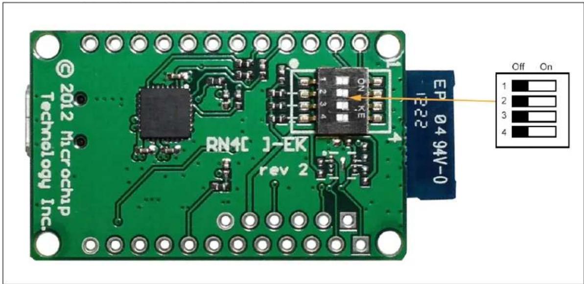
2.8 CONFIGURATION SWITCHES
The evaluation boards have small configuration switches at the bottom. These can be configured or flipped using a paper clip or a small screwdriver. Holding the board with the PCB antenna facing to the right, the switch numbering and on/off positions are shown in Figure 2-4.
FIGURE 2-4: CONFIGURATION SWITCHES
text_image
© 2012 Microchip Technology Inc. RN4C 1-EK rev 2 EP 0494V-0 Off On 1 2 3 4Table 2-2 describes the functions controlled by the switches.
TABLE 2-2: CONFIGURATION SWITCH FUNCTIONS
| Switch | Function Default (Off) | Description | |
| 1 | Restore factory defaults | Do not restore factory defaults. | Turn on the switch, power-up the evaluation kit, and toggle the switch three times to return the module to its factory settings. The Green LED (labeled as S) blinks quickly for a moment and then continues to blink about once per second. |
| 2 | Automatic discovery Automatic | discovery is turned off. | In Slave mode, if DIP switch 2 is set and DIP switch 3 is not set, it results in a special class of device that the master uses to auto-connect. If switch 3 also turned on, the module performs a search, stores, and connects to a remote RN41/42 Bluetooth device. |
| 3 | Automatic master | Automatic master is turned off. | With this switch turned on, the module acts as Bluetooth master and auto-connects to a stored remote address. You must first set the Bluetooth address of the slave device using the SR command or using instant cable replacement settings. If DIP switch 2/GPIO3 is also set, a new discovery/pairing can be made. |
| 4 | Default baud rate With this switch | switch turned off, the default 115200 baud rate is overridden by software baud rate configuration commands. | If this switch is turned on, the baud rate is 9600 and the module ignores the software configuration. |
2.9 MAKING A BLUETOOTH CONNECTION
As a default, the Bluetooth module acts as a slave and the PC is the master. Connect to the Bluetooth module using the host computer's Bluetooth device manager, which varies depending on the operating system. Regardless of the operating system, it follows the same process: Discovery, Pairing, and Connecting.
2.9.1 Discovery
When user turns on the RN-41-EK or RN-42-EK, the Green LED (labeled as S) blinks once per second and the module is discoverable. Open the host PC's Bluetooth device manager and choose to "Add a device". The Bluetooth device manager's icon is located at the bottom right corner on the host's computer screen in the taskbar for Windows, and at the upper right corner for Mac OS-X. The Bluetooth device manager displays a list of discoverable Bluetooth devices. Figure 2-5 illustrates the discovery of Bluetooth devices on host computer.
FIGURE 2-5: DISCOVERY - ADD A BLUETOOTH ^® DEVICE

text_image
Devices and Printers ▶ Bluetooth Devices Search Devices and Printers Add a device Add a printer Devices (1) RNBT-B872 1 item2.9.2 Pairing
To pair with the evaluation board, double click the board's name in the list. The firmware automatically stores up to 8 pairings from remote hosts using the First-In, First-Out (FIFO) method. The evaluation board's Default Authentication mode is the SSP keyboard mode (no pin required). However, most PCs require authentication and display a pin code. If a user uses a Bluetooth USB dongle (e.g., RN-USB-T), host PC prompts the user to choose how the pairing must be done. Figure 2-6 shows examples of pairing with and without a pin code.
Note: If host PC displays a pin code, user must select the YES button to confirm if correct.
FIGURE 2-6: PAIRING - COMPARING PIN CODES AND PAIRING OPTIONS

text_image
Add a device Compare pairing codes between your computer and this device This will verify that you are connecting to the correct device. 154705 Does the code above match the code on the device: Yes No The device is not displaying a code RNBT-B872 What if this code does not match the code on my device? Next Cancel
text_image
Add a device Select a pairing option → Create a pairing code for me The device has a keypad. → Enter the device's pairing code The device comes with a pairing code. Check for one on the device or in the device manual. → Pair without using a code This type of device, such as a mouse, does not require a secure connection. How can I tell if my device has a pairing code? Next CancelWhen the Bluetooth device manager completes pairing, it issues a message that the Bluetooth device is installed on COMX where COMX is unique to the used host computer. In some cases, the Bluetooth device manager creates two COM ports; in this case, only use the COM port labeled as outgoing. Figure 2-7 shows an example of COM port settings.
FIGURE 2-7: PAIRING - BLUETOOTH
® COM PORT SETTINGS

text_image
Bluetooth Settings Options COM Ports Hardware Share PIM Interface This computer is using the COM (serial) ports listed below. To determine whether you need a COM port, read the documentation that came with your Bluetooth device. Port Direction Name COM21 Outgoing RNBT-B872 'RNI-SPP' COM24 Incoming RNBT-B872 Add... Remove Choose a COM port for a Bluetooth enabled device. OK Cancel ApplyIf the remote Bluetooth device does not require authentication, a connection can occur without the pairing process. However, the Bluetooth specification requires that if either device involved in the pairing process requires authentication, the other device must participate to ensure a secure link. The RN41/RN42 modules default to an Open mode, such that the module does not require authentication. For more information on using pass keys, see Section 2.10 "Security Modes". The module may use simple pairing (SSP) if it attempts to pair with devices that support the Bluetooth specification version 2.1 + EDR. SSP does not require the user to remember the pin code, but it asks to confirm the 6-digit number if the device has a display capability.
2.9.3 Connecting
In most cases, the user connects from another device to the RN-41-EK or RN-42-EK as an outgoing Bluetooth connection. User can also make an incoming connection in which the evaluation board initiates the connection to the remote device.
2.9.3.1 OUTGOING CONNECTIONS
To establish an outgoing Bluetooth connection from a PC to the RN-41-EK or RN-42-EK board, open the module's outgoing COM port from host application or a terminal emulator. When the user establish a connection by opening the COM port, the evaluation board's Green LED (labeled as S) goes on solid (not blinking) to indicate that the device is connected. The device remains connected until user closes the COM port, remove power from the board, or terminate the connection using the K, 1 command. Refer to the Bluetooth Data Module Command Reference and Advanced Information User's Guide for more information on using commands.
Once connected, the device is in Data mode enabling data to flow in both directions. The board's Red LED (labeled as A) blinks once per second when data is transferred over the UART. For configuration and programming, the device must be in Command mode. For more information, see Section 2.6 "Enter Command Mode".
Note: Only one client can connect to a slave device at a time. As a master, the device can make multiple connections, but only in a point-to-point, serialized fashion. The RN41 and RN42 modules do not currently support multi-point Master mode.
2.9.3.2 INCOMING CONNECTIONS
For an incoming connection, use the port specified in host Bluetooth settings as incoming (refer to Figure 2-7). The PC of host listens for an incoming connection from the remote Bluetooth device, in this case the RN-41-EK or RN-42-EK.
To make an incoming connection, perform the following steps:
- User needs the MAC address of the PC's Bluetooth radio to connect from the RN-41-EK or RN-42-EK to the host PC. Open the PC's Bluetooth advanced settings to find the MAC address. Figure 2-8 shows the Bluetooth Radio MAC addresses that are connected to the PC.
- Pair evaluation board with the PC, see Section 2.9.2 "Pairing".
- Open a terminal (for example, terminal A) and connect it to the evaluation board's outgoing COM port. Run this terminal on the host PC or another computer.
- Open a second terminal (for example, terminal B) on the host PC to listen for the incoming Bluetooth connection using the incoming COM port number.
- Type c,
in terminal A to establish an SPP connection to the host PC. See Figure 2-9 for an example connection. -
Try the following commands:
-
\\\$ to enter Command mode
- SO, % to enable status message to see connect/disconnect conditions
- R, 1 to reboot
- \\\$ to re-enter Command mode
-
- to enable local echo
-
C,
to attempt a connection with a remote device. Characters user Type in terminal B are sent over Bluetooth to the host PC and display in terminal A. Any characters entered in terminal A are transmitted to terminal B. -
To kill the connection, type the K,1
command in terminal B.
2.9.3.3 CONNECTING TWO RN-41-EK OR RN-42-EK BOARDS
Open the COM ports assigned to the two modules. As a default, the modules are in Slave mode when powered up. The two slaves can be connected to each other or one of the modules reconfigured to be a master, can connect to a slave.
To make a connection between two RN-41-EK (Module A and Module B) or between two RN-42-EK (Module A and Module B) boards, perform the following steps:
- Enter the Command mode in both the modules by executing \$ command in the corresponding terminals.
- Execute GB command in the terminal of module B to get its Bluetooth MAC address. Module A will require this address.
- Set the Authentication mode in both the modules by using SA,
command.
Note: The Authentication mode must be the same in both modules.
- Type c,
in terminal A to establish an SPP connection from Module A to Module B. - Try the following commands in both the terminals:
- \\\$ to enter Command mode
- SO, % to enable status message to see connect/disconnect conditions
- R, 1 to reboot
- \\\$ to re-enter Command mode
- + to enable local echo
- C,
- To kill the connection, type the K, 1
command in terminal B or terminal A.
FIGURE 2-8: PC'S BLUETOOTH
® RADIO MAC ADDRESS

text_image
Device Manager File Action View Help Batteries Bluetooth Radios Microsoft Bluetooth Enumerator ThinkPad Bluetooth 2.1 with Enhanced Data Rate II Computer Disk drives Display adapters DVD/CD-ROM drives Human Interface Devices IDE ATA/ATAPI controllers IEEE 1394 Bus host controllers Intel® Centrino® Wireless Bluetooth® 3.0 + High Speed Devices Keyboards Mice and other pointing devices Modems Monitors Network adapters Ports (COM & LPT) Intel(R) Active Management Technology - SOL (COM3) Standard Serial over Bluetooth link (COM10) Standard Serial over Bluetooth link (COM11) Standard Serial over Bluetooth link (COM5) Standard Serial over Bluetooth link (COM6) Standard Serial over Bluetooth link (COM7) Standard Serial over Bluetooth link (COM8) USB Serial Port (COM9)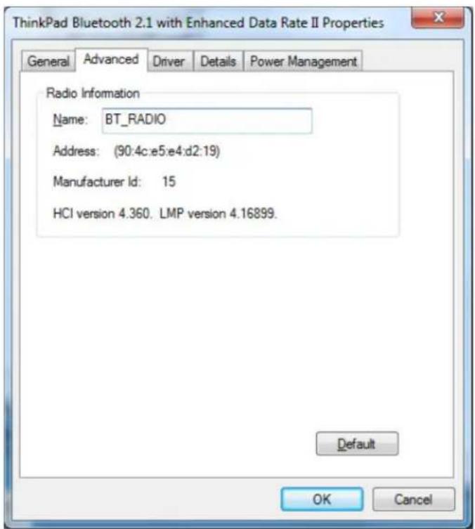
text_image
ThinkPad Bluetooth 2.1 with Enhanced Data Rate II Properties General Advanced Driver Details Power Management Radio Information Name: BT_RADIO Address: (90:4c:e5:e4:d2:19) Manufacturer Id: 15 HCI version 4.360. LMP version 4.16899. Default OK CancelFIGURE 2-9: TERMINALS A AND B
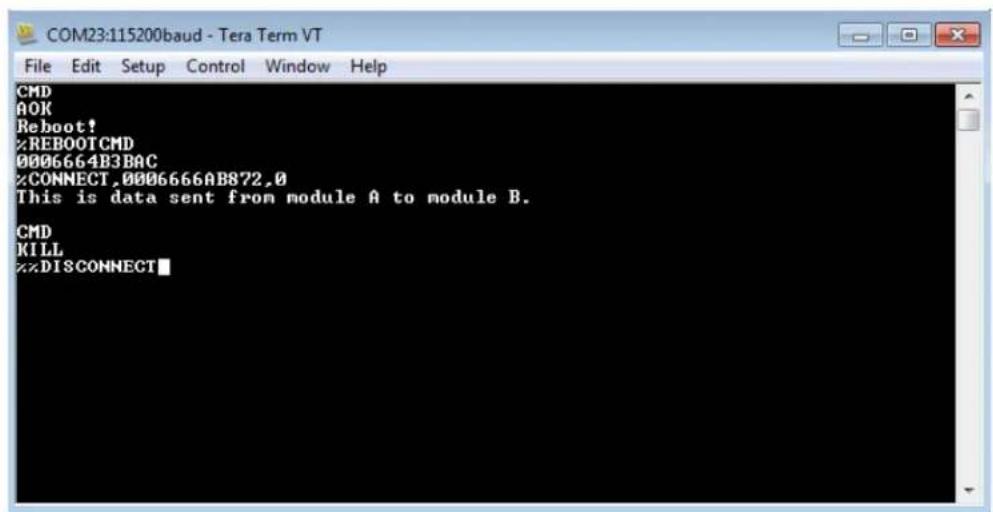
text_image
COM23:115200baud - Tera Term VT File Edit Setup Control Window Help CMD AOK Reboot! %REBOOTCMD 0006664B3BAC %CONNECT,0006666AB872,0 This is data sent from module A to module B. CMD KILL %DISCONNECT
text_image
COM20:115200baud - Tera Term VT File Edit Setup Control Window Help CMD AOK Reboot! %REBOOTCMD TRYING %CONNECT,0006664B3BAC,0 This is data sent from module B to module A.%DISCONNECT2.10 SECURITY MODES
The Bluetooth module supports authentication. If the local or remote Bluetooth device has authentication enabled, a pin code is required the first time a connection is attempted. The pin code is a series of numbers or characters from 1 to 16 characters in length. After the user enters the pin code, the Bluetooth devices compare these codes. If a match is found, a link key is generated and stored. Usually, but not always, the remote device stores the link key. For subsequent connections, the devices compare link keys. If correct, the user must not re-enter the pin code. If the remote device is a PC or PDA, the user generally is prompted to enter this pin code. To remove the stored link key on the remote device, the user typically needs to "unpair" or remove the device from the Bluetooth manager. User can change the pin code to remove the link key on the Bluetooth module, forcing a new pin code exchange to occur upon subsequent connection attempts.
Note: Only one master can connect to the Bluetooth module at a time.
Chapter 3. Application Design Concerns
3.1 INTRODUCTION
The following sections provide information on designing with the RN41 and RN42 modules, including radio interference, factory reset, solder reflow profile, connection status, and so on.
3.2 CONCERNS RELATED TO RN41/42
3.2.1 Reset Circuit
The RN41 contains a 1k pull-up to VCC, and the reset polarity is active-low. The module's reset pin has an optional power on-reset circuit with a delay, which must be only required if the input power supply has a very slow ramp or tends to bounce or have instability on power-up. Often a microcontroller or embedded CPU I/O is available to generate the reset once power is stable. If not, the designers can use one of the many low-cost power supervisor chips currently available, such as the MCP809 and MCP102/121.
3.2.2 Factory Reset Using GPIO4
It is recommended that the designers connect the GPIO4 pin to a switch, jumper, or resistor so it can be accessed. This pin can be used to reset the module to its factory default settings, which is critical in situations where the module has been not properly configured. To reset the module to the factory defaults, GPIO4 must be high on power-up and then toggle the switch in an ON-OFF-ON-OFF-ON sequence with one second interval between the transitions.
3.2.3 Connection Status
GPIO5 is available to drive an LED, and it blinks at various speeds to indicate status, see Table 3-1. GPIO2 is an output that directly reflects the connection state as shown in Table3-2.
TABLE 3-1: GPIO5 STATUS
| GPIO5 Status Description |
| Toggle at 1 Hz The module is discoverable and waiting for a connection. |
| Toggle at 10 Hz The module is in Command mode. |
| High The module is connected to another device over Bluetooth. |
TABLE 3-2: GPIO2 STATUS
| GPIO2 Status Description | |
| High The module is connected to another device over Bluetooth. | |
| Low | The module is not connected over Bluetooth. |
3.2.4 HCI Mode
RN41/42 module offers the Host Controller Interface (HCI) mode in addition to the standard operational mode of its Bluetooth modules (standard mode refers to the on-board stack running on the module). In HCI mode, the on-board stack is bypassed and the module is put in a state that runs the Bluetooth baseband. The HCI provides a command reference interface to the baseband controller and the link manager, and provides access to the hardware status and control registers. This interface provides a uniform method for accessing the Bluetooth baseband capabilities.
In this mode, The Bluetooth stack is no longer on-board the module. It is offloaded to the interfacing host processor. The Bluetooth module is used as a radio, performing the lower level MAC functionalities, while the application stack runs on the host processor. Using the module in HCI mode enables designers to implement profiles that are not natively supported on the Bluetooth module.
Note: HCI mode requires a separate firmware build that must be loaded into the module's flash at the factory. It is not upgradeable in the field.
RN41 module offers HCI mode in two hardware interfaces:
• HCI over UART (RN41/42HCI-I/RM)
• HCI over USB (RN41/42U-I/RM)
3.2.4.1 HCI OVER UART
In this mode, UART is the hardware interface between the host processor and the Bluetooth module. User must interface the flow control signals between the host processor and the Bluetooth module for the HCI interface to work. Failure to do so can cause the host processor and the Bluetooth module to become out of sync and break the Bluetooth link.
3.2.4.2 HCI OVER USB
In this mode, USB is the hardware interface between the host processor and the Bluetooth module. In this architecture, the Bluetooth module is the USB slave and the host processor is the USB host. Using the USB interface offers the advantage of a faster data link between the Bluetooth module and the host processor. With this architecture, it is possible to achieve Bluetooth's theoretical maximum throughput of 3 Mbps.
3.2.5 Using the SPI Bus to Upgrade the Flash Memory
While not required, this bus is very useful for configuring the Bluetooth module's advanced parameters. The bus is required when upgrading the module's firmware. In typical application schematic a 6-pin header can be implemented to gain access to this bus. A minimum-mode version might simply use the SPI signals (4 pins) and obtain ground and VCC from elsewhere in the design.
3.2.6 Minimizing Radio Interference
When laying out the carrier board for the RN41 module, the areas under the antenna and shielding connections must not have surface traces, ground planes, or exposed vias. For optimal radio performance, the RN41 module's antenna end must protude at least 5 mm beyond any metal enclosure.
3.2.7 Low Power
For RN42, to achieve low-power operation, hold the module's RESET pin low. With RESET = 0 VDC, the module consumes 35 uA of power. If RESEST is left floating or high, the module consumes 3 mA in Sleep mode. To obtain the lowest power, the RN42 must be passive (in Slave mode and not trying to make connections).
Appendix A. RN41 and RN42 Evaluation Kit Schematics
A.1 INTRODUCTION
This appendix provides the RN41 and RN42 Evaluation Boards schematic, PCB layout and Bill of Materials (BOM).
• RN41 and RN42 Evaluation Kit Schematic
• RN41 and RN42 Evaluation Kit PCB Layout and Assembly Drawings
• RN41 and RN42 Evaluation Kit Bill of Materials
• RN41 and RN42 Evaluation Kit Physical Dimensions
A.2 RN41 AND RN42 EVALUATION KIT SCHEMATIC
Figure A-1 and Figure A-2 show the Evaluation Boards schematic.
FIGURE A-1: RN41 EVALUATION BOARD SCHEMATIC

text_image
M1 RNV41 Module SPI_MOSI GND SPI_MOSI PI O6 PI O6 PI O7 PI O7 RESET N RESET SPI_SCK SPI_SCK PCM_CLK PCM_CLK PCM_SYNC PCM_IN PCM_IN PCM_OUT 3.3V 12 11 10 9 8 7 6 5 4 3 2 1 0 AIO1 GND PIO11 PIO10 PIO9 PIO8 PIO8 UART_CTS UART_RTS UART_TX UART_RX AIO0 SHIELD AIO1 GND PIO11 PIO10 PIO9 PIO8 UART_CTS UART_RTS UART_TX UART_RX AIO0 AIO1 GND PIO11 PIO10 PIO9 PIO8 UART_CTS UART_RTS UART_TX UART_RX AIO0 SI3 24 SPI_MISO SO SPI_C5A SPI_S5 SPI_O4 SPI_O5 SPI_O3 SPI_O2 SPI_O2 USB_D- USB_D+ USB_D+ USB_D+ USB_D+ CTS5 CTS5 TXD RXD U1 TC11B5 VOUT VI N BYP SHDN 3 SHDN R1 3k3 C1 1uF C2 1uF VBUS 5 VOUT U1 TC11B5 VOUT VI N 3 SHDN R1 3k3 C1 1uF C4 100nF C6 100nF C5 100nF HEADER 1 PI O6 PI O7 RESET_N V82 SHDN 3.3V V82 V82 V82 V82 V82 V82 V82 V82 V82 V82 V82 V82 V82 V82 V82 V82 V82 V82 V82 V82 V82 V82 V82 V82 V82 V82 V82 V82 V82 V82 V82 V82 V82 V82FIGURE A-2: RN42 EVALUATION BOARD SCHEMATIC

text_image
M1 RN-42 Module SPI_MOSI GND SPI_MOSI PI06 PI06 PI07 PI07 RESET N RESET SPI_SCK SPI_SCK PCM_CLK PCM_CLK PCM_SYNC PCM_IN PCM_OUT 3.3V 11 12 3.3V 12 A101 A10T A10GND A10P11 A10P10 A10P09 A10P08 A10R A10D UART_CTS UART_RTS UART_TX UART_RX UART_RX A100 SHIELD A10T A10GND A10P11 A10P10 A10P09 A10P08 A10R A10D 3.3V VBUS C2 1uF U1 TC1185 VOUT BYP 3 GND 5HDN 3 SHDN R1 3k3 C1 1uF C6 100nF C5 100nF VCCIO 3V3OUT U3 FT232RQ TXD RXD RTS CTS DTR DSR DCD RF RESET CBUSO CBUS1 CBUS2 CBUS3 CBUS4 OSCI OSCD 20 GND 17 GND 4 GND KGN D THPAD 24 33 26 28 29 30 31 32 33 34 35 36 37 38 39 40 41 42 43 44 45 46 47 48 49 50 51 52 53 54 55 56 57 58 59 60 61 62 63 64 65 66 67 68 69 70 71 72 73 74 75 76 77 78 79 80 81 82 83 84 85 86 87 88 89 90 91 92 93 94 95 96 97 98 99 100 VCCIO VCC XTD R13 3k3R12 RXD RTS CTS DTR DSR DCD RF CBUSO CT BusD P USDBM USBDP USBUS J4 VBUS D- DI GND USB Mini B MTAB 3.3V PI O6 PI O7 RESET_N V82 SHDN J1 V82 V82 V82 V82 V82 V82 V82 V82 V82 V82 V82 V82 V82 V82 V82 V82 V82 V82 V82 V82 V82 V82 V82 V82 V82 V82 V82 V82 V82 V82 V82 V82 V82 V82 UVB1 R18 R15 A101 R17 R16 J3 SPI_MISO SPI_MOSI SPI_SCR SPI_SS SPI MASTERA.3 RN41 AND RN42 EVALUATION KIT PCB LAYOUT AND ASSEMBLY DRAWINGS
The RN41/42 Evaluation Board is a 2-layer, FR4, 0.062 inch, plated through a hole PCB construction. Figure A-3 through Figure A-6 show the PCB constructions and Assembly Drawings.
FIGURE A-3: RN41/RN42 EVALUATION BOARD TOP SILKSCREEN

text_image
Intel 3-EK SATS Microport © SATS MicroportFIGURE A-5: RN41/RN42 EVALUATION BOARD TOP COPPER

natural_image
Red printed circuit board with various traces and components, no visible text or symbolsFIGURE A-6: RN41/42 EVALUATION BOARD BOTTOM COPPER

natural_image
Blue printed circuit board with integrated circuits and traces, no visible text or symbolsA.4 RN41 AND RN42 EVALUATION KIT BILL OF MATERIALS
TABLE A-1: RN41 EVALUATION BOARD BILL OF MATERIALS (BOM)
| Reference Value Description | Vendor Vendor P/N | |||
| C1, C2 1 uF Cap ceramic, 10%, 16V, X5R, 0402 TDK Corporation C1005X5R1C105K | ||||
| C4, C5, C6 100 nF Cap ceramic, -20%, 80%, 16V, Y5V, 0402 Yageo | CC0402ZRY5V7BB104 | |||
| D1 Green LED | Clear, Green | LED, 10 mA, 2.1V, 569 nm, 130 degrees, 1206 | Lite-On Inc LTST-C1 | |
| D2 Red LED | Clear, Red LED, 10 mA, 1.8 V, 638 nm, 130 degrees, 1206 | Lite-On Inc LTST-C1 | ||
| J4 | USB Mini B CONN U | USB RCPT MINI B 5PS R/A SMD JAE | DX2R005HN2E700 | |
| M1 | RN-41 | RN41 Module | Microchip | RN41 |
| R1, R7, R8, R9, R10, R11, R12 | 3k3 | Res, 5%, 0.1 W, 0402 | Panasonic - ECG | ERJ-2GEJ332X |
| R2, R3 | 470 | Res, 5%, 0.1 W, 0402 | Panasonic - ECG | ERJ-2GEJ471X |
| R15, R18 | 300k | Res, 1%, 0.1 W, 0402 | Panasonic - ECG | ERJ-2RKF3003X |
| R16, R17 | 100k | Res, 1%, 0.1 W, 0402 | Panasonic - ECG | ERJ-2RKF1003X |
| S1 | 4 x DIP Switch | SWITCH DIP 4POS HALF PITCH SMD | C&K Components | TDA04H0SB1R |
| U1 | TC1185-3.3V | Linear Voltage Regulator | Microchip | TC1185-3.3VCT713 |
| U3 | FT232RQ | IC USB FS SERIAL UART 32-QFN | FTDI | FT232RQ-REEL |
TABLE A-2: RN42 EVALUATION BOARD BILL OF MATERIALS (BOM)
| Reference | Value | Description | Vendor | Vendor P/N |
| C1, C2 | 1 uF | Cap ceramic, 10%, 16V, X5R, 0402 | TDK Corporation | C1005X5R1C105K |
| C4, C5, C6 | 100 nF | Cap ceramic, -20%, 80%, 16V, Y5V, 0402 | Yageo | CC0402ZRY5V7BB104 |
| D1 Green LED Clear, Green LED, 10 | mA, 2.1V, 569 nm, 130 degrees, 1206 | Lite-On Inc | LTST-C150GKT | |
| D2 Red LED Clear, Red LED, 10 mA, 1.8 V, 638 nm, 130 degrees, 1206 | Lite-On Inc | LTST-C150CKT | ||
| J4 | USB Mini B | CONN USB RCPT MINI B 5PS R/A SMD | JAE | DX2R005HN2E700 |
| M1 | RN-42 | RN42 Module | Microchip | RN42 |
| R1, R7, R8, R9, R10, R11, R12 | 3k3 | Res, 5%, 0.1 W, 0402 | Panasonic - ECG | ERJ-2GEJ332X |
| R2, R3 | 470 | Res, 5%, 0.1 W, 0402 | Panasonic - ECG | ERJ-2GEJ471X |
| R15, R18 | 300k | Res, 1%, 0.1 W, 0402 | Panasonic - ECG | ERJ-2RKF3003X |
| R16, R17 | 100k | Res, 1%, 0.1 W, 0402 | Panasonic - ECG | ERJ-2RKF1003X |
| S1 | 4 x DIP Switch | SWITCH DIP 4POS HALF PITCH SMD | C&K Components | TDA04H0SB1R |
| U1 | TC1185-3.3V | Linear Voltage Regulator | Microchip | TC1185-3.3VCT713 |
| U3 | FT232RQ | IC USB FS SERIAL UART 32-QFN | FTDI | FT232RQ-REEL |
A.5 RN41 AND RN42 EVALUATION KIT PHYSICAL DIMENSIONS
Figure A-7 shows the physical dimensions of the RN41/42 Evaluation Board.
FIGURE A-7: RN41/42 PHYSICAL DIMENSIONS

text_image
39.284 (mm) M1 J4 Ω U1 Ω R3 D2 R1 R2 D1 24.4 (mm)NOTES:
Worldwide Sales and Service
AMERICAS
Corporate Office
2355 West Chandler Blvd.
Chandler, AZ 85224-6199
Tel: 480-792-7200
Fax: 480-792-7277
Technical Support:
http://www.microchip.com/
support
Web Address:
www.microchip.com
Atlanta
Duluth, GA
Tel: 678-957-9614
Fax: 678-957-1455
Austin, TX
Tel: 512-257-3370
Boston
Westborough, MA
Tel: 774-760-0087
Fax: 774-760-0088
Chicago
Itasca, IL
Tel: 630-285-0071
Fax: 630-285-0075
Cleveland
Independence, OH
Tel: 216-447-0464
Fax: 216-447-0643
Dallas
Addison, TX
Tel: 972-818-7423
Fax: 972-818-2924
Detroit
Novi, MI
Tel: 248-848-4000
Houston, TX
Tel: 281-894-5983
Indianapolis
Noblesville, IN
Tel: 317-773-8323
Fax: 317-773-5453
Los Angeles
Mission Viejo, CA
Tel: 949-462-9523
Fax: 949-462-9608
New York, NY
Tel: 631-435-6000
San Jose, CA
Tel: 408-735-9110
Canada - Toronto
Tel: 905-673-0699
Fax: 905-673-6509
ASIA/PACIFIC
Asia Pacific Office
Suites 3707-14, 37th Floor
Tower 6, The Gateway
Harbour City, Kowloon
Hong Kong
Tel: 852-2943-5100
Fax: 852-2401-3431
Australia - Sydney
Tel: 61-2-9868-6733
Fax: 61-2-9868-6755
China - Beijing
Tel: 86-10-8569-7000
Fax: 86-10-8528-2104
China - Chengdu
Tel: 86-28-8665-5511
Fax: 86-28-8665-7889
China - Chongqing
Tel: 86-23-8980-9588
Fax: 86-23-8980-9500
China - Hangzhou
Tel: 86-571-8792-8115
Fax: 86-571-8792-8116
China - Hong Kong SAR
Tel: 852-2943-5100
Fax: 852-2401-3431
China - Nanjing
Tel: 86-25-8473-2460
Fax: 86-25-8473-2470
China - Qingdao
Tel: 86-532-8502-7355
Fax: 86-532-8502-7205
China - Shanghai
Tel: 86-21-5407-5533
Fax: 86-21-5407-5066
China - Shenyang
Tel: 86-24-2334-2829
Fax: 86-24-2334-2393
China - Shenzhen
Tel: 86-755-8864-2200
Fax: 86-755-8203-1760
China - Wuhan
Tel: 86-27-5980-5300
Fax: 86-27-5980-5118
China - Xian
Tel: 86-29-8833-7252
Fax: 86-29-8833-7256
China - Xiamen
Tel: 86-592-2388138
Fax: 86-592-2388130
China - Zhuhai
Tel: 86-756-3210040
Fax: 86-756-3210049
ASIA/PACIFIC
India - Bangalore
Tel: 91-80-3090-4444
Fax: 91-80-3090-4123
India - New Delhi
Tel: 91-11-4160-8631
Fax: 91-11-4160-8632
India - Pune
Tel: 91-20-3019-1500
Japan - Osaka
Tel: 81-6-6152-7160
Fax: 81-6-6152-9310
Japan - Tokyo
Tel: 81-3-6880-3770
Fax: 81-3-6880-3771
Korea - Daegu
Tel: 82-53-744-4301
Fax: 82-53-744-4302
Korea - Seoul
Tel: 82-2-554-7200
Fax: 82-2-558-5932 or
82-2-558-5934
Malaysia - Kuala Lumpur
Tel: 60-3-6201-9857
Fax: 60-3-6201-9859
Malaysia - Penang
Tel: 60-4-227-8870
Fax: 60-4-227-4068
Philippines - Manila
Tel: 63-2-634-9065
Fax: 63-2-634-9069
Singapore
Tel: 65-6334-8870
Fax: 65-6334-8850
Taiwan - Hsin Chu
Tel: 886-3-5778-366
Fax: 886-3-5770-955
Taiwan - Kaohsiung
Tel: 886-7-213-7830
Taiwan - Taipei
Tel: 886-2-2508-8600
Fax: 886-2-2508-0102
Thailand - Bangkok
Tel: 66-2-694-1351
Fax: 66-2-694-1350
EUROPE
Austria - Wels
Tel: 43-7242-2244-39
Fax: 43-7242-2244-393
Denmark - Copenhagen
Tel: 45-4450-2828
Fax: 45-4485-2829
France - Paris
Tel: 33-1-69-53-63-20
Fax: 33-1-69-30-90-79
Germany - Dusseldorf
Tel: 49-2129-3766400
Germany - Munich
Tel: 49-89-627-144-0
Fax: 49-89-627-144-44
Germany - Pforzheim
Tel: 49-7231-424750
Italy - Milan
Tel: 39-0331-742611
Fax: 39-0331-466781
Italy - Venice
Tel: 39-049-7625286
Netherlands - Drunen
Tel: 31-416-690399
Fax: 31-416-690340
Poland - Warsaw
Tel: 48-22-3325737
Spain - Madrid
Tel: 34-91-708-08-90
Fax: 34-91-708-08-91
Sweden - Stockholm
Tel: 46-8-5090-4654
UK - Wokingham
Tel: 44-118-921-5800
Fax: 44-118-921-5820
03/25/14