PIC18F55K42 - Electronic component Microchip - Free user manual and instructions
Find the device manual for free PIC18F55K42 Microchip in PDF.

User questions about PIC18F55K42 Microchip
0 question about this device. Answer the ones you know or ask your own.
Ask a new question about this device
Download the instructions for your Electronic component in PDF format for free! Find your manual PIC18F55K42 - Microchip and take your electronic device back in hand. On this page are published all the documents necessary for the use of your device. PIC18F55K42 by Microchip.
USER MANUAL PIC18F55K42 Microchip
Interfacing the MikroElektronika Weather Click Board™ with the PIC18F25K42
Preface

Important: Notice to customers:
All documentation becomes dated, and this manual is no exception. Microchip tools and documentation are constantly evolving to meet customer needs, so some actual dialogs and/or tool descriptions may differ from those in this document. Please refer to our website (www.microchip.com) to obtain the latest documentation available.
Documents are identified with a "DS" number. This number is located on the bottom of each page, in front of the page number. The numbering convention for the DS number is "DSXXXXXA", where "XXXXX" is the document number and "A" is the revision level of the document.
For the most up-to-date information on development tools, see the MPLAB ^® IDE online help. Select the Help menu, and then Topics to open a list of available online help files.
Introduction
This document describes how to use the device as a development tool to emulate and debug firmware on a target board, as well as how to program devices.
The MikroElektronika Weather Click module contains the Bosch BME280 Environmental Sensor that is used to detect humidity, barometric pressure, and temperature. This user's guide explains how to connect the Weather Click to the PIC18F25K42 microcontroller, send and receive commands and raw weather data, and convert the data into a usable format.
Recommended Reading
For the latest information on using the device, read the "Readme for Device #.htm" file (an HTML file) in the Readmes subdirectory of the MPLAB ^® IDE installation directory. The release notes (Readme) contain update information and known issues that may not be included in this user's guide.
Hardware/Software Requirements
This demonstration uses the following hardware and software components:
Hardware:
• Curiosity High Pin Count (HPC) Development Board (DM164136)
• PIC18F25K42 Microcontroller (PIC18F25K42-I/SP)
- MikroElektronika Weather Click Board ^TM (MIKROE-1978)
• MCP2200 USB-to-UART Breakout Module (ADM00393) - USB Micro-B 5-pin cable (Curiosity to PC for programming/USB power)
- USB Mini-B 5-pin cable (MCP2200 to PC for displaying data)
- Jumper wires
Software:
- MPLABX ^ IDE v4.15 or higher
• XC8 Compiler v1.45 or higher
• Tera Term or equivalent PC terminal program
Other Relevant Documents:
- Bosch "BME280 Combined Humidity and Pressure Sensor" Data Sheet
- "PIC18(L)F24/25K42 28-Pin, Low-Power High-Performance Microcontrollers with XLP Technology" Data Sheet (DS40001869)
- TB3192, "Using the SPI module on 8-bit PIC ^ Microcontrollers" Technical Brief (90003192)
Table of Contents
Preface....1
Hardware/Software Requirements.... 1
- Application Overview....4
1.1. BME280 Environmental Sensor....4
- Application Configuration....9
2.1. Hardware Configuration....9
2.2. Software Configuration....11
- Conclusion....36
The Microchip Web Site....37
Customer Change Notification Service....37
Customer Support....37
Microchip Devices Code Protection Feature.... 37
Legal Notice....38
Trademarks.... 38
Quality Management System Certified by DNV....39
Worldwide Sales and Service....40
1. Application Overview
The demo uses a PIC18F25K42 microcontroller to communicate with the MikroElektronika Weather Click Board to read temperature, pressure, and humidity levels of the environment in which the demo is placed. Once the weather data has been acquired and processed, the information is transmitted to a PC terminal program for display.
1.1 BME280 Environmental Sensor
The Weather Click contains the Bosch BME280 Environmental Sensor. Communication with the sensor is handled either over the I²C or SPI interfaces. For this demo, the SPI interface is used; therefore, the jumper selector resistors must be changed from the default right position to the left position (see Figure 1-1). The Weather Click operates at 3.3V nominal, and routes power to the sensor's V DD and V DDIO pins.
The sensor features three operating modes: Sleep, Forced, and Normal modes. This application uses Forced mode as recommended by Bosch for weather monitoring since the temperature, humidity, and pressure readings will not rapidly change. Forced mode allows user software to decide when to read the sensor. Each time a measurement has completed, the sensor returns to Sleep mode, reducing power consumption.
Figure 1-1. Weather Click Jumper Locations
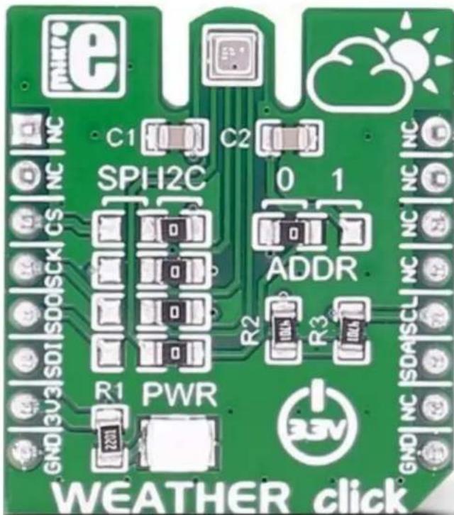
text_image
e NC C1 C2 SPH2C 0 1 CS ADDR R1 PWR R2 R3 GND | NC | SDA | SCL | NC | NC SDI | SDO | SCK | CS ADDR AGV WEATHER click1.1.1 Register Map
The BME280 contains several important registers, as shown in Figure 1-2.
Data Registers:
The 'hum_lsb' and 'hum_msb' registers are read-only and contain the 16-bit raw humidity measurement output data.
The ‘temp_xlsb’, ‘temp_lsb’, and ‘temp_msb’ registers are read-only and are combined to form the 20-bit raw temperature output data.
The 'press_xlsb', 'press_lsb', and 'press_msb' registers are read-only and are combined to form the 20-bit raw pressure output data.
Control Registers:
The 'config' register controls the rate, filter, and interface options of the sensor. The 't_sb<2:0>' bits determine the inactive standby time when operating in normal mode. The 'filter<2:0>' bits determine the time constant of the IIR filter. The 'spi3w_en' bit determines whether the SPI interface uses the standard four-wire interface or a three-wire interface.
The 'ctrl_meas' register controls the oversampling settings for temperature and pressure readings and the sensor's mode of operation. The 'osrs_t<2:0>' bits control oversampling of temperature data. The 'osrs_p<2:0>' bits control oversampling of pressure data. The 'mode<1:0>' bits determine which mode the sensor operates in: Sleep, Forced, or Normal. It is important to note that the 'ctrl_meas' register must be written to after changing settings in the 'ctrl_hum' register for the changes to become effective.
The ‘status’ register is read-only and is used to indicate the status of the sensor. The ‘measuring’ bit is set whenever a conversion is running and is clear when the conversion results have been transferred to the data registers. The ‘im_update’ bit is set when the Nonvolatile Memory (NVM) data is actively being copied into the calibration registers.
The 'ctrl_hum' register contains the 'osrs_h<2:0>' bits, which control the oversampling of humidity data. It is important to note that changes to the 'ctrl_hum' register only become effective after a write to the 'ctrl_meas' register.
The 'reset' register is used to perform a Power-on Reset (POR) procedure. Writing the value of 0xB6 will direct the sensor to perform a POR. Writing any other values will have no effect. This register is write-only; reads from this register will always result in 0x00.
The 'id' register contains the sensor's chip identification number, which is always a value of 0x60.
Calibration Registers:
Register ‘calib00’ through ‘calib31’ holds the sensor’s calibration values for humidity, temperature, and pressure readings. These registers have to be used to compensate for variations that occur due to the individual sensing elements of the sensor.
Figure 1-2. BME280 Register Map
| Register | Address | bit 7 bit 6 bit 5 bit 4 bit 3 bit 2 bit 1 bit 0 Reset Value | |||||||
| hum_lsb 0xFE 0x00 | hum<7:0> | ||||||||
| hum_msb 0xFD 0x80 | hum<15:8> | ||||||||
| temp_xlsb 0xFC 0 0 0 0 0x00 temp<3:0> | |||||||||
| temp_lsb 0xFB 0x00 | temp<11:4> | ||||||||
| temp_msb 0xFA 0x80 | temp<19:12> | ||||||||
| press_xlsb 0xF9 | press<3:0> | 0 0 0 0 0x00 | |||||||
| press_lsb 0xF8 | press<11:4> | 0x00 | |||||||
| press_msb 0xF7 | press<19:12> | 0x80 | |||||||
| config | 0xF5 | t_sb<2:0> | filter<2:0> | reserved | spi3w_en | 0x00 | |||
| ctrl_meas | 0xF4 | osrs_t<2:0> | osrs_p<2:0> | mode<1:0> | 0x00 | ||||
| status | 0xF3 | reserved | measuring | reserved | im_update | 0x00 | |||
| ctrl_hum | 0xF2 | reserved | osrs_h<2:0> | 0x00 | |||||
| calib31 0xE7 | dig_H6 | varies part-to-part | |||||||
| calib30 0xE6 | dig_H5<15:8> | ||||||||
| calib29 0xE5 | dig_H5<7:0> | ||||||||
| calib28 0xE4 | dig_H4<15:8> | ||||||||
| calib27 0xE3 | dig_H4<7:0> | ||||||||
| calib26 0xE2 | dig_H3<15:8> | ||||||||
| calib25 0xE1 | dig_H3<7:0> | ||||||||
| reset | 0xE0 0x00 | reset<7:0> | |||||||
| id | 0xD0 0x60 | chip_id<7:0> | |||||||
| calib24 0xA1 | dig_H1<7:0> | varies part-to-part | |||||||
| calib23 0x9F | dig_P9<15:8> | ||||||||
| calib22 0x9E | dig_P9<7:0> | ||||||||
| calib21 | 0x9D | dig_P8<15:8> | |||||||
| calib20 | 0x9C | dig_P8<7:0> | |||||||
| calib19 0x9B | dig_P7<15:8> | ||||||||
| calib18 0x9A | dig_P7<7:0> | ||||||||
| calib17 | 0x99 | dig_P6<15:8> | |||||||
| calib16 | 0x98 | dig_P6<7:0> | |||||||
| calib15 | 0x97 | dig_P5<15:8> | |||||||
| calib14 | 0x96 | dig_P5<7:0> | |||||||
| calib13 | 0x95 | dig_P4<15:8> | |||||||
| calib12 | 0x94 | dig_P4<7:0> | |||||||
| calib11 | 0x93 | dig_P3<15:8> | |||||||
| calib10 | 0x92 | dig_P3<7:0> | |||||||
| calib09 | 0x91 | dig_P2<15:8> | |||||||
| calib08 | 0x90 | dig_P2<7:0> | |||||||
| calib07 0x8F | dig_P1<15:8> | ||||||||
| calib06 0x8E | dig_P1<7:0> | ||||||||
| calib05 | 0x8D | dig_T3<15:8> | |||||||
| calib04 | 0x8C | dig_T3<7:0> | |||||||
| calib03 0x8B | dig_T2<15:8> | ||||||||
| calib02 0x8A | dig_T2<7:0> | ||||||||
| calib01 | 0x89 | dig_T1<15:8> | |||||||
| calib00 | 0x88 | dig_T1<7:0> | |||||||
1.1.2 Measurement Flow
The measurement cycle depends on the sensor's operating mode. Since this application is operating in Forced mode, the measurement cycle begins with a write to the 'mode<1:0>' bits of the 'ctrl_meas' register. Writing a value of 0x01 or 0x10 places the sensor into Forced mode. Next, the temperature, pressure, and humidity measurements are performed. Once the raw environmental conditions have been measured, each measured value may be passed through an Infinite Impulse Response (IIR) filter, if enabled. Finally, the filtered (if enabled) or unfiltered results are stored in the data registers, and the
sensor returns to Sleep mode (see Figure 1-3). It is important to note that in Forced mode, the 'mode<1:0>' bits must be written to each time a new measurement cycle is desired.
Figure 1-3. Measurement Flow in Forced Mode

flowchart
graph TD
    A["Start measurement (software sets mode<1:0> = 0x01)"] --> B["Measure temperature"]
    B --> C["Measure pressure"]
    C --> D["Measure humidity"]
    D --> E{IIR filter enabled? (filter<2:0> != 000)}
    E -->|Yes| F{IIR filter initialized?}
    E -->|No| G["Copy ADC values to filter memory (Initializes IIR filter)"]
    F -->|Yes| H["Update filter memory using previous filter memory, ADC value, and filter coefficient"]
    F -->|No| G
    H --> I["Copy filter memory to data output registers"]
    G --> J["End measurement (hardware clears mode<1:0>)"]
    I --> J
1.1.2.1 Humidity Measurement
Humidity measurements are controlled by the 'osrs_h<2:0>' bits of the 'ctrl_hum' register. Humidity measurements can be skipped by clearing the 'osrs_h<2:0>' bits; otherwise, the 'osrs_h<2:0>' bits control the oversampling setting. Since humidity values do not change rapidly, they do not require the use of the IIR filter; therefore, the output resolution is fixed at 16 bits.
1.1.2.2 Pressure Measurement
Pressure measurements are controlled by the 'osrs_p<2:0>' bits of the 'ctrl_meas' register. Pressure measurements can be skipped by clearing the 'osrs_p<2:0>' bits; otherwise, they control the oversampling rate of the temperature measurement.
The output resolution is determined by the IIR filter and oversampling settings:
- When the IIR filter is enabled, the output pressure resolution is 20 bits.
- When the IIR filter is disabled, the pressure resolution is 16 bits plus the value of the 'osrs_p<2:0>' bits minus 1 (osrs_p<2:0> - 1). For example, if the IIR filter is disabled, and a value of '011' is written into 'osrs_p<2:0>', the pressure resolution is 18 bits (16 + (3-1)). It is important to note that the pressure resolution has a maximum of 20 bits; 'osrs_p<2:0>' values at or above '101' will result in 20 bits of resolution.
1.1.2.3 Temperature Measurement
Temperature measurements are controlled by the 'osrs_t<2:0>' bits of the 'ctrl_meas' register. Pressure measurements can be skipped by clearing the 'osrs_t<2:0>' bits; otherwise, they control the temperature measurement's oversampling rate. The output resolution is determined by the IIR filter and oversampling settings:
- When the IIR filter is enabled, the output temperature resolution is 20 bits.
- When the IIR filter is disabled, the temperature resolution is 16 bits plus the value of the 'osrs_t<2:0>' bits minus 1 (osrs_t<2:0> - 1). For example, if the IIR filter is disabled, and a value of '101' is written into 'osrs_t<2:0>', the pressure resolution is 20 bits (16 + (5-1)). It is important to note that the pressure resolution has a maximum 20 bits; 'osrs_p<2:0>' values at or above '101' will result in 20 bits of resolution.
2. Application Configuration
The following pages describe the configuration of the hardware and software components necessary for data acquisition.
2.1 Hardware Configuration
- Place the PIC18F25K42 microcontroller into the 28-lead socket (J9) of the Curiosity HPC board (see Figure 2-1).
Figure 2-1. PIC18F25K42 Inserted into 28-Lead Socket (J9)

- Place the MikroElektronika Weather Click into mikroBUS ^™ Socket 1 of the Curiosity HPC board (see Figure 2-2).
Figure 2-2. Weather Click Inserted in mikroBUS™ Socket 1
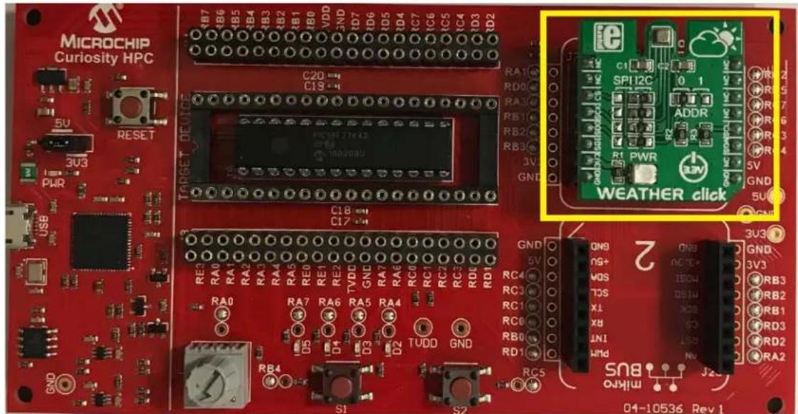
text_image
MICROCHIP Curiosity HPC 5U RESET 3U3 PWR USB C20 C19 TARGET DEVICE C18 C17 RE2 RA0 RA1 RA2 RA3 RA4 RA5 RE0 RE1 RE2 TVDD GND RA7 RA6 RA5 RA4 RA6 RC0 RC1 RC2 RC3 RC4 RD0 RD1 D5 D4 D3 D2 TVDD GND RB4 S1 S2 RG5 C1 C2 SPI12C ADDR R1 PWR GND WEATHER click GND 5V ON9 ON8 ON7 ON6 ON5 ON4 ON3 ON2 ON1 ON0 ON-10536 Rev 1- Connect the MCP2200 to the Curiosity board using jumper wires. Connect one end of a jumper wire to pin RB4 of header J11, and the other end to pin 6 of the MCP2200. Next, connect one end of a jumper wire to the GND pin of header J11, and the other end to pin 3 of the MCP2200. See Figure 2-3 for the connection points. Finally, connect the MCP2200 to a PC using the USB Mini-B 5-pin cable. Note that the PIC device's UART receive line is not used, so no additional wiring is needed.
Figure 2-3. MCP2200 USB-to-UART Connections

text_image
PIN 6 (MCP2200) PIN 3 (MCP2200) GND (PIC®) RB4 (PIC)- Connect the Curiosity HPC to the PC using the USB Micro-B 5-pin cable, as shown in Figure 2-4. This is the final step in the hardware configuration.
Figure 2-4. Curiosity HPC Connection to the PC

text_image
MICROCHIP Curiosity HPC 5V RCSET pWR USB C20 4 C18 4 RE RA0 RA1 RA2 RA3 RA4 RB4 RB5 RB6 RB7 RB8 RB9 RB10 RB11 RB12 RB13 RB14 RB15 RB16 RB17 RB18 RB19 RB20 RB21 RB22 RB23 RB24 RB25 RB26 RB27 RB28 RB29 RB30 RB31 RB32 RB33 RB34 RB35 RB36 RB37 RB38 RB39 RB40 RB41 RB42 RB43 RB44 RB45 RB46 RB47 RB48 RB49 RB50 RB51 RB52 RB53 RB54 RB55 RB56 RB57 RB58 RB59 RB602.2 Software Configuration
-
Download and install the latest MPLAB X IDE. The latest MPLAB X version can be found at http://www.microchip.com/mplab/mplab-x-ide.
-
Download and install the latest MPLAB XC8 compiler. The latest MPLAB XC8 compiler can be found at http://www.microchip.com/mplab/compilers.
-
Open the MPLAB X IDE. On the main toolbar, select Tools, and then select the Plugin tab in the drop-down menu, as shown in Figure 2-5.
Figure 2-5. Tools Drop-Down Menu

text_image
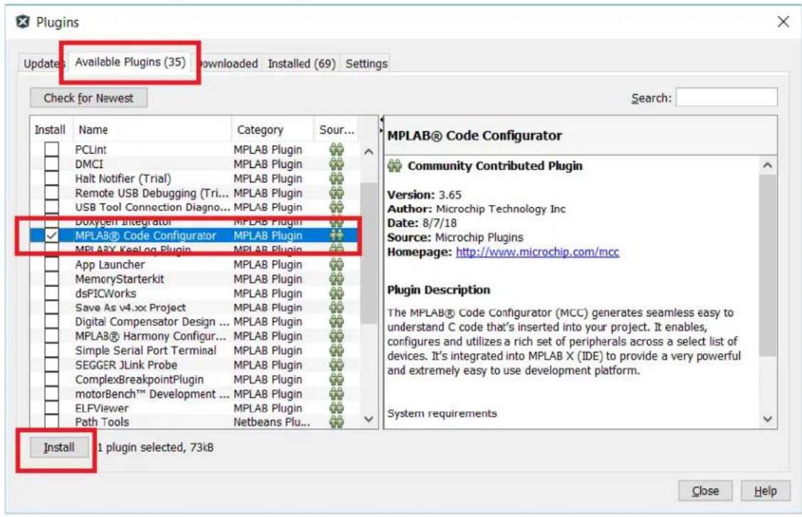
MPLAB X IDE v4.15 - SPI_WEATHERclick_X : free File Edit View Navigate Source Refactor Production Debug Team Tools Window Help Embedded Licenses Templates DTDs and XML Schemas Plugins Plugins Download Options- A new window, Plugins, will open. Under the Available Plugins tab, find the MPLAB Code Configurator selection and add a checkmark to the check box. Press the Install button (see Figure 2-6). This installs the MCC tool used to configure the necessary peripherals contained in this project. Once the install is complete, MPLAB will require a restart to enable the MCC tool.
Figure 2-6. Installing the MCC Plug-in Tool
text_image
Plugins Updates: Available Plugins (35) Downloaded Installed (69) Settings Check for Newest Install Name Category Sour... PCLint MPLAB Plugin DMCI MPLAB Plugin Halt Notifier (Trial) MPLAB Plugin Remote USB Debugging (Tri... MPLAB Plugin) USB Tool Connection Diagno... MPLAB Plugin DOxygen Integrator MPLAB Plugin ✓ MPLAB® Code Configurator MPLAB Plugin MPLAB® Keelog Plugin MPLAB Plugin App Launcher MPLAB Plugin MemoryStarterkit MPLAB Plugin dsPICWorks MPLAB Plugin Save As v4.xx Project MPLAB Plugin Digital Compensator Design ... MPLAB Plugin MPLAB® Harmony Configur... MPLAB Plugin Simple Serial Port Terminal MPLAB Plugin SEGER JLink Probe MPLAB Plugin ComplexBreakpointPlugin MPLAB Plugin motorBench™ Development ... MPLAB Plugin ELFViewer MPLAB Plugin Path Tools Netbeans Plug... Install 1 plugin selected, 73kB Search: MPLAB® Code Configurator Community Contributed Plugin Version: 3.65 Author: Microchip Technology Inc Date: 8/7/18 Source: Microchip Plugins Homepage: http://www.microchip.com/mcc Plugin Description The MPLAB® Code Configurator (MCC) generates seamless easy to understand C code that's inserted into your project. It enables, configures and utilizes a rich set of peripherals across a select list of devices. It's integrated into MPLAB X (IDE) to provide a very powerful and extremely easy to use development platform. System requirements Close Help- Create a new project in MPLAB X. Click on File, then "New Project" from the drop-down menu, as shown in Figure 2-7.
Figure 2-7. Create a New Project

text_image
MPLAB X IDE v4.15 File Edit View Navigate Source Refactor Production Debug Team Tools Window Help New Project... Ctrl+Shift+N New File... Ctrl+N Open Project... Ctrl+Shift+O Open Recent Project > Import > Close Project Close Other Projects Close All Projects Open File... Open Recent File > Project Groups... Project Properties Save Ctrl+S Save As... Save All Ctrl+Shift+S Page Setup... Print... Ctrl+Alt+Shift+P Print to HTML... Exit Open>- The New Project window will open. Select "Standalone Project" in the Projects window and click Next > (see Figure 2-8).
Figure 2-8. Choose Type of Project

text_image
New Project Steps 1. Choose Project 2. ... Choose Project Filter: Categories: Microchip Embedded Other Embedded Samples Projects. Standalone Project Existing MPLAB IDE v8 Project Prebuilt (Hex, Loadable Image) Project User Makefile Project Library Project Import Atmel Start Project Import Atmel Studio Project Description: Creates a new standalone application project. It uses an IDE-generated makefile to build your project. < Back Next > Finish Cancel Help- In the Select Device window, select PIC18F25K42 from the "Device:" drop-down menu, as shown in Figure 2-9. Click Next >.
Figure 2-9. Select Device
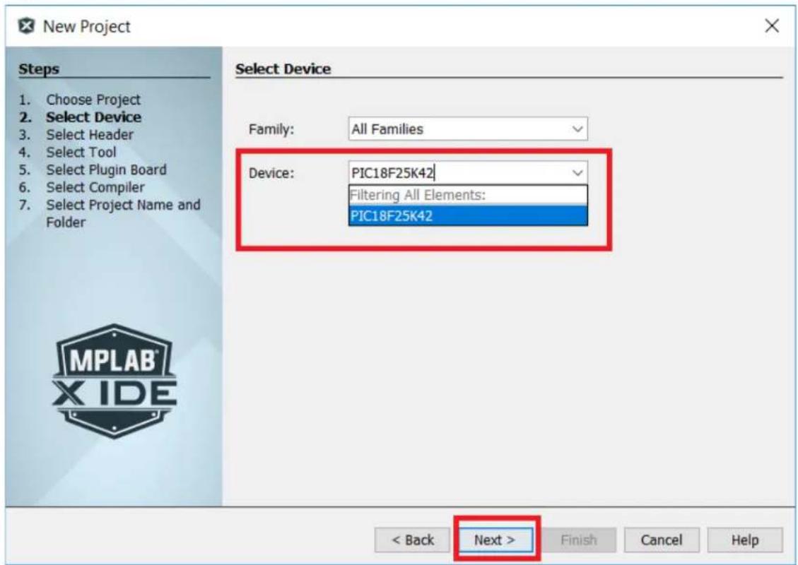
text_image
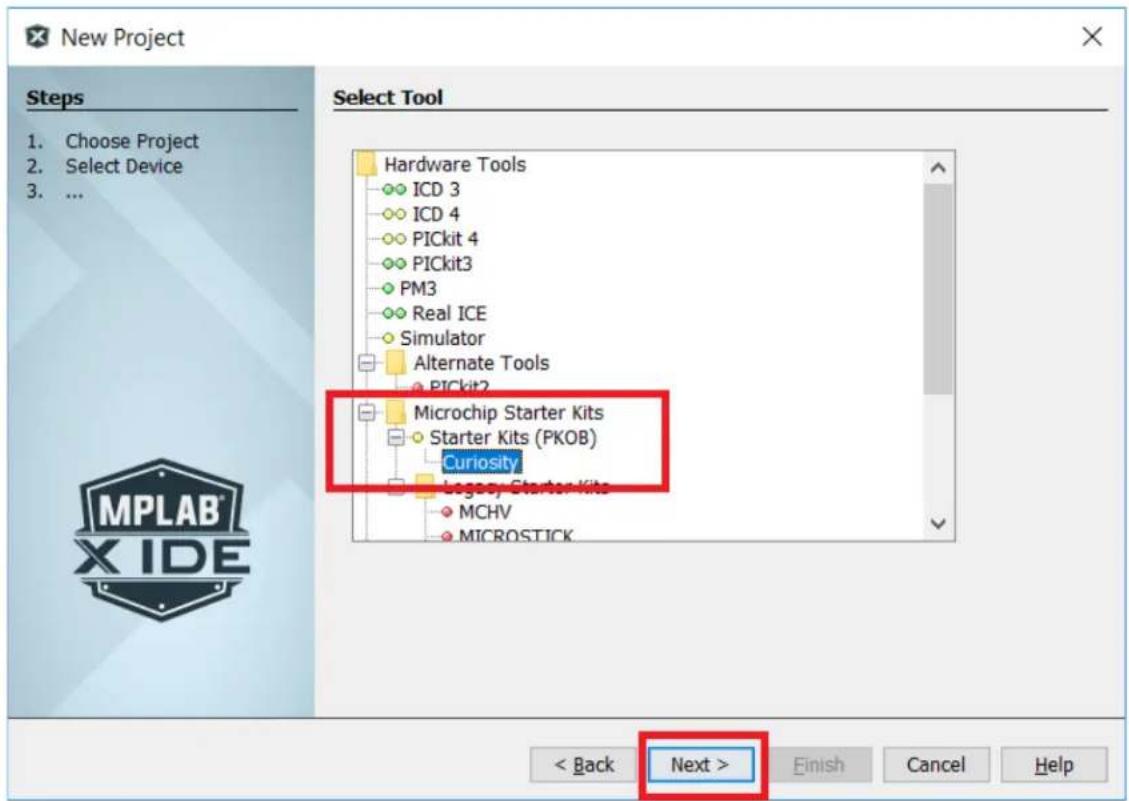
New Project Steps Choose Project Select Device Select Header Select Tool Select Plugin Board Select Compiler Select Project Name and Folder Select Device Family: All Families Device: PIC18F25K42 Filtering All Elements: PIC18F25K42 < Back Next > Finish Cancel Help MPLAB X IDE- In the Select Tool window, under the Microchip Starter Kits > Starter Kits (PKOB) menu selection, click Curiosity (see Figure 2-10). Click Next >. It is important to note that the Curiosity HPC board must be connected to the PC for MPLAB X to recognize it as a tool. The Curiosity selection will not be visible if the board is not connected to the PC.
Figure 2-10. Select Tool
text_image
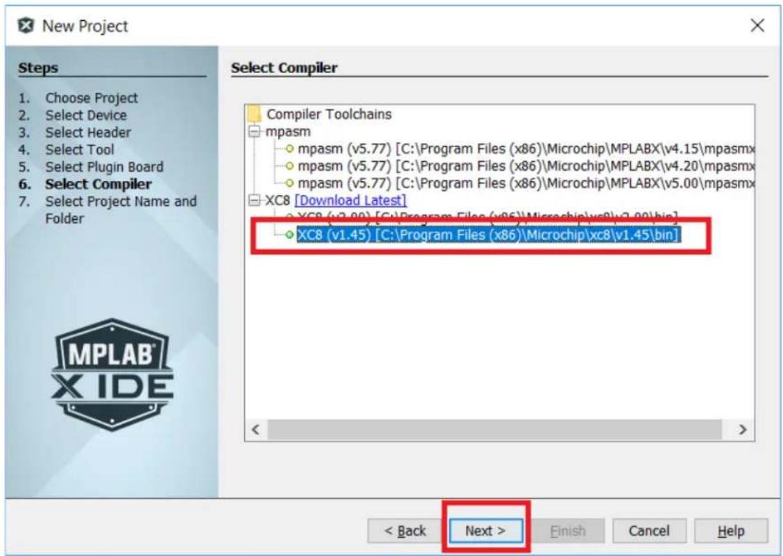
New Project Steps 1. Choose Project 2. Select Device 3. ... Select Tool Hardware Tools ICD 3 ICD 4 PICkit 4 PICkit3 PM3 Real ICE Simulator Alternate Tools PICkit2 Microchip Starter Kits Starter Kits (PKOB) Curiosity Legacy Starter Kits MCHV MICROSTICK < Back Next > Finish Cancel Help- In the Select Compiler window, select the desired XC compiler under the XC8 menu list (see Figure 2-11). Click Next >. Note that Figure 2-11 shows two XC8 compiler choices. XC8 (v2.00) must be used with MPLAB X v.5.00, while XC8 (v1.45) is compatible with the MPLAB X v.4.15 utilized in this application.
Figure 2-11. Select Compiler
text_image
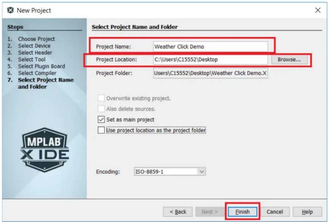
New Project Steps 1. Choose Project 2. Select Device 3. Select Header 4. Select Tool 5. Select Plugin Board 6. Select Compiler 7. Select Project Name and Folder Select Compiler Compiler Toolchains mpasm mpasm (v5.77) [C:\Program Files (x86)\Microchip\MPLABX\v4.15\mpasmx mpasm (v5.77) [C:\Program Files (x86)\Microchip\MPLABX\v4.20\mpasmx mpasm (v5.77) [C:\Program Files (x86)\Microchip\MPLABX\v5.00\mpasmx XC8 [Download Latest] XC8 (v3.00) [C:\Program Files (x86)\Microchip\xc8\v3.00\bin] XC8 (v1.45) [C:\Program Files (x86)\Microchip\xc8\v1.45\bin] < Back Next > Finish Cancel Help- In the Select Project Name and Folder window, type the name of the project into the "Project Name:" text box. Next, choose the location to store the project. For this application, the Desktop file location was chosen (see Figure 2-12). After the project name and location have been determined, click Finish.
Figure 2-12. Select Project Name and Folder
text_image
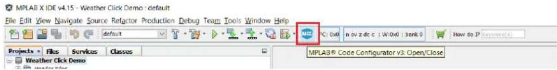
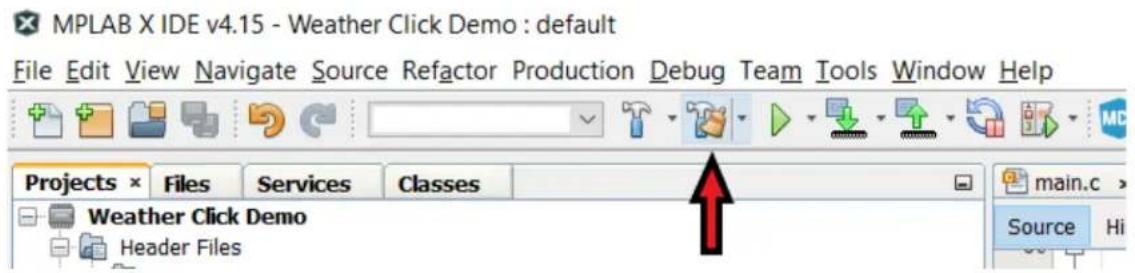
New Project Steps 1. Choose Project 2. Select Device 3. Select Header 4. Select Tool 5. Select Plugin Board 6. Select Compiler 7. Select Project Name and Folder Select Project Name and Folder Project Name: Weather Click Demo Project Location: C:\Users\C15552\Desktop Browse... Project Folder: Users\C15552\Desktop\Weather Click Demo.X Overwrite existing project. Also delete sources. Set as main project Use project location as the project folder Encoding: ISO-8859-1 < Back Next > Finish Cancel Help- At this point, the PIC microcontroller is ready for configuration. The MCC tool is used to configure the peripherals needed for the application and generate the necessary driver files. Click on the MCC icon in the MPLAB X toolbar, as shown in Figure 2-13. This opens the MCC tool.
Figure 2-13. MCC Icon
text_image
MPLAB X IDE v4.15 - Weather Click Demo : default File Edit View Navigate Source Refactor Production Debug Team Tools Window Help default NICE PC: 0x0 n ov z dc c : W:0x0 : bank 0 How do P (Keywords) Projects Files Services Classes Weather Click Demo MPLAB® Code Configurator v3: Open/Close- MCC will default to the System Module window when it opens. There are two tabs within this window: Easy Setup and Registers. The Easy Setup tab allows for simple changes to the system oscillator, configures the Windowed Watchdog Timer, and enables Low-Voltage Programming (LVP). The Registers tab allows for changes to be made to the Configuration Words, oscillator registers, Peripheral Module Disable (PMD) registers, and the Windowed Watchdog Timer registers. The Registers tab has to be used when the default settings of the above registers cannot be utilized by the application. For this application, the system can be configured using the Easy Setup tab. The settings are as follows:
- In the INTERNAL OSCILLATOR window, under the "Oscillator Select" drop-down menu, select HFINTOSC. When HFINTOSC is selected, MCC automatically configures the "HF Internal Clock" and "Clock Divider" selections to achieve a 1 MHz system clock, as shown in Figure 2-14.
Figure 2-14. Oscillator Selection

text_image
Pin Module × System Module × Interrupt Module × System Module Easy Setup Registers INTERNAL OSCILLATOR Current System clock 1 MHz Oscillator Select HFINTOSC External Clock Select Oscillator not enabled HF Internal Clock 4_MHz →PLL Capable Frequency External Clock 1 MHz Clock Divider 4- The WWDT and Programming windows can be left in their default states.
- Next, in the Device Resources window, scroll down to the SPI selection, click on the arrow next to the SPI selection, click the arrow next to SPI1, and double click on the SPI1 [PIC10/PIC12/PIC16/PIC18 MCUs by Microchip Technology, Inc.] selection. A new tab will appear named SPI1. The SPI1 window contains the Easy Setup and Registers tabs. For this application, the Easy Setup tab is used.
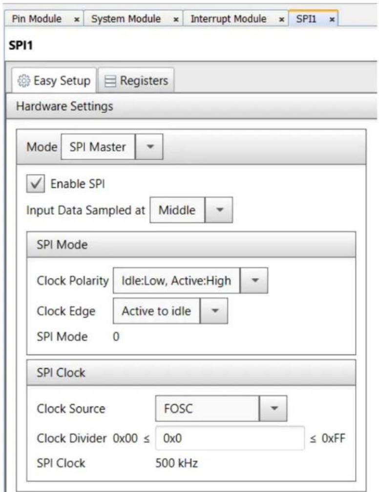
Configure the SPI as follows (see Figure 2-15):
- In the "Mode" drop-down menu, select SPI Master.
-
Leave the "Enable SPI" check box checked (default).
-
In the "Input Data Sampled at" drop-down menu, select Middle (default).
• In the "Clock Polarity" drop-down menu, select Idle:Low, Active:High. - In the "Clock Edge" drop-down menu, select Active to idle.
- In the "Clock Source" drop-down menu, select FOSC (default).
- In the "Clock Divider" box, enter 0x0 (no divider).
Figure 2-15. SPI Configuration
text_image
Pin Module × System Module × Interrupt Module × SPI1 SPI1 Easy Setup Registers Hardware Settings Mode SPI Master Enable SPI Input Data Sampled at Middle SPI Mode Clock Polarity Idle:Low, Active:High Clock Edge Active to idle SPI Mode 0 SPI Clock Clock Source FOSC Clock Divider 0x00 ≤ 0x0 ≤ 0xFF SPI Clock 500 kHz-
Under the Device Resources window, scroll down to "UART", click on the arrow next to "UART", then click on the arrow next to "UART1", and double click on the UART1 [PIC10/PIC12/PIC16/PIC18 MCUs by Microchip Technology, Inc.] selection. A new tab will appear named UART1. Configure the SPI in the Easy Setup tab as follows (see Figure 2-16):
-
In the "Mode" drop-down menu, select Asynchronous 8-bit mode (default).
- Leave the "Baud Rate:" setting at 9600 (default).
- Leave the "Enable UART" check box checked (default).
- Add a checkmark in the "Enable Transmit" check box.
-
Leave the “Transmit Polarity” and “Receive Polarity” drop-down menu selections as ‘not inverted’ (default).
-
Add a checkmark to the "Redirect STDIO to UART" check box.
- Leave the “Transmit Polarity” and “Receive Polarity” drop-down menu selections as ‘not inverted’ (default).
- Add a checkmark to the "Redirect STDIO to UART" check box.
Figure 2-16. UART Configuration

text_image
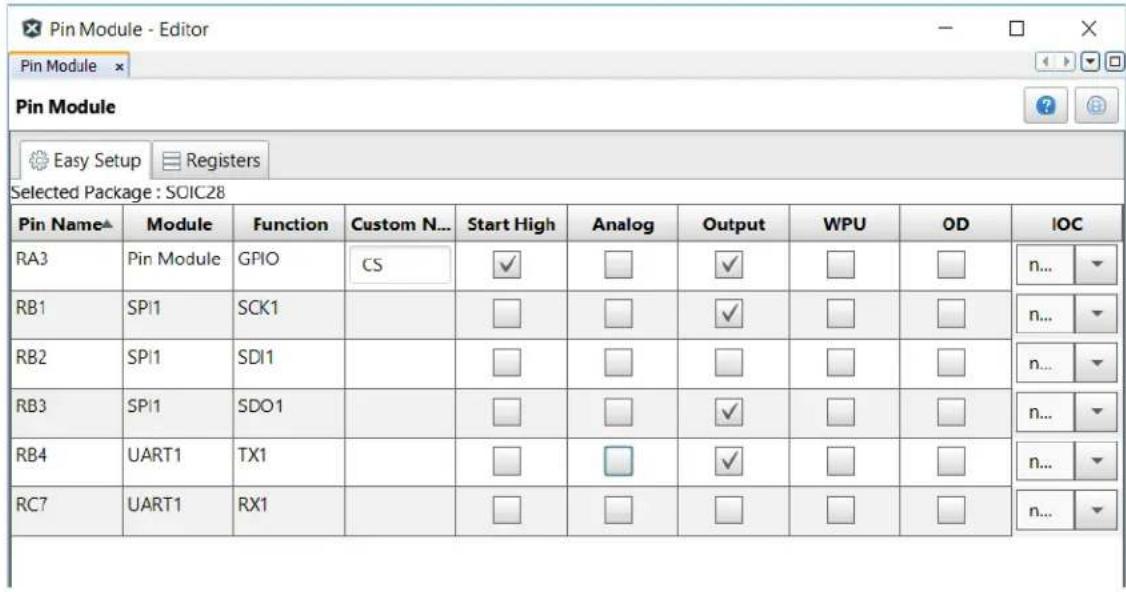
Pin Module System Module Interrupt Module SPI1 UART1 UART1 Easy Setup Registers Hardware Settings Mode Asynchronous 8-bit mode Enable UART Baud Rate: 9600 Error: 0.160 % Enable Transmit Transmit Polarity: not inverted Enable Receive Receive Polarity: not inverted Auto-Baud Detection Receiver Address: 0x0 Enable UART Interrupts Software Settings Redirect STDIO to UART Software Transmit Buffer Size 8 Software Receive Buffer Size 8- In the Project Resources window, click on Pin Module. This opens the Pin Module tab, allowing for the configuration of the I/Os used for the application. The user will need to change the SPI pins from the default settings, and add the UART TX pin.
Under the Registers tab, change the following:
- Register RB1PPS – enter 0x1E (SCK1 output).
- Register RB3PPS – enter 0x1F (SDO output).
- Register RB4PPS – enter 0x13 (TX output).
- Register RC3PPS – change the value to 0x0 (unused).
- Register SPI1SCKPPS – change the value to 0x0 (SCK input not used).
- Register SPI1SDIPPS – change the value to 0x0A (SDI input on RB1).
- Register SPI1SSPPS – change the value to 0x0 (SS input not used).
In the Pin Manager: Grid View window, click on the Port A number 3 box in the "Pin Module > GPIO > output" selection row (see Figure 2-17).
Switch from the Registers tab to the Easy Setup tab in the Pin Module window, then make the following changes (see Figure 2-18):
- Pin RA3 – In the “Custom Name” column, change the name to CS, add a checkmark to the “Start High” check box, and remove the checkmark from the “Analog” check box.
- Pin RB3 – Remove the checkmark from the "Analog" check box.
- Pin RB4 – Remove the checkmark from the "Analog" check box.
Figure 2-17. Pin Manager: Grid View Window
| Pin Manager: Grid View x | ||||||||||||||||||||||||||||
| Package: | SOIC28 | ✓ | Pin No: | 2 | 3 | 4 | 5 | 6 | 7 | 10 | 9 | 21 | 22 | 23 | 24 | 25 | 26 | 27 | 28 | 11 | 12 | 13 | 14 | 15 | 16 | 17 | 18 | 1 |
| Port A ▼ | Port B ▼ | Port C ▼ | E | |||||||||||||||||||||||||
| Module | Function | Direction | 0 | 1 | 2 | 3 | 4 | 5 | 6 | 7 | 0 | 1 | 2 | 3 | 4 | 5 | 6 | 7 | 0 | 1 | 2 | 3 | 4 | 5 | 6 | 7 | 3 | |
| OSC | CLKOUT | output | ||||||||||||||||||||||||||
| Pin Module ▼ | GPIO | input | ||||||||||||||||||||||||||
| GPIO | output | |||||||||||||||||||||||||||
| RESET | MCLR | input | ||||||||||||||||||||||||||
| SPI1 ▼ | SCK1 | in/out | ||||||||||||||||||||||||||
| SDI1 | input | |||||||||||||||||||||||||||
| SDO1 | output | |||||||||||||||||||||||||||
| UART1 ▼ | CTS1 | input | ||||||||||||||||||||||||||
| RTS1 | output | |||||||||||||||||||||||||||
| RX1 | input | |||||||||||||||||||||||||||
| TX1 | output | |||||||||||||||||||||||||||
| TXDE1 | output | |||||||||||||||||||||||||||
Figure 2-18. Pin Module Easy Setup Window
text_image
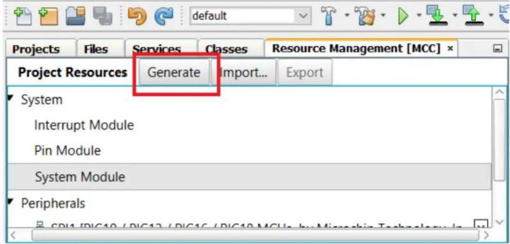
Pin Module - Editor Pin Module Pin Module Easy Setup Registers Selected Package : SOIC28 Pin Name▲ Module Function Custom N... Start High Analog Output WPU OD IOC RA3 Pin Module GPIO CS ✓ □ ✓ □ □ n... ▼ RB1 SPI1 SCK1 □ □ ✓ □ □ n... ▼ RB2 SPI1 SDI1 □ □ □ □ □ n... ▼ RB3 SPI1 SDO1 □ □ ✓ □ □ n... ▼ RB4 UART1 TX1 □ □ ✓ □ □ n... ▼ RC7 UART1 RX1 □ □ □ □ □ n... ▼- In the Project Resources window, click the Generate button (see Figure 2-19). MCC creates a project that contains the driver files for the peripherals that had been configured.
Figure 2-19. MCC Generate Button
MPLAB X IDE v4.15 - Weather Click Demo : default
File Edit View Navigate Source Refactor Production Debug Team Tools Window
text_image
default Projects Files Services Classes Resource Management [MCC] * Project Resources Generate Import... Export System Interrupt Module Pin Module System Module Peripherals CPI1 /D/C10 / D/C12 / D/C16 / D/C10/MCU by Microchip Technology in- At this point, the user has all the necessary files to run the application, except for the drivers for the Weather Click. Additionally, the main.c file needs to have some routines added.
To add the Weather Click drivers and main.c code, follow these steps in MPLAB X:
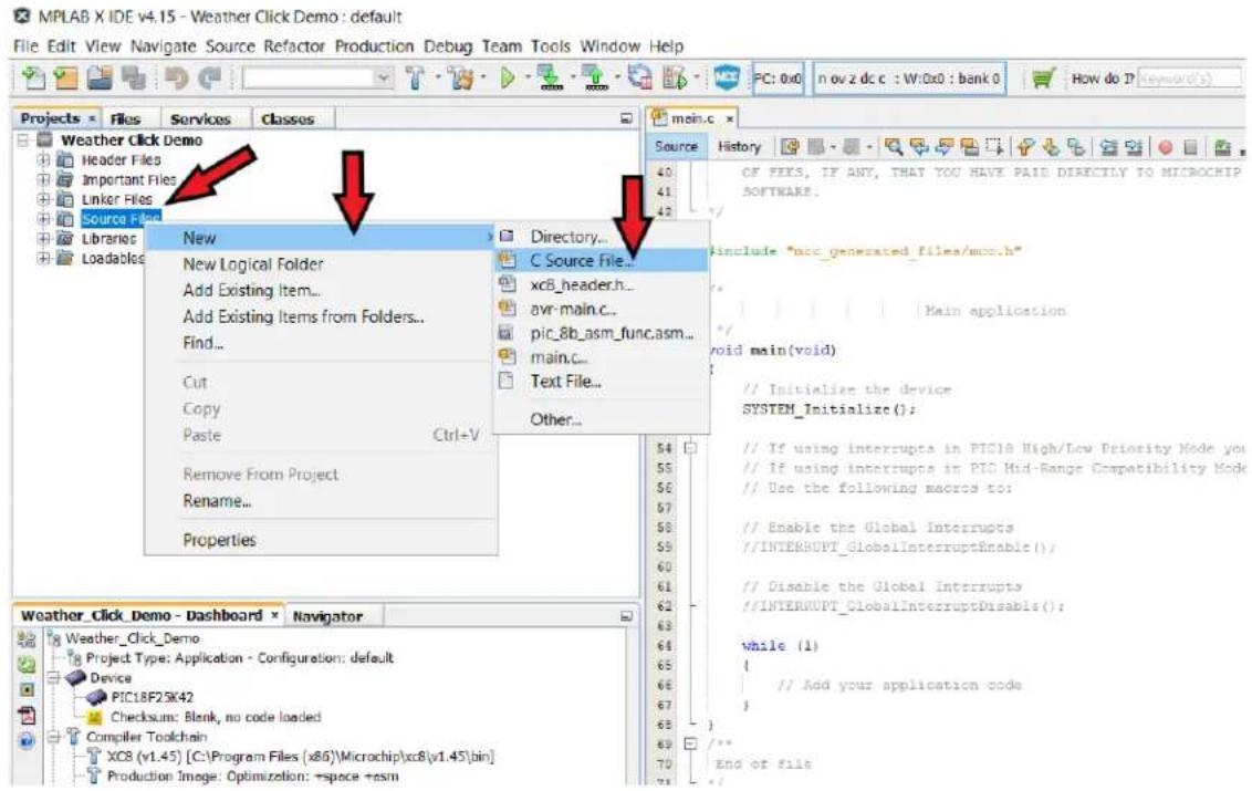
a. In the Projects tab, right-click on Source Files, then drag the mouse over New, and click on C Source File (see Figure 2-20).
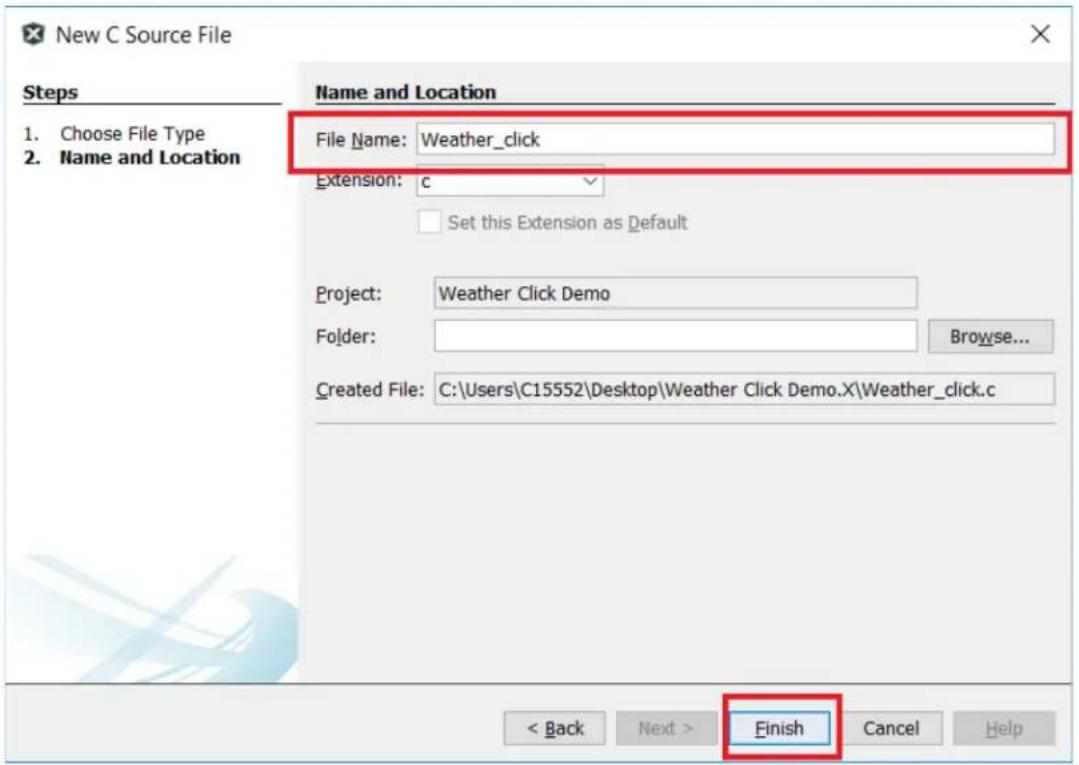
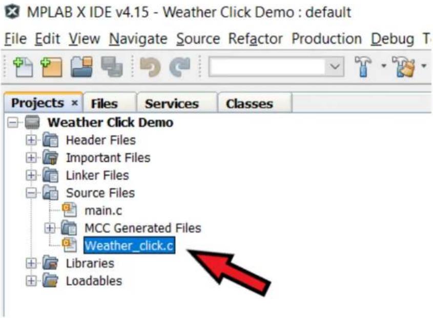
b. The New C Source File window will open. In the "File Name" text box, enter Weather_click as the C file name (see Figure 2-21). The remaining text boxes do not need modification unless a separate file location is desired. Once the file name has been entered, click the Finish button. The new file will appear under the Source Files file menu, as shown in Figure 2-22.
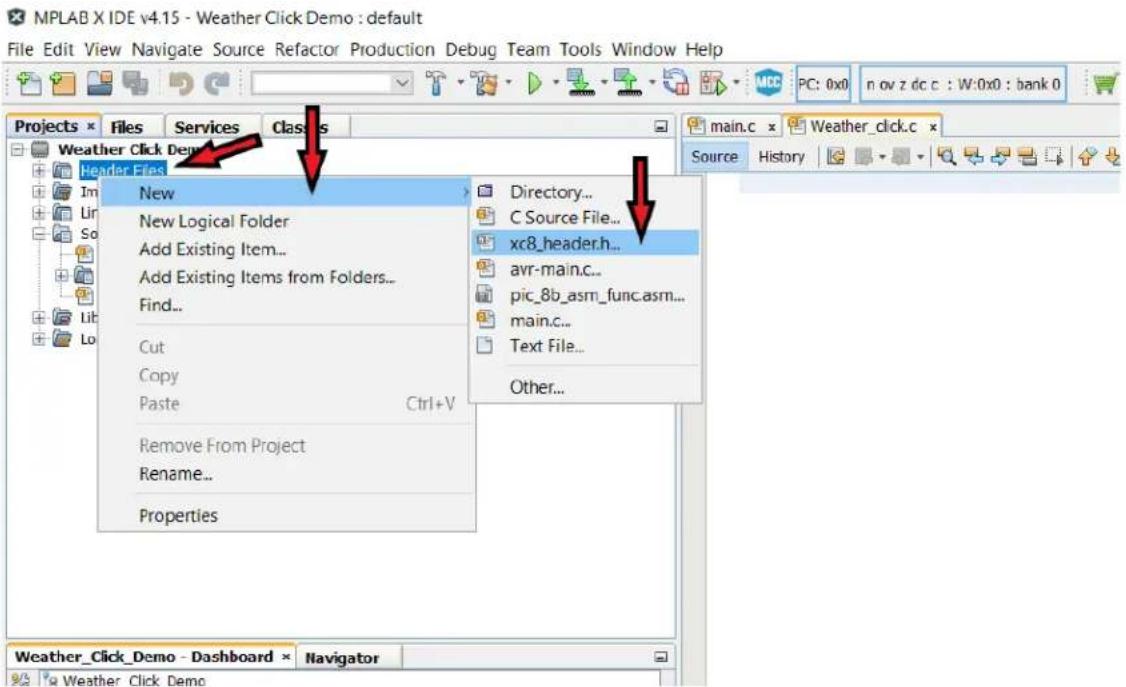
c. Next, the user will essentially perform steps 'a' and 'b' again for the header file. In the Projects tab, right-click on Header Files, then drag the mouse over "New", and click on xc8_header.h (see Figure 2-23).
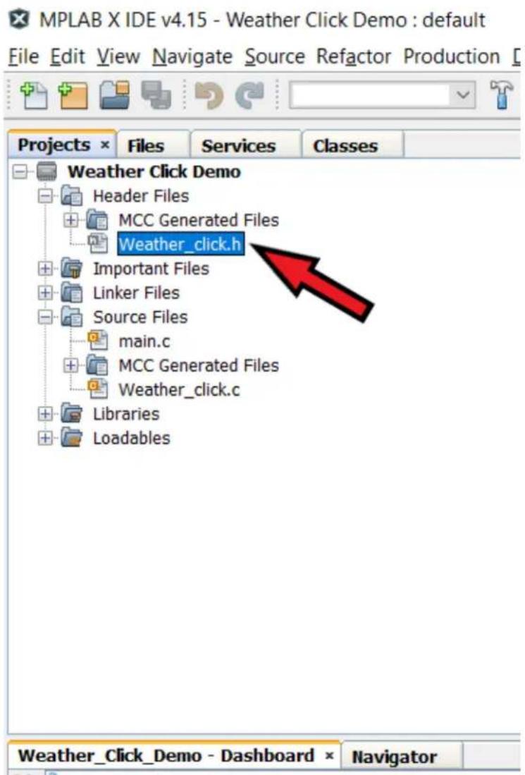
d. The New xc8_header.h window will open. In the "File Name" text box, enter Weather_click as the header file name (see Figure 2-24). Click the Finish button, and the new file will appear under the "Header Files" file menu, as shown in Figure 2-25.
e. The BME280 sensor's data sheet provides the necessary compensation routines and recommends these routines be used for calculations. For simplicity, these routines have been extracted from the data sheet and modified for this application. Copy the entire code example in Example 2-1 and paste into the newly created Weather_click.c file.
f. Copy the entire code example in Example 2-2 and paste into the newly created Weather_click.h file.
g. Copy the entire code example in Example 2-8 and paste into the project's main.c file.
h. Click on the Clean and Build Main Project button (see Figure 2-26). If all the steps have been followed, there will be no errors. If there are any errors, confirm that the code examples were copied properly.
i. Click on the Make and Program Device Main Project button to program the PIC device (see Figure 2-27).
Figure 2-20. Creating the weather_click.c File
text_image
MPLAB X IDE v4.15 - Weather Click Demo : default File Edit View Navigate Source Refactor Production Debug Team Tools Window Help PC: 0x0 n ov z dc c : W:0x0 : bank 0 How do ? (Keyword's) Projects Files Services Classes Weather Click Demo Header Files Important Files Linker Files Source Files Libraries Loadables New New Logical Folder Add Existing Item... Add Existing Items from Folders... Find... Cut Copy Paste Ctrl+V Remove From Project Rename... Properties Directory... C Source File... xcB_header.h... avr-main.c... pic_8b_asm_func.asm... main.c... Text File... Other... CF FEES, IF ANY, THAT YOU HAVE PAID DIRECTLY TO MICROCHIP SOFTWARE. include "mcc_generated_files/mcc.h" Main application void main(void) // Initialize the device SYSTEM_Initialize( ); // If using interrupts in PIC18 High/Low Priority Mode you // If using interrupts in PIC Mid-Range Compatibility Mode // Use the following macros to: // Enable the Global Interrupts // INTERRUPT_GlobalInterruptEnable( ); // Disable the Global Interrupts // INTERRUPT_GlobalInterruptDisable( ); while (1) { // Add your application code } End of fileFigure 2-21. New C Source File Window
text_image
New C Source File Steps 1. Choose File Type 2. Name and Location Name and Location File Name: Weather_click Extension: c Set this Extension as Default Project: Weather Click Demo Folder: Browse... Created File: C:\Users\C15552\Desktop\Weather Click Demo.X\Weather_click.c < Back Next > Finish Cancel HelpFigure 2-22. Generated Weather_click.c File in Projects Window
text_image
MPLAB X IDE v4.15 - Weather Click Demo : default File Edit View Navigate Source Refactor Production Debug T Projects × Files Services Classes Weather Click Demo Header Files Important Files Linker Files Source Files main.c MCC Generated Files Weather_click.c Libraries LoadablesFigure 2-23. Creating the Weather_click.h File
text_image
MPLAB X IDE v4.15 - Weather Click Demo : default File Edit View Navigate Source Refactor Production Debug Team Tools Window Help PC: 0x0 n ov z dc c : W:0x0 : bank 0 Projects × Files Services Classes Weather Click Demo Header Files New New Logical Folder Add Existing Item... Add Existing Items from Folders... Find... Cut Copy Paste Ctrl+V Remove From Project Rename... Properties Directory... C Source File... xc8_header.h... avr-main.c... pic_8b_asm_func.asm... main.c... Text File... Other... Weather_ClickDemo - Dashboard × Navigator Source HistoryFigure 2-24. New xc8_header.h File Window

text_image
New xc8_header.h Steps 1. Choose File Type 2. Name and Location Name and Location File Name: Weather_click Extension: h Set this Extension as Default Project: Weather Click Demo Folder: Browse... Created File: C:\Users\C15552\Desktop\Weather Click Demo.X\Weather_click.h < Back Next > Finish Cancel HelpFigure 2-25. Generated Weather_click.h File in Projects Window
text_image
MPLAB X IDE v4.15 - Weather Click Demo : default File Edit View Navigate Source Refactor Production Projects × Files Services Classes Weather Click Demo Header Files MCC Generated Files Weather_click.h Important Files Linker Files Source Files main.c MCC Generated Files Weather_click.c Libraries Loadables Weather_Click_Demo - Dashboard × NavigatorFigure 2-26. Clean and Build Main Project Button
text_image
MPLAB X IDE v4.15 - Weather Click Demo : default File Edit View Navigate Source Refactor Production Debug Team Tools Window Help Projects × Files Services Classes main.c > Weather Click Demo Header Files Source HiFigure 2-27. Make and Program Device Main Project Button

text_image
MPLAB X IDE v4.15 - Weather Click Demo : default File Edit View Navigate Source Refactor Production Debug Team Tools Window Help Projects × Files Services Classes main.c × Weather Click Demo Header Files Source History-
Download and install a free PC terminal program. The free "Tera Term" open-source software terminal emulator was chosen for this project. The Tera Term program can be downloaded here: https://osdn.net/projects/ttssh2/releases/.
-
Open the terminal program. Select the COM Port that is connected to the MCP2200. Figure 2-28 shows the COM Port selections using the Tera Term program. Click OK.
Figure 2-28. COM Port Selection Window

text_image
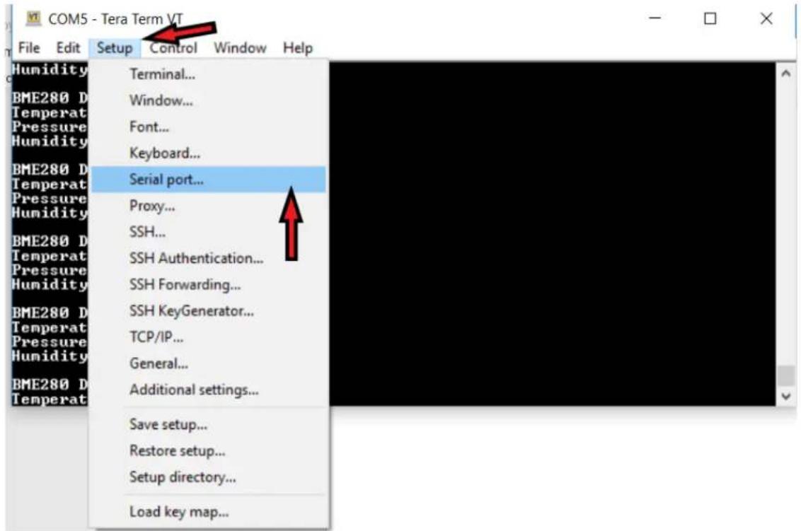
Tera Term: New connection ○TCP/IP Host: myhost.example.com ✓History Service: ○Telnet TCP port#: 22 ○SSH SSH version: SSH2 ○Other Protocol: UNSPEC ●Serial Port: COM3: Intel(R) Active Management Tec COM3: Intel(R) Active Management Technology COM5: USB Serial Device (COM5) OK Cancel Help- Ensure that the terminal program is configured to match the PIC device's UART settings. If using the Tera Term program, click on the Setup tab, and click on Serial port..., as shown in Figure 2-29. The Tera Term: Serial Port Setup window will appear (see Figure 2-30). The serial port settings are as follows (regardless of the terminal program used):
• Baud rate: 9600
- Data: 8 bit
- Parity: none
- Stop: 1 bit
- Flow control: none
Figure 2-29. Serial Port Setup Tab
text_image
COM5 - Tera Term VT File Edit Setup Control Window Help Humidity Terminal... BME280 D Temperat Pressure Humidity Window... Font... Keyboard... BME280 D Temperat Pressure Humidity Serial port... Proxy... SSH... SSH Authentication... BME280 D Temperat Pressure Humidity SSH Forwarding... BME280 D Temperat Pressure Humidity SSH KeyGenerator... TCP/IP... General... BME280 D Temperat Additional settings... Save setup... Restore setup... Setup directory... Load key map...Figure 2-30. Tera Term Serial Port Setup Window with Correct Settings
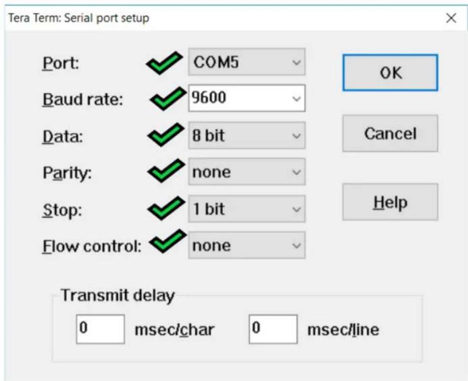
text_image
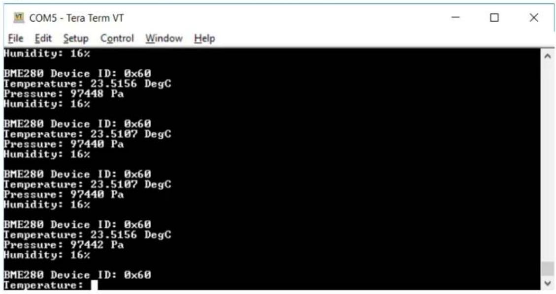
Tera Term: Serial port setup Port: COM5 Baud rate: 9600 Data: 8 bit Parity: none Stop: 1 bit Flow control: none OK Cancel Help Transmit delay 0 msec/char 0 msec/line- At this point, the PIC device will be transmitting the environmental data to the terminal window for viewing, as shown in Figure 2-31.
Figure 2-31. Terminal Window with Environmental Data
text_image
COM5 - Tera Term VT File Edit Setup Control Window Help Humidity: 16% BME280 Device ID: 0x60 Temperature: 23.5156 DegC Pressure: 97448 Pa Humidity: 16% BME280 Device ID: 0x60 Temperature: 23.5107 DegC Pressure: 97440 Pa Humidity: 16% BME280 Device ID: 0x60 Temperature: 23.5107 DegC Pressure: 97440 Pa Humidity: 16% BME280 Device ID: 0x60 Temperature: 23.5156 DegC Pressure: 97442 Pa Humidity: 16% BME280 Device ID: 0x60 Temperature:Example 2-1. Weather_click.c Code
#include <xc.h>
#include "Weather_click.h"
#include "mcc_generated_files/mcc.h"
#include "mcc_generated_files/uart1.h"

uint8_t cmd_deviceID[2] = {0xD0, DUMMY_DATA};
uint8_t deviceID[2];
uint8_t cmd_initialize[7] = {0x72, 0x01, 0x74, 0x25, 0x75, 0x80, DUMMY_DATA};
uint8_t cmd_temp[4] = {0xFA, 0xFB, 0xFC, DUMMY_DATA};
uint8_t temp[4];
uint8_t cmd_press[4] = {0xF7, 0xF8, 0xF9, DUMMY_DATA};
uint8_t press[4];
uint8_t cmd_hum[3] = {0xFD, 0xFE, DUMMY_DATA};
uint8_t hum[3];
uint8_t cmd_uDigT[3] = {0x88, 0x89, DUMMY_DATA};
int8_t cmd_sDigT[5] = {0x8A, 0x8B, 0x8C, 0x8D, DUMMY_DATA}
uint8_t uDigT[3];
int8_t sDigT[5];
uint8_t cmd_uDigP[3] = {0x8E, 0x8F, DUMMY_DATA};
uint8_t cmd_sDigP[17] = {0x90, 0x91, 0x92, 0x93, 0x94, 0x95, 0x96, 0x97, 0x98, 0x99, 0x9A, 0x9B, 0x9C, 0x9D, 0x9E, 0x9F, DUMMY_DATA};

uint8_t uDigP[3];
uint8_t sDigP[17];
uint8_t cmd_uDigH[3] = {0xA1, 0xE3, DUMMY_DATA};
int8_t cmd_sDigH[7] = {0xE1, 0xE2, 0xE4, 0xE5, 0xE6, 0xE7, DUMMY_DATA};
uint8_t uDigH[3];
int8_t sDigH[7];
int32_t t_fine;
double T,P;
uint32_t H;
typedef union {
    int32_t raw;
    struct {
    signed byte0 : 8;
    signed byte1 : 8;
    signed byte2 : 8;
    signed byte3 : 8;
};
} raw_data_t;
raw_data_t temp_raw, press_raw, hum_raw;
Example 2-2. Weather_click.c Code
// Section: MikroElektronika WEATHER click APIs
void WEATHERclick_Config(void)
{
    uint8_t i;
    CS_SetLow();
    for (i = 0; i < 7; i++)
    {
    SPI1_Exchange8bit(cmd_initialize[i]);
    }
    CS_SetHigh();
}

void WEATHERclick_ReadID(void)
{
    uint8_t i;
    CS_SetLow();
    for (i = 0; i < 2; i++)
    {
    deviceID[i] = SPI1_Exchange8bit(cmd_deviceID[i]);
    }
    CS_SetHigh();
}

void WEATHERclick_ReadTempParameters(void)
{
    uint8_t i;
    uint8_t j;

    CS_SetLow();
    for (i = 0; i < 3; i++)
    {
    uDigT[i] = SPI1_Exchange8bit(cmd_uDigT[i]);
    }
    CS_SetHigh();

    CS_SetLow();
    for (j = 0; j < 5; j++)
    {
    sDigT[j] = SPI1_Exchange8bit(cmd_sDigT[j]);
    }
    CS_SetHigh();
}
Example 2-3. Weather_click.c Code
void WEATHERclick_ReadPressParameters(void)
{
    uint8_t i;
    uint8_t j;

    CS_SetLow();
    for (i = 0; i < 3; i++)
    {
    uDigP[i] = SPI1_Exchange8bit(cmd_uDigP[i]);
    }
    CS_SetHigh();

    CS_SetLow();
    for (j = 0; j < 17; j++)
    {
    sDigP[j] = SPI1_Exchange8bit(cmd_sDigP[j]);
    }
    CS_SetHigh();
}
void WEATHERclick_ReadHumParameters(void)
{
    uint8_t i;
    uint8_t j;

    CS_SetLow();
    for (i = 0; i < 3; i++)
    {
    uDigH[i] = SPI1_Exchange8bit(cmd_uDigH[i]);
    }
    CS_SetHigh();

    CS_SetLow();
    for (j = 0; j < 7; j++)
    {
    sDigH[j] = SPI1_Exchange8bit(cmd_sDigH[j]);
    }
    CS_SetHigh();
}
Example 2-4. Weather_click.c Code
void WEATHERclick_ReadTemp(void)
{
    uint8_t i;
    CS_SetLow();
    for (i = 0; i < 4; i++)
    {
    temp[i] = SPI1_Exchange8bit(cmd_temp[i]);
    }
    CS_SetHigh();
}

void WEATHERclick_ReadPress(void)
{
    uint8_t i;
    CS_SetLow();
    for (i = 0; i < 4; i++)
    {
    press[i] = SPI1_Exchange8bit(cmd_press[i]);
    }
    CS_SetHigh();
}

void WEATHERclick_ReadHum(void)
{
    uint8_t i;
    CS_SetLow();
    for (i = 0; i < 3; i++)
    {
    hum[i] = SPI1_Exchange8bit(cmd_hum[i]);
    }
    CS_SetHigh();
}

void WEATHERclick_PrintResults(void)
{
    printf("\r\nBME280 Device ID:0x%x\r\n", deviceID[1]);
    printf("Temperature:%g", T);
    printf("DegC\r\n");
    printf("Pressure:%g", P);
    printf("Pa\r\n");
    printf("Humidity:%d", H);
    printf("%%\r\n");
}
Example 2-5. Weather_click.c Code
void WEATHERclick_TempCalc(void)
{
    double var1, var2;
    temp_raw.byte2 = temp[1];
    temp_raw.byte1 = temp[2];
    temp_raw.byte0 = temp[3];
    temp_raw.raw = temp_raw.raw >> 4;

    uint16_t digT1 = (uDigT[2] << 8) + (uDigT[1]);
    int16_t digT2 = (sDigT[2] << 8) + (sDigT[1]);
    int16_t digT3 = (sDigT[4] << 8) + (sDigT[3]);

    var1 = (((double)temp_raw.raw) / 16384.0 - ((double)digT1) / 1024.0) * ((double)digT2);
    var2 = (((double)temp_raw.raw) / 131072.0 - ((double)digT1) / 8192.0) * (((double)temp_raw.raw) / 131072.0 - ((double)digT1) / 8192.0)) * ((double)digT3);
    t_fine = (int32_t) (var1 + var2);
    T = (var1 + var2) / 5120.0;
}

void WEATHERclick_HumCalc(void)
{
    int32_t var1;
    hum_raw.byte1 = hum[1];
    hum_raw.byte0 = hum[2];
    uint8_t digH1 = uDigH[1];
    int16_t digH2 = (sDigH[2] << 8) + (sDigH[1]);
    uint8_t digH3 = uDigH[2];
    int16_t digH4 = (sDigH[3] << 4) + (sDigH[4] & 0x0F);
    int16_t digH5 = (sDigH[5] << 4) + ((sDigH[4] >> 4) & 0x0F);
    int8_t digH6 = sDigH[6];

    var1 = (t_fine - ((int32_t) 76000));
    var1 = (((temp_raw.raw << 14) - (((int32_t) digH4) << 20) - (((int32_t) digH5) * var1)) + ((int32_t) 16384)) >> 15) * (((((var1 * ((int32_t) digH6)) >> 10) * (((var1 * ((int32_t) digH3)) >> 11) + ((int32_t)32768))) >> 10) + ((int32_t) 2097152)) * ((int32_t)digH2) + 8192) >> 14));
    var1 = (var1 - (((((var1 >> 15) * (var1 >> 15)) >> 7) * ((int32_t) digH1)) >> 4));
    var1 = (var1 < 0 ? 0 :var1);
    var1 = (var1 > 419430400 ? 419430400 : var1);
    H = (uint32_t) (var1 >> 12);
    H = H / 1024.0;
}
Example 2-6. Weather_click.c Code
void WEATHERclick_PressCalc(void)
{
    double var1, var2;
    press_raw.byte2 = press[1];
    press_raw.byte1 = press[2];
    press_raw.byte0 = press[3];
    press_raw.raw = press_raw.raw >> 4;

    uint16_t digP1 = (uDigP[2] << 8) + (uDigP[1]);
    int16_t digP2 = (sDigP[2] << 8) + (sDigP[1]);
    int16_t digP3 = (sDigP[4] << 8) + (sDigP[3]);
    int16_t digP4 = (sDigP[6] << 8) + (sDigP[5]);
    int16_t digP5 = (sDigP[8] << 8) + (sDigP[7]);
    int16_t digP6 = (sDigP[10] << 8) + (sDigP[9]);
    int16_t digP7 = (sDigP[12] << 8) + (sDigP[11]);
    int16_t digP8 = (sDigP[14] << 8) + (sDigP[13]);
    int16_t digP9 = (sDigP[16] << 8) + (sDigP[15]);
var1 = ((double)t_fine / 2.0) -64000.0;
var2 = var1 * var1 * ((double)digP6) /32768.0;
var2 = var2 + var1 * ((double)digP5) *2.0;
var2 = (var2 / 4.0) + (((double)digP4) *65536.0);
var1 = (((double)digP3) * var1 * var1 / 524288.0 + ((double)digP2) * var1) / 524288.0;
var1 = (1.0 + var1 / 32768.0) * ((double)digP1);
if (var1 == 0.0)
{
    P = 0;
}
P = 1048576.0 - (double)press_raw.raw;
P = (P - (var2 / 4096.0)) * 6250.0 / var1;
var1 = ((double)digP9) * P * P / 2147483648.0;
var2 = P * ((double)digP8) /32768.0;
P = P + (var1 + var2 + ((double)digP7)) / 16.0;
Example 2-7. Weather_click.h Code
c
#ifndef XC_HEADER_TEMPLATE_H
#define XC_HEADER_TEMPLATE_H

#include <xc.h>
#include <stdbool.h>
#include <stddef.h>
#include <stdint.h>

#ifdef __cplusplus
extern "C" {
#endif

    // Section: Macro Declarations
    void WEATHERclick_Config(void);
    void WEATHERclick_ReadID(void);
    void WEATHERclick_ReadTempParameters(void);
    void WEATHERclick_ReadPressParameters(void);
    void WEATHERclick_ReadHumParameters(void);
    void WEATHERclick_ReadTemp(void);
    void WEATHERclick_ReadPress(void);
    void WEATHERclick_ReadHum(void);
    void WEATHERclick_TempCalc(void);
    void WEATHERclick_PressCalc(void);
    void WEATHERclick_HumCalc(void);
    void WEATHERclick_PrintResults(void);

#ifdef __cplusplus
}
#endif
#endif
// End of File
Example 2-8. main.c Code
#include "mcc_generated_files/mcc.h"
#include "Weather_click.h"

void main(void)
{
    SYSTEM_Initialize();

    WEATHERclick_ReadTempParameters();
    WEATHERclick_ReadPressParameters();
    WEATHERclick_ReadHumParameters();
    printf("\r\n\r\nPIC18F25K42 Weather Station\r\n");
    printf("Curiosity HPC with MikroeElektronika WEATHERclick\r\n");
    printf("BME280 Environmental Sensor BOSCH SensorTec\r\n\r\n");
WEATHERclick_ReadID();
while (1)
{
    WEATHERclick_Config();
    WEATHERclick_ReadTemp();
    WEATHERclick_ReadPress();
    WEATHERclick_ReadHum();
    WEATHERclick_TempCalc();
    WEATHERclick_PressCalc();
    WEATHERclick_HumCalc();
    WEATHERclick_PrintResults();
    __delay_ms(500);
}
// End of File
3. Conclusion
This user guide details the steps needed to create a project that interfaces the MikroElektronika Weather Click with the PIC18F25K42 microcontroller. The Weather Click detects temperature, pressure, and humidity values which are read and calibrated by the PIC18F25K42. The environmental data are then transmitted to a PC terminal program for viewing. Although this document provides the procedures to create the user's own project, it can also be found as an example project on the MPLAB Xpress website at: https://mplabxpress.microchip.com/mplabcloud/example/details/415.
For more information on the PIC18F25K42, or on any other Microchip device, visit www.microchip.com.
The Microchip Web Site
Microchip provides online support via our web site at http://www.microchip.com/. This web site is used as a means to make files and information easily available to customers. Accessible by using your favorite Internet browser, the web site contains the following information:
- Product Support – Data sheets and errata, application notes and sample programs, design resources, user's guides and hardware support documents, latest software releases and archived software
- General Technical Support – Frequently Asked Questions (FAQ), technical support requests, online discussion groups, Microchip consultant program member listing
- Business of Microchip – Product selector and ordering guides, latest Microchip press releases, listing of seminars and events, listings of Microchip sales offices, distributors and factory representatives
Customer Change Notification Service
Microchip's customer notification service helps keep customers current on Microchip products.
Subscribers will receive e-mail notification whenever there are changes, updates, revisions or errata related to a specified product family or development tool of interest.
To register, access the Microchip web site at http://www.microchip.com/. Under "Support", click on "Customer Change Notification" and follow the registration instructions.
Customer Support
Users of Microchip products can receive assistance through several channels:
• Distributor or Representative
- Local Sales Office
• Field Application Engineer (FAE)
- Technical Support
Customers should contact their distributor, representative or Field Application Engineer (FAE) for support. Local sales offices are also available to help customers. A listing of sales offices and locations is included in the back of this document.
Technical support is available through the web site at: http://www.microchip.com/support
Microchip Devices Code Protection Feature
Note the following details of the code protection feature on Microchip devices:
- Microchip products meet the specification contained in their particular Microchip Data Sheet.
- Microchip believes that its family of products is one of the most secure families of its kind on the market today, when used in the intended manner and under normal conditions.
- There are dishonest and possibly illegal methods used to breach the code protection feature. All of these methods, to our knowledge, require using the Microchip products in a manner outside the operating specifications contained in Microchip's Data Sheets. Most likely, the person doing so is engaged in theft of intellectual property.
- Microchip is willing to work with the customer who is concerned about the integrity of their code.
- Neither Microchip nor any other semiconductor manufacturer can guarantee the security of their code. Code protection does not mean that we are guaranteeing the product as “unbreakable.”
Code protection is constantly evolving. We at Microchip are committed to continuously improving the code protection features of our products. Attempts to break Microchip's code protection feature may be a violation of the Digital Millennium Copyright Act. If such acts allow unauthorized access to your software or other copyrighted work, you may have a right to sue for relief under that Act.
Legal Notice
Information contained in this publication regarding device applications and the like is provided only for your convenience and may be superseded by updates. It is your responsibility to ensure that your application meets with your specifications. MICROCHIP MAKES NO REPRESENTATIONS OR WARRANTIES OF ANY KIND WHETHER EXPRESS OR IMPLIED, WRITTEN OR ORAL, STATUTORY OR OTHERWISE, RELATED TO THE INFORMATION, INCLUDING BUT NOT LIMITED TO ITS CONDITION, QUALITY, PERFORMANCE, MERCHANTABILITY OR FITNESS FOR PURPOSE. Microchip disclaims all liability arising from this information and its use. Use of Microchip devices in life support and/or safety applications is entirely at the buyer's risk, and the buyer agrees to defend, indemnify and hold harmless Microchip from any and all damages, claims, suits, or expenses resulting from such use. No licenses are conveyed, implicitly or otherwise, under any Microchip intellectual property rights unless otherwise stated.
Trademarks
The Microchip name and logo, the Microchip logo, AnyRate, AVR, AVR logo, AVR Freaks, BitCloud, chipKIT, chipKIT logo, CryptoMemory, CryptoRF, dsPIC, FlashFlex, flexPWR, Heldo, JukeBlox, KeeLoq, Kleer, LANCheck, LINK MD, maXStylus, maXTouch, MediaLB, megaAVR, MOST, MOST logo, MPLAB, OptoLyzer, PIC, picoPower, PICSTART, PIC32 logo, Prochip Designer, QTouch, SAM-BA, SpyNIC, SST, SST Logo, SuperFlash, tinyAVR, UNI/O, and XMEGA are registered trademarks of Microchip Technology Incorporated in the U.S.A. and other countries.
ClockWorks, The Embedded Control Solutions Company, EtherSynch, Hyper Speed Control, HyperLight Load, IntelliMOS, mTouch, Precision Edge, and Quiet-Wire are registered trademarks of Microchip Technology Incorporated in the U.S.A.
Adjacent Key Suppression, AKS, Analog-for-the-Digital Age, Any Capacitor, AnyIn, AnyOut, BodyCom, CodeGuard, CryptoAuthentication, CryptoAutomotive, CryptoCompanion, CryptoController, dsPICDEM, dsPICDEM.net, Dynamic Average Matching, DAM, ECAN, EtherGREEN, In-Circuit Serial Programming, ICSP, INICnet, Inter-Chip Connectivity, JitterBlocker, KleerNet, KleerNet logo, memBrain, Mindi, MiWi, motorBench, MPASM, MPF, MPLAB Certified logo, MPLIB, MPLINK, MultiTRAK, NetDetach, Omniscient Code Generation, PICDEM, PICDEM.net, PICkit, PICtail, PowerSmart, PureSilicon, QMatrix, REAL ICE, Ripple Blocker, SAM-ICE, Serial Quad I/O, SMART-I.S., SQI, SuperSwitcher, SuperSwitcher II, Total Endurance, TSHARC, USBCheck, VariSense, ViewSpan, WiperLock, Wireless DNA, and ZENA are trademarks of Microchip Technology Incorporated in the U.S.A. and other countries.
SQTP is a service mark of Microchip Technology Incorporated in the U.S.A.
Silicon Storage Technology is a registered trademark of Microchip Technology Inc. in other countries.
GestIC is a registered trademark of Microchip Technology Germany II GmbH & Co. KG, a subsidiary of Microchip Technology Inc., in other countries.
All other trademarks mentioned herein are property of their respective companies.
© 2018, Microchip Technology Incorporated, Printed in the U.S.A., All Rights Reserved.
ISBN: 978-1-5224-3782-6
Quality Management System Certified by DNV
ISO/TS 16949
Microchip received ISO/TS-16949:2009 certification for its worldwide headquarters, design and wafer fabrication facilities in Chandler and Tempe, Arizona; Gresham, Oregon and design centers in California and India. The Company's quality system processes and procedures are for its PIC® MCUs and dsPIC® DSCs, KEELOQ® code hopping devices, Serial EEPROMs, microperipherals, nonvolatile memory and analog products. In addition, Microchip's quality system for the design and manufacture of development systems is ISO 9001:2000 certified.
Worldwide Sales and Service
AMERICAS ASIA/PACIFIC ASIA/PACIFIC EUROPE
| Corporate Office | Australia - Sydney | India - Bangalore | Austria - Wels |
| 2355 West Chandler Blvd. | Tel: 61-2-9868-6733 | Tel: 91-80-3090-4444 | Tel: 43-7242-2244-39 |
| Chandler, AZ 85224-6199 | China - Beijing | India - New Delhi | Fax: 43-7242-2244-393 |
| Tel: 480-792-7200 | Tel: 86-10-8569-7000 | Tel: 91-11-4160-8631 | Denmark - Copenhagen |
| Fax: 480-792-7277 | China - Chengdu | India - Pune | Tel: 45-4450-2828 |
| Technical Support: | Tel: 86-28-8665-5511 | Tel: 91-20-4121-0141 | Fax: 45-4485-2829 |
| http://www.microchip.com/ | China - Chongqing | Japan - Osaka | Finland - Espoo |
| support | Tel: 86-23-8980-9588 | Tel: 81-6-6152-7160 | Tel: 358-9-4520-820 |
| Web Address: | China - Dongguan | Japan - Tokyo | France - Paris |
| www.microchip.com | Tel: 86-769-8702-9880 | Tel: 81-3-6880-3770 | Tel: 33-1-69-53-63-20 |
| Atlanta | China - Guangzhou | Korea - Daegu | Fax: 33-1-69-30-90-79 |
| Duluth, GA | Tel: 86-20-8755-8029 | Tel: 82-53-744-4301 | Germany - Garching |
| Tel: 678-957-9614 | China - Hangzhou | Korea - Seoul | Tel: 49-8931-9700 |
| Fax: 678-957-1455 | Tel: 86-571-8792-8115 | Tel: 82-2-554-7200 | Germany - Haan |
| Austin, TX | China - Hong Kong SAR | Malaysia - Kuala Lumpur | Tel: 49-2129-3766400 |
| Tel: 512-257-3370 | Tel: 852-2943-5100 | Tel: 60-3-7651-7906 | Germany - Heilbronn |
| Boston | China - Nanjing | Malaysia - Penang | Tel: 49-7131-67-3636 |
| Westborough, MA | Tel: 86-25-8473-2460 | Tel: 60-4-227-8870 | Germany - Karlsruhe |
| Tel: 774-760-0087 | China - Qingdao | Philippines - Manila | Tel: 49-721-625370 |
| Fax: 774-760-0088 | Tel: 86-532-8502-7355 | Tel: 63-2-634-9065 | Germany - Munich |
| Chicago | China - Shanghai | Singapore | Tel: 49-89-627-144-0 |
| Itasca, IL | Tel: 86-21-3326-8000 | Tel: 65-6334-8870 | Fax: 49-89-627-144-44 |
| Tel: 630-285-0071 | China - Shenyang | Taiwan - Hsin Chu | Germany - Rosenheim |
| Fax: 630-285-0075 | Tel: 86-24-2334-2829 | Tel: 886-3-577-8366 | Tel: 49-8031-354-560 |
| Dallas | China - Shenzhen | Taiwan - Kaohsiung | Israel - Ra'anana |
| Addison, TX | Tel: 86-755-8864-2200 | Tel: 886-7-213-7830 | Tel: 972-9-744-7705 |
| Tel: 972-818-7423 | China - Suzhou | Taiwan - Taipei | Italy - Milan |
| Fax: 972-818-2924 | Tel: 86-186-6233-1526 | Tel: 886-2-2508-8600 | Tel: 39-0331-742611 |
| Detroit | China - Wuhan | Thailand - Bangkok | Fax: 39-0331-466781 |
| Novi, MI | Tel: 86-27-5980-5300 | Tel: 66-2-694-1351 | Italy - Padova |
| Tel: 248-848-4000 | China - Xian | Vietnam - Ho Chi Minh | Tel: 39-049-7625286 |
| Houston, TX | Tel: 86-29-8833-7252 | Tel: 84-28-5448-2100 | Netherlands - Drunen |
| Tel: 281-894-5983 | China - Xiamen | Tel: 31-416-690399 | |
| Indianapolis | Tel: 86-592-2388138 | Fax: 31-416-690340 | |
| Noblesville, IN | China - Zhuhai | Norway - Trondheim | |
| Tel: 317-773-8323 | Tel: 86-756-3210040 | Tel: 47-72884388 | |
| Fax: 317-773-5453 | Poland - Warsaw | ||
| Tel: 317-536-2380 | Tel: 48-22-3325737 | ||
| Los Angeles | Romania - Bucharest | ||
| Mission Viejo, CA | Tel: 40-21-407-87-50 | ||
| Tel: 949-462-9523 | Spain - Madrid | ||
| Fax: 949-462-9608 | Tel: 34-91-708-08-90 | ||
| Tel: 951-273-7800 | Fax: 34-91-708-08-91 | ||
| Raleigh, NC | Sweden - Gothenberg | ||
| Tel: 919-844-7510 | Tel: 46-31-704-60-40 | ||
| New York, NY | Sweden - Stockholm | ||
| Tel: 631-435-6000 | Tel: 46-8-5090-4654 | ||
| San Jose, CA | UK - Wokingham | ||
| Tel: 408-735-9110 | Tel: 44-118-921-5800 | ||
| Tel: 408-436-4270 | Fax: 44-118-921-5820 | ||
| Canada - Toronto | |||
| Tel: 905-695-1980 | |||
| Fax: 905-695-2078 |