MCP19123 - Electronic component Microchip - Free user manual and instructions
Find the device manual for free MCP19123 Microchip in PDF.

User questions about MCP19123 Microchip
0 question about this device. Answer the ones you know or ask your own.
Ask a new question about this device
Download the instructions for your Electronic component in PDF format for free! Find your manual MCP19123 - Microchip and take your electronic device back in hand. On this page are published all the documents necessary for the use of your device. MCP19123 by Microchip.
USER MANUAL MCP19123 Microchip
Note the following details of the code protection feature on Microchip devices:
• Microchip products meet the specification contained in their particular Microchip Data Sheet.
- Microchip believes that its family of products is one of the most secure families of its kind on the market today, when used in the intended manner and under normal conditions.
- There are dishonest and possibly illegal methods used to breach the code protection feature. All of these methods, to our knowledge, require using the Microchip products in a manner outside the operating specifications contained in Microchip's Data Sheets. Most likely, the person doing so is engaged in theft of intellectual property.
• Microchip is willing to work with the customer who is concerned about the integrity of their code.
- Neither Microchip nor any other semiconductor manufacturer can guarantee the security of their code. Code protection does not mean that we are guaranteeing the product as "unbreakable."
Code protection is constantly evolving. We at Microchip are committed to continuously improving the code protection features of our products. Attempts to break Microchip's code protection feature may be a violation of the Digital Millennium Copyright Act. If such acts allow unauthorized access to your software or other copyrighted work, you may have a right to sue for relief under that Act.
Information contained in this publication regarding device applications and the like is provided only for your convenience and may be superseded by updates. It is your responsibility to ensure that your application meets with your specifications. MICROCHIP MAKES NO REPRESENTATIONS OR WARRANTIES OF ANY KIND WHETHER EXPRESS OR IMPLIED, WRITTEN OR ORAL, STATUTORY OR OTHERWISE, RELATED TO THE INFORMATION, INCLUDING BUT NOT LIMITED TO ITS CONDITION, QUALITY, PERFORMANCE, MERCHANTABILITY OR FITNESS FOR PURPOSE. Microchip disclaims all liability arising from this information and its use. Use of Microchip devices in life support and/or safety applications is entirely at the buyer's risk, and the buyer agrees to defend, indemnify and hold harmless Microchip from any and all damages, claims, suits, or expenses resulting from such use. No licenses are conveyed, implicitly or otherwise, under any Microchip intellectual property rights unless otherwise stated.
Trademarks
The Microchip name and logo, the Microchip logo, dsPIC, FlashFlex, flexPWR, JukeBlox, KEELOQ, KEELOQ logo, Kleer, LANCheck, MediaLB, MOST, MOST logo, MPLAB, OptoLyzer, PIC, PICSTART, PIC ^82 logo, RightTouch, SpyNIC, SST, SST Logo, SuperFlash and UNI/O are registered trademarks of Microchip Technology Incorporated in the U.S.A. and other countries.
The Embedded Control Solutions Company and mTouch are registered trademarks of Microchip Technology Incorporated in the U.S.A.
Analog-for-the-Digital Age, BodyCom, chipKIT, chipKIT logo, CodeGuard, dsPICDEM, dsPICDEM.net, ECAN, In-Circuit Serial Programming, ICSP, Inter-Chip Connectivity, KleerNet, KleerNet logo, MiWi, MPASM, MPF, MPLAB Certified logo, MPLIB, MPLINK, MultiTRAK, NetDetach, Omniscient Code Generation, PICDEM, PICDEM.net, PICkit, PICtail, RightTouch logo, REAL ICE, SQI, Serial Quad I/O, Total Endurance, TSHARC, USBCheck, VariSense, ViewSpan, WiperLock, Wireless DNA, and ZENA are trademarks of Microchip Technology Incorporated in the U.S.A. and other countries.
SQTP is a service mark of Microchip Technology Incorporated in the U.S.A.
Silicon Storage Technology is a registered trademark of Microchip Technology Inc. in other countries.
GestIC is a registered trademark of Microchip Technology Germany II GmbH & Co. KG, a subsidiary of Microchip Technology Inc., in other countries.
All other trademarks mentioned herein are property of their respective companies.
© 2015, Microchip Technology Incorporated, Printed in the U.S.A., All Rights Reserved.
Microchip received ISO/TS-16949:2009 certification for its worldwide headquarters, design and wafer fabrication facilities in Chandler and Tempe, Arizona; Gresham, Oregon and design centers in California and India. The Company's quality system processes and procedures are for its PIC® MCUs and dsPIC® DSCs, KEELoo® code hopping devices, Serial EEPROMs, microperipherals, nonvolatile memory and analog products. In addition, Microchip's quality system for the design and manufacture of development systems is ISO 9001:2000 certified.
Object of Declaration: PMBus™ Monitoring Graphical User Interface
EU Declaration of Conformity
Manufacturer:
Microchip Technology Inc.
2355 W. Chandler Blvd.
Chandler, Arizona, 85224-6199
USA
This declaration of conformity is issued by the manufacturer.
The development/evaluation tool is designed to be used for research and development in a laboratory environment. This development/evaluation tool is not a Finished Appliance, nor is it intended for incorporation into Finished Appliances that are made commercially available as single functional units to end users under EU EMC Directive 2004/108/EC and as supported by the European Commission's Guide for the EMC Directive 2004/108/EC (8 ^th February 2010).
This development/evaluation tool complies with EU RoHS2 Directive 2011/65/EU.
This development/evaluation tool, when incorporating wireless and radio-telecom functionality, is in compliance with the essential requirement and other relevant provisions of the R&TTE Directive 1999/5/EC and the FCC rules as stated in the declaration of conformity provided in the module datasheet and the module product page available at www.microchip.com.
For information regarding the exclusive, limited warranties applicable to Microchip products, please see Microchip's standard terms and conditions of sale, which are printed on our sales documentation and available at www.microchip.com.
Signed for and on behalf of Microchip Technology Inc. at Chandler, Arizona, USA

text_image
Derek Carlson VP Development Tools
NOTES:
Table of Contents
Preface 7
Introduction....7
Document Layout 7
Conventions Used in This Guide....8
Warranty Registration....8
Recommended Reading....9
The Microchip Web Site 9
Development Systems Customer Change Notification Service .... 10
Customer Support 10
Document Revision History.... 10
Chapter 1. Product Overview
1.1 Introduction.... 11
1.2 The Development System's Components.... 11
Chapter 2. Installation and Operation
2.1 Getting Started 13
2.1.1 Required Software.... 13
2.1.2 Required Hardware 13
2.2 Graphical User Interface Installation 14
2.3 Driver Installation for the Adapter.... 20
2.4 PMBMonitor Software Uninstall.... 23
Chapter 3. Graphical User Interface Description
3.1 Introduction....27
3.2 The Graphical User Interface 28
3.2.1 Menu Bar....28
3.2.2 Connection Bar....28
3.2.3 Status Bar.... 29
3.2.4 LOG Text Box.... 29
3.2.5 Clear Log Button 29
3.2.6 Status Menu .... 30
3.2.7 Basic Settings Menu.... 33
3.2.8 Advanced Settings Menu 35
3.2.9 Statistics Menu 37
3.2.10 Alarms Details Menu 38
3.2.11 About Menu 39
PMBus™ Monitoring Graphical User Interface User's Guide
3.2.12 Help Menu....39
3.2.13 Developer Menu....40
Chapter 4. Using the PMBus Graphical User Interface....45
Worldwide Sales and Service ....52
Preface
NOTICE TO CUSTOMERS
All documentation becomes dated, and this manual is no exception. Microchip tools and documentation are constantly evolving to meet customer needs, so some actual dialogs and/or tool descriptions may differ from those in this document. Please refer to our web site (www.microchip.com) to obtain the latest documentation available.
Documents are identified with a "DS" number. This number is located on the bottom of each page, in front of the page number. The numbering convention for the DS number is "DSXXXXXXXXA", where "XXXXXXXXX" is the document number and "A" is the revision level of the document.
For the most up-to-date information on development tools, see the MPLAB ^® IDE online help. Select the Help menu, and then Topics to open a list of available online help files.
INTRODUCTION
This chapter contains general information that will be useful to know before using the PMBus™ Monitoring Graphical User Interface. Items discussed in this chapter include:
- Document Layout
• Conventions Used in This Guide
• Warranty Registration
• Recommended Reading
• The Microchip Web Site
• Development Systems Customer Change Notification Service - Customer Support
• Document Revision History
DOCUMENT LAYOUT
This document describes how to use the PMBus™ Monitoring Graphical User Interface as a development tool to emulate and debug firmware on a target board. The manual layout is as follows:
- Chapter 1. "Product Overview" – Contains important information about the PMBus™ Monitoring Graphical User Interface
- Chapter 2. "Installation and Operation" – Covers the initial setup of the PMBus™ Monitoring Graphical User Interface
- Chapter 3. "Graphical User Interface Description" – Describes the Graphical User Interface
- Chapter 4. "Using the PMBus Graphical User Interface" – Covers the operation of the PMBus™ Monitoring Graphical User Interface
CONVENTIONS USED IN THIS GUIDE
This manual uses the following documentation conventions:
DOCUMENTATION CONVENTIONS
| Description Represents Examples | ||
| Arial font: | ||
| Italic characters Referenced books | MPLAB | ^ IDE User's Guide |
| Emphasized text ...is the only compiler... | ||
| Initial caps A window the Output | ut window | |
| A dialog the Settings dialog | ||
| A menu selection select Enable Programmer | ||
| Quotes A field name in a window or dialog | "Save project before build" | |
| Underlined, italic text with right angle bracket | A menu path File>Save | —— |
| Bold characters A dialog button | Click OK | |
| A tab | Click the Power tab | |
| N'Rnnnn | A number in verilog format, where N is the total number of digits, R is the radix and n is a digit. | 4'b0010, 2'hF1 |
| Text in angle brackets <> | A key on the keyboard | Press,, |
| Courier New font: | ||
| Plain Courier New | Sample source code | #define START |
| Filenames | autoexec.bat | |
| File paths c:\mcc18\h | ||
| Keywords | _asm, _endasm, static | |
| Command-line options | -Opa+, -Opa- | |
| Bit values | 0, 1 | |
| Constants | 0xFF, 'A' | |
| Italic Courier New | A variable argument | file.o, where file can be any valid filename |
| Square brackets [] | Optional arguments | mcc18 [options] file [options] |
| Curly brackets and pipe character: { | } | Choice of mutually exclusive arguments; an OR selection | errorlevel {0|1} |
| Ellipses... | Replaces repeated text | var_name [, var_name...] |
| Represents code supplied by user | void main (void) { ... } | |
WARRANTY REGISTRATION
Please complete the enclosed Warranty Registration Card and mail it promptly. Sending in the Warranty Registration Card entitles users to receive new product updates. Interim software releases are available at the Microchip web site.
RECOMMENDED READING
This user's guide describes how to use the PMBus™ Monitoring Graphical User Interface. Other useful documents are listed below. The following Microchip documents are available and recommended as supplemental reference resources:
MCP19110/11 Data Sheet (DS20002331)
This data sheet describes the operation and features of the MCP19110/11 digitally-enhanced power analog controller with integrated synchronous driver.
MCP19111 PMBus™ Protocol-Enabled Point-of-Load (POL) Converter Reference Design User's Guide (DS50002379)
This user's guide describes how to use the MCP19111 PMBus protocol-enabled POL converter reference design.
TB3139, MCP19111 PMBus™ Firmware Technical Brief (DS90003139)
This technical brief describes how to use the MCP19111 PMBus firmware.
MCP2221 Breakout Module User's Guide (DS50002282)
This technical brief describes how to use the MCP19111 PMBus firmware.
PMBus Specification
This specification can be found at: http://www.pmbus.org.
Microchip provides online support via our web site at www.microchip.com. This web site is used as a means to make files and information easily available to customers. Accessible by using your favorite Internet browser, the web site contains the following information:
- Product Support – Data sheets and errata, application notes and sample programs, design resources, user's guides and hardware support documents, latest software releases and archived software
- General Technical Support – Frequently Asked Questions (FAQs), technical support requests, online discussion groups, Microchip consultant program member listing
- Business of Microchip – Product selector and ordering guides, latest Microchip press releases, listing of seminars and events, listings of Microchip sales offices, distributors and factory representatives
DEVELOPMENT SYSTEMS CUSTOMER CHANGE NOTIFICATION SERVICE
Microchip's customer notification service helps keep customers current on Microchip products. Subscribers will receive e-mail notification whenever there are changes, updates, revisions or errata related to a specified product family or development tool of interest.
To register, access the Microchip web site at www.microchip.com, click on Customer Change Notification and follow the registration instructions.
The Development Systems product group categories are:
- Compilers – The latest information on Microchip C compilers, assemblers, linkers and other language tools. These include all MPLAB® C compilers; all MPLAB assemblers (including MPASM™ Assembler); all MPLAB linkers (including MPLINK™ Object Linker); and all MPLAB librarians (including MPLIB™ Object Librarian).
- Emulators – The latest information on Microchip in-circuit emulators. This includes the MPLAB REAL ICE™ and MPLAB ICE 2000 In-Circuit Emulators.
- In-Circuit Debuggers – The latest information on Microchip in-circuit debuggers. This includes MPLAB ICD 3 In-Circuit Debugger and PICkit™ 3 Debug Express.
- MPLAB ^® IDE – The latest information on Microchip MPLAB IDE, the Windows ^® Integrated Development Environment for development systems tools. This list is focused on the MPLAB IDE, MPLAB IDE Project Manager, MPLAB Editor and MPLAB SIM Simulator, as well as general editing and debugging features.
- Programmers – The latest information on Microchip programmers. These include production programmers, such as MPLAB REAL ICE In-Circuit Emulator, MPLAB ICD 3 In-Circuit Debugger and MPLAB PM3 Device Programmer.
CUSTOMER SUPPORT
Users of Microchip products can receive assistance through several channels:
• Distributor or Representative
- Local Sales Office
• Field Application Engineer (FAE)
- Technical Support
Customers should contact their distributor, representative or field application engineer (FAE) for support. Local sales offices are also available to help customers. A listing of sales offices and locations is included in the back of this document.
Technical support is available through the web site at:
http://www.microchip.com/support
DOCUMENT REVISION HISTORY
Revision A (August 2015)
- Initial Release of this Document.
Chapter 1. Product Overview
1.1 INTRODUCTION
The PMBus™ Monitoring Graphical User Interface (PMBMonitor GUI) is a universal user interface that can be used with any device that has a Power Management Bus (PMBus) protocol incorporated. For the purpose of this user's guide, the MCP19111 PMBus™ Protocol-Enabled POL Converter Reference Design board (ARD00609) has been used.
1.2 THE DEVELOPMENT SYSTEM'S COMPONENTS
To use the GUI, the following tools are required:
- PMBus™ Monitoring Graphical User Interface: This Graphical User Interface allows monitoring and changing input and output parameters for any device that has a PMBus protocol incorporated.
- PICkit™ Serial Analyzer: PICkit is recommended as a communication tool to configure the board; it is available for purchase on microchipDIRECT.
- MCP2221 Breakout Module (ADM00559): This board is available from Microchip and provides a method to evaluate/demonstrate the capabilities of the PMBus™ Monitoring Graphical User Interface. This device allows I/O control and custom device configuration. The MCP222X device can be incorporated on board (e.g., evaluation board).
In order to connect the GUI to the device, a PICkit Serial Analyzer or an MCP2221 Breakout Module must be used, as described in Chapter 2. "Installation and Operation". If the device has standard PMBus commands implemented, the interface can collect basic data from the device. Values, such as the output voltage, the input voltage, the output current, the temperature, as well as the corresponding thresholds, can be modified using the PMBus™ Monitoring Graphical User Interface. The time evolution of the output and input voltage, output current and temperature can be analyzed using the graphs provided by the interface.
NOTES:
Chapter 2. Installation and Operation
2.1 GETTING STARTED
In order to install, use and evaluate the product, there are several software and hardware tools required to be installed and/or set.
2.1.1 Required Software
• PMBus Monitoring GUI (v.1.0)
- Micr®.NET Framework 4.5 or Higher
- Adobe ^® Reader
- Wind ^ o7w s
2.1.2 Required Hardware
2.1.2.1 CONNECTED BOARDS
- MCP19111 PMBus™ Protocol-Enabled POL Converter Reference Design (ARD00609)
or - Any board that supports the PMBus protocol
NOTICE
The PMBus™ Monitoring Graphical User Interface must be used with the MCP19111 PMBus™ Protocol-Enabled POL Converter Reference Design board (ARD00609), or any other board with the PMBus protocol implemented, connected to the PC. Otherwise, the PMBus™ Monitoring Graphical User Interface will not be completely functional.
2.1.2.2 COMMUNICATION TOOLS
- PICkit™ Serial Analyzer, Firmware Revision 0x0305 or newer or
- MCP2221 Breakout Module
Note: The board connected to the PC might have the adapter incorporated. In this case, no other adapter is required, only a USB cable is needed. Please refer to the board user's guide.
2.2 GRAPHICAL USER INTERFACE INSTALLATION
The following steps describe how to install the PMBus™ Monitoring Graphical User Interface.
- If Microsoft .NET Framework is already installed, go to Step 3. If not, download Microsoft .NET Framework from www.microsoft.com and follow the installation instructions.
- If Adobe Reader is already installed, go to Step 3. If not, download Adobe Reader from http://get.adobe.com/reader/ and follow the installation instructions.
- Download the PMBus Monitoring GUI (v.1.0) archive from www.microchip.com/mcp19111, under "Documentation & Software".
- Unzip the PMBus Monitoring GUI (v.1.0) archive, which contains the setup.exe file.
Note: If an older version or a corrupted version of the current PMBMonitor is already installed on the computer, please see Section 2.4 "PMBMonitor Software Uninstall" before proceeding with the installation.
- Double click on the setup.exe file to open the InstallShield Wizard window and wait for the extraction to complete. If required, the installation can be stopped by pressing the Cancel button.
PMBMonitor - InstallShield Wizard
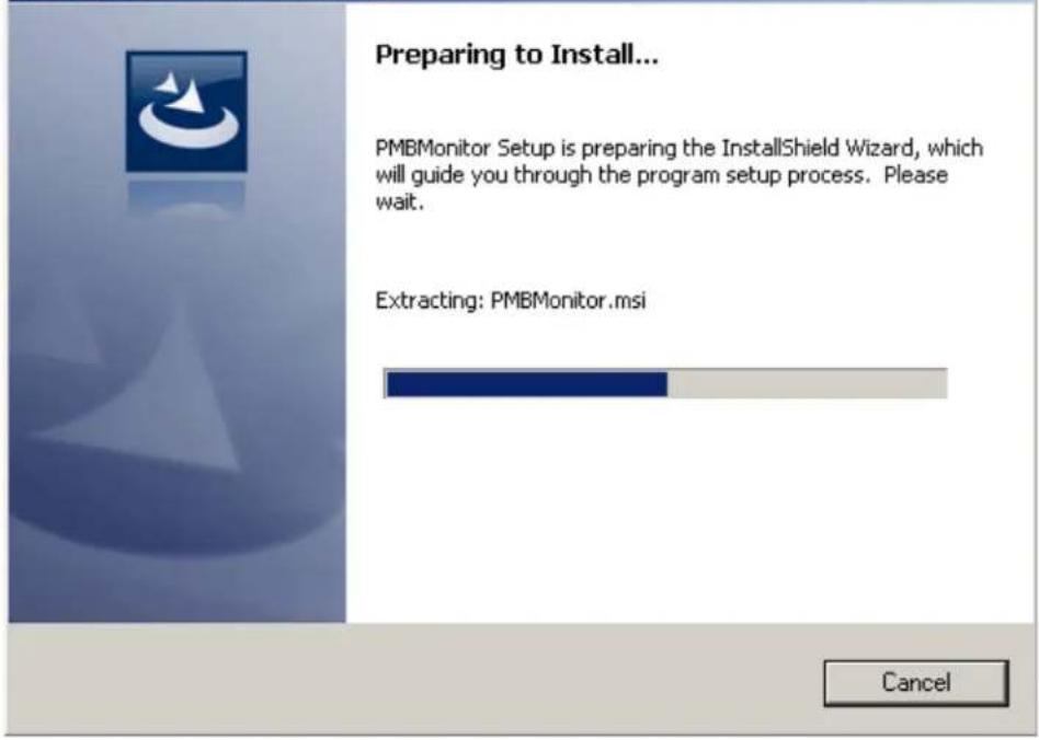
text_image
Preparing to Install... PMBMonitor Setup is preparing the InstallShield Wizard, which will guide you through the program setup process. Please wait. Extracting: PMBMonitor.msi CancelFIGURE 2-1: Preparing the InstallShield Wizard for the PMBMonitor.
- In the Welcome to the InstallShield Wizard for PMBMonitor window, click on the Next button to start the installation.
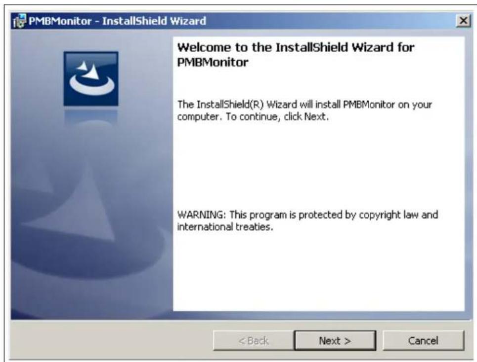
text_image
PMBMonitor - InstallShield Wizard Welcome to the InstallShield Wizard for PMBMonitor The InstallShield(R) Wizard will install PMBMonitor on your computer. To continue, click Next. WARNING: This program is protected by copyright law and international treaties. < Back Next > CancelFIGURE 2-2: Starting the PMBMonitor Installation.
- Review and accept the License Agreement by checking the I accept the terms in the license agreement option button, then click on the Next button.
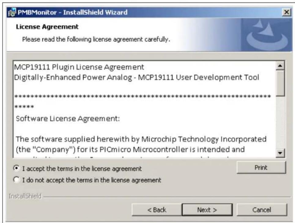
text_image
PMBMonitor - InstallShield Wizard License Agreement Please read the following license agreement carefully. MCP19111 Plugin License Agreement Digitally-Enhanced Power Analog - MCP19111 User Development Tool ************************** ***** Software License Agreement: The software supplied herewith by Microchip Technology Incorporated (the "Company") for its PICmicro Microcontroller is intended and Print I accept the terms in the license agreement I do not accept the terms in the license agreement InstallShield < Back Next > CancelFIGURE 2-3: The License Agreement Window.
- The installation path can be changed, although it is recommended to keep the default path. Click on the Next button to continue.
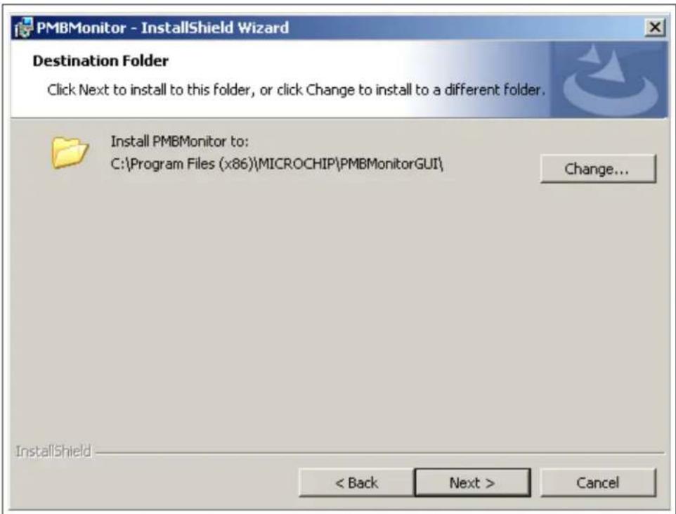
text_image
PMBMonitor - InstallShield Wizard Destination Folder Click Next to install to this folder, or click Change to install to a different folder. Install PMBMonitor to: C:\Program Files (x86)\MICROCHIP\PMBMonitorGUI\ Change... InstallShield < Back Next > CancelFIGURE 2-4: Selecting the Destination Folder.
- In the Ready to Install the Program window, click on the Install button and wait for the application to proceed with the installation. The progress can be observed in the "Status" bar.

text_image
PMBMonitor - InstallShield Wizard Ready to Install the Program The wizard is ready to begin installation. If you want to review or change any of your installation settings, click Back. Click Cancel to exit the wizard. Current Settings: Setup Type: Typical Destination Folder: C:\Program Files (x86)\MICROCHIP\PMBMonitorGUI\ User Information: Name: MicrochipTechnology Company: InstallShield < Back Install Cancel PMBMonitor - InstallShield Wizard Installing PMBMonitor The program features you selected are being installed. Please wait while the InstallShield Wizard installs PMBMonitor. This may take several minutes. Status: Creating shortcuts InstallShield < Back Next > CancelFIGURE 2-5: Installing the PMBMonitor.
- Once the installation completes, leave the Launch the program box checked to automatically start the PMBMonitor user interface or deselect this check box to start the GUI at a later stage. Click Finish to end the installation.
To start the GUI at a later stage, either click on the desktop icon or browse to Windows Start>All Programs>Microchip>PMBMonitor.

text_image
PMBMonitor - InstallShield Wizard InstallShield Wizard Completed The InstallShield Wizard has successfully installed PMBMonitor. Click Finish to exit the wizard. ✓ Launch the program < Back Finish CancelFIGURE 2-6: The Installation Complete Window.
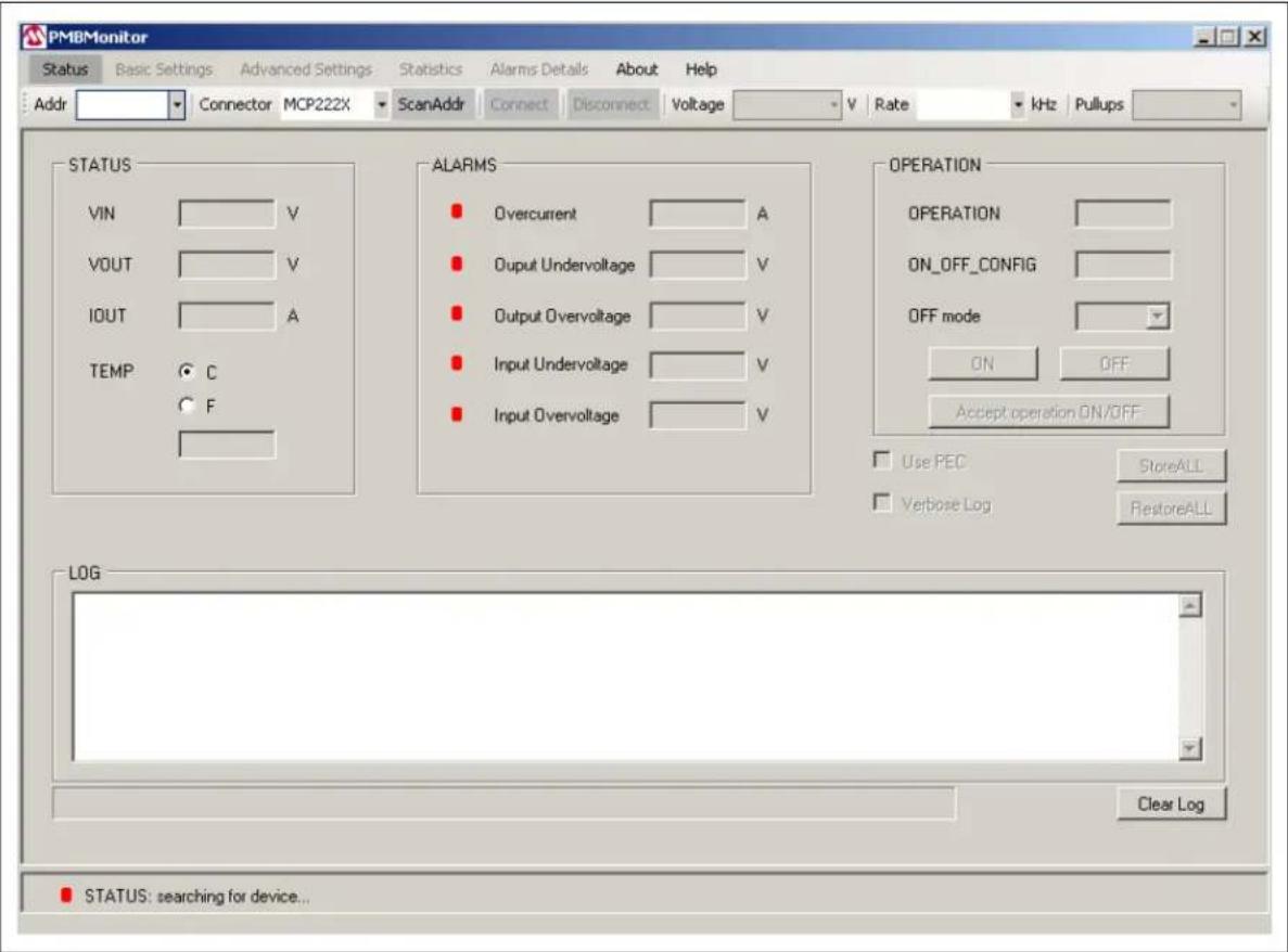
- The interface will display the Status menu and the scan address function will be active.

text_image
PMBMonitor Status Basic Settings Advanced Settings Statistics Alarm Details About Help Addr Connector MCP222X ScanAddr Canout Disconnect Voltage V Rate Hz Fullups STATUS VIN V VOUT V IOUT A TEMP C F ALARMS Overcurrent A Output Undervoltage V Output Overvoltage V Input Undervoltage V Input Overvoltage V OPERATION OPERATION ON_OFF_CONFIG OFF mode IN IP+ Accept operation ON/OFF Log PEC Verbove Log STureALL FeatureALL LOG Clear Log STATUS: searching for device...FIGURE 2-7: Initial Status Menu.
2.3 DRIVER INSTALLATION FOR THE ADAPTER
If the USB integrated on the board or a separated MCP2221 Breakout Module is used, install the appropriate driver after installing the GUI.
The following steps describe the installation process.
- Go to Windows Start>Control Panel>System and Security_. Choose System from the right panel and click Device Manager from the left pane to open the list of installed hardware. In the "Other devices" list, identify a USB unknown connection.
Right click on the unknown driver and click on "Update Driver Software".

text_image
Device Manager File Action View Help Other devices MCP2221-USB-I2C/UART Com Processors Security Devices Sound, video and game controller System devices Universal Serial Bus controllers Generic USB Hub Generic USB Hub Update Driver Software... Disable Uninstall Scan for hardware changes PropertiesFIGURE 2-8: Device Manager – Update Driver.
- In the Update Driver Software window, click on "Browse my computer for driver software" option.

text_image
Update Driver Software - MCP2221 USB-I2C/UART Combo Update Driver Software - MCP2221 USB-I2C/UART Combo How do you want to search for driver software? → Search automatically for updated driver software Windows will search your computer and the Internet for the latest driver software for your device, unless you've disabled this feature in your device installation settings. → Browse my computer for driver software Locate and install driver software manually. CancelFIGURE 2-9: Browse Computer for Driver.
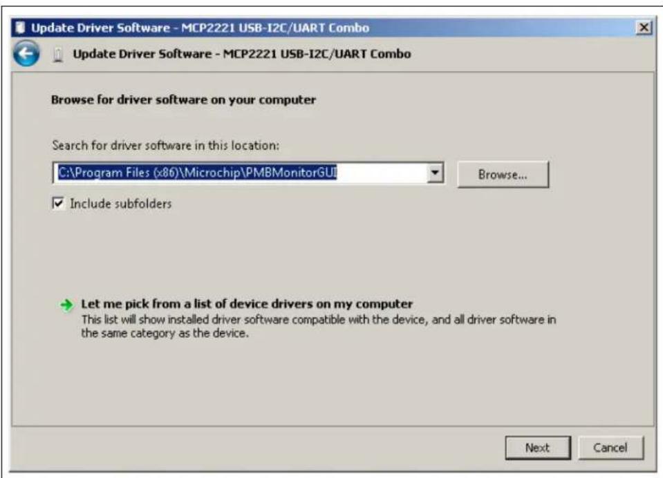
- Click on the Browse button and select the path where the GUI was installed. If the path was left unchanged, go to the
C:\Program Files (x86)\Microchip\PMBMonitorGUI folder and click the OK button.
Click Next to start the driver installation.
text_image
Update Driver Software - MCP2221 USB-I2C/UART Combo Update Driver Software - MCP2221 USB-I2C/UART Combo Browse for driver software on your computer Search for driver software in this location: C:\Program Files (x86)\Microchip\PMBMonitorGUI Browse... Include subfolders Let me pick from a list of device drivers on my computer This list will show installed driver software compatible with the device, and all driver software in the same category as the device. Next CancelFIGURE 2-10: Selecting the Path.
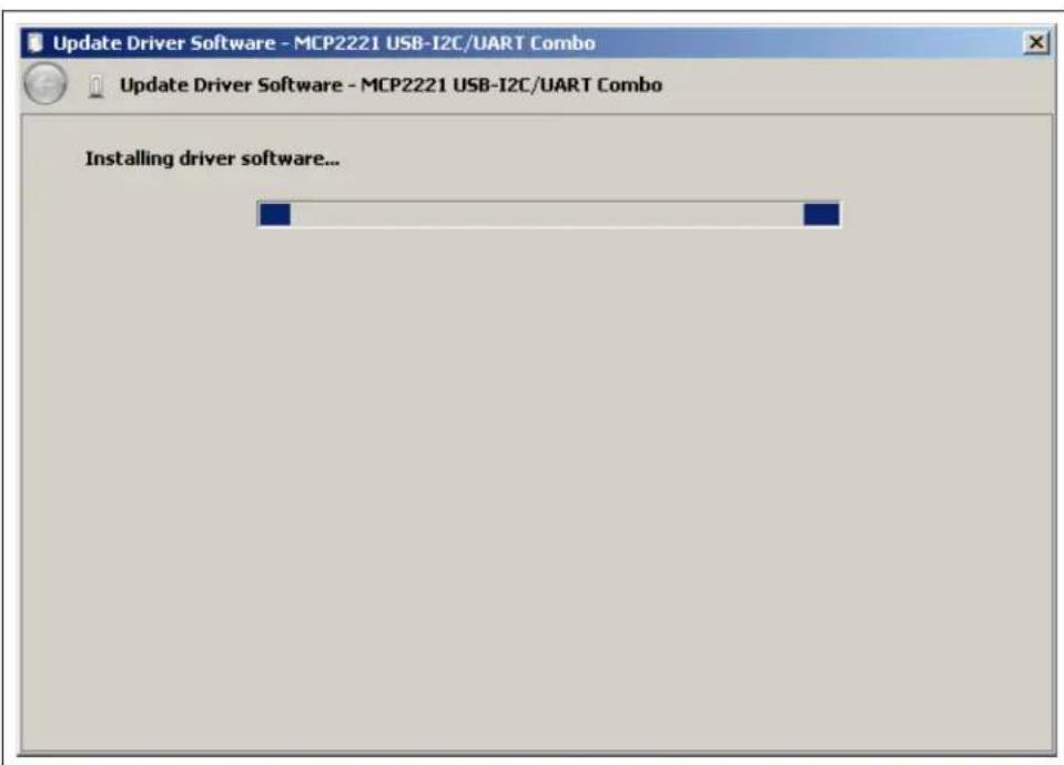
text_image
Update Driver Software - MCP2221 USB-I2C/UART Combo Update Driver Software - MCP2221 USB-I2C/UART Combo Installing driver software...FIGURE 2-11: Installing the Driver Software.
- If the following warning message pops up, select the "Install this driver anyway" option; otherwise, skip this step.

text_image
Windows Security Windows can't verify the publisher of this driver software Don't install this driver software You should check your manufacturer's website for updated driver software for your device. Install this driver software anyway Only install driver software obtained from your manufacturer's website or disc. Unsigned software from other sources may harm your computer or steal information. See detailsFIGURE 2-12: Warning Message.
If the driver was successfully installed, the following window pops up:
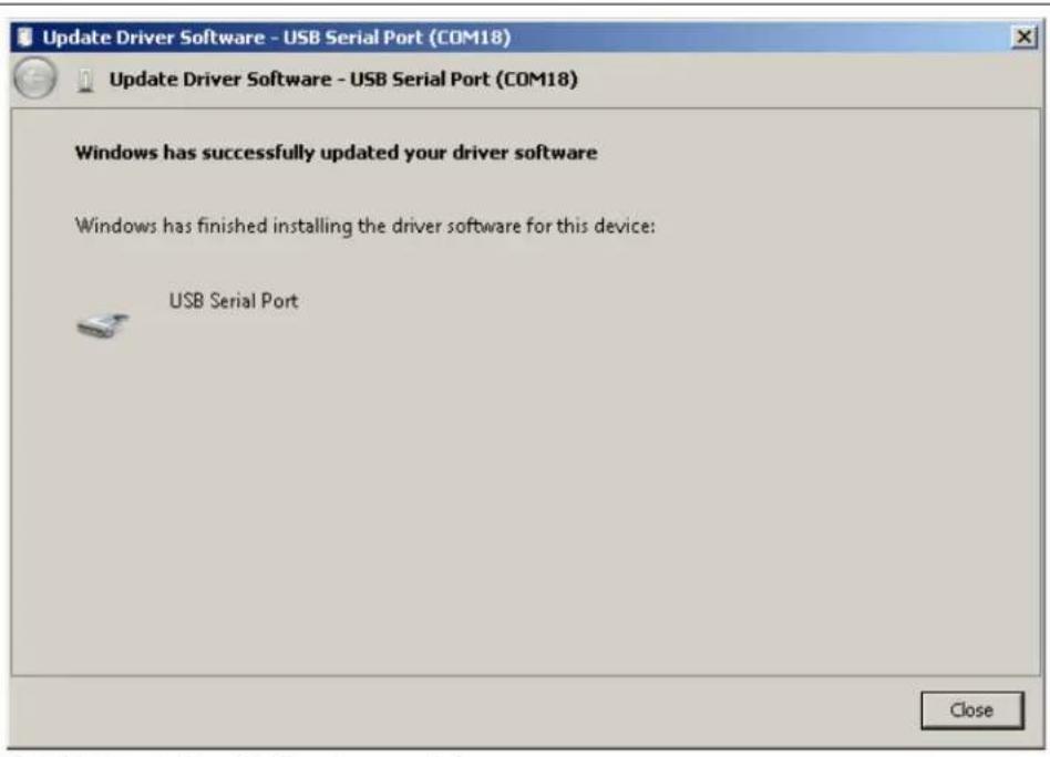
text_image
Update Driver Software - USB Serial Port (COM18) Update Driver Software - USB Serial Port (COM18) Windows has successfully updated your driver software Windows has finished installing the driver software for this device: USB Serial Port CloseFIGURE 2-13: Installation Successful.
After installation, the device should be recognized in the Device Manager; otherwise, remove and plug in the USB cable again.

FIGURE 2-14: USB Recognized.
2.4 PMBMonitor SOFTWARE UNINSTALL
In order to install the current PMBMonitor version, any previous version or corrupted version of the current one should be removed from the computer.
If there is an older version installed on the computer, the message box from Figure 2-15 will be displayed in Step 5 of the installation process. Uninstall the older version from Windows Start>Control Panel>Programs>Uninstall a Program, then go to Step 5 to resume the installation.
Windows Installer

Another version of this product is already installed. Installation of this version cannot continue. To configure or remove the existing version of this product, use Add/Remove Programs on the Control Panel.
OK
FIGURE 2-15: Windows ^® Installer Message Box.
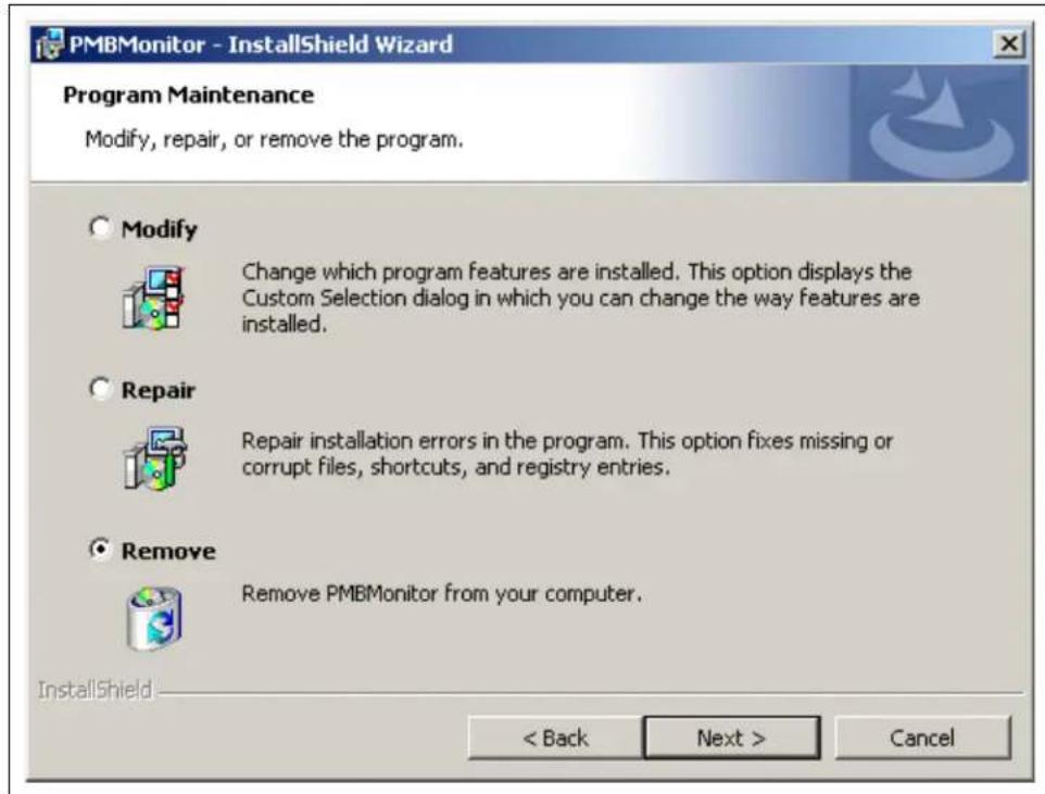
If the current PMBMonitor version is already installed on the computer, but it is corrupted, the message box in Figure 2-16 will be displayed in Step 6 of the installation process. In this case, the following steps should be followed to uninstall the current version of the PMBMonitor:
- Select the Remove option button, then click the Next button.
text_image
PMBMonitor - InstallShield Wizard Program Maintenance Modify, repair, or remove the program. Modify Change which program features are installed. This option displays the Custom Selection dialog in which you can change the way features are installed. Repair Repair installation errors in the program. This option fixes missing or corrupt files, shortcuts, and registry entries. Remove Remove PMBMonitor from your computer. InstallShield < Back Next > CancelFIGURE 2-16: The Program Maintenance Window.
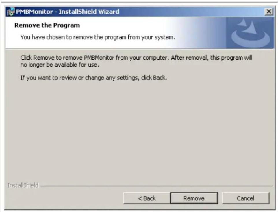
- In the Remove the Program window, click the Remove button to remove the current PMBMonitor version from the computer.
text_image
PMBMonitor - InstallShield Wizard Remove the Program You have chosen to remove the program from your system. Click Remove to remove PMBMonitor from your computer. After removal, this program will no longer be available for use. If you want to review or change any settings, click Back. InstallShield < Back Remove CancelFIGURE 2-17: Removing Previous Installations.
- When the PMBMonitor completes the uninstall process, click on the Finish button, then go to Step 5 to resume the installation of the PMBMonitor GUI.

text_image
PMBMonitor - InstallShield Wizard Uninstalling PMBMonitor The program features you selected are being uninstalled. Please wait while the InstallShield Wizard uninstalls PMBMonitor. This may take several minutes. Status: Updating component registration InstallShield < Back Next > Cancel PMBMonitor - InstallShield Wizard InstallShield Wizard Completed The InstallShield Wizard has successfully uninstalled PMBMonitor. Click Finish to exit the wizard. < Back Finish CancelFIGURE 2-18: Uninstalling the PMBMonitor.
NOTES:
Chapter 3. Graphical User Interface Description
3.1 INTRODUCTION
This chapter describes how to use the GUI and the PMBus™ protocol device characteristics that are included and monitored.

text_image
Menu Bar PMBMonitor Status Basic Settings Advanced Settings Statistics Alarms Details About Help Addr Connector MCF222K ScanAddr Connect Disconnect Voltage V Rats kHz Pullups Connection Bar STATUS VIN V VOUT V IOLT A TEMP C F ALAFMS Overcurrent A Output Undervoltage V Output Overvoltage V Input Undervoltage V Input Overvoltage V OPERATION OPERATION ON_OFF_CONFIG OFF mode ON OFF Accept operation ON/OFF Use PEC StoreALL Vorboer Log RestoreALL LOG Text Box LOG Progress Bar Clear Log STATUS: searching for device.. Status Bar Clear Log ButtonFIGURE 3-1: Graphical User Interface – Initial Screen.
Note: If the commands are not implemented for the connected device, the "Err" message will be displayed in the corresponding fields.
3.2 THE GRAPHICAL USER INTERFACE
The following sections describe the items in the Graphical User Interface.
3.2.1 Menu Bar
The menu bar contains the items available for the user to display the device's characteristics and settings, as shown in Table3-1.
| Status | Basic Settings | Advanced Settings | Statistics | Alarms Details | About | Help | Developer |
FIGURE 3-2: Menu Bar.
TABLE 3-1: MENU BAR ITEMS
| Item Description | |
| Status Displays the Status menu. | |
| Basic Settings Displays the Basic Settings menu. | |
| Advanced Settings Displays the Advanced Settings menu. | |
| Statistics Displays the Statistics menu. | |
| Alarms Details Displays the Alarms Details menu. | |
| About | Shows information about the version of the product. |
| Help | Opens a PDF document with details on the PMBusTM Monitoring Graphical User Interface. |
| Developer | Displays the Developer menu. This menu is only available for Microchip PMBus protocol-enabled devices. |
3.2.2 Connection Bar
The connection bar contains the items in Table 3-2.

text_image
Addr Connector MCP222X ScanAddr Connect Disconnect Voltage V Rate kHz PullupsFIGURE 3-3: Connection Bar.
TABLE 3-2: CONNECTION BAR ITEMS
| Item | Description |
| Addr | This drop-down menu shows the address of the PMBusTM protocol device. |
| Connector | This drop-down menu shows the type of connector used to connect the board to the PC. The connector is automatically recognized. Connect the MCP19111 board to the PC by connecting a PICkitTM Serial Analyzer (PICkitSA) to the connector on the board. Alternatively, connect to the PC using the USB port on the MCP19111 board. In this case, the MCP222X integrated in the MCP19111 board is used to perform the communication. |
| ScanAddr | This button is used to scan for PMBus protocol devices connected to the PC. |
| Connect/Disconnect | These buttons are used to connect/disconnect the PMBus protocol device. (Note 1) |
| Voltage | This drop-down menu is used to select the voltage level of the I^2C communication interface. (Note 2) |
| Rate | This drop-down menu is used to select the corresponding communication rate for the device. |
| Pullups | This drop-down menu is only available when the PICkitSA connector is used and allows enabling/disabling the PICkit pull-ups. |
Note 1: The Disconnect button is disabled when the ScanAddr and Connect buttons are enabled, and enabled when the ScanAddr and Connect buttons are disabled.
2: When using the MCP2221 Breakout Module, the voltage can be set by hardware (the jumpers on the board).
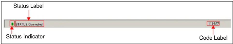
3.2.3 Status Bar
The status bar provides information on the status of the device connected to the PC. This bar is available in all menus.
text_image
Status Label STATUS: Connected! 111-667 Status Indicator Code LabelFIGURE 3-4: The Status Bar.
The items available in the status bar are shown in Table 3-3.
TABLE 3-3: STATUS BAR ITEMS
| Item Description | |
| Status Indicator | The status indicator turns red if there is no device connected to the PC. Otherwise, this indicator turns green. |
| Status Label T | The status label on the bottom of the GUI shows if there is any device connected to the board. Refer to Table 3-4 for a list of the possible labels. |
| Code Label If | an MCP19111 board is connected, this label shows the firmware version. For devices that do not implement this specific command, this label shows “N/A:N/A”. |
TABLE 3-4: STATUS LABELS
| Status Label Description | |
| STATUS: searching for device... | This message is shown when opening the GUI, before scanning the address of the device. |
| STATUS: Connected! | This message is shown when the GUI detects a device connected to the board. |
| STATUS: Disconnected! | This message is shown when the GUI does not detect any device connected to the board. |
3.2.4 LOG Text Box
This text box is used to display messages from the PMBus communication. It is updated after each command and it gathers all information if the "Verbose Log" check box in the Status menu is selected, and until the Clear Log button is pressed. If the "Verbose Log" check box is not selected, the "LOG" text box will be updated only after the values have been sent on the PMBus protocol and the parameter values have been written.
The LOG text box is available in the Status, Basic Settings, Advanced Settings, Statistics and Developer menus.
3.2.5 Clear Log Button
This button deletes all messages shown in the "LOG" text box, up to the time when the button has been pressed.
The Clear Log button is available in the Status, Basic Settings, Advanced Settings, Statistics and Developer menus.
3.2.6 Status Menu
The Status menu is the first tab displayed when opening the PMBMonitor.
text_image
PMBMonitor Status Basic Settings Advanced Settings Statistics Alarms Details About Help Addr Connector MCP222X ScanAddr Connect Disconnect Voltage V Rate kHz Pullups STATUS VIN V VOUT V IOUT A TEMP C F ALARMS Overcurrent A Output Undervoltage V Output Overvoltage V Input Undervoltage V Input Overvoltage V OPERATION OPERATION ON_OFF_CONFIG OFF mode ON OFF Accept operation ON/OFF Use PEC StartALL Verbose Log RestoreALL LOG Clear Log STATUS: searching for device...FIGURE 3-5: Initial Status Menu.
The Status menu is only used to monitor the PMBus device parameters, to enable/disable the converter and to store/restore values. The items found in the Status menu are shown in Table 3-5.
TABLE 3-5: STATUS MENU ITEMS
| Panel Item | Description | |
| STATUS VIN | Shows the input voltage value. | |
| VOUT Shows the output voltage value. | ||
| IOUT Shows the output current value. | ||
| TEMP | Shows the temperature value. Use the C and F radio buttons to choose the type of degrees to display the temperature: Celsius or Fahrenheit. | |
| ALARMS | Overcurrent | Shows the overcurrent Fault limit. The green alarm on the left will turn red when the IOUT value is equal to or greater than the overcurrent warning/Fault limit. The overcurrent warning limit is lower than the overcurrent Fault limit. If the IOUT value is equal to or greater than the overcurrent warning/Fault limit value, the red alarm turns on and stays red until the “CLEAR FAULTS” command is sent from the Alarms Details menu. |
| Output Undervoltage | Shows the output undervoltage Fault limit. The green alarm on the left will turn red when the VOUT value is lower than or equal to the output undervoltage warning/Fault limit. The output undervoltage warning limit is greater than the output undervoltage Fault limit. If the VOUT value is lower than or equal to the output undervoltage warning/Fault limit, the red alarm turns on and stays on until the “CLEAR FAULTS” command is sent from the Alarms Details menu. | |
| Output Overvoltage | Shows the output overvoltage Fault limit. The green alarm on the left will turn red when the VOUT value is equal to or greater than the output overvoltage warning/Fault limit. The output overvoltage warning limit is lower than the output overvoltage Fault limit. If the VOUT value is equal to or greater than the overvoltage output warning/Fault limit, the red alarm turns on and stays on until the “CLEAR FAULTS” command is sent from the Alarms Details menu. | |
| Input Undervoltage | Shows the input undervoltage Fault limit. The green alarm on the left will turn red when the VIN value is lower than or equal to the input undervoltage warning/Fault limit. The input undervoltage warning limit is greater than the input undervoltage Fault limit. If the VIN value is lower than or equal to the input undervoltage warning/Fault limit, the red alarm turns on and stays on until the “CLEAR FAULTS” command is sent from the Alarms Details menu. | |
| Input Overvoltage | Shows the input overvoltage Fault limit. The green alarm on the left will turn red when the VIN value is equal to or greater than the input overvoltage warning/Fault limit. The input overvoltage warning limit is lower than the input overvoltage Fault limit. If the VIN value is equal to or greater than the input overvoltage warning/Fault limit, the red alarm turns on and stays on until the “CLEAR FAULTS” command is sent from the Alarms Details menu. | |
| Panel Item Description | ||
| OPERATION | OPERATION | This box is filled in with the operation command value. If the Most Significant bit (MSb) is '1', the converter is enabled; otherwise, the converter is disabled. |
| ON_OFF_CONFIG | This box is filled in with the ON_OFF_CONFIG command value. The converter is initially disabled and can be enabled using the operation PMBus command. | |
| OFF mode | This drop-down menu allows the user to choose whether the converter will be turned off with the delay set in the Advanced Settings menu or with no delay. | |
| ON/OFF These buttons are used to enable/disable the converter. | ||
| Accept operation ON/OFF | This button is used to modify the ON_OFF_CONFIG value so that the PMBus device accepts the ON/OFF operation. | |
| Use PEC The PMBus stack supports communication with or without a Packet Error Checking (PEC) byte. (1) This check box is used to communicate the supporting PEC byte. | ||
| StoreALL This button stores the values in the Flash (nonvolatile) memory. | ||
| Verbose Log | This check box is used to activate or deactivate the log from the "LOG" text box. When checked, the log is written in the "LOG" text box for all the menus (including Status, Basic Settings, Advanced Settings, Statistics and Developer). | |
| RestoreALL | This button restores values from the Flash memory. Before restoring, press the OFF button to stop the board from switching. | |
| Progress Bar | The progress bar completes after scanning for the PMBus devices process or when the PMBus devices process has finished. | |
Note 1: An extra byte. after the standard number of bytes specified by the command. is considered a PEC byte.
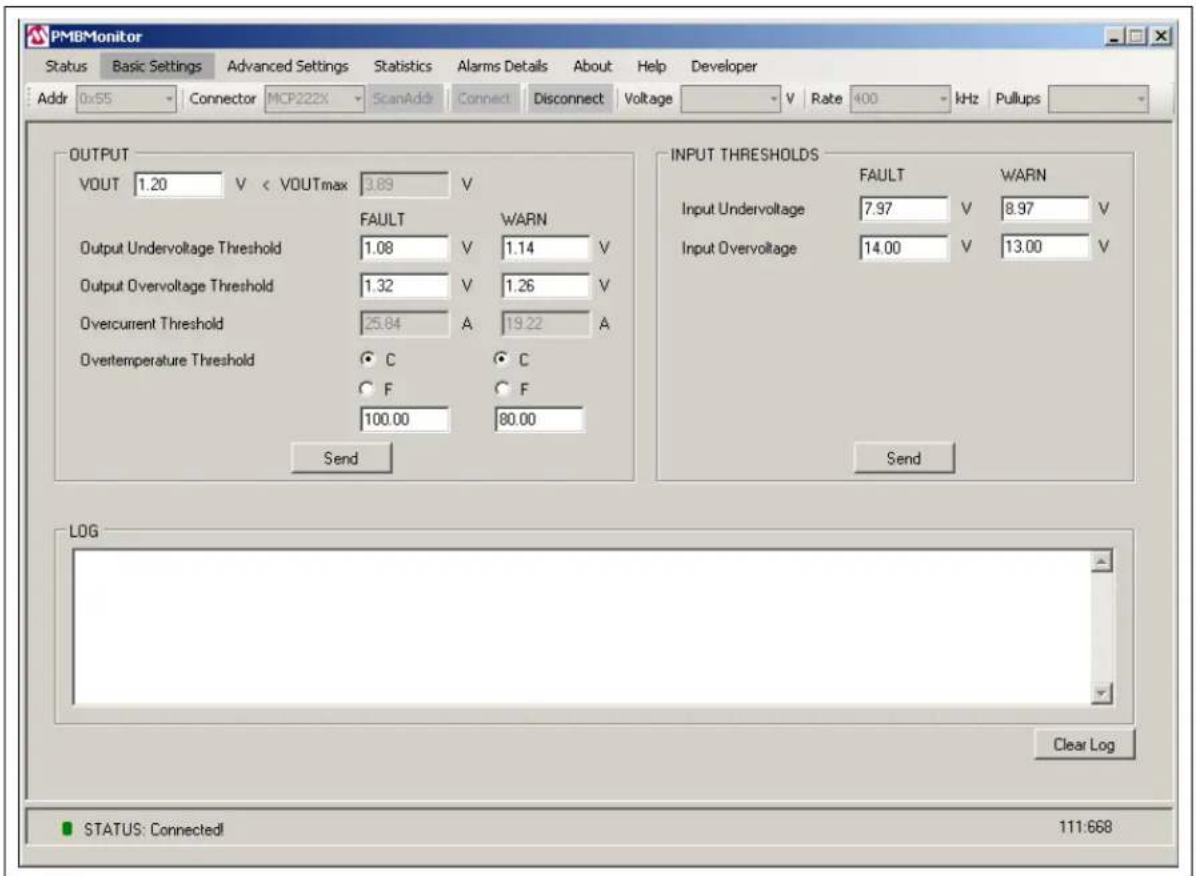
3.2.7 Basic Settings Menu
The Basic Settings menu allows changing the VOUT value, the output undervoltage threshold and output overvoltage threshold warning/Fault limit, the input undervoltage and input overvoltage warning/Fault limit, and the overtemperature threshold. The overcurrent threshold warning/Fault limit and VOUTmax value cannot be changed.
text_image
PMBMonitor Status Basic Settings Advanced Settings Statistics Alarms Details About Help Developer Addr 0x55 Connector MCP222X ScanAdds Connect Disconnect Voltage V Rate 400 kHz Pullups OUTPUT VOUT 1.20 V < VOUTmax 3.89 V FAULT WARN Output Undervoltage Threshold 1.08 V 1.14 V Output Overvoltage Threshold 1.32 V 1.26 V Overcurrent Threshold 25.84 A 19.22 A Overtemperature Threshold C C F F 100.00 80.00 Send INPUT THRESHOLDS FAULT WARN Input Undervoltage 7.97 V 8.97 V Input Overvoltage 14.00 V 13.00 V Send LOG STATUS: Connected! 111:668FIGURE 3-6: The Basic Settings Menu.
The items found in the Basic Settings menu are shown in Table 3-6.
TABLE 3-6: BASIC SETTINGS MENU ITEMS
| Panel Item | Description | |
| OUTPUT VOUT | Shows the last updated value sent | on the PMBusTM to the device. |
| VOUTmax Shows the maximum output voltage value. | ||
| Output Undervoltage Threshold(1) | Shows the output undervoltage limit value. | |
| Output Overvoltage Threshold(1) | Shows the output overvoltage limit value. | |
| Overcurrent Threshold(1) | Shows the overcurrent limit value. | |
| Overtemperature Threshold(1) | Shows the overtemperature limit value. | |
| FAULT(2) | Shows the corresponding Fault limit value for the output undervoltage/output overvoltage/overcurrent/overtemperature. | |
| WARN(2) | Shows the corresponding warning limit value for the output undervoltage/output overvoltage/overcurrent/overtemperature. | |
| C/F These radio buttons allow choosing the type of degrees used to display the temperature: Celsius or Fahrenheit. | ||
| Send This button is used to send the above parameters to the PMBus. | ||
| INPUT THRESHOLDS | Input Undervoltage Shows the input undervoltage limit value. | |
| Input Overvoltage Shows the input overvoltage limit value. | ||
| FAULT(2) | Shows the corresponding Fault limit value for the input undervoltage/input overvoltage. | |
| WARN(2) | Shows the corresponding warning limit value for the input undervoltage/input overvoltage. | |
| Send This button is used to send the above parameters to the PMBus. | ||
Note 1: For the overvoltage, overcurrent and overtemperature thresholds, the FAULT value must be greater than the WARN value. For the undervoltage threshold, the FAULT value must be smaller than the WARN value.
2: Usually, the FAULT and WARN values for one threshold must be changed simultaneously. If one threshold remains unchanged, it could raise unexpected alarms.
3.2.8 Advanced Settings Menu
The Advanced Settings menu is used to change the maximum output voltage (VOUTmax), the output voltage related parameters (POWER_GOOD_ON, POWER_GOOD_OFF, TON_RISE, TOFF_FALL) and the switching frequency (SWITCHING_FREQUENCY).
WARNING
Use caution when changing certain parameters, such as SWITCHING_FREQUENCY, because it may affect the hardware functionality. Make sure a correct value is filled in as there is no verification mechanism.

text_image
PMBMonitor Status Basic Settings Advanced Settings Statistics Alarms Details About Help Developer Addr 0x55 Connector MGP222X ScanAddr Connect Disconnect Voltage V Rate 400 kHz Pullups ADVANCED VOUTmax 3.89 V IOUTmax 25.84 A PMBusAddress 0x 65 Send VOUT POWER_GOOD_ON 1.15 V POWER_GOOD_OFF 1.10 V TON_RISE 32.00 ms TOFF_FALL 32.00 ms Send FREQUENCY SWITCHING_FREQUENCY 571.00 kHz Send LOG Clear Log STATUS: Connected! 111:668FIGURE 3-7: The Advanced Settings Menu.
The items found in the Advanced Settings menu are shown in Table 3-7.
TABLE 3-7: ADVANCED SETTINGS MENU ITEMS
| Panel Item | Description | |
| ADVANCED VOUT | IOUTmax Shows the maximum output voltage value in Volts. | |
| IOUTmax Shows the overcurrent Fault limit in Amperes. | ||
| PMBusAddress Shows the address of the PMBusTM protocol-enabled device. | ||
| Send This button is used to send the information set in the ADVANCED panel to the PMBus. | ||
| VOUT POWER_GOOD_ON Sets the output voltage at which an optional POWER_GOOD signal should be asserted. | ||
Note 1: Depending on the revision of the board, the "FREQUENCY" group box will not be included in the Advanced Settings menu.
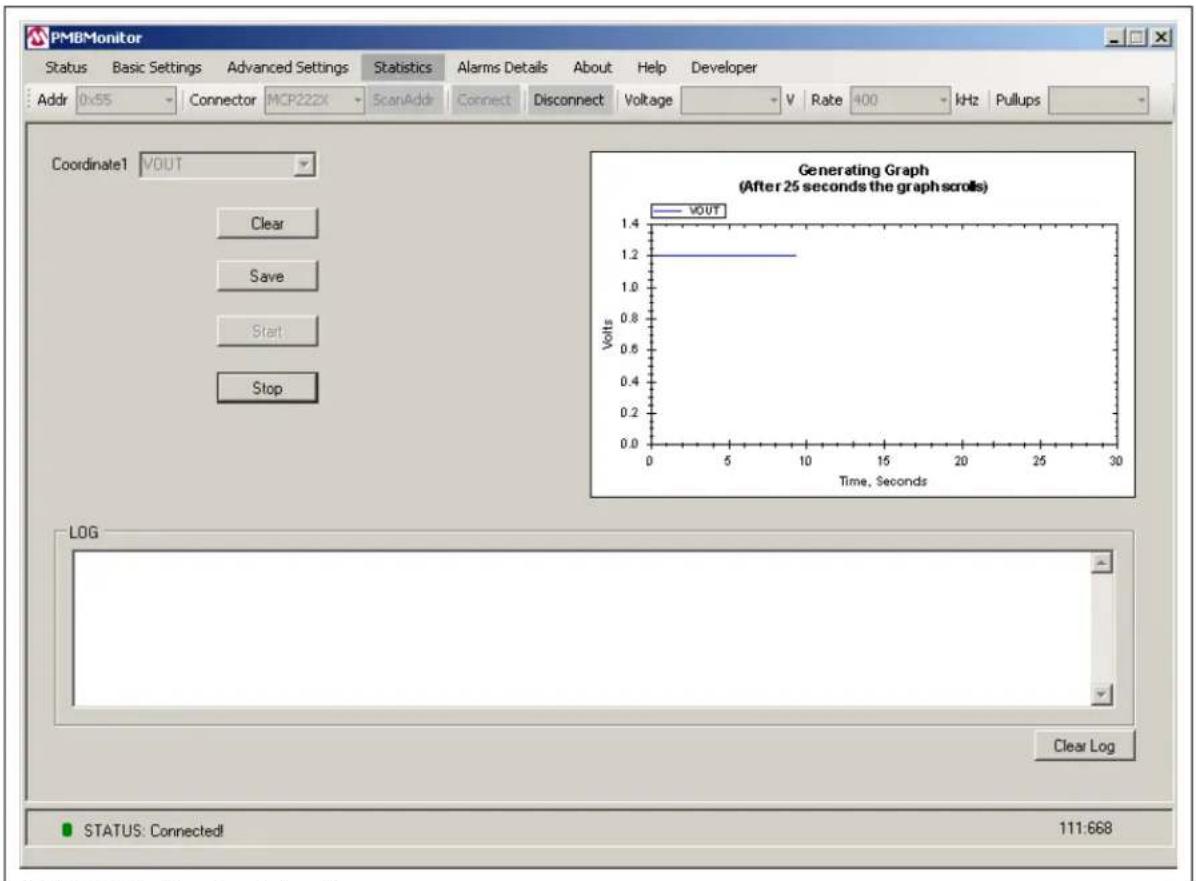
3.2.9 Statistics Menu
The Statistics menu provides an overview of the output voltage (VOUT), input voltage (VIN), output current (IOUT) and temperature (TEMP) values over time.
text_image
PMBMonitor Status Basic Settings Advanced Settings Statistics Alarms Details About Help Developer Addr 0x55 Connector MCP222X ScanAddr Connect Disconnect Voltage V Rate 400 kHz Pullups Coordinate1 VOUT Clear Save Start Stop Generating Graph (After 25 seconds the graph scrolls) VOUT Volts 0 5 10 15 20 25 30 Time, Seconds LOG Clear Log STATUS: Connected! 111:668FIGURE 3-8: The Statistics Menu.
The items found in the Statistics menu are shown in Table 3-8.
TABLE 3-8: STATISTICS MENU ITEMS
| Item Description | |
| Coordinate1 Use this selection box to choose the characteristic to monitor: VOUT, VIN, IOUT, TEMP. | |
| Clear Use this button to clear the graph. | |
| Save Use this button to save the current image of the graph. | |
| Start | Use this button to start monitoring the chosen characteristic and to start generating the graph. |
| Stop Use this button to stop scrolling the graph and to stop generating the graph. | |
| Graph Area This area displays the graph created while monitoring the chosen characteristic. | |
3.2.10 Alarms Details Menu
The Alarms Details menu presents the following status indicators: STATUS_WORD, STATUS_VOUT, STATUS_IOUT, STATUS_INPUT, STATUS_TEMPERAURE, STATUS_CML. Green means the corresponding parameters function properly, while red means a warning, a Fault or an error has occurred.

text_image
PMBMonitor Status Basic Settings Advanced Settings Statistics Alarms Details About Help Developer Addr 0x55 Connector MCP222X ScanAddr Connect Disconnect Voltage V Rate 400 kHz Pullups ALARMS STATUS_WORD L ●Busy ●OFF ●Overvoltage ●Overcurrent ●Undervoltage ●Temperature CML ●Other H ●VOUT ●IOUT ●INPUT MFR ●POWER_GOOD FANS ●Other ●Unknown STATUS_VOUT ○OVFault ○OVWam ○UVWam ○UVFault ○VOUT_MAXWam TON_MAXFault ○TOFF_MAXFault ●ErrorTrack STATUS_IOUT ○OCFault ○CLowVoltage ○CWam ○UCFault ○CurrentShareF ○PowerLimiting POUT_OPFault POUT_OVWam STATUS_INPUT ○OVFault ○OVWam ○UVWam ○UVFault ○OFF_Insufficient IIN_OCFault IIN_OCWam PIN_OVWam STATUS_TEMPERATURE ○OTFault ○OTWam ○UTWam ○UTFault ○Reserved ○Reserved ○Reserved STATUS_CML ○InvalidCmd ○InvalidData ○PEC_Failed MemFault ○ProcessorFault ○Reserved ○OtherCommFaults ○OtherMemFaults READ FAULTS CLEAR FAULTS STATUS: Connected! 111:668FIGURE 3-9: The Alarms Details Menu.
The items found in the Alarms Details menu are shown in Table 3-9.
TABLE 3-9: ALARMS DETAILS MENU ITEMS
| Item Description | |
| STATUS_WORD Combines all other status indicators and resumes Faults and warnings. | |
| STATUS_VOUT Displays warnings, Faults and other errors regarding the output voltage values. | |
| STATUS_IOUT Displays warnings, Faults and other errors regarding the output current. | |
| STATUS_INPUT Displays warnings, Faults and other errors regarding the input characteristics. | |
| STATUS_TEMPERATURE | Displays warnings and Faults regarding temperature. |
| STATUS_CML | Displays warnings, Faults and other errors regarding communication. |
| READ FAULTS | Reads and updates/refreshes the alarms. |
| CLEAR FAULTS Clears all these indicators and turns them to green. | |
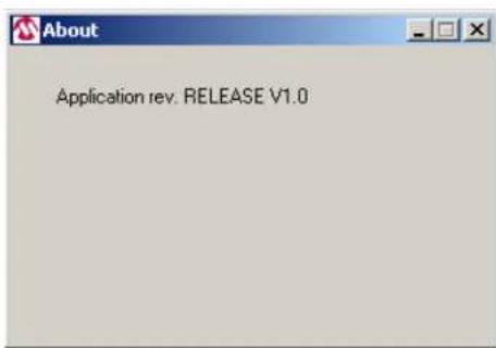
3.2.11 About Menu
The About menu includes the PMBMonitor version number.
text_image
Application rev. RELEASE V1.0FIGURE 3-10: The About Menu.
3.2.12 Help Menu
The Help menu opens the current user's guide in PDF format.
3.2.13 Developer Menu
The Developer menu consists of two tabs: Settings and Calibration.
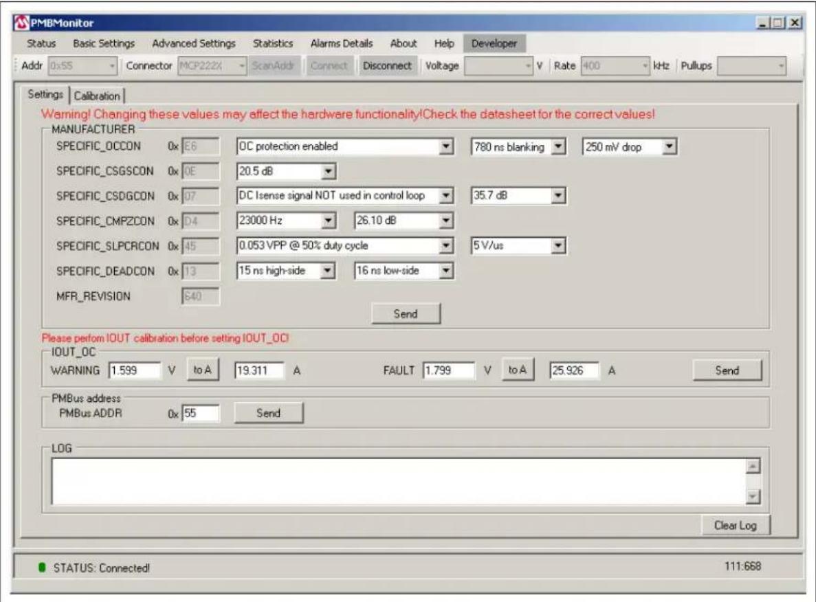
3.2.13.1 SETTINGS TAB
The Settings tab allows changing some manufacturer compensation values and setting the overcurrent limit.
WARNING
Check the values before clicking on the Send button; new values can affect hardware functionality. Make sure to read and understand the hardware specifics. The Settings tab is available only for Microchip devices. This step uses only custom commands, manufacturer-specific, and these commands are functional with the specific Microchip firmware. For more information, read the material listed under Recommended Reading.
text_image
PMBMonitor Status Basic Settings Advanced Settings Statistics Alarms Details About Help Developer Addr 0x55 Connector MCP222X ScanAddr Connect Disconnect Voltage V Rate 400-kHz Pullups Settings Calibration Warning! Changing these values may affect the hardware functionality!Check the datasheet for the correct values! MANUFACTURER SPECIFIC_OCCON 0x:E6 0C protection enabled 780 ns blanking 250 mV drop SPECIFIC_CSGSCON 0x:OE 20.5 dB SPECIFIC_CSDGCON 0x:07 DC Isense signal NOT used in control loop 35.7 dB SPECIFIC_CMPZCON 0x:D4 23000 Hz 26.10 dB SPECIFIC_SLPCRCON 0x:45 0.053 VPP @ 50% duty cycle 5 V/us SPECIFIC_DEADCON 0x:13 15 ns high-side 16 ns low-side MFR_REVISION 640 Send Please perform IOUT calibration before setting IOUT_OC IOUT_OC WARNING 1.599 V[to A 19.311 A FAULT 1.799 V[to A 25.926 A Send PMBus address PMBus ADDR 0x:55 Send LOG STATUS: Connected! 111:668FIGURE 3-11: The Settings Tab.
The items found in the Settings tab are shown in Table 3-10.
TABLE 3-10: SETTINGS TAB ITEMS
| Group Box Item Description | ||
| MANUFACTURER | SPECIFIC_OCCON | This register controls the voltage drop across the high-side MOSFET to determine when an output overcurrent exists. |
| SPECIFIC_CSGSCON This register controls the amount of gain amplified by the current sense AC gain circuitry. | ||
| SPECIFIC_CSDGCON This register controls the amount of DC gain added to the sensed inductor current to allow it to be read. | ||
| SPECIFIC_CMPZCON This register is used to adjust the compensation zero frequency and gain. | ||
| SPECIFIC_SLPCRCON This register controls the amount of slope added to the error amplifier output signal before it is compared to the current sense signal. | ||
| SPECIFIC_DEADCON This register controls the adjustment of the driver dead time. | ||
| MFR_REVISION Shows the revision of the PMBusTM protocol-enabled device. | ||
| Send Use this button to send the specific commands to the PMBus. | ||
| IOUT_OC WARNING | Shows the overcurrent warning limit value. The value in Volts comes from the ADC. | |
| to A | These buttons transform the voltage in the overcurrent warning/Fault value from Volts (coming from ADC) to the corresponding values in Amperes using the specific compensation equation. | |
| FAULT | Shows the overcurrent Fault limit value. The value in Volts comes from the ADC. | |
| Send Use this button to send the overcurrent warning and Fault limit to the PMBus. | ||
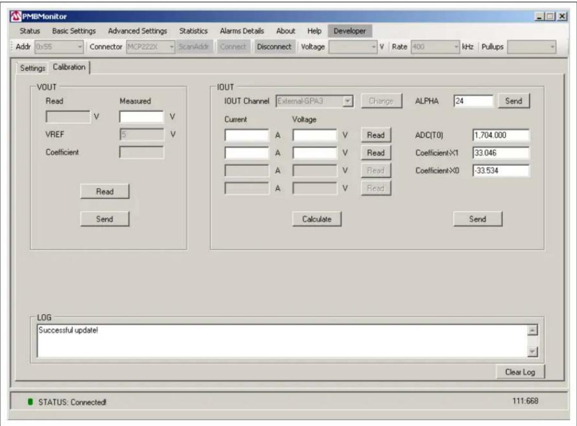
3.2.13.2 CALIBRATION TAB
The Calibration tab allows calibrating the reading/settings of the output voltage and the output current.
text_image
PMBMonitor Status Basic Settings Advanced Settings Statistics Alarms Details About Help Developer Addr 0x55 Connector MCP222X ScanAddr Connect Disconnect Voltage V Rate 400 kHz Pullups Settings Calibration VOUT Read Measured V V V VREF 5 V Coefficient Read Send IOUT IOUT Channel External:GPA3 Change ALPHA 24 Send Current Voltage A V Reading ADC(T0) 1.704.000 A V Read Coefficient×1 33.046 A V Read Coefficient×0 -33.534 A V Read Calculate Send LOG Successful update! Clear Log STATUS: Connected! 111.668FIGURE 3-12: The Calibration Tab – Firmware Version 668.
The items found in the Calibration tab are shown in Table 3-11.
TABLE 3-11: CALIBRATION TAB ITEMS
| Group Box | Item Description | |
| VOUT Read | Shows the output voltage value read from the PMBusTM in Volts. | |
| Measured Shows the measured output voltage value in Volts. | ||
| VREF Shows the reference for ADC. | ||
| Coefficient Represents the correction to the VOUT value. | ||
| Read Use this button to read the VOUT “Read” value. | ||
| Send Use this button to send the correction coefficient to the PMBus. | ||
| IOUT IOUT Channel Sets the internal or external channel to measure the output current. | ||
Note 1: When ADC(T0) is present, the Coefficient-X2 label is not present. In fact, ADC(T0) appears instead of Coefficient-X2 and Coefficient-X2 appears instead of ADC(T0), depending on the firmware version.
For the 667 and 668 firmware revisions, "ADC(T0)" replaces the "Coefficient-X2" field, and the last two lines from the "Current" and "Voltage" columns are disabled.
Calibration will be done only in two points, taking into consideration the temperature.
For the 666 revision, "ADC(T0)" is replaced by "Coefficient-X2".
WARNING
The calibration is hardware-specific and is related to Microchip devices. Do not calibrate unless you carefully read the documentation.
NOTES:
Chapter 4. Using the PMBus Graphical User Interface
WARNING
Make sure you are familiar with the PMBus™ protocol before starting to use the GUI. If this is the first use of the board, a compensation/calibration procedure might be required. Severe malfunction of the board can occur if these steps are skipped. Read the board user guide before starting to use the GUI.
To perform the communication between the board and the PC, follow these steps:
- Connect the board to the PC, using either a PICkit™ Serial Analyzer to be connected to the I²C connector, or the MCP2221 Breakout Module. The connector is automatically detected by the interface. The board connected to the PC may already include the MCP2221 Breakout Module. For these devices, just plug the USB cable into the USB connector.
- Select the "400" option from the Rate drop-down menu. If the "Connector" field shows "PICkitSA", also select the "5" option from the Voltage drop-down menu and the "enabled" option from the Pullups drop-down menu.

text_image
Addr 0x55 Connector PBOISA ScanAddr Connect Disconnect Voltage 5 Rate 400 kHz Pullups enabled Select "5" Select "400" Select "enabled"FIGURE 4-1: Connection Bar.
- Press on the ScanAddr button. If the board is connected, the address will be shown in the Addr drop-down menu. If there are several addresses, manually select the correct address of the board from the list of available addresses (0x55 for the MCP19111 board). Then, press the Connect button for the communication to start running.
Note: If "PICkitSA" is selected in the Connector drop-down menu, do not press on the ScanAddr button several times in a row. Unplug and replug the PICKit Serial Analyzer, then press the ScanAddr button.
The same behavior occurs on pressing the Disconnect button, followed by pressing the Connect button. If "PICKitSA" is selected, unplug and then plug the connector again after pressing the Disconnect button, and before pressing the Connect button.
No restrictions apply if MCP222X is selected in the Connector drop-down menu.
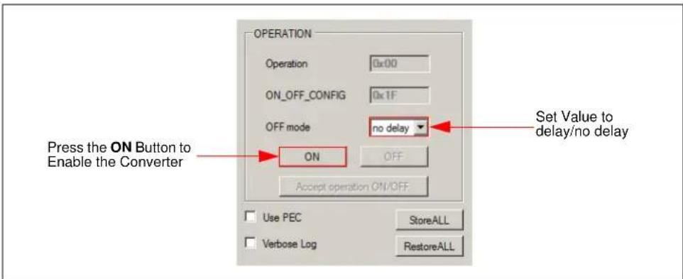
- In the Status menu, under the OPERATION panel, press the ON button to enable the converter. If the converter does not start and an alarm is triggered (the red button on the left of a threshold), check the Alarms Details menu, identify and solve the issues before retrying to start the converter. To enable the converter, it might be necessary to set the output voltage in the Basic Settings menu to a greater or lower value. If the output overvoltage, undervoltage or overcurrent Fault limit has been reached, the converter turns off automatically and it can be powered on again only after the alarms triggered have been resolved.
text_image
OPERATION Operation 0x00 ON_OFF_CONFIG 0x1F OFF mode no delay Press the ON Button to Enable the Converter ON OFF Accept operation ON/OFF Set Value to delay/no delay Use PEC StoreALL Verbose Log RestoreALLFIGURE 4-2: Status Menu – OPERATION Panel.
- From the drop-down menu, set the "OFF mode" parameter to turn off the converter with or without delay. If the "delay" option is chosen, the converter will stop with a TOFF_FALL delay, set in the Advanced Settings menu.
- Depending on the user's preferences, the following options can be selected:
- Choose between the C and F radio buttons for the temperature to be displayed in either Celsius or Fahrenheit degrees.
- Select the "Use PEC" check box if the communication must support the PEC byte.
- To close the communication between the GUI and the board, press the Disconnect button from the Connection bar, then resume from Step 1.
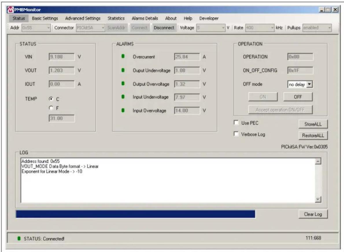
Note: If "PICkitSA" is selected in the Connector drop-down menu, a label with the PICkit Serial Analyzer firmware version will be displayed under the RestoreALL button, as shown in Figure 4-3.
text_image
PMBMonitor Status Basic Settings Advanced Settings Statistics Alarms Details About Help Developer Addr 0x55 Connector PICKITA ScanAddr Connect Disconnect Voltage 5 V Rate 400 kHz Pullups enabled STATUS VIN 9.188 V VOUT 1.203 V IOUT 0.00 A TEMP C F 31.00 ALARMS Overcurrent 25.84 A Output Undervoltage 1.08 V Output Overvoltage 1.32 V Input Undervoltage 7.97 V Input Overvoltage 14.00 V OPERATION OPERATION 0x80 ON_OFF_CONFIG 0x1F OFF mode=no delay ON OFF Accept operation ON/OFF. Use PEC.StoreALL Verbose Log RestoreALL LOG Address found: 0x55 VOUT_MODE Data Byte format -> Linear Exponent for Linear Mode -> -10 Clear Log STATUS: Connected! 111:668FIGURE 4-3: Status Menu – PICkit™ Serial Analyzer Connected.
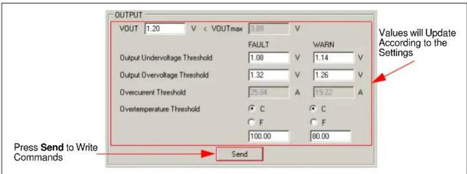
- In the Basic Settings menu, press the Send button in the OUTPUT panel to write the commands (values) included on the PMBus stack. Then, the values of the parameters for all the thresholds will be replaced with the values entered in the text boxes. The value from the "VOUT" box is the voltage set or the value that was sent via the PMBus stack on the last update. If VOUT has never been changed, the default value will be displayed in the "VOUT" box.
text_image
OUTPUT VOUT 1.20 V < VOUTmax 3.89 V FAULT WARN Output Undervoltage Threshold 1.08 V 1.14 V Output Overvoltage Threshold 1.32 V 1.26 V Overcurrent Threshold 25.64 A 19.22 A Overtemperature Threshold C C F F 100.00 80.00 Press Send to Write Commands Send Values will Update According to the SettingsFIGURE 4-4: Basic Settings Menu – OUTPUT Panel.
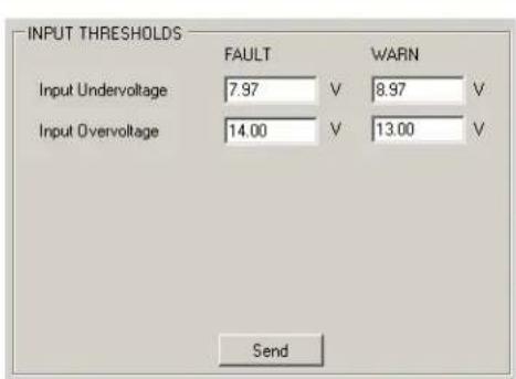
- Press Send in the INPUT THRESHOLDS panel to write the commands (values) included in this panel on the PMBus stack.
text_image
INPUT THRESHOLDS FAULT WARN Input Undervoltage 7.97 V 8.97 V Input Overvoltage 14.00 V 13.00 V SendFIGURE 4-5: Basic Settings Menu – INPUT THRESHOLDS Panel.
-
In the Advanced Settings menu, change any parameter, as applicable, and click the Send button from the corresponding panel with the changed data.
-
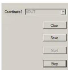
In the Statistics menu (Figure 4-6), select one of the options in the "Coordinate1" selection box to display the corresponding graph. The following options are available:
- When clicking the Start button, the time coordinate will be displayed on the X axis in seconds and the selected coordinate will be displayed on the Y axis using the corresponding measurement unit.
Note: The Start button will be disabled until the Stop or Clear buttons are pressed.
- Clicking the Save button will allow capturing the current image of the graph.
- Clicking the Stop or Clear button will allow selecting another coordinate for generating the graph.
Note: While the graph is generated, the Read buttons from the Calibration tab in the Developer menu are disabled. Click the Stop or Clear button to stop scrolling the graph and to enable the Read buttons in the Calibration tab.
text_image
Coordinate1 VOUT Clear Save Start Stop
line
| Time, Seconds | VOLT | | ------------- | ---- | | 0 | 1.2 | | 10 | 1.2 | | 20 | 1.2 | | 30 | 1.2 |FIGURE 4-6: Statistics Menu.
- Check the Alarms Details menu to see if the green icon on the left of each bit has turned red. The red icon indicates that a warning, a Fault or an error has occurred. If the icon on the left of any bit is red, identify and solve the cause of the alarm.
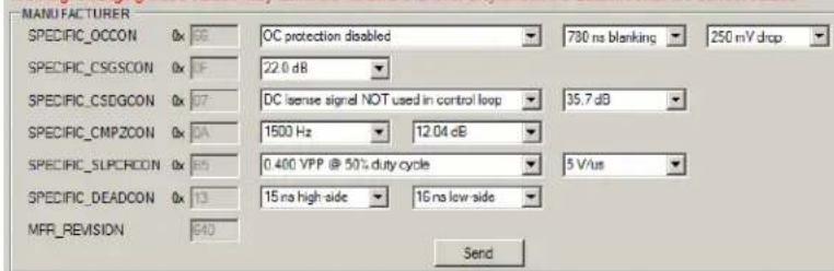
- Go to the Settings tab in the Developer menu. Under the MANUFACTURER panel, set the specific values (SPECIFIC_OCCON, SPECIFIC_CSGSCON, SPECIFIC_CSDGCON, SPECIFIC_CMPZCON, SPECIFIC_SLPCRCON, SPECIFIC_DEADCON).
Click Send to transmit these values to the PMBus.
WARNING
It is recommended to read the "MCP19110/11 Data Sheet" (DS20002331) and the "TB3139, MCP19111 PMBus™ Firmware Technical Brief" (DS90003139) before changing any values in the MANUFACTURER panel.
Warning! Changing these values may affect the hardware functionality! Check the datasheet for the correct values!
text_image
MANUFACTURER SPECIFIC_OCCON 0x 58 OC protection disabled 730 ns blanking 250 mV drop SPECIFIC_CSGSCON 0x 1F 22.0 dB SPECIFIC_CSDGCON 0x 07 DC license signal NOT used in control loop 35.7 dB SPECIFIC_CMPZCON 0x 0A 1500 Hz 12.04 dB SPECIFIC_SLPCRON 0x 65 0.400 VPP @ 50% duty cycle 5 V/us SPECIFIC_DEADCON 0x 13 15 na high-side 16 na low-side MFR_REVISION 640 SendFIGURE 4-7: Settings Tab – MANUFACTURER Panel.
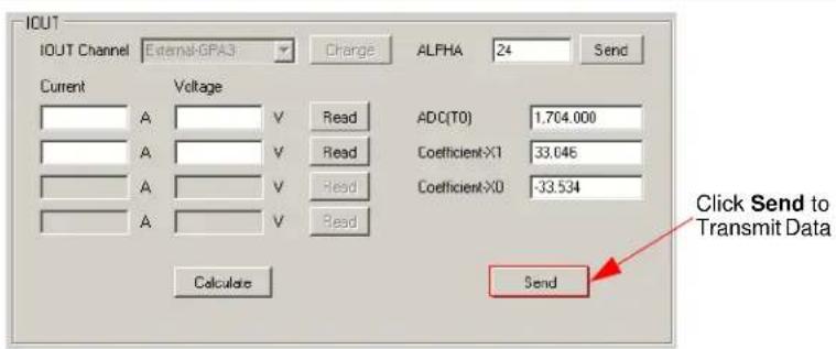
-
Before setting the overcurrent warning and Fault values, go to the Calibration tab and type the current values in the Current column in the IOUT panel. Perform the following tasks:
-
Click the Read button corresponding to the current value for which the measurement has been performed.
- Set all points for IOUT calibration, then click on the Calculate button.
- Click the Send button at the bottom of the IOUT panel to transmit the values to the PMBus.
text_image
IOUT IOUT Channel External-GPA3 Charge ALFHA 24 Send Current Voltage ADC(T0) 1,704.000 A V Read Coefficient-X1 33.046 A V Read Coefficient-X0 -33.534 A V Read Calculate Send Click Send to Transmit DataFIGURE 4-8: Calibration Tab – IOUT Panel.
For a better understanding and usage of calibration procedure, refer to the "MCP19111 PMBus™ Protocol-Enabled Point-of-Load (POL) Converter Reference Design User's Guide" (DS50002379) document.
- To set the overcurrent warning limit and Fault, return to the Settings tab and type the current values in the WARNING and FAULT fields corresponding to the Volt values in the IOUT_OC panel. Click the to A button to have a value on the left field in Volts, filled in by the user, and a calculated value in the right field in Amperes.
Click the Send button in the IOUT_OC panel to transmit the values to the PMBus.

text_image
IOUT_CC WARNING 1.636 V to A 18.994 A FAULT 1.796 V to A 20.991 A SendFIGURE 4-9: Settings Tab - IOUT_OC Panel.
-
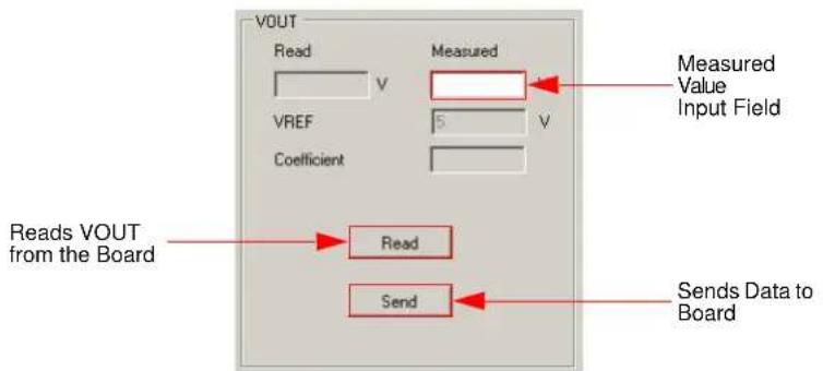
Go to the Calibration tab under the Developer menu to calibrate VOUT. Perform the following tasks:
-
Click the Read button in the VOUT panel.
- Measure the real VOUT and type the value in the "Measured" field.
- Click the Send button in the VOUT panel to write calibration values for VOUT.
text_image
VOUT Read V Measured VREF 5 V Coefficient Read Send Data to Board Reads VOUT from the BoardFIGURE 4-10: Calibration Tab - VOUT Panel.
Note: For the 667 and 668 firmware revision boards, the current can be calibrated only in two points, and taken into consideration a temperature coefficient instead of a second-order coefficient, and four calibration points for the 666 firmware revision. The procedure is basically the same as above, except that it is necessary to wait for the temperature equilibrium to be reached.
- The device calibration is now complete. Click the StoreALL button in the Status menu to retain the values after the device has been powered off, or on the RestoreALL button to return to the default values.
- Disconnect the board from the PC to end the communication.
Worldwide Sales and Service
AMERICAS
Corporate Office
2355 West Chandler Blvd.
Chandler, AZ 85224-6199
Tel: 480-792-7200
Fax: 480-792-7277
Technical Support:
http://www.microchip.com/
support
Web Address:
www.microchip.com
Atlanta
Duluth, GA
Tel: 678-957-9614
Fax: 678-957-1455
Austin, TX
Tel: 512-257-3370
Boston
Westborough, MA
Tel: 774-760-0087
Fax: 774-760-0088
Chicago
Itasca, IL
Tel: 630-285-0071
Fax: 630-285-0075
Cleveland
Independence, OH
Tel: 216-447-0464
Fax: 216-447-0643
Dallas
Addison, TX
Tel: 972-818-7423
Fax: 972-818-2924
Detroit
Novi, M
Tel: 248-848-4000
Houston, TX
Tel: 281-894-5983
Indianapolis
Noblesville, IN
Tel: 317-773-8323
Fax: 317-773-5453
Los Angeles
Mission Viejo, CA
Tel: 949-462-9523
Fax: 949-462-9608
New York, NY
Tel: 631-435-6000
San Jose, CA
Tel: 408-735-9110
Canada - Toronto
Tel: 905-673-0699
Fax: 905-673-6509
ASIA/PACIFIC
Asia Pacific Office
Suites 3707-14, 37th Floor
Tower 6, The Gateway
Harbour City, Kowloon
Hong Kong
Tel: 852-2943-5100
Fax: 852-2401-3431
Australia - Sydney
Tel: 61-2-9868-6733
Fax: 61-2-9868-6755
China - Beijing
Tel: 86-10-8569-7000
Fax: 86-10-8528-2104
China - Chengdu
Tel: 86-28-8665-5511
Fax: 86-28-8665-7889
China - Chongqing
Tel: 86-23-8980-9588
Fax: 86-23-8980-9500
China - Dongguan
Tel: 86-769-8702-9880
China - Hangzhou
Tel: 86-571-8792-8115
Fax: 86-571-8792-8116
China - Hong Kong SAR
Tel: 852-2943-5100
Fax: 852-2401-3431
China - Nanjing
Tel: 86-25-8473-2460
Fax: 86-25-8473-2470
China - Qingdao
Tel: 86-532-8502-7355
Fax: 86-532-8502-7205
China - Shanghai
Tel: 86-21-5407-5533
Fax: 86-21-5407-5066
China - Shenyang
Tel: 86-24-2334-2829
Fax: 86-24-2334-2393
China - Shenzhen
Tel: 86-755-8864-2200
Fax: 86-755-8203-1760
China - Wuhan
Tel: 86-27-5980-5300
Fax: 86-27-5980-5118
China - Xian
Tel: 86-29-8833-7252
Fax: 86-29-8833-7256
ASIA/PACIFIC
China - Xiamen
Tel: 86-592-2388138
Fax: 86-592-2388130
China - Zhuhai
Tel: 86-756-3210040
Fax: 86-756-3210049
India - Bangalore
Tel: 91-80-3090-4444
Fax: 91-80-3090-4123
India - New Delhi
Tel: 91-11-4160-8631
Fax: 91-11-4160-8632
India - Pune
Tel: 91-20-3019-1500
Japan - Osaka
Tel: 81-6-6152-7160
Fax: 81-6-6152-9310
Japan - Tokyo
Tel: 81-3-6880-3770
Fax: 81-3-6880-3771
Korea - Daegu
Tel: 82-53-744-4301
Fax: 82-53-744-4302
Korea - Seoul
Tel: 82-2-554-7200
Fax: 82-2-558-5932 or
82-2-558-5934
Malaysia - Kuala Lumpur
Tel: 60-3-6201-9857
Fax: 60-3-6201-9859
Malaysia - Penang
Tel: 60-4-227-8870
Fax: 60-4-227-4068
Philippines - Manila
Tel: 63-2-634-9065
Fax: 63-2-634-9069
Singapore
Tel: 65-6334-8870
Fax: 65-6334-8850
Taiwan - Hsin Chu
Tel: 886-3-5778-366
Fax: 886-3-5770-955
Taiwan - Kaohsiung
Tel: 886-7-213-7828
Taiwan - Taipei
Tel: 886-2-2508-8600
Fax: 886-2-2508-0102
Thailand - Bangkok
Tel: 66-2-694-1351
Fax: 66-2-694-1350
EUROPE
Austria - Wels
Tel: 43-7242-2244-39
Fax: 43-7242-2244-393
Denmark - Copenhagen
Tel: 45-4450-2828
Fax: 45-4485-2829
France - Paris
Tel: 33-1-69-53-63-20
Fax: 33-1-69-30-90-79
Germany - Dusseldorf
Tel: 49-2129-3766400
Germany - Karlsruhe
Tel: 49-721-625370
Germany - Munich
Tel: 49-89-627-144-0
Fax: 49-89-627-144-44
Italy - Milan
Tel: 39-0331-742611
Fax: 39-0331-466781
Italy - Venice
Tel: 39-049-7625286
Netherlands - Drunen
Tel: 31-416-690399
Fax: 31-416-690340
Poland - Warsaw
Tel: 48-22-3325737
Spain - Madrid
Tel: 34-91-708-08-90
Fax: 34-91-708-08-91
Sweden - Stockholm
Tel: 46-8-5090-4654
UK - Wokingham
Tel: 44-118-921-5800
Fax: 44-118-921-5820