MIC45205 - Electronic component Microchip - Free user manual and instructions
Find the device manual for free MIC45205 Microchip in PDF.

User questions about MIC45205 Microchip
0 question about this device. Answer the ones you know or ask your own.
Ask a new question about this device
Download the instructions for your Electronic component in PDF format for free! Find your manual MIC45205 - Microchip and take your electronic device back in hand. On this page are published all the documents necessary for the use of your device. MIC45205 by Microchip.
USER MANUAL MIC45205 Microchip
This application note describes two methods for updating the software on the Soc 2-MII Board and its predecessor – the Soc Test Board. The two boards are essentially identical, and this document refers to them both as the "SoC board".
Table 1. SoC Board Identification
| Ordering Part Number | Silkscreen Label on Board |
| KSZ9692-MII-PTP-EV | Soc 2-MII BOARD |
| KSZ9692PB-PTP-EVAL Soc Test BOARD | |
The SoC board is intended to be used with the KSZ8463, KSZ8462 and KSZ8441 Eval Boards, which have the following ordering part numbers:
KSZ8463MLI-EVAL
KSZ8462HLI-EVAL
KSZ8441HLI-EVAL
The KSZ84xx family of devices has hardware features to support the IEEE 1588 Precision Time Protocol (PTP) standard, and the SoC board comes installed with Linux, KSZ84xx drivers, and one or more stacks that implement the IEEE 1588 protocol.
From time to time Micrel may update the software image for the SoC board. Customers may choose to update the board to the latest software revision, and are especially encouraged to if their SoC board software is an early revision. Software revisions prior to the year 2013 do not fully support the production version of the KSZ84xx silicon.
natural_image
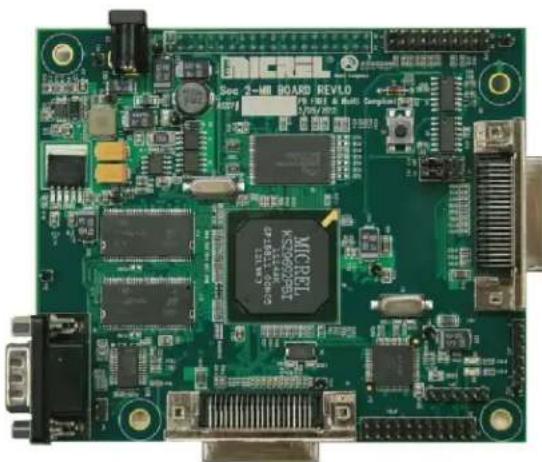
Green printed circuit board with various electronic components and connectors (no readable text or symbols)Figure 1. SoC Board
EtherSynch is a registered trademark of Micrel, Inc.
Micrel Inc. • 2180 Fortune Drive • San Jose, CA 95131 • USA • tel +1 (408) 944-0800 • fax +1 (408) 474-1000 • http://www.micrel.com
Software Revisions
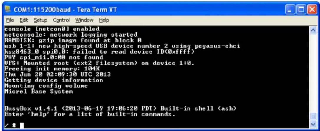
To determine the software revision that is currently installed on an SoC board, connect a serial cable between the SoC board and a PC, open a serial communication window on the PC (115,200 baud), then apply power to the SoC board. At the end of the boot-up output, look for the date. In the example displayed in Figure 2, the software date is 2013-06-19.
The most recent revision of the SoC board software image may be found on the Micrel FTP site at ftp://www.micrel.com/ethernet/8463/m92_ctrl_20130619. At the time of writing, the most recent image file is m92_ctrl_20130619. The last eight characters of the file name indicate the revision date in the format yyyymmdd. The file name does not have an extension.
text_image
COM1:115200baud - Tera Term VT File Edit Setup Control Window Help console [netcon0] enabled netconsole: network logging started RAMDISK: gzip image found at block 0 usb 1-1: new high-speed USB device number 2 using pegasus-ehci ksz8463_0 spi0.0: failed to read device ID<0xffff> PHY spi_mii.0:00 not found UFS: Mounted rootFigure 2. Software Revision Date
Choice of Methods
Two methods are available for updating the SoC board software. Table 2 summarizes the key requirements for each method. The two methods are equivalent. Users may select either one, based on which is more convenient. Once the basic setup is completed, the two methods take a similar amount of time to complete.
Table 2. Hardware and Software Requirements
| Programming Method | Hardware Requirements | Software Requirements |
| Ethernet Method | PCMicrel switch of PHY eval board[1]Ethernet cableCrossover (null-modem) serial cable[2] | TFTP utility[3]Communication utility for serial communication[4] |
| JTAG Method | PCOpenOCD compatible JTAG debugger/programmer for ARM processors[5] | OpenOCD[6] |
Notes:
- The evaluation board is needed to provide the Ethernet port to the SoC board. Typically a KSZ84xx evaluation board is used, but another switch board (e.g. KSZ8863) or PHY board (e.g. KSZ8081 or KSZ8051) may be used.
- For computers without a serial port, use a USB-to-serial converter cable, plus a separate serial crossover (null-modem) cable or adapter.
- Testing has been performed using Tftpd32.
- Examples of communication programs are TeraTerm and PuTTY.
- Several compatible programmers are made by Olimex, Tin Can Tools and many others. This example utilizes the Olimex ARM-USB-OCD.
- Users should download OpenOCD from the Micrel website. Details are given later.
Ethernet Method
IP Address on the PC
In order for the PC to communicate with the SoC board over Ethernet, they must have compatible IP addresses. The default IP address for the SoC board boot loader is 192.168.1.200, and the default server IP address is 192.168.1.11. Either the PC IP address must be changed, or the SoC board settings must be changed. Details are given below for changing the SoC board boot loader IP address.
Setup
- Install TFTP server application such as Tftpd32 on the PC.
- From the Micrel FTP server ftp://www.micrel.com/ethernet/8463, copy the SoC board software image file (e.g. m92_ctrl_20130619) to the TFTP application folder on the PC.
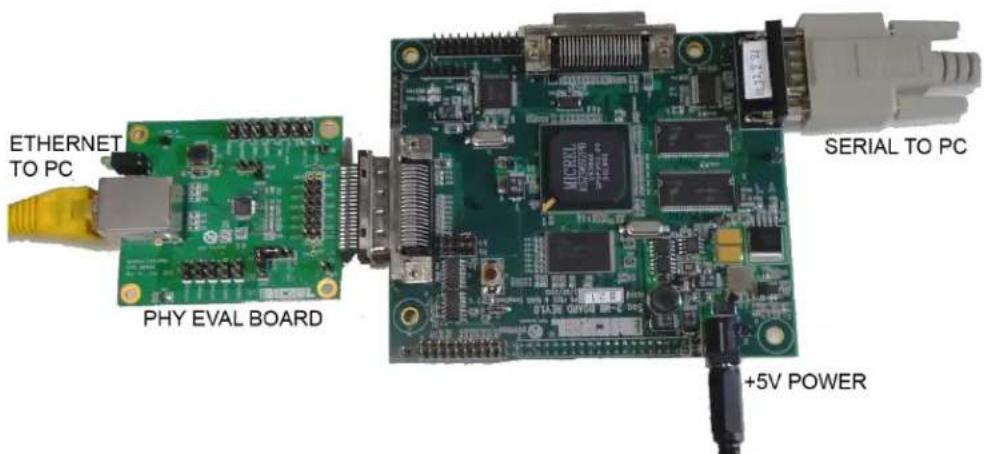
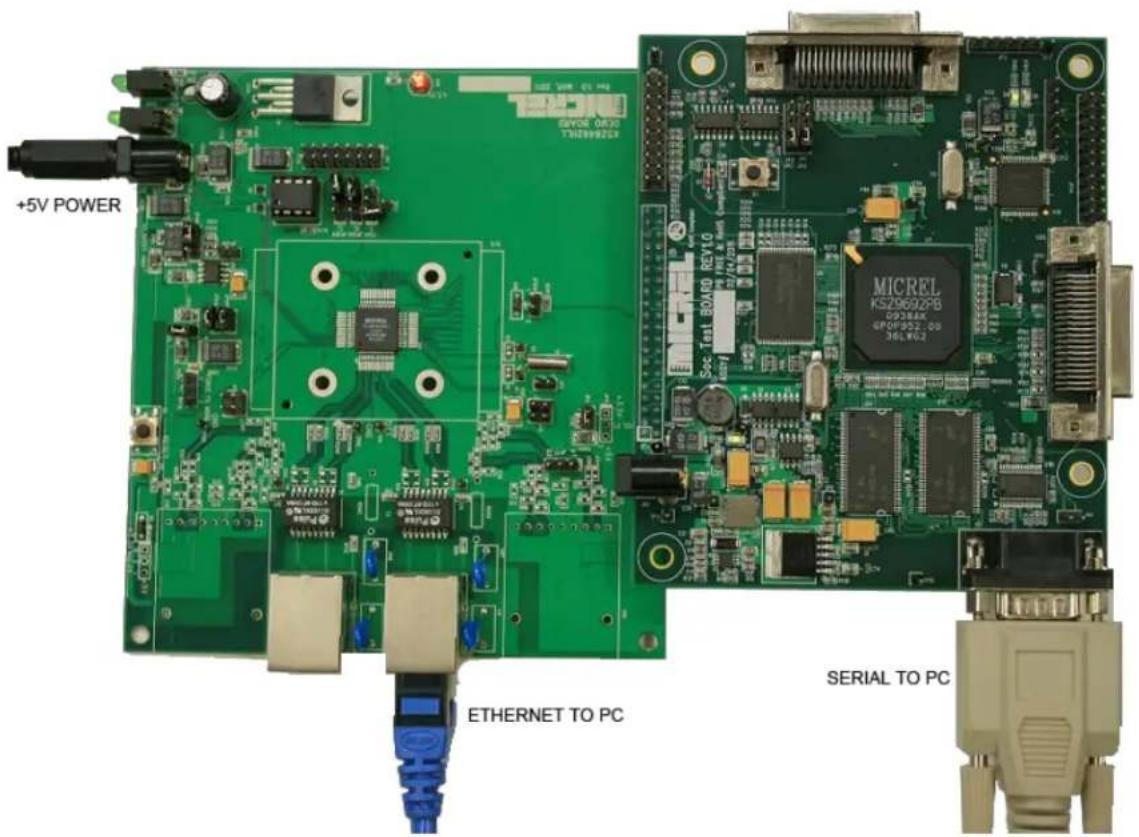
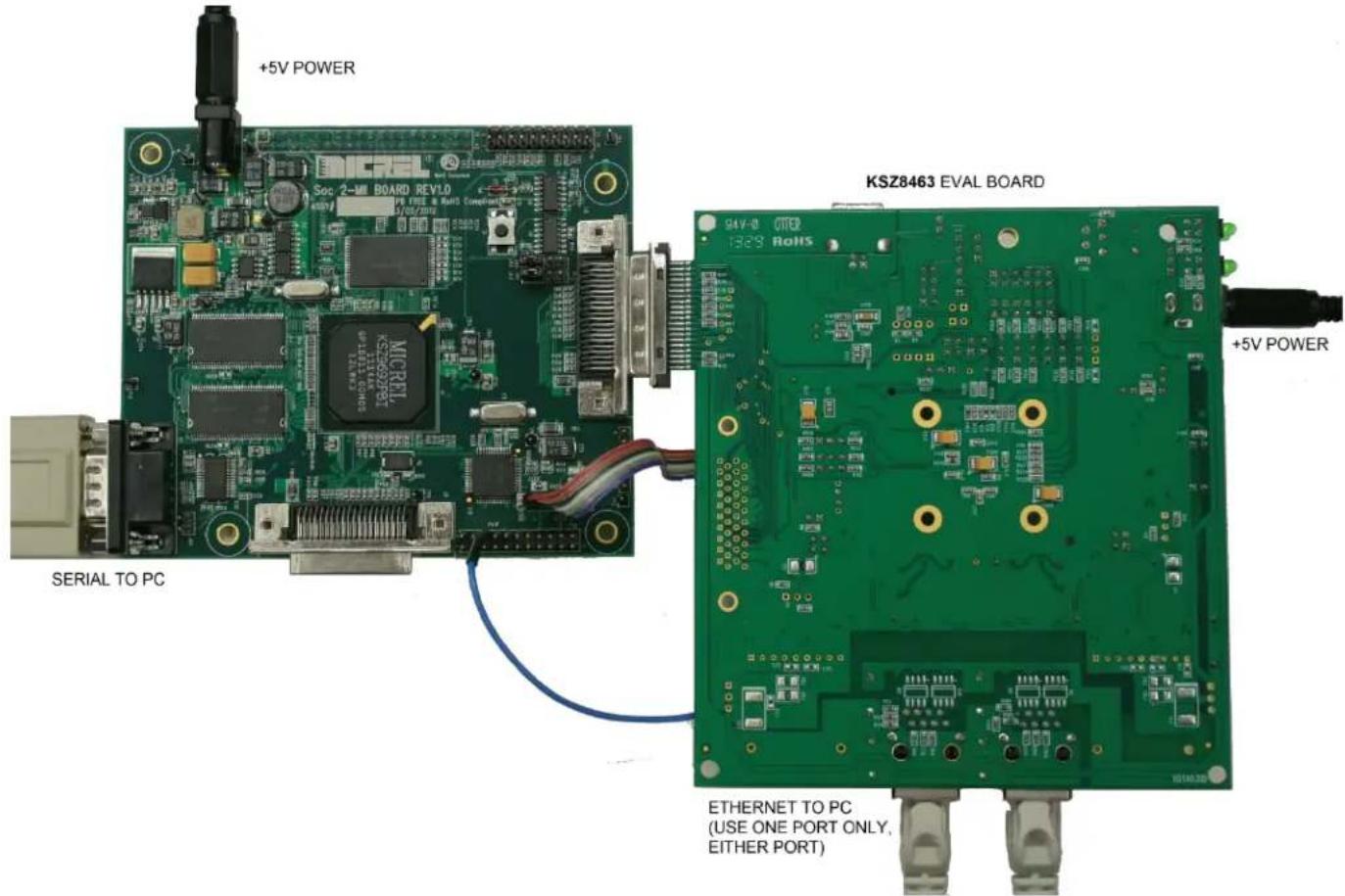
- Mate SoC board to PHY or KSZ84xx board, and power up. Figure 3, Figure 4, and Figure 5 and show examples of different but equivalent setups.
- Connect Ethernet cable between the PC and the KSZ84xx or PHY board. For a board such as the KSZ8462 or KSZ8463 board, which has two Ethernet ports, either port may be used.
- Connect serial cable between the PC and the SOC board.
text_image
ETHERNET TO PC PHY EVAL BOARD +5V POWER SERIAL TO PCFigure 3. PHY Eval Board Connected to SoC Board
text_image
+5V POWER ETHERNET TO PC SERIAL TO PC MICREL KS29692PB 0938AX GPOW052.00 3661402Figure 4. KSZ8462 Eval Board Connected to SoC Board
text_image
+5V POWER KSZ8463 EVAL BOARD +5V POWER SERIAL TO PC ETHERNET TO PC (USE ONE PORT ONLY, EITHER PORT)Figure 5. KSZ8463 Eval Board Connected to SoC Board
Programming
- Launch the TFTP server on the PC. It should indicate the IP address that it uses.
- Open a serial port communication window. The serial port settings are 115,200 baud, 8 data bits, 1 stop bit, no parity.
- Reset or reboot the SoC board.
- During the 3-second countdown at the beginning of the boot process, press any key to enter U-Boot prior to the booting of Linux. The U-boot prompt should appear as shown below:
U-Boot 1.1.4 (October 6, 2011)

DRAM: 64 MB
Flash: 1c000000 8 MB
In: serial
Out: serial
Err: serial
Hit any key to stop autoboot: 3
KSZ8462-16HLL (Lit Endian) Verification 2.0.1
Switch selftest: write\read data to 0x10 address: OK.
QMU selftest: write\read data to 0x110 address: OK.
boot >
- Ensure that the SOC board has the right IP address settings. To display the system variables, type the command "print". The response is shown below:
boot > print
bootcmd=bootm 0x1c040000
bootdelay=3
baudrate=115200
ethaddr=00:10:A1:84:62:11
ipaddr=192.168.1.200
serverip=192.168.1.11
autoload=n
netmask=255.255.255.0
stdin=serial
stdout=serial
stderr=serial
fileaddr=800000
Environment size: 212/65532 bytes
boot >
Notice the serverip value. This must match the IP address of the PC since the PC will function as the server. [Tftpd32 shows the PC's IP address.] Using the setenv command, the value of serverip can be temporarily changed. In this example, the PC is known to have the IP address 10.1.157.253:
boot > setenv serverip 10.1.157.253
Also notice the ipaddr value. This is the boot loader IP address of the SoC board, and it must be within the same address range (subnet) as that of the PC. The address range is determined by the netmask value. For
example, if it is 255.255.255.0, and the PC's IP address is 10.1.157.253, then the SoC board must have an ipaddr that is 10.1.157.xxx. Using the setenv command, the ipaddr value can be changed on the SoC board:
boot > setenv ipaddr 10.1.157.39
- Ensure that the IP addresses are properly set, using the ping command. This confirms good communication between the machines. If a different response is received, check the previous steps.
boot > ping 10.1.157.253
host 10.1.157.253 is alive
boot >
- Use TFTP to copy the image file to the SoC, then erase part of the SoC flash memory and program the new firmware.
At the serial communication window, enter the following commands. Use the correct file name of the image file.
boot > tftp 1000000 m92_ctrl_20130619
boot > prot off all
boot > erase 1c040000 1c7ffffff
To program the memory, type the following exactly as shown. Do not try to substitute a number for
“{filesize}”.
boot > cp.b 1000000 1c040000 ${filesize}
That took about 1 minute to program the memory. Now, reboot the system.
boot > reset
JTAG Method
OpenOCD software and JTAG device
Open On-Chip Debugger (OpenOCD) is an open source tool that provides access to the SoC internal resources through a JTAG interface. It supports various ARM processors, including the Micrel KSZ9692 and KSZ8692, which are substantially the same device. OpenOCD can control any of several JTAG debugger/programmers through either a parallel or (more commonly) a USB interface on the computer. The supported USB based JTAG debugger/programmer devices are all based on the FTDI FT2232 controller, which features MPSSE function. For the supported JTAG devices, check the extracted folder: openocd-0.7.0\scripts\interface\ftdi directory. In this document, an Olimex ARM-USB-OCD is used as the JTAG device.
Setup
- From the Micrel FTP server ftp://www.micrel.com/ethernet/8463, copy the SoC board software image file (e.g. m92_ctrl_20130619) to the PC. In this example, the file is copied to the following location: c:\84xx_fw\m92_ctrl_20130619
- Download and extract the OpenOCD zip file from the URL: ftp://www.micrel.com/ethernet/8692/. In this document, it is assumed that the zip file is extracted to the folder c:\openocd-0.7.0. In addition to standard release OpenOCD, this zip file includes the Micrel document Using OpenOcd 0.7.0.pdf, and a configuration file for the KSZ8692/9692. (The current revision is 0.7.0, but it may be revised in the future.)
- Check JTAG device compatibility: OpenOCD supports many JTAG debugger/programmers. A list of configuration files for supported devices is found in openocd-07.0\scripts\interface\ftdi. Make a note of the appropriate .cfg file for your programmer. This example is for the Olimex ARM-USB-OCD, but many others are supported.
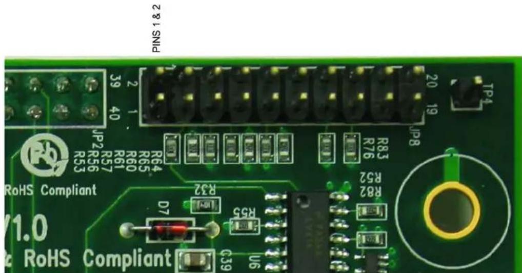
- Ensure that jumpers J42 & J43 are installed on the SoC board. Remove J40 and J41.
- Connect Olimex pod (ARM-USB-OCD) to a USB port on the computer. For first time use, Windows will open a new hardware wizard window. Refer to sections 1-3 of the Micrel document Using OpenOcd JTAG 0.7.0.pdf for details on how to properly install the USB drivers.
- Connect the ribbon cable from the Olimex pod to the 20-pin header (JP8) on the SoC board. Figure 6 shows pin 1 of JP8, which on the board is adjacent to the 40-in connector.
- Connect power to the SOC board.
text_image
PINS 1 & 2 2 & 1 SNIP JP2 R57 R61 R60 R64 R65 R53 R64 R83 R76 JP8 TP4 RoHS Compliant V1.0 RoHS Compliant D7 R32 R55 C39 U6Figure 6. Pin 1 on 20-Pin Header
Programming
- On the PC, open a command prompt window. (In Windows, type cmd in the Run box in the Start menu.)
- Start OpenOCD by typing the following in the command prompt window. When using a device other than the Olimex ARM-USB-OCD, change the first .cfg file name accordingly.
>cd c:\openocd-0.7.0
>bin\openocd-0.0.0.exe -f scripts\interface\olimex-arm-usb-ocd.cfg -f scripts\board\ks8692.cfg
It should come back with several lines of reply:
Open On-Chip Debugger 0.7.0 (2013-05-05-10:41)
Licensed under GNU GPL v2
For bug reports, read
    http://openocd.sourceforge.net/doc/doxygen/bugs.html
Info : only one transport option; autoselect 'jtag'
trst_and_srst separate srst_gates_jtag trst_push_pull srst_open_drain
...
adapter speed: 6000 kHz
fast memory access is enabled
dcc downloads are enabled
ks8692_init
Info : clock speed 6000 kHz
Info : JTAG tap: ks869x.cpu tap/device found: 0x00922f0f (mfg: 0x787, part: 0x0922, ver: 0x0)
Info : Embedded ICE version 2
Info : ks869x.cpu: hardware has 2 breakpoint/watchpoint units
- Open a second command prompt window and start a Telnet connection by typing:
telnet 127.0.0.1 4444
The following message and prompt should appear:
Open On-Chip Debugger
>
- In the Telnet window, enter the following instructions, which will erase a portion of the memory and then program it anew with the image file already on the PC hard drive. The erase command takes several seconds, and the write command may take two minutes or more.
> reset halt
> ks8692_init
> flash probe 0
> flash erase_sector 0 11 134
> flash write_image c:/84xx_fw/m92_ctrl_20130619 0x1c040000
> reset
> resume
> exit
MICREL, INC. 2180 FORTUNE DRIVE SAN JOSE, CA 95131 USA
TEL +1 (408) 944-0800 FAX +1 (408) 474-1000 WEB http://www.micrel.com
Micrel makes no representations or warranties with respect to the accuracy or completeness of the information furnished in this data sheet. This information is not intended as a warranty and Micrel does not assume responsibility for its use. Micrel reserves the right to change circuitry, specifications and descriptions at any time without notice. No license, whether express, implied, arising by estoppel or otherwise, to any intellectual property rights is granted by this document. Except as provided in Micrel's terms and conditions of sale for such products, Micrel assumes no liability whatsoever, and Micrel disclaims any express or implied warranty relating to the sale and/or use of Micrel products including liability or warranties relating to fitness for a particular purpose, merchantability, or infringement of any patent, copyright or other intellectual property right.
Micrel Products are not designed or authorized for use as components in life support appliances, devices or systems where malfunction of a product can reasonably be expected to result in personal injury. Life support devices or systems are devices or systems that (a) are intended for surgical implant into the body or (b) support or sustain life, and whose failure to perform can be reasonably expected to result in a significant injury to the user. A Purchaser's use or sale of Micrel Products for use in life support appliances, devices or systems is a Purchaser's own risk and Purchaser agrees to fully indemnify Micrel for any damages resulting from such use or sale.
© 2014 Micrel, Incorporated.