ATSAMR21E16A - Electronic component Microchip - Free user manual and instructions
Find the device manual for free ATSAMR21E16A Microchip in PDF.

User questions about ATSAMR21E16A Microchip
0 question about this device. Answer the ones you know or ask your own.
Ask a new question about this device
Download the instructions for your Electronic component in PDF format for free! Find your manual ATSAMR21E16A - Microchip and take your electronic device back in hand. On this page are published all the documents necessary for the use of your device. ATSAMR21E16A by Microchip.
USER MANUAL ATSAMR21E16A Microchip
MiWi™ Quick Start Guide
Introduction
This document describes prototyping, implementing, testing, and deploying wireless sensor networks using MiWi Protocol based on the Microchip software platform. This document also details how to get started with the MiWi by installing the development environment, setting up hardware, and programming devices with the reference applications.
Table of Contents
Introduction....1
- Overview....4
1.1. MiWi v6.3 Release Content....4
1.2. Supported Hardware Platforms and IDEs....5
-
MiWi Documentation....6
-
Development Environment Setup....7
3.1. IDE Installation....7
3.2. Stack Configurations....7
3.3. Building Applications in Atmel Studio....8
3.4. Building Applications in IAR Embedded Workbench....11
3.5. Installing the Bootloader PC Tool.... 11
3.6. Installing the WiDBG Tool....12
- Hardware Environment Setup.... 13
4.1. Supported Platforms and Boards.... 13
4.2. Additional Boards.... 15
4.3. Connections.... 15
- Simple_Example_P2P Reference Application....17
- Chat_Demo P2P Reference Application.... 23
- Simple_Example_Star Reference Application....27
- WSN Demo Mesh Reference Application....32
8.1. Launching the Demo....32
8.2. Network Startup....33
8.3. WSNMonitor....33
8.4. Identifying Nodes....35
8.5. Node Timeouts....35
8.6. Sensor Data Visualization....36
- OTAU in WSNDemo Mesh Application....38
9.1. Software Prerequisites....38
9.2. OTAU Client....38
9.3. OTAU Server....40
- Atmel WiDBG for OTAU....42
10.1. Starting the Session....42
10.2. Main Window....44
10.3. Upgrading the Node....50
- Document Revision History.... 53
The Microchip Website....54
Product Change Notification Service....54
Customer Support....54
Microchip Devices Code Protection Feature.... 54
Legal Notice....55
Trademarks.... 55
Quality Management System.... 56
Worldwide Sales and Service....57
1. Overview
MiWi Development Environment (MiWi DE) was developed by Microchip to support a wide range of wireless applications. The backbone of MiWi DE is MiMAC and MiApp interfaces, which links the support of multiple RF transceivers and wireless communication protocols together as a well-defined, simple but robust Microchip proprietary wireless development environment.
Within MiWi DE, application developers can switch between RF transceivers and wireless protocols with little or no modification in the application layer. Such migration capability in MiWi DE reduces the firmware development risk to a very minimum level. MiWi DE is defined by three layers:
- Application layer
- Protocol layer
- RF transceiver layer
The three layers are linked together by MiMAC and MiApp interfaces. The Application layer uses MiApp interfaces to communicate to the protocol layer. In the protocol layer, there are implementations of MiWi P2P, MiWi Star, and MiWi Mesh wireless communication protocols. The drivers for Microchip RF transceivers (AT86RF233, AT86RF212B) are called by protocol layers via MiMAC interfaces.
Configuration files are also presented in each layer.
Figure 1-1. MiWi™

text_image
MiWi™ Your wireless connectivity made simple.The MiWi stack offers a significantly smaller footprint relative to the open standard based ZigBee ^® compliant protocol stack. This enables operation in microcontrollers with smaller memory/lower cost.
- MiWi P2P/Star – Simple Peer-to-Peer or Star network requiring minimal code size.
- MiWi Mesh – A True Routing Mesh network topology. This can be used for a department store HVAC, alarm application or a large smart home application.
1.1 MiWi v6.3 Release Content
MiWi is released as part of ASF. The main items provided as part of the MiWi release are as follows:
- Implementation of MiWi P2P and Star protocol in the form of sources and API header files. The same source is used for all MiWi P2P and Star applications.
- Implementation of MiWi Mesh protocol in the form of libraries and API header files. The same library is used for all MiWi Mesh applications.
Source code and IDE projects for reference applications:
- Simple Example P2P – MiWi P2P reference application
- Chat Demo P2P – MiWi P2P reference application
- Simple Example Star – MiWi Star reference application
- WSN Demo – MiWi Mesh reference application
Documentation:
- Quick Start Guide
-
Migration Guide
-
Release Notes
- Software Design Guide
1.2 Supported Hardware Platforms and IDEs
The following table lists the supported hardware platforms and IDEs for the MiWi protocol.
Table 1-1. Supported Hardware Platforms and IDEs
| Microcontroller RF Transceiver Supported Evaluation Kit Supported IDEs | |||
| SAMR21G18A (SIP) | RF233 (in SIP) | SAMR21 ZLLEK | Atmel Studio v7.0 |
| SAMR21 XPRO | IAR Embedded Workbench® for ARM 7.4 | ||
| SAMR30G18A (SIP) | RF212B (in SIP) | SAMR30 XPRO | Atmel Studio v7.0 |
| SAMR30M XPRO | |||
2. MiWi Documentation
This chapter provides the list of documentation available for MiWi. It is intended to help the user find required information during application evaluation and development.
ASF Documentation
- ASF Documentation
- ASF Getting Started
- ASF Wizard
MiWi Documentation/Tools on Website
- MiWi ^TM P2P and Star Protocol Application Note
• AN1284 - Microchip Wireless (MiWi ^TM ) Application Programming Interface - MiApp
• AN1283 - Microchip Wireless (MiWi ^TM ) Media Access Control Interface - MiMAC
• MiWi ^TM Protocol Sniffer
MiWi™ Documentation in ASF Package
| Title Description | |
| Quick Start Guide This document which helps to quickly start with MiWi ^TM | |
| Migration Guide Lists the migration guidelines to use the current version of MiWi ^TM | |
| Release Notes Provides information on release features and enhancements | |
| Software Design Guide Describes the MiWi ^TM applications implemented on the MiWi ^TM protocol |
3. Development Environment Setup
This chapter provides instructions on how to set up the MiWi software package and supported IDEs. It also describes the structure of the MiWi package, and includes references to hardware setup of the supported platforms.
3.1 IDE Installation
3.1.1 Atmel Studio
The Atmel Studio can be used to develop and debug applications for AVR- and ARM-based platforms. Atmel Studio is equipped with the GCC compiler and does not require any additional external tools to compile and debug MiWi applications.
Perform the following steps to install the Atmel Studio.
- Download and install the latest Atmel Studio version, if not already installed on your PC.
- Add path to the folder containing the ARMGCC compiler to the Path Windows environment variable. The compiler is located in the \Atmel\Studio\7.0\toolchain\arm\arm-gnu-toolchain\arm-none-eabi\bin directory of the Atmel Studio installation directory. This step is necessary for command line compilation (with makefiles).
3.1.2 IAR Embedded Workbench
The IAR Embedded Workbench for ARM can be used to develop and debug applications on ARM-based platforms. The IAR IDEs support editing of application source code, compiling source files, linking object modules with libraries and application debugging.
Perform the following steps to install the IAR Embedded Workbench.
- Download and install IAR Embedded Workbench for ARM, if not already installed on your PC.
- Add path to the folder containing the IAR RAM compiler to the Path Windows environment variable. The compiler is located in the \IAR Systems\Embedded Workbench 7.4\arm\bin directory of the IAR installation directory.
This step is necessary for command line compilation (with makefiles).
3.2 Stack Configurations
MiWi uses the configuration files to regulate the behavior of the stack.
The following are the locations of header files to configure the behavior of P2P application:
- thirdparty\wireless\miwi\apps\simple_example_p2p\miwi_config.h
- thirdparty\wireless\miwi\apps\simple_example_p2p\miwi_config_p2p.h
The following are the locations of header files to configure the behavior of Star application:
- thirdparty\wireless\miwi\apps\simple_example_star\miwi_config.h
- thirdparty\wireless\miwi\apps\simple_example_star\miwi_config_p2p.h
The following are the locations of header files to configure the behavior of Mesh application:
- thirdparty\wireless\miwi\apps\wsn_demo\miwi_config.h
- thirdparty\wireless\miwi\apps\wsn_demo\miwi_config_mesh.h
3.3 Building Applications in Atmel Studio
Atmel Studio can be used to develop and build MiWi applications. Reference applications include Atmel Studio project files located in the \as5_arm subdirectory of the application root directory. These projects depend on the configurations provided by the external low-level makefiles.
3.3.1 Opening a Project from ASF
Perform the following steps to open a project from ASF.
- Open Atmel Studio.
- Choose File>New>Example Project... in Atmel Studio.
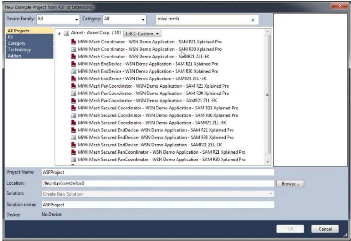
- In the New Example Project from ASF or Extensions window search for "MiWi Mesh" to list the available projects in MiWi Mesh as shown in the following screenshot.
Figure 3-1. New Example Project from ASF or Extensions Window ^(1)
text_image
New Example Project from ASF or Extensions Device Family: All Category: All miwi mesh All Projects Kit Category Technology Addon Atmel - Atmel Corp. (18) 3.38.1-Custom MiWi Mesh Coordinator - WSN Demo Application - SAM R21 Xplained Pro MiWi Mesh Coordinator - WSN Demo Application - SAM R30 Xplained Pro MiWi Mesh Coordinator - WSN Demo Application - SAMR21 ZLL-EK MiWi Mesh EndDevice - WSN Demo Application - SAM R21 Xplained Pro MiWi Mesh EndDevice - WSN Demo Application - SAM R30 Xplained Pro MiWi Mesh EndDevice - WSN Demo Application - SAMF21 ZLL-EK MiWi Mesh PanCoordinator - WSN Demo Application - SAM R21 Xplained Pro MiWi Mesh PanCoordinator - WSN Demo Application - SAM R30 Xplained Pro MiWi Mesh PanCoordinator - WSN Demo Application - SAMF21 ZLL-EK MiWi Mesh Secured Coordinator - WSN Demo Application - SAM R21 Xplained Pro MiWi Mesh Secured Coordinator - WSN Demo Application - SAM R30 Xplained Pro MiWi Mesh Secured Coordinator - WSN Demo Application - SAMR21 ZLL-EK MiWi Mesh Secured EndDevice- WSN Demo Application - SAM R21 Xplained Pro MiWi Mesh Secured EndDevice- WSN Demo Application - SAM R30 Xplained Pro MiWi Mesh Secured EndDevice- WSN Demo Application - SAMF21 ZLL-EK MiWi Mesh Secured PanCoordinator - WSN Demo Application - SAM R21 Xplained Pro MiWi Mesh Secured PanCoordinator - WSN Demo Application - SAM R30 Xplained Pro Project Name: ASFProject Location: C:\Users\Inkines\Inkines\N Browse... Solution: Create New Solution Solution name: ASFProject Device: No Device OK CancelNote:
(1) Use the latest version of ASF
- Select MiWi Mesh Coordinator - WSN Demo Application project.
- Click OK and accept the license agreement by checking the "I accept the license agreement" checkbox.
- Click Finish.
The MiWi Mesh Coordinator - WSN Demo Application project is created and loaded in Atmel Studio.
3.3.2 Switching/Changing the Configuration using ASF Wizard
If the user is using the MiWi Mesh Coordinator and needs to switch to the MiWi Mesh PANC Security, then perform the following steps.
- Choose ASF>ASF Wizard to open the ASF Wizard window.
- In the Selected Modules pane, expand MiWi-WSNDemo Application (component) and choose panc_sec from the drop-down list as shown in the following screenshot.
Figure 3-2. ASF Wizard

text_image
ASP Wizard Projects: APPS_WIN_DEMO3 Device: ATSMAR21.GSA Extensions Version Available Modules Extensions About ASPD38.1-System Show All Search for analysis AC - Analog Compactor (driver) callback ADC - Analog-to-Digital Converter (driver) callback AT301875X Temperature Sensor (component) AT40DB1 DataFlash (component) AYR262 - IEE 10.215.4 MAC v1.2.3 (component) source AYR262 - TAL (component) AYR262 - TIA (component) AYR262-MAC Serial Interface Module (service) AYR262 - RHC Control NIVCLB (service) AYR262 - RRC Control v2.0.1 (component) AYR262 - ZRC LIB For Controller (service) AYR262 - ZRC LIB For Target (service) AYR262 - Serial Interface support for RFACE (service) Selected Modules Generic Board support (driver) PORT - GPIO Pin Control (driver) SERCOM QC - Master Mode QC (driver) called Multi-WISND Demo Application (component) Serial S/O - Host Component/ switch Multi Stack (component) Stack Configuration (component) init_i_mash Mark support enable (component) MViWi MESH (component) Stack Configuration (component) PHYRadio Physical Layer (component) EVXSystem Stack Services (component) pass panc cond ed end end end end Info Actions Details MWI-WISNDemo Application The MWi based WISNDemo application implements a typical wireless sensor network scenario, in which one central mode collects the data from a network of sensors and passes this data over a serial connection for further processing. In the case of the WISNDemo this processing is performed by the WISNMonitor PC application. Add >> Apply Reset Add Remove Summary- Click Summary to understand the component changes.
- Click Apply to apply the changes to the project.
Figure 3-3. ASF Wizard-Summary of Operations for Selected Option
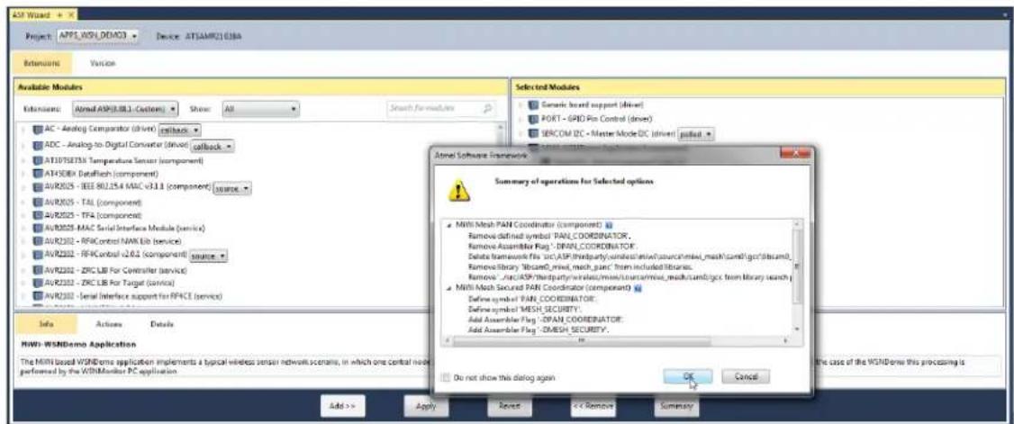
text_image
A3D Wizard Project: APPS, WSH, DDMCO Device: AT5AMR2108BA Extensions Version Available Modules Extensions: Airmi ASPB.08.1 - Custom Show: All Search for modules Selected Modules Generic Board support (driver) PORT - GPIO Pin Control (driver) SERCOM DC - Master Mode DC (driver) pulled AC - Analog Comparator (driver) callback ADC - Analog-to-Digital Converter (driver) callback AT10TERTM Temperature Sensor (component) ATHSDEX DataPatch (component) AVR202 - IEEE 80.1.5.4 MAC v3.1.1 (component) SOURCE AVR202 - TAL (component) AVR202 - TFA (component) AVR202 - MAC Serial Interface Module (service) AVR202 - RFIC control NAW Lib (service) AVR202 - RFIC control v2.6.1 (component) SOURCE AVR202 - ZFC LIB For Controller (service) AVR202 - ZFC LIB For Target (service) AVR202 - Serial Interface support for RSPACE (service) Info Actions Details MWH-WSNDemo Application The MWI based WSHDeme application implements a typical wireless sensor network scenario, in which one central node performed by the WSHMonitor PC application. Add >> Apply Reset << Remove Summary Do not show this dialog again OK Cancel Analog Software Framework Summary of operations for Selected options MWh Mesh PAN Coordinator (component) Remove defined symbol PAN COORDINATOR. Remove Assembler Flag : DMAP_COORDINATOR. Delete framework file src.ASP third-party/undest/mix/source/mix/mask/camb/gc filesand. Remove library "WasmC_rmsd_mesh_panc" from included libraries. Remove _#ac.ASP third-party/wales/mix/source/mix/mask/camb/gc from library search MWh Mesh Security PAN Coordinator (component) Define symbol PAN COORDINATOR. Define symbol MESH SECURITY: Add Assembler Flag : DPAN_COORDINATOR. Add Assembler Flag : DMESH SECURITY. HiWi-WSNDemo Application The MWI based WSHDeme application implements a typical wireless sensor network scenario, in which one central node performed by the WSHMonitor PC application3.3.3 Building the Application using IDE
Perform the following steps to build the application using IDE.
- Open an appropriate .atsIn project file from the
. \as5_arm directory with Atmel Studio. The Solution Explorer tab provides access to the application source files and stack components that compile together with the application.
Figure 3-4. Example Structure of Atmel Studio Application Project

text_image
Solution Explorer Search Solution Explorer (Ctrl+;) Solution 'APPS_WSN_DEMO3' (1 project) APPS WSN DEMO3 Build Rebuild Clean Copy Full Path Collapse Scope to This New Solution Explorer View Add Add Library Set as StartUp Project Debug ASF Wizard Board Wizard Reload Asf Project View Example Project Help Add Arduino Library Export Project as Extension Cut Ctrl+X Remove Del Rename F2 Unload Project Properties- From the main menu, choose Build>Rebuild All.
When the build process is complete, some of the .hex, .srec, .bin, and .elf image files are generated based on the selected platform configuration. Use the .hex file for programming the devices via EDBG. The .elf file is used for debugging.
3.3.4 Building the Application using Command Line Interface
Compile the application by running the make utility command to build the application.
make clean all
It is possible to run the make utility command from Atmel Studio by selecting Tools>Command Prompt. This ensures that the make utility provided with Atmel Studio is used. Otherwise, the path to the folder
containing the make utility can be added to the path environment variable. In this case, run the make utility in the command line from the application's root directory.
3.4 Building Applications in IAR Embedded Workbench
IAR Embedded Workbench can be used to develop and build MiWi applications. All reference applications include IAR project files located in the \iar sub-directory of the application root directory.
A part of stack components and drivers are compiled with the application. The source files for these components are included in the IAR projects, therefore they are an effective part of the application.
For compilation from the command line with the IAR compiler, make files are used.
3.4.1 Building the Application using IDE in IAR Embedded Workbench
Perform the following steps to build the application using IDE.
- Open the .eww file in the iar_projects sub-directory of the appropriate application directory with IAR Embedded Workbench. For example, for WSNDemo, use the APP_WSN_Demo.eww file from the apps\WSN_Demo. \iar sub directory.
- From the main menu, choose Build>Rebuild All. By default, the .a90 file (for WSNDemo, APP_WSN_Demo.a90) is generated in the \iar\Debug\exe sub directory (for WSNDemo, in the apps\WSN_Demo\iar\Debug\exe directory) with format as specified in Linker Output Options of the IAR project.
3.4.2 Building the Application using CLI in IAR Embedded Workbench
Compile the application by running the make utility command to build the application.
make clean all
Some of the .hex, .srec, .bin, and .elf image files are generated depending on the selected platform configuration.
3.5 Installing the Bootloader PC Tool
Run the bootloader PC tool installer with the following instructions.
- Navigate to the Bootloader PC Tool, available in the
\thirdparty\wireless\miwi\services\otau\tools directory. - Double click the Bootloader_PC_Tool_Setup.exe file.
- Click Next in all the pop-up windows.
- Change the installation path if required, and click Next.
- Click Done to finish the installation. For a Windows 10 PC, add the following in System Environment Variables.
Figure 3-5. Adding System Environment Variable
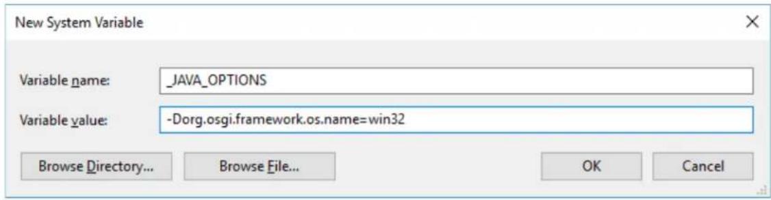
text_image
New System Variable Variable name: _JAVA_OPTIONS Variable value: -Dorg.osgi.framework.os.name=win32 Browse Directory... Browse File... OK Cancel3.6 Installing the WiDBG Tool
Run the WiDBGSetup with the following instructions.
- Navigate to the WiDBGSetup, available in the
\thirdparty\wireless\miwi\services\otau\tools directory. - Double click the WiDBGSetup.msi file.
- Accept the terms in the License Agreement and click Install.
- Click Finish to complete the installation.
4. Hardware Environment Setup
4.1 Supported Platforms and Boards
The following boards are used/supported in the 6.1 release.
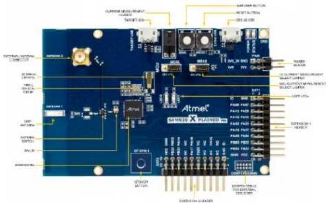
- SAM R21 Xplained Pro
Figure 4-1. SAM R21 Xplained Pro

text_image
CURRENT MEASUREMENT HEADER TARGET USB SW0 USER BUTTON RESET BUTTON DEBUG USB USER LED0 CHIP ANTENNA 16MHz CRYSTAL FOR RF ANTENNA SWITCH & BALUN EXTERNAL ANTENNA CONNECTOR ATmel SAMR21 X PLAINED 108Hz Crystal 32.768 kHz Crystal PWR SV0_IN GND SV0 SV3 PWR PWR PWR PWR PWR PWR PWR PWR PWR PWR PWR PWR PWR PWR PWR PWR PWR PWR PWR PWR PWR PWR PWR PWR PWR PWR PWR PWR PWR PWR PWR PWR PWR PWRFor more details, see SAMR21 Xplained Pro User Guide. 2. SAM R21 ZLLEK
Figure 4-2. SAM R21 ZLL-EK

text_image
MS147 connector Antenna -ANT1 USB MCU RGB LED EXTERNAL VCC (regulated) RED LED YELLOW LED USB EDBG BATTERY IN (+1.8V to +4.5V) SW FUNC RESET QMatrix BUTTON JOYSTICK NTC SENSOR Antenna -ANT2 Cortex DEBUG SAMR21G18A (stable) EDBG Serial Header XPRO POWER HEADER XPRO EXTENSION HEADER QMatrix SLIDER OLED DISPLAYFor more details, see SAM R21 ZLL-EK User Guide.
3. SAM R30 Xplained Pro
Figure 4-3. SAM R30 Xplained Pro
text_image
CURRENT INPUT, HOURS OUTPUT START BUTTON RESET BUTTON RESET BUTTON Current INPUT, HOURS OUTPUT START BUTTON RESET BUTTON RESET BUTTON Atmet® SARRED X PLATRED PRO INTEN 1 INTEN 2 INTEN 3 INTEN 4 INTEN 5 INTEN 6 INTEN 7 INTEN 8 INTEN 9 INTEN 10 INTEN 11 INTEN 12 INTEN 13 INTEN 14 INTEN 15 INTEN 16 INTEN 17 INTEN 18 INTEN 19 INTEN 20 INTEN 21 INTEN 22 INTEN 23 INTEN 24 INTEN 25 INTEN 26 INTEN 27 INTEN 28 INTEN 29 INTEN 30 INTEN 31 INTEN 32 INTEN 33 INTEN 34 INTEN 35 INTEN 36 INTEN 37 INTEN 38 INTEN 39 INTEN 40 INTEN 41 INTEN 42 INTEN 43 INTEN 44 INTEN 45 INTEN 46 INTEN 47 INTEN 48 INTEN 49 INTEN 50 INTEN 51 INTEN 52 INTEN 53 INTEN 54 INTEN 55 INTEN 56 INTEN 57 INTEN 58 INTEN 59 INTEN 60 INTEN 61 INTEN 62 INTEN 63 INTEN 64 INTEN 65 INTEN 66 INTEN 67 INTEN 68 INTEN 69 INTEN 70 INTEN 71 INTEN 72 INTEN 73 INTEN 74 INTEN 75 INTEN 76 INTEN 77 INTEN 78 INTEN 79 INTEN 80 INTEN 81 INTEN 82 INTEN 83 INTEN 84 INTEN 85 INTEN 86 INTEN 87 INTEN 88 INTEN 89 INTEN 90 INTEN 91 INTEN 92 INTEN 93 INTEN 94 INTEN 95 INTEN 96 INTEN 97 INTEN 98 INTEN 99 INTEN 100For more details, see SAM R30 Xplained Pro User Guide.
4. SAMR30M Xplained Pro
Figure 4-4. SAMR30M Xplained Pro
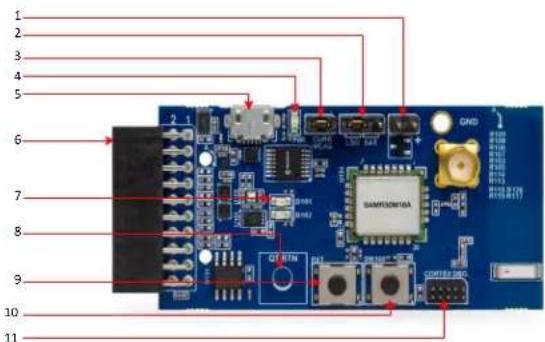
text_image
Labeled diagram of a blue electronic circuit board with numbered components and connectors-
Battery header (J102)
-
Battery/LDO Selection header (J103)
- Current measurement header (J104)
- Power LED
- USB header
- XPRO Extension header
- User LEDs
- QTouch ^® button
- Reset button
- User button
- Cortex DBG (Debug) header
4.2 Additional Boards
For Simple_Example_P2P and Simple_Example_Star applications, OLED1 Xplained PRO can be used as an additional board to show the full-featured demo on SAM R21 XPRO and SAM R30 XPRO. This board must be connected as Extension board 1.
Figure 4-5. OLED1 Xplained Pro
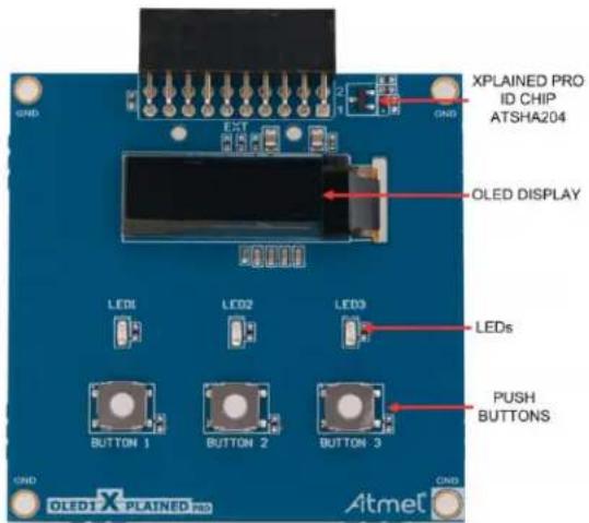
text_image
XPLAINED PRO ID CHIP ATSHA204 OLED DISPLAY LEDs LEDs BUTTON 1 BUTTON 2 BUTTON 3 PUSH BUTTONS OLED1 X PLAINED PRO AtmetFor more details, see OLED1 Xplained Pro User Guide.
4.3 Connections
Connect the Micro USB cable to the 'Debug USB/EDBG USB' port of the board and connect the other end to the PC.
Figure 4-6. Connection of SAM R21 XPRO and OLED1 XPRO
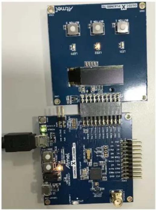
natural_image
Close-up of an Atmel X PLANSO board with various electronic components and connectors (no readable text or symbols)Figure 4-7. Connection of SAM R30 XPRO and OLED1 XPRO
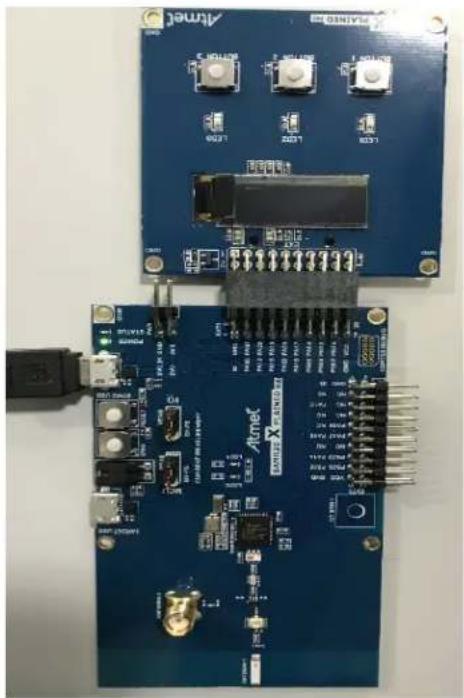
natural_image
Two electronic circuit boards with labeled components and connectors, no readable text or symbols present.5. Simple\_Example\_P2P Reference Application
The simple example application code focuses on the simplicity of the MiWi DE protocol stack application programming interfaces. It provides wireless communication between two devices with less than 30 lines of C code to run the stack in the application layer for both devices. In this application, the following features of MiWi DE protocol stack are demonstrated:
- Establish a connection automatically between two devices
- Broadcast a packet
- Unicast a packet
- Apply security to the transmitted packet
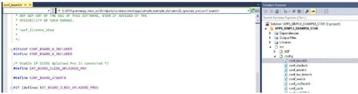
To run full-featured Simple_Example_P2P application on SAMR21 XPRO or SAMR30 XPRO, the user needs to connect OLED1 Xplained PRO. When using OLED1 Xplained PRO along with SAMR21 XPRO or SAMR30 XPRO, the user needs to enable the macro #define EXT_BOARD_OLED1_XPLAINED_PRO in conf_board.h file.
Figure 5-1. conf_board.h File

text_image
ANY WAY OUT OF THE USE OF THIS SOFTWARE, EVEN IF ADVISED OF THE POSSIBILITY OF SUCH DAMAGE. \asf_license_stop */ #ifndef CONF_BOARD_H INCLUDED #define CONF_BOARD_H INCLUDED /* Enable if OLED1 Xplained Pro is connected */ #define EXT_BOARD_OLED1_XPLAINED_PRO #define CONF_BOARD_AT8GRFX #if (defined EXT_BOARD_OLED1_XPLAINED_PRO) #define ENABLE_LCD Solution Explorer Search Solution Explorer (Ctrl+); Solution 'APPS_SIMPLE_EXAMPLE_P2P' (1 project) APPS_SIMPLE_EXAMPLE_P2P Dependencies Output Files Libraries src ASF config conf_board.h conf_clocks.h conf_extint.h conf_hw_timer.h conf_nvm.h conf_sio2host.h conf_spih conf_ssdL306.h conf_sysfont.h conf_trx_access.h mwi_config.h mwi_config_p2p.hTo run the simple example application, perform the following instructions.
- Program node 1 and node 2 with Simple_Example_P2P application firmware.
- Power on node 1 and node 2, respectively.
- Wait for few seconds, until the first LED on both nodes are powered-up. This indicates that a connection is established automatically.
- For the details of connection establishment, refer to section "Variations for Application Note AN1204 Microchin MiWi™ P2P Wireless Protocol if Mi
used. If MiWi protocol is used, refer to section "MAC Function Description" in IEEE® 802.15.4 specification.
- If the demo is running on the SAMR21 ZLLEK (or) SAMR21 XPRO with the ATOLED1-XPRO
(or) SAMR30 XPRO with the ATOLED1-XPRO, critical information is shown on the LCD of the
demo board. It first shows the demo name, RF transceiver and node number, then connecting information and channel information is displayed before the demo instruction.
Table 5-1. LCD Display
| Text on LCD Display Description | |
| Simple P2P Demo on SAMR21 Node After powering | ON the boards, this splash screen message is displayed on the LCD screen. |
| Started Wireless Communication on Channel 26 The device did not find any network to join, started new network on channel 26. | |
| Connecting Peer on Channel 26 Connecting to a network if found. | |
| Connected Peer on Channel 26 Connected to a network. This log does not show for the first device since it starts the network when it is unable to find network to join. | |
| SAM R21 ZLL EK• SW FUNC : Broadcast• BUTTOB1 : Unicast | Demo instruction is displayed. |
| SAM R21 XPRO and OLED1XPRO (or) SAM R30 XPRO and OLED1 XPRO• SW : Broadcast• BUTTOB1 : Unicast | |
- If a hyper terminal is opened to monitor firmware output, the user can see the peer device information printed out from both the nodes.
Figure 5-2. Monitor Firmware Output 1

text_image
Starting Mode 1 of Simple Demo for MiUi(IM) P2F Stack ... RF Transceiver: AT86RF233 Demo Instruction: Power on the board until LED 1 lights up to indicate connecting with peer. Push SW Button to broadcast message. LED 1 will be toggled upon receiving messages. Connecting Peer on Channel 26 Started Wireless Communication on Channel 26 My Address: 0x000425191801a532 PANID: 0x1234 Channel: 26 Connection PeerLongAddress PeerInfoFigure 5-3. Monitor Firmware Output 2

text_image
Starting Node 1 of Simple Demo for MiWi(TM) P2P Stack ... RF Transceiver: AT86RP233 Demo Instruction: Power on the board until LED 1 lights up to indicate connecting with peer. Push $W Button to broadcast message. Press Joystick CENTER Button to unicast encrypted message. LED 1 will be toggled upon receiving messages. Connecting Peer on Channel 26 Connected Peer on Channel 26 My Address: 0x000425191801b742 PANID: 0x1234 Channel: 26 Connection PeerLongAddress PeerInfo 00 00042519180186bc 09-
Press SW/SW FUNC on one node to toggle the second LED on the other node.
-
This shows how a broadcast packet is transmitted.
- If the demo is running on SAM R21 ZLLEK (or) SAM R21 XPRO with ATOLED1-XPRO (or) SAMR30 XPRO with ATOLED1-XPRO, the total number of transmitted and received messages will be shown on the LCD.
| Text on LCD Display Description | |
| TX Messages:0RX Messages: 2 | Total number of transmitted and received messages |
- If a hyper terminal is used, on the receiving end (the device that has LED2 toggled) the user can see the printout of the broadcast packet source address, signal strength, and the packet payload. The packet payload is the one line of bitmap of MiWi. Pressing the SW button at an interval of two seconds between each press on one end displays the complete bitmap of MiWi.
Figure 5-4. Bit Map of MiWi™
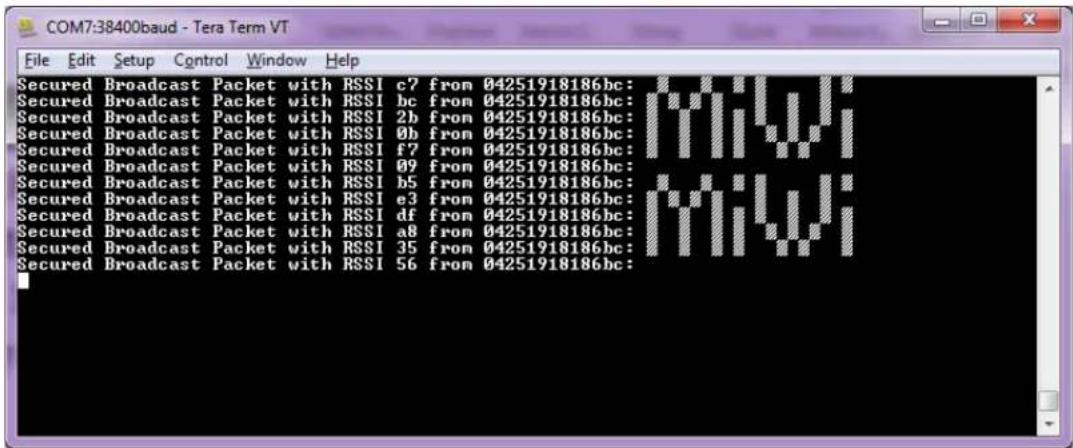
text_image
COM7:38400baud - Tera Term VT File Edit Setup Control Window Help Secured Broadcast Packet with RSSI c7 from 04251918186bc: Secured Broadcast Packet with RSSI bc from 04251918186bc: Secured Broadcast Packet with RSSI 2b from 04251918186bc: Secured Broadcast Packet with RSSI 0b from 04251918186bc: Secured Broadcast Packet with RSSI f7 from 04251918186bc: Secured Broadcast Packet with RSSI 09 from 04251918186bc: Secured Broadcast Packet with RSSI b5 from 04251918186bc: Secured Broadcast Packet with RSSI e3 from 04251918186bc: Secured Broadcast Packet with RSSI df from 04251918186bc: Secured Broadcast Packet with RSSI a8 from 04251918186bc: Secured Broadcast Packet with RSSI 35 from 04251918186bc: Secured Broadcast Packet with RSSI 56 from 04251918186bc:5. For unicast setup:
- For SAMR21ZLLEK,
- Pressing JOYSTICK center button on one node:
| Text on LCD Display Description | |
| UP : 00-42b701DOWN: Change node | Pressing JOYSTICK center button on one node |
- Pressing Joystick DOWN button selects the next device for unicast if available.
- Pressing Joystick UP button sends unicast to the selected device and toggles the second LED on the other node.
- For SAMR21XPRO and OLED1XPRO (or) SAMR30XPRO and OLED1XPRO,
- Pressing BUTTON1 center on one node:
| Text on LCD Display Description | |
| SW0 : UnicastBUTTON: Next Node | Pressing BUTTON1 center button on one node |
- Pressing BUTTON1 selects the next device for unicast if available.
-
Pressing SW0 button sends unicast to the selected device.
-
This shows how an encrypted unicast packet is transmitted and decrypted by the radio after it is received. For more details of how MiWi P2P handles encryption, refer to section "Security Features" in the AN1204 Microchip MiWi P2P Wireless Protocol Application Note.
- If the demo runs on SAM R21 ZLLEK (or) SAM R21 XPRO with ATOLED1-XPRO (or) SAMR30 XPRO with ATOLED1-XPRO, the total number of transmitted and received messages are shown on the LCD.
- If hyper terminal is used, on the receiving end (the device that has LED2 toggled), the user can see the printout of the secured unicast packet source address, signal strength, and the packet payload. The packet payload must be decrypted by the receiving device. The packet payload is the one line of bit map of "DE". Sending unicasts continuously at an interval of two seconds between each unicast/button press on one end displays the complete bit map of "DE".
Figure 5-5. Bit Map of DE

text_image
COM9:38400baud - Tera Term VT File Edit Setup Control Window Help Secured Unicast Packet with RSSI 85 from 042519181b742: Secured Unicast Packet with RSSI 85 from 042519181b742: Secured Unicast Packet with RSSI 85 from 042519181b742: Secured Unicast Packet with RSSI 85 from 042519181b742: Secured Unicast Packet with RSSI 85 from 0425181b742: Secured Unicast Packet with RSSI 85 from 042519181b742:- By default, Network Freezer is enabled in the application. The Network Freezer feature is used to store critical network information into the non-volatile memory. When the device reboots or power is rebooted, it restores the persistent data from the non-volatile memory and continues to operate in the same network with the existing network information.
If the power is rebooted on a node, the following description may be used to restore the persistent data if available in the node using the Network Freezer.
- After Step 1, the following message is shown on the LCD. The user must press the SW button within 5 seconds to boot the application from stored network parameters, or the user can press and hold the SW button immediately after power reboot till the LCD shows the following message.
Text on LCD Display
SW: Use Nwk Freezer Press in 5 sec
- If the SW button is pressed within the timeout, the application restores the data from Network Freezer and the following message is shown on LCD.
Text on LCD Display
Restoring Network !!
6. Chat\_Demo P2P Reference Application
The chat demoP2P application code focuses on the simplicity of the MiWi DE protocol stack application programming interfaces. It provides wireless communication between two devices with less than 30 lines of C code to run the stack in the application layer for both devices. In this application, the following features of MiWi DE protocol stack are demonstrated:
- Establish a connection automatically between two devices.
- Unicast a packet.
- Apply security to the transmitted packet.
To run the chat demo application, do the following.
- Program node 1 and node 2 with proper firmware.
- Power on node 1 and node 2 respectively. A hyper terminal must be opened to monitor firmware output.
- Wait for few seconds, until the first LED on both nodes are powered-up.
- The user can see the peer device information printed from both the nodes.
Figure 6-1. Node 1

text_image
COM938400baud - Tera Term VT File Edit Setup Control Window Help Chat Demo Demo Instruction: Use Console to Chat with the Peer Device Connecting to Peer... My Address: 0x00042519180186bc PANID: 0x1234 Channel: 22 Connection PeerLongAddress PeerInfo 00 00042519180184f7 00 ------------ Chat Window: ------------------ $$Figure 6-2. Node 2
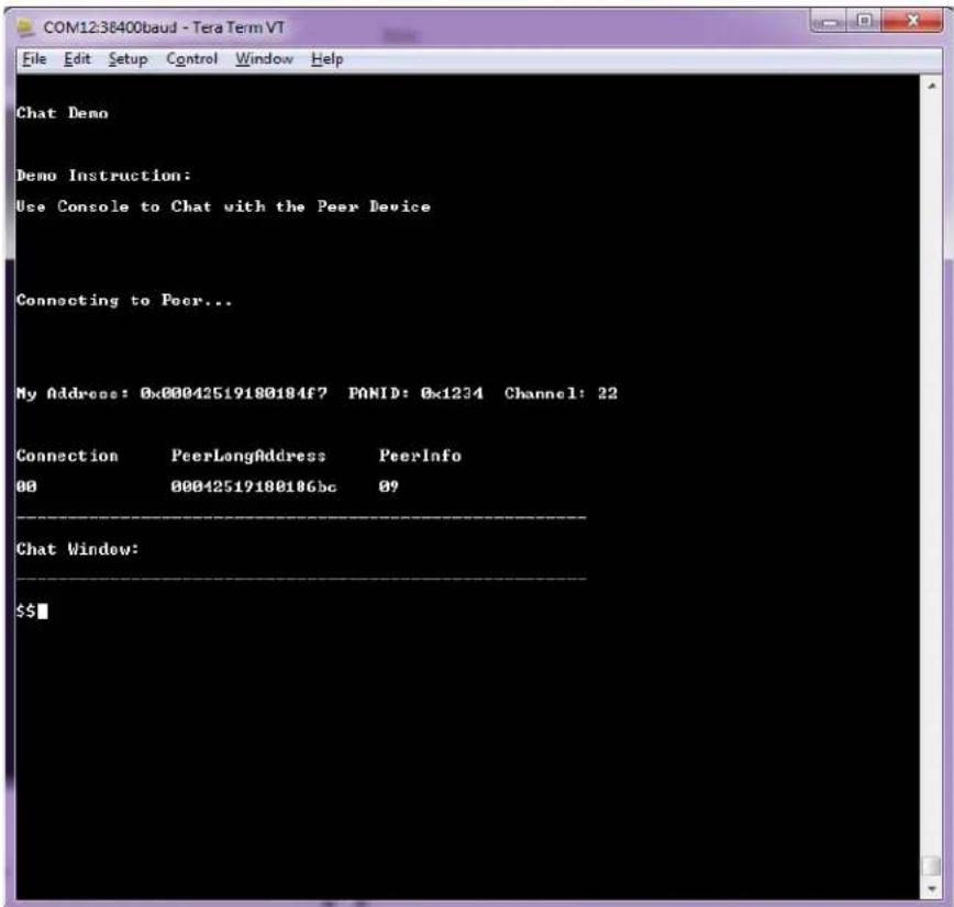
text_image
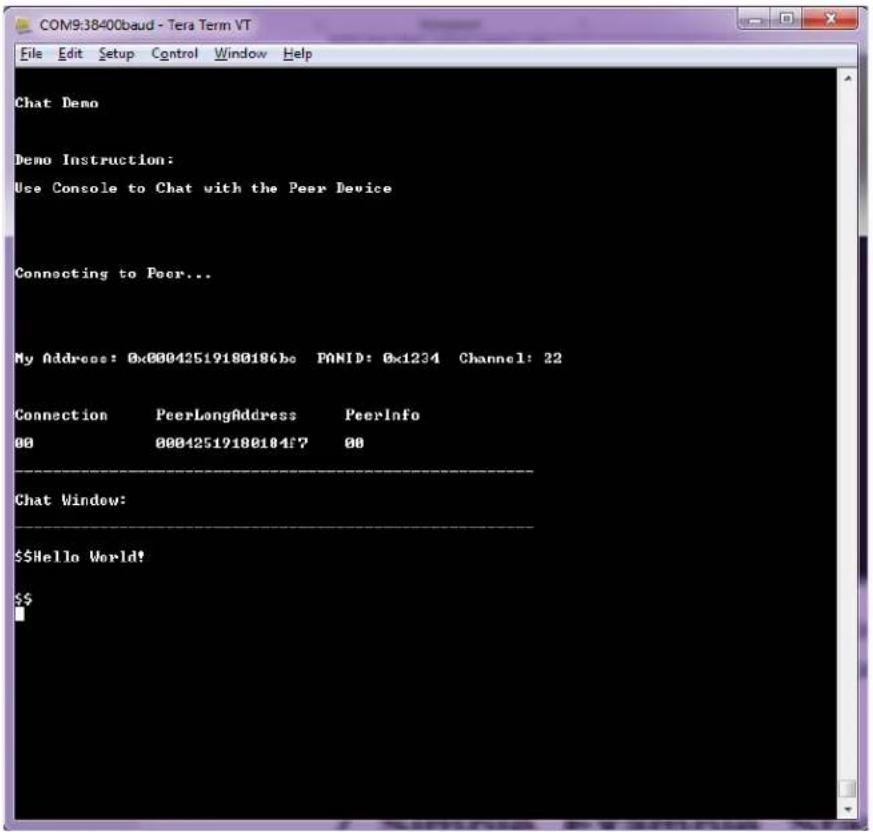
COM12:38400baud - Tera Term VT File Edit Setup Control Window Help Chat Demo Demo Instruction: Use Console to Chat with the Peer Device Connecting to Peer... My Address: 0x00042519188184f7 PANID: 0x1234 Channel: 22 Connection PeerLongAddress PeerInfo 00 00042519188186bc 09 Chat Window: $$- When the devices are connected, start typing and press Enter. For example, type 'Hello World!' on node 1 and press Enter. The user can see the entered text on node 2 as follows.
Figure 6-3. Node 1
text_image
COM9:38400baud - Tera Term VT File Edit Setup Control Window Help Chat Demo Demo Instruction: Use Console to Chat with the Peer Device Connecting to Peer... My Address: 0x00042519180186be PANID: 0x1234 Channel: 22 Connection PeerLongAddress PeerInfo 00 00042519180184f7 00 Chat Window: $$Hello World! $$Figure 6-4. Node 2

text_image
COM12:38400baud - Tera Term VT File Edit Setup Control Window Help Chat Demo Demo Instruction: Use Console to Chat with the Peer Device Connecting to Peer... My Address: 0x00042519180184f7 PANID: 0x1234 Channel: 22 Connection PeerLongAddress PeerInfo 00 00042519180186bc 09 Chat Window: $$ —— Fran [04251918186bc] : Hello World! $$■7. Simple\_Example\_Star Reference Application
The simple example application code focuses on the simplicity of the MiWi DE protocol stack application programming interfaces. It provides wireless communication between two devices with less than 30 lines of C code to run the stack in the application layer for both devices. In this application, the following features of MiWi DE protocol stack are demonstrated:
- Establish a connection automatically between PAN coordinator and end device.
- Broadcast a packet.
- Unicast a packet from one end device to another end device through PAN coordinator.
- Apply security to the transmitted packet.
By default, the Network Freezer is enabled in the application. The Network Freezer feature is used to store critical network information into the nonvolatile memory. Star network is supported on three different Hardware Development Boards and works as described in the following configurations.
Figure 7-1. Star Network Configuration
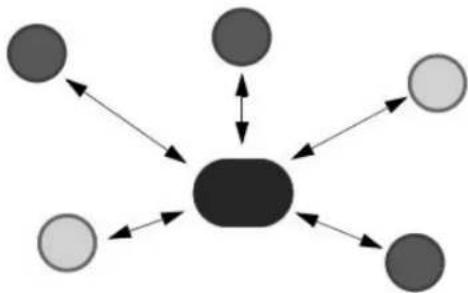
flowchart
graph TD
    A["●"] --> B["●"]
    C["●"] <--> B
    D["○"] --> B
    E["●"] --> F["●"]
    G["○"] --> F
    H["●"] --> F
    I["○"] --> F
To run full-featured Simple_Example_Star application on the SAMR21 XPRO or SAMR30 XPRO, the user needs to connect the OLED1 Xplained PRO. When the OLED1 Xplained PRO is used along with the SAMR21 XPRO or SAMR30 XPRO, then the user needs to enable the macro #define
EXT BOARD OLED1 XPLAINED PRO in conf board.h file.
Figure 7-2. conf_board.h File
text_image
conf_board.h E:\SYN\premerge Player ur\thirdparty\wireless\rmw\apps\simple_example_starsmm21_splained_pro\conf_board.h ANY MAY OUT OF THE USE OF THIS SOFTWARE, EVEN IF ADVISED OF THE POSSIBILITY OF SUCH DAMAGE. \asf_license_stop */ #1\ndef CONF_BOARD_H INCLUDED #define CONF_BOARD_H INCLUDED /* Enable If OLED1 Xplained Pro is connected */ #define EXT_BOARD_OLED1_XPLAINED_PRO #define CONF_BOARD_ATB6NFX #if (defined EXT_BOARD_OLED1_XPLAINED_PRO) Solution Explorer Search Solution Explorer (Ctrl+) Solution 'APPS_SIMPLE_EXAMPLE_STAR (I project) APPS_SIMPLE_EXAMPLE_STAR Dependencies Output Files Libraries src ASF config conf_board.h conf_clocks.h conf_extint.h conf_hx_timer.h conf_rwm.h conf_pio2host.h conf_spih- Perform the following.
Table 7-1. LCD Display
| Text on LCD Display Description | |
| Simple STAR on SAMR21 Node After powering ON | the boards, this splash screenmessage is displayed on the LCD screen. |
| ......continued | |
| Text on LCD Display Description | |
| Started Wireless Communication on Channel 25 The device did not find any network to join, started new network on channel 25. | |
| Connecting Peer on Channel 25 The LCD screen displays the operating channel. | |
| Connected Peer on Channel 26 Connected to a network. This log does not show for first device since it starts network when it is unable to find network to join. | |
| SAM R21 ZLL EK• PC : SW FUNC to BroadcastSAM R21 XPRO and OLED1XPRO (or) SAM R30 XPRO and OLED1 XPRO• PC : SW to Broadcast | If no network is found, the node creates its own network and acts as a MiWi^TM PAN coordinator. |
| Connected Peer on Channel 25 If any other MiWi | ^TM PANCO node is found in the vicinity, then it gets connected to the PAN coordinator as End Node. |
Hyper terminal shows the following on successful connection.
Figure 7-3. Node Starting the Network (PANC)
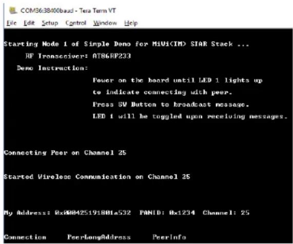
text_image
COM36:38400baud - Tera Term VT File Edit Setup Control Window Help Starting Node 1 of Simple Demo for MiUi(IM) SIAR Stack ... RF Interceiver: AT86RP233 Demo Instruction: Power on the board until LED 1 lights up to indicate connecting with peer. Press 5V Button to broadcast message. LED 1 will be toggled upon receiving messages. Connecting Peer on Channel 25 Started Wireless Communication on Channel 25 My Address: 0x000425191801a532 PANID: 0x1234 Channel: 25 Connection PeerLongAddress PeerInfoFigure 7-4. Node Joining the Network (PANC)

text_image
Starting Mode 1 of Simple Demo for MIVs(TM) STAR Stack ... HP Transducers: A10680233 Demo Instruction: Power on the board until IEB 2 lights up to indicate connecting with peer. Press SV Button to broadcast message. IEB 1 will be toggled upon receiving messages. Connecting Peer on Channel 25 Connected Peer on Channel 25 My Address: 0x0042519100186bc PMID: 0x1274 Channel: 25 Connection PageLengthAddress PageInfo 0004251910018742 01Note: For every 15 seconds, PAN CO broadcasts the connection table to all the end nodes and, the end nodes send the link status back to PAN CO. After the PAN coordinator has established a network, power on a second node and follow the instructions in Step 5 to join the PAN Coordinator. This process may be repeated to add any number of Nodes to the network.
- After getting connected to PAN Coordinator, the LCD displays options to unicast a message to either the PAN coordinator or to another node in the network.
2.1. For SAMR21ZLLEK:
| Text on LCD Display Description | |
| Press JoyStick Center to Unicast Pressing joystick center button on one node | |
| UP:00-42b701 meDOWN: Change node | Pressing joystick UP button sends the unicast message |
2.2. For SAMR21XPRO and OLED1XPRO (or) SAMR30XPRO and OLED1XPRO:
| Text on LCD Display Description | |
| SW0 : UnicastBUTTON: Next Node | Pressing BUTTON1 displays the next node to choose |
| SW0:02-bc8601-meBUTTON1: Change node | Pressing SW0 button sends unicast to the selected device. |
- Pressing joystick DOWN push button on the node on the SAMR21ZLLEK (or) pressing BUTTON 1 on the SAMR21XPRO+OLED1XPRO or SAMR30XPRO+OLED1XPRO, displays the address of the next node in the unicast address selection list.
The LCD screen displays the three bytes of the short address followed by "me" keyword indicating its MAC address in the list, or MAC address of the next node in the unicast address selection list. Depending on the location within the list, the LCD screen shows one of the following texts:
| Text on LCD Display Description | |
| UP:00-42b701 meDOWN: Change node | SAM R21 ZLL EK |
| SW0:02-bc8601-meBUTTON1: Change node | SAMR21XPRO and OLED1XPRO (or)SAMR30XPRO and OLED1XPRO |
- If joystick UP push button on the SAMR21ZLLEK (or)
SW0 button on the SAMR21XPRO and OLED1XPRO (or) SAMR30XPRO and OLED1XPRO is pressed at the end node, a unicast message is sent to,
- the PAN Coordinator when indicated as, "xx-xxxxxx-me" (or)
- the destination node when indicated as, "xx-xxxxx".
After a successful transmission, the TX value is incremented at the source end node. The RX value is incremented at the destination node (PAN CO) and three bytes of source MAC addresses are displayed.
| Text on LCD Display Description | |
| TX Messages: 2RX Messages: 4 | In the nodes, LCD displays the number of transmitted and received messages. |
| Data Packet from Address:f78401 After one second, | the LCD display shows this message. |
- If Joystick DOWN push button on the SAMR21ZLLEK or BUTTON 1 on the SAMR21XPRO and OLED1XPRO (or) SAMR30XPRO and OLED1XPRO is pressed at the end node, the LCD displays the next node available in the connection table.
UP: 01-XXXXXX
DOWN: Change Node
Note: At the end nodes, UP push button on the SAMR21ZLLEK or SW0 button on the SAMR21XPRO and OLED1XPRO (or) SAMR30XPRO and OLED1XPRO is used to unicast message to the selected node. DOWN push button on the SAMR21ZLLEK or BUTTON 1 on the SAMR21XPRO and OLED1XPRO (or) SAMR30XPRO and OLED1XPRO is used to change or select the other destination node of the unicast message.
- Press SW button at PAN CO to broadcast message to all the end nodes in the network. The LCD displays the incremented TX values.
TX: xx, RX: yy
Message Count
Note: When the destination node receives the message from source (end nodes or PAN CO), the RX value is incremented. The respective nodes display the three bytes of source MAC address from which they received the message.
- After few seconds, the display reverts to following messages on the LCD display.
| Text on LCD Display | |
| PC : SW FUNC to Broadcast At PAN CO | |
| Press Joystick Center to Unicast At source or destination end nodes | |
Hyper terminal shows the following upon many broadcasts from the PAN coordinator.
Figure 7-5. Hyper Terminal Output
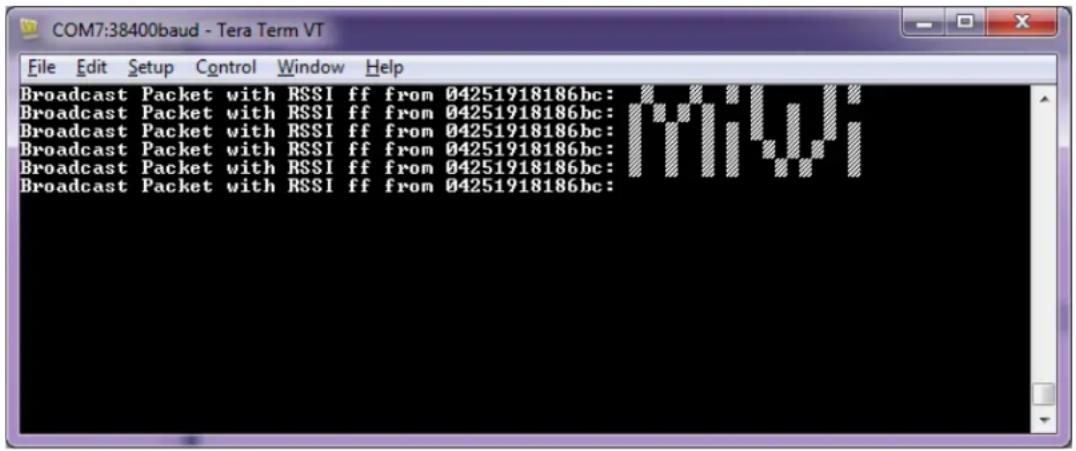
text_image
Broadcast Packet with RSSI ff from 04251918186bc: Broadcast Packet with RSSI ff from 04251918186bc: Broadcast Packet with RSSI ff from 04251918186bc: Broadcast Packet with RSSI ff from 04251918186bc: Broadcast Packet with RSSI ff from 04251918186bc:- When the device reboots or power is rebooted, it tries to restore the existing data from the nonvolatile memory and continues to operate in the same network with existing network information.
After a reboot, perform the following steps using the Network Freezer to restore the existing data in the node:
- After Step 1, the LCD displays (SW: Use Nwk Freezeer Press in 5 sec) message. Press the SW button within 5 seconds to boot the application from stored network parameters, or the user can press and hold the SW button immediately after the power reboot till the LCD displays the following message.
Text on LCD Display
SW: Use Nwk Freezer
Press in 5 sec
- If the SW button is pressed within the timeout, the application restores the data from the Network Freezer and the LCD displays the following message.
Text on LCD Display
Restoring Network !!
8. WSN Demo Mesh Reference Application
The WSNDemo application is based on the MiWi API. This application demonstrates the network and radio frequency performance of the hardware components. This application consists of the embedded firmware, which supports functions for PAN coordinator, coordinator, end device, GUI visualization application, and WSNMonitor, which runs on a PC. In the WSNDemo, the nodes communicate based on a proprietary messaging protocol.
The package includes the WSNMonitor PC application in binary format, and the WSNDemo embedded application is available in binary format and source code. The source code for the WSNDemo application can be modified and extended to develop WSN applications for a variety of application scenarios.
The end devices, coordinators, and PAN coordinator devices emulate the sensor data reading for light and temperature sensors, and forward collected data to the WSNMonitor application for visualization. The end devices follow a duty cycle to transmit data to the coordinator. Using the serial connection, the PAN coordinator transmits the received packets, along with its own sensor data (or emulated sensor data), to the WSNMonitor application. Those transmitted values are displayed on the WSNMonitor panes as temperature, light, and battery level measurements.
The WSNMonitor also visualizes network topology by drawing a tree of nodes that have joined the network. For each of the nodes, parameters like node address, node sensor information, and link quality data are displayed.
- RSSI indicates a link's current condition and is measured in dBm. The RSSI resolution is 3 dBm.
- LQI is a numeric parameter defined within the 0 to 255 range, is used to measure the link quality. Larger values mean to have a better link, while values close to zero indicate a poor connection.
The Network Freezer feature is used to save or store critical network information into the non-volatile memory. By default, Network Freezer is enabled in WSN Demo application.
When the device reboots, it restores the existing data from the non-volatile memory and continues to operate in the same network with existing network information.
By default, the sleep feature is enabled in the end device application. Both the MCU and transceiver are in sleep when the device is idle.
8.1 Launching the Demo
Perform the following steps to launch the demo application.
- Assemble the devices.
- Program the devices with firmware images. One node must be programmed as PAN coordinator, and the others as coordinators or end devices.
-
Connect the PAN coordinator node to the PC using the serial interface.
-
Run the WSNMonitor.
Use the following setting for the serial connection of the WSNMonitor:
- BAUD RATE – 38400
- PARITY – None
- DATA BITS - 8
- STOP BITS - 1
-
FLOW CONTROL – Off (On for the XPRO board)
-
Observe the coordinator node in the WSNMonitor.
-
Power on the other nodes and observe them displayed in the WSNMonitor.
- Select any coordinator node and click on the bulb icon next to it, and observe the device blink its LEDs.
The SW button on the board is used to erase all the existing items in the memory and reset the device as a factory new device.
8.2 Network Startup
The PAN coordinator organizes the wireless network automatically. Upon starting the network, every node informs the network of its role. When the PAN coordinator is powered on, it switches to an active state even though no child node is present. This behavior is normal. It indicates that the PAN coordinator is ready and the child nodes can join the network with the coordinator's PAN ID. By default, the coordinator uses PAN ID 0x1234, which is recognized by all the coordinators. The PAN ID can be modified by the user through the application's configuration file.
If the PAN coordinator is absent or has not been turned on, the coordinators and end devices remain in the Network Search mode. In this mode, the coordinators scan the channels specified in the channel mask in search of a network. By default, the channel mask in the application provided with the release contains a single channel. On rare occasions, if the frequency corresponding to the radio channel is busy, the coordinator node may stay in the network search mode. If this happens, it may become necessary to change the application's channel mask to select another channel by changing the application's configuration file and recompiling the application.
Network health can be monitored through the WSNMonitor application.
8.3 WSNMonitor
The WSNMonitor is a PC counterpart to the WSNDemo embedded application. It can be used to display MiWi mesh network topology and other information about a wireless sensor network. A typical WSNMonitor screen is shown in the following figure. It contains topology, sensor data, node data panes, and application toolbars.
The following is a sample topology of MiWi Mesh protocol.
Figure 8-1. WSNMonitor Showing Topology of MiWi™ Mesh Protocol
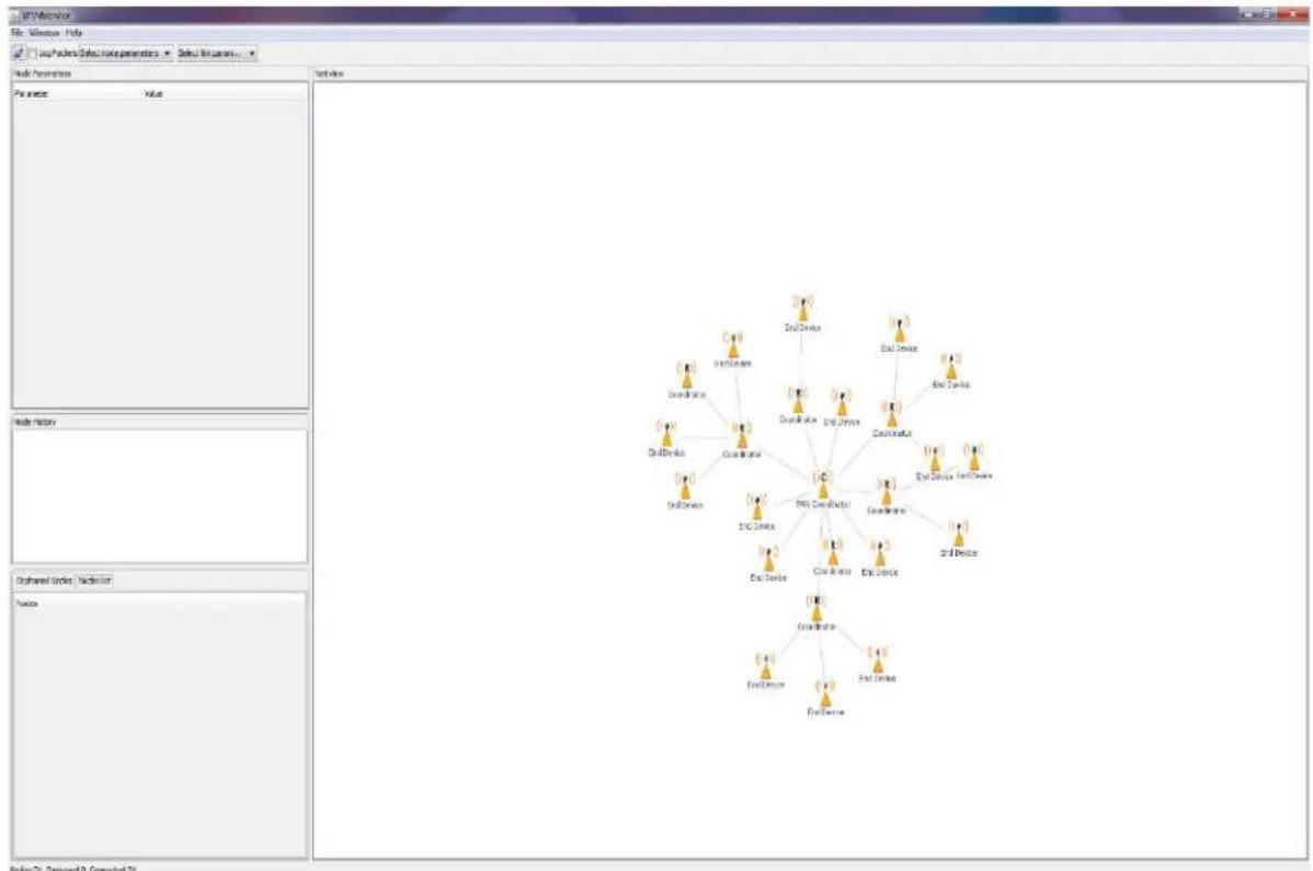
The topology pane displays the network topology in real time. This helps the user to monitor:
- the formation of the network,
- dynamic changes while nodes join,
- nodes sending data across, or,
- when nodes leave the network.
The network topology is constructed on the basis of next-hop information for each of the nodes. Each link is also tipped with RSSI and LQI values. Each of the nodes has an icon, with the node's address or name below and sensor readings to the right of the icon, if required by settings.
The sensor data pane displays data coming from onboard sensors of the selected node. It is presented in graph and table format. Other parameters for each node are available in a table format. The node data pane includes a sensor selection combo-box, which is used to switch between sensor types.
By default, in the topology pane, nodes are labeled with their short addresses. Double click to assign another title to any desired node. Press 'Cancel' to set back the node's title to the short address.
Figure 8-2. WSNMonitor Window Description

text_image
WSNMonitor File Window Help Menu bar Log Packets Select node parameters Select link param... Node Parameters Param... Mest Node FullAddr... 000000000000027 ShortAd... 0x1C02 Softwar... 0x0:10:10:100 Channel... 0x0:1000000 PenID 0x28E2 Working... 0x18 ParentA... 0x4308 LOI 252 Net view Serial port settings Show additional data on the topology pane (LQI, RSSI, or sensor data) Specific parameters for the selected node Router node Topology pane Node History Battery Temperature Light ShortAddress LQI RSSI Time Value 15:46:41.643 0x1C02 Sensor data pane Coordinator node Selected node Orphaned Nodes Nodes list FullAddress Filter: Nodes 00-00-00-00-00-00-00-06 00-00-00-00-00-00-00-07 00-00-00-00-00-00-00-29 00-00-00-00-00-00-00-05 00-00-00-00-00-00-00-19 00-00-00-00-00-00-00-12 00-00-00-00-00-00-00-10 00-00-00-00-00-00-00-04 List of connected nodes Click to make the node identify itself by flashing LED Nodes:29 Orphaned:O Connected:298.4 Identifying Nodes
When the user clicks a node in the topology pane, a button to identify the node appears under the node's icon. When the user clicks this button, WSNMonitor sends a command which is delivered to the PAN Coordinator through a serial connection and wirelessly to the target node. After receiving the command, the target node blinks with its LED for several seconds.
When the user clicks the PAN Coordinator node's identify icon, the PAN Coordinator blinks and it sends a broadcast message to identify the active nodes in the network. Therefore, all the active nodes blink after receiving the command.
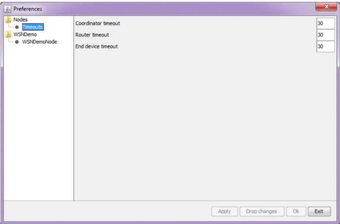
8.5 Node Timeouts
The Window/Preferences menu of the WSNMonitor contains a number of parameters that can be used to control the application. Timeouts are used to tune visualization of the PAN coordinator, the coordinator, and the end devices when the nodes disappear from the network when a connection is lost, power is down, or a reset has occurred. A node timeout corresponds to the time the WSNMonitor application waits for a packet from a particular node before assuming that the node is no longer part of the network.
Note: This value does not correspond to the frequency with which data are transmitted by each type of the device.
To get smooth topology visualization, it is recommended to set timeouts at 20 seconds for the PAN coordinator and the coordinator, and 30 seconds for an end device. Assuming a default application configuration, these timeouts cover three periods between sending a packet. Therefore, at least three packets must be lost before a node is removed from the WSNMonitor topology pane.
Figure 8-3. WSNMonitor Preferences Menu
text_image
Preferences Nodes ● Timeouts WSNDemo ● WSNDemoNode Coordinator timeout Router timeout End device timeout 30 30 30 Apply Drop changes Ok ExitIn WSNMonitor, the PAN coordinator refers to the coordinator, the coordinator refers to the router, and the end device refers to the end device.
8.6 Sensor Data Visualization
Each board sends temperature, light, or battery sensor values (or emulated values) to the PAN coordinator, which in turn sends it to the PC. The WSNMonitor displays the values from onboard sensors next to a node icon inside the topology pane. A corresponding option can be selected in the node or link parameters from the quick settings toolbar.
The user can select any node in the topology pane to monitor the node's activity and the node data in one of the following three different forms:
- Text
- Table
- Chart
The onboard sensor data is displayed next to each node in the topology pane. These values are tipped with arrows indicating whether the value increased or decreased in relation to the previous sample. A given node is selected when it is clicked and a dashed frame is visible around it.
The sensor data pane displays the same values. This helps the user to observe how the values change over a period of time. The sensor data pane includes a sensor selection combo-box. Use the button on the sensor control toolbar to display the desired types of sensor data.
9. OTAU in WSNDemo Mesh Application
9.1 Software Prerequisites
- The Bootloader PC Tool is available in the
\thirdparty\wireless\miwi\services\otau\tools directory. For more details on the installation procedure, see 3.5 Installing the Bootloader PC Tool. - WiDBGSetup.msi is available in the
\thirdparty\wireless\miwi\services\otau\tools directory. For more details on the installation procedure, see 3.6 Installing the WiDBG Tool. - Bootloader files for SAMR21 and SAMR30 are available at
\thirdparty\wireless\miwi\services\otau\tools.
9.2 OTAU Client
9.2.1 Memory Layout of Client
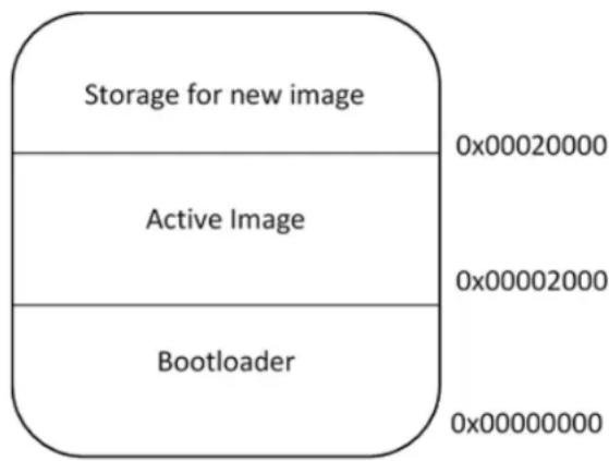
To upgrade the application from WiDBG UI, the serial bootloader in the AVR2054 is modified to support internal Flash swap functionality. The last page (of size 64 bytes) of Flash is used to store the information for the bootloader to perform a Flash swap. The following figure displays the memory layout of the client if the image is stored in the internal Flash.
Figure 9-1. Internal Flash
text_image
Storage for new image Active Image Bootloader 0x00020000 0x00002000 0x00000000The user has an option to use external Flash for storing the new image. The SAMR30 Module Xplained Pro board has AT25DFX041B external Flash. To use the external memory for storing the image, add symbol OTAU_USE_EXTERNAL_MEMORY in the project configuration as shown in the following screenshot.
Figure 9-2. Adding OTAU_USE_EXTERNAL_MEMORY Symbol

text_image
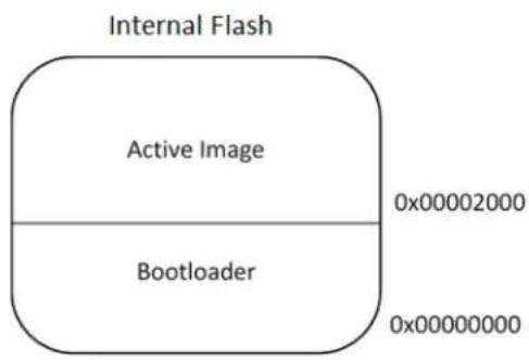
Build Build Events Toolchain Configuration Manager... Device Tool Packs Advanced ARM/GNU Common General Output Files ARM/GNU C Compiler General Preprocessor Symbols Directories Optimization Debugging Warnings Miscellaneous ARM/GNU Linker General Libraries Optimization Memory Settings Miscellaneous ARM/GNU Assembler General Debugging ARM/GNU Preprocessing Assembler General Symbols Debugging ARM/GNU Archiver ARM/GNU C Compiler ➕ Symbols Defined symbols (-D) ARM_MATH_CMOPLUS=true BOARD=SAMF30_XPLAINED_PRO ENABLE_NETWORK_FREIZER ENABLE_SLEEP_FEATURE EXTINT_CALLBACK_MODE=true I2C_MASTER_CALLBACK_MODE=false MESH_SECURITY Undefined symbols (-A) Add Defined symbols (-D) Defined symbols (-D) OTAU_USE_EXTERNAL_MEMORY OK CancelThe memory layout is shown in the following figure.
Figure 9-3. Memory Layout
text_image
Internal Flash Active Image 0x00002000 Bootloader 0x00000000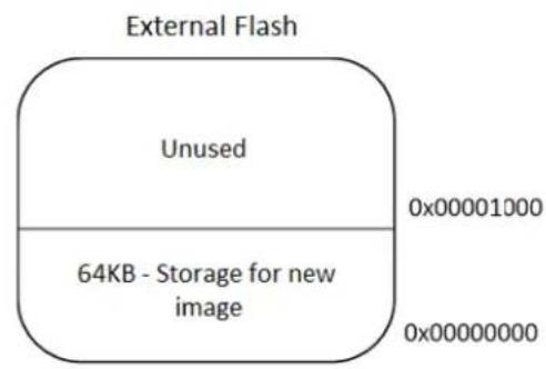
text_image
External Flash Unused 0x00001000 64KB - Storage for new image 0x000000009.2.2 Programming Client Firmware
Perform the following steps to program the client firmware.
- Select a WSN Demo application with required device type. For more details, see 3. Development Environment Setup.
- Open
\thirdparty\wireless\miwi\services\pds\src\wl\linkerscripts\samr21\gcc\samr21g18a_flash.ld. - Modify the memory region of ROM from 0x00000000 to 0x00002000 as:
/* Memory Spaces Definitions */
MEMORY
{
    rom (rx) : OROGIN = 0x00002000, LENGTH = 0x00040000
    ram (rwx) : OROGIN = 0x20000000, LENGTH = 0x00008000
}
- Rebuild the project.
- Program the client node with bootloader elf file available in
\thirdparty\wireless\miwi\services\otau\tools. - Open the Bootloader PC Tool and configure the serial settings as shown in the following figure.
Figure 9-4. Bootloader PC Tool Serial Settings
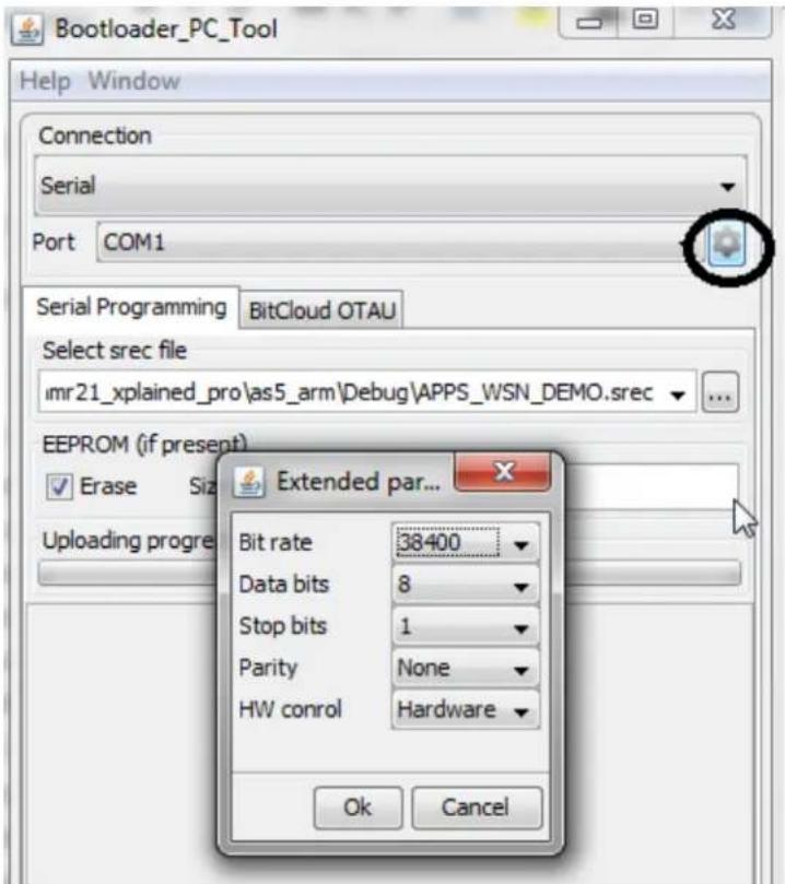
text_image
Bootloader_PC_Tool Help Window Connection Serial Port COM1 Serial Programming BitCloud OTAU Select src file imr21_xplained_pro\as5_arm\Debug\APPS_WSN_DEMO.srec EEPROM (if present) ✓ Erase Size Extended par... Uploading progress Bit rate 38400 Data bits 8 Stop bits 1 Parity None HW conrol Hardware Ok Cancel- Select the APP_WSN_DEMO.srec file from the project directory which is generated at Step 4, and click Upload button.
- To start upload, reset the client node.
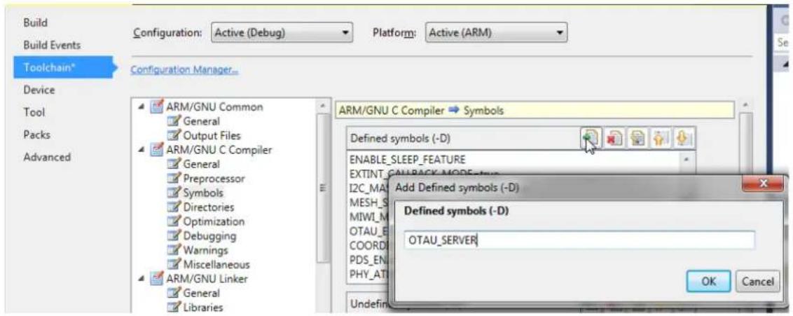
9.3 OTAU Server
Note: The PAN coordinator cannot be used as OTAU Server because the PAN coordinator uses the serial interface to communicate to the WSNMonitor. However, the PAN coordinator can be configured as OTAU Client.
- Configure the WSN Demo application as coordinator (see 3. Development Environment Setup).
- Add the OTAU_SERVER in symbol as shown in the following screenshot.
- Click OK.
Figure 9-5. Add Defined Symbols Dialog Box
text_image
Build Build Events Configuration: Active (Debug) Platform: Active (ARM) Toolchain* Configuration Manager... Device Tool Packs Advanced ARM/GNU Common General Output Files ARM/GNU C Compiler General Preprocessor Symbols Directories Optimization Debugging Warnings Miscellaneous ARM/GNU Linker General Libraries ARM/GNU C Compiler ➕ Symbols Defined symbols (-D) ENABLE_SLEEP_FEATURE EXTINT_CALLBACK_MODEFeature I2C_MA MESH_S MIWI_M OTAU_E COORDI PDS_EN PHY_AT Add Defined symbols (-D) Defined symbols (-D) OTAU_SERVER OK Cancel- Compile and program the OTAU server node. When the node joins the network with the available coordinator, the WSNMonitor is updated as shown in the following figure.
Figure 9-6. OTAU Server Node in WSNMonitor

flowchart
graph TD
    A["Client-PAN Coordinator-0x0000"] --> B["C"]
    A --> C["R"]
    C --> D["Server-Coordinator-0x0100"]
10. Atmel WiDBG for OTAU
When the installation of WiDBGSetup.msi is completed, a shortcut is created on the desktop. Double click and open the WiDBG.
Figure 10-1. Opening WiDBG Tool

text_image
Atmel WiDBG 1.0 Atmel Wireless Debugging Tool Starting up... © 2015 - All Rights Reserved. Atmel Corporation.10.1 Starting the Session
This section explains how to start the session using the WiDBG tool. Ensure that the server node is connected to the Host Machine (PC) via USB.
- Open the WiDBG application.
- Choose Settings>Connection.
- In the Settings dialog box, select the desired COM port and click OK to save the settings.
Figure 10-2. Serial Port Settings
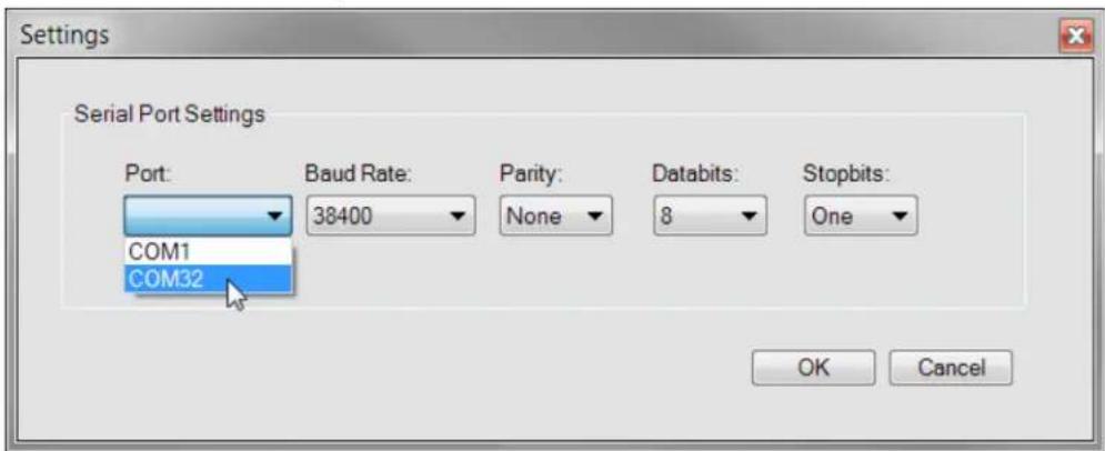
text_image
Settings Serial Port Settings Port: Baud Rate: 38400 Parity: None Databits: 8 Stopbits: COM1 COM32 OK Cancel- To connect to the OTAU server, perform the following:
4.1. Choose Session>Connect>Serial Port. When successfully connected, the connection success status message is displayed.
4.2. Select the desired channel number from the drop-down list.
- Click Start to start the debugging session.
10.1.1 Notification Settings
When the session is started, all the OTAU clients start to notify after configuring the notification interval. This section explains how to configure the notification intervals of the clients.
Depending on the number of client nodes, the user can adjust the interval; therefore, the traffic on the channel can be minimized for effective debugging during the session. By default, all clients notify the server every five seconds. This can be changed if the number of nodes is higher.
- Click the Refresh Notification icon to open the Notify Interval Settings window. The properties are set as follows:
Figure 10-3. Refresh Notification

Figure 10-4. Notify Interval Settings for the Client
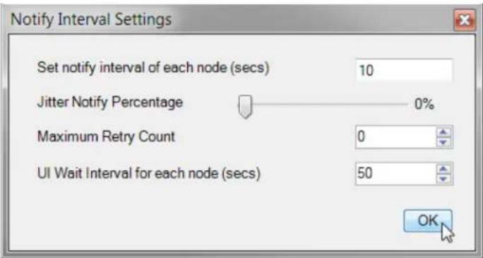
text_image
Notify Interval Settings Set notify interval of each node (secs) 10 Jitter Notify Percentage 0% Maximum Retry Count 0 UI Wait Interval for each node (secs) 50 OK- Notify Interval - Client Notify Interval Setting
This is the interval assigned to each client node of the network. When it receives the value from the tool it starts sending the notification to the user according to the specified interval.

Tip: For example: If 5 clients are connected to the server and the time is set to 10 seconds, then each client will send a notification to WiDBG on the 10th, 20th ... and so on after it receives the value from tool until we change or stop the session.
- Jitter Notify Percentage - Jitter Notify Percentage Setting
This is the percentage value assigned to each client to randomize the time to avoid the collision when the other client is notifying at the same time. By default, randomization is not applied to the clients.

Tip: Increase the percentage if the network is large and decrease the percentage if the network is small.
- Maximum Retry Count - Retry Count Setting
If the notification is not recognized by the tool due to heavy traffic, it forces the client to retry the notification for specified count value.
- UI Wait Interval - UI Wait Interval Setting
The user must set the minimum wait time for the tool to decide a node whether it is active, using UI Wait Interval settings from Preferences window.

Tip: The user must set the timing accordingly at UI Wait Interval based on Notify Interval Value.
By default, the timing is configured as:
- Notify Interval for Client = 5 seconds
- UI Wait Interval for WiDBG = 15 seconds
Therefore, the WiDBG waits for 15 seconds which is three times the client notify interval setting to decide is a node as ACTIVE.

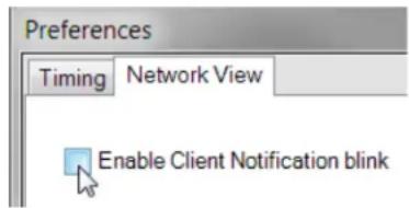
Tip: Users can see the client's notification by enabling the Enable Client Notification blink checkbox from Settings>Preferences>Network View Settings. When the Enable Client Notification blink checkbox is enabled, the node blinks as GREEN color for a moment when it is responding to the tool.
Figure 10-5. Network View
text_image
Preferences Timing Network View Enable Client Notification blink- Identify all the clients using Identify All button.
Click the Blink All icon to blink all the nodes connected to the network. This blinks by toggling its board LED.
Figure 10-6. Blink All

10.2 Main Window
The Main window summarizes nearly all the information of the connected network. When the session is started, this window provides information on the stability of the system at any time to the user. This window provides the following information:
- Table View
- Network Topology View
- Output View
Each view is designed to provide useful information about connected clients. The network view and table view are interconnected to each other. It gives clarity to the user to perform analyzing tasks on each node. Also, both the views are lively in nature and reflect the status of nodes immediately with the time stamp.
Figure 10-7. Main Window
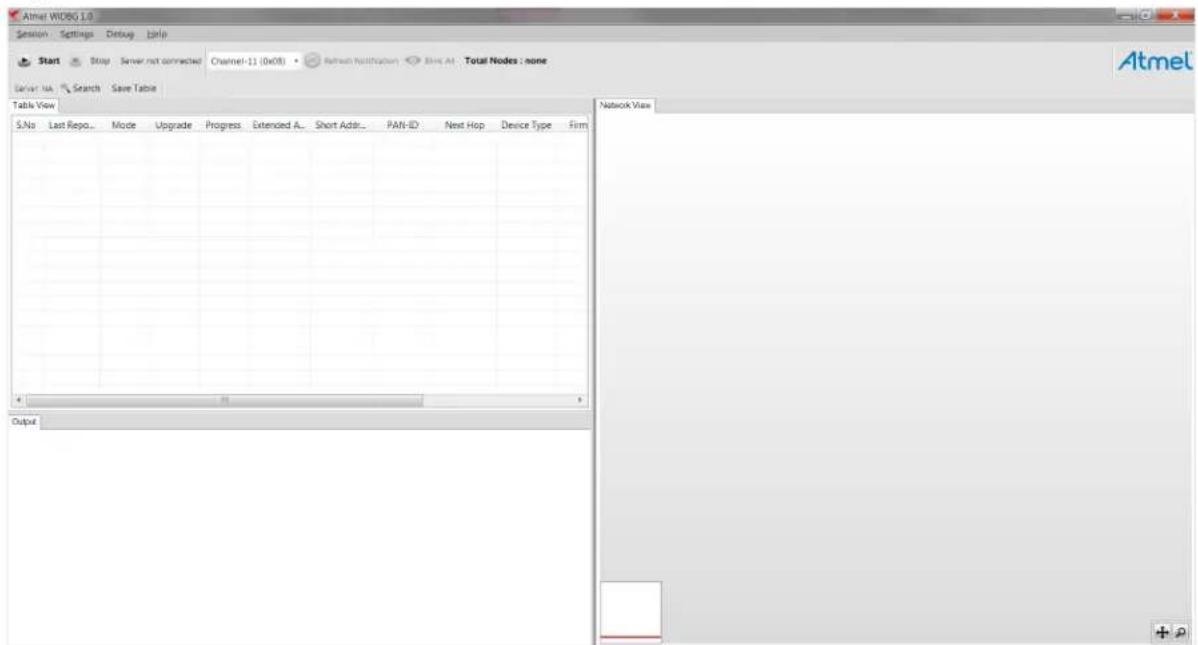
text_image
Atmel WOBG 1.0 Session Settings Debug Help Start Stop Server not connected Channel-11 (db08) Refresh Notification Blue AI Total Nodes: none Server/Bus Search Save Table Table View S.No Last Repo... Mode Upgrade Progress Extended A... Short Addr... PAN-ID Next Hop Device Type Firm Network View Output10.2.1 Table View
The Table View lists all the nodes that are connected to the network. It has useful information about the node. Each node occupies a row with several columns, as shown in the following screenshot.
Figure 10-8. Table View
| S.No | Last Repo. | Mode | Upgrade | Progress | Extended Address | Short Address | Device Type | Parent | LQI | Supported... | Firmware | Firmware v.. | Board | Board versi... |
| 1 | 17:08:53 | APP | Upgrade | 0x1122334455667788 | 0x1 | LWMesh | 1.2.1 | SAMR21XPro | 1.0.0 | |||||
| 2 | 17:11:40 | APP | Upgrade | 0x4250000005002 | 0x5002 | Router | 0x1 | 228 | 0x3 | LWMesh | 1.2.1 | SAMR21XPro | 1.0.0 | |
| 3 | 17:11:35 | APP | Upgrade | 0x4250000005032 | 0x5032 | Router | 0x5019 | 236 | 0x3 | LWMesh | 1.2.1 | SAMR21XPro | 1.0.0 | |
| 4 | 17:11:36 | APP | Upgrade | 0x4250000005027 | 0x5027 | Router | 0x1 | 220 | 0x3 | LWMesh | 1.2.1 | SAMR21XPro | 1.0.0 | |
| 5 | 17:12:17 | APP | Upgrade | 0x4250000005015 | 0x5015 | Router | 0x4 | 244 | 0x3 | LWMesh | 1.2.1 | SAMR21XPro | 1.0.0 | |
| 6 | 17:12:24 | APP | Upgrade | 0x4250000005011 | 0x5011 | Router | 0x5027 | 204 | 0x3 | LWMesh | 1.2.1 | SAMR21XPro | 1.0.0 | |
| 7 | 17:12:36 | APP | Upgrade | 0x4250000005016 | 0x5016 | Router | 0x501C | 172 | 0x3 | LWMesh | 1.2.1 | SAMR21XPro | 1.0.0 | |
| 8 | 17:12:41 | APP | Upgrade | 0x6 | 0x6 | Router | 0x5026 | 244 | 0x3 | LWMesh | 1.2.1 | RFR2XPro | 1.0.0 | |
| 9 | 17:12:50 | APP | Upgrade | 0x4 | 0x4 | Router | 0x6 | 240 | 0x3 | LWMesh | 1.2.1 | RFR2XPro | 1.0.0 | |
| 10 | 17:12:59 | APP | Upgrade | 0x3 | 0x3 | Router | 0x5030 | 252 | 0x3 | LWMesh | 1.2.1 | RFR2XPro | 1.0.0 | |
| 11 | 17:13:03 | APP | Upgrade | 0x4250000005018 | 0x5018 | Router | 0x1 | 208 | 0x3 | LWMesh | 1.2.1 | SAMR21XPro | 1.0.0 |
Each row is updated when the client sends data to the WiDBG and the last reported time is updated. Each node supports two operational modes called PHY mode, and APP mode. By default, all the nodes operate on the APP mode. The user can switch to the PHY mode when the node is not responding to the tool.
The user can upgrade the node using the upgrade button provided and it displays the live status in the progress bar, as shown in the following figure. The user can upgrade multiple devices in parallel.
Figure 10-9. Upgrade Button

text_image
Upgrade Upgrade Progress Extended Address Upgrade 0x112233445566... Upgrade 0x42500000001EB Upgrade 0x42500000001EFThe other columns explain detailed information about the node.
When any node goes to IDLE or Not-Responding state, the Short-Address column turns to red, indicating its state.
Figure 10-10. Idle State Indication at Table
| d Address | Short Address | Device Type |
| 3445566... | 0x0 | |
| 000001EB | 0x1EB | Router |
| 000001EF | 0x1EF | Router |
| 000001F1 | 0x1F1 | Router |
| 000001EC | 0x1EC | Router |
| 000001EE | 0x1EE | Router |
| 000001F3 | 0x1F3 | Router |
| 000001ED | 0x1ED | Router |
10.2.2 Saving the Table View
The content of the Table View can be saved as CSV file by using the Save Table icon.
Figure 10-11. Save Table Icon

text_image
Server: NA Search Save Table Table View10.2.3 Searching the Nodes
To locate the node on a Table and Topology View, the user can search using the node's addresses.
Click Search, which is available above the Table View.
Figure 10-12. Search Icon

Enter the address of the node to be located.
Figure 10-13. Searching the Node

text_image
425000000502E 425000000500A 425000000502E 4250000005031 Or Type it's Short Address here.. 0x503A 0x5031 0x510.2.4 Network Topology View
The network view is an advanced diagrammatic representation provided to the user to view the topology of the network.
Figure 10-14. Network Topology View

flowchart
graph TD
    A["Top Node"] --> B["Node 1"]
    A --> C["Node 2"]
    A --> D["Node 3"]
    A --> E["Node 4"]
    A --> F["Node 5"]
    A --> G["Node 6"]
    A --> H["Node 7"]
    A --> I["Node 8"]
    A --> J["Node 9"]
    A --> K["Node 10"]
    A --> L["Node 11"]
    A --> M["Node 12"]
    A --> N["Node 13"]
    A --> O["Node 14"]
    A --> P["Node 15"]
    A --> Q["Node 16"]
    A --> R["Node 17"]
    A --> S["Node 18"]
    A --> T["Node 19"]
    A --> U["Node 20"]
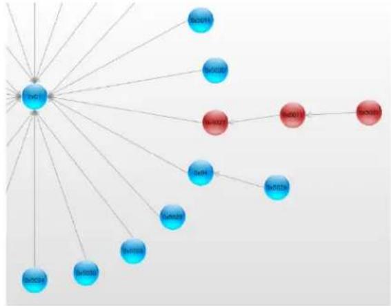
When the session starts, the network view becomes active and starts to populate the view. Each node joins with its parent and forms the network. It shows the hopping of the network immediately when it happens in the network. Also, when a node on the table is clicked, its corresponding node in this view turns orange and the user can zoom in/out or pan the diagram, when the network becomes huge.
Similar to the Table View, this view also actively reflects the node status as red or blue based on the node state.
Figure 10-15. Idle State Indication at Network View
flowchart
graph TD
    A["中心节点"] --> B["SociA"]
    A --> C["SociB"]
    A --> D["SociC"]
    A --> E["SociD"]
    A --> F["SociE"]
    A --> G["SociF"]
    A --> H["SociG"]
    A --> I["SociH"]
    A --> J["SociI"]
    A --> K["SociJ"]
    A --> L["SociK"]
    A --> M["SociL"]
    A --> N["SociM"]
    A --> O["SociN"]
    A --> P["SociO"]
10.2.4.1 Layout Type
The Topology View can be configured as two different layout types.
To set the layout type, navigate to Settings>Preferences>Network View.
Figure 10-16. Network View

text_image
Preferences Timing Network View Enable Client Notification blink Layout type Tree Radial Animate TransitionsLayout Type Setting
- Tree
It is the default layout view when the tool runs for the first time. It populates the view in a tree-like structure, as shown in the following figure.
Figure 10-17. Tree Layout View

flowchart
graph TD
    A["5=5020"] --> B["5=5016"]
    A --> C["5=5020"]
    C --> D["5=5020"]
    C --> E["5=5028"]
    C --> F["5=5028"]
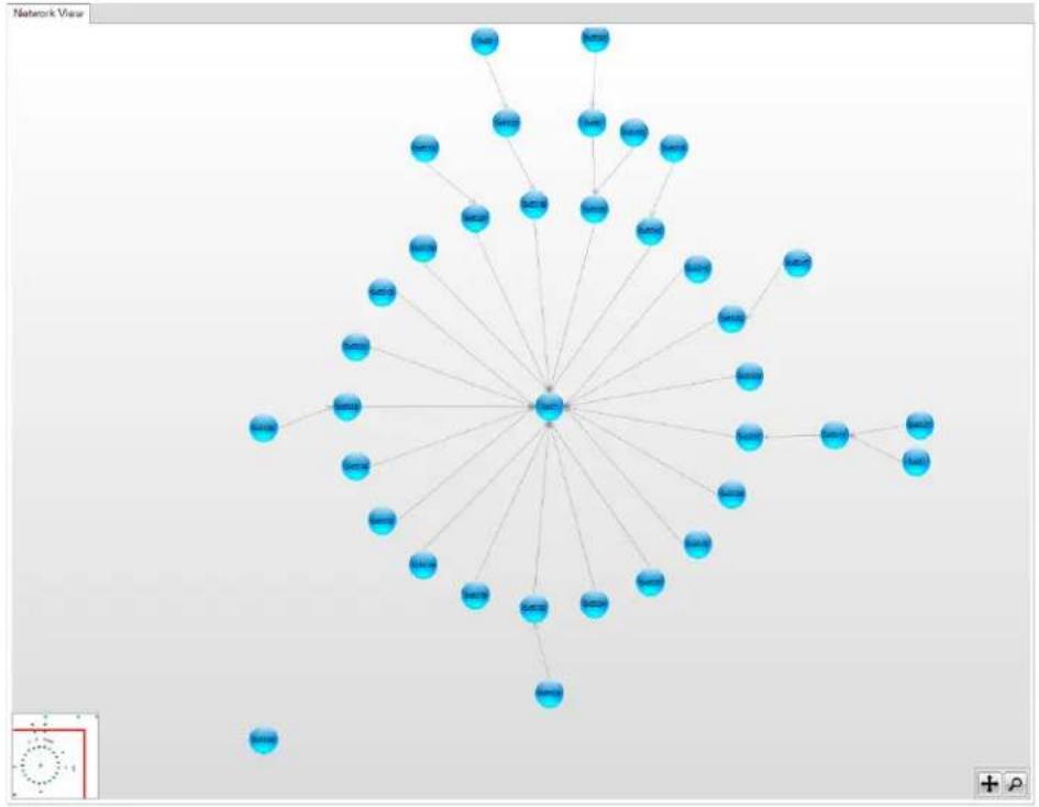
- Radial
It forms the nodes in a circular fashion, as shown in the following figure.
Figure 10-18. Radial Layout View
flowchart
graph TD
    A["Central Node"] --> B["Node 1"]
    A --> C["Node 2"]
    A --> D["Node 3"]
    A --> E["Node 4"]
    A --> F["Node 5"]
    A --> G["Node 6"]
    A --> H["Node 7"]
    A --> I["Node 8"]
    A --> J["Node 9"]
    A --> K["Node 10"]
    A --> L["Node 11"]
    A --> M["Node 12"]
    A --> N["Node 13"]
    A --> O["Node 14"]
    A --> P["Node 15"]
    A --> Q["Node 16"]
    A --> R["Node 17"]
    A --> S["Node 18"]
    A --> T["Node 19"]
    A --> U["Node 20"]
    A --> V["Node 21"]
    A --> W["Node 22"]
    A --> X["Node 23"]
    A --> Y["Node 24"]
    A --> Z["Node 25"]
    A --> AA["Node 26"]
    A --> AB["Node 27"]
    A --> AC["Node 28"]
    A --> AD["Node 29"]
    A --> AE["Node 30"]
    A --> AF["Node 31"]
    A --> AG["Node 32"]
    A --> AH["Node 33"]
    A --> AI["Node 34"]
    A --> AJ["Node 35"]
    A --> AK["Node 36"]
    A --> AL["Node 37"]
    A --> AM["Node 38"]
    A --> AN["Node 39"]
    A --> AO["Node 40"]
    A --> AP["Node 41"]
    A --> AQ["Node 42"]
    A --> AR["Node 43"]
    A --> AS["Node 44"]
    A --> AT["Node 45"]
    A --> AU["Node 46"]
    A --> AV["Node 47"]
    A --> AW["Node 48"]
    A --> AX["Node 49"]
    A --> AY["Node 50"]
10.2.5 Output View
The Output View is used to understand all the activities happening in the tool. It logs all the information that the user requested and provides its status or progress. All the success or failure messages can be seen using this view.
Figure 10-19. Output View
| Output | |
| 20:36:08 : WiDBG has started collecting data.. | |
| 20:36:08 : Getting server information... | |
| 20:36:08 : Server : 0x1122334455667788 has responded. | |
| 20:36:08 : Waiting for the client nodes from Channel-21 (0x15) | |
| 20:36:08 : Please wait... | |
| 20:36:10 : Node : 0x42500000001F1 has joined the network | |
| 20:36:11 : Node : 0x42500000001F2 has joined the network | |
| 20:36:11 : Node : 0x42500000001F4 has joined the network | |
| 20:36:11 : Node : 0x42500000001EF has joined the network | |
| 20:36:11 : Node : 0x42500000001EE has joined the network | |
| 20:36:12 : Node : 0x42500000001F3 has joined the network | |
| 20:36:12 : Node : 0x42500000001EB has joined the network | |
| 20:36:12 : Node : 0x42500000001F0 has joined the network | |
| 20:36:12 : Node : 0x42500000001ED has joined the network | |
| 20:36:12 : Node : 0x42500000001EC has joined the network | |
10.3 Upgrading the Node
A node can be upgraded using the Table View. To upgrade a node, perform the following steps.
- Right-click on the row and click Get Information as shown in the following screenshot. This provides the tool information about the firmware version which is currently running on the node.
Figure 10-20. Get the Firmware and Board Information

text_image
0x42500000001EF 0x1EF Router 0x4250000001EF 0x1EF Router 0x4250000000 0x4250000000 0x4250000000 0x4250000000 0x4250000000 0x1EF Router Identify Get Information DebugThe server node asks the client node about its version details and populates it on the respective columns.
- Click the Upgrade button of the corresponding node.
Figure 10-21. Upgrading the Respective Node

- Click the Browse button and select the HEX file from the list.
Details about the HEX file can be sent to the client using the following configuration. The same can be modified in otauClientInfoIndication_t clientInfo in client_notify.c of the client project to see the upgraded image information after upgrading.
Figure 10-22. Selecting the HEX File and Entering the Firmware Details

text_image
Select File and Upgrade Select Select the File for Upgrade Browse Enter Details about the File Firmware Your Stack Name Firmware version Your Stack version Board Atmel Board Name Board version Atmel Board Version OK CancelNote: The details about the HEX file on each field must not exceed the length of client_information sequence of the user_config.xml file.
- Click OK. The upgrade begins and progress bar starts to increase when the client receives the hex file data.
The upgrade data is sent to the client for every 1000 milliseconds by default.
To modify this interval, open the Preferences window from Settings menu and change the Client Response Interval under the Timing tab.
Figure 10-23. Setting the Client Response Interval to Upgrade
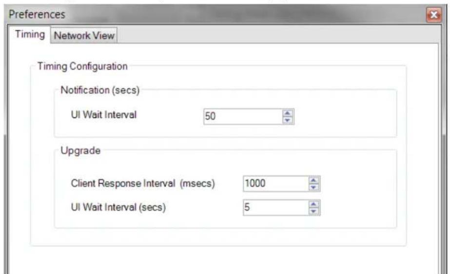
text_image
Preferences Timing Network View Timing Configuration Notification (secs) UI Wait Interval 50 Upgrade Client Response Interval (msecs) 1000 UI Wait Interval (secs) 5- If no response is received from the client, the tool stops the upgrade process after a predefined time period. This can be configured using the UI Wait Interval value in the Upgrade section of the Preferences window.
Figure 10-24. Setting the UI Wait Interval to Upgrade

text_image
Upgrade Client Response Interval (msecs) 1000 UI Wait Interval (secs) 5- When the full image is sent to the client, it is ready to switch the image as per the new image file. The user can switch to the new image as required.
Figure 10-25. Switching to a New Image

Click Switch to write into its Flash memory by the client and restarts as per the new image file selected during this process.
When the image is successfully switched, a pop-up notification about the upgrade status is displayed as shown in the following screenshot.
Figure 10-26. Upgrade Completed Status Window

text_image
Upgrade Status Upgrade Completed for Node 0x42500000001EF OK- Document Revision History
| Revision Date Section Description | |||
| B 06/2019 1.1 MiWi v6.3 Release | Content | Updated the title from 6.2 to 6.3. | |
| • Table 5-1• Figure 5-2 | Updated | ||
| • Table 7-1• Figure 7-3 | Updated | ||
| 8.4 Identifying Nodes Added a new paragraph. | |||
| A 02/2019 Document Initial Revision | |||
The Microchip Website
Microchip provides online support via our website at http://www.microchip.com/. This website is used to make files and information easily available to customers. Some of the content available includes:
- Product Support – Data sheets and errata, application notes and sample programs, design resources, user's guides and hardware support documents, latest software releases and archived software
- General Technical Support – Frequently Asked Questions (FAQs), technical support requests, online discussion groups, Microchip design partner program member listing
- Business of Microchip – Product selector and ordering guides, latest Microchip press releases, listing of seminars and events, listings of Microchip sales offices, distributors and factory representatives
Product Change Notification Service
Microchip's product change notification service helps keep customers current on Microchip products. Subscribers will receive email notification whenever there are changes, updates, revisions or errata related to a specified product family or development tool of interest.
To register, go to http://www.microchip.com/pcn and follow the registration instructions.
Customer Support
Users of Microchip products can receive assistance through several channels:
• Distributor or Representative
- Local Sales Office
• Embedded Solutions Engineer (ESE)
- Technical Support
Customers should contact their distributor, representative or ESE for support. Local sales offices are also available to help customers. A listing of sales offices and locations is included in this document.
Technical support is available through the web site at: http://www.microchip.com/support
Microchip Devices Code Protection Feature
Note the following details of the code protection feature on Microchip devices:
- Microchip products meet the specification contained in their particular Microchip Data Sheet.
- Microchip believes that its family of products is one of the most secure families of its kind on the market today, when used in the intended manner and under normal conditions.
- There are dishonest and possibly illegal methods used to breach the code protection feature. All of these methods, to our knowledge, require using the Microchip products in a manner outside the operating specifications contained in Microchip's Data Sheets. Most likely, the person doing so is engaged in theft of intellectual property.
- Microchip is willing to work with the customer who is concerned about the integrity of their code.
- Neither Microchip nor any other semiconductor manufacturer can guarantee the security of their code. Code protection does not mean that we are guaranteeing the product as “unbreakable.”
Code protection is constantly evolving. We at Microchip are committed to continuously improving the code protection features of our products. Attempts to break Microchip's code protection feature may be a violation of the Digital Millennium Copyright Act. If such acts allow unauthorized access to your software or other copyrighted work, you may have a right to sue for relief under that Act.
Legal Notice
Information contained in this publication regarding device applications and the like is provided only for your convenience and may be superseded by updates. It is your responsibility to ensure that your application meets with your specifications. MICROCHIP MAKES NO REPRESENTATIONS OR WARRANTIES OF ANY KIND WHETHER EXPRESS OR IMPLIED, WRITTEN OR ORAL, STATUTORY OR OTHERWISE, RELATED TO THE INFORMATION, INCLUDING BUT NOT LIMITED TO ITS CONDITION, QUALITY, PERFORMANCE, MERCHANTABILITY OR FITNESS FOR PURPOSE. Microchip disclaims all liability arising from this information and its use. Use of Microchip devices in life support and/or safety applications is entirely at the buyer's risk, and the buyer agrees to defend, indemnify and hold harmless Microchip from any and all damages, claims, suits, or expenses resulting from such use. No licenses are conveyed, implicitly or otherwise, under any Microchip intellectual property rights unless otherwise stated.
Trademarks
The Microchip name and logo, the Microchip logo, Adaptec, AnyRate, AVR, AVR logo, AVR Freaks, BesTime, BitCloud, chipKIT, chipKIT logo, CryptoMemory, CryptoRF, dsPIC, FlashFlex, flexPWR, HELDO, IGLOO, JukeBlox, KeeLoq, Kleer, LANCheck, LinkMD, maXStylus, maXTouch, MediaLB, megaAVR, Microsemi, Microsemi logo, MOST, MOST logo, MPLAB, OptoLyzer, PackeTime, PIC, picoPower, PICSTART, PIC32 logo, PolarFire, Prochip Designer, QTouch, SAM-BA, SenGenuity, SpyNIC, SST, SST Logo, SuperFlash, Symmetricom, SyncServer, Tachyon, TempTrackr, TimeSource, tinyAVR, UNI/O, Vectron, and XMEGA are registered trademarks of Microchip Technology Incorporated in the U.S.A. and other countries.
APT, ClockWorks, The Embedded Control Solutions Company, EtherSynch, FlashTec, Hyper Speed Control, HyperLight Load, IntelliMOS, Libero, motorBench, mTouch, Powermite 3, Precision Edge, ProASIC, ProASIC Plus, ProASIC Plus logo, Quiet-Wire, SmartFusion, SyncWorld, Temux, TimeCesium, TimeHub, TimePictra, TimeProvider, Vite, WinPath, and ZL are registered trademarks of Microchip Technology Incorporated in the U.S.A.
Adjacent Key Suppression, AKS, Analog-for-the-Digital Age, Any Capacitor, AnyIn, AnyOut, BlueSky, BodyCom, CodeGuard, CryptoAuthentication, CryptoAutomotive, CryptoCompanion, CryptoController, dsPICDEM, dsPICDEM.net, Dynamic Average Matching, DAM, ECAN, EtherGREEN, In-Circuit Serial Programming, ICSP, INICnet, Inter-Chip Connectivity, JitterBlocker, KleerNet, KleerNet logo, memBrain, Mindi, MiWi, MPASM, MPF, MPLAB Certified logo, MPLIB, MPLINK, MultiTRAK, NetDetach, Omniscient Code Generation, PICDEM, PICDEM.net, PICkit, PICtail, PowerSmart, PureSilicon, QMatrix, REAL ICE, Ripple Blocker, SAM-ICE, Serial Quad I/O, SMART-I.S., SQI, SuperSwitcher, SuperSwitcher II, Total Endurance, TSHARC, USBCheck, VariSense, ViewSpan, WiperLock, Wireless DNA, and ZENA are trademarks of Microchip Technology Incorporated in the U.S.A. and other countries.
SQTP is a service mark of Microchip Technology Incorporated in the U.S.A.
The Adaptec logo, Frequency on Demand, Silicon Storage Technology, and Symmcom are registered trademarks of Microchip Technology Inc. in other countries.
GestIC is a registered trademark of Microchip Technology Germany II GmbH & Co. KG, a subsidiary of Microchip Technology Inc., in other countries.
All other trademarks mentioned herein are property of their respective companies.
© 2019, Microchip Technology Incorporated, Printed in the U.S.A., All Rights Reserved.
ISBN: 978-1-5224-4594-4
Quality Management System
For information regarding Microchip's Quality Management Systems, please visit http://www.microchip.com/quality.
Worldwide Sales and Service
AMERICAS ASIA/PACIFIC ASIA/PACIFIC EUROPE
| Corporate Office | Australia - Sydney | India - Bangalore | Austria - Wels |
| 2355 West Chandler Blvd. | Tel: 61-2-9868-6733 | Tel: 91-80-3090-4444 | Tel: 43-7242-2244-39 |
| Chandler, AZ 85224-6199 | China - Beijing | India - New Delhi | Fax: 43-7242-2244-393 |
| Tel: 480-792-7200 | Tel: 86-10-8569-7000 | Tel: 91-11-4160-8631 | Denmark - Copenhagen |
| Fax: 480-792-7277 | China - Chengdu | India - Pune | Tel: 45-4450-2828 |
| Technical Support: | Tel: 86-28-8665-5511 | Tel: 91-20-4121-0141 | Fax: 45-4485-2829 |
| http://www.microchip.com/support | China - Chongqing | Japan - Osaka | Finland - Espoo |
| Web Address: | Tel: 86-23-8980-9588 | Tel: 81-6-6152-7160 | Tel: 358-9-4520-820 |
| http://www.microchip.com | China - Dongguan | Japan - Tokyo | France - Paris |
| Atlanta | Tel: 86-769-8702-9880 | Tel: 81-3-6880-3770 | Tel: 33-1-69-53-63-20 |
| Duluth, GA | China - Guangzhou | Korea - Daegu | Fax: 33-1-69-30-90-79 |
| Tel: 678-957-9614 | Tel: 86-20-8755-8029 | Tel: 82-53-744-4301 | Germany - Garching |
| Fax: 678-957-1455 | China - Hangzhou | Korea - Seoul | Tel: 49-8931-9700 |
| Austin, TX | Tel: 86-571-8792-8115 | Tel: 82-2-554-7200 | Germany - Haan |
| Tel: 512-257-3370 | China - Hong Kong SAR | Malaysia - Kuala Lumpur | Tel: 49-2129-3766400 |
| Boston | Tel: 852-2943-5100 | Tel: 60-3-7651-7906 | Germany - Heilbronn |
| Westborough, MA | China - Nanjing | Malaysia - Penang | Tel: 49-7131-72400 |
| Tel: 774-760-0087 | Tel: 86-25-8473-2460 | Tel: 60-4-227-8870 | Germany - Karlsruhe |
| Fax: 774-760-0088 | China - Qingdao | Philippines - Manila | Tel: 49-721-625370 |
| Chicago | Tel: 86-532-8502-7355 | Tel: 63-2-634-9065 | Germany - Munich |
| Itasca, IL | China - Shanghai | Singapore | Tel: 49-89-627-144-0 |
| Tel: 630-285-0071 | Tel: 86-21-3326-8000 | Tel: 65-6334-8870 | Fax: 49-89-627-144-44 |
| Fax: 630-285-0075 | China - Shenyang | Taiwan - Hsin Chu | Germany - Rosenheim |
| Dallas | Tel: 86-24-2334-2829 | Tel: 886-3-577-8366 | Tel: 49-8031-354-560 |
| Addison, TX | China - Shenzhen | Taiwan - Kaohsiung | Israel - Ra'anana |
| Tel: 972-818-7423 | Tel: 86-755-8864-2200 | Tel: 886-7-213-7830 | Tel: 972-9-744-7705 |
| Fax: 972-818-2924 | China - Suzhou | Taiwan - Taipei | Italy - Milan |
| Detroit | Tel: 86-186-6233-1526 | Tel: 886-2-2508-8600 | Tel: 39-0331-742611 |
| Novi, MI | China - Wuhan | Thailand - Bangkok | Fax: 39-0331-466781 |
| Tel: 248-848-4000 | Tel: 86-27-5980-5300 | Tel: 66-2-694-1351 | Italy - Padova |
| Houston, TX | China - Xian | Vietnam - Ho Chi Minh | Tel: 39-049-7625286 |
| Tel: 281-894-5983 | Tel: 86-29-8833-7252 | Tel: 84-28-5448-2100 | Netherlands - Drunen |
| Indianapolis | China - Xiamen | Tel: 31-416-690399 | |
| Noblesville, IN | Tel: 86-592-2388138 | Fax: 31-416-690340 | |
| Tel: 317-773-8323 | China - Zhuhai | Norway - Trondheim | |
| Fax: 317-773-5453 | Tel: 86-756-3210040 | Tel: 47-72884388 | |
| Tel: 317-536-2380 | Poland - Warsaw | ||
| Los Angeles | Tel: 48-22-3325737 | ||
| Mission Viejo, CA | Romania - Bucharest | ||
| Tel: 949-462-9523 | Tel: 40-21-407-87-50 | ||
| Fax: 949-462-9608 | Spain - Madrid | ||
| Tel: 951-273-7800 | Tel: 34-91-708-08-90 | ||
| Raleigh, NC | Fax: 34-91-708-08-91 | ||
| Tel: 919-844-7510 | Sweden - Gothenberg | ||
| New York, NY | Tel: 46-31-704-60-40 | ||
| Tel: 631-435-6000 | Sweden - Stockholm | ||
| San Jose, CA | Tel: 46-8-5090-4654 | ||
| Tel: 408-735-9110 | UK - Wokingham | ||
| Tel: 408-436-4270 | Tel: 44-118-921-5800 | ||
| Canada - Toronto | Fax: 44-118-921-5820 | ||
| Tel: 905-695-1980 | |||
| Fax: 905-695-2078 |