ATSAMD21G17L - Electronic component Microchip - Free user manual and instructions
Find the device manual for free ATSAMD21G17L Microchip in PDF.

User questions about ATSAMD21G17L Microchip
0 question about this device. Answer the ones you know or ask your own.
Ask a new question about this device
Download the instructions for your Electronic component in PDF format for free! Find your manual ATSAMD21G17L - Microchip and take your electronic device back in hand. On this page are published all the documents necessary for the use of your device. ATSAMD21G17L by Microchip.
USER MANUAL ATSAMD21G17L Microchip
ASF PROGRAMMERS MANUAL
Preface
The Atmel® Software Framework (ASF) is a collection of free embedded software for Atmel microcontroller devices. It simplifies the usage of Atmel products, providing an abstraction to the hardware and high-value middleware.
ASF is designed to be used for evaluation, prototyping, design and production phases. ASF is integrated in the Atmel Studio IDE with a graphical user interface or available as a standalone package for several commercial and open source compilers.
This document describes the API interfaces to the low level ASF module drivers of the device.

text_image
Your Code Applications SERVICES COMPONENTS DRIVERS UNITIES BOARDS [YOUR BOARD] ASFFor more information on ASF please refer to the online documentation at www.atmel.com/asf.
Table of Contents
Preface 1
Software License 13
- SAM D20/D21 Analog Comparator Driver (AC) 14
1.1. Prerequisites 14
1.2. Module Overview 14
1.2.1. Window Comparators and Comparator Pairs 14
1.2.2. Positive and Negative Input MUXs 14
1.2.3. Output Filtering 15
1.2.4.Input Hysteresis 15
1.2.5.Single Shot and Continuous Sampling Modes 15
1.2.6. Events 15
1.2.7. Physical Connection 15
1.3. Special Considerations 16
1.4. Extra Information 16
1.5. Examples 16
1.6. API Overview 16
1.6.1. Variable and Type Definitions 16
1.6.2. Structure Definitions 17
1.6.3. Macro Definitions 18
1.6.4. Function Definitions 20
1.6.5. Enumeration Definitions 29
1.7. Extra Information for AC Driver 32
1.7.1. Acronyms 32
1.7.2. Dependencies 33
1.7.3. Errata 33
1.7.4. Module History 33
1.8. Examples for AC Driver 33
1.8.1. Quick Start Guide for AC - Basic 33
1.8.2. Quick Start Guide for AC - Callback 37
- SAM D20/D21 Analog to Digital Converter Driver (ADC) 43
2.1. Prerequisites 43
2.2. Module Overview 43
2.2.1. Sample Clock Prescaler 44
2.2.2. ADC Resolution 44
2.2.3. Conversion Modes 44
2.2.4. Differential and Single-Ended Conversion 44
2.2.5. Sample Time 44
2.2.6.Averaging 45
2.2.7. Offset and Gain Correction 45
2.2.8. Pin Scan 46
2.2.9. Window Monitor 46
2.2.10. Events 46
2.3. Special Considerations 46
2.4. Extra Information 46
2.5. Examples 47
2.6. API Overview 47
2.6.1.Variable and Type Definitions 47
2.6.2. Structure Definitions 47
2.6.3. Macro Definitions 49
2.6.4. Function Definitions 50
2.6.5. Enumeration Definitions 62
2.7. Extra Information for ADC Driver 67
2.7.1. Acronyms 67
2.7.2. Dependencies 67
2.7.3. Errata 67
2.7.4. Module History 67
2.8. Examples for ADC Driver 67
2.8.1. Quick Start Guide for ADC - Basic 67
2.8.2. Quick Start Guide for ADC - Callback 70
2.8.3. Quick Start Guide for Using DMA with ADC/DAC 73
3. SAM D20/D21 Brown Out Detector Driver (BOD) 81
3.1. Prerequisites 81
3.2. Module Overview 81
3.3. Special Considerations 81
3.4. Extra Information 81
3.5. Examples 81
3.6. API Overview 81
3.6.1. Structure Definitions 81
3.6.2. Function Definitions 82
3.6.3. Enumeration Definitions 85
3.7. Extra Information for BOD Driver 86
3.7.1. Acronyms 86
3.7.2. Dependencies 86
3.7.3. Errata 86
3.7.4. Module History 86
3.8. Examples for BOD Driver 86
3.8.1. Quick Start Guide for BOD - Basic 86
3.8.2. Application Use Case for BOD - Application 88
4. SAM D20/D21 Digital-to-Analog Driver (DAC) 89
4.1. Prerequisites 89
4.2. Module Overview 89
4.2.1. Conversion Range 90
4.2.2. Conversion 90
4.2.3.Analog Output 90
4.2.4. Events 91
4.2.5. Left and Right Adjusted Values 91
4.2.6. Clock Sources 91
4.3. Special Considerations 91
4.3.1. Output Driver 91
4.3.2. Conversion Time 91
4.4. Extra Information 92
4.5. Examples 92
4.6. API Overview 92
4.6.1.Variable and Type Definitions 92
4.6.2. Structure Definitions 92
4.6.3. Macro Definitions 93
4.6.4. Function Definitions 93
4.6.5. Enumeration Definitions 106
4.7. Extra Information for DAC Driver 107
4.7.1. Acronyms 107
4.7.2. Dependencies 108
4.7.3. Errata 108
4.7.4. Module History 108
4.8. Examples for DAC Driver 108
4.8.1. Quick Start Guide for DAC - Basic 108
4.8.2. Quick Start Guide for DAC - Callback 111
4.8.3. Quick Start Guide for Using DMA with ADC/DAC 117
5. SAM D20/D21 EEPROM Emulator Service (EEPROM) ...... 118
5.1. Prerequisites 118
5.2. Module Overview 118
5.2.1. Implementation Details 118
5.2.2. Memory Layout 120
5.3. Special Considerations ...... 121
5.3.1. NVM Controller Configuration 121
5.3.2. Logical EEPROM Page Size 122
5.3.3. Committing of the Write Cache 122
5.4. Extra Information 122
5.5. Examples 122
5.6. API Overview 122
5.6.1. Structure Definitions 122
5.6.2. Macro Definitions 122
5.6.3. Function Definitions 123
5.7. Extra Information 127
5.7.1. Acronyms 127
5.7.2. Dependencies 127
5.7.3. Errata 128
5.7.4. Module History 128
5.8. Examples for Emulated EEPROM service 128
5.8.1. Quick Start Guide for the Emulated EEPROM module - Basic Use Case 128
6. SAM D20/D21 Event System Driver (EVENTS) 131
6.1. Prerequisites 131
6.2. Module Overview 131
6.2.1.Event Channels 132
6.2.2.Event Users 132
6.2.3. Edge Detection 132
6.2.4.Path Selection 132
6.2.5. Physical Connection 133
6.2.6.Configuring Events 134
6.3. Special Considerations 134
6.4. Extra Information 134
6.5. Examples 134
6.6. API Overview 134
6.6.1.Variable and Type Definitions 134
6.6.2. Structure Definitions 135
6.6.3. Macro Definitions 135
6.6.4. Function Definitions 135
6.6.5. Enumeration Definitions 14
6.7. Extra Information for EVENTS Driver 145
6.7.1. Acronyms 145
6.7.2. Dependencies 145
6.7.3. Errata 145
6.7.4. Module History 145
6.8. Examples for EVENTS Driver 145
6.8.1. Quick Start Guide for EVENTS - Basic 145
6.8.2. Quick Start Guide for EVENTS - interrupt hooks 148
7. SAM D20/D21 External Interrupt Driver (EXTINT) 153
7.1. Prerequisites 153
7.2. Module Overview 153
7.2.1. Logical Channels 153
7.2.2.NMI Channels 153
7.2.3. Input Filtering and Detection 153
7.2.4. Events and Interrupts 154
7.2.5. Physical Connection 154
7.3. Special Considerations 154
7.4. Extra Information 155
7.5. Examples 155
7.6. API Overview 155
7.6.1.Variable and Type Definitions 155
7.6.2. Structure Definitions 155
7.6.3. Macro Definitions 156
7.6.4. Function Definitions ...... 156
7.6.5. Enumeration Definitions 164
7.7. Extra Information for EXTINT Driver 165
7.7.1. Acronyms 165
7.7.2. Dependencies 165
7.7.3. Errata 165
7.7.4. Module History 165
7.8. Examples for EXTINT Driver 165
7.8.1. Quick Start Guide for EXTINT - Basic 166
7.8.2. Quick Start Guide for EXTINT - Callback 167
8. SAM D20/D21 I2C Driver (SERCOM I2C) 170
8.1. Prerequisites 170
8.2. Module Overview 170
8.2.1.Driver Feature Macro Definition 170
8.2.2. Functional Description 171
8.2.3. Bus Topology 171
8.2.4. Transactions 171
8.2.5.Multi Master 173
8.2.6. Bus States 173
8.2.7. Bus Timing 174
8.2.8. Operation in Sleep Modes 174
8.3. Special Considerations 175
8.3.1. Interrupt-Driven Operation 175
8.4. Extra Information 175
8.5. Examples 175
8.6. API Overview 175
8.6.1. Structure Definitions 175
8.6.2. Macro Definitions 177
8.6.3. Function Definitions 179
8.6.4. Enumeration Definitions 201
8.7. Extra Information for SERCOM I2C Driver 204
8.7.1. Acronyms 204
8.7.2. Dependencies 204
8.7.3. Errata 204
8.7.4. Module History 204
8.8. Examples for SERCOM I2C Driver 205
8.8.1. Quick Start Guide for SERCOM I2C Master - Basic 205
8.8.2. Quick Start Guide for SERCOM I2C Master - Callback ..... 208
8.8.3. Quick Start Guide for Using DMA with SERCOM I2C Master 211
8.8.4. Quick Start Guide for SERCOM I2C Slave - Basic 216
8.8.5. Quick Start Guide for SERCOM I2C Slave - Callback 218
8.8.6. Quick Start Guide for Using DMA with SERCOM I2C Slave .. 222
9. SAM D20/D21 Non-Volatile Memory Driver (NVM) 227
9.1. Prerequisites 227
9.2. Module Overview 227
9.2.1. Memory Regions 227
9.2.2. Region Lock Bits 228
9.2.3. Read/Write 229
9.3. Special Considerations 229
9.3.1.Page Erasure 229
9.3.2. Clocks 229
9.3.3. Security Bit 229
9.4. Extra Information 229
9.5. Examples 229
9.6. API Overview 229
9.6.1. Structure Definitions 229
9.6.2. Function Definitions 231
9.6.3. Enumeration Definitions 237
9.7. Extra Information for NVM Driver 241
9.7.1. Acronyms 241
9.7.2. Dependencies 241
9.7.3. Errata 241
9.7.4. Module History 241
9.8. Examples for NVM Driver 242
9.8.1. Quick Start Guide for NVM - Basic 242
10. SAM D20/D21 Peripheral Access Controller Driver (PAC) ..... 245
10.1. Prerequisites 245
10.2. Module Overview 245
10.2.1. Locking Scheme 245
10.2.2. Recommended Implementation 245
10.2.3. Why Disable Interrupts 246
10.2.4.Run-away Code 247
10.2.5. Faulty Module Pointer 249
10.2.6. Use of no inline 249
10.2.7. Physical Connection 249
10.3. Special Considerations 250
10.3.1. Non-Writable Registers 250
10.3.2. Reading Lock State 250
10.4. Extra Information 251
10.5. Examples 251
10.6. API Overview 251
10.6.1. Macro Definitions 251
10.6.2. Function Definitions 251
10.7. List of Non-Write Protected Registers 253
10.8. Extra Information for PAC Driver 254
10.8.1.Acronyms 254
10.8.2. Dependencies 254
10.8.3. Errata 254
10.8.4. Module History 254
10.9. Examples for PAC Driver 254
10.9.1. Quick Start Guide for PAC - Basic 254
11. SAM D20/D21 Port Driver (PORT) 258
11.1. Prerequisites 258
11.2. Module Overview 258
11.2.1. Physical and Logical GPIO Pins 258
11.2.2. Physical Connection 258
11.3. Special Considerations 259
11.4. Extra Information 259
11.5. Examples 259
11.6. API Overview 259
11.6.1. Structure Definitions 259
11.6.2. Macro Definitions 260
11.6.3. Function Definitions 260
11.6.4. Enumeration Definitions 265
11.7. Extra Information for PORT Driver 265
11.7.1. Acronyms 265
11.7.2. Dependencies 265
11.7.3. Errata 265
11.7.4. Module History 266
11.8. Examples for PORT Driver 266
11.8.1. Quick Start Guide for PORT - Basic 266
12. SAM D20/D21 RTC Calendar Driver (RTC CAL) 269
12.1. Prerequisites 269
12.2. Module Overview 269
12.2.1. Alarms and Overflow 269
12.2.2. Periodic Events 270
12.2.3. Digital Frequency Correction 270
12.3. Special Considerations 270
12.3.1.Year limit 270
12.3.2. Clock Setup 271
12.4. Extra Information 271
12.5. Examples 271
12.6. API Overview 271
12.6.1. Structure Definitions 271
12.6.2. Function Definitions 273
12.6.3. Enumeration Definitions 283
12.7. Extra Information for RTC (CAL) Driver 284
12.7.1. Acronyms 284
12.7.2. Dependencies 285
12.7.3. Errata 285
12.7.4. Module History 285
12.8. Examples for RTC CAL Driver 285
12.8.1. Quick Start Guide for RTC (CAL) - Basic 285
12.8.2. Quick Start Guide for RTC (CAL) - Callback 288
13. SAM D20/D21 RTC Count Driver (RTC COUNT) 293
13.1. Prerequisites 293
13.2. Module Overview 293
13.3. Compare and Overflow 293
13.3.1. Periodic Events 294
13.3.2. Digital Frequency Correction 294
13.4. Special Considerations 295
13.9. Examples for RTC (COUNT) Driver 309
13.9.1. Quick Start Guide for RTC (COUNT) - Basic 309
13.9.2. Quick Start Guide for RTC (COUNT) - Callback 312
14. SAM D20/D21 Serial Peripheral Interface Driver (SERCOM SPI) 316
14.1. Prerequisites 316
14.2. Module Overview 316
14.2.1.Driver Feature Macro Definition 316
14.2.2. SPI Bus Connection 316
14.2.3. SPI Character Size 317
14.2.4. Master Mode 317
14.2.5. Slave Mode 317
14.2.6. Data Modes 318
14.2.7.SERCOM Pads 318
14.2.8. Operation in Sleep Modes 318
14.2.9. Clock Generation 319
14.3. Special Considerations 319
14.3.1. Pin MUX Settings 319
14.4. Extra Information 319
14.5. Examples 319
14.6. API Overview 319
14.6.1. Variable and Type Definitions 319
14.6.2. Structure Definitions 319
14.6.3. Macro Definitions 321
14.6.4. Function Definitions 322
14.6.5. Enumeration Definitions 339
14.7. Mux Settings 341
14.7.1. Master Mode Settings 342
14.7.2. Slave Mode Settings 342
14.8. Extra Information for SERCOM SPI Driver 343
14.8.1. Acronyms 343
14.8.2. Dependencies 343
14.8.3. Workarounds Implemented by Driver 343
14.8.4. Module History 343
14.9. Examples for SERCOM SPI Driver 344
14.9.1. Quick Start Guide for SERCOM SPI Master - Polled 344
14.9.2. Quick Start Guide for SERCOM SPI Slave - Polled 348
14.9.3. Quick Start Guide for SERCOM SPI Master - Callback ..... 351
14.9.4. Quick Start Guide for SERCOM SPI Slave - Callback ..... 355
14.9.5. Quick Start Guide for Using DMA with SERCOM SPI 359
15. SAM D20/D21 Serial USART Driver (SERCOM USART) ...... 368
15.1. Prerequisites 368
15.2. Module Overview 368
15.2.1.Driver Feature Macro Definition 368
15.2.2.Frame Format 368
15.2.3. Synchronous mode 369
15.2.4. Asynchronous mode 369
15.2.5. Parity 369
15.2.6. GPIO configuration 370
15.3. Special Considerations 370
15.4. Extra Information 370
15.5. Examples 370
15.6. API Overview 370
15.6.1. Variable and Type Definitions 370
15.6.2. Structure Definitions 370
15.6.3. Macro Definitions 371
15.6.4. Function Definitions 372
15.6.5. Enumeration Definitions 383
15.7.SERCOM USART MUX Settings 385
15.8. Extra Information for SERCOM USART Driver 386
15.8.1. Acronyms 386
15.8.2. Dependencies 386
15.8.3. Errata 386
15.8.4. Module History 386
15.9. Examples for SERCOM USART Driver 387
15.9.1. Quick Start Guide for SERCOM USART - Basic 387
15.9.2. Quick Start Guide for SERCOM USART - Callback 390
15.9.3. Quick Start Guide for Using DMA with SERCOM USART ..... 393
16. SAM D20/D21 System Clock Management Driver (SYSTEM CLOCK) 400
16.1. Prerequisites 400
16.2. Module Overview 400
16.2.1.Driver Feature Macro Definition 400
16.2.2. Clock Sources 400
16.2.3. CPU / Bus Clocks 401
16.2.4. Clock Masking 401
16.2.5.GenericClocks 401
16.3. Special Considerations 403
16.4. Extra Information 403
16.5. Examples 403
16.6. API Overview 403
16.6.1. Structure Definitions 403
16.6.2. Function Definitions 406
16.6.3. Enumeration Definitions 421
16.7. Extra Information for SYSTEM CLOCK Driver 426
16.7.1. Acronyms 426
16.7.2. Dependencies 427
16.7.3. Errata 427
16.7.4. Module History 427
16.8. Examples for System Clock Driver 428
16.8.1. Quick Start Guide for SYSTEM CLOCK - Basic 428
16.8.2. Quick Start Guide for SYSTEM CLOCK - GCLK Configuration 431
17. SAM D20/D21 System Driver (SYSTEM) 434
17.1. Prerequisites 434
17.2. Module Overview 434
17.2.1. Voltage References 434
17.2.2. System Reset Cause 434
17.2.3.Sleep Modes 435
17.3. Special Considerations 435
17.4. Extra Information 435
17.5. Examples 435
17.6. API Overview 435
17.6.1. Function Definitions 435
17.6.2. Enumeration Definitions 438
17.7. Extra Information for SYSTEM Driver 439
17.7.1. Acronyms 439
17.7.2. Dependencies 439
17.7.3. Errata 439
17.7.4. Module History 439
18. SAM D20/D21 System Interrupt Driver (SYSTEM INTERRUPT) 440
18.1. Prerequisites 440
18.2. Module Overview 440
18.2.1. Critical Sections 440
18.2.2. Software Interrupts 440
18.3. Special Considerations 440
18.4. Extra Information 440
18.5. Examples 441
18.6. API Overview 441
18.6.1. Function Definitions 441
18.6.2. Enumeration Definitions 44:
18.7. Extra Information for SYSTEM INTERRUPT Driver 447
18.7.1. Acronyms 447
18.7.2. Dependencies 447
18.7.3. Errata 447
18.7.4. Module History 447
18.8. Examples for SYSTEM INTERRUPT Driver 448
18.8.1. Quick Start Guide for SYSTEM INTERRUPT - Critical Section Use Case 448
18.8.2. Quick Start Guide for SYSTEM INTERRUPT - Enable Module Interrupt Use Case 449
19. SAM D20/D21 System Pin Multiplexer Driver (SYSTEM PINMUX) 450
19.1. Prerequisites 450
19.2. Module Overview 450
19.2.1. Physical and Logical GPIO Pins 450
19.2.2. Peripheral Multiplexing 450
19.2.3. Special Pad Characteristics 450
19.2.4. Physical Connection 451
19.3. Special Considerations 451
19.4. Extra Information 451
19.5. Examples 451
19.6. API Overview 452
19.6.1. Structure Definitions 452
19.6.2. Macro Definitions 452
19.6.3. Function Definitions 452
19.6.4. Enumeration Definitions 455
19.7. Extra Information for SYSTEM PINMUX Driver 456
19.7.1. Acronyms 456
19.7.2. Dependencies 456
19.7.3. Errata 456
19.7.4. Module History 456
19.8. Examples for SYSTEM PINMUX Driver 456
19.8.1. Quick Start Guide for SYSTEM PINMUX - Basic 456
20. SAM D20/D21 Timer/Counter Driver (TC) 459
20.1. Prerequisites 459
20.2. Module Overview 459
20.2.1. Functional Description 460
20.2.2. Timer/Counter Size 460
20.2.3. Clock Settings 461
20.2.4. Compare Match Operations 462
20.2.5. One-shot Mode 464
20.3. Special Considerations 464
20.4. Extra Information 464
20.5. Examples 464
20.6. API Overview 464
20.6.1.Variable and Type Definitions 464
20.6.2. Structure Definitions 464
20.6.3. Macro Definitions 467
20.6.4. Function Definitions 468
20.6.5. Enumeration Definitions 476
20.7. Extra Information for TC Driver 479
20.7.1. Acronyms 479
20.7.2. Dependencies 479
20.7.3. Errata 479
20.7.4. Module History 479
20.8. Examples for TC Driver 479
20.8.1. Quick Start Guide for TC - Basic 480
20.8.2. Quick Start Guide for TC - Timer 482
20.8.3. Quick Start Guide for TC - Callback 485
20.8.4. Quick Start Guide for Using DMA with TC 488
21. SAM D20/D21 Watchdog Driver (WDT) 495
21.1. Prerequisites 495
21.2. Module Overview 495
21.2.1. Locked Mode 495
21.2.2. Window Mode 495
21.2.3. Early Warning 496
21.2.4. Physical Connection 496
21.3. Special Considerations 496
21.4. Extra Information 496
21.5. Examples 496
21.6. API Overview 496
21.6.1. Variable and Type Definitions 496
21.6.2. Structure Definitions 497
21.6.3. Function Definitions 497
21.6.4. Enumeration Definitions 501
21.7. Extra Information for WDT Driver 502
21.7.1. Acronyms 502
21.7.2. Dependencies 502
21.7.3. Errata 503
21.7.4. Module History 503
21.8. Examples for WDT Driver 503
21.8.1. Quick Start Guide for WDT - Basic 503
21.8.2. Quick Start Guide for WDT - Callback 505
22. SAM D21 Direct Memory Access Controller Driver (DMAC) .... 508
22.1. Prerequisites 508
22.2. Module Overview 508
22.2.1. Terminology Used in DMAC Transfers 509
22.2.2. DMA Channels 509
22.2.3. DMA Triggers 510
22.2.4. DMA Transfer Descriptor 510
22.2.5. DMA Interrupts/Events 510
22.3. Special Considerations 510
22.4. Extra Information 510
22.5. Examples 510
22.6. API Overview 510
22.6.1. Variable and Type Definitions 510
22.6.2. Structure Definitions 511
22.6.3. Macro Definitions 512
22.6.4. Function Definitions 513
22.6.5. Enumeration Definitions 520
22.7. Extra Information for DMAC Driver 522
22.7.1. Acronyms 522
22.7.2. Dependencies 523
22.7.3. Errata 523
22.7.4. Module History 523
22.8. Examples for DMAC Driver 523
22.8.1. Quick Start Guide for Memory to Memory 523
23. SAM D21 Inter-IC Sound Controller Driver (I2S) 528
23.1. Prerequisites 528
23.2. Module Overview 528
23.2.1. Clocks 529
23.2.2. Audio Frame Generation 529
23.2.3. Master, Controller and Slave modes 530
23.2.4. Data Stream Reception/Transmission 530
23.2.5. Loop-back Mode 533
23.2.6. Sleep Modes 533
23.3. Special Considerations 533
23.4. Extra Information 533
23.5. Examples 533
23.6. API Overview 534
23.6.1.Variable and Type Definitions 534
23.6.2. Structure Definitions 534
23.6.3. Macro Definitions 536
23.6.4. Function Definitions 537
23.6.5. Enumeration Definitions 551
23.7. Extra Information for I2S Driver 556
23.7.1. Acronyms 556
23.7.2. Dependencies 556
23.7.3. Errata 556
23.7.4. Module History 556
23.8. Examples for I2S Driver 556
23.8.1. Quick Start Guide for I2S - Basic 556
23.8.2. Quick Start Guide for I2S - Callback 561
23.8.3. Quick Start Guide for I2S - DMA 566
24. SAM D21 Timer Counter for Control Applications Driver (TCC) 576
24.1. Prerequisites 576
24.2. Module Overview 576
24.2.1. Functional Description 577
24.2.2. Base Timer/Counter 578
24.2.3. Capture Operations 579
24.2.4. Compare Match Operation 580
24.2.5. Waveform Extended Controls 581
24.2.6. Double and Circular Buffering 582
24.2.7. Sleep Mode 582
24.3. Special Considerations 582
24.3.1. Module Features 582
24.3.2. Channels VS. Pin outs 583
24.4. Extra Information 583
24.5. Examples 583
24.6. API Overview 583
24.6.1. Variable and Type Definitions 583
24.6.2. Structure Definitions 583
24.6.3. Macro Definitions 588
24.6.4. Function Definitions 591
24.6.5. Enumeration Definitions 607
24.7. Extra Information for TCC Driver 615
24.7.1. Acronyms 615
24.7.2. Dependencies 615
24.7.3. Errata 615
24.7.4. Module History 615
24.8. Examples for TCC Driver 616
24.8.1. Quick Start Guide for TCC - Basic 616
24.8.2. Quick Start Guide for TCC - Double Buffering & Circular ..... 619
24.8.3. Quick Start Guide for TCC - Timer 622
24.8.4. Quick Start Guide for TCC - Callback 625
24.8.5. Quick Start Guide for TCC - Non-Recoverable Fault 629
24.8.6. Quick Start Guide for TCC - Recoverable Fault 636
24.8.7. Quick Start Guide for Using DMA with TCC 643
25. SAM D21 Universal Serial Bus (USB) 653
25.1. USB Device Mode 653
25.2. USB Host Mode 653
Index 654
Document Revision History 662
Software License
Redistribution and use in source and binary forms, with or without modification, are permitted provided that the following conditions are met:
- Redistributions of source code must retain the above copyright notice, this list of conditions and the following disclaimer.
- Redistributions in binary form must reproduce the above copyright notice, this list of conditions and the following disclaimer in the documentation and/or other materials provided with the distribution.
- The name of Atmel may not be used to endorse or promote products derived from this software without specific prior written permission.
- This software may only be redistributed and used in connection with an Atmel microcontroller product.
THIS SOFTWARE IS PROVIDED BY ATMEL "AS IS" AND ANY EXPRESS OR IMPLIED WARRANTIES, INCLUDING, BUT NOT LIMITED TO, THE IMPLIED WARRANTIES OF MERCHANTABILITY, FITNESS FOR A PARTICULAR PURPOSE AND NON-INFRINGEMENT ARE EXPRESSLY AND SPECIFICALLY DISCLAIMED. IN NO EVENT SHALL ATMEL BE LIABLE FOR ANY DIRECT, INDIRECT, INCIDENTAL, SPECIAL, EXEMPLARY, OR CONSEQUENTIAL DAMAGES (INCLUDING, BUT NOT LIMITED TO, PROCUREMENT OF SUBSTITUTE GOODS OR SERVICES; LOSS OF USE, DATA, OR PROFITS; OR BUSINESS INTERRUPTION) HOWEVER CAUSED AND ON ANY THEORY OF LIABILITY, WHETHER IN CONTRACT, STRICT LIABILITY, OR TORT (INCLUDING NEGLIGENCE OR OTHERWISE) ARISING IN ANY WAY OUT OF THE USE OF THIS SOFTWARE, EVEN IF ADVISED OF THE POSSIBILITY OF SUCH DAMAGE.
1. SAM D20/D21 Analog Comparator Driver (AC)
This driver for SAM D20/D21 devices provides an interface for the configuration and management of the device's Analog Comparator functionality, for the comparison of analog voltages against a known reference voltage to determine its relative level. The following driver API modes are covered by this manual:
- Polled APIs
- Callback APIs
The following peripherals are used by this module:
• AC (Analog Comparator)
The outline of this documentation is as follows:
- Prerequisites
- Module Overview
• Special Considerations - Extra Information
- Examples
- API Overview
1.1 Prerequisites
There are no prerequisites for this module.
1.2 Module Overview
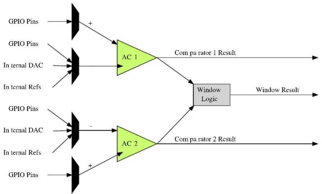
The Analog Comparator module provides an interface for the comparison of one or more analog voltage inputs (sourced from external or internal inputs) against a known reference voltage, to determine if the unknown voltage is higher or lower than the reference. Additionally, window functions are provided so that two comparators can be connected together to determine if an input is below, inside, above or outside the two reference points of the window.
Each comparator requires two analog input voltages, a positive and negative channel input. The result of the comparison is a binary true if the comparator's positive channel input is higher than the comparator's negative input channel, and false if otherwise.
1.2.1 Window Comparators and Comparator Pairs
Each comparator module contains one or more comparator pairs, a set of two distinct comparators which can be used independently or linked together for Window Comparator mode. In this latter mode, the two comparator units in a comparator pair are linked together to allow the module to detect if an input voltage is below, inside, above or outside a window set by the upper and lower threshold voltages set by the two comparators. If not required, window comparison mode can be turned off and the two comparator units can be configured and used separately.
1.2.2 Positive and Negative Input MUXs
Each comparator unit requires two input voltages, a positive and negative channel (note that these names refer to the logical operation that the unit performs, and both voltages should be above GND) which are then compared with one another. Both the positive and negative channel inputs are connected to a pair of MUXs, which allows one of several possible inputs to be selected for each comparator channel.
The exact channels available for each comparator differ for the positive and negative inputs, but the same MUX choices are available for all comparator units (i.e. all positive MUXes are identical, all negative MUXes are identical). This allows the user application to select which voltages are compared to one-another.
When used in window mode, both comparators in the window pair should have their positive channel input MUXs configured to the same input channel, with the negative channel input MUXs used to set the lower and upper window bounds.
1.2.3 Output Filtering
The output of each comparator unit can either be used directly with no filtering (giving a lower latency signal, with potentially more noise around the comparison threshold) or it can be passed through a multiple stage digital majority filter. Several filter lengths are available, with the longer stages producing a more stable result, at the expense of a higher latency.
When output filtering is used in single shot mode, a single trigger of the comparator will automatically perform the required number of samples to produce a correctly filtered result.
1.2.4 Input Hysteresis
To prevent unwanted noise around the threshold where the comparator unit's positive and negative input channels are close in voltage to one another, an optional hysteresis can be used to widen the point at which the output result flips. This mode will prevent a change in the comparison output unless the inputs cross one-another beyond the hysteresis gap introduces by this mode.
1.2.5 Single Shot and Continuous Sampling Modes
Comparators can be configured to run in either Single Shot or Continuous sampling modes; when in Single Shot mode, the comparator will only perform a comparison (and any resulting filtering, see Output Filtering) when triggered via a software or event trigger. This mode improves the power efficiency of the system by only performing comparisons when actually required by the application.
For systems requiring a lower latency or more frequent comparisons, continuous mode will place the comparator into continuous sampling mode, which increases the module's power consumption, but decreases the latency between each comparison result by automatically performing a comparison on every cycle of the module's clock.
1.2.6 Events
Each comparator unit is capable of being triggered by both software and hardware triggers. Hardware input events allow for other peripherals to automatically trigger a comparison on demand - for example, a timer output event could be used to trigger comparisons at a desired regular interval.
The module's output events can similarly be used to trigger other hardware modules each time a new comparison result is available. This scheme allows for reduced levels of CPU usage in an application and lowers the overall system response latency by directly triggering hardware peripherals from one another without requiring software intervention.
Note
The connection of events between modules requires the use of the SAM D20/D21 Event System Driver (EVENTS) to route output event of one module to the input event of another. For more information on event routing, refer to the event driver documentation.
1.2.7 Physical Connection
Physically, the modules are interconnected within the device as shown in Figure 1-1: Physical Connection on page 16.
Figure 1-1. Physical Connection
flowchart
graph LR
    A["GPIO Pins"] --> B["+"]
    C["GPIO Pins"] --> D["AC 1"]
    E["In ternal DAC"] --> D
    F["In ternal Refs"] --> D
    G["GPIO Pins"] --> H["+"]
    I["In ternal DAC"] --> H
    J["In ternal Refs"] --> H
    K["GPIO Pins"] --> L["+"]
    M["AC 2"] --> N["Window Logic"]
    O["Com pa rator 1 Result"] --> N
    P["Window Result"] --> N
    Q["Com pa rator 2 Result"] --> N
    B --> N
    D --> N
    H --> N
    L --> N
1.3 Special Considerations
The number of comparator pairs (and, thus, window comparators) within a single hardware instance of the Analog Comparator module is device-specific. Some devices will contain a single comparator pair, while others may have two pairs; refer to your device specific datasheet for details.
1.4 Extra Information
For extra information see Extra Information for AC Driver. This includes:
- Acronyms
- Dependencies
- Errata
- Module History
1.5 Examples
For a list of examples related to this driver, see Examples for AC Driver.
1.6 API Overview
1.6.1 Variable and Type Definitions
1.6.1.1 Type ac_callback_t
typedef void(* ac_callback_t )(struct ac_module *const module_inst)
Type definition for a AC module callback function.
1.6.2 Structure Definitions
1.6.2.1 Struct ac\_chan\_config
Configuration structure for a Comparator channel, to configure the input and output settings of the comparator.
Table 1-1. Members
| Type Name Description | ||
| bool enable_hysteresis When true, hysteresis mode is | enabled on the comparator inputs. | |
| enum ac_chan_filter filter Filtering mode for the comparator | output, when the comparator is used in a supported mode. | |
| enum ac_chan_interrupt_selection interrupt_selection Interrupt criteria for the comparator channel, to select the condition that will trigger a callback. | ||
| enum ac_chan_neg_mux negative_input Input multiplexer selection for the comparator's negative input pin. | ||
| enum ac_chan_output output_mode Output mode of the comparator, | whether it should be available for internal use, or asynchronously/ synchronously linked to a GPIO pin. | |
| enum ac_chan_pos_mux positive_input Input multiplexer selection for the comparator's positive input pin. | ||
| enum ac_chan_sample_mode | sample_mode | Sampling mode of the comparator channel. |
| uint8_t | vcc_scale_factor | Scaled VCC voltage division factor for the channel, when a comparator pin is connected to the VCC voltage scalar input. The formular is: Vscale = Vdd * vcc_scale_factor / 64. If the VCC voltage scalar is not selected as a comparator channel pin's input, this value will be ignored. |
1.6.2.2 Struct ac\_config
Configuration structure for a Comparator channel, to configure the input and output settings of the comparator.
Table 1-2. Members
| Type Name Description | ||
| bool run_in_standby[] | If true, the comparator pairs will | continue to sample during sleep mode when triggered. |
| enum gclk_generator | source_generator | Source generator for AC GCLK. |
1.6.2.3 Struct ac\_events
Event flags for the Analog Comparator module. This is used to enable and disable events via ac_enable_events() and ac_disable_events().
Table 1-3. Members
| Type Name Description | ||
| bool generate_event_on_state[] If true, an event will be generated | when a comparator state changes. | |
| bool generate_event_on_window[] If true, an event will be generated | when a comparator window state changes. | |
| bool on_event_sample[] If true, a comparator will be | sampled each time an event is received. | |
1.6.2.4 Struct ac\_module
AC software instance structure, used to retain software state information of an associated hardware module instance.
Note
The fields of this structure should not be altered by the user application; they are reserved for module-internal use only.
1.6.2.5 Struct ac\_win\_config
Table 1-4. Members
| Type Name Description | ||
| enum ac_win_interrupt_selection interrupt_selection Interrupt criteria for the | comparatorwindow channel, to select thecondition that will trigger acallback. | |
1.6.3 Macro Definitions
1.6.3.1 AC window channel status flags
AC window channel status flags, returned by ac_win_get_status().
Macro AC_WIN_STATUS_UNKNOWN
#define AC_WIN_STATUS_UNKNOWN (1UL << 0)
Unknown output state; the comparator window channel was not ready.
Macro AC_WIN_STATUS_ABOVE
#define AC_WIN_STATUS_ABOVE (1UL << 1)
Window Comparator's input voltage is above the window
Macro AC_WIN_STATUS_INSIDE
#define AC_WIN_STATUS_INSIDE (1UL << 2)
Window Comparator's input voltage is inside the window
Macro AC_WIN_STATUS_BELOW
#define AC_WIN_STATUS_BELOW (1UL << 3)
Window Comparator's input voltage is below the window
Macro AC_WIN_STATUS_INTERRUPT_SET
#define AC_WIN_STATUS_INTERRUPT_SET (1UL << 4)
This state reflects the window interrupt flag. When the interrupt flag should be set is configured in ac_win_set_config(). This state needs to be cleared by the of ac_win_clear_status().
1.6.3.2 AC channel status flags
AC channel status flags, returned by ac_chan_get_status().
Macro AC_CHAN_STATUS_UNKNOWN
#define AC_CHAN_STATUS_UNKNOWN (1UL << 0)
Unknown output state; the comparator channel was not ready.
Macro AC_CHAN_STATUS_NEG_ABOVE_POS
#define AC_CHAN_STATUS_NEG_ABOVE_POS (1UL << 1)
Comparator's negative input pin is higher in voltage than the positive input pin.
Macro AC_CHAN_STATUS_POS_ABOVE_NEG
#define AC_CHAN_STATUS_POS_ABOVE_NEG (1UL << 2)
Comparator's positive input pin is higher in voltage than the negative input pin.
Macro AC_CHAN_STATUS_INTERRUPT_SET
#define AC_CHAN_STATUS_INTERRUPT_SET (1UL << 3)
This state reflects the channel interrupt flag. When the interrupt flag should be set is configured in ac_chan_set_config(). This state needs to be cleared by the of ac_chan_clear_status().
1.6.4 Function Definitions
1.6.4.1 Configuration and Initialization
Function ac\_reset()
Resets and disables the Analog Comparator driver.
enum status_code ac_reset(
    struct ac_module *const module_inst)
Resets and disables the Analog Comparator driver, resets the internal states and registers of the hardware module to their power-on defaults.
Table 1-5. Parameters
| Data direction Parameter name Description | |
| [out] module_inst Pointer to the AC software instance | struct |
Function ac\_init()
Initializes and configures the Analog Comparator driver.
enum status_code ac_init(
    struct ac_module *const module_inst,
    Ac *const hw,
    struct ac_config *const config)
Initializes the Analog Comparator driver, configuring it to the user supplied configuration parameters, ready for use. This function should be called before enabling the Analog Comparator.
Note
Once called the Analog Comparator will not be running; to start the Analog Comparator call ac_enable() after configuring the module.
Table 1-6. Parameters
| Data direction Parameter name Description | |
| [out] module_inst Pointer to the AC software instance | struct |
| [in] hw Pointer to the AC module instance | |
| [in] config Pointer to the config struct, created | by the user application |
Function ac\_is\_syncing()
Determines if the hardware module(s) are currently synchronizing to the bus.
bool ac_is_syncing(
    struct ac_module *const module_inst)
Checks to see if the underlying hardware peripheral module(s) are currently synchronizing across multiple clock domains to the hardware bus. This function can be used to delay further operations on a module until such time that it is ready, to prevent blocking delays for synchronization in the user application.
Table 1-7. Parameters
| Data direction Parameter name Description | |
| [in] module_inst Pointer to the AC software instance | struct |
Returns
Synchronization status of the underlying hardware module(s).
Table 1-8. Return Values
| Return value Description | |
| true if the module has completed synchronization | |
| false if the module synchronization is ongoing |
Function ac\_get\_config\_defaults()
Initializes all members of an Analog Comparator configuration structure to safe defaults.
void ac_get_config_defaults(
    struct ac_config *const config)
Initializes all members of a given Analog Comparator configuration structure to safe known default values. This function should be called on all new instances of these configuration structures before being modified by the user application.
The default configuration is as follows:
- All comparator pairs disabled during sleep mode
- Generator 0 is the default GCLK generator
Table 1-9. Parameters
| Data direction Parameter name Description | |
| [out] config Configuration structure to initialize | to default values |
Function ac\_enable()
Enables an Analog Comparator that was previously configured.
void ac_enable(
    struct ac_module *const module_inst)
Enables an Analog Comparator that was previously configured via a call to ac_init().
Table 1-10. Parameters
| Data direction Parameter name Description | |
| [in] module_inst Software instance for the Analog | Comparator peripheral |
Function ac\_disable()
Disables an Analog Comparator that was previously enabled.
void ac_disable(
    struct ac_module *const module_inst)
Disables an Analog Comparator that was previously started via a call to ac_enable().
Table 1-11. Parameters
| Data direction Parameter name Description | |
| [in] module_inst Software instance for the Analog | Comparator peripheral |
Function ac\_enable\_events()
Enables an Analog Comparator event input or output.
void ac_enable_events(
    struct ac_module *const module_inst,
    struct ac_events *const events)
Enables one or more input or output events to or from the Analog Comparator module. See here for a list of events this module supports.
Note
Events cannot be altered while the module is enabled.
Table 1-12. Parameters
| Data direction Parameter name Description | |
| [in] module_inst Software instance for the Analog | Comparator peripheral |
| [in] events Struct containing flags of events to | enable |
Function ac\_disable\_events()
Disables an Analog Comparator event input or output.
void ac_disable_events(
    struct ac_module *const module_inst,
    struct ac_events *const events)
Disables one or more input or output events to or from the Analog Comparator module. See here for a list of events this module supports.
Note
Events cannot be altered while the module is enabled.
Table 1-13. Parameters
| Data direction Parameter name Description | |
| [in] module_inst Software instance for the Analog | Comparator peripheral |
| [in] events Struct containing flags of events to | disable |
1.6.4.2 Channel Configuration and Initialization
Function ac\_chan\_get\_config\_defaults()
Initializes all members of an Analog Comparator channel configuration structure to safe defaults.
void ac_chan_get_config_defaults(
    struct ac_chan_config *const config)
Initializes all members of an Analog Comparator channel configuration structure to safe defaults. This function should be called on all new instances of these configuration structures before being modified by the user application.
The default configuration is as follows:
• Continuous sampling mode
• Majority of 5 sample output filter
• Hysteresis enabled on the input pins
• Internal comparator output mode
- Comparator pin multiplexer 0 selected as the positive input
• Scaled VCC voltage selected as the negative input
• VCC voltage scaler set for a division factor of 2
- Channel interrupt set to occur when the compare threshold is passed
Table 1-14. Parameters
| Data direction Parameter name Description | |
| [out] config Channel configuration structure to | initialize to default values |
Function ac\_chan\_set\_config()
Writes an Analog Comparator channel configuration to the hardware module.
enum status_code ac_chan_set_config(
struct ac_module *const module_inst,
const enum ac_chan_channel channel, struct ac_chan_config *const config)
Writes a given Analog Comparator channel configuration to the hardware module.
Table 1-15. Parameters
| Data direction Parameter name Description | |
| [in] module_inst Software instance for the Analog | Comparator peripheral |
| [in] channel Analog Comparator channel to | configure |
| [in] config Pointer to the channel | configuration struct |
Function ac\_chan\_enable()
Enables an Analog Comparator channel that was previously configured.
void ac_chan_enable(
    struct ac_module *const module_inst,
    const enum ac_chan_channel channel)
Enables an Analog Comparator channel that was previously configured via a call to ac_chan_set_config().
Table 1-16. Parameters
| Data direction Parameter name Description | |
| [in] module_inst Software instance for the Analog | Comparator peripheral |
| [in] channel Comparator channel to enable |
Function ac\_chan\_disable()
Disables an Analog Comparator channel that was previously enabled.
void ac_chan_disable(
    struct ac_module *const module_inst,
    const enum ac_chan_channel channel)
Stops an Analog Comparator channel that was previously started via a call to ac_chan_enable().
Table 1-17. Parameters
| Data direction Parameter name Description | |
| [in] module_inst Software instance for the Analog | Comparator peripheral |
| [in] channel Comparator channel to disable |
1.6.4.3 Channel Control
Function ac_chan_trigger_single_shot()
Triggers a comparison on a comparator that is configured in single shot mode.
void ac_chan_trigger_single_shot(
    struct ac_module *const module_inst,
    const enum ac_chan_channel channel)
Triggers a single conversion on a comparator configured to compare on demand (single shot mode) rather than continuously.
Table 1-18. Parameters
| Data direction Parameter name Description | |
| [in] module_inst Software instance for the Analog | Comparator peripheral |
| [in] channel Comparator channel to trigger |
Function ac\_chan\_is\_ready()
Determines if a given comparator channel is ready for comparisons.
bool ac_chan_is_ready(
    struct ac_module *const module_inst,
    const enum ac_chan_channel channel)
Checks a comparator channel to see if the comparator is currently ready to begin comparisons.
Table 1-19. Parameters
| Data direction Parameter name Description | |
| [in] module_inst Software instance for the Analog | Comparator peripheral |
| [in] channel Comparator channel to test |
Returns
Comparator channel readiness state.
Function ac\_chan\_get\_status()
Determines the output state of a comparator channel.
uint8_t ac_chan_get_status(
    struct ac_module *const module_inst,
    const enum ac_chan_channel channel)
Retrieves the last comparison value (after filtering) of a given comparator. If the comparator was not ready at the time of the check, the comparison result will be indicated as being unknown.
Table 1-20. Parameters
| Data direction Parameter name Description | |
| [in] module_inst Software instance for the Analog | Comparator peripheral |
Data direction Parameter name Description
[in] channel Comparator channel to test
Returns
Bit mask of comparator channel status flags.
Function ac\_chan\_clear\_status()
Clears an interrupt status flag.
void ac_chan_clear_status(
    struct ac_module *const module_inst,
    const enum ac_chan_channel channel)
This function is used to clear the AC_CHAN_STATUS_INTERRUPT_SET flag it will clear the flag for the channel indicated by the channel argument
Table 1-21. Parameters
| Data direction Parameter name Description | |
| [in] module_inst Software instance for the Analog | Comparator peripheral |
| [in] channel Comparator channel to clear |
1.6.4.4 Window Mode Configuration and Initialization
Function ac\_win\_get\_config\_defaults()
Initializes an Analog Comparator window configuration structure to defaults.
void ac_win_get_config_defaults(
    struct ac_win_config *const config)
Initializes a given Analog Comparator channel configuration structure to a set of known default values. This function should be called if window interrupts are needed and before ac_win_set_config().
The default configuration is as follows:
- Channel interrupt set to occur when the measurement is above the window
Table 1-22. Parameters
| Data direction Parameter name Description | |
| [out] config Window configuration structure to | initialize to default values |
Function ac\_win\_set\_config()
Function used to setup interrupt selection of a window.
enum status_code ac_win_set_config(
    struct ac_module *const module_inst,
enum ac_win_channel const win_channel, struct ac_win_config *const config)
This function is used to setup when an interrupt should occur for a given window.
Note
This must be done before enabling the channel.
Table 1-23. Parameters
| Data direction Parameter name Description | |
| [in] module_inst Pointer to software instance struct | |
| [in] win_channel Window channel to setup | |
| [in] config Configuration for the given window | channel |
Table 1-24. Return Values
| Return value Description | |
| STATUS_OK Function exited successful | |
| STATUS_ERR_INVALID_ARG win_channel argument incorrect | |
Function ac\_win\_enable()
Enables an Analog Comparator window channel that was previously configured.
enum status_code ac_win_enable(
    struct ac_module *const module_inst,
    const enum ac_win_channel win_channel)
Enables and starts an Analog Comparator window channel.
Note
The comparator channels used by the window channel must be configured and enabled before calling this function. The two comparator channels forming each window comparator pair must have identical configurations other than the negative pin multiplexer setting.
Table 1-25. Parameters
| Data direction Parameter name Description | |
| [in] module_inst Software instance for the Analog | Comparator peripheral |
| [in] win_channel Comparator window channel to | enable |
Returns
Status of the window enable procedure.
Table 1-26. Return Values
| Return value Description | |
| STATUS_OK The window comparator was enabled | |
| STATUS_ERR_IO One or both comparators in the window comparatorpair is disabled | |
| STATUS_ERR_BAD_FORMAT The comparator channels in the window pair were notconfigured correctly | |
Function ac\_win\_disable()
Disables an Analog Comparator window channel that was previously enabled.
void ac_win_disable(
    struct ac_module *const module_inst,
    const enum ac_win_channel win_channel)
Stops an Analog Comparator window channel that was previously started via a call to ac_win_enable().
Table 1-27. Parameters
| Data direction Parameter name Description | |
| [in] module_inst Software instance for the Analog | Comparator peripheral |
| [in] win_channel Comparator window channel to | disable |
1.6.4.5 Window Mode Control
Function ac\_win\_is\_ready()
Determines if a given Window Comparator is ready for comparisons.
bool ac_win_is_ready(
    struct ac_module *const module_inst,
    const enum ac_win_channel win_channel)
Checks a Window Comparator to see if the both comparators used for window detection is currently ready to begin comparisons.
Table 1-28. Parameters
| Data direction Parameter name Description | |
| [in] module_inst Software instance for the Analog | Comparator peripheral |
| [in] win_channel Window Comparator channel to | test |
Returns
Window Comparator channel readiness state.
Function ac\_win\_get\_status()
Determines the state of a specified Window Comparator.
uint8_t ac_win_get_status(
    struct ac_module *const module_inst,
    const enum ac_win_channel win_channel)
Retrieves the current window detection state, indicating what the input signal is currently comparing to relative to the window boundaries.
Table 1-29. Parameters
| Data direction Parameter name Description | |
| [in] module_inst Software instance for the Analog | Comparator peripheral |
| [in] win_channel Comparator Window channel to | test |
Returns
Bit mask of Analog Comparator window channel status flags
Function ac\_win\_clear\_status()
Clears an interrupt status flag.
void ac_win_clear_status(
    struct ac_module *const module_inst,
    const enum ac_win_channel win_channel)
This function is used to clear the AC_WIN_STATUS_INTERRUPT_SET flag it will clear the flag for the channel indicated by the win_channel argument
Table 1-30. Parameters
| Data direction Parameter name Description | |
| [in] module_inst Software instance for the Analog | Comparator peripheral |
| [in] win_channel Window channel to clear |
1.6.5 Enumeration Definitions
1.6.5.1 Enum ac_callback
Enum for possible callback types for the AC module
Table 1-31. Members
| Enum value Description | |
| AC_CALLBACKComparator_0 Callback for comparator 0 | |
| AC_CALLBACKComparator_1 Callback for comparator 1 | |
| AC_CALLBACK_WINDOW_0 Callback for window 0 |
1.6.5.2 Enum ac_chan_channel
Enum for the possible comparator channels.
Table 1-32. Members
| Enum value Description | |
| AC_CHAN_CHANNEL_0 Comparator channel 0 (Pair 0, Comparator 0) | |
| AC_CHAN_CHANNEL_1 Comparator channel 1 (Pair 0, Comparator 1) | |
| AC_CHAN_CHANNEL_2 Comparator channel 2 (Pair 1, Comparator 0) | |
| AC_CHAN_CHANNEL_3 Comparator channel 3 (Pair 1, Comparator 1) | |
1.6.5.3 Enum ac\_chan\_filter
Enum for the possible channel output filtering configurations of an Analog Comparator channel.
Table 1-33. Members
| Enum value Description | |
| AC_CHAN_FILTER_NONE No output filtering is performed on the comparator channel. | |
| AC_CHAN_FILTER_MAJORITY_3 Comparator channel output is passed through a Majority-of-Three filter. | |
| AC_CHAN_FILTER_MAJORITY_5 Comparator channel output is passed through a Majority-of-Five filter. | |
1.6.5.4 Enum ac\_chan\_interrupt\_selection
This enum is used to select when a channel interrupt should occur.
Table 1-34. Members
| Enum value Description | |
| AC_CHAN_INTERRUPT_SELECTION_TOGGLE An interrupt will be generated when the comparator level is passed | |
| AC_CHAN_INTERRUPT_SELECTION_RISING An interrupt will be generated when the measurement goes above the compare level | |
| AC_CHAN_INTERRUPT_SELECTION_FALLING An interrupt will be generated when the measurement goes below the compare level | |
| AC_CHAN_INTERRUPT_SELECTION_END_OF_COMPARE An interrupt will be generated when a new measurement is complete. Interrupts will only be generated in single shot mode. This state needs to be cleared by the use of ac_chan_cleare_status(). | |
1.6.5.5 Enum ac\_chan\_neg\_mux
Enum for the possible channel negative pin input of an Analog Comparator channel.
Table 1-35. Members
| Enum value Description | |
| AC_CHAN_NEG_MUX_PIN0 Negative comparator input is connected to physical AC input pin 0. | |
| AC_CHAN_NEG_MUX_PIN1 Negative comparator input is connected to physical AC input pin 1. | |
| AC_CHAN_NEG_MUX_PIN2 Negative comparator input is connected to physical AC input pin 2. | |
| AC_CHAN_NEG_MUX_PIN3 Negative comparator input is connected to physical AC input pin 3. | |
| AC_CHAN_NEG_MUX_GND Negative comparator input is connected to the internal ground plane. | |
| AC_CHAN_NEG_MUX_SCALED_VCC Negative comparator input is connected to the channel's internal VCC plane voltage scalar. | |
| AC_CHAN_NEG_MUX_BANDGAP Negative comparator input is connected to the internal band gap voltage reference. | |
| AC_CHAN_NEG_MUX_DAC0 Negative comparator input is connected to the channel's internal DAC channel 0 output. | |
1.6.5.6 Enum ac\_chan\_output
Enum for the possible channel GPIO output routing configurations of an Analog Comparator channel.
Table 1-36. Members
| Enum value Description | |
| AC_CHAN_OUTPUT_INTERNAL Comparator channel output is not routed to a physical GPIO pin, and is used internally only. | |
| AC_CHAN_OUTPUT_ASYNCRONOUS Comparator channel output is routed to its matching physical GPIO pin, via an asynchronous path. | |
| AC_CHAN_OUTPUT_SYNCHRONOUS Comparator channel output is routed to its matching physical GPIO pin, via a synchronous path. | |
1.6.5.7 Enum ac\_chan\_pos\_mux
Enum for the possible channel positive pin input of an Analog Comparator channel.
Table 1-37. Members
| Enum value Description | |
| AC_CHAN_POS_MUX_PIN0 Positive comparator input is connected to physical AC input pin 0. | |
| AC_CHAN_POS_MUX_PIN1 Positive comparator input is connected to physical AC input pin 1. | |
| AC_CHAN_POS_MUX_PIN2 Positive comparator input is connected to physical AC input pin 2. | |
| AC_CHAN_POS_MUX_PIN3 Positive comparator input is connected to physical AC input pin 3. | |
1.6.5.8 Enum ac\_chan\_sample\_mode
Enum for the possible channel sampling modes of an Analog Comparator channel.
Table 1-38. Members
| Enum value Description | |
| AC_CHAN_MODE_CONTINUOUS Continuous sampling mode; when the channel is enabled the comparator output is available for reading at any time. | |
| AC_CHAN_MODE_SINGLE_SHOT Single shot mode; when used the comparator channel must be triggered to perform a comparison before reading the result. | |
1.6.5.9 Enum ac\_win\_channel
Enum for the possible window comparator channels.
Table 1-39. Members
| Enum value Description | |
| AC_WIN_CHANNEL_0 Window channel 0 (Pair 0, Comparators 0 and 1) | |
| AC_WIN_CHANNEL_1 Window channel 1 (Pair 1, Comparators 2 and 3) |
1.6.5.10 Enum ac\_win\_interrupt\_selection
This enum is used to select when a window interrupt should occur.
Table 1-40. Members
| Enum value Description | |
| AC_WIN_INTERRUPT_SELECTION_ABOVE Interrupt is generated when the compare value goes above the window | |
| AC_WIN_INTERRUPT_SELECTION_INSIDE Interrupt is generated when the compare value goes inside the window | |
| AC_WIN_INTERRUPT_SELECTION_BELOW Interrupt is generated when the compare value goes below the window | |
| AC_WIN_INTERRUPT_SELECTION_OUTSIDE Interrupt is generated when the compare value goes outside the window | |
1.7 Extra Information for AC Driver
1.7.1 Acronyms
Below is a table listing the acronyms used in this module, along with their intended meanings.
| Acronym Description | |
| AC Analog Comparator | |
| DAC Digital-to-Analog Converter | |
| MUX | Multiplexer |
1.7.2 Dependencies
This driver has the following dependencies:
• System Pin Multiplexer Driver
1.7.3 Errata
There are no errata related to this driver.
1.7.4 Module History
An overview of the module history is presented in the table below, with details on the enhancements and fixes made to the module since its first release. The current version of this corresponds to the newest version in the table.
Changelog
Added support for SAMD21
Initial Release
1.8 Examples for AC Driver
This is a list of the available Quick Start guides (QSGs) and example applications for SAM D20/D21 Analog Comparator Driver (AC). QSGs are simple examples with step-by-step instructions to configure and use this driver in a selection of use cases. Note that QSGs can be compiled as a standalone application or be added to the user application.
- Quick Start Guide for AC - Basic
- Quick Start Guide for AC - Callback
1.8.1 Quick Start Guide for AC - Basic
In this use case, the Analog Comparator module is configured for:
- Comparator peripheral in manually triggered (i.e. "Single Shot" mode)
- One comparator channel connected to input MUX pin 0 and compared to a scaled VCC/2 voltage
This use case sets up the Analog Comparator to compare an input voltage fed into a GPIO pin of the device against a scaled voltage of the microcontroller's VCC power rail. The comparisons are made on-demand in single-shot mode, and the result stored into a local variable which is then output to the board LED to visually show the comparison state.
1.8.1.1 Setup
Prerequisites
There are no special setup requirements for this use-case.
Code
Copy-paste the following setup code to your user application:
/* AC module software instance (must not go out of scope while in use) */
static struct ac_module ac_instance;

/* Comparator channel that will be used */
#define AC_COMPARATOR_CHANNEL AC_CHAN_CHANNEL_0
void configure_ac(void)
{
    /* Create a new configuration structure for the Analog Comparator settings
    * and fill with the default module settings. */
    struct ac_config config_ac;
    ac_get_config_defaults(&config_ac);

    /* Alter any Analog Comparator configuration settings here if required */
    /* Initialize and enable the Analog Comparator with the user settings */
    ac_init(&ac_instance, AC, &config_ac);
}

void configure_ac_channel(void)
{
    /* Create a new configuration structure for the Analog Comparator channel
    * settings and fill with the default module channel settings. */
    struct ac_chan_config ac_chan_conf;
    ac_chan_get_config_defaults(&ac_chan_conf);

    /* Set the Analog Comparator channel configuration settings */
    ac_chan_conf.sample_mode = AC_CHAN_MODE_SINGLE_SHOT;
    ac_chan_conf.positive_input = AC_CHAN_POS_MUX_PIN0;
    ac_chan_conf.negative_input = AC_CHAN_NEG_MUX_SCALED_VCC;
    ac_chan_conf.vcc_scale_factor = 32;

    /* Set up a pin as an AC channel input */
    struct system_pinmux_config ac0_pin_conf;
    system_pinmux_get_config_defaults(&ac0_pin_conf);
    ac0_pin_conf.direction = SYSTEM_PINMUX_PIN_DIR_INPUT;
    ac0_pin_conf.mux_position = MUX_PA04B_AC_AINO;
    system_pinmux_pin_set_config(PIN_PA04B_AC_AINO, &ac0_pin_conf);

    /* Initialize and enable the Analog Comparator channel with the user
    * settings */
    ac_chan_set_config(&ac_instance, AC_COMPARATOR_CHANNEL, &ac_chan_conf);
    ac_chan_enable(&ac_instance, AC_COMPARATOR_CHANNEL);
}
Add to user application initialization (typically the start of main()):
system_init();
configure_ac();
configure_ac_channel();
ac_enable(&ac_instance);
Workflow
- Create an AC device instance struct, which will be associated with an Analog Comparator peripheral hardware instance.
static struct ac_module ac_instance;
Note
Device instance structures shall never go out of scope when in use.
- Define a macro to select the comparator channel that will be sampled, for convenience.
#define AC_COMPARATOR_CHANNEL AC_CHAN_CHANNEL_0
- Create a new function configure_ac(), which will be used to configure the overall Analog Comparator peripheral.
void configure_ac(void)
- Create an Analog Comparator peripheral configuration structure that will be filled out to set the module configuration.
struct ac_config config_ac;
- Fill the Analog Comparator peripheral configuration structure with the default module configuration values.
ac_get_config_defaults(&config_ac);
- Initialize the Analog Comparator peripheral and associate it with the software instance structure that was defined previously.
ac_init(&ac_instance, AC, &config_ac);
- Create a new function configure_ac_channel(), which will be used to configure the overall Analog Comparator peripheral.
void configure_ac_channel(void)
- Create an Analog Comparator channel configuration structure that will be filled out to set the channel configuration.
struct ac_chan_config ac_chan_conf;
- Fill the Analog Comparator channel configuration structure with the default channel configuration values.
ac_chan_get_config_defaults(&ac_chan_conf);
- Alter the channel configuration parameters to set the channel to one-shot mode, with the correct negative and positive MUX selections and the desired voltage scaler.
ac_chan_conf.sample_mode = AC_CHAN_MODE_SINGLE_SHOT;
ac_chan_conf.positive_input = AC_CHAN_POS_MUX_PIN0;
ac_chan_conf.negative_input = AC_CHAN_NEG_MUX_SCALED_VCC;
ac_chan_conf.vcc_scale_factor = 32;
Note
The voltage scalar formula is documented in description for ac_chan_config::vcc_scale_factor.
- Configure the physical pin that will be routed to the AC module channel 0.
struct system_pinmux_config ac0_pin_conf;
system_pinmux_get_config_defaults(&ac0_pin_conf);
ac0_pin_conf.direction = SYSTEM_PINMUX_PIN_DIR_INPUT;
ac0_pin_conf.mux_position = MUX_PA04B_AC_AINO;
system_pinmux_pin_set_config(PIN_PA04B_AC_AINO, &ac0_pin_conf);
- Initialize the Analog Comparator channel and configure it with the desired settings.
ac_chan_set_config(&ac_instance, AC_COMPARATOR_CHANNEL, &ac_chan_conf);
- Enable the now initialized Analog Comparator channel.
ac_chan_enable(&ac_instance, AC_COMPARATOR_CHANNEL);
- Enable the now initialized Analog Comparator peripheral.
ac_enable(&ac_instance);
1.8.1.2 Implementation
Code
Copy-paste the following code to your user application:
ac_chan_trigger_single_shot(&ac_instance, AC_COMPARATOR_CHANNEL);
uint8_t last_comparison = AC_CHAN_STATUS_UNKNOWN;
while (true) {
    if (ac_chan_is_ready(&ac_instance, AC_COMPARATOR_CHANNEL)) {
    do {
    last_comparison = ac_chan_get_status(&ac_instance, AC_COMPARATOR_CHANNEL);
    } while (last_comparison & AC_CHAN_STATUS_UNKNOWN);

    port_pin_set_output_level(LED_0_PIN,
    (last_comparison & AC_CHAN_STATUS_NEG_ABOVE_POS));

    ac_chan_trigger_single_shot(&ac_instance, AC_COMPARATOR_CHANNEL);
    }
}
Workflow
- Trigger the first comparison on the comparator channel.
ac_chan_trigger_single_shot(&ac_instance, AC_COMPARATOR_CHANNEL);
- Create a local variable to maintain the current comparator state. Since no comparison has taken place, it is initialized to AC_CHAN_STATUS_UNKNOWN.
uint8_t last_comparison = AC_CHAN_STATUS_UNKNOWN;
- Make the application loop infinitely, while performing triggered comparisons.
while (true) {
- Check if the comparator is ready for the last triggered comparison result to be read.
if (ac_chan_is_ready(&ac_instance, AC_COMPARATOR_CHANNEL)) {
- Read the comparator output state into the local variable for application use, re-trying until the comparison state is ready.
do {
    last_comparison = ac_chan_get_status(&ac_instance, AC_COMPARATOR_CHANNEL);
} while (last_comparison & AC_CHAN_STATUS_UNKNOWN);
- Set the board LED state to mirror the last comparison state.
port_pin_set_output_level(LED_0_PIN, (last_comparison & AC_CHAN_STATUS_NEG_ABOVE_POS));
- Trigger the next conversion on the Analog Comparator channel.
ac_chan_trigger_single_shot(&ac_instance, AC_COMPARATOR_CHANNEL);
1.8.2 Quick Start Guide for AC - Callback
In this use case, the Analog Comparator module is configured for:
- Comparator peripheral in manually triggered (i.e. "Single Shot" mode)
• One comparator channel connected to input MUX pin 0 and compared to a scaled VCC/2 voltage
This use case sets up the Analog Comparator to compare an input voltage fed into a GPIO pin of the device against a scaled voltage of the microcontroller's VCC power rail. The comparisons are made on-demand in single-shot mode, and the result stored into a local variable which is then output to the board LED to visually show the comparison state.
1.8.2.1 Setup
Prerequisites
There are no special setup requirements for this use-case.
Code
Copy-paste the following setup code to your user application:
/* AC module software instance (must not go out of scope while in use) */
static struct ac_module ac_instance;

/* Comparator channel that will be used */
#define AC_COMPARATOR_CHANNEL AC_CHAN_CHANNEL_0

void configure_ac(void)
{
    /* Create a new configuration structure for the Analog Comparator settings
    * and fill with the default module settings. */
    struct ac_config config_ac;
    ac_get_config_defaults(&config_ac);

    /* Alter any Analog Comparator configuration settings here if required */
/* Initialize and enable the Analog Comparator with the user settings */
ac_init(&ac_instance, AC, &config_ac);
}

void configure_ac_channel(void)
{
    /* Create a new configuration structure for the Analog Comparator channel
    * settings and fill with the default module channel settings. */
    struct ac_chan_config config_ac_chan;
    ac_chan_get_config_defaults(&config_ac_chan);

    /* Set the Analog Comparator channel configuration settings */
    config_ac_chan.sample_mode = AC_CHAN_MODE_SINGLE_SHOT;
    config_ac_chan.positive_input = AC_CHAN_POS_MUX_PIN0;
    config_ac_chan.negative_input = AC_CHAN_NEG_MUX_SCALED_VCC;
    config_ac_chan.vcc_scale_factor = 32;
    config_ac_chan.interrupt_selection = AC_CHAN_INTERRUPT_SELECTION_END_OF_COMPARE;

    /* Set up a pin as an AC channel input */
    struct system_pinmux_config ac0_pin_conf;
    system_pinmux_get_config_defaults(&ac0_pin_conf);
    ac0_pin_conf.direction = SYSTEM_PINMUX_PIN_DIR_INPUT;
    ac0_pin_conf.mux_position = MUX_PA04B_AC_AINO;
    system_pinmux_pin_set_config(PIN_PA04B_AC_AINO, &ac0_pin_conf);

    /* Initialize and enable the Analog Comparator channel with the user
    * settings */
    ac_chan_set_config(&ac_instance, AC_COMPARATOR_CHANNEL, &config_ac_chan);
    ac_chan_enable(&ac_instance, AC_COMPARATOR_CHANNEL);
}

void callback_function_ac(struct ac_module *const module_inst)
{
    callback_status = true;
}

void configure_ac_callback(void)
{
    ac_register_callback(&ac_instance, callback_function_ac, AC_CALLBACK_COMPARATOR_0);
    ac_enable_callback(&ac_instance, AC_CALLBACK_COMPARATOR_0);
}
Add to user application initialization (typically the start of main():
system_init();
configure_ac();
configure_ac_channel();
configure_ac_callback();
ac_enable(&ac_instance);
Workflow
- Create an AC device instance struct, which will be associated with an Analog Comparator peripheral hardware instance.
static struct ac_module ac_instance;
Note
Device instance structures shall never go out of scope when in use.
- Define a macro to select the comparator channel that will be sampled, for convenience.
#define AC_COMPARATOR_CHANNEL AC_CHAN_CHANNEL_0
- Create a new function configure_ac(), which will be used to configure the overall Analog Comparator peripheral.
void configure_ac(void)
{
- Create an Analog Comparator peripheral configuration structure that will be filled out to set the module configuration.
struct ac_config config_ac;
- Fill the Analog Comparator peripheral configuration structure with the default module configuration values.
ac_get_config_defaults(&config_ac);
- Initialize the Analog Comparator peripheral and associate it with the software instance structure that was defined previously.
ac_init(&ac_instance, AC, &config_ac);
- Create a new function configure_ac_channel(), which will be used to configure the overall Analog Comparator peripheral.
void configure_ac_channel(void)
{
- Create an Analog Comparator channel configuration structure that will be filled out to set the channel configuration.
struct ac_chan_config config_ac_chan;
- Fill the Analog Comparator channel configuration structure with the default channel configuration values.
ac_chan_get_config_defaults(&config_ac_chan);
- Alter the channel configuration parameters to set the channel to one-shot mode, with the correct negative and positive MUX selections and the desired voltage scaler.
Note
The voltage scalar formula is documented in description for ac_chan_config::vcc_scale_factor.
- Select when the interrupt should occur. In this case an interrupt will occur at every finished conversion.
config_ac_chan.sample_mode = AC_CHAN_MODE_SINGLE_SHOT;
config_ac_chan.positive_input = AC_CHAN_POS_MUX_PIN0;
config_ac_chan.negative_input = AC_CHAN_NEG_MUX_SCALED_VCC;
config_ac_chan.vcc_scale_factor = 32;
config_ac_chan.interrupt_selection = AC_CHAN_INTERRUPT_SELECTION_END_OF_COMPARE;
- Configure the physical pin that will be routed to the AC module channel 0.
struct system_pinmux_config ac0_pin_conf;
system_pinmux_get_config_defaults(&ac0_pin_conf);
ac0_pin_conf.direction = SYSTEM_PINMUX_PIN_DIR_INPUT;
ac0_pin_conf.mux_position = MUX_PA04B_AC_AINO;
system_pinmux_pin_set_config(PIN_PA04B_AC_AINO, &ac0_pin_conf);
- Initialize the Analog Comparator channel and configure it with the desired settings.
ac_chan_set_config(&ac_instance, AC_COMPARATOR_CHANNEL, &config_ac_chan);
- Enable the initialized Analog Comparator channel.
ac_chan_enable(&ac_instance, AC_COMPARATOR_CHANNEL);
- Create a new callback function.
void callback_function_ac(struct ac_module *const module_inst)
{
    callback_status = true;
}
- Create a callback status software flag
bool volatile callback_status = false;
- Let the callback function set the callback_status flag to true
callback_status = true;
- Create a new function configure_ac_callback(), which will be used to configure the callbacks.
void configure_ac_callback(void)
{
    ac_register_callback(&ac_instance, callback_function_ac, AC_CALLBACK_COMPARATOR_0);
    ac_enable_callback(&ac_instance, AC_CALLBACK_COMPARATOR_0);
}
- Register callback function.
ac_register_callback(&ac_instance, callback_function_ac, AC_CALLBACKComparator_0);
- Enable the callbacks.
ac_enable_callback(&ac_instance, AC_CALLBACKComparator_0);
- Enable the now initialized Analog Comparator peripheral.
ac_enable(&ac_instance);
Note
This should not be done until after the AC is setup and ready to be used
1.8.2.2 Implementation
Code
Copy-paste the following code to your user application:
ac_chan_trigger_single_shot(&ac_instance, AC_COMPARATOR_CHANNEL);

uint8_t last_comparison = AC_CHAN_STATUS_UNKNOWN;
port_pin_set_output_level(LED_0_PIN, true);
while (true) {
    if (callback_status == true) {
    do
    {
    last_comparison = ac_chan_get_status(&ac_instance, AC_COMPARATOR_CHANNEL);
    } while (last_comparison & AC_CHAN_STATUS_UNKNOWN);
    port_pin_set_output_level(LED_0_PIN, (last_comparison & AC_CHAN_STATUS_NEG_ABOVE_POS));
    callback_status = false;
    ac_chan_trigger_single_shot(&ac_instance, AC_COMPARATOR_CHANNEL);
    }
}
Workflow
- Trigger the first comparison on the comparator channel.
ac_chan_trigger_single_shot(&ac_instance, AC_COMPARATOR_CHANNEL);
- Create a local variable to maintain the current comparator state. Since no comparison has taken place, it is initialized to AC_CHAN_STATUS_UNKNOWN.
uint8_t last_comparison = AC_CHAN_STATUS_UNKNOWN;
- Make the application loop infinitely, while performing triggered comparisons.
while (true) {
- Check if a new comparison is complete.
if (callback_status == true) {
- Check if the comparator is ready for the last triggered comparison result to be read.
do
{
    last_comparison = ac_chan_get_status(&ac_instance, AC_COMPARATOR_CHANNEL);
} while (last_comparison & AC_CHAN_STATUS_UNKNOWN);
- Read the comparator output state into the local variable for application use, re-trying until the comparison state is ready.
do
{
    last_comparison = ac_chan_get_status(&ac_instance, AC_COMPARATOR_CHANNEL);
} while (last_comparison & AC_CHAN_STATUS_UNKNOWN);
- Set the board LED state to mirror the last comparison state.
port_pin_set_output_level(LED_0_PIN,
(last_comparison & AC_CHAN_STATUS_NEG_ABOVE_POS));
- After the interrupt is handled, set the software callback flag to false.
callback_status = false;
- Trigger the next conversion on the Analog Comparator channel.
ac_chan_trigger_single_shot(&ac_instance, ACComparator_CHANNEL);
2. SAM D20/D21 Analog to Digital Converter Driver (ADC)
This driver for SAM D20/D21 devices provides an interface for the configuration and management of the device's Analog to Digital Converter functionality, for the conversion of analog voltages into a corresponding digital form. The following driver API modes are covered by this manual:
- Polled APIs
- Callback APIs
The following peripherals are used by this module:
• ADC (Analog to Digital Converter)
The outline of this documentation is as follows:
- Prerequisites
- Module Overview
• Special Considerations - Extra Information
- Examples
- API Overview
2.1 Prerequisites
There are no prerequisites for this module.
2.2 Module Overview
This driver provides an interface for the Analog-to-Digital conversion functions on the device, to convert analog voltages to a corresponding digital value. The ADC has up to 12-bit resolution, and is capable of converting up to 500k samples per second (ksps).
The ADC has a compare function for accurate monitoring of user defined thresholds with minimum software intervention required. The ADC may be configured for 8-, 10- or 12-bit result, reducing the conversion time from 2.0 s for 12-bit to 1.4 s for 8-bit result. ADC conversion results are provided left or right adjusted which eases calculation when the result is represented as a signed integer.
The input selection is flexible, and both single-ended and differential measurements can be made. For differential measurements, an optional gain stage is available to increase the dynamic range. In addition, several internal signal inputs are available. The ADC can provide both signed and unsigned results.
The ADC measurements can either be started by application software or an incoming event from another peripheral in the device, and both internal and external reference voltages can be selected.
Note
Internal references will be enabled by the driver, but not disabled. Any reference not used by the application should be disabled by the application.
A simplified block diagram of the ADC can be seen in Figure 2-1: Module Overview on page 44.
Figure 2-1. Module Overview
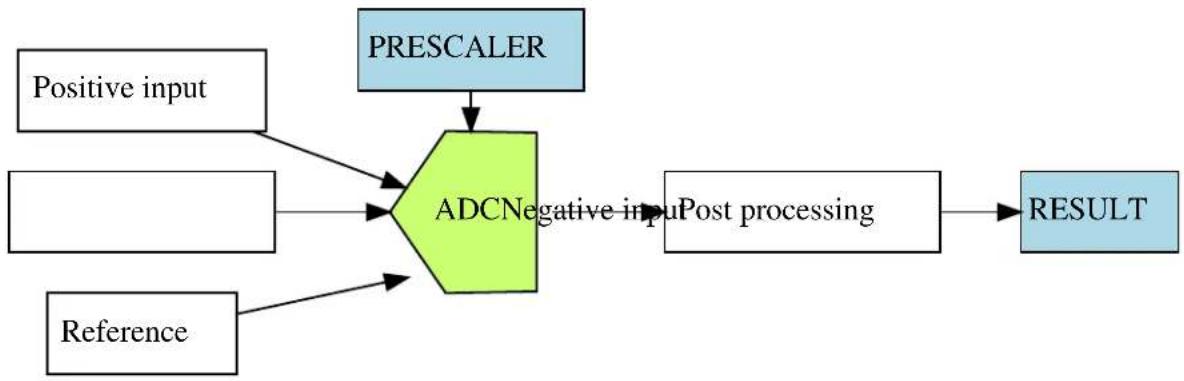
flowchart
graph TD
    A["Positive input"] --> C["ADCNegative input"]
    B["Reference"] --> C
    C --> D["Post processing"]
    E["PREScaler"] --> C
    D --> F["RESULT"]
2.2.1 Sample Clock Prescaler
The ADC features a prescaler which enables conversion at lower clock rates than the input Generic Clock to the ADC module. This feature can be used to lower the synchronization time of the digital interface to the ADC module via a high speed Generic Clock frequency, while still allowing the ADC sampling rate to be reduced.
2.2.2 ADC Resolution
The ADC supports full 8-bit, 10-bit or 12-bit resolution. Hardware oversampling and decimation can be used to increase the effective resolution at the expense of throughput. Using oversampling and decimation mode the ADC resolution is increased from 12-bits to an effective 13, 14, 15 or 16-bits. In these modes the conversion rate is reduced, as a greater number of samples is used to achieve the increased resolution. The available resolutions and effective conversion rate is listed in Table 2-1: Effective ADC conversion speed using oversampling on page 44.
Table 2-1. Effective ADC conversion speed using oversampling
| Resolution Effective conversion rate | |
| 13-bits Conversion rate divided by 4 | |
| 14-bits Conversion rate divided by 16 | |
| 15-bits Conversion rate divided by 64 | |
| 16-bits Conversion rate divided by 256 |
2.2.3 Conversion Modes
ADC conversions can be software triggered on demand by the user application, if continuous sampling is not required. It is also possible to configure the ADC in free-running mode, where new conversions are started as soon as the previous conversion is completed, or configure the ADC to scan across a number of input pins (see Pin Scan).
2.2.4 Differential and Single-Ended Conversion
The ADC has two conversion modes; differential and single-ended. When measuring signals where the positive input pin is always at a higher voltage than the negative input pin, the single-ended conversion mode should be used in order to achieve a full 12-bit output resolution.
If however the positive input pin voltage may drop below the negative input pin the signed differential mode should be used.
2.2.5 Sample Time
The sample time for each ADC conversion is configurable as a number of half prescaled ADC clock cycles (depending on the prescaler value), allowing the user application to achieve faster or slower sampling depending on the source impedance of the ADC input channels. For applications with high impedance inputs the sample time can be increased to give the ADC an adequate time to sample and convert the input channel.
The resulting sampling time is given by the following equation:
$$ t _ {S A M P L E} = (\text { sample length } + 1) \times \frac {A D C _ {C L K}}{2} \tag {2.1} $$
2.2.6 Averaging
The ADC can be configured to trade conversion speed for accuracy by averaging multiple samples in hardware. This feature is suitable when operating in noisy conditions.
You can specify any number of samples to accumulate (up to 1024) and the divide ratio to use (up to divide by 128). To modify these settings the ADC_RESOLUTION_CUSTOM needs to be set as the resolution. When this is set the number of samples to accumulate and the division ratio can be set by the configuration struct members adc_config::accumulate_samples and adc_config::divide_result When using this mode the ADC result register will be set to be 16-bits wide to accommodate the larger result sizes produced by the accumulator.
The effective ADC conversion rate will be reduced by a factor of the number of accumulated samples; however the effective resolution will be increased according to Table 2-2: Effective ADC resolution from various hardware averaging modes on page 45.
Table 2-2. Effective ADC resolution from various hardware averaging modes
| Number of Samples Final Result | |
| 1 12-bits | |
| 2 13-bits | |
| 4 14-bits | |
| 8 15-bits | |
| 16 16-bits | |
| 32 16-bits | |
| 64 16-bits | |
| 128 16-bits | |
| 256 16-bits | |
| 512 16-bits | |
| 1024 16-bits |
2.2.7 Offset and Gain Correction
Inherent gain and offset errors affect the absolute accuracy of the ADC.
The offset error is defined as the deviation of the ADC's actual transfer function from ideal straight line at zero input voltage.
The gain error is defined as the deviation of the last output step's midpoint from the ideal straight line, after compensating for offset error.
The offset correction value is subtracted from the converted data before the result is ready. The gain correction value is multiplied with the offset corrected value.
The equation for both offset and gain error compensation is shown below:
$$ A D C _ {R E S U L T} = (V A L U E _ {C O N V} + C O R R _ {O F F S E T}) \times C O R R _ {G A I N} \tag {2.2} $$
When enabled, a given set of offset and gain correction values can be applied to the sampled data in hardware, giving a corrected stream of sample data to the user application at the cost of an increased sample latency.
In single conversion, a latency of 13 ADC Generic Clock cycles is added for the final sample result availability. As the correction time is always less than the propagation delay, in free running mode this latency appears only during the first conversion. After the first conversion is complete future conversion results are available at the defined sampling rate.
2.2.8 Pin Scan
In pin scan mode, the first ADC conversion will begin from the configured positive channel, plus the requested starting offset. When the first conversion is completed, the next conversion will start at the next positive input channel and so on, until all requested pins to scan have been sampled and converted.
Pin scanning gives a simple mechanism to sample a large number of physical input channel samples, using a single physical ADC channel.
2.2.9 Window Monitor
The ADC module window monitor function can be used to automatically compare the conversion result against a preconfigured pair of upper and lower threshold values.
The threshold values are evaluated differently, depending on whether differential or single-ended mode is selected. In differential mode, the upper and lower thresholds are evaluated as signed values for the comparison, while in single-ended mode the comparisons are made as a set of unsigned values.
The significant bits of the lower window monitor threshold and upper window monitor threshold values are user-configurable, and follow the overall ADC sampling bit precision set when the ADC is configured by the user application. For example, only the eight lower bits of the window threshold values will be compared to the sampled data whilst the ADC is configured in 8-bit mode. In addition, if using differential mode, the 8th bit will be considered as the sign bit even if bit 9 is zero.
2.2.10 Events
Event generation and event actions are configurable in the ADC.
The ADC has two actions that can be triggered upon event reception:
- Start conversion
- Flush pipeline and start conversion
The ADC can generate two events:
- Window monitor
- Result ready
If the event actions are enabled in the configuration, any incoming event will trigger the action.
If the window monitor event is enabled, an event will be generated when the configured window condition is detected.
If the result ready event is enabled, an event will be generated when a conversion is completed.
Note
The connection of events between modules requires the use of the SAM D20/D21 Event System Driver (EVENTS) to route output event of one module to the input event of another. For more information on event routing, refer to the event driver documentation.
2.3 Special Considerations
An integrated analog temperature sensor is available for use with the ADC. The bandgap voltage, as well as the scaled IO and core voltages can also be measured by the ADC. For internal ADC inputs, the internal source(s) may need to be manually enabled by the user application before they can be measured.
2.4 Extra Information
For extra information see Extra Information for ADC Driver. This includes:
- Acronyms
-
Dependencies
-
Errata
- Module History
2.5 Examples
For a list of examples related to this driver, see Examples for ADC Driver.
2.6 API Overview
2.6.1 Variable and Type Definitions
2.6.1.1 Type adc_callback_t
typedef void(* adc_callback_t )(const struct adc_module *const module)
Type of the callback functions
2.6.2 Structure Definitions
2.6.2.1 Struct adc_config
Configuration structure for an ADC instance. This structure should be initialized by the adc_get_config_defaults() function before being modified by the user application.
Table 2-3. Members
| Type Name Description | ||
| enum adc_accumulate_samples accumulate_samples Number of ADC samples to accumulate when using the ADC_RESOLUTION_CUSTOM mode | ||
| enum adc_clock_prescaler clock_prescaler Clock prescaler | ||
| enum gclk_generator clock_source GCLK generator used to clock the peripheral | ||
| struct adc_correction_config correction Gain and offset correction configuration structure | ||
| bool differential_mode Enables differential mode if true | ||
| enum adc_divide_result | divide_result | Division ration when using the ADC_RESOLUTION_CUSTOM mode |
| enum adc_event_action | event_action | Event action to take on incoming event |
| bool freerunning | Enables free running mode if true | |
| enum adc_gain_factor | gain_factor | Gain factor |
| bool left_adjust | Left adjusted result | |
| enum adc_negative_input | negative_input | Negative MUX input |
| struct adc_pin_scan_config | pin_scan | Pin scan configuration structure |
| enum adc_positive_input | positive_input | Positive MUX input |
| enum adc_reference | reference | Voltage reference |
| bool | reference_compensation_enable | Enables reference buffer offset compensation if true. This willincrease the accuracy of the gain stage, but decreases the input impedance; therefore the startup time of the reference must be increased. |
| enum adc_resolution resolution Result resolution | ||
| bool run_in_standby Enables ADC in standby sleep | mode if true | |
| uint8_t sample_length This value (0-63) control the | ADC sampling time in number of half ADC prescaled clock cycles (depends of ADC_PRESCALER value), thus controlling the ADC input impedance. Sampling time is set according to the formula: Sample time = (sample_length+1) * (ADCclk / 2) | |
| struct adc_window_config window Window monitor configuration | structure | |
2.6.2.2 Struct adc\_correction\_config
Gain and offset correction configuration structure. Part of the adc_config struct and will be initialized by adc_get_config_defaults.
Table 2-4. Members
| Type Name Description | ||
| bool correction_enable Enables correction for gain | and offset based on values of gain_correction and offset_correction if set to true. | |
| uint16_t gain_correction This value defines how the ADC | conversion result is compensated for gain error before written to the result register. This is a fractional value, 1-bit integer plus an 11-bit fraction, therefore 1/2 <= gain_correction < 2. Valid gain_correction values ranges from 0b010000000000 to 0b111111111111. | |
| int16_t offset_correction This value defines how the ADC | conversion result is compensated for offset error before written to the result register. This is a 12-bit value in two's complement format. | |
2.6.2.3 Struct adc\_events
Event flags for the ADC module. This is used to enable and disable events via adc_enable_events() and adc_disable_events().
Table 2-5. Members
| Type Name Description | ||
| bool generate_event_on_conversion_done Enable event generation on | conversion done | |
| bool generate_event_on_window_monitor Enable event generation on | window monitor | |
2.6.2.4 Struct adc\_module
ADC software instance structure, used to retain software state information of an associated hardware module instance.
Note
The fields of this structure should not be altered by the user application; they are reserved for module-internal use only.
2.6.2.5 Struct adc\_pin\_scan\_config
Pin scan configuration structure. Part of the adc_config struct and will be initialized by adc_get_config_defaults.
Table 2-6. Members
| Type Name Description | ||
| uint8_t inputs_to_scan Number of input pins to scan in pin | scan mode. A value below 2 will disable pin scan mode. | |
| uint8_t offset_start_scan Offset (relative to selected positive | input) of the first input pin to be used in pin scan mode. | |
2.6.2.6 Struct adc\_window\_config
Window monitor configuration structure.
Table 2-7. Members
| Type Name Description | ||
| int32_t window_lower_value Lower window value | ||
| enum adc_window_mode window_mode Selected window mode | ||
| int32_t window_upper_value Upper window value |
2.6.3 Macro Definitions
2.6.3.1 Module status flags
ADC status flags, returned by adc_get_status() and cleared by adc_clear_status().
Macro ADC_STATUS_RESULT_READY
#define ADC_STATUS_RESULT_READY (1UL << 0)
ADC result ready
Macro ADC_STATUS_WINDOW
#define ADC_STATUS_WINDOW (1UL << 1)
Window monitor match
Macro ADC_STATUS_OVERRUN
#define ADC_STATUS_OVERRUN (1UL << 2)
ADC result overwritten before read
2.6.4 Function Definitions
2.6.4.1 Driver initialization and configuration
Function adc_init()
Initializes the ADC.
enum status_code adc_init(
    struct adc_module *const module_inst,
    Adc * hw,
    struct adc_config * config)
Initializes the ADC device struct and the hardware module based on the given configuration struct values.
Table 2-8. Parameters
| Data direction Parameter name Description | |
| [out] module_inst Pointer to the ADC software | instance struct |
| [in] hw Pointer to the ADC module | instance |
| [in] config Pointer to the configuration struct |
Returns
Status of the initialization procedure
Table 2-9. Return Values
| Return value Description | |
| STATUS_OK The initialization was successful | |
| STATUS_ERR_INVALID_ARG Invalid argument(s) were provided | |
| STATUS_BUSY The module is busy with a reset operation | |
| STATUS_ERR_DENIED The module is enabled | |
Function adc\_get\_config\_defaults()
Initializes an ADC configuration structure to defaults.
void adc_get_config_defaults(
    struct adc_config *const config)
Initializes a given ADC configuration struct to a set of known default values. This function should be called on any new instance of the configuration struct before being modified by the user application.
The default configuration is as follows:
• GCLK generator 0 (GCLK main) clock source
• 1V from internal bandgap reference
• Div 4 clock prescaler
- 12 bit resolution
• Window monitor disabled
- No gain
• Positive input on ADC PIN 0
- Negative input on ADC PIN 1
- Averaging disabled
• Oversampling disabled
- Right adjust data
- Single-ended mode
• Free running disabled
• All events (input and generation) disabled
- Sleep operation disabled
• No reference compensation
- No gain/offset correction
- No added sampling time
• Pin scan mode disabled
Table 2-10. Parameters
| Data direction Parameter name Description | |
| [out] config Pointer to configuration struct to | initialize to default values |
2.6.4.2 Status Management
Function adc_get_status()
Retrieves the current module status.
uint32_t adc_get_status(
    struct adc_module *const module_inst)
Retrieves the status of the module, giving overall state information.
Table 2-11. Parameters
| Data direction Parameter name Description | |
| [in] module_inst Pointer to the ADC software | instance struct |
Returns
Bitmask of ADC_STATUS_* flags
Table 2-12. Return Values
| Return value Description | |
| ADC_STATUS_RESULT_READY ADC Result is ready to be read | |
| ADC_STATUS_WINDOW ADC has detected a value inside the set window range | |
| ADC_STATUS_OVERRUN ADC result has overrun | |
Function adc\_clear\_status()
Clears a module status flag.
void adc_clear_status(
    struct adc_module *const module_inst,
    const uint32_t status_flags)
Clears the given status flag of the module.
Table 2-13. Parameters
| Data direction Parameter name Description | |
| [in] module_inst Pointer to the ADC software | instance struct |
| [in] status_flags | Bitmask of ADC_STATUS_* flags to clear |
2.6.4.3 Enable, disable and reset ADC module, start conversion and read result
Function adc\_is\_syncing()
Determines if the hardware module(s) are currently synchronizing to the bus.
bool adc_is_syncing(
    struct adc_module *const module_inst)
Checks to see if the underlying hardware peripheral module(s) are currently synchronizing across multiple clock domains to the hardware bus. This function can be used to delay further operations on a module until such time that it is ready, to prevent blocking delays for synchronization in the user application.
Table 2-14. Parameters
| Data direction Parameter name Description | |
| [in] module_inst Pointer to the ADC software | instance struct |
Returns
Synchronization status of the underlying hardware module(s).
Table 2-15. Return Values
| Return value Description | |
| true if the module has completed synchronization | |
| false if the module synchronization is ongoing |
Function adc\_enable()
Enables the ADC module.
enum status_code adc_enable(
    struct adc_module *const module_inst)
Enables an ADC module that has previously been configured. If any internal reference is selected it will be enabled.
Table 2-16. Parameters
| Data direction Parameter name Description | |
| [in] module_inst Pointer to the ADC software | instance struct |
Function adc\_disable()
Disables the ADC module.
enum status_code adc_disable(
    struct adc_module *const module_inst)
Disables an ADC module that was previously enabled.
Table 2-17. Parameters
| Data direction Parameter name Description | |
| [in] module_inst Pointer to the ADC software | instance struct |
Function adc\_reset()
Resets the ADC module.
enum status_code adc_reset(
    struct adc_module *const module_inst)
Resets an ADC module, clearing all module state and registers to their default values.
Table 2-18. Parameters
| Data direction Parameter name Description | |
| [in] module_inst Pointer to the ADC software | instance struct |
Function adc\_enable\_events()
Enables an ADC event input or output.
void adc_enable_events(
    struct adc_module *const module_inst,
    struct adc_events *const events)
Enables one or more input or output events to or from the ADC module. See here for a list of events this module supports.
Note
Events cannot be altered while the module is enabled.
Table 2-19. Parameters
| Data direction Parameter name Description | |
| [in] module_inst Software instance for the ADC | peripheral |
| [in] events Struct containing flags of events to | enable |
Function adc\_disable\_events()
Disables an ADC event input or output.
void adc_disable_events(
    struct adc_module *const module_inst,
    struct adc_events *const events)
Disables one or more input or output events to or from the ADC module. See here for a list of events this module supports.
Note
Events cannot be altered while the module is enabled.
Table 2-20. Parameters
| Data direction Parameter name Description | |
| [in] module_inst Software instance for the ADC | peripheral |
| [in] events Struct containing flags of events to | disable |
Function adc\_start\_conversion()
Starts an ADC conversion.
void adc_start_conversion(
    struct adc_module *const module_inst)
Starts a new ADC conversion.
Table 2-21. Parameters
| Data direction Parameter name Description | |
| [in] module_inst Pointer to the ADC software | instance struct |
Function adc\_read()
Reads the ADC result.
enum status_code adc_read(
    struct adc_module *const module_inst,
    uint16_t * result)
Reads the result from an ADC conversion that was previously started.
Table 2-22. Parameters
| Data direction Parameter name Description | |
| [in] module_inst Pointer to the ADC software | instance struct |
| [out] result Pointer to store the result value in |
Returns
Status of the ADC read request.
Table 2-23. Return Values
| Return value Description | |
| STATUS_OK The result was retrieved successfully | |
| STATUS_BUSY A conversion result was not ready | |
| STATUS_ERR_OVERFLOW The result register has been overwritten by the ADC module before the result was read by the software | |
2.6.4.4 Runtime changes of ADC module
Function adc\_flush()
Flushes the ADC pipeline.
void adc_flush(
    struct adc_module *const module_inst)
Flushes the pipeline and restart the ADC clock on the next peripheral clock edge. All conversions in progress will be lost. When flush is complete, the module will resume where it left off.
Table 2-24. Parameters
| Data direction Parameter name Description | |
| [in] module_inst Pointer to the ADC software | instance struct |
Function adc\_set\_window\_mode()
Sets the ADC window mode.
void adc_set_window_mode(
    struct adc_module *const module_inst,
    const enum adc_window_mode window_mode,
    const int16_t window_lower_value,
    const int16_t window_upper_value)
Sets the ADC window mode to a given mode and value range.
Table 2-25. Parameters
| Data direction Parameter name Description | |
| [in] module_inst Pointer to the ADC software | instance struct |
| [in] window_mode Window monitor mode to set | |
| [in] window_lower_value Lower window monitor threshold | value |
| [in] window_upper_value Upper window monitor threshold | value |
Function adc\_set\_gain()
Sets ADC gain factor.
void adc_set_gain(
    struct adc_module *const module_inst,
    const enum adc_gain_factor gain_factor)
Sets the ADC gain factor to a specified gain setting.
Table 2-26. Parameters
| Data direction Parameter name Description | |
| [in] module_inst Pointer to the ADC software | instance struct |
| [in] gain_factor Gain factor value to set |
Function adc\_set\_pin\_scan\_mode()
Sets the ADC pin scan mode.
enum status_code adc_set_pin_scan_mode(
    struct adc_module *const module_inst,
    uint8_t inputs_to_scan,
    const uint8_t start_offset)
Configures the pin scan mode of the ADC module. In pin scan mode, the first conversion will start at the configured positive input + start_offset. When a conversion is done, a conversion will start on the next input, until inputs_to_scan number of conversions are made.
Table 2-27. Parameters
| Data direction Parameter name Description | |
| [in] module_inst Pointer to the ADC software | instance struct |
| [in] inputs_to_scan Number of input pins to perform | a conversion on (must be two or more) |
| [in] start_offset Offset of first pin to scan (relative | to configured positive input) |
Returns
Status of the pin scan configuration set request.
Table 2-28. Return Values
| Return value Description | |
| STATUS_OK Pin scan mode has been set successfully | |
| STATUS_ERR_INVALID_ARG Number of input pins to scan or offset has an invalid value |
Function adc\_disable\_pin\_scan\_mode()
Disables pin scan mode.
void adc_disable_pin_scan_mode(
    struct adc_module *const module_inst)
Disables pin scan mode. The next conversion will be made on only one pin (the configured positive input pin).
Table 2-29. Parameters
| Data direction Parameter name Description | |
| [in] module_inst Pointer to the ADC software | instance struct |
Function adc\_set\_positive\_input()
Sets positive ADC input pin.
void adc_set_positive_input(
    struct adc_module *const module_inst,
    const enum adc_positive_input positive_input)
Sets the positive ADC input pin selection.
Table 2-30. Parameters
| Data direction Parameter name Description | |
| [in] module_inst Pointer to the ADC software | instance struct |
| [in] positive_input Positive input pin |
Function adc\_set\_negative\_input()
Sets negative ADC input pin for differential mode.
void adc_set_negative_input(
    struct adc_module *const module_inst,
    const enum adc_negative_input negative_input)
Sets the negative ADC input pin, when the ADC is configured in differential mode.
Table 2-31. Parameters
| Data direction Parameter name Description | |
| [in] module_inst Pointer to the ADC software | instance struct |
| [in] negative_input Negative input pin |
2.6.4.5 Enable and disable interrupts
Function adc\_enable\_interrupt()
Enable interrupt.
void adc_enable_interrupt(
    struct adc_module *const module_inst,
    enum adc_interrupt_flag interrupt)
Enable the given interrupt request from the ADC module.
Table 2-32. Parameters
| Data direction Parameter name Description | |
| [in] module_inst Pointer to the ADC software | instance struct |
| [in] interrupt Interrupt to enable |
Function adc\_disable\_interrupt()
Disable interrupt.
void adc_disable_interrupt(
    struct adc_module *const module_inst,
    enum adc_interrupt_flag interrupt)
Disable the given interrupt request from the ADC module.
Table 2-33. Parameters
| Data direction Parameter name Description | |
| [in] module_inst Pointer to the ADC software | instance struct |
| [in] interrupt Interrupt to disable |
2.6.4.6 Callback Management
Function adc\_register\_callback()
Registers a callback.
void adc_register_callback(
    struct adc_module *const module,
    adc_callback_t callback_func,
    enum adc_callback callback_type)
Registers a callback function which is implemented by the user.
Note
The callback must be enabled by for the interrupt handler to call it when the condition for the callback is met.
Table 2-34. Parameters
| Data direction Parameter name Description | |
| [in] module Pointer to ADC software instance | struct |
| [in] callback_func Pointer to callback function | |
| [in] callback_type Callback type given by an enum |
Function adc\_unregister\_callback()
Unregisters a callback.
void adc_unregister_callback(
    struct adc_module * module,
    enum adc_callback callback_type)
Unregisters a callback function which is implemented by the user.
Table 2-35. Parameters
| Data direction Parameter name Description | |
| [in] module Pointer to ADC software instance | struct |
| [in] callback_type Callback type given by an enum |
Function adc\_enable\_callback()
Enables callback.
void adc_enable_callback(
    struct adc_module *const module,
    enum adc_callback callback_type)
Enables the callback function registered by adc_register_callback. The callback function will be called from the interrupt handler when the conditions for the callback type are met.
Table 2-36. Parameters
| Data direction Parameter name Description | |
| [in] module Pointer to ADC software instance | struct |
| [in] callback_type Callback type given by an enum |
Returns
Status of the operation
Table 2-37. Return Values
| Return value Description | |
| STATUS_OK If operation was completed | |
| STATUS_ERR_INVALID If operation was not completed, due to invalid callback_type | |
Function adc\_disable\_callback()
Disables callback.
void adc_disable_callback(
    struct adc_module *const module,
    enum adc_callback callback_type)
Disables the callback function registered by the adc_register_callback.
Table 2-38. Parameters
| Data direction Parameter name Description | |
| [in] module Pointer to ADC software instance | struct |
| [in] callback_type Callback type given by an enum |
Returns
Status of the operation
Table 2-39. Return Values
| Return value Description | |
| STATUS_OK If operation was completed | |
| STATUS_ERR_INVALID If operation was not completed, due to invalid callback_type | |
2.6.4.7 Job Management
Function adc\_read\_buffer\_job()
Read multiple samples from ADC.
enum status_code adc_read_buffer_job(
    struct adc_module *const module_inst,
    uint16_t * buffer,
uint16_t samples)
Read samples samples from the ADC into the buffer buffer. If there is no hardware trigger defined (event action) the driver will retrigger the ADC conversion whenever a conversion is complete until samples samples has been acquired. To avoid jitter in the sampling frequency using an event trigger is advised.
Table 2-40. Parameters
| Data direction Parameter name Description | |
| [in] module_inst Pointer to the ADC software | instance struct |
| [in] samples Number of samples to acquire | |
| [out] buffer Buffer to store the ADC samples |
Returns
Status of the job start
Table 2-41. Return Values
| Return value Description | |
| STATUS_OK The conversion job was started successfully and is in progress | |
| STATUS_BUSY The ADC is already busy with another job | |
Function adc\_get\_job\_status()
Gets the status of a job.
enum status_code adc_get_job_status(
    struct adc_module * module_inst,
    enum adc_job_type type)
Gets the status of an ongoing or the last job.
Table 2-42. Parameters
| Data direction Parameter name Description | |
| [in] module_inst Pointer to the ADC software | instance struct |
| [in] type Type of job to abort |
Returns
Status of the job
Function adc\_abort\_job()
Aborts an ongoing job.
void adc_abort_job(
    struct adc_module * module_inst,
    enum adc_job_type type)
Aborts an ongoing job.
Table 2-43. Parameters
| Data direction Parameter name Description | |
| [in] module_inst Pointer to the ADC software | instance struct |
| [in] type Type of job to abort |
2.6.5 Enumeration Definitions
2.6.5.1 Enum adc\_accumulate\_samples
Enum for the possible numbers of ADC samples to accumulate. This setting is only used when the ADC_RESOLUTION_CUSTOM on page 66 resolution setting is used.
Table 2-44. Members
| Enum value Description | |
| ADC_ACCUMULATE_DISABLE No averaging | |
| ADC_ACCUMULATE_SAMPLES_2 Average 2 samples | |
| ADC_ACCUMULATE_SAMPLES_4 Average 4 samples | |
| ADC_ACCUMULATE_SAMPLES_8 Average 8 samples | |
| ADC_ACCUMULATE_SAMPLES_16 Average 16 samples | |
| ADC_ACCUMULATE_SAMPLES_32 Average 32 samples | |
| ADC_ACCUMULATE_SAMPLES_64 Average 64 samples | |
| ADC_ACCUMULATE_SAMPLES_128 Average 128 samples | |
| ADC_ACCUMULATE_SAMPLES_256 Average 265 samples | |
| ADC_ACCUMULATE_SAMPLES_512 Average 512 samples | |
| ADC_ACCUMULATE_SAMPLES_1024 Average 1024 samples |
2.6.5.2 Enum adc\_callback
Callback types for ADC callback driver
Table 2-45. Members
| Enum value Description | |
| ADC_CALLBACK_READ_BUFFER Callback for buffer received | |
| ADC_CALLBACK_WINDOW Callback when window is hit | |
| ADC_CALLBACK_ERROR | Callback for error |
2.6.5.3 Enum adc\_clock\_prescaler
Enum for the possible clock prescaler values for the ADC.
Table 2-46. Members
| Enum value Description | |
| ADC_CLOCK_PRESCALER_DIV4 | ADC clock division factor 4 |
| ADC_CLOCK_PRESCALER_DIV8 ADC clock division factor 8 | |
| ADC_CLOCK_PRESCALER_DIV16 ADC clock division factor 16 | |
| ADC_CLOCK_PRESCALER_DIV32 ADC clock division factor 32 | |
| ADC_CLOCK_PRESCALER_DIV64 ADC clock division factor 64 | |
| ADC_CLOCK_PRESCALER_DIV128 ADC clock division factor 128 | |
| ADC_CLOCK_PRESCALER_DIV256 ADC clock division factor 256 | |
| ADC_CLOCK_PRESCALER_DIV512 ADC clock division factor 512 |
2.6.5.4 Enum adc\_divide\_result
Enum for the possible division factors to use when accumulating multiple samples. To keep the same resolution for the averaged result and the actual input value the division factor must be equal to the number of samples accumulated. This setting is only used when the ADC_RESOLUTION_CUSTOM on page 66 resolution setting is used.
Table 2-47. Members
| Enum value Description | |
| ADC_DIVIDE_RESULT_DISABLE Don't divide result register after accumulation | |
| ADC_DIVIDE_RESULT_2 Divide result register by 2 after accumulation | |
| ADC_DIVIDE_RESULT_4 Divide result register by 4 after accumulation | |
| ADC_DIVIDE_RESULT_8 Divide result register by 8 after accumulation | |
| ADC_DIVIDE_RESULT_16 Divide result register by 16 after accumulation | |
| ADC_DIVIDE_RESULT_32 Divide result register by 32 after accumulation | |
| ADC_DIVIDE_RESULT_64 Divide result register by 64 after accumulation | |
| ADC_DIVIDE_RESULT_128 Divide result register by 128 after accumulation | |
2.6.5.5 Enum adc\_event\_action
Enum for the possible actions to take on an incoming event.
Table 2-48. Members
| Enum value Description | |
| ADC_EVENT_ACTION_DISABLED Event action disabled | |
| ADC_EVENT_ACTION_FLUSH_START_CONV Flush ADC and start conversion | |
| ADC_EVENT_ACTION_START_CONV Start conversion | |
2.6.5.6 Enum adc\_gain\_factor
Enum for the possible gain factor values for the ADC.
Table 2-49. Members
| Enum value Description | |
| ADC_GAIN_FACTOR_1X 1x gain | |
| ADC_GAIN_FACTOR_2X 2x gain | |
| ADC_GAIN_FACTOR_4X 4x gain | |
| ADC_GAIN_FACTOR_8X 8x gain | |
| ADC_GAIN_FACTOR_16X 16x gain | |
| ADC_GAIN_FACTOR_DIV2 1/2x gain |
2.6.5.7 Enum adc\_interrupt\_flag
Enum for the possible ADC interrupt flags
Table 2-50. Members
| Enum value Description | |
| ADC_INTERRUPT_RESULT_READY ADC result ready | |
| ADC_INTERRUPT_WINDOW Window monitor match | |
| ADC_INTERRUPT_OVERRUN ADC result overwritten before read |
2.6.5.8 Enum adc\_job\_type
Enum for the possible types of ADC asynchronous jobs that may be issued to the driver.
Table 2-51. Members
| Enum value Description | |
| ADC_JOB_READ_BUFFER Asynchronous ADC read into a user provided buffer | |
2.6.5.9 Enum adc\_negative\_input
Enum for the possible negative MUX input selections for the ADC.
Table 2-52. Members
| Enum value Description | |
| ADC_NEGATIVE_INPUT_PIN0 ADC0 pin | |
| ADC_NEGATIVE_INPUT_PIN1 ADC1 pin | |
| ADC_NEGATIVE_INPUT_PIN2 ADC2 pin | |
| ADC_NEGATIVE_INPUT_PIN3 ADC3 pin | |
| ADC_NEGATIVE_INPUT_PIN4 ADC4 pin | |
| ADC_NEGATIVE_INPUT_PIN5 ADC5 pin | |
| ADC_NEGATIVE_INPUT_PIN6 ADC6 pin | |
| ADC_NEGATIVE_INPUT_PIN7 ADC7 pin | |
| ADC_NEGATIVE_INPUT_GND Internal ground | |
| ADC_NEGATIVE_INPUT_IOGND I/O ground |
2.6.5.10 Enum adc\_oversampling\_and\_decimation
Enum for the possible numbers of bits resolution can be increased by when using oversampling and decimation.
Table 2-53. Members
| Enum value Description | |
| ADC_OVERSAMPLING_AND_DECIMATION_DISABLE Don't use oversampling and decimation mode | |
| ADC_OVERSAMPLING_AND_DECIMATION_1BIT 1 bit resolution increase | |
| ADC_OVERSAMPLING_AND_DECIMATION_2BIT 2 bits resolution increase | |
| ADC_OVERSAMPLING_AND_DECIMATION_3BIT 3 bits resolution increase | |
| ADC_OVERSAMPLING_AND_DECIMATION_4BIT 4 bits resolution increase | |
2.6.5.11 Enum adc\_positive\_input
Enum for the possible positive MUX input selections for the ADC.
Table 2-54. Members
| Enum value Description | |
| ADC_POSITIVE_INPUT_PIN0 ADC0 pin | |
| ADC_POSITIVE_INPUT_PIN1 ADC1 pin | |
| ADC_POSITIVE_INPUT_PIN2 ADC2 pin | |
| ADC_POSITIVE_INPUT_PIN3 ADC3 pin | |
| ADC_POSITIVE_INPUT_PIN4 ADC4 pin | |
| ADC_POSITIVE_INPUT_PIN5 ADC5 pin | |
| ADC_POSITIVE_INPUT_PIN6 ADC6 pin | |
| ADC_POSITIVE_INPUT_PIN7 ADC7 pin | |
| ADC_POSITIVE_INPUT_PIN8 ADC8 pin | |
| ADC_POSITIVE_INPUT_PIN9 ADC9 pin | |
| ADC_POSITIVE_INPUT_PIN10 ADC10 pin | |
| ADC_POSITIVE_INPUT_PIN11 ADC11 pin | |
| ADC_POSITIVE_INPUT_PIN12 ADC12 pin | |
| ADC_POSITIVE_INPUT_PIN13 ADC13 pin | |
| ADC_POSITIVE_INPUT_PIN14 ADC14 pin | |
| ADC_POSITIVE_INPUT_PIN15 ADC15 pin | |
| ADC_POSITIVE_INPUT_PIN16 ADC16 pin | |
| ADC_POSITIVE_INPUT_PIN17 ADC17 pin | |
| ADC_POSITIVE_INPUT_PIN18 ADC18 pin | |
| ADC_POSITIVE_INPUT_PIN19 ADC19 pin | |
| ADC_POSITIVE_INPUT_TEMP Temperature reference | |
| ADC_POSITIVE_INPUT_BANDGAP Bandgap voltage | |
| ADC_POSITIVE_INPUT_SCALEDCOREVCC 1/4 scaled core supply | |
| ADC_POSITIVE_INPUT_SCALEDIOVCC 1/4 scaled I/O supply | |
| ADC_POSITIVE_INPUT_DAC DAC input |
2.6.5.12 Enum adc\_reference
Enum for the possible reference voltages for the ADC.
Table 2-55. Members
| Enum value Description | |
| ADC_REFERENCE_INT1V 1.0V voltage reference | |
| ADC_REFERENCE_INTVCC0 1/1.48 VCC reference | |
| ADC_REFERENCE_INTVCC1 1/2 VCC (only for internal Vcc > 2.1v) | |
| ADC_REFERENCE_AREFA External reference A | |
| ADC_REFERENCE_AREFB External reference B |
2.6.5.13 Enum adc\_resolution
Enum for the possible resolution values for the ADC.
Table 2-56. Members
| Enum value Description | |
| ADC_RESOLUTION_12BIT ADC 12-bit resolution | |
| ADC_RESOLUTION_16BIT ADC 16-bit resolution using oversampling and decimation | |
| ADC_RESOLUTION_10BIT ADC 10-bit resolution | |
| ADC_RESOLUTION_8BIT ADC 8-bit resolution | |
| ADC_RESOLUTION_13BIT ADC 13-bit resolution using oversampling and decimation | |
| ADC_RESOLUTION_14BIT ADC 14-bit resolution using oversampling and decimation | |
| ADC_RESOLUTION_15BIT ADC 15-bit resolution using oversampling and decimation | |
| ADC_RESOLUTION_CUSTOM ADC 16-bit result register for use with averaging. When using this mode the ADC result register will be set to 16-bit wide, and the number of samples to accumulate and the division factor is configured by the adc_config::accumulate_samples and adc_config::divide_result members in the configuration struct | |
2.6.5.14 Enum adc\_window\_mode
Enum for the possible window monitor modes for the ADC.
Table 2-57. Members
| Enum value Description | |
| ADC_WINDOW_MODE_DISABLE No window mode | |
| ADC_WINDOW_MODE_ABOVE_LOWER RESULT > WINLT | |
| ADC_WINDOW_MODE_BELOW_UPPER RESULT < WINUT | |
| ADC_WINDOW_MODE_BETWEEN WINLT < RESULT < WINUT | |
| ADC_WINDOW_MODE_BETWEEN_INVERTED !(WINLT < RESULT < WINUT) |
2.7 Extra Information for ADC Driver
2.7.1 Acronyms
Below is a table listing the acronyms used in this module, along with their intended meanings.
| Acronym Description | |
| ADC Analog-to-Digital Converter | |
| DAC Digital-to-Analog Converter | |
| LSB Least Significant Bit | |
| MSB Most Significant Bit | |
| DMA Direct Memory Access |
2.7.2 Dependencies
This driver has the following dependencies:
• System Pin Multiplexer Driver
2.7.3 Errata
There are no errata related to this driver.
2.7.4 Module History
An overview of the module history is presented in the table below, with details on the enhancements and fixes made to the module since its first release. The current version of this corresponds to the newest version in the table.
| Changelog |
| Added support for SAMD21 and new DMA quick start guide. |
| Added ADC calibration constant loading from the device signature row when the module is initialized. |
| Initial Release |
2.8 Examples for ADC Driver
This is a list of the available Quick Start guides (QSGs) and example applications for SAM D20/D21 Analog to Digital Converter Driver (ADC). QSGs are simple examples with step-by-step instructions to configure and use this driver in a selection of use cases. Note that QSGs can be compiled as a standalone application or be added to the user application.
- Quick Start Guide for ADC - Basic
- Quick Start Guide for ADC - Callback
- Quick Start Guide for Using DMA with ADC/DAC
2.8.1 Quick Start Guide for ADC - Basic
In this use case, the ADC will be configured with the following settings:
• Div 4 clock prescaler
• 12 bit resolution
• Window monitor disabled
- No gain
• 1V from internal bandgap reference
• Positive input on ADC PIN 0
• Negative input on ADC PIN 1
- Averaging disabled
- Oversampling disabled
- Right adjust data
- Single-ended mode
• Free running disabled
- All events (input and generation) disabled
- Sleep operation disabled
• No reference compensation
- No gain/offset correction
• No added sampling time
• Pin scan mode disabled
2.8.1.1 Setup
Prerequisites
There are no special setup requirements for this use-case.
Code
Add to the main application source file, outside of any functions:
struct adc_module adc_instance;
Copy-paste the following setup code to your user application:
void configure_adc(void)
{
    struct adc_config config_adc;
    adc_get_config_defaults(&config_adc);

    adc_init(&adc_instance, ADC, &config_adc);

    adc_enable(&adc_instance);
}
Add to user application initialization (typically the start of main()):
configure_adc();
Workflow
- Create a module software instance structure for the ADC module to store the ADC driver state while it is in use.
struct adc_module adc_instance;
Note
This should never go out of scope as long as the module is in use. In most cases, this should be global.
- Configure the ADC module.
a. Create a ADC module configuration struct, which can be filled out to adjust the configuration of a physical ADC peripheral.
struct adc_config config_adc;
b. Initialize the ADC configuration struct with the module's default values.
adc_get_config_defaults(&config_adc);
Note
This should always be performed before using the configuration struct to ensure that all values are initialized to known default settings.
c. Enable the ADC module so that conversions can be made.
adc_enable(&adc_instance);
2.8.1.2 Use Case
Code
Copy-paste the following code to your user application:
adc_start_conversion(&adc_instance);
uint16_t result;
do {
    /* Wait for conversion to be done and read out result */
} while (adc_read(&adc_instance, &result) == STATUS_BUSY);
while (1) {
    /* Infinite loop */
}
Workflow
- Start conversion.
adc_start_conversion(&adc_instance);
- Wait until conversion is done and read result.
uint16_t result;
do {
    /* Wait for conversion to be done and read out result */
} while (adc_read(&adc_instance, &result) == STATUS_BUSY);
- Enter an infinite loop once the conversion is complete.
while (1) {
    /* Infinite loop */
}
2.8.2 Quick Start Guide for ADC - Callback
In this use case, the ADC will be convert 128 samples using interrupt driven conversion. When all samples have been sampled, a callback will be called that signals the main application that conversion is compete.
The ADC will be set up as follows:
• VCC / 2 as reference
• Div 8 clock prescaler
- 12 bit resolution
• Window monitor disabled
1/2 gain
• Positive input on ADC PIN 0
• Negative input to GND (Single ended)
- Averaging disabled
• Oversampling disabled
- Right adjust data
- Single-ended mode
• Free running disabled
• All events (input and generation) disabled
- Sleep operation disabled
• No reference compensation
- No gain/offset correction
• No added sampling time
• Pin scan mode disabled
2.8.2.1 Setup
Prerequisites
There are no special setup requirements for this use-case.
Code
Add to the main application source file, outside of any functions:
struct adc_module adc_instance;
#define ADC_SAMPLES 128
uint16_t adc_result_buffer[ADC_SAMPLES];
Callback function:
volatile bool adc_read_done = false;
void adc_complete_callback(
    const struct adc_module *const module)
{
    adc_read_done = true;
}
Copy-paste the following setup code to your user application:
void configure_adc(void)
{
    struct adc_config config_adc;
    adc_get_config_defaults(&config_adc);

    config_adc_gain_factor = ADC_GAIN_FACTOR_DIV2;
    config_adc.clock_prescaler = ADC_CLOCK_PRESCALER_DIV8;
    config_adc.reference = ADC_REFERENCE_INTVCC1;
    config_adc.positive_input = ADC_POSITIVE_INPUT_PIN4;
    config_adc.resolution = ADC_RESOLUTION_12BIT;

    adc_init(&adc_instance, ADC, &config_adc);

    adc_enable(&adc_instance);
}

void configure_adc_callbacks(void)
{
    adc_register_callback(&adc_instance,
    adc_complete_callback, ADC_CALLBACK_READ_BUFFER);
    adc_enable_callback(&adc_instance, ADC_CALLBACK_READ_BUFFER);
}
Add to user application initialization (typically the start of main()):
configure_adc();
configure_adc_callbacks();
Workflow
- Create a module software instance structure for the ADC module to store the ADC driver state while it is in use.
struct adc_module adc_instance;
Note
This should never go out of scope as long as the module is in use. In most cases, this should be global.
- Create a buffer for the ADC samples to be stored in by the driver asynchronously.
#define ADC_SAMPLES 128
uint16_t adc_result_buffer[ADC_SAMPLES];
- Create a callback function that will be called each time the ADC completes an asynchronous read job.
volatile bool adc_read_done = false;
void adc_complete_callback(
    const struct adc_module *const module)
{
    adc_read_done = true;
}
- Configure the ADC module.
a. Create a ADC module configuration struct, which can be filled out to adjust the configuration of a physical ADC peripheral.
struct adc_config config_adc;
b. Initialize the ADC configuration struct with the module's default values.
adc_get_config_defaults(&config_adc);
Note
This should always be performed before using the configuration struct to ensure that all values are initialized to known default settings.
c. Change the ADC module configuration to suit the application.
config_adc.gain_factor = ADC_GAIN_FACTOR_DIV2;
config_adc.clock_prescaler = ADC_CLOCK_PRESCALER_DIV8;
config_adc.reference = ADC_REFERENCE_INTVCC1;
config_adc.positive_input = ADC_POSITIVE_INPUT_PIN4;
config_adc.resolution = ADC_RESOLUTION_12BIT;
d. Enable the ADC module so that conversions can be made.
adc_enable(&adc_instance);
- Register and enable the ADC Read Buffer Complete callback handler
a. Register the user-provided Read Buffer Complete callback function with the driver, so that it will be run when an asynchronous buffer read job completes.
adc_register_callback(&adc_instance, adc_complete_callback, ADC_CALLBACK_READ_BUFFER);
b. Enable the Read Buffer Complete callback so that it will generate callbacks.
adc_enable_callback(&adc_instance, ADC_CALLBACK_READ_BUFFER);
2.8.2.2 Use Case
Code
Copy-paste the following code to your user application:
system_interrupt_enable_global();
adc_read_buffer_job(&adc_instance, adc_result_buffer, ADC_SAMPLES);
while (adc_read_done == false) {
    /* Wait for asynchronous ADC read to complete */
}
while (1) {
    /* Infinite loop */
}
Workflow
- Enable global interrupts, so that callbacks can be generated by the driver.
system_interrupt_enable_global();
- Start an asynchronous ADC conversion, to store ADC samples into the global buffer and generate a callback when complete.
adc_read_buffer_job(&adc_instance, adc_result_buffer, ADC_SAMPLES);
- Wait until the asynchronous conversion is complete.
while (adc_read_done == false) {
    /* Wait for asynchronous ADC read to complete */
}
- Enter an infinite loop once the conversion is complete.
while (1) {
    /* Infinite loop */
}
2.8.3 Quick Start Guide for Using DMA with ADC/DAC
The supported device list:
• SAMD21
This quick start will convert an analog input signal from PA4 and output the converted value to DAC on PA2. The data between ADC and DAC with be transferred through DMA instead of a CPU intervene.
The ADC will be configured with the following settings:
1/2 VDDANA
• Div 16 clock prescaler
- 10 bit resolution
• Window monitor disabled
- No gain
• Positive input on ADC PIN 4
• Averaging disabled
• Oversampling disabled
- Right adjust data
- Single-ended mode
- Free running enable
- All events (input and generation) disabled
- Sleep operation disabled
• No reference compensation
- No gain/offset correction
• No added sampling time
• Pin scan mode disabled
The DAC will be configured with the following settings:
• Analog VCC as reference
- Internal output disabled
- Drive the DAC output to PA2
- Right adjust data
- The output buffer is disabled when the chip enters STANDBY sleep mode
The DMA will be configured with the following settings:
- Move data from peripheral to peripheral
• Using ADC result ready trigger
• Using DMA priority level 0 - Beat transfer will be triggered on each trigger
- Loopback descriptor for DAC conversion
2.8.3.1 Setup
Prerequisites
There are no special setup requirements for this use-case.
Code
Add to the main application source file, outside of any functions:
struct dac_module dac_instance;
struct adc_module adc_instance;
struct dma_resource example_resource;
COMPILER_ALIGNED(16)
DmacDescriptor example_descriptor;
Copy-paste the following setup code to your user application:
void configure_adc(void)
{
    struct adc_config config_adc;

    adc_get_config_defaults(&config_adc);

    config_adc_gain_factor = ADC_GAIN_FACTOR_DIV2;
    config_adc.clock_prescaler = ADC_CLOCK_PRESCALER_DIV16;
    config_adc.reference = ADC_REFERENCE_INTVCC1;
    config_adc.positive_input = ADC_POSITIVE_INPUT_PIN4;
    config_adc.resolution = ADC_RESOLUTION_10BIT;
    config_adc.freerunning = true;
    config_adc.left_adjust = false;

    adc_init(&adc_instance, ADC, &config_adc);

    adc_enable(&adc_instance);
}

void configure_dac(void)
{
    struct dac_config config_dac;

    dac_get_config_defaults(&config_dac);

    config_dac.reference = DAC_REFERENCE_AVCC;

    dac_init(&dac_instance, DAC, &config_dac);

    dac_enable(&dac_instance);
}

void configure_dac_channel(void)
{
    struct dac_chan_config config_dac_chan;

    dac_chan_get_config_defaults(&config_dac_chan);

    dac_chan_set_config(&dac_instance, DAC_CHANNEL_0, &config_dac_chan);

    dac_chan_enable(&dac_instance, DAC_CHANNEL_0);
}

void configure_dma_resource(struct dma_resource *resource)
{
    struct dma_resource_config config;

    dma_get_config_defaults(&config);

    config peripheral_trigger = ADC_DMAC_ID_RESRDY;
    config trigger_action = DMA_TRIGGER_ACTION_BEAT;
dma_allocate(resource, &config);
}
void setup_transfer_descriptor(DmacDescriptor *descriptor)
{
    struct dma_descriptor_config descriptor_config;
    dma_descriptor_get_config_defaults(&descriptor_config);

    descriptor_config.beat_size = DMA_BEAT_SIZE_HWORD;
    descriptor_config.dst_increment_enable = false;
    descriptor_config.src_increment_enable = false;
    descriptor_config.block_transfer_count = 1000;
    descriptor_config.source_address = (uint32_t)(&adc_instance.hw->RESULT.reg);
    descriptor_config.destination_address = (uint32_t)(&dac_instance.hw->DATA.reg);
    descriptor_config.next_descriptor_address = (uint32_t)descriptor;

    dma_descriptor_createubescriptor, &descriptor_config);
}
Add to user application initialization (typically the start of main()):
configure_adc();
configure_dac();
configure_dac_channel();
configure_dma_resource(&example_resource);
setup_transfer_descriptor(&example_descriptor);
dma_add_descriptor(&example_resource, &example_descriptor);
Workflow
Configure the ADC
- Create a module software instance structure for the ADC module to store the ADC driver state while it is in use.
struct adc_module adc_instance;
Note
This should never go out of scope as long as the module is in use. In most cases, this should be global.
- Configure the ADC module.
a. Create a ADC module configuration struct, which can be filled out to adjust the configuration of a physical ADC peripheral.
struct adc_config config_adc;
b. Initialize the ADC configuration struct with the module's default values.
adc_get_config_defaults(&config_adc);
Note
This should always be performed before using the configuration struct to ensure that all values are initialized to known default settings.
c. Set extra configurations
config_adc.gain_factor = ADC_GAIN_FACTOR_DIV2;
config_adc.clock_prescaler = ADC_CLOCK_PRESCALER_DIV16;
config_adc.reference = ADC_REFERENCE_INTVCC1;
config_adc.positive_input = ADC_POSITIVE_INPUT_PIN4;
config_adc.resolution = ADC_RESOLUTION_10BIT;
config_adc.freerunning = true;
config_adc.left_adjust = false;
d. Set ADC configurations
adc_init(&adc_instance, ADC, &config_adc);
e. Enable the ADC module so that conversions can be made.
adc_enable(&adc_instance);
Configure the DAC
- Create a module software instance structure for the DAC module to store the DAC driver state while it is in use.
struct dac_module dac_instance;
Note
This should never go out of scope as long as the module is in use. In most cases, this should be global.
- Configure the DAC module.
a. Create a DAC module configuration struct, which can be filled out to adjust the configuration of a physical DAC peripheral.
struct dac_config config_dac;
b. Initialize the DAC configuration struct with the module's default values.
dac_get_config_defaults(&config_dac);
Note
This should always be performed before using the configuration struct to ensure that all values are initialized to known default settings.
c. Set extra DAC configurations.
config_dac.reference = DAC_REFERENCE_AVCC;
d. Set DAC configurations to DAC instance.
dac_init(&dac_instance, DAC, &config_dac);
e. Enable the DAC module so that channels can be configured.
dac_enable(&dac_instance);
- Configure the DAC channel.
a. Create a DAC channel configuration struct, which can be filled out to adjust the configuration of a physical DAC output channel.
struct dac_chan_config config_dac_chan;
b. Initialize the DAC channel configuration struct with the module's default values.
dac_chan_get_config_defaults(&config_dac_chan);
Note
This should always be performed before using the configuration struct to ensure that all values are initialized to known default settings.
c. Configure the DAC channel with the desired channel settings.
dac_chan_set_config(&dac_instance, DAC_CHANNEL_0, &config_dac_chan);
d. Enable the DAC channel so that it can output a voltage.
dac_chan_enable(&dac_instance, DAC_CHANNEL_0);
Configure the DMA
- Create a DMA resource configuration structure, which can be filled out to adjust the configuration of a single DMA transfer.
struct dma_resource_config config;
- Initialize the DMA resource configuration struct with the module's default values.
dma_get_config_defaults(&config);
Note
This should always be performed before using the configuration struct to ensure that all values are initialized to known default settings.
- Set extra configurations for the DMA resource. ADC_DMAC_ID_RESRDY trigger and trigger causes a beat transfer in this example.
config.peripheral_trigger = ADC_DMAC_ID_RESRDY;
config trigger_action = DMA_TRIGGER_ACTON_BEAT;
- Allocate a DMA resource with the configurations.
dma_allocate(resource, &config);
- Create a DMA transfer descriptor configuration structure, which can be filled out to adjust the configuration of a single DMA transfer.
struct dma_descriptor_config descriptor_config;
- Initialize the DMA transfer descriptor configuration struct with the module's default values.
dma_descriptor_get_config_defaults(&descriptor_config);
Note
This should always be performed before using the configuration struct to ensure that all values are initialized to known default settings.
- Set the specific parameters for a DMA transfer with transfer size, source address, destination address.
descriptor_config.beat_size = DMA_BEAT_SIZE_HWORD;
descriptor_config.dst_increment_enable = false;
descriptor_config.src_increment_enable = false;
descriptor_config.block_transfer_count = 1000;
descriptor_config.source_address = (uint32_t)(&adc_instance.hw->RESULT.reg);
descriptor_config.destination_address = (uint32_t)(&dac_instance.hw->DATA.reg);
descriptor_config.next_descriptor_address = (uint32_t)descriptor;
- Create the DMA transfer descriptor.
dma_descriptor_createubescriptor, &descriptor_config);
- Add DMA descriptor to DMA resource.
dma_add_descriptor(&example_resource, &example_descriptor);
2.8.3.2 Use Case
Code
Copy-paste the following code to your user application:
adc_start_conversion(&adc_instance);
dma_start_transfer_job(&example_resource);
while (true) {
}
Workflow
- Start ADC conversion.
adc_start_conversion(&adc_instance);
- Start the transfer job.
dma_start_transfer_job(&example_resource);
- Enter endless loop
while (true) {
}
3. SAM D20/D21 Brown Out Detector Driver (BOD)
This driver for SAM D20/D21 devices provides an interface for the configuration and management of the device's Brown Out Detector (BOD) modules, to detect and respond to under-voltage events and take an appropriate action.
The following peripherals are used by this module:
• SYSCTRL (System Control)
The outline of this documentation is as follows:
- Prerequisites
- Module Overview
• Special Considerations - Extra Information
- Examples
- API Overview
3.1 Prerequisites
There are no prerequisites for this module.
3.2 Module Overview
The SAM D20/D21 devices contain a number of Brown Out Detector (BOD) modules. Each BOD monitors the supply voltage for any dips that go below the set threshold for the module. In case of a BOD detection the BOD will either reset the system or raise a hardware interrupt so that a safe power-down sequence can be attempted.
3.3 Special Considerations
The time between a BOD interrupt being raised and a failure of the processor to continue executing (in the case of a core power failure) is system specific; care must be taken that all critical BOD detection events can complete within the amount of time available.
3.4 Extra Information
For extra information see Extra Information for BOD Driver. This includes:
- Acronyms
- Dependencies
- Errata
- Module History
3.5 Examples
For a list of examples related to this driver, see Examples for BOD Driver.
3.6 API Overview
3.6.1 Structure Definitions
3.6.1.1 Struct bod\_config
Configuration structure for a BOD module.
Table 3-1. Members
| Type Name Description | ||
| enum bod_action action Action to perform when a low | power detection is made. | |
| bool hysteresis If true, enables detection | hysteresis. | |
| uint8_t level BOD level to trigger at (see | electrical section of device datasheet). | |
| enum bod_mode mode Sampling configuration mode for | the BOD. | |
| enum bod_prescale prescaler Input sampler clock prescaler | factor, to reduce the 1KHz clock from the ULP32K to lower the sampling rate of the BOD. | |
| bool run_in_standby If true, the BOD is kept enabled | and sampled during device sleep. | |
3.6.2 Function Definitions
3.6.2.1 Configuration and Initialization
Function bod\_get\_config\_defaults()
Get default BOD configuration.
void bod_get_config_defaults( struct bod_config *const conf)
The default BOD configuration is:
• Clock prescaler set to divide the input clock by 2
Continuous mode
- Reset on BOD detect
• Hysteresis enabled
BOD level 0x12
• BOD kept enabled during device sleep
Table 3-2. Parameters
| Data direction | Parameter name | Description |
| [out] | conf BOD configuration struct to set to default settings | |
Function bod\_set\_config()
Configure a Brown Out Detector module.
enum status_code bod_set_config( const enum bod bod_id, struct bod_config *const conf)
Configures a given BOD module with the settings stored in the given configuration structure.
Table 3-3. Parameters
| Data direction Parameter name Description | |
| [in] bod_id BOD module to configure | |
| [in] conf Configuration settings to use for | the specified BOD |
Table 3-4. Return Values
| Return value Description | |
| STATUS_OK Operation completed successfully | |
| STATUS_ERR_INVALID_ARG An invalid BOD was supplied | |
| STATUS_ERR_INVALID_OPTION The requested BOD level was outside the acceptable range | |
Function bod\_enable()
Enables a configured BOD module.
enum status_code bod_enable(const enum bod bod_id)
Enables the specified BOD module that has been previously configured.
Table 3-5. Parameters
| Data direction Parameter name Description | |
| [in] bod_id BOD module to enable |
Returns
Error code indicating the status of the enable operation.
Table 3-6. Return Values
| Return value Description | |
| STATUS_OK If the BOD was successfully enabled | |
| STATUS_ERR_INVALID_ARG An invalid BOD was supplied | |
Function bod\_disable()
Disables an enabled BOD module.
enum status_code bod_disable( const enum bod bod_id)
Disables the specified BOD module that was previously enabled.
Table 3-7. Parameters
| Data direction Parameter name Description | |
| [in] bod_id BOD module to disable | |
| Error code indicating the status of the disable operation. | |
Table 3-8. Return Values
| Return value Description | |
| STATUS_OK If the BOD was successfully disabled | |
| STATUS_ERR_INVALID_ARG An invalid BOD was supplied | |
Function bod\_is\_detected()
Checks if a specified BOD low voltage detection has occurred.
bool bod_is_detected( const enum bod bod_id)
Determines if a specified BOD has detected a voltage lower than its configured threshold.
Table 3-9. Parameters
| Data direction Parameter name Description | |
| [in] bod_id BOD module to check |
Returns
Detection status of the specified BOD.
Table 3-10. Return Values
| Return value Description | |
| true If the BOD has detected a low voltage condition | |
| false If the BOD has not detected a low voltage condition |
Function bod\_clear\_detected()
Clears the low voltage detection state of a specified BOD.
void bod_clear_detected( const enum bod bod_id)
Clears the low voltage condition of a specified BOD module, so that new low voltage conditions can be detected.
Table 3-11. Parameters
| Data direction Parameter name Description | |
| [in] bod_id BOD module to clear |
3.6.3 Enumeration Definitions
3.6.3.1 Enum bod
List of possible BOD controllers within the device.
Table 3-12. Members
| Enum value Description | |
| BOD_BOD33 BOD33 External I/O voltage, |
3.6.3.2 Enum bod\_action
List of possible BOD actions when a BOD module detects a brown-out condition.
Table 3-13. Members
| Enum value Description | |
| BOD_ACTION_NONE A BOD detect will do nothing, and the BOD state must be polled. | |
| BOD_ACTION_RESET A BOD detect will reset the device. | |
| BOD_ACTION_INTERRUPT A BOD detect will fire an interrupt. | |
3.6.3.3 Enum bod\_mode
List of possible BOD module voltage sampling modes.
Table 3-14. Members
| Enum value Description | |
| BOD_MODE_CONTINUOUS BOD will sample the supply line continuously. | |
| BOD_MODE_SAMPLED BOD will use the BOD sampling clock (1kHz) to sample the supply line. | |
3.6.3.4 Enum bod\_prescale
List of possible BOD controller prescaler values, to reduce the sampling speed of a BOD to lower the power consumption.
Table 3-15. Members
| Enum value Description | |
| BOD_PRESCALE_DIV_2 Divide input prescaler clock by 2 | |
| BOD_PRESCALE_DIV_4 Divide input prescaler clock by 4 | |
| BOD_PRESCALE_DIV_8 Divide input prescaler clock by 8 | |
| BOD_PRESCALE_DIV_16 Divide input prescaler clock by 16 | |
| BOD_PRESCALE_DIV_32 Divide input prescaler clock by 32 | |
| BOD_PRESCALE_DIV_64 Divide input prescaler clock by 64 | |
| BOD_PRESCALE_DIV_128 Divide input prescaler clock by 128 | |
| BOD_PRESCALE_DIV_256 Divide input prescaler clock by 256 | |
| BOD_PRESCALE_DIV_512 Divide input prescaler clock by 512 | |
| BOD_PRESCALE_DIV_1024 Divide input prescaler clock by 1024 | |
| BOD_PRESCALE_DIV_2048 Divide input prescaler clock by 2048 | |
| BOD_PRESCALE_DIV_4096 Divide input prescaler clock by 4096 | |
| BOD_PRESCALE_DIV_8192 Divide input prescaler clock by 8192 | |
| BOD_PRESCALE_DIV_16384 Divide input prescaler clock by 16384 | |
| BOD_PRESCALE_DIV_32768 Divide input prescaler clock by 32768 | |
| BOD_PRESCALE_DIV_65536 Divide input prescaler clock by 65536 | |
3.7 Extra Information for BOD Driver
3.7.1 Acronyms
Below is a table listing the acronyms used in this module, along with their intended meanings.
| Acronym Definition | |
| BOD Brownout detector |
3.7.2 Dependencies
This driver has the following dependencies:
None
3.7.3 Errata
There are no errata related to this driver.
3.7.4 Module History
An overview of the module history is presented in the table below, with details on the enhancements and fixes made to the module since its first release. The current version of this corresponds to the newest version in the table.
| Changelog |
| Added support for SAMD21 and removed BOD12 reference |
| Initial Release |
3.8 Examples for BOD Driver
This is a list of the available Quick Start guides (QSGs) and example applications for SAM D20/D21 Brown Out Detector Driver (BOD). QSGs are simple examples with step-by-step instructions to configure and use this driver in a selection of use cases. Note that QSGs can be compiled as a standalone application or be added to the user application.
- Quick Start Guide for BOD - Basic
• Application Use Case for BOD - Application
3.8.1 Quick Start Guide for BOD - Basic
In this use case, the BOD33 will be configured with the following settings:
• Continuous sampling mode
• Prescaler setting of 2
- Reset action on low voltage detect
3.8.1.1 Quick Start
Prerequisites
There are no special setup requirements for this use-case.
Code
Copy-paste the following setup code to your user application:
void configure_bod33(void)
{
    struct bod_config config_bod33;
    bod_get_config_defaults(&config_bod33);

    bod_set_config(BOD_BOD33, &config_bod33);

    bod_enable(BOD_BOD33);
}
Add to user application initialization (typically the start of main()):
configure_bod33();
Workflow
- Create a BOD module configuration struct, which can be filled out to adjust the configuration of a physical BOD peripheral.
struct bod_config config_bod33;
- Initialize the BOD configuration struct with the module's default values.
bod_get_config_defaults(&config_bod33);
Note
This should always be performed before using the configuration struct to ensure that all values are initialized to known default settings.
- Configure the BOD module with the desired settings.
bod_set_config(BOD_BOD33, &config_bod33);
- Enable the BOD module so that it will monitor the power supply voltage.
bod_enable(BOD_BOD33);
3.8.1.2 Use Case
Code
Copy-paste the following code to your user application:
while (true) {
/* Infinite loop */
Workflow
- Enter an infinite loop so that the BOD can continue to monitor the supply voltage level.
while (true) {
    /* Infinite loop */
}
3.8.2 Application Use Case for BOD - Application
The preferred method of setting BOD33 levels and settings is trough the fuses. when it is desirable to set it in software, please see the below use case.
In this use case, a new BOD33 level might be set in SW if the clock settings are adjusted up after a battery has charged to a higher level. When the battery discharges, the chip will reset when the battery level is below SW BOD33 level. Now the chip will run at a lower clock rate and the BOD33 level from fuse. The chip should always measure the voltage before adjusting the frequency up.
4. SAM D20/D21 Digital-to-Analog Driver (DAC)
This driver for SAM D20/D21 devices provides an interface for the conversion of digital values to analog voltage. The following driver API modes are covered by this manual:
- Polled APIs
- Callback APIs
The following peripherals are used by this module:
• DAC (Digital to Analog Converter)
The outline of this documentation is as follows:
- Prerequisites
- Module Overview
• Special Considerations - Extra Information
- Examples
- API Overview
4.1 Prerequisites
There are no prerequisites for this module.
4.2 Module Overview
The Digital-to-Analog converter converts a digital value to analog voltage. The SAM D20/D21 DAC module has one channel with 10-bit resolution, and is capable of converting up to 350k samples per second (ksps).
A common use of DAC is to generate audio signals by connecting the DAC output to a speaker, or to generate a reference voltage; either for an external circuit or an internal peripheral such as the Analog Comparator.
After being set up, the DAC will convert new digital values written to the conversion data register (DATA) to an analog value either on the VOUT pin of the device, or internally for use as an input to the AC, ADC and other analog modules.
Writing the DATA register will start a new conversion. It is also possible to trigger the conversion from the event system.
A simplified block diagram of the DAC can be seen in Figure 4-1: DAC Block Diagram on page 90.
Figure 4-1. DAC Block Diagram
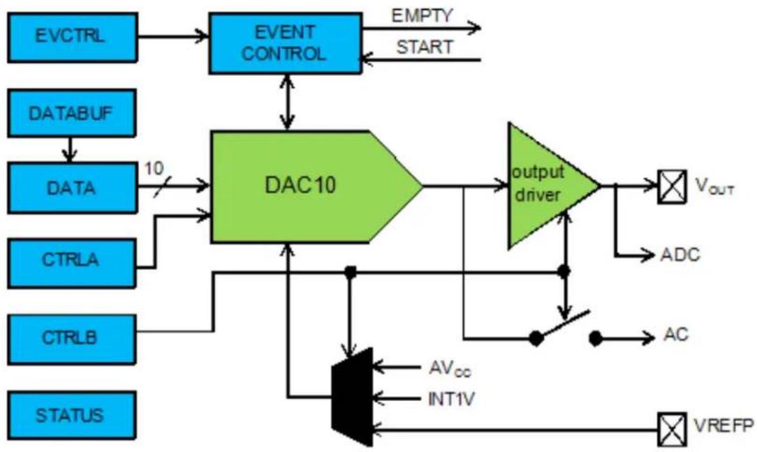
flowchart
graph TD
    A["EVCTRL"] --> B["EVENT CONTROL"]
    C["DATABUF"] --> D["DATA"]
    D --> E["10"]
    E --> F["DAC10"]
    G["CTRLA"] --> F
    H["CTRLB"] --> F
    I["STATUS"] --> F
    F --> J["output driver"]
    J --> K["VOUT"]
    J --> L["ADC"]
    J --> M["AC"]
    J --> N["VREFP"]
    O["AVcc"] --> P["AND"]
    Q["INT1V"] --> P
    P --> R["AND"]
    S["OUTPUT"] --> T["AND"]
    U["OUTPUT"] --> V["AND"]
    W["OUTPUT"] --> X["AND"]
    Y["OUTPUT"] --> Z["AND"]
    AA["OUTPUT"] --> AB["AND"]
    AC["OUTPUT"] --> AD["AND"]
    AE["OUTPUT"] --> AF["AND"]
    AG["OUTPUT"] --> AH["AND"]
    AI["OUTPUT"] --> AJ["AND"]
    AK["OUTPUT"] --> AL["AND"]
    AM["OUTPUT"] --> AN["AND"]
    AO["OUTPUT"] --> AP["AND"]
    AQ["OUTPUT"] --> AR["AND"]
    AS["OUTPUT"] --> AT["AND"]
    AU["OUTPUT"] --> AV["AND"]
    AW["OUTPUT"] --> AX["AND"]
    AY["EMPTY START"] --> AZ["OUTPUT"]
4.2.1 Conversion Range
The conversion range is between GND and the selected voltage reference. Available voltage references are:
• AVCC voltage reference
• Internal 1V reference (INT1V)
• External voltage reference (AREF)
Note
Internal references will be enabled by the driver, but not disabled. Any reference not used by the application should be disabled by the application.
The output voltage from a DAC channel is given as:
$$ V _ {O U T} = \frac {D A T A}{0 x 3 F F} \times V R E F \tag {4.1} $$
4.2.2 Conversion
The digital value written to the conversion data register (DATA) will be converted to an analog value. Writing the DATA register will start a new conversion. It is also possible to write the conversion data to the DATABUF register, the writing of the DATA register can then be triggered from the event system, which will load the value from DATABUF to DATA.
4.2.3 Analog Output
The analog output value can be output to either the VOUT pin or internally, but not both at the same time.
4.2.3.1 External Output
The output buffer must be enabled in order to drive the DAC output to the VOUT pin. Due to the output buffer, the DAC has high drive strength, and is capable of driving both resistive and capacitive loads, as well as loads which combine both.
4.2.3.2 Internal Output
The analog value can be internally available for use as input to the AC or ADC modules.
4.2.4 Events
Events generation and event actions are configurable in the DAC. The DAC has one event line input and one event output: Start Conversion and Data Buffer Empty.
If the Start Conversion input event is enabled in the module configuration, an incoming event will load data from the data buffer to the data register and start a new conversion. This method synchronizes conversions with external events (such as those from a timer module) and ensures regular and fixed conversion intervals.
If the Data Buffer Empty output event is enabled in the module configuration, events will be generated when the DAC data buffer register becomes empty and new data can be loaded to the buffer.
Note
The connection of events between modules requires the use of the SAM D20/D21 Event System Driver (EVENTS) to route output event of one module to the input event of another. For more information on event routing, refer to the event driver documentation.
4.2.5 Left and Right Adjusted Values
The 10-bit input value to the DAC is contained in a 16-bit register. This can be configured to be either left or right adjusted. In Figure 4-2: Left and Right Adjusted Values on page 91 both options are shown, and the position of the most (MSB) and the least (LSB) significant bits are indicated. The unused bits should always be written to zero.
Figure 4-2. Left and Right Adjusted Values
Left a djuste d. Right adjusted.
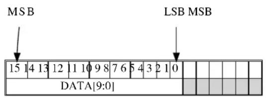
text_image
MSB LSB MSB 15 14 13 12 11 10 9 8 7 6 5 4 3 2 1 0 DATA[9:0]
text_image
LSB 15 14 13 12 11 10 9 8 7 6 5 4 3 2 1 0 DATA[9:0]4.2.6 Clock Sources
The clock for the DAC interface (CLK_DAC) is generated by the Power Manager. This clock is turned on by default, and can be enabled and disabled in the Power Manager.
Additionally, an asynchronous clock source (GCLK_DAC) is required. These clocks are normally disabled by default. The selected clock source must be enabled in the Power Manager before it can be used by the DAC. The DAC core operates asynchronously from the user interface and peripheral bus. As a consequence, the DAC needs two clock cycles of both CLK_DAC and GCLK_DAC to synchronize the values written to some of the control and data registers. The oscillator source for the GCLK_DAC clock is selected in the System Control Interface (SCIF).
4.3 Special Considerations
4.3.1 Output Driver
The DAC can only do conversions in Active or Idle modes. However, if the output buffer is enabled it will draw current even if the system is in sleep mode. Therefore, always make sure that the output buffer is not enabled when it is not needed, to ensure minimum power consumption.
4.3.2 Conversion Time
DAC conversion time is approximately 2.85us. The user must ensure that new data is not written to the DAC before the last conversion is complete. Conversions should be triggered by a periodic event from a Timer/Counter or another peripheral.
4.4 Extra Information
For extra information see Extra Information for DAC Driver. This includes:
• Acronyms
- Dependencies
- Errata
- Module History
4.5 Examples
For a list of examples related to this driver, see Examples for DAC Driver.
4.6 API Overview
4.6.1 Variable and Type Definitions
4.6.1.1 Type dac_callback_t
typedef void(* dac_callback_t )(uint8_t channel)
Type definition for a DAC module callback function.
4.6.2 Structure Definitions
4.6.2.1 Struct dac_chan_config
Configuration for a DAC channel. This structure should be initialized by the dac_chan_get_config_defaults() function before being modified by the user application.
4.6.2.2 Struct dac_config
Configuration structure for a DAC instance. This structure should be initialized by the dac_get_config_defaults() function before being modified by the user application.
Table 4-1. Members
| Type Name Description | ||
| enum gclk_generator clock_source GCLK generator used to clock the | peripheral | |
| bool left_adjust Left adjusted data | ||
| enum dac_output output Select DAC output | ||
| enum dac_reference reference Reference voltage | ||
| bool run_in_standby The DAC behaves as in normal | mode when the chip enters STANDBY sleep mode | |
| bool voltage_pump_disable | Voltage pump disable |
4.6.2.3 Struct dac_events
Event flags for the DAC module. This is used to enable and disable events via dac_enable_events() and dac_disable_events().
Table 4-2. Members
| Type Name Description | ||
| bool generate_event_on_buffer_empty Enable event generation on data | buffer empty | |
| bool on_event_start_conversion Start a new DAC conversion | ||
4.6.2.4 Struct dac\_module
DAC software instance structure, used to retain software state information of an associated hardware module instance.
Note
The fields of this structure should not be altered by the user application; they are reserved for module-internal use only.
4.6.3 Macro Definitions
4.6.3.1 DAC status flags
DAC status flags, returned by dac_get_status() and cleared by dac_clear_status().
Macro DAC_STATUS_CHANNEL_0_EMPTY
#define DAC_STATUS_CHANNEL_0_EMPTY (1UL << 0)
Data Buffer Empty Channel 0 - Set when data is transferred from DATABUF to DATA by a start conversion event and DATABUF is ready for new data.
Macro DAC_STATUS_CHANNEL_0_UNDERRUN
#define DAC_STATUS_CHANNEL_0_UNDERRUN (1UL << 1)
Under-run Channel 0 - Set when a start conversion event occurs when DATABUF is empty.
4.6.3.2 Macro DAC\_TIMEOUT
#define DAC_TIMEOUT 0xFFFF
Define DAC features set according to different device family
4.6.4 Function Definitions
4.6.4.1 Configuration and Initialization
Function dac_is_syncing()
Determines if the hardware module(s) are currently synchronizing to the bus.
bool dac_is_syncing(
    struct dac_module *const dev_inst)
Checks to see if the underlying hardware peripheral module(s) are currently synchronizing across multiple clock domains to the hardware bus, This function can be used to delay further operations on a module until such time that it is ready, to prevent blocking delays for synchronization in the user application.
Table 4-3. Parameters
| Data direction Parameter name Description | |
| [in] dev_inst Pointer to the DAC software | instance struct |
Returns
Synchronization status of the underlying hardware module(s).
Table 4-4. Return Values
| Return value Description | |
| true if the module has completed synchronization | |
| false if the module synchronization is ongoing |
Function dac\_get\_config\_defaults()
Initializes a DAC configuration structure to defaults.
void dac_get_config_defaults(
    struct dac_config *const config)
Initializes a given DAC configuration structure to a set of known default values. This function should be called on any new instance of the configuration structures before being modified by the user application.
The default configuration is as follows:
• 1V from internal bandgap reference
- Drive the DAC output to the VOUT pin
- Right adjust data
• GCLK generator 0 (GCLK main) clock source
- The output buffer is disabled when the chip enters STANDBY sleep mode
Table 4-5. Parameters
| Data direction Parameter name Description | |
| [out] config Configuration structure to initialize | to default values |
Function dac\_init()
Initialize the DAC device struct.
enum status_code dac_init(
    struct dac_module *const dev_inst,
    Dac *const module,
    struct dac_config *const config)
Use this function to initialize the Digital to Analog Converter. Resets the underlying hardware module and configures it.
Note
The DAC channel must be configured separately.
Table 4-6. Parameters
| Data direction Parameter name Description | |
| [out] module_inst Pointer to the DAC software | instance struct |
| [in] module Pointer to the DAC module | instance |
| [in] config Pointer to the config struct, created | by the user application |
Returns
Status of initialization
Table 4-7. Return Values
| Return value Description | |
| STATUS_OK Module initiated correctly | |
| STATUS_ERR_DENIED If module is enabled | |
| STATUS_BUSY If module is busy resetting |
Function dac\_reset()
Resets the DAC module.
void dac_reset(
    struct dac_module *const dev_inst)
This function will reset the DAC module to its power on default values and disable it.
Table 4-8. Parameters
| Data direction Parameter name Description | |
| [in] module_inst Pointer to the DAC software | instance struct |
Function dac\_enable()
Enable the DAC module.
void dac_enable(
    struct dac_module *const dev_inst)
Enables the DAC interface and the selected output. If any internal reference is selected it will be enabled.
Table 4-9. Parameters
| Data direction Parameter name Description | |
| [in] module_inst Pointer to the DAC software | instance struct |
Function dac\_disable()
Disable the DAC module.
void dac_disable(
    struct dac_module *const dev_inst)
Disables the DAC interface and the output buffer.
Table 4-10. Parameters
| Data direction Parameter name Description | |
| [in] module_inst Pointer to the DAC software | instance struct |
Function dac\_enable\_events()
Enables a DAC event input or output.
void dac_enable_events(
    struct dac_module *const module_inst,
    struct dac_events *const events)
Enables one or more input or output events to or from the DAC module. See here for a list of events this module supports.
Note
Events cannot be altered while the module is enabled.
Table 4-11. Parameters
| Data direction Parameter name Description | |
| [in] module_inst Software instance for the DAC | peripheral |
| [in] events Struct containing flags of events to | enable |
Function dac\_disable\_events()
Disables a DAC event input or output.
void dac_disable_events(
    struct dac_module *const module_inst,
    struct dac_events *const events)
Disables one or more input or output events to or from the DAC module. See here for a list of events this module supports.
Note
Events cannot be altered while the module is enabled.
Table 4-12. Parameters
| Data direction Parameter name Description | |
| [in] module_inst Software instance for the DAC | peripheral |
| [in] events Struct containing flags of events to | disable |
4.6.4.2 Configuration and Initialization (Channel)
Function dac\_chan\_get\_config\_defaults()
Initializes a DAC channel configuration structure to defaults.
void dac_chan_get_config_defaults(
    struct dac_chan_config *const config)
Initializes a given DAC channel configuration structure to a set of known default values. This function should be called on any new instance of the configuration structures before being modified by the user application.
The default configuration is as follows:
- Start Conversion Event Input enabled
- Start Data Buffer Empty Event Output disabled
Table 4-13. Parameters
| Data direction Parameter name Description | |
| [out] config Configuration structure to initialize | to default values |
Function dac\_chan\_set\_config()
Writes a DAC channel configuration to the hardware module.
void dac_chan_set_config(
    struct dac_module *const dev_inst,
    const enum dac_channel channel,
struct dac_chan_config *const config)
Writes out a given channel configuration to the hardware module.
Note
The DAC device instance structure must be initialized before calling this function.
Table 4-14. Parameters
| Data direction Parameter name Description | |
| [in] module_inst Pointer to the DAC software | instance struct |
| [in] channel Channel to configure | |
| [in] config Pointer to the configuration struct |
Function dac\_chan\_enable()
Enable a DAC channel.
void dac_chan_enable(
    struct dac_module *const dev_inst,
    enum dac_channel channel)
Enables the selected DAC channel.
Table 4-15. Parameters
| Data direction Parameter name Description | |
| [in] module_inst Pointer to the DAC software | instance struct |
| [in] channel Channel to enable |
Function dac\_chan\_disable()
Disable a DAC channel.
void dac_chan_disable(
    struct dac_module *const dev_inst,
    enum dac_channel channel)
Disables the selected DAC channel.
Table 4-16. Parameters
| Data direction Parameter name Description | |
| [in] module_inst Pointer to the DAC software | instance struct |
| [in] channel Channel to disable |
Function dac_chan_enable_output_buffer()
Enable the output buffer.
void dac_chan_enable_output_buffer( struct dac_module *const dev_inst, const enum dac_channel channel)
Enables the output buffer and drives the DAC output to the VOUT pin.
Table 4-17. Parameters
| Data direction Parameter name Description | |
| [in] module_inst Pointer to the DAC software | instance struct |
| [in] channel DAC channel to alter |
Function dac\_chan\_disable\_output\_buffer()
Disable the output buffer.
void dac_chan_disable_output_buffer( struct dac_module *const dev_inst, const enum dac_channel channel)
Disables the output buffer.
Note
The output buffer(s) should be disabled when a channel's output is not currently needed, as it will draw current even if the system is in sleep mode.
Table 4-18. Parameters
| Data direction Parameter name Description | |
| [in] module_inst Pointer to the DAC software | instance struct |
| [in] channel DAC channel to alter |
4.6.4.3 Channel Data Management
Function dac\_chan\_write()
Write to the DAC.
enum status_code dac_chan_write(
    struct dac_module *const dev_inst,
    enum dac_channel channel,
    const uint16_t data)
This function writes to the DATA or DATABUF register. If the conversion is not event-triggered, the data will be written to the DATA register and the conversion will start. If the conversion is event-triggered, the data will be written to DATABUF and transferred to the DATA register and converted when a Start Conversion Event is issued. Conversion data must be right or left adjusted according to configuration settings.
Note
To be event triggered, the enable_start_on_event must be enabled in the configuration.
Table 4-19. Parameters
| Data direction Parameter name Description | |
| [in] module_inst Pointer to the DAC software device | struct |
| [in] channel DAC channel to write to | |
| [in] data Conversion data |
Returns
Status of the operation
Table 4-20. Return Values
| Return value Description | |
| STATUS_OK If the data was written |
Function dac\_chan\_write\_buffer\_wait()
Write to the DAC.
enum status_code dac_chan_write_buffer_wait(
    struct dac_module *const module_inst,
    enum dac_channel channel,
    uint16_t * buffer,
    uint32_t length)
This function converts a specific number of digital data. The conversion should be event-triggered, the data will be written to DATABUF and transferred to the DATA register and converted when a Start Conversion Event is issued. Conversion data must be right or left adjusted according to configuration settings.
Note
To be event triggered, the enable_start_on_event must be enabled in the configuration.
Table 4-21. Parameters
| Data direction Parameter name Description | ||
| [in] module_inst Pointer to the DAC software device | struct | |
| [in] channel DAC channel to write to | ||
| [in] buffer Pointer to the digital data write | buffer to be converted | |
| [in] length Length of the write buffer |
Returns
Status of the operation
Table 4-22. Return Values
| Return value Description | |
| STATUS_OK If the data was written or no data conversion required | |
| STATUS_ERR_UNSUPPORTED_DEV The DAC is not configured as using event trigger. | |
| STATUS_BUSY The DAC is busy to convert. | |
4.6.4.4 Status Management
Function dac\_get\_status()
Retrieves the current module status.
uint32_t dac_get_status(
    struct dac_module *const module_inst)
Checks the status of the module and returns it as a bitmask of status flags
Table 4-23. Parameters
| Data direction Parameter name Description | |
| [in] module_inst Pointer to the DAC software device | struct |
Returns
Bitmask of status flags
Table 4-24. Return Values
| Return value Description | |
| DAC_STATUS_CHANNEL_0_EMPTY Data has been transferred from DATABUF to DATA by a start conversion event and DATABUF is ready for new data. | |
| DAC_STATUS_CHANNEL_0_UNDERRUN A start conversion event has occurred when DATABUF is empty | |
Function dac\_clear\_status()
Clears a module status flag.
void dac_clear_status(
    struct dac_module *const module_inst,
    uint32_t status_flags)
Clears the given status flag of the module.
Table 4-25. Parameters
| Data direction Parameter name Description | |
| [in] module_inst Pointer to the DAC software device | struct |
| [in] status_flags Bit mask of status flags to clear |
4.6.4.5 Callback configuration and initialization
Function dac\_chan\_write\_buffer\_job()
Convert a specific number digital data to analog through DAC.
enum status_code dac_chan_write_buffer_job(
    struct dac_module *const module_inst,
    const uint32_t channel,
    uint16_t * buffer,
    uint32_t buffer_size)
This function will perform a conversion of specific number of digital data. The conversion should be event-triggered, the data will be written to DATABUF and transferred to the DATA register and converted when a Start Conversion Event is issued. Conversion data must be right or left adjusted according to configuration settings.
Note
To be event triggered, the enable_start_on_event must be enabled in the configuration.
Table 4-26. Parameters
| Data direction Parameter name Description | |
| [in] module_inst Pointer to the DAC software device | struct |
| [in] channel DAC channel to write to | |
| [in] buffer Pointer to the digital data write | buffer to be converted |
| [in] length Size of the write buffer |
Returns
Status of the operation
Table 4-27. Return Values
| Return value Description | |
| STATUS_OK If the data was written | |
| STATUS_ERR_UNSUPPORTED_DEV If a callback that requires event driven mode was specified with a DAC instance configured in non-event mode. | |
| STATUS_BUSY The DAC is busy to accept new job. | |
Function dac\_chan\_write\_job()
Convert one digital data job.
enum status_code dac_chan_write_job(
    struct dac_module *const module_inst,
    const uint32_t channel,
    uint16_t data)
This function will perform a conversion of specific number of digital data. The conversion is event-triggered, the data will be written to DATABUF and transferred to the DATA register and converted when a Start Conversion Event is issued. Conversion data must be right or left adjusted according to configuration settings.
Note
To be event triggered, the enable_start_on_event must be enabled in the configuration.
Table 4-28. Parameters
| Data direction Parameter name Description | |
| [in] module_inst Pointer to the DAC software device | struct |
| [in] channel DAC channel to write to | |
| [in] data Digital data to be converted |
Returns
Status of the operation
Table 4-29. Return Values
| Return value Description | |
| STATUS_OK If the data was written | |
| STATUS_ERR_UNSUPPORTED_DEV If a callback that requires event driven mode was specified with a DAC instance configured in non-event mode. | |
| STATUS_BUSY The DAC is busy to accept new job. | |
Function dac\_register\_callback()
Registers an asynchronous callback function with the driver.
enum status_code dac_register_callback(
    struct dac_module *const module,
    const uint32_t channel,
    const dac_callback_t callback,
    const enum dac_callback type)
Registers an asynchronous callback with the DAC driver, fired when a callback condition occurs.
Table 4-30. Parameters
| Data direction Parameter name Description | |
| [in, out] module_inst Pointer to the DAC software | instance struct |
| [in] callback Pointer to the callback function to | register |
| [in] channel Logical channel to register | callback function |
| [in] type Type of callback function to register |
Returns
Status of the registration operation.
Table 4-31. Return Values
| Return value Description | |
| STATUS_OK The callback was registered successfully. | |
| STATUS_ERR_INVALID_ARG If an invalid callback type was supplied. | |
| STATUS_ERR_UNSUPPORTED_DEV If a callback that requires event driven mode was specified with a DAC instance configured in non-event mode. | |
Function dac\_unregister\_callback()
Unregisters an asynchronous callback function with the driver.
enum status_code dac_unregister_callback(
    struct dac_module *const module,
    const uint32_t channel,
    const enum dac_callback type)
Unregisters an asynchronous callback with the DAC driver, removing it from the internal callback registration table.
Table 4-32. Parameters
| Data direction Parameter name Description | |
| [in, out] module_inst Pointer to the DAC software | instance struct |
| [in] channel Logical channel to unregiseter | callback function |
| [in] type Type of callback function to | unregister |
Returns
Status of the de-registration operation.
Table 4-33. Return Values
| Return value Description | |
| STATUS_OK The callback was unregistered successfully. | |
| STATUS_ERR_INVALID_ARG If an invalid callback type was supplied. | |
| STATUS_ERR_UNSUPPORTED_DEV If a callback that requires event driven mode was specified with a DAC instance configured in non-event mode. | |
4.6.4.6 Callback enabling and disabling (Channel)
Function dac\_chan\_enable\_callback()
Enables asynchronous callback generation for a given channel and type.
enum status_code dac_chan_enable_callback(
    struct dac_module *const module,
    const uint32_t channel,
    const enum dac_callback type)
Enables asynchronous callbacks for a given logical DAC channel and type. This must be called before a DAC channel will generate callback events.
Table 4-34. Parameters
| Data direction Parameter name Description | |
| [in, out] dac_module Pointer to the DAC software | instance struct |
| [in] channel Logical channel to enable callback | function |
| [in] type Type of callback function callbacks | to enable |
Returns
Status of the callback enable operation.
Table 4-35. Return Values
| Return value Description | |
| STATUS_OK The callback was enabled successfully. | |
| STATUS_ERR_UNSUPPORTED_DEV If a callback that requires event driven mode was specified with a DAC instance configured in non-event mode. | |
Function dac\_chan\_disable\_callback()
Disables asynchronous callback generation for a given channel and type.
enum status_code dac_chan_disable_callback(
    struct dac_module *const module,
    const uint32_t channel,
    const enum dac_callback type)
Disables asynchronous callbacks for a given logical DAC channel and type.
Table 4-36. Parameters
| Data direction Parameter name Description | |
| [in, out] dac_module Pointer to the DAC software | instance struct |
| [in] channel Logical channel to disable callback | function |
| [in] type Type of callback function callbacks | to disable |
Returns
Status of the callback disable operation.
Table 4-37. Return Values
| Return value Description | |
| STATUS_OK The callback was disabled successfully. | |
| STATUS_ERR_UNSUPPORTED_DEV If a callback that requires event driven mode was specified with a DAC instance configured in non-event mode. | |
Function dac\_get\_job\_status()
Gets the status of a job.
enum status_code dac_get_job_status( struct dac_module * module_inst)
Gets the status of an ongoing or the last job.
Table 4-38. Parameters
| Data direction Parameter name Description | |
| [in] module_inst Pointer to the DAC software | instance struct |
Returns
Status of the job
Function dac\_abort\_job()
Aborts an ongoing job.
void dac_abort_job(
    struct dac_module * module_inst)
Aborts an ongoing job.
Table 4-39. Parameters
| Data direction Parameter name Description | |
| [in] module_inst Pointer to the DAC software | instance struct |
4.6.5 Enumeration Definitions
4.6.5.1 Enum dac_callback
Enum for the possible callback types for the DAC module.
Table 4-40. Members
| Enum value Description | |
| DAC_CALLBACK_DATA_EMPTY Callback type for when a DAC channel data empty condition occurs (requires event triggered mode). | |
| DAC_CALLBACK_DATA_UNDERRUN Callback type for when a DAC channel data under-run condition occurs (requires event triggered mode). | |
| DAC_CALLBACK_TRANSFER_COMPLETE Callback type for when a DAC channel write buffer job complete. (requires event triggered mode). | |
4.6.5.2 Enum dac\_channel
Enum for the DAC channel selection.
Table 4-41. Members
| Enum value Description | |
| DAC_CHANNEL_0 DAC output channel 0. |
4.6.5.3 Enum dac\_output
Enum for the DAC output selection.
Table 4-42. Members
| Enum value Description | |
| DAC_OUTPUT_EXTERNAL DAC output to VOUT pin | |
| DAC_OUTPUT_INTERNAL DAC output as internal reference | |
| DAC_OUTPUT_NONE No output |
4.6.5.4 Enum dac\_reference
Enum for the possible reference voltages for the DAC.
Table 4-43. Members
| Enum value Description | |
| DAC_REFERENCE_INT1V 1V from the internal band-gap reference. | |
| DAC_REFERENCE_AVCC Analog VCC as reference. | |
| DAC_REFERENCE_AREF External reference on AREF. | |
4.7 Extra Information for DAC Driver
4.7.1 Acronyms
The table below presents the acronyms used in this module:
| Acronym Description | |
| ADC | Analog-to-Digital Converter |
| AC Analog Comparator | |
| DAC Digital-to-Analog Converter | |
| LSB Least Significant Bit | |
| MSB Most Significant Bit | |
| DMA Direct Memory Access |
4.7.2 Dependencies
This driver has the following dependencies:
• System Pin Multiplexer Driver
4.7.3 Errata
There are no errata related to this driver.
4.7.4 Module History
An overview of the module history is presented in the table below, with details on the enhancements and fixes made to the module since its first release. The current version of this corresponds to the newest version in the table.
Changelog
Added new configuration parameters databuf_protection_bypass, voltage_pump_disable. Added new callback functions dac_chan_write_buffer_wait, dac_chan_write_buffer_job, dac_chan_write_job, dac_get_job_status, dac_abort_job and new callback type DAC_CALLBACK_TRANSFER_COMPLETE for DAC conversion job
Initial Release
4.8 Examples for DAC Driver
This is a list of the available Quick Start guides (QSGs) and example applications for SAM D20/D21 Digital-to-Analog Driver (DAC). QSGs are simple examples with step-by-step instructions to configure and use this driver in a selection of use cases. Note that QSGs can be compiled as a standalone application or be added to the user application.
- Quick Start Guide for DAC - Basic
- Quick Start Guide for DAC - Callback
- Quick Start Guide for Using DMA with ADC/DAC
4.8.1 Quick Start Guide for DAC - Basic
In this use case, the DAC will be configured with the following settings:
• Analog VCC as reference
• Internal output disabled
- Drive the DAC output to the V OUT pin
- Right adjust data
- The output buffer is disabled when the chip enters STANDBY sleep mode
4.8.1.1 Quick Start
Prerequisites
There are no special setup requirements for this use-case.
Code
Add to the main application source file, outside of any functions:
struct dac_module dac_instance;
Copy-paste the following setup code to your user application:
void configure_dac(void)
{
    struct dac_config config_dac;
    dac_get_config_defaults(&config_dac);

    dac_init(&dac_instance, DAC, &config_dac);

    dac_enable(&dac_instance);
}

void configure_dac_channel(void)
{
    struct dac_chan_config config_dac_chan;
    dac_chan_get_config_defaults(&config_dac_chan);

    dac_chan_set_config(&dac_instance, DAC_CHANNEL_0, &config_dac_chan);

    dac_chan_enable(&dac_instance, DAC_CHANNEL_0);
}
Add to user application initialization (typically the start of main()):
configure_dac();
configure_dac_channel();
Workflow
- Create a module software instance structure for the DAC module to store the DAC driver state while it is in use.
struct dac_module dac_instance;
Note
This should never go out of scope as long as the module is in use. In most cases, this should be global.
- Configure the DAC module.
a. Create a DAC module configuration struct, which can be filled out to adjust the configuration of a physical DAC peripheral.
struct dac_config config_dac;
b. Initialize the DAC configuration struct with the module's default values.
dac_get_config_defaults(&config_dac);
Note
This should always be performed before using the configuration struct to ensure that all values are initialized to known default settings.
c. Enable the DAC module so that channels can be configured.
dac_enable(&dac_instance);
- Configure the DAC channel.
a. Create a DAC channel configuration struct, which can be filled out to adjust the configuration of a physical DAC output channel.
struct dac_chan_config config_dac_chan;
b. Initialize the DAC channel configuration struct with the module's default values.
dac_chan_get_config_defaults(&config_dac_chan);
Note
This should always be performed before using the configuration struct to ensure that all values are initialized to known default settings.
c. Configure the DAC channel with the desired channel settings.
dac_chan_set_config(&dac_instance, DAC_CHANNEL_0, &config_dac_chan);
d. Enable the DAC channel so that it can output a voltage.
dac_chan_enable(&dac_instance, DAC_CHANNEL_0);
4.8.1.2 Use Case
Code
Copy-paste the following code to your user application:
uint16_t i = 0;
while (1) {
    dac_chan_write(&dac_instance, DAC_CHANNEL_0, i);
    if (++i == 0x3FF) {
    i = 0;
    }
}
Workflow
- Create a temporary variable to track the current DAC output value.
uint16_t i = 0;
- Enter an infinite loop to continuously output new conversion values to the DAC.
while (1) {
- Write the next conversion value to the DAC, so that it will be output on the device's DAC analog output pin.
dac_chan_write(&dac_instance, DAC_CHANNEL_0, i);
- Increment and wrap the DAC output conversion value, so that a ramp pattern will be generated.
if (++i == 0x3FF) {
    i = 0;
}
4.8.2 Quick Start Guide for DAC - Callback
In this use case, the DAC will be convert 16 samples using interrupt driven conversion. When all samples have been sampled, a callback will be called that signals the main application that conversion is compete.
The DAC will be set up as follows:
• Analog VCC as reference
- Internal output disabled
- Drive the DAC output to the V OUT pin
- Right adjust data
- The output buffer is disabled when the chip enters STANDBY sleep mode
• DAC conversion is started with RTC overflow event
4.8.2.1 Setup
Prerequisites
There are no special setup requirements for this use-case.
Code
Add to the main application source file, outside of any functions:
#define DATA_LENGTH (16)
struct dac_module dac_instance;
struct rtc_module rtc_instance;
struct events_resource event_dac;
static volatile bool transfer_is_done = false;
static uint16_t dac_data[DATA_LENGTH];
Callback function:
void dac_callback(uint8_t channel)
{
    UNUSED(channel);
    transfer_is_done = true;
}
Copy-paste the following setup code to your user application:
void configure_rtc_count(void)
{
    struct rtc_count_events   rtc_event;

    struct rtc_count_config config_rtc_count;

    rtc_count_get_config_defaults(&config_rtc_count);

    config_rtc_count.prescaler = RTC_COUNT_PRESCALER_DIV_1;
    config_rtc_count.mode = RTC_COUNT_MODE_16BIT;
    config_rtc_count.continuously_update = true;

    rtc_count_init(&rtc_instance, RTC, &config_rtc_count);

    rtc_event.generate_event_on_overflow = true;

    rtc_count_enable_events(&rtc_instance, &rtc_event);

    rtc_count_enable(&rtc_instance);
}
void configure_dac(void)
{
    struct dac_config config_dac;
    dac_get_config_defaults(&config_dac);
    dac_instance.start_on_event = true;
    dac_init(&dac_instance, DAC, &config_dac);
    struct dac_events events = { .on_event_start_conversion = true };
    dac_enable_events(&dac_instance, &events);
    dac_enable(&dac_instance);
}
void configure_dac_channel(void)
{
struct dac_chan_config config_dac_chan;
dac_chan_get_config_defaults(&config_dac_chan);
dac_chan_set_config(&dac_instance, DAC_CHANNEL_0, &config_dac_chan);
dac_chan_enable(&dac_instance, DAC_CHANNEL_0);
define a data length variables and add to user application (typically the start of main()):
uint32_t i;
Add to user application initialization (typically the start of main()):
configure_rtc_count();
rtc_count_set_period(&rtc_instance,1);
configure_dac();
configure_dac_channel();
configure_event_resource();
dac_register_callback(&dac_instance, DAC_CHANNEL_0, dac_callback, DAC_CALLBACK_TRANSFER_COMPLETE);
dac_chan_enable_callback(&dac_instance, DAC_CHANNEL_0, DAC_CALLBACK_TRANSFER_COMPLETE);
for (i=0;i<DATA_LENGTH;i++) {
    dac_data[i] = 0xfff*i;
}
Workflow
- Create a module software instance structure for the DAC module to store the DAC driver state while it is in use.
struct dac_module dac_instance;
Note
This should never go out of scope as long as the module is in use. In most cases, this should be global.
- RTC module is used as the event trigger for DAC in this case, create a module software instance structure for the RTC module to store the RTC driver state.
struct rtc_module rtc_instance;
Note
This should never go out of scope as long as the module is in use. In most cases, this should be global.
- Create a buffer for the DAC samples to be converted by the driver.
static uint16_t dac_data[DATA_LENGTH];
- Create a callback function that will be called when DAC completes convert job.
void dac_callback(uint8_t channel)
{
    UNUSED(channel);
    transfer_is_done = true;
}
- Configure the DAC module.
a. Create a DAC module configuration struct, which can be filled out to adjust the configuration of a physical DAC peripheral.
struct dac_config config_dac;
b. Initialize the DAC configuration struct with the module's default values.
dac_get_config_defaults(&config_dac);
Note
This should always be performed before using the configuration struct to ensure that all values are initialized to known default settings.
c. Configure the DAC module with starting conversion on event.
dac_instance.start_on_event = true;
d. Initialize the DAC module.
dac_init(&dac_instance, DAC, &config_dac);
e. Enable DAC start on conversion mode.
struct dac_events events = { .on_event_start_conversion = true };
f. Enable DAC event.
dac_enable_events(&dac_instance, &events);
g. Enable DAC module.
dac_enable(&dac_instance);
- Configure the DAC channel.
a. Create a DAC channel configuration struct, which can be filled out to adjust the configuration of a physical DAC output channel.
struct dac_chan_config config_dac_chan;
b. Initialize the DAC channel configuration struct with the module's default values.
dac_chan_get_config_defaults(&config_dac_chan);
Note
This should always be performed before using the configuration struct to ensure that all values are initialized to known default settings.
c. Configure the DAC channel with the desired channel settings.
dac_chan_set_config(&dac_instance, DAC_CHANNEL_0, &config_dac_chan);
d. Enable the DAC channel so that it can output a voltage.
dac_chan_enable(&dac_instance, DAC_CHANNEL_0);
- Configure the RTC module.
a. Create a RTC module event struct, which can be filled out to adjust the configuration of a physical RTC peripheral.
struct rtc_count_events rtc_event;
b. Create a RTC module configuration struct, which can be filled out to adjust the configuration of a physical RTC peripheral.
struct rtc_count_config config_rtc_count;
c. Initialize the RTC configuration struct with the module's default values.
rtc_count_get_config_defaults(&config_rtc_count);
Note
This should always be performed before using the configuration struct to ensure that all values are initialized to known default settings.
d. Change the RTC module configuration to suit the application.
config_rtc_count.prescaler = RTC_COUNT_PRESCALER_DIV_1;
config_rtc_count.mode = RTC_COUNT_MODE_16BIT;
config_rtc_count.continuously_update = true;
e. Initialize the RTC module.
rtc_count_init(&rtc_instance, RTC, &config_rtc_count);
rtc_event.generate_event_on_overflow = true;
g. Enable RTC module overflow event.
rtc_count_enable_events(&rtc_instance, &rtc_event);
h. Enable RTC module.
rtc_count_enable(&rtc_instance);
- Configure the Event resource.
a. Create a event resource config struct, which can be filled out to adjust the configuration of a physical event peripheral.
struct events_config event_config;
b. Initialize the event configuration struct with the module's default values.
events_get_config_defaults(&event_config);
Note
This should always be performed before using the configuration struct to ensure that all values are initialized to known default settings.
c. Change the event module configuration to suit the application.
event_config.generator = EVSYS_ID_GEN_RTC_OVF;
event_config.edge_detect = EVENTS_EDGE_DETECT_RISING;
event_config.path = EVENTS_PATH_ASYNCHRONOUS;
event_config.clock_source = GCLK_GENERATOR_0;
d. Allocate the event resource.
events_allocate(&event_dac, &event_config);
e. Attach the event resource with user DAC start
events_attach_user(&event_dac, EVSYS_ID_USER_DAC_START);
- Register and enable the DAC Write Buffer Complete callback handler
a. Register the user-provided Write Buffer Complete callback function with the driver, so that it will be run when an asynchronous buffer write job completes.
dac_register_callback(&dac_instance, DAC_CHANNEL_0, dac_callback, DAC_CALLBACK_TRANSFER_COMPLETE);
b. Enable the Read Buffer Complete callback so that it will generate callbacks.
dac_chan_enable_callback(&dac_instance, DAC_CHANNEL_0, DAC_CALLBACK_TRANSFER_COMPLETE);
4.8.2.2 Use Case
Code
Copy-paste the following code to your user application:
dac_chan_write_buffer_job(&dac_instance, DAC_CHANNEL_0, dac_data, DATA_LENGTH);

while (!transfer_is_done) {
    /* Wait for transfer done */
}

while (1) {
}
Workflow
- Start an DAC conversion and generate a callback when complete.
dac_chan_write_buffer_job(&dac_instance, DAC_CHANNEL_0, dac_data, DATA_LENGTH);
- Wait until the conversion is complete.
while (!transfer_is_done) {
    /* Wait for transfer done */
}
- Enter an infinite loop once the conversion is complete.
while (1) { }
4.8.3 Quick Start Guide for Using DMA with ADC/DAC
For this examples, see Quick Start Guide for Using DMA with ADC/DAC
5. SAM D20/D21 EEPROM Emulator Service (EEPROM)
This driver for SAM D20/D21 devices provides an emulated EEPROM memory space in the device's FLASH memory, for the storage and retrieval of user-application configuration data into and out of non-volatile memory.
The following peripherals are used by this module:
• NVM (Non-Volatile Memory Controller)
The outline of this documentation is as follows:
- Prerequisites
- Module Overview
• Special Considerations
- Extra Information
- Examples
- API Overview
5.1 Prerequisites
The SAM D20/D21 device fuses must be configured via an external programmer or debugger, so that an EEPROM section is allocated in the main NVM flash memory contents. If a NVM section is not allocated for the EEPROM emulator, or if insufficient space for the emulator is reserved, the module will fail to initialize.
5.2 Module Overview
As the SAM D20/D21 devices do not contain any physical EEPROM memory, the storage of non-volatile user data is instead emulated using a special section of the device's main FLASH memory. The use of FLASH memory technology over EEPROM presents several difficulties over true EEPROM memory; data must be written as a number of physical memory pages (of several bytes each) rather than being individually byte addressable, and entire rows of FLASH must be erased before new data may be stored. To help abstract these characteristics away from the user application an emulation scheme is implemented to present a more user-friendly API for data storage and retrieval.
This module provides an EEPROM emulation layer on top of the device's internal NVM controller, to provide a standard interface for the reading and writing of non-volatile configuration data. This data is placed into the EEPROM emulated section of the device's main FLASH memory storage section, the size of which is configured using the device's fuses. Emulated EEPROM is exempt from the usual device NVM region lock bits, so that it may be read from or written to at any point in the user application.
There are many different algorithms that may be employed for EEPROM emulation using FLASH memory, to tune the write and read latencies, RAM usage, wear levelling and other characteristics. As a result, multiple different emulator schemes may be implemented, so that the most appropriate scheme for a specific application's requirements may be used.
5.2.1 Implementation Details
The following information is relevant for EEPROM Emulator scheme 1, version 1.0.0, as implemented by this module. Other revisions or emulation schemes may vary in their implementation details and may have different wear-leveling, latency and other characteristics.
5.2.1.1 Emulator Characteristics
This emulator is designed for best reliability, with a good balance of available storage and write-cycle limits. It is designed to ensure that page data is atomically updated so that in the event of a failed update the previous data is not lost (when used correctly). With the exception of a system reset with data cached to the internal write-cache buffer, at most only the latest write to physical non-volatile memory will be lost in the event of a failed write.
This emulator scheme is tuned to give best write-cycle longevity when writes are confined to the same logical EEPROM page (where possible) and when writes across multiple logical EEPROM pages are made in a linear fashion through the entire emulated EEPROM space.
5.2.1.2 Physical Memory
The SAM D20/D21 non-volatile FLASH is divided into a number of physical rows, each containing four identically sized flash pages. Pages may be read or written to individually, however pages must be erased before being reprogrammed and the smallest granularity available for erasure is one single row.
This discrepancy results in the need for an emulator scheme that is able to handle the versioning and moving of page data to different physical rows as needed, erasing old rows ready for re-use by future page write operations.
Physically, the emulated EEPROM segment is located at the end of the physical FLASH memory space, as shown in Figure 5-1: Physical Memory on page 119.
Figure 5-1. Physical Memory
| End of N VM Mem ory Start of EEPROM Mem ory End of Applica tion Mem or y | Reserved EEPROM Section |
| Application Section | |
| Start of Application Mem ory End of Bootloader Mem ory Start of NVM Mem ory | BOOT Section |
5.2.1.3 Master Row
One physical FLASH row at the end of the emulated EEPROM memory space is reserved for use by the emulator to store configuration data. The master row is not user-accessible, and is reserved solely for internal use by the emulator.
5.2.1.4 Spare Row
As data needs to be preserved between row erasures, a single FLASH row is kept unused to act as destination for copied data when a write request is made to an already full row. When the write request is made, any logical pages of data in the full row that need to be preserved are written to the spare row along with the new (updated) logical page data, before the old row is erased and marked as the new spare.
5.2.1.5 Row Contents
Each physical FLASH row initially stores the contents of two logical EEPROM memory pages. This halves the available storage space for the emulated EEPROM but reduces the overall number of row erases that are required, by reserving two pages within each row for updated versions of the logical page contents. See Figure 5-3: Initial physical layout of the emulated EEPROM memory on page 120 for a visual layout of the EEPROM Emulator physical memory.
As logical pages within a physical row are updated, the new data is filled into the remaining unused pages in the row. Once the entire row is full, a new write request will copy the logical page not being written to in the current row to the spare row with the new (updated) logical page data, before the old row is erased.
This system allows for the same logical page to be updated up to three times into physical memory before a row erasure procedure is needed. In the case of multiple versions of the same logical EEPROM page being stored in the same physical row, the right-most (highest physical FLASH memory page address) version is considered to be the most current.
5.2.1.6 Write Cache
As a typical EEPROM use case is to write to multiple sections of the same EEPROM page sequentially, the emulator is optimized with a single logical EEPROM page write cache to buffer writes before they are written to the physical backing memory store. The cache is automatically committed when a new write request to a different logical EEPROM memory page is requested, or when the user manually commits the write cache.
Without the write cache, each write request to an EEPROM memory page would require a full page write, reducing the system performance and significantly reducing the lifespan of the non-volatile memory.
5.2.2 Memory Layout
A single logical EEPROM page is physically stored as the page contents and a header inside a single physical FLASH page, as shown in Figure 5-2: Internal layout of an emulated EEPROM page on page 120.
Figure 5-2. Internal layout of an emulated EEPROM page
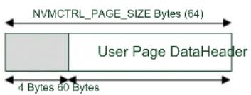
text_image
NVMCTRL_PAGE_SIZE Bytes (64) User Page DataHeader 4 Bytes 60 BytesWithin the EEPROM memory reservation section at the top of the NVM memory space, this emulator will produce the layout as shown in Figure 5-3: Initial physical layout of the emulated EEPROM memory on page 120 when initialized for the first time.
Figure 5-3. Initial physical layout of the emulated EEPROM memory

flowchart
graph TD
    A["MASTER ROW MASTER"] --> B["ROW MASTER ROW MASTER"]
    B --> C["ROW"]
    C --> D["End of Flash"]
    E["Logical Page 0 Revision 0 Logical Page 1 Revision 0"] --> F[" "] --> G[" "] --> H[" "]
    I["Logical Page 2 Revision 0 Logical Page 3 Revision 0"] --> J[" "] --> K[" "] --> L[" "]
    M["Logical Page 4 Revision 0 Logical Page 5 Revision 0"] --> N[" "] --> O[" "] --> P[" "]
    Q["Logical Page 6 Revision 0 Logical Page 7 Revision 0"] --> R[" "] --> S[" "] --> T[" "]
    U["SPARE ROW SPARE"] --> V["ROW SPARE ROW SPARE ROW"]
    V --> W[" "] --> X[" "] --> Y["End of FLASH – EEPROM Rows"]
When an EEPROM page needs to be committed to physical memory, the next free FLASH page in the same row will be chosen - this makes recovery simple, as the right-most version of a logical page in a row is considered the most current. With four pages to a physical NVM row, this allows for up to three updates to the same logical page to be made before an erase is needed. Figure 5-4: First write to logical EEPROM page N-1 on page 121 shows the result of the user writing an updated version of logical EEPROM page N-1 to the physical memory.
Figure 5-4. First write to logical EEPROM page N-1

flowchart
graph TD
    A["MASTER ROW MASTER"] --> B["ROW MASTER ROW MASTER"]
    B --> C["ROW"]
    C --> D["End of Flash"]

    E["Logical Page 0 Revision 0"] --> F["Logical Page 1 Revision 0 Logical"]
    F --> G["Page 0 Revision 1"]

    H["Logical Page 2 Revision 0"] --> I["Logical Page 3 Revision 0"]
    I --> J[" "]
    K["Logical Page 4 Revision 0"] --> L["Logical Page 5 Revision 0"]
    L --> M[" "]
    N["Logical Page 6 Revision 0"] --> O["Logical Page 7 Revision 0"]
    O --> P[" "]
    Q["SPARE ROW SPARE"] --> R["ROW SPARE ROW SPARE ROW"]
    R --> S[" "]
    T["End of FLASH – EEPROM Rows"]
A second write of the same logical EEPROM page results in the layout shown in Figure 5-5: Second write to logical EEPROM page N-1 on page 121.
Figure 5-5. Second write to logical EEPROM page N-1
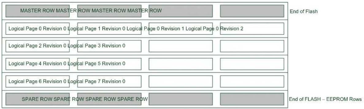
flowchart
graph TD
    A["MASTER ROW MASTER"] --> B["ROW MASTER ROW MASTER"]
    B --> C["ROW"]
    C --> D["End of Flash"]

    E["Logical Page 0 Revision 0"] --> F["Logical Page 1 Revision 0 Logical"]
    F --> G["Page 0 Revision 1 Logical Page 0 Revision 2"]
    G --> H["End of FLASH – EEPROM Rows"]

    I["Logical Page 2 Revision 0"] --> J["Logical Page 3 Revision 0"]
    J --> K[" "] --> L["End of FLASH"]

    M["Logical Page 4 Revision 0"] --> N["Logical Page 5 Revision 0"]
    N --> O[" "] --> P["End of FLASH"]

    Q["Logical Page 6 Revision 0"] --> R["Logical Page 7 Revision 0"]
    R --> S[" "] --> T["End of FLASH"]

    U["SPARE ROW SPARE"] --> V["ROW SPARE ROW SPARE ROW"]
    V --> W[" "] --> X["End of FLASH"]
A third write of the same logical page requires that the EEPROM emulator erase the row, as it has become full. Prior to this, the contents of the unmodified page in the same row as the page being updated will be copied into the spare row, along with the new version of the page being updated. The old (full) row is then erased, resulting in the layout shown in Figure 5-6: Third write to logical EEPROM page N-1 on page 121.
Figure 5-6. Third write to logical EEPROM page N-1
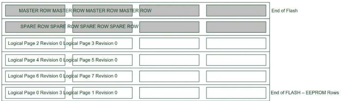
flowchart
graph TD
    A["MASTER ROW MASTER"] --> B["ROW MASTER ROW MASTER"]
    B --> C["ROW"]
    D["SPARE ROW SPARE"] --> E["ROW SPARE ROW SPARE ROW"]
    E --> F[" "]
    G["Logical Page 2 Revision 0"] --> H["Logical Page 3 Revision 0"]
    I["Logical Page 4 Revision 0"] --> J["Logical Page 5 Revision 0"]
    K["Logical Page 6 Revision 0"] --> L["Logical Page 7 Revision 0"]
    M["Logical Page 0 Revision 3"] --> N["Logical Page 1 Revision 0"]
    O["End of Flash"] --> P["End of FLASH – EEPROM Rows"]
5.3 Special Considerations
5.3.1 NVM Controller Configuration
The EEPROM Emulator service will initialize the NVM controller as part of its own initialization routine; the NVM controller will be placed in Manual Write mode, so that explicit write commands must be sent to the controller to commit a buffered page to physical memory. The manual write command must thus be issued to the NVM controller whenever the user application wishes to write to a NVM page for its own purposes.
5.3.2 Logical EEPROM Page Size
As a small amount of information needs to be stored in a header before the contents of a logical EEPROM page in memory (for use by the emulation service), the available data in each EEPROM page is less than the total size of a single NVM memory page by several bytes.
5.3.3 Committing of the Write Cache
A single-page write cache is used internally to buffer data written to pages in order to reduce the number of physical writes required to store the user data, and to preserve the physical memory lifespan. As a result, it is important that the write cache is committed to physical memory as soon as possible after a BOD low power condition, to ensure that enough power is available to guarantee a completed write so that no data is lost.
The write cache must also be manually committed to physical memory if the user application is to perform any NVM operations using the NVM controller directly.
5.4 Extra Information
For extra information see Extra Information. This includes:
- Acronyms
- Dependencies
- Errata
- Module History
5.5 Examples
For a list of examples related to this driver, see Examples for Emulated EEPROM service.
5.6 API Overview
5.6.1 Structure Definitions
5.6.1.1 Struct eeprom_emulator_parameters
Structure containing the memory layout parameters of the EEPROM emulator module.
Table 5-1. Members
| Type Name Description | ||
| uint16_t eeprom_number_of_pages | Number of emulated pages of | EEPROM. |
| uint8_t page_size | Number of bytes per emulated | EEPROM page. |
5.6.2 Macro Definitions
5.6.2.1 EEPROM emulator information
Macro EEPROM_EMULATOR_ID
#define EEPROM_EMULATOR_ID 1
Emulator scheme ID, identifying the scheme used to emulated EEPROM storage.
Macro EEPROM_MAJOR_VERSION
#define EEPROM_MAJOR_VERSION 1
Emulator major version number, identifying the emulator major version.
Macro EEPROM_MINOR_VERSION
#define EEPROM_MINOR_VERSION 0
Emulator minor version number, identifying the emulator minor version.
Macro EEPROM_REVISION
#define EEPROM_REVISION 0
Emulator revision version number, identifying the emulator revision.
Macro EEPROM_PAGE_SIZE
#define EEPROM_PAGE_SIZE (NVMCTRL_PAGE_SIZE - EEPROM_HEADER_SIZE)
Size of the user data portion of each logical EEPROM page, in bytes.
5.6.3 Function Definitions
5.6.3.1 Configuration and initialization
Function eeprom_emulator_init()
Initializes the EEPROM Emulator service.
enum status_code eeprom_emulator_init(void)
Initializes the emulated EEPROM memory space; if the emulated EEPROM memory has not been previously initialized, it will need to be explicitly formatted via eeprom_emulator_erase_memory(). The EEPROM memory space will not be automatically erased by the initialization function, so that partial data may be recovered by the user application manually if the service is unable to initialize successfully.
Returns
Status code indicating the status of the operation.
Table 5-2. Return Values
| Return value Description | |
| STATUS_OK EEPROM emulation service was successfully initialized | |
| STATUS_ERR_NO_MEMORY No EEPROM section has been allocated in the device | |
| STATUS_ERR_BAD_FORMAT Emulated EEPROM memory is corrupt or not formatted | |
| STATUS_ERR_IO EEPROM data is incompatible with this version or scheme of the EEPROM emulator | |
Function eeprom\_emulator\_erase\_memory()
Erases the entire emulated EEPROM memory space.
void eeprom_emulator_erase_memory(void)
Erases and re-initializes the emulated EEPROM memory space, destroying any existing data.
Function eeprom\_emulator\_get\_parameters()
Retrieves the parameters of the EEPROM Emulator memory layout.
enum status_code eeprom_emulator_get_parameters(
    struct eeprom_emulator_parameters *const parameters)
Retrieves the configuration parameters of the EEPROM Emulator, after it has been initialized.
Table 5-3. Parameters
| Data direction Parameter name Description | |
| [out] parameters EEPROM Emulator parameter | struct to fill |
Returns
Status of the operation.
Table 5-4. Return Values
| Return value Description | |
| STATUS_OK If the emulator parameters were retrieved successfully | |
| STATUS_ERR_NOT_INITIALIZED If the EEPROM Emulator is not initialized | |
5.6.3.2 Logical EEPROM page reading/writing
Function eeprom\_emulator\_commit\_page\_buffer()
Commits any cached data to physical non-volatile memory.
enum status_code eeprom_emulator_commit_page_buffer(void)
Commits the internal SRAM caches to physical non-volatile memory, to ensure that any outstanding cached data is preserved. This function should be called prior to a system reset or shutdown to prevent data loss.
Note
This should be the first function executed in a BOD33 Early Warning callback to ensure that any outstanding cache data is fully written to prevent data loss.
This function should also be called before using the NVM controller directly in the user-application for any other purposes to prevent data loss.
Returns
Status code indicating the status of the operation.
Function eeprom\_emulator\_write\_page()
Writes a page of data to an emulated EEPROM memory page.
enum status_code eeprom_emulator_write_page(
    const uint8_t logical_page,
    const uint8_t *const data)
Writes an emulated EEPROM page of data to the emulated EEPROM memory space.
Note
Data stored in pages may be cached in volatile RAM memory; to commit any cached data to physical non-volatile memory, the eeprom_emulator_commit_page_buffer() function should be called.
Table 5-5. Parameters
| Data direction Parameter name Description | |
| [in] logical_page Logical EEPROM page number to | write to |
| [in] data Pointer to the data buffer | containing source data to write |
Returns
Status code indicating the status of the operation.
Table 5-6. Return Values
| Return value Description | |
| STATUS_OK If the page was successfully read | |
| STATUS_ERR_NOT_INITIALIZED If the EEPROM emulator is not initialized | |
| STATUS_ERR_BAD_ADDRESS If an address outside the valid emulated EEPROM memory space was supplied | |
Function eeprom\_emulator\_read\_page()
Reads a page of data from an emulated EEPROM memory page.
enum status_code eeprom_emulator_read_page(
    const uint8_t logical_page,
    uint8_t *const data)
Reads an emulated EEPROM page of data from the emulated EEPROM memory space.
Table 5-7. Parameters
| Data direction Parameter name Description | |
| [in] logical_page Logical EEPROM page number to | read from |
| [out] data Pointer to the destination data | buffer to fill |
Returns
Status code indicating the status of the operation.
Table 5-8. Return Values
| Return value Description | |
| STATUS_OK If the page was successfully read | |
| STATUS_ERR_NOT_INITIALIZED If the EEPROM emulator is not initialized | |
| STATUS_ERR_BAD_ADDRESS If an address outside the valid emulated EEPROM memory space was supplied | |
5.6.3.3 Buffer EEPROM reading/writing
Function eeprom\_emulator\_write\_buffer()
Writes a buffer of data to the emulated EEPROM memory space.
enum status_code eeprom_emulator_write_buffer(
    const uint16_t offset,
    const uint8_t *const data,
    const uint16_t length)
Writes a buffer of data to a section of emulated EEPROM memory space. The source buffer may be of any size, and the destination may lie outside of an emulated EEPROM page boundary.
Note
Data stored in pages may be cached in volatile RAM memory; to commit any cached data to physical non-volatile memory, the eeprom_emulator_commit_page_buffer() function should be called.
Table 5-9. Parameters
| Data direction Parameter name Description | |
| [in] offset Starting byte offset to write to, in | emulated EEPROM memory space |
| [in] data Pointer to the data buffer | containing source data to write |
| [in] length Length of the data to write, in bytes |
Returns
Status code indicating the status of the operation.
Table 5-10. Return Values
| Return value Description | |
| STATUS_OK If the page was successfully read |
| Return value Description | |
| STATUS_ERR_NOT_INITIALIZED If the EEPROM emulator is not initialized | |
| STATUS_ERR_BAD_ADDRESS If an address outside the valid emulated EEPROM memory space was supplied | |
Function eeprom\_emulator\_read\_buffer()
Reads a buffer of data from the emulated EEPROM memory space.
enum status_code eeprom_emulator_read_buffer(
    const uint16_t offset,
    uint8_t *const data,
    const uint16_t length)
Reads a buffer of data from a section of emulated EEPROM memory space. The destination buffer may be of any size, and the source may lie outside of an emulated EEPROM page boundary.
Table 5-11. Parameters
| Data direction Parameter name Description | |
| [in] offset Starting byte offset to read from, in | emulated EEPROM memory space |
| [out] data Pointer to the data buffer | containing source data to read |
| [in] length Length of the data to read, in bytes |
Returns
Status code indicating the status of the operation.
Table 5-12. Return Values
| Return value Description | |
| STATUS_OK If the page was successfully read | |
| STATUS_ERR_NOT_INITIALIZED If the EEPROM emulator is not initialized | |
| STATUS_ERR_BAD_ADDRESS If an address outside the valid emulated EEPROM memory space was supplied | |
5.7 Extra Information
5.7.1 Acronyms
Below is a table listing the acronyms used in this module, along with their intended meanings.
| Acronym Description | |
| EEPROM Electronically Erasable Read-Only Memory | |
| NVM | Non-Volatile Memory |
5.7.2 Dependencies
This driver has the following dependencies:
• Non-Volatile Memory Controller Driver
5.7.3 Errata
There are no errata related to this driver.
5.7.4 Module History
An overview of the module history is presented in the table below, with details on the enhancements and fixes made to the module since its first release. The current version of this corresponds to the newest version in the table.
Changelog
Fix warnings and document for SAM D21
Initial Release
5.8 Examples for Emulated EEPROM service
This is a list of the available Quick Start guides (QSGs) and example applications for SAM D20/D21 EEPROM Emulator Service (EEPROM). QSGs are simple examples with step-by-step instructions to configure and use this driver in a selection of use cases. Note that QSGs can be compiled as a standalone application or be added to the user application.
- Quick Start Guide for the Emulated EEPROM module - Basic Use Case
5.8.1 Quick Start Guide for the Emulated EEPROM module - Basic Use Case
In this use case, the EEPROM emulator module is configured and a sample page of data read and written. The first byte of the first EEPROM page is toggled, and a LED is turned on or off to reflect the new state. Each time the device is reset, the LED should toggle to a different state to indicate correct non-volatile storage and retrieval.
5.8.1.1 Prerequisites
The device's fuses must be configured to reserve a sufficient number of FLASH memory rows for use by the EEPROM emulator service, before the service can be used.
5.8.1.2 Setup
Prerequisites
There are no special setup requirements for this use-case.
Code
Copy-paste the following setup code to your user application:
void configure_eeprom(void)
{
    /* Setup EEPROM emulator service */
    enum status_code error_code = eeprom_emulator_init();

    if (error_code == STATUS_ERR_NO_MEMORY) {
    while (true) {
    /* No EEPROM section has been set in the device's fuses */
    }
    }
    else if (error_code != STATUS_OK) {
    /* Erase the emulated EEPROM memory (assume it is unformatted or
    * irrecoverably corrupt) */
    eeprom_emulator_erase_memory();
    eeprom_emulator_init();
}
Add to user application initialization (typically the start of main()):
configure_eeprom();
Workflow
- Attempt to initialize the EEPROM emulator service, storing the error code from the initialization function into a temporary variable.
enum status_code error_code = EEPROM_emulator_init();
- Check if the emulator failed to initialize due to the device fuses not being configured to reserve enough of the main FLASH memory rows for emulated EEPROM usage - abort if the fuses are mis-configured.
if (error_code == STATUS_ERR_NO_MEMORY) {
    while (true) {
    /* No EEPROM section has been set in the device's fuses */
    }
}
- Check if the emulator service failed to initialize for any other reason; if so assume the emulator physical memory is unformatted or corrupt and erase/re-try initialization.
else if (error_code != STATUS_OK) {
    /* Erase the emulated EEPROM memory (assume it is unformatted or
    * irrecoverably corrupt) */
    eeprom_emulator_erase_memory();
    eeprom_emulator_init();
}
5.8.1.3 Use Case
Code
Copy-paste the following code to your user application:
uint8_t page_data[EEPROM_PAGE_SIZE];
eeprom_emulator_read_page(0, page_data);

page_data[0] = !page_data[0];
port_pin_set_output_level(LED_0_PIN, page_data[0]);

eeprom_emulator_write_page(0, page_data);
eeprom_emulator_commit_page_buffer();

while (true) {

}
Workflow
- Create a buffer to hold a single emulated EEPROM page of memory, and read out logical EEPROM page zero into it.
uint8_t page_data[EEPROM_PAGE_SIZE];
eeprom_emulator_read_page(0, page_data);
- Toggle the first byte of the read page.
page_data[0] = !page_data[0];
- Output the toggled LED state onto the board LED.
port_pin_set_output_level(LED_0_PIN, page_data[0]);
- Write the modified page back to logical EEPROM page zero, flushing the internal emulator write cache afterwards to ensure it is immediately written to physical non-volatile memory.
eeprom_emulator_write_page(0, page_data);
eeprom_emulator_commit_page_buffer();
6. SAM D20/D21 Event System Driver (EVENTS)
This driver for SAM D20/D21 devices provides an interface for the configuration and management of the device's peripheral event resources and users within the device, including enabling and disabling of peripheral source selection and synchronization of clock domains between various modules. The following API modes is covered by this manual:
- Polled API
- Interrupt hook API
The following peripherals are used by this module:
• EVSYS (Event System Management)
The outline of this documentation is as follows:
- Prerequisites
- Module Overview
• Special Considerations - Extra Information
- Examples
- API Overview
6.1 Prerequisites
There are no prerequisites for this module.
6.2 Module Overview
Peripherals within the SAM D20/D21 devices are capable of generating two types of actions in response to given stimulus: set a register flag for later intervention by the CPU (using interrupt or polling methods), or generate event signals which can be internally routed directly to other peripherals within the device. The use of events allows for direct actions to be performed in one peripheral in response to a stimulus in another without CPU intervention. This can lower the overall power consumption of the system if the CPU is able to remain in sleep modes for longer periods (SleepWalking ^™ ), and lowers the latency of the system response.
The event system is comprised of a number of freely configurable Event resources, plus a number of fixed Event Users. Each Event resource can be configured to select the input peripheral that will generate the events signal, as well as the synchronization path and edge detection mode. The fixed-function Event Users, connected to peripherals within the device, can then subscribe to an Event resource in a one-to-many relationship in order to receive events as they are generated. An overview of the event system chain is shown in Figure 6-1: Module Overview on page 132.
Figure 6-1. Module Overview

flowchart
graph LR
    A["Source Peripheral (Generator)"] --> B["Event Resource A"]
    B --> C["Event User X"]
    B --> D["Event User Y"]
    C --> E["De stina tion Peripheral (User)"]
    D --> F["De stina tion Peripheral (User)"]
There are many different events that can be routed in the device, which can then trigger many different actions. For example, an Analog Comparator module could be configured to generate an event when the input signal rises above the compare threshold, which then triggers a Timer Counter module to capture the current count value for later use.
6.2.1 Event Channels
The Event module in each device consists of several channels, which can be freely linked to an event generator (i.e. a peripheral within the device that is capable of generating events). Each channel can be individually configured to select the generator peripheral, signal path and edge detection applied to the input event signal, before being passed to any event user(s).
Event channels can support multiple users within the device in a standardized manner; when an Event User is linked to an Event Channel, the channel will automatically handshake with all attached users to ensure that all modules correctly receive and acknowledge the event.
6.2.2 Event Users
Event Users are able to subscribe to an Event Channel, once it has been configured. Each Event User consists of a fixed connection to one of the peripherals within the device (for example, an ADC module or Timer module) and is capable of being connected to a single Event Channel.
For asynchronous events, edge detection on the event input is not possible, and the event signal must be passed directly between the event generator and event user. For synchronous and re-synchronous events, the input signal from the event generator must pass through an edge detection unit, so that only the rising, falling or both edges of the event signal triggers an action in the event user.
6.2.4 Path Selection
The event system in the SAM D20/D21 devices supports three signal path types from the event generator to event users: asynchronous, synchronous and re-synchronous events.
6.2.4.1 Asynchronous Paths
Asynchronous event paths allow for an asynchronous connection between the event generator and event user(s), when the source and destination peripherals share the same Generic Clock channel. In this mode the event is propagated between the source and destination directly to reduce the event latency, thus no edge detection is possible. The asynchronous event chain is shown in Figure 6-2: Asynchronous Paths on page 133.
Figure 6-2. Asynchronous Paths

flowchart
graph LR
    A["Source Peripheral"] --> B["EVSYS"]
    B --> C["Destination Peripheral"]
    B --> D["Event Channel/User"]
Note
Identically shaped borders in the diagram indicate a shared generic clock channel.
6.2.4.2 Synchronous Paths
The Synchronous event path should be used when edge detection or interrupts from the event channel are required, and the source event generator and the event channel shares the same Generic Clock channel. The synchronous event chain is shown in Figure 6-3: Synchronous Paths on page 133.
Not all peripherals support Synchronous event paths; refer to the device datasheet.
Figure 6-3. Synchronous Paths
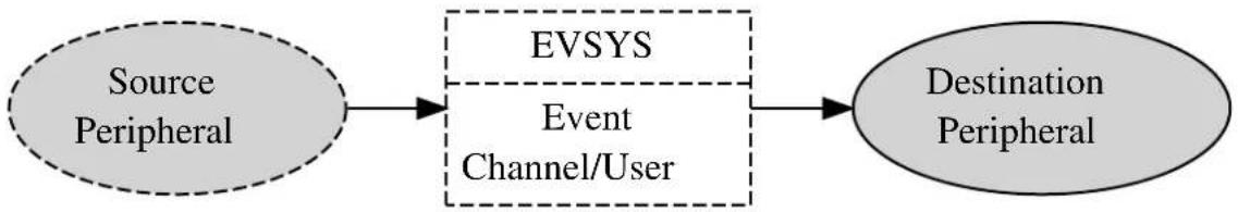
flowchart
graph LR
    A["Source Peripheral"] --> B["EVSYS"]
    B --> C["Destination Peripheral"]
    B --> D["Event Channel/User"]
Note
Identically shaped borders in the diagram indicate a shared generic clock channel.
6.2.4.3 Re-synchronous Paths
Re-synchronous event paths are a special form of synchronous events, where when edge detection or interrupts from the event channel are required, but the event generator and the event channel use different Generic Clock channels. The re-synchronous path allows the Event System to synchronize the incoming event signal from the Event Generator to the clock of the Event System module to avoid missed events, at the cost of a higher latency due to the re-synchronization process. The re-synchronous event chain is shown in Figure 6-4: Re-synchronous Paths on page 133.
Not all peripherals support Re-synchronous event paths; refer to the device datasheet.
Figure 6-4. Re-synchronous Paths

flowchart
graph LR
    A["Source Peripheral"] --> B["EVSYS"]
    B --> C["Event Channel/User"]
    C --> D["Destination Peripheral"]
Note
Identically shaped borders in the diagram indicate a shared generic clock channel.
6.2.5 Physical Connection
Figure 6-5: Physical Connection on page 134 shows how this module is interconnected within the device.
Figure 6-5. Physical Connection

flowchart
graph LR
    A["Source Periphe ra ls"] -->|Source MUXs| B["EVSYS"]
    B -->|Channel 1 MUXs Destination| C["EVSYS"]
    C --> D["Peripher crals"]
    B --> E["Event Channels"]
    C --> F["Event Users"]
6.2.6 Configuring Events
For SAM D20/D21 devices, several steps are required to properly configure an event chain, so that hardware peripherals can respond to events generated by each other, listed below.
6.2.6.1 Source Peripheral
- The source peripheral (that will generate events) must be configured and enabled.
- The source peripheral (that will generate events) must have an output event enabled.
6.2.6.2 Event System
- An event system channel must be allocated and configured with the correct source peripheral selected as the channel's event generator.
- The event system user must be configured and enabled, and attached to # event channel previously allocated.
6.2.6.3 Destination Peripheral
- The destination peripheral (that will receive events) must be configured and enabled.
- The destination peripheral (that will receive events) must have an input event enabled.
6.3 Special Considerations
There are no special considerations for this module.
6.4 Extra Information
For extra information see Extra Information for EVENTS Driver. This includes:
- Acronyms
- Dependencies
- Errata
- Module History
6.5 Examples
For a list of examples related to this driver, see Examples for EVENTS Driver.
6.6 API Overview
6.6.1 Variable and Type Definitions
6.6.1.1 Type events\_interrupt\_hook
typedef void(* events_interrupt_hook ) (struct events_resource *resource)
6.6.2 Structure Definitions
6.6.2.1 Struct events\_config
This events configuration struct is used to configure each of the channels
Table 6-1. Members
| Type Name Description | ||
| uint8_t clock_source Clock source for the event channel | ||
| enum events_edge_detect edge_detect Select edge detection mode | ||
| uint8_t generator Set event generator for the channel | ||
| enum events_path_selection path Select events channel path |
6.6.2.2 Struct events\_hook
Table 6-2. Members
| Type Name Description | ||
| events_interrupt_hook hook_func | ||
| struct events_hook * next | ||
| struct events_resource * resource |
6.6.2.3 Struct events\_resource
Event resource structure.
Note
The fields in this structure should not be altered by the user application; they are reserved for driver internals only.
6.6.3 Macro Definitions
6.6.3.1 Macro EVSYS\_ID\_GEN\_NONE
#define EVSYS_ID_GEN_NONE 0
Use this to disable any peripheral event input to a channel. This can be useful if you only want to use a channel for software generated events. Definition for no generator selection
6.6.3.2 Macro EVSYS\_ID\_USER\_NONE
#define EVSYS_ID_USER_NONE 0
Definition for no user selection
6.6.4 Function Definitions
6.6.4.1 Function events\_ack\_interrupt()
Acknowledge an interrupt source.
enum status_code events_ack_interrupt( struct events_resource * resource, enum events_interrupt_source source)
Acknowledge an interrupt source so the interrupt state is cleared in hardware
Table 6-3. Parameters
| Data direction Parameter name Description | |
| [in] resource Pointer to an events_resource | struct instance |
| [in] source One of the members in the | events_interrupt_sourceenumerator |
Returns
Status of the interrupt source
Table 6-4. Return Values
| Return value Description | |
| STATUS_OK Interrupt source was acknowledged successfully | |
6.6.4.2 Function events\_add\_hook()
Insert hook into the event drivers interrupt hook queue.
enum status_code events_add_hook(
    struct events_resource * resource,
    struct events_hook * hook)
Inserts a hook into the event drivers interrupt hook queue
Table 6-5. Parameters
| Data direction Parameter name Description | |
| [in] resource Pointer to an events_resource | struct instance |
| [in] hook Pointer to an events_hook struct | instance |
Returns
Status of the insertion procedure
Table 6-6. Return Values
| Return value Description | |
| STATUS_OK Insertion of hook went successful |
6.6.4.3 Function events\_allocate()
Allocate an event channel and set configuration.
enum status_code events_allocate(
struct events_resource * resource,
struct events_config * config)
Allocates an event channel from the event channel pool and sets the channel configuration.
Table 6-7. Parameters
| Data direction Parameter name Description | |
| [out] resource Pointer to a events_resource struct | instance |
| [in] config Pointer to a events_config struct |
Returns
Status of the configuration procedure
Table 6-8. Return Values
| Return value Description |
| STATUS_OK Allocation and configuration went successful |
| STATUS_ERR_NOT_FOUND No free event channel found |
6.6.4.4 Function events\_attach\_user()
Attach user to the event channel.
enum status_code events_attach_user(
    struct events_resource * resource,
    uint8_t user_id)
Attach a user peripheral to the event channel to receive events.
Table 6-9. Parameters
| Data direction Parameter name Description | |
| [in] resource Pointer to an events_resource | struct instance |
| [in] user_id A number identifying the user | peripheral found in the device header file. |
Returns
Status of the user attach procedure
Table 6-10. Return Values
| Return value Description | |
| STATUS_OK No errors detected when attaching the event user | |
6.6.4.5 Function events\_create\_hook()
Initializes a interrupt hook for insertion in the event interrupt hook queue.
enum status_code events_create_hook(
struct events_hook * hook,
events_interrupt_hook hook_func)
Initializes a hook structure so it is ready for insertion in the interrupt hook queue
Table 6-11. Parameters
| Data direction Parameter name Description | |
| [out] hook Pointer to an events_hook struct | instance |
| [in] hook_func Pointer to a function containing the | interrupt hook code |
Returns
Status of the hook creation procedure
Table 6-12. Return Values
| Return value Description | |
| STATUS_OK Creation and initialization of interrupt hook | went successful |
6.6.4.6 Function events\_del\_hook()
Remove hook from the event drivers interrupt hook queue.
enum status_code events_del_hook(
    struct events_resource * resource,
    struct events_hook * hook)
Removes a hook from the event drivers interrupt hook queue
Table 6-13. Parameters
| Data direction Parameter name Description | |
| [in] resource Pointer to an events_resource | struct instance |
| [in] hook Pointer to an events_hook struct | instance |
Returns
Status of the removal procedure
Table 6-14. Return Values
| Return value Description | |
| STATUS_OK Removal of hook went successful | |
| STATUS_ERR_NO_MEMORY There is no hooks instances in the event driver interrupt hook list | |
| STATUS_ERR_NOT_FOUND Interrupt hook not found in the event drivers interrupt hook list | |
6.6.4.7 Function events\_detach\_user()
Detach an user peripheral from the event channel.
enum status_code events_detach_user(
    struct events_resource * resource,
    uint8_t user_id)
Deattach an user peripheral from the event channels so it does not receive any more events.
Table 6-15. Parameters
| Data direction Parameter name Description | |
| [in] resource Pointer to an event_resource struct | instance |
| [in] user_id A number identifying the user | peripheral found in the device header file. |
Returns
Status of the user detach procedure
Table 6-16. Return Values
| Return value Description | |
| STATUS_OK No errors detected when detaching the event user | |
6.6.4.8 Function events\_disable\_interrupt\_source()
Disable interrupt source.
enum status_code events_disable_interrupt_source(
    struct events_resource * resource,
    enum events_interrupt_source source)
Disable an interrupt source so can trigger execution of an interrupt hook
Table 6-17. Parameters
| Data direction Parameter name Description | |
| [in] resource Pointer to an events_resource | struct instance |
| [in] source One of the members in the | events_interrupt_source enumerator |
Returns
Status of the interrupt source enable procedure
Table 6-18. Return Values
| Return value Description | |
| STATUS_OK Enabling of the interrupt source went successful | |
| STATUS_ERR_INVALID_ARG Interrupt source does not exist | |
6.6.4.9 Function events\_enable\_interrupt\_source()
Enable interrupt source.
enum status_code events_enable_interrupt_source(
    struct events_resource * resource,
    enum events_interrupt_source source)
Enable an interrupt source so can trigger execution of an interrupt hook
Table 6-19. Parameters
| Data direction Parameter name Description | |
| [in] resource Pointer to an events_resource | struct instance |
| [in] source One of the members in the | events_interrupt_source enumerator |
Returns
Status of the interrupt source enable procedure
Table 6-20. Return Values
| Return value Description | |
| STATUS_OK Enabling of the interrupt source went successful | |
| STATUS_ERR_INVALID_ARG Interrupt source does not exist | |
6.6.4.10 Function events\_get\_config\_defaults()
Initializes an event configurations struct to defaults.
void events_get_config_defaults(struct events_config * config)
Initailizes an event configuration struct to predefined safe default settings.
Table 6-21. Parameters
| Data direction Parameter name Description | |
| [in] config Pointer to an instance of struct | events_config |
6.6.4.11 Function events\_get\_free\_channels()
Get number of free channels.
uint8_t events_get_free_channels(void)
Get number of allocatable channels in the events system resource pool
Returns
The number of free channels in the event system
6.6.4.12 Function events_is_busy()
Check if a channel is busy.
bool events_is_busy(
    struct events_resource * resource)
Check if a channel is busy, a channels stays busy until all users connected to the channel has handled an event
Table 6-22. Parameters
| Data direction Parameter name Description | |
| [in] resource Pointer to a events_resource struct | instance |
Returns
Status of the channels busy state
Table 6-23. Return Values
| Return value Description | |
| true One or more users connected to the channel has not handled the last event | |
| false All users are ready handle new events | |
6.6.4.13 Function events_is_detected()
Check if event is detected on event channel.
bool events_is_detected(
    struct events_resource * resource)
Check if an event has been detected on the channel
Note
This function will clear the event detected interrupt flag
Table 6-24. Parameters
| Data direction Parameter name Description | |
| [in] resource Pointer to an events_resource | struct |
Returns
Status of the event detection interrupt flag
Table 6-25. Return Values
| Return value Description | |
| true Event has been detected | |
| false Event has not been detected |
6.6.4.14 Function events\_is\_interrupt\_set()
Check if interrupt source is set.
bool events_is_interrupt_set(
    struct events_resource * resource,
    enum events_interrupt_source source)
Check if an interrupt source is set and should be processed
Table 6-26. Parameters
| Data direction Parameter name Description | |
| [in] resource Pointer to an events_resource | struct instance |
| [in] source One of the memebers in the | events_interrupt_source enumerator |
Returns
Status of the interrupt source
Table 6-27. Return Values
| Return value Description | |
| true Interrupt source is set | |
| false Interrupt source is not set |
6.6.4.15 Function events\_is\_overrun()
Check if there has been an overrun situation on this channel.
bool events_is_overrun(
    struct events_resource * resource)
Check if there has been an overrun situation on this channel
Note
This function will clear the event overrun detected interrupt flag
Table 6-28. Parameters
| Data direction Parameter name Description | |
| [in] resource Pointer to an events_resource | struct |
Returns
Status of the event overrun interrupt flag
Table 6-29. Return Values
| Return value Description | |
| true Event overrun has been detected | |
| false Event overrun has not been detected |
6.6.4.16 Function events_is_users_ready()
Check if all users connected to the channel is ready.
bool events_is_users_ready(
    struct events_resource * resource)
Check if all users connected to the channel is ready to handle incoming events
Table 6-30. Parameters
| Data direction Parameter name Description | |
| [in] resource Pointer to an events_resource | struct |
Returns
The ready status of users connected to an event channel
Table 6-31. Return Values
| Return value Description | |
| true All users connect to event channel is ready handle | incoming events |
| false One or more users connect to event channel is not | ready to handle incoming events |
6.6.4.17 Function events_release()
Release allocated channel back the resource pool.
enum status_code events_release(
    struct events_resource * resource)
Release an allocated channel back to the resource pool to make it available for other purposes.
Table 6-32. Parameters
| Data direction Parameter name Description | |
| [in] resource Pointer to an events_resource | struct |
Returns
Status of channel release procedure
Table 6-33. Return Values
| Return value Description | |
| STATUS_OK No error was detected when channel was released | |
| STATUS_BUSY One or more event users have not processed the last event | |
| STATUS_ERR_NOT_INITIALIZED Channel not allocated, and can derfor not be released | |
6.6.4.18 Function events\_trigger()
Trigger software event.
enum status_code events_trigger(
    struct events_resource * resource)
Trigger an event by software
Table 6-34. Parameters
| Data direction Parameter name Description | |
| [in] resource Pointer to an events_resource | struct |
Returns
Status of the event software procedure
Table 6-35. Return Values
| Return value Description | |
| STATUS_OK No error was detected when software tigger signal was issued | |
| STATUS_ERR_UNSUPPORTED_DEV If the channel path is asynchronous and/or the edge detection is not set to RISING | |
6.6.5 Enumeration Definitions
6.6.5.1 Enum events\_edge\_detect
Event channel edge detect setting
Table 6-36. Members
| Enum value Description | |
| EVENTS_EDGE_DETECT_NONE No event output | |
| EVENTS_EDGE_DETECT_RISING Event on rising edge | |
| EVENTS_EDGE_DETECT_FALLING Event on falling edge | |
| EVENTS_EDGE_DETECT_BOTH | Event on both edges |
6.6.5.2 Enum events\_interrupt\_source
Interrupt source selector definitions
Table 6-37. Members
| Enum value Description | |
| EVENTS_INTERRUPT_OVERRUN | |
| EVENTS_INTERRUPT_DETECT |
6.6.5.3 Enum events\_path\_selection
Event channel path selection
Table 6-38. Members
| Enum value Description | |
| EVENTS_PATH_SYNCHRONOUS Select the synchronous path for this event channel | |
| EVENTS_PATH_RESYNCHRONIZED Select the resynchronizer path for this event channel | |
| EVENTS_PATH_ASYNCHRONOUS Select the asynchronous path for this event channel | |
6.7 Extra Information for EVENTS Driver
6.7.1 Acronyms
Below is a table listing the acronyms used in this module, along with their intended meanings.
| Acronym Description | |
| CPU Central Processing Unit | |
| MUX Multiplexer |
6.7.2 Dependencies
This driver has the following dependencies:
- System Clock Driver
6.7.3 Errata
There are no errata related to this driver.
6.7.4 Module History
An overview of the module history is presented in the table below, with details on the enhancements and fixes made to the module since its first release. The current version of this corresponds to the newest version in the table.
| Changelog |
| Rewrite of events driver. |
| Initial Release |
6.8 Examples for EVENTS Driver
This is a list of the available Quick Start guides (QSGs) and example applications for SAM D20/D21 Event System Driver (EVENTS). QSGs are simple examples with step-by-step instructions to configure and use this driver in a selection of use cases. Note that QSGs can be compiled as a standalone application or be added to the user application.
- Quick Start Guide for EVENTS - Basic
- Quick Start Guide for EVENTS - interrupt hooks
6.8.1 Quick Start Guide for EVENTS - Basic
In this use case, the EVENT module is configured for:
- Synchronous event path with rising edge detection on the input
• One user attached to the configured event channel - No hardware event generator attached to the channel
This use case allocates an event channel, this channel is not connected to any hardware event generator, events are software triggered. One user is connected to the allocated and configured event channel.
6.8.1.1 Setup
Prerequisites
There are no special setup requirements for this use-case.
Code
Copy-paste the following setup code to your user application:
#define EXAMPLE_EVENT_GENERATOR    EVSYS_ID_GEN_TC4_MCX_0
#define EXAMPLE_EVENT_USER    EVSYS_ID_USER_TC3_EVU

static void configure_event_channel(struct events_resource *resource)
{
    struct events_config config;

    events_get_config_defaults(&config);

    config.generator    = EXAMPLE_EVENT_GENERATOR;
    config.edge_detect    = EVENTS_EDGE_DETECT_RISING;
    config.path    = EVENTS_PATH_SYNCHRONOUS;
    config.clock_source    = GCLK_GENERATOR_0;

    events_allocate(resource, &config);
}

static void configure_event_user(struct events_resource *resource)
{
    events_attach_user(resource, EXAMPLE_EVENT_USER);
}
Create an event resource struct and add to user application (typically the start of main()):
struct events_resource example_event;
Add to user application initialization (typically the start of main()):
configure_event_channel(&example_event);
configure_event_user(&example_event);
Workflow
- Create an event channel configuration struct, which can be filled out to adjust the configuration of a single event channel.
struct events_config config;
- Initialize the event channel configuration struct with the module's default values.
events_get_config_defaults(&config);
Note
This should always be performed before using the configuration struct to ensure that all values are initialized to known default settings.
- Adjust the configuration struct to request that the channel be attached to the specified event generator, that rising edges of the event signal be detected on the channel and that the synchronous event path be used.
config.generator = EXAMPLE_EVENT_GENERATOR;
config.edge_detect = EVENTS_EDGE_DETECT_RISING;
config.path = EVENTS_PATH_SYNCHRONOUS;
config.clock_source = GCLK_GENERATOR_0;
- Allocate and configure the channel using the configuration structure.
events_allocate(resource, &config);
Note
The existing configuration struct may be re-used, as long as any values that have been altered from the default settings are taken into account by the user application.
- Attach an user to the channel
events_attach_user(resource, EXAMPLE_EVENT_USER);
6.8.1.2 Use Case
Code
Copy-paste the following code to your user application:
while (events_is_busy(&example_event)) {
    /* Wait for channel */
};
events_trigger(&example_event);
while (true) {
    /* Nothing to do */
}
Workflow
- Wait for the even channel to become ready to accept a new event trigger.
while (events_is_busy(&example_event)) {
    /* Wait for channel */
};
- Perform a software event trigger on the configured event channel.
events_trigger(&example_event);
6.8.2 Quick Start Guide for EVENTS - interrupt hooks
In this use case, the EVENT module is configured for:
- Synchronous event path with rising edge detection
• TC4 as event generator on the allocated event channel - No event channel user attached
- An event interrupt hook is used to execute some code when an event is detected
In this usecase TC4 is used as event generator, generating events on overflow. No user attached, counting events on the channel. To able to execute some code when an event is detected, an interrupt hook is used. The interrupt hook will also count the number of events detected and toggle a led on the board each time an event is detected.
Note
Because this example is showing how to setup an interrupt hook there is no user attached to the user.
6.8.2.1 Setup
Prerequisites
There are no special setup requirements for this use-case.
Code
Copy-paste the following setup code to your user application:
#define EXAMPLE_EVENT_GENERATOR    EVSYS_ID_GEN_TC4_OVF
#define EXAMPLE_EVENT_USER    EVSYS_ID_USER_NONE

#define TC_MODULE TC4

static volatile uint32_t event_count = 0;

void event_counter(struct events_resource *resource);

static void configure_event_channel(struct events_resource *resource)
{
    struct events_config config;

    events_get_config_defaults(&config);

    config.generator    = EXAMPLE_EVENT_GENERATOR;
    config.edge_detect    = EVENTS_EDGE_DETECT_RISING;
    config.path    = EVENTS_PATH_SYNCHRONOUS;
    config.clock_source    = GCLK_GENERATOR_0;

    events_allocate(resource, &config);
}

static void configure_event_user(struct events_resource *resource)
{
    events_attach_user(resource, EXAMPLE_EVENT_USER);
}
static void configure_tc(struct tc_module *tc_instance)
{
    struct tc_config config_tc;
    struct tc_events config_events;

    tc_get_config_defaults(&config_tc);

    config_tc.counter_size = TC_COUNTER_SIZE_8BIT;
    config_tc.wave_generation = TC_WAVE_GENERATION_NORMAL_FREQ;
    config_tc.clock_source = GCLK_GENERATOR_1;
    config_tc.clock_prescaler = TC_CLOCK_PRESCALER_DIV64;

    tc_init(tc_instance, TC_MODULE, &config_tc);

    config_events.generate_event_on_overflow = true;
    tc_enable_events(tc_instance, &config_events);

    tc_enable(tc_instance);
}

static void configure_event_interrupt(struct events_resource *resource, struct events_hook *hook)
{
    events_create_hook(hook, event_counter);

    events_add_hook(resource, hook);
    events_enable_interrupt_source(resource, EVENTS_INTERRUPT_DETECT);
}

void event_counter(struct events_resource *resource)
{
    if (events_is_interrupt_set(resource, EVENTS_INTERRUPT_DETECT)) {
    port_pin_toggle_output_level(LED_0_PIN);

    event_count++;
    events_ack_interrupt(resource, EVENTS_INTERRUPT_DETECT);
    }
}
Add to user application initialization (typically the start of main()):
struct tc_module tc_instance;
struct events_resource example_event;
struct events_hook hook;

system_init();
system_interrupt_enable_global();

configure_event_channel(&example_event);
configure_event_user(&example_event);
configure_event_interrupt(&example_event, &hook);
configure_tc(&tc_instance);
Workflow
- Create an event channel configuration structure instance which will contain the configuration for the event.
struct events_config config;
- Initialize the event channel configuration struct with safe default values.
Note
This shall always be performed before using the configuration struct to ensure that all members are initialized to known default values.
events_get_config_defaults(&config);
-
Adjust the configuration structure
-
Use EXAMPLE_EVENT_GENERATOR as event generator
• Detect events on rising edge
• Use the synchronous event path - Use GCLK Generator 0 as event channel clock source
config.generator = EXAMPLE_EVENT_GENERATOR;
config.edge_detect = EVENTS_EDGE_DETECT_RISING;
config.path = EVENTS_PATH_SYNCHRONOUS;
config.clock_source = GCLK_GENERATOR_0;
- Allocate and configure the channel using the configuration structure.
events_allocate(resource, &config);
- Make sure there is no user attached. To attach an user, change the value of EXAMPLE_EVENT_USER to the correct peripheral ID.
events_attach_user(resource, EXAMPLE_EVENT_USER);
- Create config_tc and config_events configuration structure instances.
struct tc_config config_tc;
struct tc_events config_events;
- Initialize the TC module configuration structure with safe default values.
Note
This function shall always be called on new configuration structure instances to make sure that all structure members is initialized.
tc_get_config_defaults(&config_tc);
-
Adjust the config_tc structure
-
Set counter size to 8bit
-
Set wave generation mode to normal frequency generation
-
Use GCLK generator 1 to as tc module clock source
• Prescale the input clock with 64
config_tc.counter_size = TC_COUNTER_SIZE_8BIT;
config_tc.wave_generation = TC_WAVE_GENERATION_NORMAL_FREQ;
config_tc.clock_source = GCLK_GENERATOR_1;
config_tc.clock_prescaler = TC_CLOCK_PRESCALER_DIV64;
- Initialize, configure and associate the tc_instance handle with the TC hardware pointed to by TC_MODULE
tc_init(tc_instance, TC_MODULE, &config_tc);
- Adjust the config_events structure to enable event generation on overflow in the timer and then enable the event configuration
config_events.generate_event_on_overflow = true;
tc_enable_events(tc_instance, &config_events);
- Enable the timer/counter module
tc_enable(tc_instance);
- Create a new interrupt hook and use the function event_counter as hook code
events_create_hook(hook, event_counter);
- Add the newly created hook to the interrupt hook queue and enable the event detected interrupt
events_add_hook(resource, hook);
events_enable_interrupt_source(resource, EVENTS_INTERRUPT_DETECT);
- Example interrupt hook code. If the hook was triggered by a event detected interrupt on the event channel this code will toggle the led on the Xplained PRO board and increase the value of the event_count variable. The interrupt then acknowledged.
void event_counter(struct events_resource *resource)
{
    if (events_is_interrupt_set(resource, EVENTS_INTERRUPT_DETECT)) {
    port_pin_toggle_output_level(LED_0_PIN);
    event_count++;
    events_ack_interrupt(resource, EVENTS_INTERRUPT_DETECT);
    }
}
6.8.2.2 Use Case
Code
Copy-paste the following code to your user application:
while (events_is_busy(&example_event)) {
/* Wait for channel */
};
tc_start_counter(&tc_instance);
while (true) {
    /* Nothing to do */
}
Workflow
- Wait for the even channel to become ready.
while (events_is_busy(&example_event)) {
    /* Wait for channel */
};
- Start the timer/counter
tc_start_counter(&tc_instance);
7. SAM D20/D21 External Interrupt Driver (EXTINT)
This driver for SAM D20/D21 devices provides an interface for the configuration and management of external interrupts generated by the physical device pins, including edge detection. The following driver API modes are covered by this manual:
- Polled APIs
- Callback APIs
The following peripherals are used by this module:
• EIC (External Interrupt Controller)
The outline of this documentation is as follows:
- Prerequisites
- Module Overview
• Special Considerations - Extra Information
- Examples
- API Overview
7.1 Prerequisites
There are no prerequisites for this module.
7.2 Module Overview
The External Interrupt (EXTINT) module provides a method of asynchronously detecting rising edge, falling edge or specific level detection on individual I/O pins of a device. This detection can then be used to trigger a software interrupt or event, or polled for later use if required. External interrupts can also optionally be used to automatically wake up the device from sleep mode, allowing the device to conserve power while still being able to react to an external stimulus in a timely manner.
7.2.1 Logical Channels
The External Interrupt module contains a number of logical channels, each of which is capable of being individually configured for a given pin routing, detection mode and filtering/wake up characteristics.
Each individual logical external interrupt channel may be routed to a single physical device I/O pin in order to detect a particular edge or level of the incoming signal.
7.2.2 NMI Channels
One or more Non Maskable Interrupt (NMI) channels are provided within each physical External Interrupt Controller module, allowing a single physical pin of the device to fire a single NMI interrupt in response to a particular edge or level stimulus. A NMI cannot, as the name suggests, be disabled in firmware and will take precedence over any in-progress interrupt sources.
NMIs can be used to implement critical device features such as forced software reset or other functionality where the action should be executed in preference to all other running code with a minimum amount of latency.
7.2.3 Input Filtering and Detection
To reduce the possibility of noise or other transient signals causing unwanted device wake-ups, interrupts and/or events via an external interrupt channel, a hardware signal filter can be enabled on individual channels. This filter provides a Majority-of-Three voter filter on the incoming signal, so that the input state is considered to be the
majority vote of three subsequent samples of the pin input buffer. The possible sampled input and resulting filtered output when the filter is enabled is shown in Table 7-1: Sampled input and resulting filtered output on page 154.
Table 7-1. Sampled input and resulting filtered output
| Input Sample 1 Input Sample 2 Input Sample 3 Filtered Output | |||
| 0 0 0 0 | |||
| 0 0 1 0 | |||
| 0 1 0 0 | |||
| 0 1 1 1 | |||
| 1 0 0 0 | |||
| 1 0 1 1 | |||
| 1 1 0 1 | |||
| 1 1 1 1 | |||
7.2.4 Events and Interrupts
Channel detection states may be polled inside the application for synchronous detection, or events and interrupts may be used for asynchronous behavior. Each channel can be configured to give an asynchronous hardware event (which may in turn trigger actions in other hardware modules) or an asynchronous software interrupt.
Note
The connection of events between modules requires the use of the SAM D20/D21 Event System Driver (EVENTS) to route output event of one module to the input event of another. For more information on event routing, refer to the event driver documentation.
7.2.5 Physical Connection
Figure 7-1: Physical Connection on page 154 shows how this module is interconnected within the device.
Figure 7-1. Physical Connection

flowchart
graph TD
    A["Port Pad"] --> B["Peripheral Mux"]
    B --> C["EIC Module Other Peripheral Modules"]
    B --> D["Peripheral Modules"]
7.3 Special Considerations
Not all devices support disabling of the NMI channel(s) detection mode - see your device datasheet.
7.4 Extra Information
For extra information see Extra Information for EXTINT Driver. This includes:
• Acronyms
- Dependencies
- Errata
- Module History
7.5 Examples
For a list of examples related to this driver, see Examples for EXTINT Driver.
7.6 API Overview
7.6.1 Variable and Type Definitions
7.6.1.1 Callback configuration and initialization
Type extint_callback_t
typedef void(* extint_callback_t )(void)
Type definition for an EXTINT module callback function.
7.6.2 Structure Definitions
7.6.2.1 Struct extint\_chan\_conf
Configuration structure for the edge detection mode of an external interrupt channel.
Table 7-2. Members
| Type Name Description | ||
| enum extint_detect detection_criteria Edge detection mode to use. | ||
| bool filter_input_signal Filter the raw input signal to | prevent noise from triggering an interrupt accidentally, using a 3 sample majority filter. | |
| uint32_t gpio_pin GPIO pin the NMI should be | connected to. | |
| uint32_t gpio_pin_mux MUX position the GPIO pin should | be configured to. | |
| enum extint_pull gpio_pin_pull Internal pull to enable on the input | pin. | |
| bool | wake_if_sleeping | Wake up the device if the channel interrupt fires during sleep mode. |
7.6.2.2 Struct extint\_events
Event flags for the extint_enable_events() and extint_disable_events().
Table 7-3. Members
| Type Name Description | ||
| bool generate_event_on_detect[] If true, an event will be generated | when an external interrupt channel detection state changes. | |
7.6.2.3 Struct extint\_nmi\_conf
Configuration structure for the edge detection mode of an external interrupt NMI channel.
Table 7-4. Members
| Type Name Description | ||
| enum extint_detect detection_criteria | Edge detection mode to use. Not | all devices support all possible detection modes for NMIs. |
| bool filter_input_signal Filter the raw input signal to | prevent noise from triggering an interrupt accidentally, using a 3 sample majority filter. | |
| uint32_t gpio_pin GPIO pin the NMI should be | connected to. | |
| uint32_t gpio_pin_mux MUX position the GPIO pin should | be configured to. | |
| enum extint_pull gpio_pin_pull Internal pull to enable on the input | pin. | |
7.6.3 Macro Definitions
7.6.3.1 Macro EXTINT\_CLOCK\_SOURCE
#define EXTINT_CLOCK_SOURCE GCLK_GENERATOR_0
Configuration option, setting the EIC clock source which can be used for EIC edge detection or filtering. This option may be overridden in the module configuration header file conf_extint.h.
7.6.4 Function Definitions
7.6.4.1 Configuration and initialization
Function extint\_is\_syncing()
Determines if the hardware module(s) are currently synchronizing to the bus.
bool extint_is_syncing(void)
Checks to see if the underlying hardware peripheral module(s) are currently synchronizing across multiple clock domains to the hardware bus, This function can be used to delay further operations on a module until such time that it is ready, to prevent blocking delays for synchronization in the user application.
Returns
Synchronization status of the underlying hardware module(s).
Table 7-5. Return Values
| Return value Description | |
| true If the module has completed synchronization | |
| false If the module synchronization is ongoing |
7.6.4.2 Event management
Function extint\_enable\_events()
Enables an External Interrupt event output.
void extint_enable_events(
    struct extint_events *const events)
Enables one or more output events from the External Interrupt module. See here for a list of events this module supports.
Note
Events cannot be altered while the module is enabled.
Table 7-6. Parameters
| Data direction Parameter name Description | |
| [in] events Struct containing flags of events to | enable |
Function extint\_disable\_events()
Disables an External Interrupt event output.
void extint_disable_events(
    struct extint_events *const events)
Disables one or more output events from the External Interrupt module. See here for a list of events this module supports.
Note
Events cannot be altered while the module is enabled.
Table 7-7. Parameters
| Data direction Parameter name Description | |
| [in] events Struct containing flags of events to | disable |
7.6.4.3 Configuration and initialization (channel)
Function extint\_chan\_get\_config\_defaults()
Initializes an External Interrupt channel configuration structure to defaults.
void extint_chan_get_config_defaults(
    struct extint_chan_conf *const config)
Initializes a given External Interrupt channel configuration structure to a set of known default values. This function should be called on all new instances of these configuration structures before being modified by the user application.
The default configuration is as follows:
- Wake the device if an edge detection occurs whilst in sleep
- Input filtering disabled
- Internal pull-up enabled
• Detect falling edges of a signal
Table 7-8. Parameters
| Data direction Parameter name Description | |
| [out] config Configuration structure to initialize | to default values |
Function extint\_chan\_set\_config()
Writes an External Interrupt channel configuration to the hardware module.
void extint_chan_set_config(
    const uint8_t channel,
    const struct extint_chan_conf *const config)
Writes out a given configuration of an External Interrupt channel configuration to the hardware module. If the channel is already configured, the new configuration will replace the existing one.
Table 7-9. Parameters
| Data direction Parameter name Description | |
| [in] channel External Interrupt channel to | configure |
| [in] config Configuration settings for the | channel |
7.6.4.4 Configuration and initialization (NMI)
Function extint\_nmi\_get\_config\_defaults()
Initializes an External Interrupt NMI channel configuration structure to defaults.
void extint_nmi_get_config_defaults(
struct extint_nmi_conf *const config)
Initializes a given External Interrupt NMI channel configuration structure to a set of known default values. This function should be called on all new instances of these configuration structures before being modified by the user application.
The default configuration is as follows:
- Input filtering disabled
• Detect falling edges of a signal
Table 7-10. Parameters
| Data direction Parameter name Description | |
| [out] config Configuration structure to initialize | to default values |
Function extint\_nmi\_set\_config()
Writes an External Interrupt NMI channel configuration to the hardware module.
enum status_code extint_nmi_set_config(
    const uint8_t nmi_channel,
    const struct extint_nmi_conf *const config)
Writes out a given configuration of an External Interrupt NMI channel configuration to the hardware module. If the channel is already configured, the new configuration will replace the existing one.
Table 7-11. Parameters
| Data direction Parameter name Description | |
| [in] nmi_channel External Interrupt NMI channel to | configure |
| [in] config Configuration settings for the | channel |
Returns
Status code indicating the success or failure of the request.
Table 7-12. Return Values
| Return value Description | |
| STATUS_OK Configuration succeeded | |
| STATUS_ERR_PIN_MUX_INVALID An invalid pin mux value was supplied | |
| STATUS_ERR_BAD_FORMAT An invalid detection mode was requested |
7.6.4.5 Detection testing and clearing (channel)
Function extint\_chan\_is\_detected()
Retrieves the edge detection state of a configured channel.
bool extint_chan_is_detected(
const uint8_t channel)
Reads the current state of a configured channel, and determines if the detection criteria of the channel has been met.
Table 7-13. Parameters
| Data direction Parameter name Description | |
| [in] channel External Interrupt channel index to | check. |
Returns
Status of the requested channel's edge detection state.
Table 7-14. Return Values
| Return value Description | |
| true If the channel's edge/level detection criteria was met | |
| false If the channel has not detected its configured criteria |
Function extint\_chan\_clear\_detected()
Clears the edge detection state of a configured channel.
void extint_chan_clear_detected(const uint8_t channel)
Clears the current state of a configured channel, readying it for the next level or edge detection.
Table 7-15. Parameters
| Data direction Parameter name Description | |
| [in] channel External Interrupt channel index to | check. |
7.6.4.6 Detection testing and clearing (NMI)
Function extint\_nmi\_is\_detected()
Retrieves the edge detection state of a configured NMI channel.
bool extint_nmi_is_detected(const uint8_t nmi_channel)
Reads the current state of a configured NMI channel, and determines if the detection criteria of the NMI channel has been met.
Table 7-16. Parameters
| Data direction Parameter name Description | |
| [in] nmi_channel External Interrupt NMI channel | index to check. |
Returns
Status of the requested NMI channel's edge detection state.
Table 7-17. Return Values
| Return value Description | |
| true If the NMI channel's edge/level detection criteria was | met |
| false If the NMI channel has not detected its configured | criteria |
Function extint\_nmi\_clear\_detected()
Clears the edge detection state of a configured NMI channel.
void extint_nmi_clear_detected( const uint8_t nmi_channel)
Clears the current state of a configured NMI channel, readying it for the next level or edge detection.
Table 7-18. Parameters
| Data direction Parameter name Description | |
| [in] nmi_channel External Interrupt NMI channel | index to check. |
7.6.4.7 Callback configuration and initialization
Function extint\_register\_callback()
Registers an asynchronous callback function with the driver.
enum status_code extint_register_callback(
    const extint_callback_t callback,
    const uint8_t channel,
    const enum extint_callback_type type)
Registers an asynchronous callback with the EXTINT driver, fired when a channel detects the configured channel detection criteria (e.g. edge or level). Callbacks are fired once for each detected channel.
Note
NMI channel callbacks cannot be registered via this function; the device's NMI interrupt should be hooked directly in the user application and the NMI flags manually cleared via extint_nmi_clear_detected().
Table 7-19. Parameters
| Data direction Parameter name Description | |
| [in] callback Pointer to the callback function to | register |
| [in] channel Logical channel to register callback | for |
Data direction Parameter name Description
[in] type Type of callback function to register
Returns
Status of the registration operation.
Table 7-20. Return Values
| Return value Description | |
| STATUS_OK The callback was registered successfully. | |
| STATUS_ERR_INVALID_ARG If an invalid callback type was supplied. | |
| STATUS_ERR_ALREADY_INITIALIZED Callback function has been registered, need unregister first. |
Function extint\_unregister\_callback()
Unregisters an asynchronous callback function with the driver.
enum status_code extint_unregister_callback(
    const extint_callback_t callback,
    const uint8_t channel,
    const enum extint_callback_type type)
Unregisters an asynchronous callback with the EXTINT driver, removing it from the internal callback registration table.
Table 7-21. Parameters
| Data direction Parameter name Description | |
| [in] callback Pointer to the callback function to | unregister |
| [in] channel Logical channel to unregister | callback for |
| [in] type Type of callback function to | unregister |
Returns
Status of the de-registration operation.
Table 7-22. Return Values
| Return value Description | |
| STATUS_OK The callback was Unregistered successfully. | |
| STATUS_ERR_INVALID_ARG If an invalid callback type was supplied. | |
| STATUS_ERR_BAD_ADDRESS No matching entry was found in the registration table. | |
Function extint\_get\_current\_channel()
Find what channel caused the callback.
uint8_t extint_get_current_channel(void)
Can be used in an EXTINT callback function to find what channel caused the callback in case same callback is used by multiple channels.
Returns
Channel number.
7.6.4.8 Callback enabling and disabling (channel)
Function extint\_chan\_enable\_callback()
Enables asynchronous callback generation for a given channel and type.
enum status_code extint_chan_enable_callback(
    const uint8_t channel,
    const enum extint_callback_type type)
Enables asynchronous callbacks for a given logical external interrupt channel and type. This must be called before an external interrupt channel will generate callback events.
Table 7-23. Parameters
| Data direction Parameter name Description | |
| [in] channel Logical channel to enable callback | generation for |
| [in] type Type of callback function callbacks | to enable |
Returns
Status of the callback enable operation.
Table 7-24. Return Values
| Return value Description | |
| STATUS_OK The callback was enabled successfully. | |
| STATUS_ERR_INVALID_ARG If an invalid callback type was supplied. | |
Function extint\_chan\_disable\_callback()
Disables asynchronous callback generation for a given channel and type.
enum status_code extint_chan_disable_callback( const uint8_t channel, const enum extint_callback_type type)
Disables asynchronous callbacks for a given logical external interrupt channel and type.
Table 7-25. Parameters
| Data direction Parameter name Description | |
| [in] channel Logical channel to disable callback | generation for |
| [in] type Type of callback function callbacks | to disable |
Returns
Status of the callback disable operation.
Table 7-26. Return Values
| Return value Description | |
| STATUS_OK The callback was disabled successfully. | |
| STATUS_ERR_INVALID_ARG If an invalid callback type was supplied. | |
7.6.5 Enumeration Definitions
7.6.5.1 Callback configuration and initialization
Enum extint\_callback\_type
Enum for the possible callback types for the EXTINT module.
Table 7-27. Members
| Enum value Description | |
| EXTINT_CALLBACK_TYPE_DETECT Callback type for when an external interrupt detects the configured channel criteria (i.e. edge or level detection) | |
7.6.5.2 Enum extint\_detect
Enum for the possible signal edge detection modes of the External Interrupt Controller module.
Table 7-28. Members
| Enum value Description | |
| EXTINT_DETECT_NONE No edge detection. Not allowed as a NMI detection mode on some devices. | |
| EXTINT_DETECT_RISING Detect rising signal edges. | |
| EXTINT_DETECT_FALLING Detect falling signal edges. | |
| EXTINT_DETECT_BOTH Detect both signal edges. | |
| EXTINT_DETECT_HIGH Detect high signal levels. | |
| EXTINT_DETECT_LOW Detect low signal levels. | |
7.6.5.3 Enum extint\_pull
Enum for the possible pin internal pull configurations.
Note
Disabling the internal pull resistor is not recommended if the driver is used in interrupt (callback) mode, due the possibility of floating inputs generating continuous interrupts.
Table 7-29. Members
| Enum value Description | |
| EXTINT_PULL_UP Internal pull-up resistor is enabled on the pin. | |
| EXTINT_PULL_DOWN Internal pull-down resistor is enabled on the pin. | |
| EXTINT_PULL_NONE Internal pull resistor is disconnected from the pin. | |
7.7 Extra Information for EXTINT Driver
7.7.1 Acronyms
The table below presents the acronyms used in this module:
| Acronym Description | |
| EIC External Interrupt Controller | |
| MUX Multiplexer | |
| NMI Non-Maskable Interrupt |
7.7.2 Dependencies
This driver has the following dependencies:
• System Pin Multiplexer Driver
7.7.3 Errata
There are no errata related to this driver.
7.7.4 Module History
An overview of the module history is presented in the table below, with details on the enhancements and fixes made to the module since its first release. The current version of this corresponds to the newest version in the table.
| Changelog |
| Driver updated to follow driver type convention.Removed extint_reset(), extint_disable() and extint_enable() functions. Added internal function_system_extint_init().Added configuration EXTINT_CLOCK_SOURCE in conf_extint.h.Removed configuration EXTINT_CALLBACKS_MAX in conf_extint.h, and added channel parameter in the register functions extint_register_callback() and extint_unregister_callback(). |
| Updated interrupt handler to clear interrupt flag before calling callback function. |
| Updated initialization function to also enable the digital interface clock to the module if it is disabled. |
| Initial Release |
7.8 Examples for EXTINT Driver
This is a list of the available Quick Start guides (QSGs) and example applications for SAM D20/D21 External Interrupt Driver (EXTINT). QSGs are simple examples with step-by-step instructions to configure and use this driver in a selection of use cases. Note that QSGs can be compiled as a standalone application or be added to the user application.
- Quick Start Guide for EXTINT - Basic
- Quick Start Guide for EXTINT - Callback
7.8.1 Quick Start Guide for EXTINT - Basic
In this use case, the EXTINT module is configured for:
- External interrupt channel connected to the board LED is used
- External interrupt channel is configured to detect both input signal edges
This use case configures a physical I/O pin of the device so that it is routed to a logical External Interrupt Controller channel to detect rising and falling edges of the incoming signal.
When the board button is pressed, the board LED will light up. When the board button is released, the LED will turn off.
7.8.1.1 Setup
Prerequisites
There are no special setup requirements for this use-case.
Code
Copy-paste the following setup code to your user application:
void configure_extint_channel(void)
{
    struct extint_chan_conf config_extint_chan;
    extint_chan_get_config_defaults(&config_extint_chan);

    config_extint_chan.GPIO_pin = BUTTON_0_EIC_PIN;
    config_extint_chan.GPIO_pin_mux = BUTTON_0_EIC_MUX;
    config_extint_chan.GPIO_pin_pull = EXTINT_PULL_UP;
    config_extint_chan.detection_criteria = EXTINT_DETECT_BOTH;
    extint_chan_set_config(BUTTON_0_EIC_LINE, &config_extint_chan);
}
Add to user application initialization (typically the start of main()):
configure_extint_channel();
Workflow
- Create an EXTINT module channel configuration struct, which can be filled out to adjust the configuration of a single external interrupt channel.
struct extint_chan_conf config_extint_chan;
- Initialize the channel configuration struct with the module's default values.
extint_chan_get_config_defaults(&config_extint_chan);
Note
This should always be performed before using the configuration struct to ensure that all values are initialized to known default settings.
- Adjust the configuration struct to configure the pin MUX (to route the desired physical pin to the logical channel) to the board button, and to configure the channel to detect both rising and falling edges.
config_extint_chan.GPIO_pin = BUTTON_0_EIC_PIN;
config_extint_chan.GPIO_pin_mux = BUTTON_0_EIC_MUX;
config_extint_chan.GPIO_pin_pull = EXTINT_PULL_UP;
config_extint_chan.detection_criteria = EXTINT_DETECT_BOTH;
- Configure external interrupt channel with the desired channel settings.
extint_chan_set_config(BUTTON_0_EIC_LINE, &config_extint_chan);
7.8.1.2 Use Case
Code
Copy-paste the following code to your user application:
while (true) {
if (extint_chan_is_detected(BUTTON_0_EIC_LINE)) {
// Do something in response to EXTINT edge detection
bool button_pin_state = port_pin_get_input_level(BUTTON_0_PIN);
port_pin_set_output_level(LED_0_PIN, button_pin_state);
extint_chan_clear_detected(BUTTON_0_EIC_LINE);
}
}
Workflow
- Read in the current external interrupt channel state to see if an edge has been detected.
if (extint_chan_is_detected(BUTTON_0_EIC_LINE)) {
- Read in the new physical button state and mirror it on the board LED.
// Do something in response to EXTINT edge detection
bool button_pin_state = port_pin_get_input_level(BUTTON_0_PIN);
port_pin_set_output_level(LED_0_PIN, button_pin_state);
- Clear the detection state of the external interrupt channel so that it is ready to detect a future falling edge.
extint_chan_clear_detected(BUTTON_0_EIC_LINE);
7.8.2 Quick Start Guide for EXTINT - Callback
In this use case, the EXTINT module is configured for:
- External interrupt channel connected to the board LED is used
- External interrupt channel is configured to detect both input signal edges
- Callbacks are used to handle detections from the External Interrupt
This use case configures a physical I/O pin of the device so that it is routed to a logical External Interrupt Controller channel to detect rising and falling edges of the incoming signal. A callback function is used to handle detection events from the External Interrupt module asynchronously.
When the board button is pressed, the board LED will light up. When the board button is released, the LED will turn off.
7.8.2.1 Setup
Prerequisites
There are no special setup requirements for this use-case.
Code
Copy-paste the following setup code to your user application:
void configure_extint_channel(void)
{
struct extint_chan_conf config_extint_chan;
extint_chan_get_config_defaults(&config_extint_chan);
config_extint_chan.GPIO_pin = BUTTON_0_EIC_PIN;
config_extint_chan.GPIO_pin_mux = BUTTON_0_EIC_MUX;
config_extint_chan.GPIO_pin_pull = EXTINT_PULL_UP;
config_extint_chan.detection_criteria = EXTINT_DETECT_BOTH;
extint_chan_set_config(BUTTON_0_EIC_LINE, &config_extint_chan);
}
void configure_extint_callbacks(void)
{
extint_register_callback(extint_detection_callback,
BUTTON_0_EIC_LINE,
EXTINT_CALLBACK_TYPE_DETECT);
extint_chan_enable_callback(BUTTON_0_EIC_LINE,
EXTINT_CALLBACK_TYPE_DETECT);
}
void extint_detection_callback(void)
{
bool pin_state = port_pin_get_input_level(BUTTON_0_PIN);
port_pin_set_output_level(LED_0_PIN, pin_state);
}
Add to user application initialization (typically the start of main():
configure_extint_channel();
configure_extint_callbacks();
system_interrupt_enable_global();
Workflow
- Create an EXTINT module channel configuration struct, which can be filled out to adjust the configuration of a single external interrupt channel.
struct extint_chan_conf config_extint_chan;
- Initialize the channel configuration struct with the module's default values.
extint_chan_get_config_defaults(&config_extint_chan);
Note
This should always be performed before using the configuration struct to ensure that all values are initialized to known default settings.
- Adjust the configuration struct to configure the pin MUX (to route the desired physical pin to the logical channel) to the board button, and to configure the channel to detect both rising and falling edges.
config_extint_chan.GPIO_pin = BUTTON_0_EIC_PIN;
config_extint_chan.GPIO_pin_mux = BUTTON_0_EIC_MUX;
config_extint_chan.GPIO_pin_pull = EXTINT_PULL_UP;
config_extint_chan.detection_criteria = EXTINT_DETECT_BOTH;
- Configure external interrupt channel with the desired channel settings.
extint_chan_set_config(BUTTON_0_EIC_LINE, &config_extint_chan);
- Register a callback function extint_handler() to handle detections from the External Interrupt controller.
extint_register_callback(extint_detection_callback,
BUTTON_0_EIC_LINE,
EXTINT_CALLBACK_TYPE_DETECT);
- Enable the registered callback function for the configured External Interrupt channel, so that it will be called by the module when the channel detects an edge.
extint_chan_enable_callback(BUTTON_0_EIC_LINE, EXTINT_CALLBACK_TYPE_DETECT);
- Define the EXTINT callback that will be fired when a detection event occurs. For this example, a LED will mirror the new button state on each detection edge.
void extint_detection_callback(void)
{
bool pin_state = port_pin_get_input_level(BUTTON_0_PIN);
port_pin_set_output_level(LED_0_PIN, pin_state);
}
7.8.2.2 Use Case
Code
Copy-paste the following code to your user application:
while (true) {
/* Do nothing - EXTINT will fire callback asynchronously */
}
Workflow
- External interrupt events from the driver are detected asynchronously; no special application main() code is required.
8. SAM D20/D21 I2C Driver (SERCOM I2C)
This driver for SAM D20/D21 devices provides an interface for the configuration and management of the device's SERCOM I ^2 C module, for the transfer of data via an I ^2 C bus. The following driver API modes are covered by this manual:
• Master Mode Polled APIs
• Master Mode Callback APIs
- Slave Mode Polled APIs
- Slave Mode Callback APIs
The following peripheral is used by this module:
• SERCOM (Serial Communication Interface)
The outline of this documentation is as follows:
- Prerequisites
- Module Overview
• Special Considerations - Extra Information
- Examples
- API Overview
8.1 Prerequisites
There are no prerequisites.
8.2 Module Overview
The outline of this section is as follows:
- Driver Feature Macro Definition
• Functional Description - Bus Topology
- Transactions
- Multi Master
- Bus States
- Bus Timing
• Operation in Sleep Modes
8.2.1 Driver Feature Macro Definition
Driver Feature Macro Supported devices
FEATURE_12C_FAST_MODE_PLUS_AND_HIGH_SPEE SAMD21
| Driver Feature Macro Supported devices | |
| FEATURE_I2C_10_BIT_ADDRESS SAMD21 | |
| FEATURE_I2C_SCL_STRETCH_MODE SAMD21 | |
| FEATURE_I2C_SCL_EXTEND_TIMEOUT SAMD21 |
Note
The specific features are only available in the driver when the selected device supports those features.
8.2.2 Functional Description
The I ^2 C provides a simple two-wire bidirectional bus consisting of a wired-AND type serial clock line (SCL) and a wired-AND type serial data line (SDA).
The I ^2 C bus provides a simple, but efficient method of interconnecting multiple master and slave devices. An arbitration mechanism is provided for resolving bus ownership between masters, as only one master device may own the bus at any given time. The arbitration mechanism relies on the wired-AND connections to avoid bus drivers short-circuiting.
A unique address is assigned to all slave devices connected to the bus. A device can contain both master and slave logic, and can emulate multiple slave devices by responding to more than one address.
8.2.3 Bus Topology
The I ^2 C bus topology is illustrated in Figure 8-1: I2C bus topology on page 171. The pull-up resistors (Rs) will provide a high level on the bus lines when none of the I ^2 C devices are driving the bus. These are optional, and can be replaced with a constant current source.
Figure 8-1. I2C bus topology
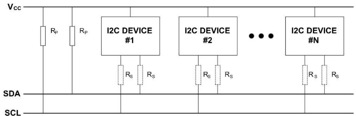
text_image
Vcc Rp Rp I2C DEVICE #1 Rs Rs I2C DEVICE #2 Rs Rs I2C DEVICE #N Rs Rs SDA SCLNote: R_s is optional
8.2.4 Transactions
The I ^2 C standard defines three fundamental transaction formats:
- Master Write
- The master transmits data packets to the slave after addressing it
- Master Read
- The slave transmits data packets to the master after being addressed
• Combined Read/Write
- A combined transaction consists of several write and read transactions
A data transfer starts with the master issuing a Start condition on the bus, followed by the address of the slave together with a bit to indicate whether the master wants to read from or write to the slave. The addressed slave must respond to this by sending an ACK back to the master.
After this, data packets are sent from the master or slave, according to the read/write bit. Each packet must be acknowledged (ACK) or not acknowledged (NACK) by the receiver.
If a slave responds with a NACK, the master must assume that the slave cannot receive any more data and cancel the write operation.
The master completes a transaction by issuing a Stop condition.
A master can issue multiple Start conditions during a transaction; this is then called a Repeated Start condition.
8.2.4.1 Address Packets
The slave address consists of seven bits. The 8th bit in the transfer determines the data direction (read or write). An address packet always succeeds a Start or Repeated Start condition. The 8th bit is handled in the driver, and the user will only have to provide the 7 bit address.
8.2.4.2 Data Packets
Data packets are nine bits long, consisting of one 8-bit data byte, and an acknowledgement bit. Data packets follow either an address packet or another data packet on the bus.
8.2.4.3 Transaction Examples
The gray bits in the following examples are sent from master to slave, and the white bits are sent from slave to master. Example of a read transaction is shown in Figure 8-2: I2C Packet Read on page 172. Here, the master first issues a Start condition and gets ownership of the bus. An address packet with the direction flag set to read is then sent and acknowledged by the slave. Then the slave sends one data packet which is acknowledged by the master. The slave sends another packet, which is not acknowledged by the master and indicates that the master will terminate the transaction. In the end, the transaction is terminated by the master issuing a Stop condition.
Figure 8-2. I2C Packet Read
| Dil 0 | Dil 1 | Dil 2 | Dil 3 | Dil 4 | Dil 5 | Dil 6 | Dil 7 | Dil 8 | Dil 9 | Dil 10 | Dil 11 | Dil 12 | Dil 13 | Dil 14 | Dil 15 | Dil 16 | Dil 17 | Dil 18 | Dil 19 | Dil 20 | Dil 21 | Dil 22 | Dil 23 | Dil 24 | Dil 25 | Dil 26 | Dil 27 | Dil 28 |
| START | ADDRESS | READ | ACK | DATA | ACK | DATA | NACK | STOP | ||||||||||||||||||||
Example of a write transaction is shown in Figure 8-3: I2C Packet Write on page 172. Here, the master first issues a Start condition and gets ownership of the bus. An address packet with the dir flag set to write is then sent and acknowledged by the slave. Then the master sends two data packets, each acknowledged by the slave. In the end, the transaction is terminated by the master issuing a Stop condition.
Figure 8-3. I2C Packet Write
| Bit 0 | Bit 1 | Bit 2 | Bit 3 | Bit 4 | Bit 5 | Bit 6 | Bit 7 | Bit 8 | Bit 9 | Bit 10 | Bit 11 | Bit 12 | Bit 13 | Bit 14 | Bit 15 | Bit 16 | Bit 17 | Bit 18 | Bit 19 | Bit 20 | Bit 21 | Bit 22 | Bit 23 | Bit 24 | Bit 25 | Bit 26 | Bit 27 | Bit 28 |
| START | ADDRESS | WRITE | ACK | DATA | ACK | DATA | ACK | STOP | ||||||||||||||||||||
8.2.4.4 Packet Timeout
When a master sends an I²C packet, there is no way of being sure that a slave will acknowledge the packet. To avoid stalling the device forever while waiting for an acknowledge, a user selectable timeout is provided in the i2c_master_config struct which lets the driver exit a read or write operation after the specified time. The function will then return the STATUS_ERR_TIMEOUT flag.
This is also the case for the slave when using the functions postfixed _wait.
The time before the timeout occurs, will be the same as for unknown bus state timeout.
8.2.4.5 Repeated Start
To issue a Repeated Start, the functions postfixed _no_stop must be used. These functions will not send a Stop condition when the transfer is done, thus the next transfer will start with a Repeated Start. To end the transaction, the functions without the _no_stop postfix must be used for the last read/write.
8.2.5 Multi Master
In a multi master environment, arbitration of the bus is important, as only one master can own the bus at any point.
8.2.5.1 Arbitration
Clock stretching
The serial clock line is always driven by a master device. However, all devices connected to the bus are allowed stretch the low period of the clock to slow down the overall clock frequency or to insert wait states while processing data. Both master and slave can randomly stretch the clock, which will force the other device into a wait-state until the clock line goes high again.
Arbitration on the data line
If two masters start transmitting at the same time, they will both transmit until one master detects that the other master is pulling the data line low. When this is detected, the master not pulling the line low, will stop the transmission and wait until the bus is idle. As it is the master trying to contact the slave with the lowest address that will get the bus ownership, this will create an arbitration scheme always prioritizing the slaves with the lowest address in case of a bus collision.
8.2.5.2 Clock Synchronization
In situations where more than one master is trying to control the bus clock line at the same time, a clock synchronization algorithm based on the same principles used for clock stretching is necessary.
8.2.6 Bus States
As the I²C bus is limited to one transaction at the time, a master that wants to perform a bus transaction must wait until the bus is free. Because of this, it is necessary for all masters in a multi-master system to know the current status of the bus to be able to avoid conflicts and to ensure data integrity.
• IDLE No activity on the bus (between a Stop and a new Start condition)
- OWNER If the master initiates a transaction successfully
- BUSY If another master is driving the bus
- UNKNOWN If the master has recently been enabled or connected to the bus. Is forced to IDLE after given timeout when the master module is enabled.
The bus state diagram can be seen in Figure 8-4: I2C bus state diagram on page 174.
S: Start condition
- P: Stop condition
• Sr: Repeated start condition
Figure 8-4. I2C bus state diagram
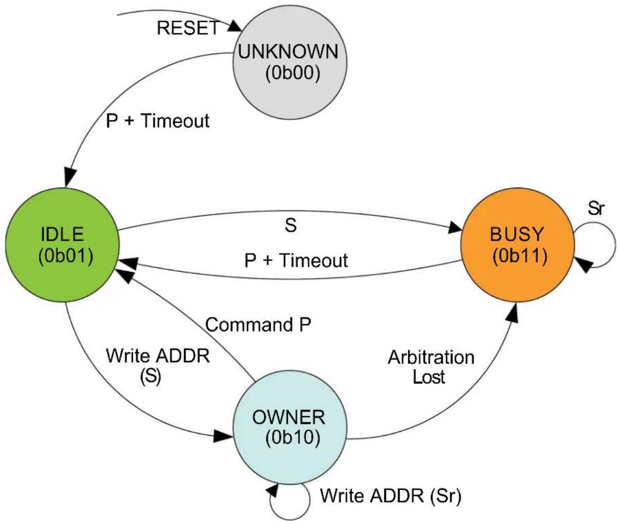
flowchart
graph TD
A["IDLE (0b01)"] -->|P + Timeout| B["UNKNOWN (0b00)"]
A -->|S P + Timeout| C["BUSY (0b11)"]
A -->|Command P| D["OWNER (0b10)"]
D -->|Arbitration Lost| C
C -->|Sr| D
D -->|Write ADDR (Sr)| A
A -->|RESET| B
8.2.7 Bus Timing
Inactive bus timeout for the master and SDA hold time is configurable in the drivers.
8.2.7.1 Unknown Bus State Timeout
When a master is enabled or connected to the bus, the bus state will be unknown until either a given timeout or a stop command has occurred. The timeout is configurable in the i2c_master_config struct. The timeout time will depend on toolchain and optimization level used, as the timeout is a loop incrementing a value until it reaches the specified timeout value.
8.2.7.2 SDA Hold Timeout
When using the I ^2 C in slave mode, it will be important to set a SDA hold time which assures that the master will be able to pick up the bit sent from the slave. The SDA hold time makes sure that this is the case by holding the data line low for a given period after the negative edge on the clock.
The SDA hold time is also available for the master driver, but is not a necessity.
8.2.8 Operation in Sleep Modes
The I ^2 C module can operate in all sleep modes by setting the run_in_standby boolean in the i2c_master_config or i2c_slave_config struct. The operation in slave and master mode is shown in Table 8-1: I2C standby operations on page 175.
Table 8-1. I2C standby operations
| Run in standby Slave Master | ||
| false Disabled, all reception is dropped | GCLK disabled when master is idle | |
| true Wake on address match when enabled | GCLK enabled while in sleep modes | |
8.3 Special Considerations
8.3.1 Interrupt-Driven Operation
While an interrupt-driven operation is in progress, subsequent calls to a write or read operation will return the STATUS_BUSY flag, indicating that only one operation is allowed at any given time.
To check if another transmission can be initiated, the user can either call another transfer operation, or use the i2c_master_get_job_status/i2c_slave_get_job_status functions depending on mode.
If the user would like to get callback from operations while using the interrupt-driven driver, the callback must be registered and then enabled using the "register_callback" and "enable_callback" functions.
8.4 Extra Information
For extra information see Extra Information for SERCOM I2C Driver. This includes:
• Acronyms
- Dependencies
- Errata
- Module History
8.5 Examples
For a list of examples related to this driver, see Examples for SERCOM I2C Driver.
8.6 API Overview
8.6.1 Structure Definitions
8.6.1.1 Struct i2c_master_config
This is the configuration structure for the I ^2 C Master device. It is used as an argument for i2c_master_init to provide the desired configurations for the module. The structure should be initialized using the i2c_master_get_config_defaults.
Table 8-2. Members
| Type Name Description | ||
| uint32_t baud_rate Baud rate (in KHZ) for I2C | operations in standard-mode,Fast-mode and Fast-mode PlusTransfers, i2c_master_baud_rate | |
| uint16_t buffer_timeout | Timeout for packet write to wait for slave | |
| enum gclk_generator | generator_source | GCLK generator to use as clock source |
| enum i2c_master_inactive_timeout | inactive_timeout | Inactive bus time out |
| uint32_t pinmux_pad0 | PAD0 (SDA) pinmux | |
| uint32_t pinmux_pad1 | PAD1 (SCL) pinmux | |
| bool run_in_standby Set to keep module active in sleep | modes | |
| bool scl_low_timeout Set to enable SCL low time-out | ||
| enum i2c_master_start_hold_time start_hold_time Bus hold time after start signal on data line | ||
| uint16_t unknown_bus_state_timeout Unknown bus state timeout | ||
8.6.1.2 Struct i2c\_master\_module
SERCOM I²C Master driver software instance structure, used to retain software state information of an associated hardware module instance.
Note
The fields of this structure should not be altered by the user application; they are reserved for module-internal use only.
8.6.1.3 Struct i2c\_master\_packet
Structure to be used when transferring I ^2 C master packets.
Table 8-3. Members
| Type Name Description | ||
| uint16_t address Address to slave device | ||
| uint8_t * data Data array containing all data to be | transferred | |
| uint16_t data_length Length of data array | ||
| bool high_speed Use high speed transfer. Set to | false if the feature is not supported by the device | |
| uint8_t hs_master_code High speed mode master | code (0000 1XXX), valid when high_speed is true | |
| bool ten_bit_address Use 10 bit addressing. Set to false | if the feature is not supported by the device | |
8.6.1.4 Struct i2c\_slave\_config
This is the configuration structure for the I2C Slave device. It is used as an argument for i2c_slave_init to provide the desired configurations for the module. The structure should be initialized using the i2c_slave_get_config_defaults.
Table 8-4. Members
| Type Name Description | ||
| uint16_t address Address or upper limit of address | range | |
| uint16_t address_mask | Address mask, second address or lower limit of address range | |
| enum i2c_slave_address_mode | address_mode | Addressing mode |
| uint16_t buffer_timeout Timeout to wait for master in polled | functions | |
| bool enable_general_call_address Enable general call address | recognition (general call address is defined as 0000000 with direction bit 0) | |
| bool enable_nack_on_address Enable NACK on address | match (this can be changed after initialization via the i2c_slave_enable_nack_on_address and i2c_slave_disable_nack_on_address functions) | |
| bool enable_scl_low_timeout Set to enable the SCL low timeout | ||
| enum gclk_generator generator_source GCLK generator to use as clock | source | |
| uint32_t pinmux_pad0 PAD0 (SDA) pinmux | ||
| uint32_t pinmux_pad1 PAD1 (SCL) pinmux | ||
| bool run_in_standby Set to keep module active in sleep | modes | |
| bool scl_low_timeout Set to enable SCL low time-out | ||
| enum i2c_slave_sda_hold_time | sda_hold_time | SDA hold time with respect to the negative edge of SCL |
8.6.1.5 Struct i2c\_slave\_module
SERCOM I²C Slave driver software instance structure, used to retain software state information of an associated hardware module instance.
Note
The fields of this structure should not be altered by the user application; they are reserved for module-internal use only.
8.6.1.6 Struct i2c\_slave\_packet
Structure to be used when transferring I ^2 C slave packets.
Table 8-5. Members
| Type Name Description | ||
| uint8_t * | data | Data array containing all data to be transferred |
| uint16_t data_length | Length of data array |
8.6.2 Macro Definitions
8.6.2.1 I2C slave status flags
I2C slave status flags, returned by i2c_slave_get_status() and cleared by i2c_slave_clear_status().
Macro I2C_SLAVE_STATUS_ADDRESS_MATCH
#define I2C_SLAVE_STATUS_ADDRESS_MATCH (1UL << 0)
Address Match
Note
Should only be cleared internally by driver.
Macro I2C_SLAVE_STATUS_DATA_READY
#define I2C_SLAVE_STATUS_DATA_READY (1UL << 1)
Data Ready
Macro I2C_SLAVE_STATUS_STOP_RECEIVED
#define I2C_SLAVE_STATUS_STOP_RECEIVED (1UL << 2)
Stop Received
Macro I2C_SLAVE_STATUS_CLOCK_HOLD
#define I2C_SLAVE_STATUS_CLOCK_HOLD (1UL << 3)
Clock Hold
Note
Cannot be cleared, only valid when I2C_SLAVE_STATUS_ADDRESS_MATCH is set
Macro I2C_SLAVE_STATUS_SCL_LOW_TIMEOUT
#define I2C_SLAVE_STATUS_SCL_LOW_TIMEOUT (1UL << 4)
SCL Low Timeout
Macro I2C_SLAVE_STATUS_REPEATED_START
#define I2C_SLAVE_STATUS_REPEATED_START (1UL << 5)
Repeated Start
Note
Cannot be cleared, only valid when I2C_SLAVE_STATUS_ADDRESS_MATCH is set
Macro I2C_SLAVE_STATUS_RECEIVED_NACK
#define I2C_SLAVE_STATUS_RECEIVED_NACK (1UL << 6)
Received not acknowledge
Note
Cannot be cleared
Macro I2C_SLAVE_STATUS_COLLISION
#define I2C_SLAVE_STATUS_COLLISION (1UL << 7)
Transmit Collision
Macro I2C_SLAVE_STATUS_BUS_ERROR
#define I2C_SLAVE_STATUS_BUS_ERROR (1UL << 8)
Bus error
8.6.3 Function Definitions
8.6.3.1 Lock/Unlock
Function i2c_master_lock()
Attempt to get lock on driver instance.
enum status_code i2c_master_lock(
struct i2c_master_module *const module)
This function checks the instance's lock, which indicates whether or not it is currently in use, and sets the lock if it was not already set.
The purpose of this is to enable exclusive access to driver instances, so that, e.g., transactions by different services will not interfere with each other.
Table 8-6. Parameters
| Data direction Parameter name Description | |
| [in, out] module Pointer to the driver instance to | lock. |
Table 8-7. Return Values
| Return value Description | |
| STATUS_OK if the module was locked. | |
| STATUS_BUSY if the module was already locked. |
Function i2c\_master\_unlock()
Unlock driver instance.
void i2c_master_unlock(
struct i2c_master_module *const module)
This function clears the instance lock, indicating that it is available for use.
Table 8-8. Parameters
| Data direction Parameter name Description | |
| [in, out] module Pointer to the driver instance to | lock. |
Table 8-9. Return Values
| Return value Description | |
| STATUS_OK if the module was locked. | |
| STATUS_BUSY if the module was already locked. |
8.6.3.2 Configuration and Initialization
Function i2c\_master\_is\_syncing()
Returns the synchronization status of the module.
bool i2c_master_is_syncing(
const struct i2c_master_module *const module)
Returns the synchronization status of the module.
Table 8-10. Parameters
| Data direction Parameter name Description | |
| [in] module Pointer to software module | structure |
Returns
Status of the synchronization.
Table 8-11. Return Values
| Return value Description | |
| true Module is busy synchronizing | |
| false Module is not synchronizing |
Function i2c\_master\_get\_config\_defaults()
Gets the I2C master default configurations.
void i2c_master_get_config_defaults(
struct i2c_master_config *const config)
Use to initialize the configuration structure to known default values.
The default configuration is as follows:
- Baudrate 100kHz
• GCLK generator 0 - Do not run in standby
• Start bit hold time 300ns-600ns
• Buffer timeout = 65535
• Unknown bus status timeout = 65535 - Do not run in standby
• PINMUX_DEFAULT for SERCOM pads
Those default configuration only available if the device supports it:
• High speed baudrate 3.4MHz
- Standard-mode and Fast-mode transfer speed
• SCL stretch disabled
- slave SCL low extend time-out disabled
- maser SCL low extend time-out disabled
Table 8-12. Parameters
| Data direction Parameter name Description | |
| [out] config Pointer to configuration structure to | be initiated |
Function i2c\_master\_init()
Initializes the requested I2C hardware module.
enum status_code i2c_master_init(
struct i2c_master_module *const module,
Sercom *const hw,
const struct i2c_master_config *const config)
Initializes the SERCOM I ^2 C master device requested and sets the provided software module struct. Run this function before any further use of the driver.
Table 8-13. Parameters
| Data direction Parameter name Description | |
| [out] module Pointer to software module struct | |
| [in] hw Pointer to the hardware instance | |
| [in] config Pointer to the configuration struct |
Returns
Status of initialization.
Table 8-14. Return Values
| Return value Description | |
| STATUS_OK Module initiated correctly | |
| STATUS_ERR_DENIED If module is enabled | |
| STATUS_BUSY If module is busy resetting | |
| STATUS_ERR_ALREADY_INITIALIZED If setting other GCLK generator than previously set | |
| STATUS_ERR_BAUDRATE_UNAVAILABLE If given baudrate is not compatible with set GCLK frequency | |
Function i2c\_master\_enable()
Enables the I2C module.
void i2c_master_enable( const struct i2c_master_module *const module)
Enables the requested I²C module and set the bus state to IDLE after the specified timeout period if no stop bit is detected.
Table 8-15. Parameters
| Data direction Parameter name Description | |
| [in] module Pointer to the software module | struct |
Function i2c\_master\_disable()
Disable the I2C module.
void i2c_master_disable(
const struct i2c_master_module *const module)
Disables the requested I²C module.
Table 8-16. Parameters
| Data direction Parameter name Description | |
| [in] module Pointer to the software module | struct |
Function i2c\_master\_reset()
Resets the hardware module.
void i2c_master_reset(
struct i2c_master_module *const module)
Reset the module to hardware defaults.
Table 8-17. Parameters
| Data direction Parameter name Description | |
| [in, out] module Pointer to software module | structure |
8.6.3.3 Read and Write
Function i2c\_master\_read\_packet\_wait()
Reads data packet from slave.
enum status_code i2c_master_read_packet_wait(
struct i2c_master_module *const module,
struct i2c_master_packet *const packet)
Reads a data packet from the specified slave address on the I ^2 C bus and sends a stop condition when finished.
Note
This will stall the device from any other operation. For interrupt-driven operation, see i2c_master_read_packet_job.
Table 8-18. Parameters
| Data direction Parameter name Description | |
| [in, out] module Pointer to software module struct | |
| [in, out] packet Pointer to I | ^2C packet to transfer |
Returns
Status of reading packet.
Table 8-19. Return Values
| Return value Description | |
| STATUS_OK The packet was read successfully | |
| STATUS_ERR_TIMEOUT If no response was given within specified timeout period | |
| STATUS_ERR_DENIED If error on bus | |
| STATUS_ERR_PACKET_COLLISION If arbitration is lost | |
| STATUS_ERR_BAD_ADDRESS If slave is busy, or no slave acknowledged the address | |
Function i2c\_master\_read\_packet\_wait\_no\_stop()
Reads data packet from slave without sending a stop condition when done.
enum status_code i2c_master_read_packet_wait_no_stop(
struct i2c_master_module *const module,
struct i2c_master_packet *const packet)
Reads a data packet from the specified slave address on the I²C bus without sending a stop condition when done, thus retaining ownership of the bus when done. To end the transaction, a read or write with stop condition must be performed.
Note
This will stall the device from any other operation. For interrupt-driven operation, see i2c_master_read_packet_job.
Table 8-20. Parameters
| Data direction Parameter name Description | |
| [in, out] module Pointer to software module struct | |
| [in, out] packet Pointer to I | ^2C packet to transfer |
Returns
Status of reading packet.
Table 8-21. Return Values
| Return value Description | |
| STATUS_OK The packet was read successfully | |
| STATUS_ERR_TIMEOUT If no response was given within specified timeout period | |
| STATUS_ERR_DENIED If error on bus | |
| STATUS_ERR_PACKET_COLLISION If arbitration is lost | |
| STATUS_ERR_BAD_ADDRESS If slave is busy, or no slave acknowledged the address | |
Function i2c\_master\_write\_packet\_wait()
Writes data packet to slave.
enum status_code i2c_master_write_packet_wait(
struct i2c_master_module *const module,
struct i2c_master_packet *const packet)
Writes a data packet to the specified slave address on the I²C bus and sends a stop condition when finished.
Note
This will stall the device from any other operation. For interrupt-driven operation, see i2c_master_read_packet_job.
Table 8-22. Parameters
| Data direction Parameter name Description | |
| [in, out] module Pointer to software module struct | |
| [in, out] packet Pointer to I | ^2C packet to transfer |
Returns
Status of reading packet.
Table 8-23. Return Values
| Return value Description | |
| STATUS_OK If packet was read | |
| STATUS_BUSY If master module is busy with a job | |
| STATUS_ERR_DENIED If error on bus | |
| STATUS_ERR_PACKET_COLLISION If arbitration is lost | |
| STATUS_ERR_BAD_ADDRESS If slave is busy, or no slave acknowledged the address | |
| STATUS_ERR_TIMEOUT If timeout occurred | |
| STATUS_ERR_OVERFLOW If slave did not acknowledge last sent data, indicating that slave does not want more data and was not able to read last data sent | |
Function i2c\_master\_write\_packet\_wait\_no\_stop()
Writes data packet to slave without sending a stop condition when done.
enum status_code i2c_master_write_packet_wait_no_stop(
struct i2c_master_module *const module,
struct i2c_master_packet *const packet)
Writes a data packet to the specified slave address on the I²C bus without sending a stop condition, thus retaining ownership of the bus when done. To end the transaction, a read or write with stop condition or sending a stop with the i2c_master_send_stop function must be performed.
Note
This will stall the device from any other operation. For interrupt-driven operation, see i2c_master_read_packet_job.
Table 8-24. Parameters
| Data direction Parameter name Description | |
| [in, out] module Pointer to software module struct | |
| [in, out] packet Pointer to I | ^2C packet to transfer |
Returns
Status of reading packet.
Table 8-25. Return Values
| Return value Description | |
| STATUS_OK If packet was read | |
| STATUS_BUSY If master module is busy | |
| STATUS_ERR_DENIED If error on bus | |
| STATUS_ERR_PACKET_COLLISION If arbitration is lost | |
| STATUS_ERR_BAD_ADDRESS If slave is busy, or no slave acknowledged the address | |
| STATUS_ERR_TIMEOUT If timeout occurred | |
| STATUS_ERR_OVERFLOW If slave did not acknowledge last sent data, indicating that slave do not want more data | |
Function i2c\_master\_send\_stop()
Sends stop condition on bus.
void i2c_master_send_stop(
struct i2c_master_module *const module)
Sends a stop condition on bus.
Note
This function can only be used after the i2c_master_write_packet_wait_no_stop function. If a stop condition is to be sent after a read, the i2c_master_read_packet_wait function must be used.
Table 8-26. Parameters
| Data direction Parameter name Description | |
| [in] module Pointer to the software instance | struct |
8.6.3.4 Callbacks
Function i2c\_master\_register\_callback()
Registers callback for the specified callback type.
void i2c_master_register_callback(
struct i2c_master_module *const module,
i2c_master_callback_t callback,
enum i2c_master_callback callback_type)
Associates the given callback function with the specified callback type.
To enable the callback, the i2c_master_enable_callback function must be used.
Table 8-27. Parameters
| Data direction Parameter name Description | |
| [in, out] module Pointer to the software module | struct |
| [in] callback Pointer to the function desired for | the specified callback |
| [in] callback_type Callback type to register |
Function i2c\_master\_unregister\_callback()
Unregisters callback for the specified callback type.
void i2c_master_unregister_callback(
struct i2c_master_module *const module,
enum i2c_master_callback callback_type)
When called, the currently registered callback for the given callback type will be removed.
Table 8-28. Parameters
| Data direction Parameter name Description | |
| [in, out] module Pointer to the software module | struct |
| [in] callback_type Specifies the callback type to | unregister |
Function i2c\_master\_enable\_callback()
Enables callback.
void i2c_master_enable_callback(
struct i2c_master_module *const module,
enum i2c_master_callback callback_type)
Enables the callback specified by the callback_type.
Table 8-29. Parameters
| Data direction Parameter name Description | |
| [in, out] module Pointer to the software module | struct |
| [in] callback_type Callback type to enable |
Function i2c\_master\_disable\_callback()
Disables callback.
void i2c_master_disable_callback(
struct i2c_master_module *const module,
enum i2c_master_callback callback_type)
Disables the callback specified by the callback_type.
Table 8-30. Parameters
| Data direction Parameter name Description | |
| [in, out] module Pointer to the software module | struct |
| [in] callback_type Callback type to disable |
8.6.3.5 Read and Write, Interrupt-Driven
Function i2c\_master\_read\_packet\_job()
Initiates a read packet operation.
enum status_code i2c_master_read_packet_job(
struct i2c_master_module *const module,
struct i2c_master_packet *const packet)
Reads a data packet from the specified slave address on the I²C bus. This is the non-blocking equivalent of i2c_master_read_packet_wait.
Table 8-31. Parameters
| Data direction Parameter name Description | |
| [in, out] module Pointer to software module struct | |
| [in, out] packet Pointer to I | ^2C packet to transfer |
Returns
Status of starting reading I ^2 C packet.
Table 8-32. Return Values
| Return value Description | |
| STATUS_OK If reading was started successfully | |
| STATUS_BUSY If module is currently busy with another transfer |
Function i2c\_master\_read\_packet\_job\_no\_stop()
Initiates a read packet operation without sending a STOP condition when done.
enum status_code i2c_master_read_packet_job_no_stop(
struct i2c_master_module *const module,
struct i2c_master_packet *const packet)
Reads a data packet from the specified slave address on the I²C bus without sending a stop condition, thus retaining ownership of the bus when done. To end the transaction, a read or write with stop condition must be performed.
This is the non-blocking equivalent of i2c_master_read_packet_wait_no_stop.
Table 8-33. Parameters
| Data direction Parameter name Description | |
| [in, out] module Pointer to software module struct | |
| [in, out] packet Pointer to I | ^2C packet to transfer |
Returns
Status of starting reading I ^2 C packet.
Table 8-34. Return Values
| Return value Description | |
| STATUS_OK If reading was started successfully | |
| STATUS_BUSY If module is currently busy with another operation | |
Function i2c\_master\_write\_packet\_job()
Initiates a write packet operation.
enum status_code i2c_master_write_packet_job(
struct i2c_master_module *const module,
struct i2c_master_packet *const packet)
Writes a data packet to the specified slave address on the I²C bus. This is the non-blocking equivalent of i2c_master_write_packet_wait.
Table 8-35. Parameters
| Data direction Parameter name Description | |
| [in, out] module Pointer to software module struct | |
| [in, out] packet Pointer to I | ^2C packet to transfer |
Returns
Status of starting writing I ^2 C packet job.
Table 8-36. Return Values
| Return value Description | |
| STATUS_OK If writing was started successfully | |
| STATUS_BUSY If module is currently busy with another transfer |
Function i2c\_master\_write\_packet\_job\_no\_stop()
Initiates a write packet operation without sending a STOP condition when done.
enum status_code i2c_master_write_packet_job_no_stop(
struct i2c_master_module *const module,
struct i2c_master_packet *const packet)
Writes a data packet to the specified slave address on the I²C bus without sending a stop condition, thus retaining ownership of the bus when done. To end the transaction, a read or write with stop condition or sending a stop with the i2c_master_send_stop function must be performed.
This is the non-blocking equivalent of i2c_master_write_packet_wait_no_stop.
Table 8-37. Parameters
| Data direction Parameter name Description | |
| [in, out] module Pointer to software module struct | |
| [in, out] packet Pointer to I | ^2C packet to transfer |
Returns
Status of starting writing I ^2 C packet job.
Table 8-38. Return Values
| Return value Description | |
| STATUS_OK If writing was started successfully | |
| STATUS_BUSY If module is currently busy with another |
Function i2c\_master\_cancel\_job()
Cancel any currently ongoing operation.
void i2c_master_cancel_job(
struct i2c_master_module *const module)
Terminates the running transfer operation.
Table 8-39. Parameters
| Data direction Parameter name Description | |
| [in, out] module Pointer to software module | structure |
Function i2c\_master\_get\_job\_status()
Get status from ongoing job.
enum status_code i2c_master_get_job_status(struct i2c_master_module *const module)
Will return the status of a transfer operation.
Table 8-40. Parameters
| Data direction Parameter name Description | |
| [in] module Pointer to software module | structure |
Returns
Last status code from transfer operation.
Table 8-41. Return Values
| Return value Description | |
| STATUS_OK No error has occurred | |
| STATUS_BUSY If transfer is in progress | |
| STATUS_BUSY If master module is busy | |
| STATUS_ERR_DENIED If error on bus | |
| STATUS_ERR_PACKET_COLLISION If arbitration is lost | |
| STATUS_ERR_BAD_ADDRESS If slave is busy, or no slave acknowledged the address | |
| STATUS_ERR_TIMEOUT If timeout occurred | |
| STATUS_ERR_OVERFLOW If slave did not acknowledge last sent data, indicating that slave does not want more data and was not able to read | |
8.6.3.6 Lock/Unlock
Function i2c\_slave\_lock()
Attempt to get lock on driver instance.
enum status_code i2c_slave_lock(
struct i2c_slave_module *const module)
This function checks the instance's lock, which indicates whether or not it is currently in use, and sets the lock if it was not already set.
The purpose of this is to enable exclusive access to driver instances, so that, e.g., transactions by different services will not interfere with each other.
Table 8-42. Parameters
| Data direction Parameter name Description | |
| [in, out] module Pointer to the driver instance to | lock. |
Table 8-43. Return Values
| Return value Description | |
| STATUS_OK if the module was locked. | |
| STATUS_BUSY if the module was already locked. |
Function i2c\_slave\_unlock()
Unlock driver instance.
void i2c_slave_unlock(
struct i2c_slave_module *const module)
This function clears the instance lock, indicating that it is available for use.
Table 8-44. Parameters
| Data direction Parameter name Description | |
| [in, out] module Pointer to the driver instance to | lock. |
Table 8-45. Return Values
| Return value Description | |
| STATUS_OK if the module was locked. | |
| STATUS_BUSY if the module was already locked. |
8.6.3.7 Configuration and Initialization
Function i2c\_slave\_is\_syncing()
Returns the synchronization status of the module.
bool i2c_slave_is_syncing(
const struct i2c_slave_module *const module)
Returns the synchronization status of the module.
Table 8-46. Parameters
| Data direction Parameter name Description | |
| [out] module Pointer to software module | structure |
Returns
Status of the synchronization.
Table 8-47. Return Values
| Return value Description | |
| true Module is busy synchronizing | |
| false Module is not synchronizing |
Function i2c\_slave\_get\_config\_defaults()
Gets the I2C slave default configurations.
void i2c_slave_get_config_defaults(
struct i2c_slave_config *const config)
This will initialize the configuration structure to known default values.
The default configuration is as follows:
- Disable SCL low timeout
• 300ns - 600ns SDA hold time
• Buffer timeout = 65535 - Address with mask
- Address = 0
- Address mask = 0 (one single address)
- General call address disabled
- Address nack disabled if the interrupt driver is used
• GCLK generator 0 - Do not run in standby
• PINMUX_DEFAULT for SERCOM pads
Those default configuration only available if the device supports it:
• Not using 10 bit addressing
• Standard-mode and Fast-mode transfer speed
• SCL stretch disabled
• slave SCL low extend time-out disabled
Table 8-48. Parameters
| Data direction Parameter name Description | |
| [out] config Pointer to configuration structure to | be initialized |
Function i2c\_slave\_init()
Initializes the requested I2C hardware module.
enum status_code i2c_slave_init(
struct i2c_slave_module *const module,
Sercom *const hw,
const struct i2c_slave_config *const config)
Initializes the SERCOM I2C Slave device requested and sets the provided software module struct. Run this function before any further use of the driver.
Table 8-49. Parameters
| Data direction Parameter name Description | |
| [out] module Pointer to software module struct | |
| [in] hw Pointer to the hardware instance | |
| [in] config Pointer to the configuration struct |
Returns
Status of initialization.
Table 8-50. Return Values
| Return value Description | |
| STATUS_OK Module initiated correctly | |
| STATUS_ERR_DENIED If module is enabled | |
| STATUS_BUSY If module is busy resetting | |
| STATUS_ERR_ALREADY_INITIALIZED If setting other GCLK generator than previously set | |
Function i2c\_slave\_enable()
Enables the I2C module.
void i2c_slave_enable(
const struct i2c_slave_module *const module)
This will enable the requested I2C module.
Table 8-51. Parameters
| Data direction Parameter name Description | |
| [in] module Pointer to the software module | struct |
Function i2c\_slave\_disable()
Disables the I2C module.
void i2c_slave_disable(
const struct i2c_slave_module *const module)
This will disable the I2C module specified in the provided software module structure.
Table 8-52. Parameters
| Data direction Parameter name Description | |
| [in] module Pointer to the software module | struct |
Function i2c\_slave\_reset()
Resets the hardware module.
void i2c_slave_reset(
struct i2c_slave_module *const module)
This will reset the module to hardware defaults.
Table 8-53. Parameters
| Data direction Parameter name Description | |
| [in, out] module Pointer to software module | structure |
8.6.3.8 Read and Write
Function i2c\_slave\_write\_packet\_wait()
Writes a packet to the master.
enum status_code i2c_slave_write_packet_wait(
struct i2c_slave_module *const module,
struct i2c_slave_packet *const packet)
Writes a packet to the master. This will wait for the master to issue a request.
Table 8-54. Parameters
| Data direction Parameter name Description | |
| [in] module Pointer to software module | structure |
| [in] packet Packet to write to master |
Returns
Status of packet write.
Table 8-55. Return Values
| Return value Description | |
| STATUS_OK Packet was written successfully | |
| STATUS_ERR_DENIED Start condition not received, another interrupt flag is set | |
| STATUS_ERR_IO There was an error in the previous transfer | |
| STATUS_ERR_BAD_FORMAT Master wants to write data | |
| STATUS_ERR_INVALID_ARG Invalid argument(s) was provided | |
| STATUS_ERR_BUSY The I | ^2C module is busy with a job. |
| STATUS_ERR_ERR_OVERFLOW Master NACKed before entire packet was transferred | |
| STATUS_ERR_TIMEOUT No response was given within the timeout period | |
Function i2c\_slave\_read\_packet\_wait()
Reads a packet from the master.
enum status_code i2c_slave_read_packet_wait(
struct i2c_slave_module *const module,
struct i2c_slave_packet *const packet)
Reads a packet from the master. This will wait for the master to issue a request.
Table 8-56. Parameters
| Data direction Parameter name Description | |
| [in] module Pointer to software module | structure |
| [out] packet Packet to read from master |
Returns
Status of packet read.
Table 8-57. Return Values
| Return value Description | |
| STATUS_OK Packet was read successfully | |
| STATUS_ABORTED Master sent stop condition or repeated start before specified length of bytes was received | |
| STATUS_ERR_IO There was an error in the previous transfer | |
| STATUS_ERR_DENIED | Start condition not received, another interrupt flag is set |
| STATUS_ERR_INVALID_ARG Invalid argument(s) was provided | |
| STATUS_ERR_BUSY The I | ^2C module is busy with a job |
| STATUS_ERR_BAD_FORMAT | Master wants to read data |
| STATUS_ERR_ERR_OVERFLOW Last byte received overflows buffer | |
Function i2c\_slave\_get\_direction\_wait()
Waits for a start condition on the bus.
enum i2c_slave_direction i2c_slave_get_direction_wait( struct i2c_slave_module *const module)
Waits for the master to issue a start condition on the bus. Note that this function does not check for errors in the last transfer, this will be discovered when reading or writing.
Table 8-58. Parameters
| Data direction Parameter name Description | |
| [in] module Pointer to software module | structure |
Returns
Direction of the current transfer, when in slave mode.
Table 8-59. Return Values
| Return value Description | |
| I2C_SLAVE_DIRECTION_NONE No request from master within timeout period | |
| I2C_SLAVE_DIRECTION_READ Write request from master | |
| I2C_SLAVE_DIRECTION_WRITE Read request from master | |
Note
This function is only available for 7-bit slave addressing.
Waits for the master to issue a start condition on the bus. Note that this function does not check for errors in the last transfer, this will be discovered when reading or writing.
Table 8-60. Parameters
| Data direction Parameter name Description | |
| [in] module Pointer to software module | structure |
Returns
Direction of the current transfer, when in slave mode.
Table 8-61. Return Values
| Return value Description | |
| I2C_SLAVE_DIRECTION_NONE No request from master within timeout period | |
| I2C_SLAVE_DIRECTION_READ Write request from master | |
| I2C_SLAVE_DIRECTION_WRITE Read request from master | |
8.6.3.9 Status Management
Function i2c\_slave\_get\_status()
Retrieves the current module status.
uint32_t i2c_slave_get_status(
struct i2c_slave_module *const module)
Checks the status of the module and returns it as a bitmask of status flags
Table 8-62. Parameters
| Data direction Parameter name Description | |
| [in] module Pointer to the I2C slave software | device struct |
Returns
Bitmask of status flags
Table 8-63. Return Values
| Return value Description | |
| I2C_SLAVE_STATUS_ADDRESS_MATCH A valid address has been received | |
| I2C_SLAVE_STATUS_DATA_READY A I2C slave byte transmission is successfully completed | |
| I2C_SLAVE_STATUS_STOP_RECEIVED A stop condition is detected for a transaction being processed | |
| I2C_SLAVE_STATUS_CLOCK_HOLD The slave is holding the SCL line low | |
| I2C_SLAVE_STATUS_SCL_LOW_TIMEOUT An SCL low time-out has occurred | |
| I2C_SLAVE_STATUS_REPEATED_START Indicates a repeated start, only valid if I2C_SLAVE_STATUS_ADDRESS_MATCH is set | |
| I2C_SLAVE_STATUS_RECEIVED_NACK The last data packet sent was not acknowledged | |
| I2C_SLAVE_STATUS_COLLISION The I2C slave was not able to transmit a high data or NACK bit | |
| I2C_SLAVE_STATUS_BUS_ERROR An illegal bus condition has occurred on the bus | |
Function i2c\_slave\_clear\_status()
Clears a module status flag.
void i2c_slave_clear_status(
struct i2c_slave_module *const module,
uint32_t status_flags)
Clears the given status flag of the module.
Note
Not all status flags can be cleared.
Table 8-64. Parameters
| Data direction Parameter name Description | ||
| [in] module Pointer to the I2C software device | struct | |
| [in] status_flags | Bit mask of status flags to clear | |
8.6.3.10 Address Match Functionality
Function i2c\_slave\_enable\_nack\_on\_address()
Enables sending of NACK on address match.
void i2c_slave_enable_nack_on_address(struct i2c_slave_module *const module)
Enables sending of NACK on address match, thus discarding any incoming transaction.
Table 8-65. Parameters
| Data direction Parameter name Description | |
| [in, out] module Pointer to software module | structure |
Function i2c\_slave\_disable\_nack\_on\_address()
Disables sending NACK on address match.
void i2c_slave_disable_nack_on_address(struct i2c_slave_module *const module)
Disables sending of NACK on address match, thus acknowledging incoming transactions.
Table 8-66. Parameters
| Data direction Parameter name Description | |
| [in, out] module Pointer to software module | structure |
8.6.3.11 Callbacks
Function i2c\_slave\_register\_callback()
Registers callback for the specified callback type.
void i2c_slave_register_callback(
struct i2c_slave_module *const module,
i2c_slave_callback_t callback,
enum i2c_slave_callback callback_type)
Associates the given callback function with the specified callback type. To enable the callback, the i2c_slave_enable_callback function must be used.
Table 8-67. Parameters
| Data direction Parameter name Description | |
| [in, out] module Pointer to the software module | struct |
| [in] callback Pointer to the function desired for | the specified callback |
| [in] callback_type Callback type to register |
Function i2c\_slave\_unregister\_callback()
Unregisters callback for the specified callback type.
void i2c_slave_unregister_callback(
struct i2c_slave_module *const module,
enum i2c_slave_callback callback_type)
Removes the currently registered callback for the given callback type.
Table 8-68. Parameters
| Data direction Parameter name Description | |
| [in, out] module Pointer to the software module | struct |
| [in] callback_type Callback type to unregister |
Function i2c\_slave\_enable\_callback()
Enables callback.
void i2c_slave_enable_callback(
struct i2c_slave_module *const module,
enum i2c_slave_callback callback_type)
Enables the callback specified by the callback_type.
Table 8-69. Parameters
| Data direction Parameter name Description | |
| [in, out] module Pointer to the software module | struct |
| [in] callback_type Callback type to enable |
Function i2c\_slave\_disable\_callback()
Disables callback.
void i2c_slave_disable_callback(
struct i2c_slave_module *const module,
enum i2c_slave_callback callback_type)
Disables the callback specified by the callback_type.
Table 8-70. Parameters
| Data direction Parameter name Description | |
| [in, out] module Pointer to the software module | struct |
| [in] callback_type Callback type to disable |
8.6.3.12 Read and Write, Interrupt-Driven
Function i2c\_slave\_read\_packet\_job()
Initiates a reads packet operation.
enum status_code i2c_slave_read_packet_job(
struct i2c_slave_module *const module,
struct i2c_slave_packet *const packet)
Reads a data packet from the master. A write request must be initiated by the master before the packet can be read.
The I2C_SLAVE_CALLBACK_WRITE_REQUEST on page 203 callback can be used to call this function.
Table 8-71. Parameters
| Data direction Parameter name Description | |
| [in, out] module Pointer to software module struct | |
| [in, out] packet Pointer to I | ^2C packet to transfer |
Returns
Status of starting asynchronously reading I^2C packet.
Table 8-72. Return Values
| Return value Description | |
| STATUS_OK If reading was started successfully | |
| STATUS_BUSY If module is currently busy with another transfer | |
Function i2c\_slave\_write\_packet\_job()
Initiates a write packet operation.
enum status_code i2c_slave_write_packet_job(
struct i2c_slave_module *const module,
struct i2c_slave_packet *const packet)
Writes a data packet to the master. A read request must be initiated by the master before the packet can be written.
The I2C_SLAVE_CALLBACK_READ_REQUEST on page 203 callback can be used to call this function.
Table 8-73. Parameters
| Data direction Parameter name Description | |
| [in, out] module Pointer to software module struct | |
| [in, out] packet Pointer to I | ^2C packet to transfer |
Returns
Status of starting writing I ^2 C packet.
Table 8-74. Return Values
| Return value Description | |
| STATUS_OK If writing was started successfully | |
| STATUS_BUSY If module is currently busy with another transfer |
Function i2c\_slave\_cancel\_job()
Cancels any currently ongoing operation.
void i2c_slave_cancel_job(
struct i2c_slave_module *const module)
Terminates the running transfer operation.
Table 8-75. Parameters
| Data direction Parameter name Description | |
| [in, out] module Pointer to software module | structure |
Function i2c\_slave\_get\_job\_status()
Gets status of ongoing job.
enum status_code i2c_slave_get_job_status(struct i2c_slave_module *const module)
Will return the status of the ongoing job, or the error that occurred in the last transfer operation. The status will be cleared when starting a new job.
Table 8-76. Parameters
| Data direction Parameter name Description | |
| [in, out] module Pointer to software module | structure |
Returns
Status of job.
Table 8-77. Return Values
| Return value Description | |
| STATUS_OK No error has occurred | |
| STATUS_BUSY Transfer is in progress | |
| STATUS_ERR_IO A collision, timeout or bus error happened in the last transfer | |
| STATUS_ERR_TIMEOUT A timeout occurred | |
| STATUS_ERR_OVERFLOW Data from master overflows receive buffer |
8.6.4 Enumeration Definitions
8.6.4.1 Enum i2c\_master\_baud\_rate
Values for I^2C speeds supported by the module. The driver will also support setting any other value, in which case set the value in the i2c_master_config at desired value divided by 1000.
Example: If 10kHz operation is required, give baud_rate in the configuration structure the value 10.
Table 8-78. Members
| Enum value Description | |
| I2C_MASTER_BAUD_RATE_100KHZ | Baud rate at 100kHz (Standard-mode) |
| I2C_MASTER_BAUD_RATE_400KHZ | Baud rate at 400kHz (Fast-mode) |
8.6.4.2 Enum i2c\_master\_callback
The available callback types for the I ^2 C master module.
Table 8-79. Members
| Enum value Description | |
| I2C_MASTER_CALLBACK_WRITE_COMPLETE Callback for packet write complete | |
| I2C_MASTER_CALLBACK_READ_COMPLETE Callback for packet read complete | |
| I2C_MASTER_CALLBACK_ERROR Callback for error | |
8.6.4.3 Enum i2c\_master\_inactive\_timeout
\ brief Values for inactive bus time-out.
If the inactive bus time-out is enabled and the bus is inactive for longer than the time-out setting, the bus state logic will be set to idle.
Table 8-80. Members
| Enum value Description | |
| I2C_MASTER_INACTIVE_TIMEOUT_DISABLED Inactive bus time-out disabled | |
| I2C_MASTER_INACTIVE_TIMEOUT_55US Inactive bus time-out 5-6 SCL cycle time-out (50-60us) | |
| I2C_MASTER_INACTIVE_TIMEOUT_105US Inactive bus time-out 10-11 SCL cycle time-out (100-110us) | |
| I2C_MASTER_INACTIVE_TIMEOUT_205US Inactive bus time-out 20-21 SCL cycle time-out (200-210us) | |
8.6.4.4 Enum i2c\_master\_interrupt\_flag
Flags used when reading or setting interrupt flags.
Table 8-81. Members
| Enum value Description |
| I2C_MASTER_INTERRUPT_WRITE Interrupt flag used for write |
| I2C_MASTER_INTERRUPT_READ Interrupt flag used for read |
8.6.4.5 Enum i2c\_master\_start\_hold\_time
Values for the possible I^2C master mode SDA internal hold times after start bit has been sent.
Table 8-82. Members
| Enum value Description | |
| I2C_MASTER_START_HOLD_TIME_DISABLED Internal SDA hold time disabled | |
| I2C_MASTER_START_HOLD_TIME_50NS_100NS Internal SDA hold time 50ns-100ns | |
| I2C_MASTER_START_HOLD_TIME_300NS_600NS Internal SDA hold time 300ns-600ns | |
| I2C_MASTER_START_HOLD_TIME_400NS_800NS Internal SDA hold time 400ns-800ns | |
8.6.4.6 Enum i2c\_slave\_address\_mode
Enum for the possible address modes.
Table 8-83. Members
| Enum value Description | |
| I2C_SLAVE_ADDRESS_MODE_MASK Address match on address_mask used as a mask to address | |
| I2C_SLAVE_ADDRESS_MODE_TWO_ADDRESSES Address math on both address and address_mask | |
| I2C_SLAVE_ADDRESS_MODE_RANGE Address match on range of addresses between and including address and address_mask | |
8.6.4.7 Enum i2c\_slave\_callback
The available callback types for the I2C slave.
Table 8-84. Members
| Enum value Description | |
| I2C_SLAVE_CALLBACK_WRITE_COMPLETE | Callback for packet write complete |
| I2C_SLAVE_CALLBACK_READ_COMPLETE | Callback for packet read complete |
| I2C_SLAVE_CALLBACK_READ_REQUEST | Callback for read request from master - can be used to issue a write |
| I2C_SLAVE_CALLBACK_WRITE_REQUEST | Callback for write request from master - can be used to issue a read |
| I2C_SLAVE_CALLBACK_ERROR | Callback for error |
| I2C_SLAVE_CALLBACK_ERROR_LAST_TRANSFER | Callback for error in last transfer. Discovered on a new address interrupt |
8.6.4.8 Enum i2c\_slave\_direction
Enum for the direction of a request.
Table 8-85. Members
| Enum value Description | |
| I2C_SLAVE_DIRECTION_READ Read | |
| I2C_SLAVE_DIRECTION_WRITE Write | |
| I2C_SLAVE_DIRECTION_NONE No direction |
8.6.4.9 Enum i2c\_slave\_sda\_hold\_time
Enum for the possible SDA hold times with respect to the negative edge of SCL.
Table 8-86. Members
| Enum value Description | |
| I2C_SLAVE_SDA_HOLD_TIME_DISABLED SDA hold time disabled | |
| I2C_SLAVE_SDA_HOLD_TIME_50NS_100NS | SDA hold time 50ns-100ns |
| I2C_SLAVE_SDA_HOLD_TIME_300NS_600NS | SDA hold time 300ns-600ns |
Enum value Description
I2C_SLAVE_SDA_HOLD_TIME_400NS_800NS SDA hold time 400ns-800ns
8.6.4.10 Enum i2c\_transfer\_direction
For master: transfer direction or setting direction bit in address. For slave: direction of request from master.
Table 8-87. Members
| Enum value Description | |
| I2C_TRANSFER_WRITE | |
| I2C_TRANSFER_READ |
8.7 Extra Information for SERCOM I2C Driver
8.7.1 Acronyms
Table 8-88: Acronyms on page 204 is a table listing the acronyms used in this module, along with their intended meanings.
Table 8-88. Acronyms
| Acronym Description | |
| SDA Serial Data Line | |
| SCL Serial Clock Line | |
| SERCOM Serial Communication Interface | |
| DMA Direct Memory Access |
8.7.2 Dependencies
The I ^2 C driver has the following dependencies:
• System Pin Multiplexer Driver
8.7.3 Errata
There are no errata related to this driver.
8.7.4 Module History
Table 8-89: Module History on page 204 is an overview of the module history, detailing enhancements and fixes made to the module since its first release. The current version of this corresponds to the newest version listed in Table 8-89: Module History on page 204.
Table 8-89. Module History
| Changelog |
| Added 10-bit addressing and high speed support in SAM D21. |
| Seperate structure i2c_packet into i2c_master_packet and i2c_slave packet. |
| Added support for SCL stretch and extended timeout hardware features in SAM D21. |
| Added fast mode plus support in SAM D21. |
| Fixed incorrect logical mask for determining if a bus error has occurred in I2C Slave mode. |
| Initial Release |
8.8 Examples for SERCOM I2C Driver
This is a list of the available Quick Start guides (QSGs) and example applications for SAM D20/D21 I2C Driver (SERCOM I2C). QSGs are simple examples with step-by-step instructions to configure and use this driver in a selection of use cases. Note that QSGs can be compiled as a standalone application or be added to the user application.
- Quick Start Guide for the I2C Master module - Basic Use Case
- Quick Start Guide for the I2C Master module - Callback Use Case
- Quick Start Guide for the I2C Master module - DMA Use Case
- Quick Start Guide for the I2C Slave module - Basic Use Case
- Quick Start Guide for the I2C Slave module - Callback Use Case
- Quick Start Guide for the I2C Slave module - DMA Use Case
8.8.1 Quick Start Guide for SERCOM I2C Master - Basic
In this use case, the I^2C will be used and set up as follows:
- Master mode
• 100kHz operation speed
• Not operational in standby
• 10000 packet timeout value
• 65535 unknown bus state timeout value
8.8.1.1 Prerequisites
The device must be connected to an I ^2 C slave.
8.8.1.2 Setup
Code
The following must be added to the user application:
- A sample buffer to send, a sample buffer to read:
#define DATA_LENGTH 10
static uint8_t write_buffer[DATA_LENGTH] = {
0x00, 0x01, 0x02, 0x03, 0x04, 0x05, 0x06, 0x07, 0x08, 0x09,
};
static uint8_t read_buffer[DATA_LENGTH];
- Slave address to access:
#define SLAVE_ADDRESS 0x12
• Number of times to try to send packet if it fails:
#define TIMEOUT 1000
• Globally accessible module structure:
struct i2c_master_module i2c_master_instance;
• Function for setting up the module:
void configure_i2c_master(void)
{
/* Initialize config structure and software module. */
struct i2c_master_config config_i2c_master;
i2c_master_get_config_defaults(&config_i2c_master);
/* Change buffer timeout to something longer. */
config_i2c_master.buffer_timeout = 10000;
/* Initialize and enable device with config. */
i2c_master_init(&i2c_master_instance, SERCOM2, &config_i2c_master);
i2c_master_enable(&i2c_master_instance);
}
- Add to user application main():
/* Configure device and enable. */
configure_i2c_master();
/* Timeout counter. */
uint16_t timeout = 0;
/* Init i2c packet. */
struct i2c_master_packet packet = {
.address = SLAVE_ADDRESS,
.data_length = DATA_LENGTH,
.data = write_buffer,
.ten_bit_address = false,
.high_speed = false,
.hs_master_code = 0x0,
};
Workflow
- Configure and enable module:
void configure_i2c_master(void)
{
/* Initialize config structure and software module. */
struct i2c_master_config config_i2c_master;
i2c_master_get_config_defaults(&config_i2c_master);
/* Change buffer timeout to something longer. */
config_i2c_master.buffer_timeout = 10000;
/* Initialize and enable device with config. */
i2c_master_init(&i2c_master_instance, SERCOM2, &config_i2c_master);
i2c_master_enable(&i2c_master_instance);
}
a. Create and initialize configuration structure.
struct i2c_master_config config_i2c_master;
i2c_master_get_config_defaults(&config_i2c_master);
b. Change settings in the configuration.
config_i2c_master.buffer_timeout = 10000;
c. Initialize the module with the set configurations.
i2c_master_init(&i2c_master_instance, SERCOM2, &config_i2c_master);
d. Enable the module.
i2c_master_enable(&i2c_master_instance);
- Create a variable to see when we should stop trying to send packet.
uint16_t timeout = 0;
- Create a packet to send:
struct i2c_master_packet packet = {
.address = SLAVE_ADDRESS,
.data_length = DATA_LENGTH,
.data = write_buffer,
.ten_bit_address = false,
.high_speed = false,
.hs_master_code = 0x0,
};
8.8.1.3 Implementation
Code
Add to user application main():
/* Write buffer to slave until success. */
while (i2c_master_write_packet_wait(&i2c_master_instance, &packet) != STATUS_OK) {
/* Increment timeout counter and check if timed out. */
if (timeout++ == TIMEOUT) {
break;
}
}
/* Read from slave until success. */
packet.data = read_buffer;
while (i2c_master_read_packet_wait(&i2c_master_instance, &packet) != STATUS_OK) {
/* Increment timeout counter and check if timed out. */
if (timeout++ == TIMEOUT) {
break;
}
}
Workflow
- Write packet to slave.
while (i2c_master_write_packet_wait(&i2c_master_instance, &packet) != STATUS_OK) {
/* Increment timeout counter and check if timed out. */
if (timeout++ == TIMEOUT) {
break;
}
}
The module will try to send the packet TIMEOUT number of times or until it is successfully sent.
- Read packet from slave.
packet.data = read_buffer;
while (i2c_master_read_packet_wait(&i2c_master_instance, &packet) != STATUS_OK) {
/* Increment timeout counter and check if timed out. */
if (timeout++ == TIMEOUT) {
break;
}
}
The module will try to read the packet TIMEOUT number of times or until it is successfully read.
8.8.2 Quick Start Guide for SERCOM I2C Master - Callback
In this use case, the I^2C will be used and set up as follows:
- Master mode
• 100kHz operation speed
• Not operational in standby
• 65535 unknown bus state timeout value
8.8.2.1 Prerequisites
The device must be connected to an I²C slave.
8.8.2.2 Setup
Code
The following must be added to the user application:
A sample buffer to write from, a reversed buffer to write from and length of buffers.
#define DATA_LENGTH 8
static uint8_t buffer[DATA_LENGTH] = {
0x00, 0x01, 0x02, 0x03, 0x04, 0x05, 0x06, 0x07
};
static uint8_t buffer_reversed[DATA_LENGTH] = {
0x07, 0x06, 0x05, 0x04, 0x03, 0x02, 0x01, 0x00
};
Address of slave:
#define SLAVE_ADDRESS 0x12
Globally accessible module structure:
struct i2c_master_module i2c_master_instance;
Globally accessible packet:
struct i2c_master_packet packet;
Function for setting up module:
void configure_i2c(void)
{
/* Initialize config structure and software module */
struct i2c_master_config config_i2c_master;
i2c_master_get_config_defaults(&config_i2c_master);
/* Change buffer timeout to something longer */
config_i2c_master.buffer_timeout = 65535;
/* Initialize and enable device with config */
while(i2c_master_init(&i2c_master_instance, SERCOM2, &config_i2c_master) != STATUS_OK);
i2c_master_enable(&i2c_master_instance);
}
Callback function for write complete:
void i2c_write_complete_callback(
struct i2c_master_module *const module)
{
/* Send every other packet with reversed data */
if (packet.data[0] == 0x00) {
packet.data = &buffer_reversed[0];
} else {
packet.data = &buffer[0];
}
/* Initiate new packet write */
i2c_master_write_packet_job(module, &packet);
}
Function for setting up the callback functionality of the driver:
void configure_i2c_callbacks(void)
{
/* Register callback function. */
i2c_master_register_callback(&i2c_master_instance, i2c_write_complete_callback,
I2C_MASTER_CALLBACK_WRITE_COMPLETE);
i2c_master_enable_callback(&i2c_master_instance,
I2C_MASTER_CALLBACK_WRITE_COMPLETE);
}
Add to user application main():
/* Configure device and enable. */
configure_i2c();
/* Configure callbacks and enable. */
configure_i2c_callbacks();
Workflow
- Configure and enable module.
configure_i2c();
a. Create and initialize configuration structure.
struct i2c_master_config config_i2c_master;
i2c_master_get_config_defaults(&config_i2c_master);
b. Change settings in the configuration.
config_i2c_master.buffer_timeout = 65535;
c. Initialize the module with the set configurations.
while(i2c_master_init(&i2c_master_instance, SERCOM2, &config_i2c_master) != STATUS_OK);
d. Enable the module.
i2c_master_enable(&i2c_master_instance);
- Configure callback functionality.
configure_i2c_callbacks();
a. Register write complete callback.
i2c_master_register_callback(&i2c_master_instance, i2c_write_complete_callback, I2C_MASTER_CALLBACK_WRITE_COMPLETE);
b. Enable write complete callback.
i2c_master_enable_callback(&i2c_master_instance, I2C_MASTER_CALLBACK_WRITE_COMPLETE);
- Create a packet to send to slave.
packet.address = SLAVE_ADDRESS;
packet.data_length = DATA_LENGTH;
packet.data = buffer;
8.8.2.3 Implementation
Code
Add to user application main:
while (true) {
/* Infinite loop */
}
Workflow
- Write packet to slave.
i2c_master_write_packet_job(&i2c_master_instance, &packet);
- Infinite while loop, while waiting for interaction with slave.
while (true) {
/* Infinite loop */
}
8.8.2.4 Callback
Each time a packet is sent, the callback function will be called.
Workflow
• Write complete callback:
- Send every other packet in reversed order.
if (packet.data[0] == 0x00) {
packet.data = &buffer_reversed[0];
} else {
packet.data = &buffer[0];
}
- Write new packet to slave.
i2c_master_write_packet_job(module, &packet);
8.8.3 Quick Start Guide for Using DMA with SERCOM I2C Master
The supported device list:
- SAMD21
In this use case, the I^2C will used and set up as follows: - Master mode
• 100kHz operation speed
• Not operational in standby
• 10000 packet timeout value
• 65535 unknown bus state timeout value
8.8.3.1 Prerequisites
The device must be connected to an I ^2 C slave.
8.8.3.2 Setup
Code
The following must be added to the user application:
- A sample buffer to send, number of entries to send and address of slave:
#define DATA_LENGTH 10
static uint8_t buffer[DATA_LENGTH] = {
0x00, 0x01, 0x02, 0x03, 0x04, 0x05, 0x06, 0x07, 0x08, 0x09,
};
#define SLAVE_ADDRESS 0x12
Number of times to try to send packet if it fails:
#define TIMEOUT 1000
• Globally accessible module structure:
struct i2c_master_module i2c_master_instance;
• Function for setting up the module:
static void configure_i2c_master(void)
{
/* Initialize config structure and software module. */
struct i2c_master_config config_i2c_master;
i2c_master_get_config_defaults(&config_i2c_master);
/* Change buffer timeout to something longer. */
config_i2c_master.buffer_timeout = 10000;
/* Initialize and enable device with config. */
i2c_master_init(&i2c_master_instance, SERCOM2, &config_i2c_master);
i2c_master_enable(&i2c_master_instance);
}
• Globally accessible DMA module structure:
struct dma_resource example_resource;
• Globally transfer done flag:
static volatile bool transfer_is_done = false;
• Globally accessible DMA transfer descriptor:
COMPILER_ALIGNED(16)
DmacDescriptor example_descriptor;
• Function for transfer done callback:
static void transfer_done( const struct dma_resource* const resource )
{
UNUSED(resource);
transfer_is_done = true;
}
• Function for setting up the DMA resource:
static void configure_dma_resource(struct dma_resource *resource)
{
struct dma_resource_config config;
dma_get_config_defaults(&config);
config peripheral_trigger = SERCOM2_DMAC_ID_TX;
config trigger_action = DMA_TRIGGER_ACTON_BEAT;
dma_allocate(resource, &config);
}
• Function for setting up the DMA transfer descriptor:
static void setup_dma_descriptor(DmacDescriptor *descriptor)
{
struct dma_descriptor_config descriptor_config;
dma_descriptor_get_config_defaults(&descriptor_config);
descriptor_config.beat_size = DMA_BEAT_SIZE_BYTE;
descriptor_config.dst_increment_enable = false;
descriptor_config.block_transfer_count = DATA_LENGTH;
descriptor_config.source_address = (uint32_t)buffer + DATA_LENGTH;
descriptor_config.destination_address = (uint32_t)(&i2c_master_instance.hw->I2CM.DATA.reg
dma_descriptor_createubescriptor, &descriptor_config);
}
- Add to user application main():
configure_i2c_master();
configure_dma_resource(&example_resource);
setup_dma_descriptor(&example_descriptor);
dma_add_descriptor(&example_resource, &example_descriptor);
dma_register_callback(&example_resource, transfer_done, DMA_CALLBACK_TRANSFER_DONE);
dma_enable_callback(&example_resource, DMA_CALLBACK_TRANSFER_DONE);
Workflow
Configure and enable SERCOM:
configure_i2c_master();
- Create and initialize configuration structure.
struct i2c_master_config config_i2c_master;
i2c_master_get_config_defaults(&config_i2c_master);
- Change settings in the configuration.
config_i2c_master.buffer_timeout = 10000;
- Initialize the module with the set configurations.
i2c_master_init(&i2c_master_instance, SERCOM2, &config_i2c_master);
- Enable the module.
i2c_master_enable(&i2c_master_instance);
Configure DMA
- Create a DMA resource configuration structure, which can be filled out to adjust the configuration of a single DMA transfer.
struct dma_resource_config config;
- Initialize the DMA resource configuration struct with the module's default values.
dma_get_config_defaults(&config);
Note
This should always be performed before using the configuration struct to ensure that all values are initialized to known default settings.
- Set extra configurations for the DMA resource. It is using peripheral trigger, SERCOM Tx trigger and trigger causes a transaction transfer in this example.
config peripheral_trigger = SERCOM2_DMAC_ID_TX;
config trigger_action = DMA_TRIGGER_ACTON_BEAT;
- Allocate a DMA resource with the configurations.
dma_allocate(resource, &config);
- Create a DMA transfer descriptor configuration structure, which can be filled out to adjust the configuration of a single DMA transfer.
struct dma_descriptor_config descriptor_config;
- Initialize the DMA transfer descriptor configuration struct with the module's default values.
dma_descriptor_get_config_defaults(&descriptor_config);
Note
This should always be performed before using the configuration struct to ensure that all values are initialized to known default settings.
- Set the specific parameters for a DMA transfer with transfer size, source address, destination address.
descriptor_config.beat_size = DMA_BEAT_SIZE_BYTE;
descriptor_config.dst_increment_enable = false;
descriptor_config.block_transfer_count = DATA_LENGTH;
descriptor_config.source_address = (uint32_t)buffer + DATA_LENGTH;
descriptor_config.destination_address = (uint32_t)(&i2c_master_instance.hw->I2CM.DATA.reg);
- Create the DMA transfer descriptor.
dma_descriptor_createubescriptor, &descriptor_config);
8.8.3.3 Implementation
Code
Add to user application main():
dma_start_transfer_job(&example_resource);
i2c_master_dma_set_transfer(&i2c_master_instance, SLAVE_ADDRESS, DATA_LENGTH, I2C_TRANSFER_WRITE);
while (!transfer_is_done) {
/* Wait for transfer done */
}
while (true) {
Workflow
- Start the DMA transfer job.
dma_start_transfer_job(&example_resource);
- Set the auto address length and enable flag.
i2c_master_dma_set_transfer(&i2c_master_instance, SLAVE_ADDRESS, DATA_LENGTH, I2C_TRANSFER_WRITE);
- Waiting for transfer complete
while (!transfer_is_done) {
/* Wait for transfer done */
}
- Enter an infinite loop once transfer complete.
while (true) {
}
8.8.4 Quick Start Guide for SERCOM I2C Slave - Basic
In this use case, the I^2C will be used and set up as follows:
- Slave mode
• 100kHz operation speed
• Not operational in standby
• 10000 packet timeout value
8.8.4.1 Prerequisites
The device must be connected to an I²C master.
8.8.4.2 Setup
Code
The following must be added to the user application:
A sample buffer to write from, a sample buffer to read to and length of buffers:
#define DATA_LENGTH 10
uint8_t write_buffer[DATA_LENGTH] = {
0x00, 0x01, 0x02, 0x03, 0x04, 0x05, 0x06, 0x07, 0x08, 0x09};
uint8_t read_buffer[DATA_LENGTH];
Address to respond to:
#define SLAVE_ADDRESS 0x12
Globally accessible module structure:
struct i2c_slave_module i2c_slave_instance;
Function for setting up the module.
void configure_i2c_slave(void)
{
/* Create and initialize config_i2c_slave structure */
struct i2c_slave_config config_i2c_slave;
i2c_slave_get_config_defaults(&config_i2c_slave);
/* Change address and address_mode */
config_i2c_slave.address = SLAVE_ADDRESS;
config_i2c_slave.address_mode = I2C_SLAVE_ADDRESS_MODE_MASK;
config_i2c_slave.buffer_timeout = 1000;
/* Initialize and enable device with config_i2c_slave */
i2c_slave_init(&i2c_slave_instance, SERCOM2, &config_i2c_slave);
i2c_slave_enable(&i2c_slave_instance);
}
Add to user application main():
configure_i2c_slave();
enum i2c_slave_direction dir;
struct i2c_slave_packet packet = {
.data_length = DATA_LENGTH,
.data = write_buffer,
};
Workflow
- Configure and enable module:
configure_i2c_slave();
a. Create and initialize configuration structure.
struct i2c_slave_config config_i2c_slave;
i2c_slave_get_config_defaults(&config_i2c_slave);
b. Change address and address mode settings in the configuration.
config_i2c_slave.address = SLAVE_ADDRESS;
config_i2c_slave.address_mode = I2C_SLAVE_ADDRESS_MODE_MASK;
config_i2c_slave.buffer_timeout = 1000;
c. Initialize the module with the set configurations.
i2c_slave_init(&i2c_slave_instance, SERCOM2, &config_i2c_slave);
d. Enable the module.
i2c_slave_enable(&i2c_slave_instance);
- Create variable to hold transfer direction
enum i2c_slave_direction dir;
- Create packet variable to transfer
struct i2c_slave_packet packet = {
.data_length = DATA_LENGTH,
.data = write_buffer,
};
8.8.4.3 Implementation
Code
Add to user application main:
while (true) {
/* Wait for direction from master */
dir = i2c_slave_get_direction_wait(&i2c_slave_instance);
/* Transfer packet in direction requested by master */
if (dir == I2C_SLAVE_DIRECTION_READ) {
packet.data = read_buffer;
i2c_slave_read_packet_wait(&i2c_slave_instance, &packet);
} else if (dir == I2C_SLAVE_DIRECTION_WRITE) {
packet.data = write_buffer;
i2c_slave_write_packet_wait(&i2c_slave_instance, &packet);
}
}
Workflow
- Wait for start condition from master and get transfer direction.
dir = i2c_slave_get_direction_wait(&i2c_slave_instance);
- Depending on transfer direction, set up buffer to read to or write from, and write or read from master.
if (dir == I2C_SLAVE_DIRECTION_READ) {
packet.data = read_buffer;
i2c_slave_read_packet_wait(&i2c_slave_instance, &packet);
} else if (dir == I2C_SLAVE_DIRECTION_WRITE) {
packet.data = write_buffer;
i2c_slave_write_packet_wait(&i2c_slave_instance, &packet);
}
8.8.5 Quick Start Guide for SERCOM I2C Slave - Callback
In this use case, the I^2C will be used and set up as follows:
- Slave mode
• 100kHz operation speed
• Not operational in standby
• 10000 packet timeout value
8.8.5.1 Prerequisites
The device must be connected to an I ^2 C master.
8.8.5.2 Setup
Code
The following must be added to the user application:
A sample buffer to write from, a sample buffer to read to and length of buffers:
#define DATA_LENGTH 10
static uint8_t write_buffer[DATA_LENGTH] = {
0x00, 0x01, 0x02, 0x03, 0x04, 0x05, 0x06, 0x07, 0x08, 0x09,
};
static uint8_t read_buffer [DATA_LENGTH];
Address to respond to:
#define SLAVE_ADDRESS 0x12
Globally accessible module structure:
struct i2c_slave_module i2c_slave_instance;
Globally accessible packet:
static struct i2c_slave_packet packet;
Function for setting up the module.
void configure_i2c_slave(void)
{
/* Initialize config structure and module instance. */
struct i2c_slave_config config_i2c_slave;
i2c_slave_get_config_defaults(&config_i2c_slave);
/* Change address and address_mode. */
config_i2c_slave.address = SLAVE_ADDRESS;
config_i2c_slave.address_mode = I2C_SLAVE_ADDRESS_MODE_MASK;
/* Initialize and enable device with config. */
i2c_slave_init(&i2c_slave_instance, SERCOM2, &config_i2c_slave);
i2c_slave_enable(&i2c_slave_instance);
}
Callback function for read request from a master:
void i2c_read_request_callback(
struct i2c_slave_module *const module)
{
/* Init i2c packet. */
packet.data_length = DATA_LENGTH;
packet.data = write_buffer;
/* Write buffer to master */
i2c_slave_write_packet_job(module, &packet);
}
Callback function for write request from a master:
void i2c_write_request_callback(
struct i2c_slave_module *const module)
{
/* Init i2c packet. */
packet.data_length = DATA_LENGTH;
packet.data = read_buffer;
/* Read buffer from master */
if (i2c_slave_read_packet_job(module, &packet) != STATUS_OK) {
}
}
Function for setting up the callback functionality of the driver:
void configure_i2c_slave_callbacks(void)
{
/* Register and enable callback functions */
i2c_slave_register_callback(&i2c_slave_instance, i2c_read_request_callback, I2C_SLAVE_CALLBACK_READ_REQUEST);
i2c_slave_enable_callback(&i2c_slave_instance, I2C_SLAVE_CALLBACK_READ_REQUEST);
i2c_slave_register_callback(&i2c_slave_instance, i2c_write_request_callback, I2C_SLAVE_CALLBACK_WRITE_REQUEST);
i2c_slave_enable_callback(&i2c_slave_instance, I2C_SLAVE_CALLBACK_WRITE_REQUEST);
}
Add to user application main():
/* Configure device and enable. */
configure_i2c_slave();
configure_i2c_slave_callbacks();
Workflow
- Configure and enable module:
configure_i2c_slave();
a. Create and initialize configuration structure.
struct i2c_slave_config config_i2c_slave;
i2c_slave_get_config_defaults(&config_i2c_slave);
b. Change address and address mode settings in the configuration.
config_i2c_slave.address = SLAVE_ADDRESS;
config_i2c_slave.address_mode = I2C_SLAVE_ADDRESS_MODE_MASK;
c. Initialize the module with the set configurations.
i2c_slave_init(&i2c_slave_instance, SERCOM2, &config_i2c_slave);
d. Enable the module.
i2c_slave_enable(&i2c_slave_instance);
- Register and enable callback functions.
configure_i2c_slave_callbacks();
a. Register and enable callbacks for read and write requests from master.
i2c_slave_register_callback(&i2c_slave_instance, i2c_read_request_callback,
I2C_SLAVE_CALLBACK_READ_REQUEST);
i2c_slave_enable_callback(&i2c_slave_instance,
I2C_SLAVE_CALLBACK_READ_REQUEST);
i2c_slave_register_callback(&i2c_slave_instance, i2c_write_request_callback,
I2C_SLAVE_CALLBACK_WRITE_REQUEST);
i2c_slave_enable_callback(&i2c_slave_instance,
I2C_SLAVE_CALLBACK_WRITE_REQUEST);
8.8.5.3 Implementation
Code
Add to user application main:
while (true) {
/* Infinite loop while waiting for I2C master interaction */
}
Workflow
- Infinite while loop, while waiting for interaction from master.
while (true) {
/* Infinite loop while waiting for I2C master interaction */
}
8.8.5.4 Callback
When an address packet is received, one of the callback functions will be called, depending on the DIR bit in the received packet.
Workflow
- Read request callback:
- Length of buffer and buffer to be sent to master is initialized.
packet.data_length = DATA_LENGTH;
packet.data = write_buffer;
- Write packet to master.
i2c_slave_write_packet_job(module, &packet);
- Write request callback:
- Length of buffer and buffer to be read from master is initialized.
packet.data_length = DATA_LENGTH;
packet.data = read_buffer;
- Read packet from master.
if (i2c_slave_read_packet_job(module, &packet) != STATUS_OK) {
}
8.8.6 Quick Start Guide for Using DMA with SERCOM I2C Slave
The supported device list:
• SAMD21
In this use case, the I^2C will used and set up as follows:
- Slave mode
• 100kHz operation speed
• Not operational in standby
• 65535 unknown bus state timeout value
8.8.6.1 Prerequisites
The device must be connected to an I ^2 C slave.
8.8.6.2 Setup
Code
The following must be added to the user application:
- Address to respond to:
#define SLAVE_ADDRESS 0x12
- A sample buffer to send, number of entries to send and address of slave:
#define DATA_LENGTH 10
uint8_t read_buffer[DATA_LENGTH];
• Globally accessible module structure:
struct i2c_slave_module i2c_slave_instance;
• Function for setting up the module:
void configure_i2c_slave(void)
{
/* Create and initialize config_i2c_slave structure */
struct i2c_slave_config config_i2c_slave;
i2c_slave_get_config_defaults(&config_i2c_slave);
/* Change address and address_mode */
config_i2c_slave.address = SLAVE_ADDRESS;
config_i2c_slave.address_mode = I2C_SLAVE_ADDRESS_MODE_MASK;
config_i2c_slave.buffer_timeout = 1000;
/* Initialize and enable device with config_i2c_slave */
i2c_slave_init(&i2c_slave_instance, SERCOM2, &config_i2c_slave);
i2c_slave_enable(&i2c_slave_instance);
}
- Globally accessible DMA module structure:
struct dma_resource i2c_dma_resource;
• Globally accessible DMA transfer descriptor:
COMPILER_ALIGNED(16)
DmacDescriptor i2c_dma_descriptor;
• Function for setting up the DMA resource:
void configure_dma_resource(struct dma_resource *resource)
{
struct dma_resource_config config;
dma_get_config_defaults(&config);
config peripheral_trigger = SERCOM2_DMAC_ID_RX;
config trigger_action = DMA_TRIGGER_ACTON_BEAT;
dma_allocate(resource, &config);
}
• Function for setting up the DMA transfer descriptor:
void setup_dma_descriptor(DmacDescriptor *descriptor)
{
struct dma_descriptor_config descriptor_config;
dma_descriptor_get_config_defaults(&descriptor_config);
descriptor_config.beat_size = DMA_BEAT_SIZE_BYTE;
descriptor_config.src_increment_enable = false;
descriptor_config.block_transfer_count = DATA_LENGTH;
descriptor_config.destination_address = (uint32_t)read_buffer + DATA_LENGTH;
descriptor_config.source_address = (uint32_t)(&i2c_slave_instance.hw->I2CS.DATA.reg);
dma_descriptor_createubescriptor, &descriptor_config);
}
- Add to user application main():
configure_i2c_slave();
configure_dma_resource(&i2c_dma_resource);
setup_dma_descriptor(&i2c_dma_descriptor);
dma_add_descriptor(&i2c_dma_resource, &i2c_dma_descriptor);
Workflow
Configure and enable SERCOM:
void configure_i2c_slave(void)
{
/* Create and initialize config_i2c_slave structure */
struct i2c_slave_config config_i2c_slave;
i2c_slave_get_config_defaults(&config_i2c_slave);
/* Change address and address_mode */
config_i2c_slave.address = SLAVE_ADDRESS;
config_i2c_slave.address_mode = I2C_SLAVE_ADDRESS_MODE_MASK;
config_i2c_slave.buffer_timeout = 1000;
/* Initialize and enable device with config_i2c_slave */
i2c_slave_init(&i2c_slave_instance, SERCOM2, &config_i2c_slave);
i2c_slave_enable(&i2c_slave_instance);
}
- Create and initialize configuration structure.
struct i2c_slave_config config_i2c_slave;
i2c_slave_get_config_defaults(&config_i2c_slave);
- Change settings in the configuration.
config_i2c_slave.address = SLAVE_ADDRESS;
config_i2c_slave.address_mode = I2C_SLAVE_ADDRESS_MODE_MASK;
config_i2c_slave.buffer_timeout = 1000;
- Initialize the module with the set configurations.
i2c_slave_init(&i2c_slave_instance, SERCOM2, &config_i2c_slave);
- Enable the module.
i2c_slave_enable(&i2c_slave_instance);
Configure DMA
- Create a DMA resource configuration structure, which can be filled out to adjust the configuration of a single DMA transfer.
struct dma_resource_config config;
- Initialize the DMA resource configuration struct with the module's default values.
dma_get_config_defaults(&config);
Note
This should always be performed before using the configuration struct to ensure that all values are initialized to known default settings.
- Set extra configurations for the DMA resource. It is using peripheral trigger, SERCOM RX trigger and trigger causes a beat transfer in this example.
config.peripheral_trigger = SERCOM2_DMAC_ID_RX;
config trigger_action = DMA_TRIGGER_ACTON_BEAT;
- Allocate a DMA resource with the configurations.
dma_allocate(resource, &config);
- Create a DMA transfer descriptor configuration structure, which can be filled out to adjust the configuration of a single DMA transfer.
struct dma_descriptor_config descriptor_config;
- Initialize the DMA transfer descriptor configuration struct with the module's default values.
dma_descriptor_get_config_defaults(&descriptor_config);
Note
This should always be performed before using the configuration struct to ensure that all values are initialized to known default settings.
- Set the specific parameters for a DMA transfer with transfer size, source address, destination address.
descriptor_config.beat_size = DMA_BEAT_SIZE_BYTE;
descriptor_config.src_increment_enable = false;
descriptor_config.block_transfer_count = DATA_LENGTH;
descriptor_config.destination_address = (uint32_t)read_buffer + DATA_LENGTH;
descriptor_config.source_address = (uint32_t)(&i2c_slave_instance.hw->I2CS.DATA.reg);
- Create the DMA transfer descriptor.
dma_descriptor_createubescriptor, &descriptor_config);
8.8.6.3 Implementation
Code
Add to user application main():
dma_start_transfer_job(&i2c_dma_resource);
while (true) {
if (i2c_slave_dma_read_interrupt_status(&i2c_slave_instance) & SERCOM_I2CS_INTFLAG_AMATCH) {
i2c_slave_dma_write_interrupt_status(&i2c_slave_instance, SERCOM_I2CS_INTFLAG_AMATCH);
}
}
Workflow
- Start to wait a packet from master.
dma_start_transfer_job(&i2c_dma_resource);
- Once data ready, clear the address match status.
while (true) {
if (i2c_slave_dma_read_interrupt_status(&i2c_slave_instance) &
SERCOM_I2CS_INTFLAG_AMATCH) {
i2c_slave_dma_write_interrupt_status(&i2c_slave_instance,
SERCOM_I2CS_INTFLAG_AMATCH);
}
9. SAM D20/D21 Non-Volatile Memory Driver (NVM)
This driver for SAM D20/D21 devices provides an interface for the configuration and management of non-volatile memories within the device, for partitioning, erasing, reading and writing of data.
The following peripherals are used by this module:
• NVM (Non-Volatile Memory)
The outline of this documentation is as follows:
- Prerequisites
- Module Overview
• Special Considerations
- Extra Information
- Examples
- API Overview
9.1 Prerequisites
There are no prerequisites for this module.
9.2 Module Overview
The Non-Volatile Memory (NVM) module provides an interface to the device's Non-Volatile Memory controller, so that memory pages can be written, read, erased and reconfigured in a standardized manner.
9.2.1 Memory Regions
The NVM memory space of the SAM D20/D21 devices is divided into two sections: a Main Array section, and an Auxiliary space section. The Main Array space can be configured to have an (emulated) EEPROM and/or boot loader section. The memory layout with the EEPROM and bootloader partitions is shown in Figure 9-1: Memory Regions on page 228.
Figure 9-1. Memory Regions
| End of N VM Mem ory Start of EEPROM Mem ory End of Application Mem or y | Reserved EEPROM Section |
| Application Section | |
| Start of Application Mem ory End of Bootloader Mem ory Start of NVM Mem ory | BOOT Section |
The Main Array is divided into rows and pages, where each row contains four pages. The size of each page may vary from 8-1024 bytes dependent of the device. Device specific parameters such as the page size and total number of pages in the NVM memory space are available via the nvm_get_parameters() function.
A NVM page number and address can be computed via the following equations:
$$ \text { PageNum } = (\text { RowNum } \times 4) + \text { PagePosInRow } \tag {9.1} $$
$$ \text { PageAddr } = \text { PageNum } \times \text { PageSize } \tag {9.2} $$
Figure 9-2: Memory Regions on page 228 shows an example of the memory page and address values associated with logical row 7 of the NVM memory space.
Figure 9-2. Memory Regions

text_image
Row 0x07 Page 0x1F Page 0x1E Page 0x1D Page 0x1C Add ress 0x7C0 0x780 0x740 0x7009.2.2 Region Lock Bits
As mentioned in Memory Regions, the main block of the NVM memory is divided into a number of individually addressable pages. These pages are grouped into 16 equal sized regions, where each region can be locked separately issuing an NVM_COMMAND_LOCK_REGION on page 239 command or by writing the LOCK bits in the User Row. Rows reserved for the EEPROM section are not affected by the lock bits or commands.
Note
By using the NVM_COMMAND_LOCK_REGION on page 239 or NVM_COMMAND_UNLOCK_REGION on page 239 commands the settings will remain in effect until the next device reset. By changing the default lock setting for the regions, the auxiliary space must to be written, however the adjusted configuration will not take effect until the next device reset. If the Security Bit is set, the auxiliary space cannot be written to. Clearing of the security bit can only be performed by a full chip erase.
9.2.3 Read/Write
Reading from the NVM memory can be performed using direct addressing into the NVM memory space, or by calling the nvm_read_buffer() function.
Writing to the NVM memory must be performed by the nvm_write_buffer() function - additionally, a manual page program command must be issued if the NVM controller is configured in manual page writing mode, or a buffer of data less than a full page is passed to the buffer write function.
Before a page can be updated, the associated NVM memory row must be erased first via the nvm_erase_row() function. Writing to a non-erased page will result in corrupt data being stored in the NVM memory space.
9.3 Special Considerations
9.3.1 Page Erasure
The granularity of an erase is per row, while the granularity of a write is per page. Thus, if the user application is modifying only one page of a row, the remaining pages in the row must be buffered and the row erased, as an erase is mandatory before writing to a page.
9.3.2 Clocks
The user must ensure that the driver is configured with a proper number of wait states when the CPU is running at high frequencies.
9.3.3 Security Bit
The User Row in the Auxiliary Space Cannot be read or written when the Security Bit is set. The Security Bit can be set by using passing NVM_COMMAND_SET_SECURITY_BIT on page 239 to the nvm_execute_command() function, or it will be set if one tries to access a locked region. See Region Lock Bits.
The Security Bit can only be cleared by performing a chip erase.
9.4 Extra Information
For extra information see Extra Information for NVM Driver. This includes:
- Acronyms
- Dependencies
- Errata
- Module History
9.5 Examples
For a list of examples related to this driver, see Examples for NVM Driver.
9.6 API Overview
9.6.1 Structure Definitions
9.6.1.1 Struct nvm\_config
Configuration structure for the NVM controller within the device.
Table 9-1. Members
| Type Name Description | ||
| enum nvm_cache_readmode cache_readmode Select the mode for how the cache will pre-fetch data from the flash. | ||
| bool disable_cache Setting this to true will disable the | pre-fetch cache in front of the nvm controller. | |
| bool manual_page_write Manual write mode; if enabled, | pages loaded into the NVM buffer will not be written until a separate write command is issued. If disabled, writing to the last byte in the NVM page buffer will trigger an automatic write. ^1 | |
| enum nvm_sleep_power_mode sleep_power_mode Power reduction mode during device sleep. | ||
| uint8_t wait_states Number of wait states to insert | when reading from flash, to prevent invalid data from being read at high clock frequencies. | |
Notes: ^1 If a partial page is to be written, a manual write command must be executed in either mode.
9.6.1.2 Struct nvm\_fusebits
This structure contains the layout of the first 64 bits of the user row which contains the fuse settings.
Table 9-2. Members
| Type Name Description | ||
| enum nvm_bod33_action bod33_action BOD33 Action at power on | ||
| bool bod33_enable BOD33 Enable at power on | ||
| uint8_t bod33_level BOD33 Threshold level at power | on | |
| enum nvm_bootloader_size | bootloader_size | Bootloader size. |
| enum nvm_eeprom_emulator_size | eeprom_size | EEPROM emulation area size |
| uint16_t | lockbits | NVM Lock bits |
| bool wdt_always_on | WDT Always-on at power on | |
| enum nvm_wdt_early_warning_offset | wdt_early_warning_offset | WDT Early warning interrupt time offset at power on |
| bool wdt_enable | WDT Enable at power on | |
| uint8_t wdt_timeout_period WDT Period at power on | ||
| bool | wdt_window_mode_enable_at_powe | WDT Window mode enabled at power on |
| enum nvm_wdt_window_timeout | wdt_window_timeout | WDT Window mode time-out at power on |
9.6.1.3 Struct nvm\_parameters
Structure containing the memory layout parameters of the NVM module.
Table 9-3. Members
| Type Name Description | ||
| uint32_t bootloader_number_of_pages | Size of the Bootloader memory | section configured in the NVM auxiliary memory space. |
| uint32_t eeprom_number_of_pages | Size of the emulated EEPROM | memory section configured in the NVM auxiliary memory space. |
| uint16_t nvm_number_of_pages | Number of pages in the main array. | |
| uint8_t page_size | Number of bytes per page. |
9.6.2 Function Definitions
9.6.2.1 Configuration and Initialization
Function nvm\_get\_config\_defaults()
Initializes an NVM controller configuration structure to defaults.
void nvm_get_config_defaults(
struct nvm_config *const config)
Initializes a given NVM controller configuration structure to a set of known default values. This function should be called on all new instances of these configuration structures before being modified by the user application.
The default configuration is as follows:
• Power reduction mode enabled after sleep until first NVM access
• Automatic page commit when full pages are written to
• Number of FLASH wait states left unchanged
Table 9-4. Parameters
| Data direction Parameter name Description | |
| [out] config Configuration structure to initialize | to default values |
Function nvm\_set\_config()
Sets the up the NVM hardware module based on the configuration.
enum status_code nvm_set_config( const struct nvm_config *const config)
Writes a given configuration of a NVM controller configuration to the hardware module, and initializes the internal device struct
Table 9-5. Parameters
| Data direction Parameter name Description | |
| [in] | config Configuration settings for the NVM controller |
Note
The security bit must be cleared in order successfully use this function. This can only be done by a chip erase.
Returns
Status of the configuration procedure.
Table 9-6. Return Values
| Return value Description | |
| STATUS_OK If the initialization was a success | |
| STATUS_BUSY If the module was busy when the operation was attempted | |
| STATUS_ERR_IO If the security bit has been set, preventing the EEPROM and/or auxiliary space configuration from being altered | |
Function nvm\_is\_ready()
Checks if the NVM controller is ready to accept a new command.
bool nvm_is_ready(void)
Checks the NVM controller to determine if it is currently busy execution an operation, or ready for a new command.
Returns
Busy state of the NVM controller.
Table 9-7. Return Values
| Return value Description | |
| true If the hardware module is ready for a new command | |
| false If the hardware module is busy executing a command |
9.6.2.2 NVM Access Management
Function nvm\_get\_parameters()
Reads the parameters of the NVM controller.
void nvm_get_parameters(
struct nvm_parameters *const parameters)
Retrieves the page size, number of pages and other configuration settings of the NVM region.
Table 9-8. Parameters
| Data direction Parameter name Description | |
| [out] parameters Parameter structure, which holds | page size and number of pages in the NVM memory |
Function nvm\_write\_buffer()
Writes a number of bytes to a page in the NVM memory region.
enum status_code nvm_write_buffer(
const uint32_t destination_address,
const uint8_t * buffer,
uint16_t length)
Writes from a buffer to a given page address in the NVM memory.
Table 9-9. Parameters
| Data direction Parameter name Description | |
| [in] destination_address Destination page address to write | to |
| [in] buffer Pointer to buffer where the data to | write is stored |
| [in] length Number of bytes in the page to | write |
Note
If writing to a page that has previously been written to, the page's row should be erased (via nvm_erase_row()) before attempting to write new data to the page.
Returns
Status of the attempt to write a page.
Table 9-10. Return Values
| Return value Description | |
| STATUS_OK Requested NVM memory page was successfully read | |
| STATUS_BUSY NVM controller was busy when the operation was attempted | |
| STATUS_ERR_BAD_ADDRESS The requested address was outside the acceptable range of the NVM memory region or not aligned to the start of a page | |
| STATUS_ERR_INVALID_ARG The supplied write length was invalid | |
Function nvm\_read\_buffer()
Reads a number of bytes from a page in the NVM memory region.
enum status_code nvm_read_buffer(
const uint32_t source_address,
uint8_t *const buffer,
uint16_t length)
Reads a given number of bytes from a given page address in the NVM memory space into a buffer.
Table 9-11. Parameters
| Data direction Parameter name Description | |
| [in] source_address Source page address to read from | |
| [out] buffer Pointer to a buffer where the | content of the read page will be stored |
| [in] length Number of bytes in the page to | read |
Returns
Status of the page read attempt.
Table 9-12. Return Values
| Return value Description | |
| STATUS_OK Requested NVM memory page was successfully read | |
| STATUS_BUSY NVM controller was busy when the operation was attempted | |
| STATUS_ERR_BAD_ADDRESS The requested address | was outside the acceptable range of the NVM memory region or not aligned to the start of a page |
| STATUS_ERR_INVALID_ARG The supplied read length | was invalid |
Function nvm\_update\_buffer()
Updates an arbitrary section of a page with new data.
enum status_code nvm_update_buffer(
const uint32_t destination_address,
uint8_t *const buffer,
uint16_t offset,
uint16_t length)
Writes from a buffer to a given page in the NVM memory, retaining any unmodified data already stored in the page.
Warning
This routine is unsafe if data integrity is critical; a system reset during the update process will result in up to one row of data being lost. If corruption must be avoided in all circumstances (including power loss or system reset) this function should not be used.
Table 9-13. Parameters
| Data direction Parameter name Description | |
| [in] destination_address Destination page address to write | to |
| [in] buffer Pointer to buffer where the data to | write is stored |
| [in] offset Number of bytes to offset the data | write in the page |
| [in] length Number of bytes in the page to | update |
Returns
Status of the attempt to update a page.
Table 9-14. Return Values
| Return value Description | |
| STATUS_OK Requested NVM memory page was successfully read | |
| STATUS_BUSY NVM controller was busy when the operation was attempted | |
| STATUS_ERR_BAD_ADDRESS The requested address was outside the acceptable range of the NVM memory region | |
| STATUS_ERR_INVALID_ARG The supplied length and offset was invalid | |
Function nvm\_erase\_row()
Erases a row in the NVM memory space.
enum status_code nvm_erase_row( const uint32_t row_address)
Erases a given row in the NVM memory region.
Table 9-15. Parameters
| Data direction Parameter name Description | |
| [in] row_address Address of the row to erase |
Returns
Status of the NVM row erase attempt.
Table 9-16. Return Values
| Return value Description | |
| STATUS_OK Requested NVM memory row was successfully erased | |
| STATUS_BUSY NVM controller was busy when the operation was attempted | |
| STATUS_ERR_BAD_ADDRESS The requested row address was outside the acceptable range of the NVM memory region or not aligned to the start of a row | |
Function nvm\_execute\_command()
Executes a command on the NVM controller.
enum status_code nvm_execute_command(
const enum nvm_command command,
const uint32_t address,
const uint32_t parameter)
Executes an asynchronous command on the NVM controller, to perform a requested action such as a NVM page read or write operation.
Note
The function will return before the execution of the given command is completed.
Table 9-17. Parameters
| Data direction Parameter name Description | |
| [in] command Command to issue to the NVM | controller |
| [in] address Address to pass to the NVM | controller in NVM memory space |
| [in] parameter Parameter to pass to the NVM | controller, not used for this driver |
Returns
Status of the attempt to execute a command.
Table 9-18. Return Values
| Return value Description | |
| STATUS_OK If the command was accepted and execution is now in progress | |
| STATUS_BUSY If the NVM controller was already busy executing a command when the new command was issued | |
| STATUS_ERR_IO If the command was invalid due to memory or security locking | |
| STATUS_ERR_INVALID_ARG If the given command was invalid or unsupported | |
| STATUS_ERR_BAD_ADDRESS If the given address was invalid | |
Function nvm\_get\_fuses()
Get fuses from user row.
enum status_code nvm_get_fuses(
struct nvm_fusebits * fusebits)
Read out the fuse settings from the user row
Table 9-19. Parameters
| Data direction Parameter name Description | |
| [in] fusebits Pointer to a 64bit wide memory | buffer of type struct nvm_fusebits |
Returns
Status of read fuses attempt
Table 9-20. Return Values
| Return value Description | |
| STATUS_OK This function will always return STATUS_OK | |
Function nvm\_is\_page\_locked()
Checks whether the page region is locked.
bool nvm_is_page_locked(
uint16_t page_number)
Extracts the region to which the given page belongs and checks whether that region is locked.
Table 9-21. Parameters
| Data direction Parameter name Description | |
| [in] page_number Page number to be checked |
Returns
Page lock status
Table 9-22. Return Values
| Return value Description | |
| true Page is locked | |
| false Page is not locked |
Function nvm\_get\_error()
Retrieves the error code of the last issued NVM operation.
enum nvm_error nvm_get_error(void)
Retrieves the error code from the last executed NVM operation. Once retrieved, any error state flags in the controller are cleared.
Note
The nvm_is_ready() function is an exception. Thus, errors retrieved after running this function should be valid for the function executed before nvm_is_ready().
Returns
Error caused by the last NVM operation.
Table 9-23. Return Values
| Return value Description | |
| NVM_ERROR_NONE No error occurred in the last NVM operation | |
| NVM_ERROR_LOCK The last NVM operation attempted to access a locked region | |
| NVM_ERROR_PROG An invalid NVM command was issued | |
9.6.3 Enumeration Definitions
9.6.3.1 Enum nvm_bod33_action
What action should be triggered when BOD33 is detected.
Table 9-24. Members
| Enum value Description | |
| NVM_BOD33_ACTION_NONE | |
| NVM_BOD33_ACTION_RESET | |
| NVM_BOD33_ACTION_INTERRUPT |
9.6.3.2 Enum nvm\_bootloader\_size
Available bootloader protection sizes in kilobytes.
Table 9-25. Members
| Enum value Description | |
| NVM_BOOTLOADER_SIZE_128 | |
| NVM_BOOTLOADER_SIZE_64 | |
| NVM_BOOTLOADER_SIZE_32 | |
| NVM_BOOTLOADER_SIZE_16 | |
| NVM_BOOTLOADER_SIZE_8 | |
| NVM_BOOTLOADER_SIZE_4 | |
| NVM_BOOTLOADER_SIZE_2 | |
| NVM_BOOTLOADER_SIZE_0 |
9.6.3.3 Enum nvm\_cache\_readmode
Control how the NVM cache prefetch data from flash
Table 9-26. Members
| Enum value Description | |
| NVM_CACHE_READMODE_NO_MISS_PENALTY The NVM Controller (cache system) does not insert wait states on a cache miss. Gives the best system performance. | |
| NVM_CACHE_READMODE_LOW_POWER Reduces power consumption of the cache system, but inserts a wait state each time there is a cache miss | |
| NVM_CACHE_READMODE_DETERMINISTIC The cache system ensures that a cache hit or miss takes the same amount of time, determined by the number of programmed flash wait states. | |
9.6.3.4 Enum nvm\_command
Table 9-27. Members
| Enum value Description | |
| NVM_COMMAND_ERASE_ROW Erases the addressed memory row. | |
| NVM_COMMAND_WRITE_PAGE Write the contents of the page buffer to the addressed memory page. | |
| NVM_COMMAND_ERASE_AUX_ROW Erases the addressed auxiliary memory row. | |
| Note | This command can only be given when the security bit is not set. |
| NVM_COMMAND_WRITE_AUX_ROW Write the contents of the page buffer to the addressed auxiliary memory row. | |
| Note | This command can only be given when the security bit is not set. |
| NVM_COMMAND_LOCK_REGION Locks the addressed memory region, preventing further modifications until the region is unlocked or the device is erased. | |
| NVM_COMMAND_UNLOCK_REGION Unlocks the addressed memory region, allowing the region contents to be modified. | |
| NVM_COMMAND_PAGE_BUFFER_CLEAR Clears the page buffer of the NVM controller, resetting the contents to all zero values. | |
| NVM_COMMAND_SET_SECURITY_BIT Sets the device security bit, disallowing the changing of lock bits and auxiliary row data until a chip erase has been performed. | |
| NVM_COMMAND_ENTER_LOW_POWER_MODE Enter power reduction mode in the NVM controller to reduce the power consumption of the system. When in low power mode, all commands other than NVM_COMMAND_EXIT_LOW_POWER_MODE will fail. | |
| NVM_COMMAND_EXIT_LOW_POWER_MODE Exit power reduction mode in the NVM controller to allow other NVM commands to be issued. | |
9.6.3.5 Enum nvm\_eeprom\_emulator\_size
Available space in flash dedicated for EEPROM emulator in bytes.
Table 9-28. Members
| Enum value Description | |
| NVM_EEPROM_EMULATOR_SIZE_16384 | |
| NVM_EEPROM_EMULATOR_SIZE_8192 | |
| NVM_EEPROM_EMULATOR_SIZE_4096 | |
| NVM_EEPROM_EMULATOR_SIZE_2048 | |
| NVM_EEPROM_EMULATOR_SIZE_1024 | |
| NVM_EEPROM_EMULATOR_SIZE_512 | |
| NVM_EEPROM_EMULATOR_SIZE_256 | |
| NVM_EEPROM_EMULATOR_SIZE_0 |
9.6.3.6 Enum nvm\_error
Possible NVM controller error codes, which can be returned by the NVM controller after a command is issued.
Table 9-29. Members
| Enum value Description | |
| NVM_ERROR_NONE No errors | |
| NVM_ERROR_LOCK Lock error, a locked region was attempted accessed. | |
| NVM_ERROR_PROG Program error, invalid command was executed. | |
9.6.3.7 Enum nvm\_sleep\_power\_mode
Power reduction modes of the NVM controller, to conserve power while the device is in sleep.
Table 9-30. Members
| Enum value Description | |
| NVM_SLEEP_POWER_MODE_WAKEONACCESS NVM controller exits low power mode on first access after sleep. | |
| NVM_SLEEP_POWER_MODE_WAKEUPINSTANT NVM controller exits low power mode when the device exits sleep mode. | |
| NVM_SLEEP_POWER_MODE_ALWAYS_AWAKE Power reduction mode in the NVM controller disabled. | |
9.6.3.8 Enum nvm\_wdt\_early\_warning\_offset
This setting determine how many GCLK_WDT cycles before a watchdog time-out period an early warning interrupt should be triggered.
Table 9-31. Members
| Enum value Description | |
| NVM_WDT_EARLY_WARNING_OFFSET_8 | |
| NVM_WDT_EARLY_WARNING_OFFSET_16 | |
| NVM_WDT_EARLY_WARNING_OFFSET_32 | |
| NVM_WDT_EARLY_WARNING_OFFSET_64 | |
| NVM_WDT_EARLY_WARNING_OFFSET_128 | |
| NVM_WDT_EARLY_WARNING_OFFSET_256 | |
| NVM_WDT_EARLY_WARNING_OFFSET_512 | |
| NVM_WDT_EARLY_WARNING_OFFSET_1024 | |
| NVM_WDT_EARLY_WARNING_OFFSET_2048 | |
| NVM_WDT_EARLY_WARNING_OFFSET_4096 | |
| NVM_WDT_EARLY_WARNING_OFFSET_8192 | |
| NVM_WDT_EARLY_WARNING_OFFSET_16384 |
9.6.3.9 Enum nvm\_wdt\_window\_timeout
Windows mode time-out period in clock cycles.
Table 9-32. Members
| Enum value Description | |
| NVM_WDT_WINDOW_TIMEOUT_PERIOD_8 | |
| NVM_WDT_WINDOW_TIMEOUT_PERIOD_16 | |
| NVM_WDT_WINDOW_TIMEOUT_PERIOD_32 | |
| NVM_WDT_WINDOW_TIMEOUT_PERIOD_64 | |
| NVM_WDT_WINDOW_TIMEOUT_PERIOD_128 | |
| NVM_WDT_WINDOW_TIMEOUT_PERIOD_256 | |
| NVM_WDT_WINDOW_TIMEOUT_PERIOD_512 | |
| NVM_WDT_WINDOW_TIMEOUT_PERIOD_1024 | |
| NVM_WDT_WINDOW_TIMEOUT_PERIOD_2048 | |
| NVM_WDT_WINDOW_TIMEOUT_PERIOD_4096 | |
| NVM_WDT_WINDOW_TIMEOUT_PERIOD_8192 | |
| NVM_WDT_WINDOW_TIMEOUT_PERIOD_16384 |
9.7 Extra Information for NVM Driver
9.7.1 Acronyms
The table below presents the acronyms used in this module:
| Acronym Description | |
| NVM Non-Volatile Memory | |
| EEPROM Electrically Erasable Programmable Read-Only Memory | |
9.7.2 Dependencies
This driver has the following dependencies:
None
9.7.3 Errata
There are no errata related to this driver.
9.7.4 Module History
An overview of the module history is presented in the table below, with details on the enhancements and fixes made to the module since its first release. The current version of this corresponds to the newest version in the table.
| Changelog |
| Added support for SAMD21, removed BOD12 reference, removed nvm_set_fuses() API. |
| Added functions to read/write fuse settings |
| Added support for nvm cache configuration |
| Updated initialization function to also enable the digital interface clock to the module if it is disabled. |
| Initial Release |
9.8 Examples for NVM Driver
This is a list of the available Quick Start guides (QSGs) and example applications for SAM D20/D21 Non-Volatile Memory Driver (NVM). QSGs are simple examples with step-by-step instructions to configure and use this driver in a selection of use cases. Note that QSGs can be compiled as a standalone application or be added to the user application.
- Quick Start Guide for NVM - Basic
9.8.1 Quick Start Guide for NVM - Basic
In this use case, the NVM module is configured for:
- Power reduction mode enabled after sleep until first NVM access
• Automatic page write commands issued to commit data as pages are written to the internal buffer - Zero wait states when reading FLASH memory
• No memory space for the EEPROM - No protected bootloader section
This use case sets up the NVM controller to write a page of data to flash, and the read it back into the same buffer.
9.8.1.1 Setup
Prerequisites
There are no special setup requirements for this use-case.
Code
Copy-paste the following setup code to your user application:
void configure_nvm(void)
{
struct nvm_config config_nvm;
nvm_get_config_defaults(&config_nvm);
nvm_set_config(&config_nvm);
}
Add to user application initialization (typically the start of main()):
configure_nvm();
Workflow
- Create an NVM module configuration struct, which can be filled out to adjust the configuration of the NVM controller.
struct nvm_config config_nvm;
- Initialize the NVM configuration struct with the module's default values.
nvm_get_config_defaults(&config_nvm);
Note
This should always be performed before using the configuration struct to ensure that all values are initialized to known default settings.
- Configure NVM controller with the created configuration struct settings.
nvm_set_config(&config_nvm);
9.8.1.2 Use Case
Code
Copy-paste the following code to your user application:
uint8_t page_buffer[NVMCTRL_PAGE_SIZE];
for (uint32_t i = 0; i < NVMCTRL_PAGE_SIZE; i++) {
page_buffer[i] = i;
}
enum status_code error_code;
do
{
error_code = nvm_erase_row(
100 * NVMCTRL_ROW_PAGES * NVMCTRL_PAGE_SIZE);
} while (error_code == STATUS_BUSY);
do
{
error_code = nvm_write_buffer(
100 * NVMCTRL_ROW_PAGES * NVMCTRL_PAGE_SIZE,
page_buffer, NVMCTRL_PAGE_SIZE);
} while (error_code == STATUS_BUSY);
do
{
error_code = nvm_read_buffer(
100 * NVMCTRL_ROW_PAGES * NVMCTRL_PAGE_SIZE,
page_buffer, NVMCTRL_PAGE_SIZE);
} while (error_code == STATUS_BUSY);
Workflow
- Set up a buffer one NVM page in size to hold data to read or write into NVM memory.
uint8_t page_buffer[NVMCTRL_PAGE_SIZE];
- Fill the buffer with a pattern of data.
for (uint32_t i = 0; i < NVMCTRL_PAGE_SIZE; i++) {
page_buffer[i] = i;
}
- Create a variable to hold the error status from the called NVM functions.
enum status_code error_code;
- Erase a page of NVM data. As the NVM could be busy initializing or completing a previous operation, a loop is used to retry the command while the NVM controller is busy.
do
{
error_code = nvm_erase_row(
100 * NVMCTRL_ROW_PAGES * NVMCTRL_PAGE_SIZE);
} while (error_code == STATUS_BUSY);
Note
This must be performed before writing new data into a NVM page.
- Write the buffer of data to the previously erased page of the NVM.
do
{
error_code = nvm_write_buffer(
100 * NVMCTRL_ROW_PAGES * NVMCTRL_PAGE_SIZE,
page_buffer, NVMCTRL_PAGE_SIZE);
} while (error_code == STATUS_BUSY);
Note
The new data will be written to NVM memory automatically, as the NVM controller is configured in automatic page write mode.
- Read back the written page of page from the NVM into the buffer.
do
{
error_code = nvm_read_buffer(
100 * NVMCTRL_ROW_PAGES * NVMCTRL_PAGE_SIZE,
page_buffer, NVMCTRL_PAGE_SIZE);
} while (error_code == STATUS_BUSY);
10. SAM D20/D21 Peripheral Access Controller Driver (PAC)
This driver for SAM D20/D21 devices provides an interface for the locking and unlocking of peripheral registers within the device. When a peripheral is locked, accidental writes to the peripheral will be blocked and a CPU exception will be raised.
The following peripherals are used by this module:
• PAC (Peripheral Access Controller)
The outline of this documentation is as follows:
- Prerequisites
- Module Overview
• Special Considerations
- Extra Information
- Examples
- API Overview
10.1 Prerequisites
There are no prerequisites for this module.
10.2 Module Overview
The SAM D20/D21 devices are fitted with a Peripheral Access Controller (PAC) that can be used to lock and unlock write access to a peripheral's registers (see Non-Writable Registers). Locking a peripheral minimizes the risk of unintended configuration changes to a peripheral as a consequence of Run-away Code or use of a Faulty Module Pointer.
Physically, the PAC restricts write access through the AHB bus to registers used by the peripheral, making the register non-writable. PAC locking of modules should be implemented in configuration critical applications where avoiding unintended peripheral configuration changes are to be regarded in the highest of priorities.
All interrupt must be disabled while a peripheral is unlocked to make sure correct lock/unlock scheme is upheld.
10.2.1 Locking Scheme
The module has a built in safety feature requiring that an already locked peripheral is not relocked, and that already unlocked peripherals are not unlocked again. Attempting to unlock and already unlocked peripheral, or attempting to lock a peripheral that is currently locked will generate a non-maskable interrupt (NMI). This implies that the implementer must keep strict control over the peripheral's lock-state before modifying them. With this added safety, the probability of stopping run-away code increases as the program pointer can be caught inside the exception handler, and necessary countermeasures can be initiated. The implementer should also consider using sanity checks after an unlock has been performed to further increase the security.
10.2.2 Recommended Implementation
A recommended implementation of the PAC can be seen in Figure 10-1: Recommended Implementation on page 246.
Figure 10-1. Recommended Implementation
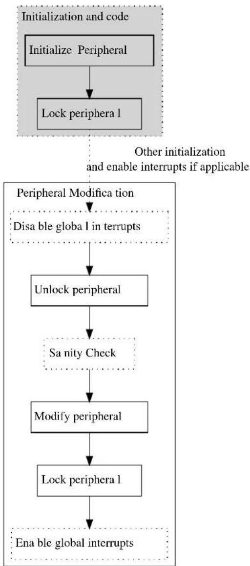
flowchart
graph TD
A["Initialize Peripheral"] --> B["Lock periphera 1"]
B --> C{Peripheral Modification}
C -->|Disable global in interrupts| D["Unlock peripheral"]
D --> E["Sanity Check"]
E --> F["Modify peripheral"]
F --> G["Lock periphera 1"]
G --> H["Ena ble global interrupts"]
I["Initialization and code"] --> A
J["Other initialization and enable interrupts if applicable"] --> C
10.2.3 Why Disable Interrupts
Global interrupts must be disabled while a peripheral is unlocked as an interrupt handler would not know the current state of the peripheral lock. If the interrupt tries to alter the lock state, it can cause an exception as it potentially tries to unlock an already unlocked peripheral. Reading current lock state is to be avoided as it removes the security provided by the PAC (Reading Lock State).
Note
Global interrupts should also be disabled when a peripheral is unlocked inside an interrupt handler.
An example to illustrate the potential hazard of not disabling interrupts is shown in Figure 10-2: Why Disable Interrupts on page 247.
Figure 10-2. Why Disable Interrupts

flowchart
graph TD
A["Initia lize and lock peripherals"] -->|User code| B["Unlock periphera 1"]
B --> C["Modify peripheral"]
C --> D["Lock peripheral Unlock peripheral"]
D -->|Interrupt| E["Interrupt handler"]
E --> F["Modify peripheral NMI"]
F --> G["Lock peripheral"]
G --> H["Red Box"]
style A fill:#f9f,stroke:#333
style H fill:#f9f,stroke:#333
10.2.4 Run-away Code
Run-away code can be caused by the MCU being operated outside its specification, faulty code or EMI issues. If a run-away code occurs, it is favorable to catch the issue as soon as possible. With a correct implementation of the PAC, the run-away code can potentially be stopped.
A graphical example showing how a PAC implementation will behave for different circumstances of run-away code in shown in Figure 10-3: Run-away Code on page 248 and Figure 10-4: Run-away Code on page 249.
Figure 10-3. Run-away Code
- Run-away code is caught in sanity check. A NMI is executed.
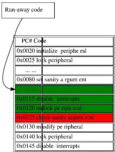
text_image
Run-away code PC# Code 0x0020 initialize periphe ral 0x0025 lock peripheral ... ... 0x0080 set sanity a rgum ent ... ... 0x0115 disable interrupts 0x0120 unlock pe riph eral 0x0125 check sanity argum e nt 0x0130 m modify pe ripheral 0x0140 lock peripheral 0x0145 disable interrupts- Run-away code is caught when modifying locked peripheral. A N MI is executed.
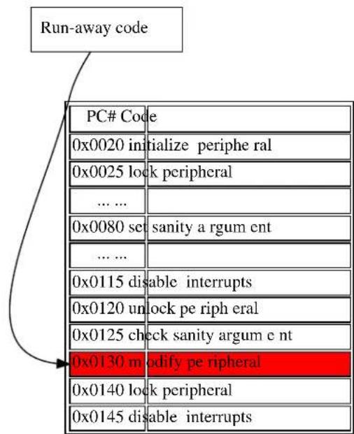
text_image
Run-away code PC# Code 0x0020 initialize periphe ral 0x0025 lock peripheral ... ... 0x0080 set sanity a rgum ent ... ... 0x0115 disable interrupts 0x0120 unlock pe riph eral 0x0125 check sanity argum e nt 0x0130 m modify peripheral 0x0140 lock peripheral 0x0145 disable interruptsFigure 10-4. Run-away Code
-
Run-away code is caught when locking locked peripheral. A NMI is executed.
-
Run-away code is not ca ught.

flowchart
graph TD
A["Run-away code"] --> B["PC# Code"]
B --> C["0x0020 initialize periphera 1"]
B --> D["0x0025 lock periphera 1"]
B --> E["... ..."]
B --> F["0x0080 set sanity argum ent"]
B --> G["... ..."]
B --> H["0x0115 disable inter rupts"]
B --> I["0x0120 unlock peripheral"]
B --> J["0x0125 check sanity a rgum ent"]
B --> K["0x0130 modify peripheral"]
B --> L["0x0140 lock periphera 1"]
B --> M["0x0145 disable inter rupts"]

text_image
Run-away code PC# Code 0x0020 initialize pe riphera 1 0x0025 lock periphera 1 ... ... 0x0080 set sanity argum e nt ... ... 0x0115 disable inter rupts 0x0120 unlock peripheral 0x0125 check sanity a rgum ent 0x0130 m modify peripheral 0x0140 lock periphera 1 0x0145 disable inter ruptsIn the example, green indicates that the command is allowed, red indicates where the run-away code will be caught, and the arrow where the run-away code enters the application. In special circumstances, like example 4 above, the run-away code will not be caught. However, the protection scheme will greatly enhance peripheral configuration security from being affected by run-away code.
10.2.4.1 Key-Argument
To protect the module functions against run-away code themselves, a key is required as one of the input arguments. The key-argument will make sure that run-away code entering the function without a function call will be rejected before inflicting any damage. The argument is simply set to be the bitwise inverse of the module flag, i.e.
system_peripheral_<lock_state>(SYSTEM_PERIPHERAL_<module>, ~SYSTEM_PERIPHERAL_<module>);
Where the lock state can be either lock or unlock, and module refer to the peripheral that is to be locked/unlocked.
10.2.5 Faulty Module Pointer
The PAC also protects the application from user errors such as the use of incorrect module pointers in function arguments, given that the module is locked. It is therefore recommended that any unused peripheral is locked during application initialization.
10.2.6 Use of \_\_no\_inline
Using the function attribute __no_inline will ensure that there will only be one copy of each functions in the PAC driver API in the application. This will lower the likelihood that run-away code will hit any of these functions.
10.2.7 Physical Connection
Figure 10-5: Physical Connection on page 250 shows how this module is interconnected within the device.
Figure 10-5. Physical Connection

flowchart
graph TD
A["Periphe ra 1 bus"] -->|Read/Write| B["Lock"]
A -->|Read/Write| C["Open"]
A -->|Read/Write| D["Open"]
B <-->|Read| E["Periphe ra 11"]
C <-->|Read/Write| F["Periphe ra 12"]
D <-->|Read/Write| G["Periphe ra 13"]
10.3 Special Considerations
10.3.1 Non-Writable Registers
Not all registers in a given peripheral can be set non-writable. Which registers this applies to is showed in List of Non-Write Protected Registers and the peripheral's subsection "Register Access Protection" in the device datasheet.
10.3.2 Reading Lock State
Reading the state of the peripheral lock is to be avoided as it greatly compromises the protection initially provided by the PAC. If a lock/unlock is implemented conditionally, there is a risk that eventual errors are not caught in the protection scheme. Examples indicating the issue are shown in Figure 10-6: Reading Lock State on page 250.
Figure 10-6. Reading Lock State
text_image
Run-away code with periphera 1 unlocked PC# Code ... ... 0x0100 check if locked 0x0102 disable interrupts 0x0105 unlock if locked 0x0110 check sanity 0x0115 m modify periphera 1 0x0120 lock if previously locked 0x0125 enable interrupts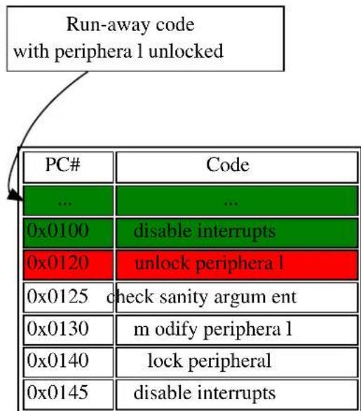
text_image
Run-away code with periphera 1 unlocked PC# Code ... ... 0x0100期間 Tunisia interrupts 0x0120期間 Tunisia unlock periphera 1 0x0125期間 check sanity argum ent 0x0130期間 m odify periphera 1 0x0140期間 lock peripheral 0x0145期間 disable interruptsIn the left figure above, one can see the run-away code continues as all illegal operations are conditional. On the right side figure, the run-away code is caught as it tries to unlock the peripheral.
10.4 Extra Information
For extra information see Extra Information for PAC Driver. This includes:
- Acronyms
- Dependencies
- Errata
- Module History
10.5 Examples
For a list of examples related to this driver, see Examples for PAC Driver.
10.6 API Overview
10.6.1 Macro Definitions
10.6.1.1 Macro SYSTEM_PERIPHERAL_ID
#define SYSTEM_PERIPHERAL_ID(peripheral) \
ID_##peripheral
Retrieves the ID of a specified peripheral name, giving its peripheral bus location.
Table 10-1. Parameters
| Data direction Parameter name Description | |
| [in] peripheral Name of the peripheral instance |
Returns
Bus ID of the specified peripheral instance.
10.6.2 Function Definitions
10.6.2.1 Peripheral lock and unlock
Function system\_peripheral\_lock()
Lock a given peripheral's control registers.
_no_inline enum status_code system_peripheral_lock(
const uint32_t peripheral_id,
const uint32_t key)
Locks a given peripheral's control registers, to deny write access to the peripheral to prevent accidental changes to the module's configuration.
Warning
Locking an already locked peripheral will cause a hard fault exception, and terminate program execution.
Table 10-2. Parameters
| Data direction Parameter name Description | |
| [in] peripheral_id ID for the peripheral to be | locked, sourced via the SYSTEM_PERIPHERAL_ID macro. |
| [in] key Bitwise inverse of peripheral ID, | used as key to reduce the chance of accidental locking. See Key-Argument. |
Returns
Status of the peripheral lock procedure.
Table 10-3. Return Values
| Return value Description | |
| STATUS_OK If the peripheral was successfully locked. | |
| STATUS_ERR_INVALID_ARG If invalid argument(s) were supplied. | |
Function system\_peripheral\_unlock()
Unlock a given peripheral's control registers.
_no_inline enum status_code system_peripheral_unlock(
const uint32_t peripheral_id,
const uint32_t key)
Unlocks a given peripheral's control registers, allowing write access to the peripheral so that changes can be made to the module's configuration.
Warning
Unlocking an already locked peripheral will cause a hard fault exception, and terminate program execution.
Table 10-4. Parameters
| Data direction Parameter name Description | |
| [in] peripheral_id ID for the peripheral to be | unlocked, sourced via the SYSTEM_PERIPHERAL_ID macro. |
| [in] key Bitwise inverse of peripheral ID, | used as key to reduce the chance of accidental unlocking. See Key-Argument. |
Returns
Status of the peripheral unlock procedure.
Table 10-5. Return Values
| Return value Description | |
| STATUS_OK If the peripheral was successfully locked. | |
| STATUS_ERR_INVALID_ARG If invalid argument(s) were supplied. | |
10.7 List of Non-Write Protected Registers
Look in device datasheet peripheral's subsection "Register Access Protection" to see which is actually available for your device.
| Module Non-write protected register | |
| AC INTFLAG | |
| STATUS | |
| STATUSB | |
| STATUSC | |
| ADC INTFLAG | |
| STATUS | |
| RESULT | |
| EVSYS INTFLAG | |
| CHSTATUS | |
| NVMCTRL INTFLAG | |
| STATUS | |
| PM INTFLAG | |
| PORT N/A | |
| RTC INTFLAG | |
| READREQ | |
| STATUS | |
| SYSCTRL INTFLAG | |
| SERCOM INTFALG | |
| STATUS | |
| DATA | |
| TC | INTFLAG |
| STATUS | |
| WDT | INTFLAG |
| STATUS | |
| (CLEAR) |
10.8 Extra Information for PAC Driver
10.8.1 Acronyms
Below is a table listing the acronyms used in this module, along with their intended meanings.
| Acronym Description | |
| AC Analog Comparator | |
| ADC Analog-to-Digital Converter | |
| EVSYS Event System | |
| NMI Non-Maskable Interrupt | |
| NVMCTRL Non-Volatile Memory Controller | |
| PAC Peripheral Access Controller | |
| PM Power Manager | |
| RTC Real-Time Counter | |
| SERCOM Serial Communication Interface | |
| SYSCTRL System Controller | |
| TC Timer/Counter | |
| WDT | Watch Dog Timer |
10.8.2 Dependencies
This driver has the following dependencies:
None
10.8.3 Errata
There are no errata related to this driver.
10.8.4 Module History
An overview of the module history is presented in the table below, with details on the enhancements and fixes made to the module since its first release. The current version of this corresponds to the newest version in the table.
| Changelog |
| Added support for SAMD21 |
| Initial Release |
10.9 Examples for PAC Driver
This is a list of the available Quick Start guides (QSGs) and example applications for SAM D20/D21 Peripheral Access Controller Driver (PAC). QSGs are simple examples with step-by-step instructions to configure and use this driver in a selection of use cases. Note that QSGs can be compiled as a standalone application or be added to the user application.
• Quick Start Guide for PAC - Basic
10.9.1 Quick Start Guide for PAC - Basic
In this use case, the peripheral-lock will be used to lock and unlock the PORT peripheral access, and show how to implement the PAC module when the PORT registers needs to be altered. The PORT will be set up as follows:
• One pin in input mode, with pull-up and falling edge-detect.
• One pin in output mode.
10.9.1.1 Setup
Prerequisites
There are no special setup requirements for this use-case.
Code
Copy-paste the following setup code to your user application:
void config_port_pins(void)
{
struct port_config pin_conf;
port_get_config_defaults(&pin_conf);
pin_conf.direction = PORT_PIN_DIR_INPUT;
pin_conf.input_pull = PORT_PIN_PULL_UP;
port_pin_set_config(BUTTON_0_PIN, &pin_conf);
pin_conf.direction = PORT_PIN_DIR_OUTPUT;
port_pin_set_config(LED_0_PIN, &pin_conf);
}
Add to user application initialization (typically the start of main()):
config_port_pins();
10.9.1.2 Use Case
Code
Copy-paste the following code to your user application:
system_init();
config_port_pins();
system_peripheral_lock(SYSTEM_PERIPHERAL_ID(PORT), ~SYSTEM_PERIPHERAL_ID(PORT));
system_interrupt_enable_global();
while (port_pin_get_input_level(BUTTON_0_PIN)) { /* Wait for button press */ }
system_interrupt_enter_critical_section();
system_peripheral_unlock(SYSTEM_PERIPHERAL_ID(PORT), ~SYSTEM_PERIPHERAL_ID(PORT));
port_pin_toggle_output_level(LED_0_PIN);
system_peripheral_lock(SYSTEM_PERIPHERAL_ID(PORT), ~SYSTEM_PERIPHERAL_ID(PORT));
system_interrupt_leave_critical_section();
while (1) {
/* Do nothing */
Workflow
- Configure some GPIO port pins for input and output.
config_port_pins();
- Lock peripheral access for the PORT module; attempting to update the module while it is in a protected state will cause a Hard Fault exception.
system_peripheral_lock(SYSTEM_PERIPHERAL_ID(PORT), ~SYSTEM_PERIPHERAL_ID(PORT));
- Enable global interrupts.
system_interrupt_enable_global();
- Loop to wait for a button press before continuing.
while (port_pin_get_input_level(BUTTON_0_PIN)) {
/* Wait for button press */
}
- Enter a critical section, so that the PAC module can be unlocked safely and the peripheral manipulated without the possibility of an interrupt modifying the protected module's state.
system_interrupt_enter_critical_section();
- Unlock the PORT peripheral registers.
system_peripheral_unlock(SYSTEM_PERIPHERAL_ID(PORT), ~SYSTEM_PERIPHERAL_ID(PORT));
- Toggle pin 11, and clear edge detect flag.
port_pin_toggle_output_level(LED_0_PIN);
- Lock the PORT peripheral registers.
system_peripheral_lock(SYSTEM_PERIPHERAL_ID(PORT), ~SYSTEM_PERIPHERAL_ID(PORT));
- Exit the critical section to allow interrupts to function normally again.
system_interrupt_leave_critical_section();
- Enter an infinite while loop once the module state has been modified successfully.
while (1) {
/* Do nothing */
}
11. SAM D20/D21 Port Driver (PORT)
This driver for SAM D20/D21 devices provides an interface for the configuration and management of the device's General Purpose Input/Output (GPIO) pin functionality, for manual pin state reading and writing.
The following peripherals are used by this module:
- PORT (GPIO Management)
The outline of this documentation is as follows: - Prerequisites
- Module Overview
• Special Considerations - Extra Information
- Examples
- API Overview
11.1 Prerequisites
There are no prerequisites for this module.
11.2 Module Overview
The device GPIO (PORT) module provides an interface between the user application logic and external hardware peripherals, when general pin state manipulation is required. This driver provides an easy-to-use interface to the physical pin input samplers and output drivers, so that pins can be read from or written to for general purpose external hardware control.
11.2.1 Physical and Logical GPIO Pins
SAM D20/D21 devices use two naming conventions for the I/O pins in the device; one physical, and one logical. Each physical pin on a device package is assigned both a physical port and pin identifier (e.g. "PORTA.0") as well as a monotonically incrementing logical GPIO number (e.g. "GPIO0"). While the former is used to map physical pins to their physical internal device module counterparts, for simplicity the design of this driver uses the logical GPIO numbers instead.
11.2.2 Physical Connection
Figure 11-1: Physical Connection on page 259 shows how this module is interconnected within the device.
Figure 11-1. Physical Connection
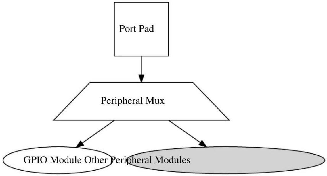
flowchart
graph TD
A["Port Pad"] --> B["Peripheral Mux"]
B --> C["GPIO Module Other Peripheral Modules"]
11.3 Special Considerations
The SAM D20/D21 port pin input sampler can be disabled when the pin is configured in pure output mode to save power; reading the pin state of a pin configured in output-only mode will read the logical output state that was last set.
11.4 Extra Information
For extra information see Extra Information for PORT Driver. This includes:
• Acronyms
- Dependencies
- Errata
- Module History
11.5 Examples
For a list of examples related to this driver, see Examples for PORT Driver.
11.6 API Overview
11.6.1 Structure Definitions
11.6.1.1 Struct port_config
Configuration structure for a port pin instance. This structure should be initialized by the port_get_config_defaults() function before being modified by the user application.
Table 11-1. Members
| Type Name Description | ||
| enum port_pin_dir direction | Port buffer input/output direction. | |
| enum port_pin_pull input_pull Port pull-up/pull-down for input | pins. | |
| bool powersave Enable lowest possible powerstate | on the pin ^1 | |
Notes: ^1 All other configurations will be ignored, the pin will be disabled
11.6.2 Macro Definitions
11.6.2.1 PORT Alias Macros
Macro PORTA
#define PORTA PORT->Group[0]
Convenience definition for GPIO module group A on the device (if available).
Macro PORTB
#define PORTB PORT->Group[1]
Convenience definition for GPIO module group B on the device (if available).
Macro PORTC
#define PORTC PORT->Group[2]
Convenience definition for GPIO module group C on the device (if available).
Macro PORTD
#define PORTD PORT->Group[3]
Convenience definition for GPIO module group D on the device (if available).
11.6.3 Function Definitions
11.6.3.1 State reading/writing (physical group orientated)
Function port\_get\_group\_from\_gpio\_pin()
Retrieves the PORT module group instance from a given GPIO pin number.
PortGroup * port_get_group_from_gpio_pin(const uint8_t gpio_pin)
Retrieves the PORT module group instance associated with a given logical GPIO pin number.
Table 11-2. Parameters
| Data direction Parameter name Description | |
| [in] gpio_pin Index of the GPIO pin to convert. |
Returns
Base address of the associated PORT module.
Function port\_group\_get\_input\_level()
Retrieves the state of a group of port pins that are configured as inputs.
uint32_t port_group_get_input_level( const PortGroup *const port, const uint32_t mask)
Reads the current logic level of a port module's pins and returns the current levels as a bitmask.
Table 11-3. Parameters
| Data direction Parameter name Description | |
| [in] port Base of the PORT module to read | from. |
| [in] mask Mask of the port pin(s) to read. |
Returns
Status of the port pin(s) input buffers.
Function port\_group\_get\_output\_level()
Retrieves the state of a group of port pins that are configured as outputs.
uint32_t port_group_get_output_level( const PortGroup *const port, const uint32_t mask)
Reads the current logical output level of a port module's pins and returns the current levels as a bitmask.
Table 11-4. Parameters
| Data direction Parameter name Description | |
| [in] port Base of the PORT module to read | from. |
| [in] mask Mask of the port pin(s) to read. |
Returns
Status of the port pin(s) output buffers.
Function port\_group\_set\_output\_level()
Sets the state of a group of port pins that are configured as outputs.
void port_group_set_output_level(
PortGroup *const port,
const uint32_t mask,
const uint32_t level_mask)
Sets the current output level of a port module's pins to a given logic level.
Table 11-5. Parameters
| Data direction Parameter name Description | |
| [out] port Base of the PORT module to write | to. |
| [in] mask Mask of the port pin(s) to change. | |
| [in] level_mask Mask of the port level(s) to set. |
Function port\_group\_toggle\_output\_level()
Toggles the state of a group of port pins that are configured as an outputs.
void port_group_toggle_output_level(
PortGroup *const port,
const uint32_t mask)
Toggles the current output levels of a port module's pins.
Table 11-6. Parameters
| Data direction Parameter name Description | |
| [out] port Base of the PORT module to write | to. |
| [in] mask Mask of the port pin(s) to toggle. |
11.6.3.2 Configuration and initialization
Function port\_get\_config\_defaults()
Initializes a Port pin/group configuration structure to defaults.
void port_get_config_defaults(
struct port_config *const config)
Initializes a given Port pin/group configuration structure to a set of known default values. This function should be called on all new instances of these configuration structures before being modified by the user application.
The default configuration is as follows:
- Input mode with internal pullup enabled
Table 11-7. Parameters
| Data direction Parameter name Description | |
| [out] config Configuration structure to initialize | to default values. |
Function port\_pin\_set\_config()
Writes a Port pin configuration to the hardware module.
void port_pin_set_config(
const uint8_t gpio_pin,
const struct port_config *const config)
Writes out a given configuration of a Port pin configuration to the hardware module.
Note
If the pin direction is set as an output, the pull-up/pull-down input configuration setting is ignored.
Table 11-8. Parameters
| Data direction Parameter name Description | |
| [in] gpio_pin Index of the GPIO pin to configure. | |
| [in] config Configuration settings for the pin. |
Function port\_group\_set\_config()
Writes a Port group configuration group to the hardware module.
void port_group_set_config(
PortGroup *const port,
const uint32_t mask,
const struct port_config *const config)
Writes out a given configuration of a Port group configuration to the hardware module.
Note
If the pin direction is set as an output, the pull-up/pull-down input configuration setting is ignored.
Table 11-9. Parameters
| Data direction Parameter name Description | |
| [out] port Base of the PORT module to write | to. |
| [in] mask Mask of the port pin(s) to | configure. |
| [in] config Configuration settings for the pin | group. |
11.6.3.3 State reading/writing (logical pin orientated)
Function port\_pin\_get\_input\_level()
Retrieves the state of a port pin that is configured as an input.
bool port_pin_get_input_level(const uint8_t gpio_pin)
Reads the current logic level of a port pin and returns the current level as a boolean value.
Table 11-10. Parameters
| Data direction Parameter name Description | |
| [in] gpio_pin Index of the GPIO pin to read. |
Returns
Status of the port pin's input buffer.
Function port\_pin\_get\_output\_level()
Retrieves the state of a port pin that is configured as an output.
bool port_pin_get_output_level(const uint8_t gpio_pin)
Reads the current logical output level of a port pin and returns the current level as a boolean value.
Table 11-11. Parameters
| Data direction Parameter name Description | |
| [in] gpio_pin Index of the GPIO pin to read. |
Returns
Status of the port pin's output buffer.
Function port\_pin\_set\_output\_level()
Sets the state of a port pin that is configured as an output.
void port_pin_set_output_level(
const uint8_t gpio_pin,
const bool level)
Sets the current output level of a port pin to a given logic level.
Table 11-12. Parameters
| Data direction Parameter name Description | |
| [in] gpio_pin Index of the GPIO pin to write to. | |
| [in] level Logical level to set the given pin to. |
Function port\_pin\_toggle\_output\_level()
Toggles the state of a port pin that is configured as an output.
void port_pin_toggle_output_level(const uint8_t gpio_pin)
Toggles the current output level of a port pin.
Table 11-13. Parameters
| Data direction Parameter name Description | |
| [in] gpio_pin Index of the GPIO pin to toggle. |
11.6.4 Enumeration Definitions
11.6.4.1 Enum port\_pin\_dir
Enum for the possible pin direction settings of the port pin configuration structure, to indicate the direction the pin should use.
Table 11-14. Members
| Enum value Description | |
| PORT_PIN_DIR_INPUT The pin's input buffer should be enabled, so that the pin state can be read. | |
| PORT_PIN_DIR_OUTPUT The pin's output buffer should be enabled, so that the pin state can be set. | |
| PORT_PIN_DIR_OUTPUT_WTH_READBACK The pin's output and input buffers should be enabled, so that the pin state can be set and read back. | |
11.6.4.2 Enum port\_pin\_pull
Enum for the possible pin pull settings of the port pin configuration structure, to indicate the type of logic level pull the pin should use.
Table 11-15. Members
| Enum value Description | |
| PORT_PIN_PULL_NONE No logical pull should be applied to the pin. | |
| PORT_PIN_PULL_UP Pin should be pulled up when idle. | |
| PORT_PIN_PULL_DOWN Pin should be pulled down when idle. | |
11.7 Extra Information for PORT Driver
11.7.1 Acronyms
Below is a table listing the acronyms used in this module, along with their intended meanings.
| Acronym | Description |
| GPIO | General Purpose Input/Output |
| MUX | Multiplexer |
11.7.2 Dependencies
This driver has the following dependencies:
• System Pin Multiplexer Driver
11.7.3 Errata
There are no errata related to this driver.
11.7.4 Module History
An overview of the module history is presented in the table below, with details on the enhancements and fixes made to the module since its first release. The current version of this corresponds to the newest version in the table.
Changelog
Added support for SAMD21
Initial Release
11.8 Examples for PORT Driver
This is a list of the available Quick Start guides (QSGs) and example applications for SAM D20/D21 Port Driver (PORT). QSGs are simple examples with step-by-step instructions to configure and use this driver in a selection of use cases. Note that QSGs can be compiled as a standalone application or be added to the user application.
- Quick Start Guide for PORT - Basic
11.8.1 Quick Start Guide for PORT - Basic
In this use case, the PORT module is configured for:
• One pin in input mode, with pull-up enabled
• One pin in output mode
This use case sets up the PORT to read the current state of a GPIO pin set as an input, and mirrors the opposite logical state on a pin configured as an output.
11.8.1.1 Setup
Prerequisites
There are no special setup requirements for this use-case.
Code
Copy-paste the following setup code to your user application:
void configure_port_pins(void)
{
struct port_config config_port_pin;
port_get_config_defaults(&config_port_pin);
config_port_pin.direction = PORT_PIN_DIR_INPUT;
config_port_pin.input_pull = PORT_PIN_PULL_UP;
port_pin_set_config(BUTTON_0_PIN, &config_port_pin);
config_port_pin.direction = PORT_PIN_DIR_OUTPUT;
port_pin_set_config(LED_0_PIN, &config_port_pin);
}
Add to user application initialization (typically the start of main()):
configure_port_pins();
Workflow
- Create a PORT module pin configuration struct, which can be filled out to adjust the configuration of a single port pin.
struct port_config config_port_pin;
- Initialize the pin configuration struct with the module's default values.
port_get_config_defaults(&config_port_pin);
Note
This should always be performed before using the configuration struct to ensure that all values are initialized to known default settings.
- Adjust the configuration struct to request an input pin.
config_port_pin.direction = PORT_PIN_DIR_INPUT;
config_port_pin.input_pull = PORT_PIN_PULL_UP;
- Configure push button pin with the initialized pin configuration struct, to enable the input sampler on the pin.
port_pin_set_config(BUTTON_0_PIN, &config_port_pin);
- Adjust the configuration struct to request an output pin.
config_port_pin.direction = PORT_PIN_DIR_OUTPUT;
Note
The existing configuration struct may be re-used, as long as any values that have been altered from the default settings are taken into account by the user application.
- Configure LED pin with the initialized pin configuration struct, to enable the output driver on the pin.
port_pin_set_config(LED_0_PIN, &config_port_pin);
11.8.1.2 Use Case
Code
Copy-paste the following code to your user application:
while (true) {
bool pin_state = port_pin_get_input_level(BUTTON_0_PIN);
port_pin_set_output_level(LED_0_PIN, !pin_state);
}
Workflow
- Read in the current input sampler state of push button pin, which has been configured as an input in the use-case setup code.
bool pin_state = port_pin_get_input_level(BUTTON_0_PIN);
- Write the inverted pin level state to LED pin, which has been configured as an output in the use-case setup code.
port_pin_set_output_level(LED_0_PIN, !pin_state);
12. SAM D20/D21 RTC Calendar Driver (RTC CAL)
This driver for SAM D20/D21 devices provides an interface for the configuration and management of the device's Real Time Clock functionality in Calendar operating mode, for the configuration and retrieval of the current time and date as maintained by the RTC module. The following driver API modes are covered by this manual:
- Polled APIs
- Callback APIs
The following peripherals are used by this module:
• RTC (Real Time Clock)
The outline of this documentation is as follows:
- Prerequisites
- Module Overview
• Special Considerations - Extra Information
- Examples
- API Overview
12.1 Prerequisites
There are no prerequisites for this module.
12.2 Module Overview
The RTC module in the SAM D20/D21 devices is a 32-bit counter, with a 10-bit programmable prescaler. Typically, the RTC clock is run continuously, including in the device's low-power sleep modes, to track the current time and date information. The RTC can be used as a source to wake up the system at a scheduled time or periodically using the alarm functions.
In this driver, the RTC is operated in Calendar mode. This allows for an easy integration of a real time clock and calendar into a user application to track the passing of time and/or perform scheduled tasks.
Whilst operating in Calendar mode, the RTC features:
• Time tracking in seconds, minutes and hours
• 12 hour or 24 hour mode
• Date tracking in day, month and year
• Automatic leap year correction
12.2.1 Alarms and Overflow
The RTC has 4 independent hardware alarms that can be configured by the user application. These alarms will be will triggered on match with the current clock value, and can be set up to trigger an interrupt, event, or both. The RTC can also be configured to clear the clock value on alarm match, resetting the clock to the original start time.
If the RTC is operated in clock-only mode (i.e. with calendar disabled), the RTC counter value will instead be cleared on overflow once the maximum count value has been reached:
$$ C O U N T _ {M A X} = 2 ^ {3 2} - 1 \tag {12.1} $$
When the RTC is operated with the calendar enabled and run using a nominal 1 Hz input clock frequency, a register overflow will occur after 64 years.
12.2.2 Periodic Events
The RTC can generate events at periodic intervals, allowing for direct peripheral actions without CPU intervention. The periodic events can be generated on the upper 8 bits of the RTC prescaler, and will be generated on the rising edge transition of the specified bit. The resulting periodic frequency can be calculated by the following formula:
$$ f _ {P E R I O D I C} = \frac {f _ {A S Y}}{2 ^ {n + 3}} \tag {12.2} $$
Where
$$ f _ {A S Y} \tag {12.3} $$
refers to the asynchronous clock set up in the RTC module configuration. For the RTC to operate correctly in calendar mode, this frequency must be 1KHz, while the RTC's internal prescaler should be set to divide by 1024. The n parameter is the event source generator index of the RTC module. If the asynchronous clock is operated at the recommended 1KHz, the formula results in the values shown in Table 12-1: RTC event frequencies for each prescaler bit using a 1KHz clock on page 270.
Table 12-1. RTC event frequencies for each prescaler bit using a 1KHz clock
| n Periodic event | |
| 7 1 Hz | |
| 6 2 Hz | |
| 5 4 Hz | |
| 4 8 Hz | |
| 3 16 Hz | |
| 2 32 Hz | |
| 1 64 Hz | |
| 0 128 Hz |
Note
The connection of events between modules requires the use of the SAM D20/D21 Event System Driver (EVENTS) to route output event of one module to the input event of another. For more information on event routing, refer to the event driver documentation.
12.2.3 Digital Frequency Correction
The RTC module contains Digital Frequency Correction logic to compensate for inaccurate source clock frequencies which would otherwise result in skewed time measurements. The correction scheme requires that at least two bits in the RTC module prescaler are reserved by the correction logic. As a result of this implementation, frequency correction is only available when the RTC is running from a 1 Hz reference clock.
The correction procedure is implemented by subtracting or adding a single cycle from the RTC prescaler every 1024 RTC GCLK cycles. The adjustment is applied the specified number of time (max 127) over 976 of these periods. The corresponding correction in PPM will be given by:
$$ \text { Correction } (P P M) = \frac {\text { VALUE }}{9 9 9 4 2 4} 1 0 ^ {6} \tag {12.4} $$
The RTC clock will tick faster if provided with a positive correction value, and slower when given a negative correction value.
12.3 Special Considerations
12.3.1 Year limit
The RTC module has a year range of 63 years from the starting year configured when the module is initialized. Dates outside the start to end year range described below will need software adjustment:
$$ \left[ Y E A R _ {S T A R T}, Y E A R _ {S T A R T} + 6 4\right) \tag {12.5} $$
12.3.2 Clock Setup
The RTC is typically clocked by a specialized GCLK generator that has a smaller prescaler than the others. By default the RTC clock is on, selected to use the internal 32 kHz RC-oscillator with a prescaler of 32, giving a resulting clock frequency of 1024 Hz to the RTC. When the internal RTC prescaler is set to 1024, this yields an end-frequency of 1Hz for correct time keeping operations.
The implementer also has the option to set other end-frequencies. Table 12-2: RTC output frequencies from allowable input clocks on page 271 lists the available RTC frequencies for each possible GCLK and RTC input prescaler options.
Table 12-2. RTC output frequencies from allowable input clocks
| End-frequency GCLK prescaler RTC Prescaler | |
| 32 KHz 1 1 | |
| 1 KHz 32 1 | |
| 1 Hz 32 1024 |
The overall RTC module clocking scheme is shown in Figure 12-1: Clock Setup on page 271.
Figure 12-1. Clock Setup
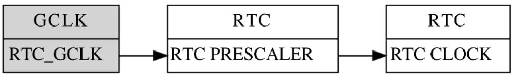
flowchart
graph LR
A["GCLK"] --> B["RTC"]
C["RTC_GCLK"] --> B
B --> D["RTC"]
E["RTC"] --> F["RTC CLOCK"]
B --> G["RTC PRESCALER"]
Note
For the calendar to operate correctly, an asynchronous clock of 1Hz should be used.
12.4 Extra Information
For extra information see Extra Information for RTC (CAL) Driver. This includes:
• Acronyms
- Dependencies
Errata
- Module History
12.5 Examples
For a list of examples related to this driver, see Examples for RTC CAL Driver.
12.6 API Overview
12.6.1 Structure Definitions
12.6.1.1 Struct rtc\_calendar\_alarm\_time
Alarm structure containing time of the alarm and a mask to determine when the alarm will trigger.
Table 12-3. Members
| Type | Name Description | |
| enum rtc_calendar_alarm_mask | mask | Alarm mask to determine on what precision the alarm will match. |
Type Name Description
struct rtc_calendar_time time Alarm time.
12.6.1.2 Struct rtc\_calendar\_config
Configuration structure for the RTC instance. This structure should be initialized using the rtc_calendar_get_config_defaults() before any user configurations are set.
Table 12-4. Members
| Type Name Description | ||
| structrtc_calendar_alarm_time alarm[] Alarm values. | ||
| boolclear_on_match If true, clears the clock on alarm | match. | |
| boolclock_24h If true, time is represented in 24 | hour mode. | |
| boolcontinuously_update If true, the digital counter registers | will be continuously updated so that internal synchronization is not needed when reading the current count. | |
| enumrtc_calendar_prescaler prescaler Input clock prescaler for the RTC | module. | |
| uint16_t year_init_value Initial year for counter value 0. | ||
12.6.1.3 Struct rtc\_calendar\_events
Event flags for the rtc_calendar_enable_events() and rtc_calendar_disable_events().
Table 12-5. Members
| Type Name Description | ||
| bool generate_event_on_alarm[] Generate an output event on a | alarm channel match against the RTC count. | |
| bool generate_event_on_overflow | Generate an output event on each overflow of the RTC count. | |
| bool generate_event_on_periodic[] | Generate an output event | periodically at a binary division of the RTC counter frequency (see Periodic Events). |
12.6.1.4 Struct rtc\_calendar\_time
Time structure containing the time given by or set to the RTC calendar. The structure uses seven values to give second, minute, hour, PM/AM, day, month and year. It should be initialized via the rtc_calendar_get_time_defaults() function before use.
Table 12-6. Members
| Type Name Description | ||
| uint8_t | day | Day value, where day 1 is the first day of the month. |
| uint8_t hour Hour value. | ||
| uint8_t minute Minute value. | ||
| uint8_t month Month value, where month 1 is | January. | |
| bool pm PM/AM value, true for PM, or false | for AM. | |
| uint8_t second Second value. | ||
| uint16_t year Year value. | ||
12.6.2 Function Definitions
12.6.2.1 Configuration and initialization
Function rtc\_calendar\_is\_syncing()
Determines if the hardware module(s) are currently synchronizing to the bus.
bool rtc_calendar_is_syncing(
struct rtc_module *const module)
Checks to see if the underlying hardware peripheral module(s) are currently synchronizing across multiple clock domains to the hardware bus. This function can be used to delay further operations on a module until such time that it is ready, to prevent blocking delays for synchronization in the user application.
Table 12-7. Parameters
| Data direction Parameter name Description | ||
| [in] module | RTC hardware module | |
Returns
Synchronization status of the underlying hardware module(s).
Table 12-8. Return Values
| Return value | Description |
| true | if the module has completed synchronization |
| false | if the module synchronization is ongoing |
Function rtc\_calendar\_get\_time\_defaults()
Initialize a time structure.
void rtc_calendar_get_time_defaults(
struct rtc_calendar_time *const time)
This will initialize a given time structure to the time 00:00:00 (hh:mm:ss) and date 2000-01-01 (YYYY-MM-DD).
Table 12-9. Parameters
| Data direction Parameter name Description | ||
| [out] | time Time structure to initialize. | |
Function rtc\_calendar\_get\_config\_defaults()
Gets the RTC default settings.
void rtc_calendar_get_config_defaults(
struct rtc_calendar_config *const config)
Initializes the configuration structure to the known default values. This function should be called at the start of any RTC initiation.
The default configuration is as follows:
- Input clock divided by a factor of 1024.
• Clear on alarm match off.
• Continuously sync clock off.
• 12 hour calendar. - Start year 2000 (Year 0 in the counter will be year 2000).
- Events off.
• Alarms set to January 1. 2000, 00:00:00. - Alarm will match on second, minute, hour, day, month and year.
Table 12-10. Parameters
| Data direction Parameter name Description | |
| [out] config Configuration structure to be | initialized to default values. |
Function rtc\_calendar\_reset()
Resets the RTC module Resets the RTC module to hardware defaults.
void rtc_calendar_reset(
struct rtc_module *const module)
Table 12-11. Parameters
| Data direction Parameter name Description | |
| [in, out] module Pointer to the software instance | struct |
Function rtc\_calendar\_enable()
Enables the RTC module.
void rtc_calendar_enable(
struct rtc_module *const module)
Enables the RTC module once it has been configured, ready for use. Most module configuration parameters cannot be altered while the module is enabled.
Table 12-12. Parameters
| Data direction Parameter name Description | |
| [in, out] module Pointer to the software instance | struct |
Function rtc\_calendar\_disable()
Disables the RTC module.
void rtc_calendar_disable(
struct rtc_module *const module)
Disables the RTC module.
Table 12-13. Parameters
| Data direction Parameter name Description | |
| [in, out] module Pointer to the software instance | struct |
Function rtc\_calendar\_init()
Initializes the RTC module with given configurations.
void rtc_calendar_init(
struct rtc_module *const module,
Rtc *const hw,
const struct rtc_calendar_config *const config)
Initializes the module, setting up all given configurations to provide the desired functionality of the RTC.
Table 12-14. Parameters
| Data direction Parameter name Description | |
| [out] module Pointer to the software instance | struct |
| [in] hw Pointer to hardware instance | |
| [in] config Pointer to the configuration | structure. |
Function rtc\_calendar\_swap\_time\_mode()
Swaps between 12h and 24h clock mode.
void rtc_calendar_swap_time_mode(
struct rtc_module *const module)
Swaps the current RTC time mode.
- If currently in 12h mode, it will swap to 24h.
- If currently in 24h mode, it will swap to 12h.
Note
This will not change setting in user's configuration structure.
Table 12-15. Parameters
| Data direction Parameter name Description | |
| [in, out] module Pointer to the software instance | struct |
Function rtc\_calendar\_frequency\_correction()
Calibrate for too-slow or too-fast oscillator.
enum status_code rtc_calendar_frequency_correction(
struct rtc_module *const module,
const int8_t value)
When used, the RTC will compensate for an inaccurate oscillator. The RTC module will add or subtract cycles from the RTC prescaler to adjust the frequency in approximately 1 PPM steps. The provided correction value should be between -127 and 127, allowing for a maximum 127 PPM correction in either direction.
If no correction is needed, set value to zero.
Note
Can only be used when the RTC is operated at 1Hz.
Table 12-16. Parameters
| Data direction Parameter name Description | |
| [in, out] module Pointer to the software instance | struct |
| [in] value Between -127 and 127 used for the | correction. |
Returns
Status of the calibration procedure.
Table 12-17. Return Values
| Return value Description | |
| STATUS_OK If calibration was done correctly. | |
| STATUS_ERR_INVALID_ARG If invalid argument(s) were provided. | |
12.6.2.2 Time and alarm management
Function rtc_calendar_set_time()
Set the current calendar time to desired time.
void rtc_calendar_set_time(
struct rtc_module *const module,
const struct rtc_calendar_time *const time)
Sets the time provided to the calendar.
Table 12-18. Parameters
| Data direction Parameter name Description | |
| [in, out] module Pointer to the software instance | struct |
| [in] time The time to set in the calendar. |
Function rtc\_calendar\_get\_time()
Get the current calendar value.
void rtc_calendar_get_time(
struct rtc_module *const module,
struct rtc_calendar_time *const time)
Retrieves the current time of the calendar.
Table 12-19. Parameters
| Data direction Parameter name Description | |
| [in, out] module Pointer to the software instance | struct |
| [out] time Pointer to value that will be filled | with current time. |
Function rtc\_calendar\_set\_alarm()
Set the alarm time for the specified alarm.
enum status_code rtc_calendar_set_alarm(
struct rtc_module *const module,
const struct rtc_calendar_alarm_time *const alarm,
const enum rtc_calendar_alarm alarm_index)
Sets the time and mask specified to the requested alarm.
Table 12-20. Parameters
| Data direction Parameter name Description | |
| [in, out] module Pointer to the software instance | struct |
| [in] alarm The alarm struct to set the alarm | with. |
| [in] alarm_index The index of the alarm to set. |
Returns
Status of setting alarm.
Table 12-21. Return Values
| Return value Description | |
| STATUS_OK If alarm was set correctly. | |
| STATUS_ERR_INVALID_ARG If invalid argument(s) were provided. | |
Function rtc\_calendar\_get\_alarm()
Get the current alarm time of specified alarm.
enum status_code rtc_calendar_get_alarm(
struct rtc_module *const module,
struct rtc_calendar_alarm_time *const alarm,
const enum rtc_calendar_alarm alarm_index)
Retrieves the current alarm time for the alarm specified.
Table 12-22. Parameters
| Data direction Parameter name Description | |
| [in, out] module Pointer to the software instance | struct |
| [out] alarm Pointer to the struct that will be | filled with alarm time and mask of the specified alarm. |
| [in] alarm_index Index of alarm to get alarm time | from. |
Returns
Status of getting alarm.
Table 12-23. Return Values
| Return value Description | |
| STATUS_OK If alarm was read correctly. | |
| STATUS_ERR_INVALID_ARG If invalid argument(s) were provided. | |
12.6.2.3 Status flag management
Function rtc\_calendar\_is\_overflow()
Check if an RTC overflow has occurred.
bool rtc_calendar_is_overflow(
struct rtc_module *const module)
Checks the overflow flag in the RTC. The flag is set when there is an overflow in the clock.
Table 12-24. Parameters
| Data direction Parameter name Description | |
| [in, out] module Pointer to the software instance | struct |
Returns
Overflow state of the RTC module.
Table 12-25. Return Values
| Return value Description | |
| true If the RTC count value has overflowed | |
| false If the RTC count value has not overflowed |
Function rtc\_calendar\_clear\_overflow()
Clears the RTC overflow flag.
void rtc_calendar_clear_overflow(
struct rtc_module *const module)
Table 12-26. Parameters
| Data direction Parameter name Description | |
| [in, out] module Pointer to the software instance | struct |
Clears the RTC module counter overflow flag, so that new overflow conditions can be detected.
Function rtc\_calendar\_is\_alarm\_match()
Check the RTC alarm flag.
bool rtc_calendar_is_alarm_match(
struct rtc_module *const module,
const enum rtc_calendar_alarm alarm_index)
Check if the specified alarm flag is set. The flag is set when there is an compare match between the alarm value and the clock.
Table 12-27. Parameters
| Data direction Parameter name Description | |
| [in, out] module Pointer to the software instance | struct |
| [in] alarm_index Index of the alarm to check. |
Returns
Match status of the specified alarm.
Table 12-28. Return Values
| Return value Description | |
| true If the specified alarm has matched the current time |
Return value Description
false If the specified alarm has not matched the current time
Function rtc\_calendar\_clear\_alarm\_match()
Clears the RTC alarm match flag.
enum status_code rtc_calendar_clear_alarm_match(
struct rtc_module *const module,
const enum rtc_calendar_alarm alarm_index)
Clear the requested alarm match flag, so that future alarm matches can be determined.
Table 12-29. Parameters
| Data direction Parameter name Description | |
| [in, out] module Pointer to the software instance | struct |
| [in] alarm_index The index of the alarm match to | clear. |
Returns
Status of the alarm match clear operation.
Table 12-30. Return Values
| Return value Description | |
| STATUS_OK If flag was cleared correctly. | |
| STATUS_ERR_INVALID_ARG If invalid argument(s) were provided. | |
12.6.2.4 Event management
Function rtc\_calendar\_enable\_events()
Enables a RTC event output.
void rtc_calendar_enable_events(
struct rtc_module *const module,
struct rtc_calendar_events *const events)
Enables one or more output events from the RTC module. See rtc_calendar_events for a list of events this module supports.
Note
Events cannot be altered while the module is enabled.
Table 12-31. Parameters
| Data direction Parameter name Description | |
| [in, out] module Pointer to the software instance | struct |
| [in] events Struct containing flags of events to | enable |
Function rtc\_calendar\_disable\_events()
Disables a RTC event output.
void rtc_calendar_disable_events(
struct rtc_module *const module,
struct rtc_calendar_events *const events)
Disabled one or more output events from the RTC module. See rtc_calendar_events for a list of events this module supports.
Note
Events cannot be altered while the module is enabled.
Table 12-32. Parameters
| Data direction Parameter name Description | |
| [in, out] module Pointer to the software instance | struct |
| [in] events Struct containing flags of events to | disable |
12.6.2.5 Callbacks
Function rtc\_calendar\_register\_callback()
Registers callback for the specified callback type.
enum status_code rtc_calendar_register_callback(
struct rtc_module *const module,
rtc_calendar_callback_t callback,
enum rtc_calendar_callback callback_type)
Associates the given callback function with the specified callback type. To enable the callback, the rtc_calendar_enable_callback function must be used.
Table 12-33. Parameters
| Data direction Parameter name Description | |
| [in, out] module Pointer to the software instance | struct |
| [in] callback Pointer to the function desired for | the specified callback |
| [in] callback_type Callback type to register |
Returns
Status of registering callback
Table 12-34. Return Values
| Return value Description | |
| STATUS_OK Registering was done successfully |
Return value Description
STATUS_ERR_INVALID_ARG If trying to register a callback not available
Function rtc\_calendar\_unregister\_callback()
Unregisters callback for the specified callback type.
enum status_code rtc_calendar_unregister_callback(
struct rtc_module *const module,
enum rtc_calendar_callback callback_type)
When called, the currently registered callback for the given callback type will be removed.
Table 12-35. Parameters
| Data direction Parameter name Description | |
| [in, out] module Pointer to the software instance | struct |
| [in] callback_type Specifies the callback type to | unregister |
Returns
Status of unregistering callback
Table 12-36. Return Values
| Return value Description | |
| STATUS_OK Unregistering was done successfully | |
| STATUS_ERR_INVALID_ARG If trying to unregister a callback not available | |
Function rtc\_calendar\_enable\_callback()
Enables callback.
void rtc_calendar_enable_callback(
struct rtc_module *const module,
enum rtc_calendar_callback callback_type)
Enables the callback specified by the callback_type.
Table 12-37. Parameters
| Data direction Parameter name Description | |
| [in, out] module Pointer to the software instance | struct |
| [in] callback_type Callback type to enable |
Function rtc\_calendar\_disable\_callback()
Disables callback.
void rtc_calendar_disable_callback(
struct rtc_module *const module,
enum rtc_calendar_callback callback_type)
Disables the callback specified by the callback_type.
Table 12-38. Parameters
| Data direction Parameter name Description | |
| [in, out] module Pointer to the software instance | struct |
| [in] callback_type Callback type to disable |
12.6.3 Enumeration Definitions
12.6.3.1 Enum rtc\_calendar\_alarm
Available alarm channels.
Note
Not all alarm channels are available on all devices.
Table 12-39. Members
| Enum value Description | |
| RTC_CALENDAR_ALARM_0 Alarm channel 0. | |
| RTC_CALENDAR_ALARM_1 Alarm channel 1. | |
| RTC_CALENDAR_ALARM_2 Alarm channel 2. | |
| RTC_CALENDAR_ALARM_3 Alarm channel 3. |
12.6.3.2 Enum rtc\_calendar\_alarm\_mask
Available mask options for alarms.
Table 12-40. Members
| Enum value Description | |
| RTC_CALENDAR_ALARM_MASK_DISABLED Alarm disabled | |
| RTC_CALENDAR_ALARM_MASK_SEC Alarm match on second | |
| RTC_CALENDAR_ALARM_MASK_MIN Alarm match on second and minute | |
| RTC_CALENDAR_ALARM_MASK_HOUR Alarm match on second, minute and hour | |
| RTC_CALENDAR_ALARM_MASK_DAY Alarm match on second, minutes hour and day | |
| RTC_CALENDAR_ALARM_MASK_MONTH | Alarm match on second, minute, hour, day and month |
| RTC_CALENDAR_ALARM_MASK_YEAR | Alarm match on second, minute, hour, day, month and year |
12.6.3.3 Enum rtc\_calendar\_callback
The available callback types for the RTC calendar module.
Table 12-41. Members
| Enum value Description | |
| RTC_CALENDAR_CALLBACK_ALARM_0 Callback for alarm 0 | |
| RTC_CALENDAR_CALLBACK_ALARM_1 Callback for alarm 1 | |
| RTC_CALENDAR_CALLBACK_ALARM_2 Callback for alarm 2 | |
| RTC_CALENDAR_CALLBACK_ALARM_3 Callback for alarm 3 | |
| RTC_CALENDAR_CALLBACK_OVERFLOW Callback for overflow |
12.6.3.4 Enum rtc\_calendar\_prescaler
The available input clock prescaler values for the RTC calendar module.
Table 12-42. Members
| Enum value Description | |
| RTC_CALENDAR_PRESCALER_DIV_1 RTC input clock frequency is prescaled by a factor of 1. | |
| RTC_CALENDAR_PRESCALER_DIV_2 RTC input clock frequency is prescaled by a factor of 2. | |
| RTC_CALENDAR_PRESCALER_DIV_4 RTC input clock frequency is prescaled by a factor of 4. | |
| RTC_CALENDAR_PRESCALER_DIV_8 RTC input clock frequency is prescaled by a factor of 8. | |
| RTC_CALENDAR_PRESCALER_DIV_16 RTC input clock frequency is prescaled by a factor of 16. | |
| RTC_CALENDAR_PRESCALER_DIV_32 RTC input clock frequency is prescaled by a factor of 32. | |
| RTC_CALENDAR_PRESCALER_DIV_64 RTC input clock frequency is prescaled by a factor of 64. | |
| RTC_CALENDAR_PRESCALER_DIV_128 RTC input clock frequency is prescaled by a factor of 128. | |
| RTC_CALENDAR_PRESCALER_DIV_256 RTC input clock frequency is prescaled by a factor of 256. | |
| RTC_CALENDAR_PRESCALER_DIV_512 RTC input clock frequency is prescaled by a factor of 512. | |
| RTC_CALENDAR_PRESCALER_DIV_1024 RTC input clock frequency is prescaled by a factor of 1024. | |
12.7 Extra Information for RTC (CAL) Driver
12.7.1 Acronyms
Below is a table listing the acronyms used in this module, along with their intended meanings.
| Acronym Description | |
| RTC Real Time Counter | |
| PPM Part Per Million | |
| RC Resistor/Capacitor |
12.7.2 Dependencies
This driver has the following dependencies:
None
12.7.3 Errata
There are no errata related to this driver.
12.7.4 Module History
An overview of the module history is presented in the table below, with details on the enhancements and fixes made to the module since its first release. The current version of this corresponds to the newest version in the table.
| Changelog |
| Added support for SAMD21 and added driver instance parameter to all API function calls, except get_config_defaults. |
| Updated initialization function to also enable the digital interface clock to the module if it is disabled. |
| Initial Release |
12.8 Examples for RTC CAL Driver
This is a list of the available Quick Start guides (QSGs) and example applications for SAM D20/D21 RTC Calendar Driver (RTC CAL). QSGs are simple examples with step-by-step instructions to configure and use this driver in a selection of use cases. Note that QSGs can be compiled as a standalone application or be added to the user application.
- Quick Start Guide for RTC (CAL) - Basic
- Quick Start Guide for RTC (CAL) - Callback
12.8.1 Quick Start Guide for RTC (CAL) - Basic
In this use case, the RTC is set up in calendar mode. The time is set and also a alarm is set to show a general use of the RTC in calendar mode. Also the clock is swapped from 24h to 12h mode after initialization. The board LED will be toggled once the current time matches the set time.
12.8.1.1 Prerequisites
The Generic Clock Generator for the RTC should be configured and enabled; if you are using the System Clock driver, this may be done via conf_clocks.h.
Clocks and Oscillators
The conf_clock.h file needs to be changed with the following values to configure the clocks and oscillators for the module.
The following oscillator settings are needed:
/* SYSTEM_CLOCK_SOURCE_OSC32K configuration - Internal 32KHz oscillator */
<h1 id="define-conf_clock_osc32k_enable-true">define CONF_CLOCK_OSC32K_ENABLE true</h1>
<h1 id="define-conf_clock_osc32k_startup_time-system_osc32k_startup_130">define CONF_CLOCK_OSC32K_STARTUP_TIME SYSTEM_OSC32K_STARTUP_130</h1>
<h1 id="define-conf_clock_osc32k_enable_1khz_output-true">define CONF_CLOCK_OSC32K_ENABLE_1KHZ_OUTPUT true</h1>
<h1 id="define-conf_clock_osc32k_enable_32khz_output-true">define CONF_CLOCK_OSC32K_ENABLE_32KHZ_OUTPUT true</h1>
<h1 id="define-conf_clock_osc32k_on_demand-true">define CONF_CLOCK_OSC32K_ON_DEMAND true</h1>
<h1 id="define-conf_clock_osc32k_run_in_standby-false">define CONF_CLOCK_OSC32K_RUN_IN_STANDBY false</h1>
The following generic clock settings are needed:
/* Configure GCLK generator 2 (RTC) */
<h1 id="define-conf_clock_gclk_2_enable-true">define CONF_CLOCK_GCLK_2_ENABLE true</h1>
<h1 id="define-conf_clock_gclk_2_run_in_standby-false">define CONF_CLOCK_GCLK_2_RUN_IN_STANDBY false</h1>
<h1 id="define-conf_clock_gclk_2_clock_source-system_clock_source_osc32k">define CONF_CLOCK_GCLK_2_CLOCK_SOURCE SYSTEM_CLOCK_SOURCE_OSC32K</h1>
<h1 id="define-conf_clock_gclk_2_prescaler-32">define CONF_CLOCK_GCLK_2_PRESCALER 32</h1>
<h1 id="define-conf_clock_gclk_2_output_enable-false">define CONF_CLOCK_GCLK_2_OUTPUT_ENABLE false</h1>
12.8.1.2 Setup
Initialization Code
Create a rtc_module struct and add to the main application source file, outside of any functions:
struct rtc_module rtc_instance;
Copy-paste the following setup code to your application:
void configure_rtc_calendar(void)
{
/* Initialize RTC in calendar mode. */
struct rtc_calendar_config config_rtc_calendar;
rtc_calendar_get_config_defaults(&config_rtc_calendar);
struct rtc_calendar_time alarm;
rtc_calendar_get_time_defaults(&alarm);
alarm.year = 2013;
alarm.month = 1;
alarm.day = 1;
alarm.hour = 0;
alarm.minute = 0;
alarm.second = 4;
config_rtc_calendar.clock_24h = true;
config_rtc_calendar.alarm[0].time = alarm;
config_rtc_calendar.alarm[0].mask = RTC_CALENDAR_ALARM_MASK_YEAR;
rtc_calendar_init(&rtc_instance, RTC, &config_rtc_calendar);
rtc_calendar_enable(&rtc_instance);
}
Add to Main
Add the following to main().
system_init();
struct rtc_calendar_time time;
time.year = 2012;
time.month = 12;
time.day = 31;
time.hour = 23;
time.minute = 59;
time.second = 59;
configure_rtc_calendar();
/* Set current time. */
rtc_calendar_set_time(&rtc_instance, &time);
rtc_calendar_swap_time_mode(&rtc_instance);
Workflow
- Make configuration structure.
struct rtc_calendar_config config_rtc_calendar;
- Fill the configuration structure with the default driver configuration.
rtc_calendar_get_config_defaults(&config_rtc_calendar);
Note
This should always be performed before using the configuration struct to ensure that all values are initialized to known default settings.
- Make time structure for alarm and set with default and desired values.
struct rtc_calendar_time alarm;
rtc_calendar_get_time_defaults(&alarm);
alarm.year = 2013;
alarm.month = 1;
alarm.day = 1;
alarm.hour = 0;
alarm.minute = 0;
alarm.second = 4;
- Change configurations as desired.
config_rtc_calendar.clock_24h = true;
config_rtc_calendar.alarm[0].time = alarm;
config_rtc_calendar.alarm[0].mask = RTC_CALENDAR_ALARM_MASK_YEAR;
- Initialize module.
rtc_calendar_init(&rtc_instance, RTC, &config_rtc_calendar);
- Enable module
rtc_calendar_enable(&rtc_instance);
12.8.1.3 Implementation
Add the following to main().
while (true) {
if (rtc_calendar_is_alarm_match(&rtc_instance, RTC_CALENDAR_ALARM_0)) {
/* Do something on RTC alarm match here */
port_pin_toggle_output_level(LED_0_PIN);
rtc_calendar_clear_alarm_match(&rtc_instance, RTC_CALENDAR_ALARM_0);
}
Workflow
- Start an infinite loop, to continuously poll for a RTC alarm match.
while (true) {
- Check to see if a RTC alarm match has occurred.
if (rtc_calendar_is_alarm_match(&rtc_instance, RTC_CALENDAR_ALARM_0)) {
- Once an alarm match occurs, perform the desired user action.
/* Do something on RTC alarm match here */
port_pin_toggle_output_level(LED_0_PIN);
- Clear the alarm match, so that future alarms may occur.
rtc_calendar_clear_alarm_match(&rtc_instance, RTC_CALENDAR_ALARM_0);
12.8.2 Quick Start Guide for RTC (CAL) - Callback
In this use case, the RTC is set up in calendar mode. The time is set and an alarm is enabled, as well as a callback for when the alarm time is hit. Each time the callback fires, the alarm time is reset to 5 seconds in the future and the board LED toggled.
12.8.2.1 Prerequisites
The Generic Clock Generator for the RTC should be configured and enabled; if you are using the System Clock driver, this may be done via conf_clocks.h.
Clocks and Oscillators
The conf_clock.h file needs to be changed with the following values to configure the clocks and oscillators for the module.
The following oscillator settings are needed:
/* SYSTEM_CLOCK_SOURCE_OSC32K configuration - Internal 32KHz oscillator */
<h1 id="define-conf_clock_osc32k_enable-true-2">define CONF_CLOCK_OSC32K_ENABLE true</h1>
<h1 id="define-conf_clock_osc32k_startup_time-system_osc32k_startup_130-2">define CONF_CLOCK_OSC32K_STARTUP_TIME SYSTEM_OSC32K_STARTUP_130</h1>
<h1 id="define-conf_clock_osc32k_enable_1khz_output-true-2">define CONF_CLOCK_OSC32K_ENABLE_1KHZ_OUTPUT true</h1>
<h1 id="define-conf_clock_osc32k_enable_32khz_output-true-2">define CONF_CLOCK_OSC32K_ENABLE_32KHZ_OUTPUT true</h1>
<h1 id="define-conf_clock_osc32k_on_demand-true-2">define CONF_CLOCK_OSC32K_ON_DEMAND true</h1>
<h1 id="define-conf_clock_osc32k_run_in_standby-false-2">define CONF_CLOCK_OSC32K_RUN_IN_STANDBY false</h1>
The following generic clock settings are needed:
/* Configure GCLK generator 2 (RTC) */
<h1 id="define-conf_clock_gclk_2_enable-true-2">define CONF_CLOCK_GCLK_2_ENABLE true</h1>
<h1 id="define-conf_clock_gclk_2_run_in_standby-false-2">define CONF_CLOCK_GCLK_2_RUN_IN_STANDBY false</h1>
<h1 id="define-conf_clock_gclk_2_clock_source-system_clock_source_osc32k-2">define CONF_CLOCK_GCLK_2_CLOCK_SOURCE SYSTEM_CLOCK_SOURCE_OSC32K</h1>
<h1 id="define-conf_clock_gclk_2_prescaler-32-2">define CONF_CLOCK_GCLK_2_PRESCALER 32</h1>
<h1 id="define-conf_clock_gclk_2_output_enable-false-2">define CONF_CLOCK_GCLK_2_OUTPUT_ENABLE false</h1>
12.8.2.2 Setup
Code
Create a rtc_module struct and add to the main application source file, outside of any functions:
struct rtc_module rtc_instance;
The following must be added to the user application:
Function for setting up the module:
void configure_rtc_calendar(void)
{
/* Initialize RTC in calendar mode. */
struct rtc_calendar_config config_rtc_calendar;
rtc_calendar_get_config_defaults(&config_rtc_calendar);
struct rtc_calendar_time alarm;
rtc_calendar_get_time_defaults(&alarm);
alarm.year = 2013;
alarm.month = 1;
alarm.day = 1;
alarm.hour = 0;
alarm.minute = 0;
alarm.second = 4;
config_rtc_calendar.clock_24h = true;
config_rtc_calendar.alarm[0].time = alarm;
config_rtc_calendar.alarm[0].mask = RTC_CALENDAR_ALARM_MASK_YEAR;
rtc_calendar_init(&rtc_instance, RTC, &config_rtc_calendar);
rtc_calendar_enable(&rtc_instance);
}
Callback function:
void rtc_match_callback(void)
{
/* Do something on RTC alarm match here */
port_pin_toggle_output_level(LED_0_PIN);
/* Set new alarm in 5 seconds */
struct rtc_calendar_alarm_time alarm;
rtc_calendar_get_time(&rtc_instance, &alarm.time);
alarm.mask = RTC_CALENDAR_ALARM_MASK_SEC;
alarm.time.second += 5;
alarm.time.second = alarm.time.second % 60;
rtc_calendar_set_alarm(&rtc_instance, &alarm, RTC_CALENDAR_ALARM_0);
}
Function for setting up the callback functionality of the driver:
void configure_rtc_callbacks(void)
{
rtc_calendar_register_callback(
&rtc_instance, rtc_match_callback, RTC_CALENDAR_CALLBACK_ALARM_0);
rtc_calendar_enable_callback(&rtc_instance, RTC_CALENDAR_CALLBACK_ALARM_0);
}
Add to user application main():
system_init();
struct rtc_calendar_time time;
rtc_calendar_get_time_defaults(&time);
time.year = 2012;
time.month = 12;
time.day = 31;
time.hour = 23;
time.minute = 59;
time.second = 59;
/* Configure and enable RTC */
configure_rtc_calendar();
/* Configure and enable callback */
configure_rtc_callbacks();
/* Set current time. */
rtc_calendar_set_time(&rtc_instance, &time);
Workflow
- Initialize system.
system_init();
- Create and initialize a time structure.
struct rtc_calendar_time time;
rtc_calendar_get_time_defaults(&time);
time.year = 2012;
time.month = 12;
time.day = 31;
time.hour = 23;
time.minute = 59;
time.second = 59;
- Configure and enable module.
configure_rtc_calendar();
a. Create a RTC configuration structure to hold the desired RTC driver settings and fill it with the default driver configuration values.
struct rtc_calendar_config config_rtc_calendar;
rtc_calendar_get_config_defaults(&config_rtc_calendar);
Note
This should always be performed before using the configuration struct to ensure that all values are initialized to known default settings.
b. Create and initialize an alarm.
struct rtc_calendar_time alarm;
rtc_calendar_get_time_defaults(&alarm);
alarm.year = 2013;
alarm.month = 1;
alarm.day = 1;
alarm.hour = 0;
alarm.minute = 0;
alarm.second = 4;
c. Change settings in the configuration and set alarm.
config_rtc_calendar.clock_24h = true;
config_rtc_calendar.alarm[0].time = alarm;
config_rtc_calendar.alarm[0].mask = RTC_CALENDAR_ALARM_MASK_YEAR;
d. Initialize the module with the set configurations.
rtc_calendar_init(&rtc_instance, RTC, &config_rtc_calendar);
e. Enable the module.
rtc_calendar_enable(&rtc_instance);
- Configure callback functionality.
configure_rtc_callbacks();
a. Register overflow callback.
rtc_calendar_register_callback(
&rtc_instance, rtc_match_callback, RTC_CALENDAR_CALLBACK_ALARM_0);
b. Enable overflow callback.
rtc_calendar_enable_callback(&rtc_instance, RTC_CALENDAR_CALLBACK_ALARM_0);
- Set time of the RTC calendar.
rtc_calendar_set_time(&rtc_instance, &time);
12.8.2.3 Implementation
Code
Add to user application main:
while (true) {
/* Infinite loop */
}
Workflow
- Infinite while loop while waiting for callbacks.
while (true) {
12.8.2.4 Callback
Each time the RTC time matches the configured alarm, the callback function will be called.
Workflow
- Create alarm struct and initialize the time with current time.
struct rtc_calendar_alarm_time alarm;
rtc_calendar_get_time(&rtc_instance, &alarm.time);
- Set alarm to trigger on seconds only.
alarm.mask = RTC_CALENDAR_ALARM_MASK_SEC;
- Add one second to the current time and set new alarm.
alarm.time.second += 5;
alarm.time.second = alarm.time.second % 60;
rtc_calendar_set_alarm(&rtc_instance, &alarm, RTC_CALENDAR_ALARM_0);
13. SAM D20/D21 RTC Count Driver (RTC COUNT)
This driver for SAM D20/D21 devices provides an interface for the configuration and management of the device's Real Time Clock functionality in Count operating mode, for the configuration and retrieval of the current RTC counter value. The following driver API modes are covered by this manual:
- Polled APIs
- Callback APIs
The following peripherals are used by this module:
- RTC (Real Time Clock)
The outline of this documentation is as follows:
- Prerequisites
- Module Overview
• Special Considerations - Extra Information
- Examples
- API Overview
13.1 Prerequisites
There are no prerequisites for this module.
13.2 Module Overview
The RTC module in the SAM D20/D21 devices is a 32-bit counter, with a 10-bit programmable prescaler. Typically, the RTC clock is run continuously, including in the device's low-power sleep modes, to track the current time and date information. The RTC can be used as a source to wake up the system at a scheduled time or periodically using the alarm functions.
In this driver, the RTC is operated in Count mode. This allows for an easy integration of an asynchronous counter into a user application, which is capable of operating while the device is in sleep mode.
Whilst operating in Count mode, the RTC features:
• 16-bit counter mode
- Selectable counter period
- Up to 6 configurable compare values
• 32-bit counter mode
- Clear counter value on match
- Up to 4 configurable compare values
13.3 Compare and Overflow
The RTC can be used with up to 4/6 compare values (depending on selected operation mode). These compare values will trigger on match with the current RTC counter value, and can be set up to trigger an interrupt, event, or both. The RTC can also be configured to clear the counter value on compare match in 32-bit mode, resetting the count value back to zero.
If the RTC is operated without the Clear on Match option enabled, or in 16-bit mode, the RTC counter value will instead be cleared on overflow once the maximum count value has been reached:
$$ C O U N T _ {M A X} = 2 ^ {3 2} - 1 \tag {13.1} $$
for 32-bit counter mode, and
$$ C O U N T _ {M A X} = 2 ^ {1 6} - 1 \tag {13.2} $$
for 16-bit counter mode.
When running in 16-bit mode, the overflow value is selectable with a period value. The counter overflow will then occur when the counter value reaches the specified period value.
13.3.1 Periodic Events
The RTC can generate events at periodic intervals, allowing for direct peripheral actions without CPU intervention. The periodic events can be generated on the upper 8 bits of the RTC prescaler, and will be generated on the rising edge transition of the specified bit. The resulting periodic frequency can be calculated by the following formula:
$$ f _ {P E R I O D I C} = \frac {f _ {A S Y}}{2 ^ {n - 3}} \tag {13.3} $$
Where
$$ f _ {A S Y} \tag {13.4} $$
refers to the asynchronous clock set up in the RTC module configuration. The n parameter is the event source generator index of the RTC module. If the asynchronous clock is operated at the recommended frequency of 1 KHz, the formula results in the values shown in Table 13-1: RTC event frequencies for each prescaler bit using a 1KHz clock on page 294.
Table 13-1. RTC event frequencies for each prescaler bit using a 1KHz clock
| n Periodic event | |
| 7 1 Hz | |
| 6 2 Hz | |
| 5 4 Hz | |
| 4 8 Hz | |
| 3 16 Hz | |
| 2 32 Hz | |
| 1 64 Hz | |
| 0 128 Hz |
Note
The connection of events between modules requires the use of the SAM D20/D21 Event System Driver (EVENTS) to route output event of one module to the input event of another. For more information on event routing, refer to the event driver documentation.
13.3.2 Digital Frequency Correction
The RTC module contains Digital Frequency Correction logic to compensate for inaccurate source clock frequencies which would otherwise result in skewed time measurements. The correction scheme requires that at least two bits in the RTC module prescaler are reserved by the correction logic. As a result of this implementation, frequency correction is only available when the RTC is running from a 1 Hz reference clock.
The correction procedure is implemented by subtracting or adding a single cycle from the RTC prescaler every 1024 RTC GCLK cycles. The adjustment is applied the specified number of time (max 127) over 976 of these periods. The corresponding correction in PPM will be given by:
$$ \text { Correction } (P P M) = \frac {\text { VALUE }}{9 9 9 4 2 4} 1 0 ^ {6} \tag {13.5} $$
The RTC clock will tick faster if provided with a positive correction value, and slower when given a negative correction value.
13.4 Special Considerations
13.4.1 Clock Setup
The RTC is typically clocked by a specialized GCLK generator that has a smaller prescaler than the others. By default the RTC clock is on, selected to use the internal 32 KHz RC-oscillator with a prescaler of 32, giving a resulting clock frequency of 1 KHz to the RTC. When the internal RTC prescaler is set to 1024, this yields an end-frequency of 1 Hz.
The implementer also has the option to set other end-frequencies. Table 13-2: RTC output frequencies from allowable input clocks on page 295 lists the available RTC frequencies for each possible GCLK and RTC input prescaler options.
Table 13-2. RTC output frequencies from allowable input clocks
| End-frequency GCLK prescaler RTC Prescaler | ||
| 32 KHz 1 1 | ||
| 1 KHz 32 1 | ||
| 1 Hz 32 1024 | ||
The overall RTC module clocking scheme is shown in Figure 13-1: Clock Setup on page 295.
Figure 13-1. Clock Setup
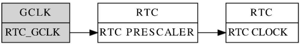
flowchart
graph LR
A["GCLK"] --> B["RTC"]
C["RTC_GCLK"] --> B
B --> D["RTC"]
E["RTC_PRESCALER"] --> D
D --> F["RTC_CLOCK"]
13.5 Extra Information
For extra information see Extra Information for RTC COUNT Driver. This includes:
• Acronyms
- Dependencies
Errata
- Module History
13.6 Examples
For a list of examples related to this driver, see Examples for RTC (COUNT) Driver.
13.7 API Overview
13.7.1 Structure Definitions
13.7.1.1 Struct rtc\_count\_config
Configuration structure for the RTC instance. This structure should be initialized using the rtc_count_get_config_defaults() before any user configurations are set.
Table 13-3. Members
| Type Name Description | ||
| bool clear_on_match If true, clears the counter value on | compare match. Only available whilst running in 32-bit mode. | |
| uint32_t compare_values[] Array of Compare values. Not all | Compare values are available in 32-bit mode. | |
| bool continuously_update Continuously update the counter | value so no synchronization is needed for reading. | |
| enum rtc_count_mode mode Select the operation mode of the | RTC. | |
| enum rtc_count_prescaler prescaler Input clock prescaler for the RTC | module. | |
13.7.1.2 Struct rtc\_count\_events
Event flags for the rtc_count_enable_events() and rtc_count_disable_events().
Table 13-4. Members
| Type Name Description | ||
| bool generate_event_on_compare[] Generate an output event on a | compare channel match against the RTC count. | |
| bool generate_event_on_overflow Generate an output event on each | overflow of the RTC count. | |
| bool generate_event_on_periodic[] Generate an output event | periodically at a binary division of the RTC counter frequency (see Periodic Events). | |
13.7.2 Function Definitions
13.7.2.1 Configuration and initialization
Function rtc\_count\_is\_syncing()
Determines if the hardware module(s) are currently synchronizing to the bus.
bool rtc_count_is_syncing(
struct rtc_module *const module)
Checks to see if the underlying hardware peripheral module(s) are currently synchronizing across multiple clock domains to the hardware bus. This function can be used to delay further operations on a module until such time that it is ready, to prevent blocking delays for synchronization in the user application.
Table 13-5. Parameters
| Data direction | Parameter name | Description |
| [in] | module | RTC hardware module |
Returns
Synchronization status of the underlying hardware module(s).
Table 13-6. Return Values
| Return value Description | |
| true if the module has completed synchronization | |
| false if the module synchronization is ongoing |
Function rtc\_count\_get\_config\_defaults()
Gets the RTC default configurations.
void rtc_count_get_config_defaults(
struct rtc_count_config *const config)
Initializes the configuration structure to default values. This function should be called at the start of any RTC initialization.
The default configuration is as follows:
• Input clock divided by a factor of 1024.
- RTC in 32 bit mode.
• Clear on compare match off.
• Continuously sync count register off.
- No event source on.
• All compare values equal 0.
Table 13-7. Parameters
| Data direction Parameter name Description | |
| [out] config Configuration structure to be | initialized to default values. |
Function rtc\_count\_reset()
Resets the RTC module. Resets the RTC to hardware defaults.
void rtc_count_reset(
struct rtc_module *const module)
Table 13-8. Parameters
| Data direction Parameter name Description | |
| [in, out] module Pointer to the software instance | struct |
Function rtc\_count\_enable()
Enables the RTC module.
void rtc_count_enable(
struct rtc_module *const module)
Enables the RTC module once it has been configured, ready for use. Most module configuration parameters cannot be altered while the module is enabled.
Table 13-9. Parameters
| Data direction Parameter name Description | |
| [in, out] module RTC hardware module |
Function rtc\_count\_disable()
Disables the RTC module.
void rtc_count_disable(
struct rtc_module *const module)
Disables the RTC module.
Table 13-10. Parameters
| Data direction Parameter name Description | |
| [in, out] module RTC hardware module |
Function rtc\_count\_init()
Initializes the RTC module with given configurations.
enum status_code rtc_count_init(
struct rtc_module *const module,
Rtc *const hw,
const struct rtc_count_config *const config)
Initializes the module, setting up all given configurations to provide the desired functionality of the RTC.
Table 13-11. Parameters
| Data direction Parameter name Description | |
| [out] module Pointer to the software instance | struct |
| [in] hw Pointer to hardware instance | |
| [in] config Pointer to the configuration | structure. |
Returns
Status of the initialization procedure.
Table 13-12. Return Values
| Return value Description | |
| STATUS_OK If the initialization was run stressfully. |
Return value Description
STATUS_ERR_INVALID_ARG If invalid argument(s) were given.
Function rtc\_count\_frequency\_correction()
Calibrate for too-slow or too-fast oscillator.
enum status_code rtc_count_frequency_correction(
struct rtc_module *const module,
const int8_t value)
When used, the RTC will compensate for an inaccurate oscillator. The RTC module will add or subtract cycles from the RTC prescaler to adjust the frequency in approximately 1 PPM steps. The provided correction value should be between 0 and 127, allowing for a maximum 127 PPM correction.
If no correction is needed, set value to zero.
Note
Can only be used when the RTC is operated in 1Hz.
Table 13-13. Parameters
| Data direction Parameter name Description | |
| [in, out] module Pointer to the software instance | struct |
| [in] value Ranging from -127 to 127 used for | the correction. |
Returns
Status of the calibration procedure.
Table 13-14. Return Values
| Return value Description | |
| STATUS_OK If calibration was executed correctly. | |
| STATUS_ERR_INVALID_ARG If invalid argument(s) were provided. | |
13.7.2.2 Count and compare value management
Function rtc\_count\_set\_count()
Set the current count value to desired value.
enum status_code rtc_count_set_count(
struct rtc_module *const module,
const uint32_t count_value)
Sets the value of the counter to the specified value.
Table 13-15. Parameters
| Data direction Parameter name Description | |
| [in, out] module Pointer to the software instance | struct |
Data direction Parameter name Description
| [in] count_value The value to be set in count | register. |
Returns
Status of setting the register.
Table 13-16. Return Values
| Return value Description | |
| STATUS_OK If everything was executed correctly. | |
| STATUS_ERR_INVALID_ARG If invalid argument(s) were provided. | |
Function rtc\_count\_get\_count()
Get the current count value.
uint32_t rtc_count_get_count(
struct rtc_module *const module)
Table 13-17. Parameters
| Data direction Parameter name Description | |
| [in, out] module Pointer to the software instance | struct |
Returns the current count value.
Returns
The current counter value as a 32 bit unsigned integer.
Function rtc\_count\_set\_compare()
Set the compare value for the specified compare.
enum status_code rtc_count_set_compare(
struct rtc_module *const module,
const uint32_t comp_value,
const enum rtc_count_compare comp_index)
Sets the value specified by the implementer to the requested compare.
Note
Compare 4 and 5 are only available in 16 bit mode.
Table 13-18. Parameters
| Data direction Parameter name Description | |
| [in, out] module Pointer to the software instance | struct |
| [in] comp_value The value to be written to the | compare. |
Data direction Parameter name Description
[in] comp_index Index of the compare to set.
Returns
Status indicating if compare was successfully set.
Table 13-19. Return Values
| Return value Description | |
| STATUS_OK If compare was successfully set. | |
| STATUS_ERR_INVALID_ARG If invalid argument(s) were provided. | |
| STATUS_ERR_BAD_FORMAT If the module was not initialized in a mode. | |
Function rtc\_count\_get\_compare()
Get the current compare value of specified compare.
enum status_code rtc_count_get_compare(
struct rtc_module *const module,
uint32_t *const comp_value,
const enum rtc_count_compare comp_index)
Retrieves the current value of the specified compare.
Note
Compare 4 and 5 are only available in 16 bit mode.
Table 13-20. Parameters
| Data direction Parameter name Description | |
| [in, out] module Pointer to the software instance | struct |
| [out] comp_value Pointer to 32 bit integer that will be | populated with the current compare value. |
| [in] comp_index Index of compare to check. |
Returns
Status of the reading procedure.
Table 13-21. Return Values
| Return value Description | |
| STATUS_OK If the value was read correctly. | |
| STATUS_ERR_INVALID_ARG If invalid argument(s) were provided. | |
| STATUS_ERR_BAD_FORMAT If the module was not initialized in a mode. | |
Function rtc\_count\_set\_period()
Set the given value to the period.
enum status_code rtc_count_set_period(
struct rtc_module *const module,
uint16_t period_value)
Sets the given value to the period.
Note
Only available in 16 bit mode.
Table 13-22. Parameters
| Data direction Parameter name Description | |
| [in, out] module Pointer to the software instance | struct |
| [in] period_value The value to set to the period. |
Returns
Status of setting the period value.
Table 13-23. Return Values
| Return value Description | |
| STATUS_OK If the period was set correctly. | |
| STATUS_ERR_UNSUPPORTED_DEV If module is not operated in 16 bit mode. | |
Function rtc\_count\_get\_period()
Retrieves the value of period.
enum status_code rtc_count_get_period(
struct rtc_module *const module,
uint16_t *const period_value)
Retrieves the value of the period for the 16 bit mode counter.
Note
Only available in 16 bit mode.
Table 13-24. Parameters
| Data direction Parameter name Description | |
| [in, out] module Pointer to the software instance | struct |
| [out] period_value Pointer to value for return | argument. |
Returns
Status of getting the period value.
Table 13-25. Return Values
| Return value Description | |
| STATUS_OK If the period value was read correctly. |
Return value Description
STATUS_ERR_UNSUPPORTED_DEV If incorrect mode was set.
13.7.2.3 Status management
Function rtc\_count\_is\_overflow()
Check if an RTC overflow has occurred.
bool rtc_count_is_overflow(
struct rtc_module *const module)
Checks the overflow flag in the RTC. The flag is set when there is an overflow in the clock.
Table 13-26. Parameters
| Data direction Parameter name Description | |
| [in, out] module RTC hardware module |
Returns
Overflow state of the RTC module.
Table 13-27. Return Values
| Return value Description | |
| true If the RTC count value has overflowed | |
| false If the RTC count value has not overflowed |
Function rtc\_count\_clear\_overflow()
Clears the RTC overflow flag.
void rtc_count_clear_overflow(
struct rtc_module *const module)
Clears the RTC module counter overflow flag, so that new overflow conditions can be detected.
Table 13-28. Parameters
| Data direction Parameter name Description | |
| [in, out] module RTC hardware module |
Function rtc\_count\_is\_compare\_match()
Check if RTC compare match has occurred.
bool rtc_count_is_compare_match(
struct rtc_module *const module,
const enum rtc_count_compare comp_index)
Checks the compare flag to see if a match has occurred. The compare flag is set when there is a compare match between counter and the compare.
Note
Compare 4 and 5 are only available in 16 bit mode.
Table 13-29. Parameters
| Data direction Parameter name Description | |
| [in, out] module Pointer to the software instance | struct |
| [in] comp_index Index of compare to check current | flag. |
Function rtc\_count\_clear\_compare\_match()
Clears RTC compare match flag.
enum status_code rtc_count_clear_compare_match(
struct rtc_module *const module,
const enum rtc_count_compare_comp_index)
Clears the compare flag. The compare flag is set when there is a compare match between the counter and the compare.
Note
Compare 4 and 5 are only available in 16 bit mode.
Table 13-30. Parameters
| Data direction Parameter name Description | |
| [in, out] module Pointer to the software instance | struct |
| [in] comp_index Index of compare to check current | flag. |
Returns
Status indicating if flag was successfully cleared.
Table 13-31. Return Values
| Return value Description | |
| STATUS_OK If flag was successfully cleared. | |
| STATUS_ERR_INVALID_ARG If invalid argument(s) were provided. | |
| STATUS_ERR_BAD_FORMAT If the module was not initialized in a mode. | |
13.7.2.4 Event management
Function rtc_count_enable_events()
Enables a RTC event output.
void rtc_count_enable_events(
struct rtc_module *const module,
struct rtc_count_events *const events)
Enables one or more output events from the RTC module. See rtc_count_events for a list of events this module supports.
Note
Events cannot be altered while the module is enabled.
Table 13-32. Parameters
| Data direction Parameter name Description | |
| [in, out] module RTC hardware module | |
| [in] events Struct containing flags of events to | enable |
Function rtc\_count\_disable\_events()
Disables a RTC event output.
void rtc_count_disable_events(
struct rtc_module *const module,
struct rtc_count_events *const events)
Disabled one or more output events from the RTC module. See rtc_count_events for a list of events this module supports.
Note
Events cannot be altered while the module is enabled.
Table 13-33. Parameters
| Data direction Parameter name Description | |
| [in, out] module RTC hardware module | |
| [in] events Struct containing flags of events to | disable |
13.7.2.5 Callbacks
Function rtc\_count\_register\_callback()
Registers callback for the specified callback type.
enum status_code rtc_count_register_callback(
struct rtc_module *const module,
rtc_count_callback_t callback,
enum rtc_count_callback callback_type)
Associates the given callback function with the specified callback type. To enable the callback, the rtc_count_enable_callback function must be used.
Table 13-34. Parameters
| Data direction Parameter name Description | |
| [in, out] module Pointer to the software instance | struct |
| [in] callback Pointer to the function desired for | the specified callback |
| [in] callback_type Callback type to register |
Returns
Status of registering callback
Table 13-35. Return Values
| Return value Description | |
| STATUS_OK Registering was done successfully | |
| STATUS_ERR_INVALID_ARG If trying to register a callback not available | |
Function rtc\_count\_unregister\_callback()
Unregisters callback for the specified callback type.
enum status_code rtc_count_unregister_callback(
struct rtc_module *const module,
enum rtc_count_callback callback_type)
When called, the currently registered callback for the given callback type will be removed.
Table 13-36. Parameters
| Data direction Parameter name Description | |
| [in, out] module Pointer to the software instance | struct |
| [in] callback_type Specifies the callback type to | unregister |
Returns
Status of unregistering callback
Table 13-37. Return Values
| Return value Description | |
| STATUS_OK Unregistering was done successfully | |
| STATUS_ERR_INVALID_ARG If trying to unregister a callback not available | |
Function rtc\_count\_enable\_callback()
Enables callback.
void rtc_count_enable_callback(
struct rtc_module *const module,
enum rtc_count_callback callback_type)
Enables the callback specified by the callback_type.
Table 13-38. Parameters
| Data direction Parameter name Description | |
| [in, out] module Pointer to the software instance | struct |
| [in] callback_type Callback type to enable |
Function rtc\_count\_disable\_callback()
Disables callback.
void rtc_count_disable_callback(
struct rtc_module *const module,
enum rtc_count_callback callback_type)
Disables the callback specified by the callback_type.
Table 13-39. Parameters
| Data direction Parameter name Description | |
| [in, out] module Pointer to the software instance | struct |
| [in] callback_type Callback type to disable |
13.7.3 Enumeration Definitions
13.7.3.1 Enum rtc\_count\_callback
The available callback types for the RTC count module.
Table 13-40. Members
| Enum value Description | |
| RTC_COUNT_CALLBACK_COMPARE_0 | Callback for compare channel 0 |
| RTC_COUNT_CALLBACK_COMPARE_1 | Callback for compare channel 1 |
| RTC_COUNT_CALLBACK_COMPARE_2 | Callback for compare channel 2 |
| RTC_COUNT_CALLBACK_COMPARE_3 | Callback for compare channel 3 |
| RTC_COUNT_CALLBACK_COMPARE_4 | Callback for compare channel 4 |
| RTC_COUNT_CALLBACK_COMPARE_5 | Callback for compare channel 5 |
| RTC_COUNT_CALLBACK_OVERFLOW | Callback for overflow |
13.7.3.2 Enum rtc\_count\_compare
Note
Not all compare channels are available in all devices and modes.
Table 13-41. Members
| Enum value Description | |
| RTC_COUNT_COMPARE_0 Compare channel 0. | |
| RTC_COUNT_COMPARE_1 Compare channel 1. | |
| RTC_COUNT_COMPARE_2 Compare channel 2. | |
| RTC_COUNT_COMPARE_3 Compare channel 3. | |
| RTC_COUNT_COMPARE_4 Compare channel 4. | |
| RTC_COUNT_COMPARE_5 Compare channel 5. |
13.7.3.3 Enum rtc\_count\_mode
RTC Count operating modes, to select the counting width and associated module operation.
Table 13-42. Members
| Enum value Description | |
| RTC_COUNT_MODE_16BIT RTC Count module operates in 16-bit mode. | |
| RTC_COUNT_MODE_32BIT RTC Count module operates in 32-bit mode. | |
13.7.3.4 Enum rtc\_count\_prescaler
The available input clock prescaler values for the RTC count module.
Table 13-43. Members
| Enum value Description | |
| RTC_COUNT_PRESCALER_DIV_1 RTC input clock frequency is prescaled by a factor of 1. | |
| RTC_COUNT_PRESCALER_DIV_2 RTC input clock frequency is prescaled by a factor of 2. | |
| RTC_COUNT_PRESCALER_DIV_4 RTC input clock frequency is prescaled by a factor of 4. | |
| RTC_COUNT_PRESCALER_DIV_8 RTC input clock frequency is prescaled by a factor of 8. | |
| RTC_COUNT_PRESCALER_DIV_16 RTC input clock frequency is prescaled by a factor of 16. | |
| RTC_COUNT_PRESCALER_DIV_32 RTC input clock frequency is prescaled by a factor of 32. | |
| RTC_COUNT_PRESCALER_DIV_64 RTC input clock frequency is prescaled by a factor of 64. | |
| RTC_COUNT_PRESCALER_DIV_128 RTC input clock frequency is prescaled by a factor of 128. | |
| RTC_COUNT_PRESCALER_DIV_256 RTC input clock frequency is prescaled by a factor of 256. | |
| RTC_COUNT_PRESCALER_DIV_512 RTC input clock frequency is prescaled by a factor of 512. | |
Enum value Description
RTC_COUNT_PRESCALER_DIV_1024 RTC input clock frequency is prescaled by a factor of 1024.
13.8 Extra Information for RTC COUNT Driver
13.8.1 Acronyms
Below is a table listing the acronyms used in this module, along with their intended meanings.
| Acronym Description | |
| RTC Real Time Counter | |
| PPM Part Per Million | |
| RC Resistor/Capacitor |
13.8.2 Dependencies
This driver has the following dependencies:
None
13.8.3 Errata
There are no errata related to this driver.
13.8.4 Module History
An overview of the module history is presented in the table below, with details on the enhancements and fixes made to the module since its first release. The current version of this corresponds to the newest version in the table.
| Changelog |
| Added support for SAMD21 and added driver instance parameter to all API function calls, except get_config_defaults. |
| Updated initialization function to also enable the digital interface clock to the module if it is disabled. |
| Initial Release |
13.9 Examples for RTC (COUNT) Driver
This is a list of the available Quick Start guides (QSGs) and example applications for SAM D20/D21 RTC Count Driver (RTC COUNT). QSGs are simple examples with step-by-step instructions to configure and use this driver in a selection of use cases. Note that QSGs can be compiled as a standalone application or be added to the user application.
- Quick Start Guide for RTC (COUNT) - Basic
- Quick Start Guide for RTC (COUNT) - Callback
13.9.1 Quick Start Guide for RTC (COUNT) - Basic
In this use case, the RTC is set up in count mode. The example configures the RTC in 16 bit mode, with continuous updates to the COUNT register, together with a set compare register value. Every 1000ms a LED on the board is toggled.
13.9.1.1 Prerequisites
The Generic Clock Generator for the RTC should be configured and enabled; if you are using the System Clock driver, this may be done via conf_clocks.h.
Clocks and Oscillators
The conf_clock.h file needs to be changed with the following values to configure the clocks and oscillators for the module.
The following oscillator settings are needed:
/* SYSTEM_CLOCK_SOURCE_OSC32K configuration - Internal 32KHz oscillator */
<h1 id="define-conf_clock_osc32k_enable-true-3">define CONF_CLOCK_OSC32K_ENABLE true</h1>
<h1 id="define-conf_clock_osc32k_startup_time-system_osc32k_startup_130-3">define CONF_CLOCK_OSC32K_STARTUP_TIME SYSTEM_OSC32K_STARTUP_130</h1>
<h1 id="define-conf_clock_osc32k_enable_1khz_output-true-3">define CONF_CLOCK_OSC32K_ENABLE_1KHZ_OUTPUT true</h1>
<h1 id="define-conf_clock_osc32k_enable_32khz_output-true-3">define CONF_CLOCK_OSC32K_ENABLE_32KHZ_OUTPUT true</h1>
<h1 id="define-conf_clock_osc32k_on_demand-true-3">define CONF_CLOCK_OSC32K_ON_DEMAND true</h1>
<h1 id="define-conf_clock_osc32k_run_in_standby-false-3">define CONF_CLOCK_OSC32K_RUN_IN_STANDBY false</h1>
The following generic clock settings are needed:
/* Configure GCLK generator 2 (RTC) */
<h1 id="define-conf_clock_gclk_2_enable-true-3">define CONF_CLOCK_GCLK_2_ENABLE true</h1>
<h1 id="define-conf_clock_gclk_2_run_in_standby-false-3">define CONF_CLOCK_GCLK_2_RUN_IN_STANDBY false</h1>
<h1 id="define-conf_clock_gclk_2_clock_source-system_clock_source_osc32k-3">define CONF_CLOCK_GCLK_2_CLOCK_SOURCE SYSTEM_CLOCK_SOURCE_OSC32K</h1>
<h1 id="define-conf_clock_gclk_2_prescaler-32-3">define CONF_CLOCK_GCLK_2_PRESCALER 32</h1>
<h1 id="define-conf_clock_gclk_2_output_enable-false-3">define CONF_CLOCK_GCLK_2_OUTPUT_ENABLE false</h1>
13.9.1.2 Setup
Initialization Code
Create a rtc_module struct and add to the main application source file, outside of any functions:
struct rtc_module rtc_instance;
Copy-paste the following setup code to your applications main():
void configure_rtc_count(void)
{
struct rtc_count_config config_rtc_count;
rtc_count_get_config_defaults(&config_rtc_count);
config_rtc_count.prescaler = RTC_COUNT_PRESCALER_DIV_1;
config_rtc_count.mode = RTC_COUNT_MODE_16BIT;
config_rtc_count.continuously_update = true;
config_rtc_count.compare_values[0] = 1000;
rtc_count_init(&rtc_instance, RTC, &config_rtc_count);
rtc_count_enable(&rtc_instance);
}
Add to Main
Add the following to your main().
configure_rtc_count();
Workflow
- Create a RTC configuration structure to hold the desired RTC driver settings.
struct rtc_count_config config_rtc_count;
- Fill the configuration structure with the default driver configuration.
rtc_count_get_config_defaults(&config_rtc_count);
Note
This should always be performed before using the configuration struct to ensure that all values are initialized to known default settings.
- Alter the RTC driver configuration to run in 16-bit counting mode, with continuous counter register updates.
config_rtc_count.prescaler = RTC_COUNT_PRESCALER_DIV_1;
config_rtc_count.mode = RTC_COUNT_MODE_16BIT;
config_rtc_count.continuously_update = true;
config_rtc_count.compare_values[0] = 1000;
- Initialize the RTC module.
rtc_count_init(&rtc_instance, RTC, &config_rtc_count);
- Enable the RTC module, so that it may begin counting.
rtc_count_enable(&rtc_instance);
13.9.1.3 Implementation
Code used to implement the initialized module.
Code
Add after initialization in main().
rtc_count_set_period(&rtc_instance, 2000);
while (true) {
if (rtc_count_is_compare_match(&rtc_instance, RTC_COUNT_COMPARE_0)) {
/* Do something on RTC count match here */
port_pin_toggle_output_level(LED_0_PIN);
}
}
Workflow
- Set RTC period to 2000ms (2 seconds) so that it will overflow and reset back to zero every two seconds.
rtc_count_set_period(&rtc_instance, 2000);
- Enter an infinite loop to poll the RTC driver to check when a comparison match occurs.
while (true) {
- Check if the RTC driver has found a match on compare channel 0 against the current RTC count value.
if (rtc_count_is_compare_match(&rtc_instance, RTC_COUNT_COMPARE_0)) {
- Once a compare match occurs, perform the desired user action.
/* Do something on RTC count match here */
port_pin_toggle_output_level(LED_0_PIN);
- Clear the compare match, so that future matches may occur.
rtc_count_clear_compare_match(&rtc_instance, RTC_COUNT_COMPARE_0);
13.9.2 Quick Start Guide for RTC (COUNT) - Callback
In this use case, the RTC is set up in count mode. The quick start configures the RTC in 16 bit mode and to continuously update COUNT register. The rest of the configuration is according to the default. A callback is implemented for when the RTC overflows.
13.9.2.1 Prerequisites
The Generic Clock Generator for the RTC should be configured and enabled; if you are using the System Clock driver, this may be done via conf_clocks.h.
Clocks and Oscillators
The conf_clock.h file needs to be changed with the following values to configure the clocks and oscillators for the module.
The following oscillator settings are needed:
/* SYSTEM_CLOCK_SOURCE_OSC32K configuration - Internal 32KHz oscillator */
<h1 id="define-conf_clock_osc32k_enable-true-4">define CONF_CLOCK_OSC32K_ENABLE true</h1>
<h1 id="define-conf_clock_osc32k_startup_time-system_osc32k_startup_130-4">define CONF_CLOCK_OSC32K_STARTUP_TIME SYSTEM_OSC32K_STARTUP_130</h1>
<h1 id="define-conf_clock_osc32k_enable_1khz_output-true-4">define CONF_CLOCK_OSC32K_ENABLE_1KHZ_OUTPUT true</h1>
<h1 id="define-conf_clock_osc32k_enable_32khz_output-true-4">define CONF_CLOCK_OSC32K_ENABLE_32KHZ_OUTPUT true</h1>
<h1 id="define-conf_clock_osc32k_on_demand-true-4">define CONF_CLOCK_OSC32K_ON_DEMAND true</h1>
<h1 id="define-conf_clock_osc32k_run_in_standby-false-4">define CONF_CLOCK_OSC32K_RUN_IN_STANDBY false</h1>
The following generic clock settings are needed:
/* Configure GCLK generator 2 (RTC) */
<h1 id="define-conf_clock_gclk_2_enable-true-4">define CONF_CLOCK_GCLK_2_ENABLE true</h1>
<h1 id="define-conf_clock_gclk_2_run_in_standby-false-4">define CONF_CLOCK_GCLK_2_RUN_IN_STANDBY false</h1>
<h1 id="define-conf_clock_gclk_2_clock_source-system_clock_source_osc32k-4">define CONF_CLOCK_GCLK_2_CLOCK_SOURCE SYSTEM_CLOCK_SOURCE_OSC32K</h1>
<h1 id="define-conf_clock_gclk_2_prescaler-32-4">define CONF_CLOCK_GCLK_2_PRESCALER 32</h1>
<h1 id="define-conf_clock_gclk_2_output_enable-false-4">define CONF_CLOCK_GCLK_2_OUTPUT_ENABLE false</h1>
13.9.2.2 Setup
Code
Create a rtc_module struct and add to the main application source file, outside of any functions:
struct rtc_module rtc_instance;
The following must be added to the user application:
Function for setting up the module:
void configure_rtc_count(void)
{
struct rtc_count_config config_rtc_count;
rtc_count_get_config_defaults(&config_rtc_count);
config_rtc_count.prescaler = RTC_COUNT_PRESCALER_DIV_1;
config_rtc_count.mode = RTC_COUNT_MODE_16BIT;
config_rtc_count.continuously_update = true;
rtc_count_init(&rtc_instance, RTC, &config_rtc_count);
rtc_count_enable(&rtc_instance);
}
Callback function:
void rtc_overflow_callback(void)
{
/* Do something on RTC overflow here */
port_pin_toggle_output_level(LED_0_PIN);
}
Function for setting up the callback functionality of the driver:
void configure_rtc_callbacks(void)
{
rtc_count_register_callback(&rtc_instance, rtc_overflow_callback, RTC_COUNT_CALLBACK_OVERFLOW);
rtc_count_enable_callback(&rtc_instance, RTC_COUNT_CALLBACK_OVERFLOW);
}
Add to user application main():
/* Initialize system. Must configure conf_clocks.h first. */
system_init();
/* Configure and enable RTC */
configure_rtc_count();
/* Configure and enable callback */
configure_rtc_callbacks();
/* Set period */
rtc_count_set_period(&rtc_instance, 2000);
Workflow
- Initialize system.
system_init();
- Configure and enable module.
configure_rtc_count();
- Create a RTC configuration structure to hold the desired RTC driver settings and fill it with the default driver configuration values.
struct rtc_count_config config_rtc_count;
rtc_count_get_config_defaults(&config_rtc_count);
Note
This should always be performed before using the configuration struct to ensure that all values are initialized to known default settings.
- Alter the RTC driver configuration to run in 16-bit counting mode, with continuous counter register updates and a compare value of 1000ms.
config_rtc_count.prescaler = RTC_COUNT_PRESCALER_DIV_1;
config_rtc_count.mode = RTC_COUNT_MODE_16BIT;
config_rtc_count.continuously_update = true;
- Initialize the RTC module.
rtc_count_init(&rtc_instance, RTC, &config_rtc_count);
- Enable the RTC module, so that it may begin counting.
rtc_count_enable(&rtc_instance);
- Configure callback functionality.
configure_rtc_callbacks();
a. Register overflow callback.
rtc_count_register_callback(
&rtc_instance, rtc_overflow_callback, RTC_COUNT_CALLBACK_OVERFLOW);
b. Enable overflow callback.
rtc_count_enable_callback(&rtc_instance, RTC_COUNT_CALLBACK_OVERFLOW);
- Set period.
rtc_count_set_period(&rtc_instance, 2000);
13.9.2.3 Implementation
Code
Add to user application main:
while (true) {
/* Infinite while loop */
}
Workflow
- Infinite while loop while waiting for callbacks.
while (true) {
/* Infinite while loop */
}
13.9.2.4 Callback
Each time the RTC counter overflows, the callback function will be called.
Workflow
- Perform the desired user action for each RTC overflow:
/* Do something on RTC overflow here */
port_pin_toggle_output_level(LED_0_PIN);
14. SAM D20/D21 Serial Peripheral Interface Driver (SERCOM SPI)
This driver for SAM D20/D21 devices provides an interface for the configuration and management of the SERCOM module in its SPI mode to transfer SPI data frames. The following driver API modes are covered by this manual:
- Polled APIs
- Callback APIs
The following peripherals are used by this module:
• SERCOM (Serial Communication Interface)
The outline of this documentation is as follows:
- Prerequisites
- Module Overview
• Special Considerations - Extra Information
- Examples
- API Overview
14.1 Prerequisites
There are no prerequisites.
14.2 Module Overview
The Serial Peripheral Interface (SPI) is a high-speed synchronous data transfer interface using three or four pins. It allows fast communication between a master device and one or more peripheral devices.
A device connected to the bus must act as a master or a slave. The master initiates and controls all data transactions. The SPI master initiates a communication cycle by pulling low the Slave Select (SS) pin of the desired slave. The Slave Select pin is active low. Master and slave prepare data to be sent in their respective shift registers, and the master generates the required clock pulses on the SCK line to interchange data. Data is always shifted from master to slave on the Master Out - Slave In (MOSI) line, and from slave to master on the Master In - Slave Out (MISO) line. After each data transfer, the master can synchronize to the slave by pulling the SS line high.
14.2.1 Driver Feature Macro Definition
| Driver Feature Macro Supported devices | |
| FEATURE_SPI_SLAVE_SELECT_LOW_DETECT SAMD21 | |
| FEATURE_SPI_HARDWARE_SLAVE_SELECT SAMD21 | |
| FEATURE_SPI_ERROR_INTERRUPT SAMD21 | |
Note
The specific features are only available in the driver when the selected device supports those features.
14.2.2 SPI Bus Connection
In Figure 14-1: SPI Bus Connection on page 317, the connection between one master and one slave is shown.
Figure 14-1. SPI Bus Connection
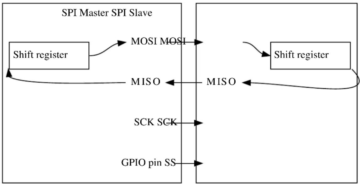
flowchart
graph LR
A["Shift register"] -->|MOSI MOSI| B["MISO"]
B -->|MISO| C["Shift register"]
C -->|MISO| B
D["SCK SCK"] --> B
E["GPIO pin SS"] --> B
F["SPI Master SPI Slave"] --> A
F --> C
The different lines are as follows:
- MOSI Master Input Slave Output. The line where the data is shifted out from the master and in to the slave.
• MISO Master Output Slave Input. The line where the data is shifted out from the slave and in to the master. - SCK Serial Clock. Generated by the master device.
- SS Slave Select. To initiate a transaction, the master must pull this line low.
If the bus consists of several SPI slaves, they can be connected in parallel and the SPI master can use general I/O pins to control separate SS lines to each slave on the bus.
It is also possible to connect all slaves in series. In this configuration, a common SS is provided to N slaves, enabling them simultaneously. The MISO from the N-1 slaves is connected to the MOSI on the next slave. The Nth slave connects its MISO back to the master. For a complete transaction, the master must shift N+1 characters.
14.2.3 SPI Character Size
The SPI character size is configurable to 8 or 9 bits.
14.2.4 Master Mode
When configured as a master, the SS pin will be configured as an output.
14.2.4.1 Data Transfer
Writing a character will start the SPI clock generator, and the character is transferred to the shift register when the shift register is empty. Once this is done, a new character can be written. As each character is shifted out from the master, a character is shifted in from the slave. If the receiver is enabled, the data is moved to the receive buffer at the completion of the frame and can be read.
14.2.5 Slave Mode
When configured as a slave, the SPI interface will remain inactive with MISO tri-stated as long as the SS pin is driven high.
14.2.5.1 Data Transfer
The data register can be updated at any time. As the SPI slave shift register is clocked by SCK, a minimum of three SCK cycles are needed from the time new data is written, until the character is ready to be shifted out. If the shift register has not been loaded with data, the current contents will be transmitted.
If constant transmission of data is needed in SPI slave mode, the system clock should be faster than SCK. If the receiver is enabled, the received character can be read from the. When SS line is driven high, the slave will not receive any additional data.
14.2.5.2 Address Recognition
When the SPI slave is configured with address recognition, the first character in a transaction is checked for an address match. If there is a match, the MISO output is enabled and the transaction is processed. If the address does not match, the complete transaction is ignored.
If the device is asleep, it can be woken up by an address match in order to process the transaction.
Note
In master mode, an address packet is written by the spi_select_slave function if the address_enabled configuration is set in the spi_slave_inst_config struct.
14.2.6 Data Modes
There are four combinations of SCK phase and polarity with respect to serial data. Table 14-1: SPI Data Modes on page 318 shows the clock polarity (CPOL) and clock phase (CPHA) in the different modes. Leading edge is the first clock edge in a clock cycle and trailing edge is the last clock edge in a clock cycle.
Table 14-1. SPI Data Modes
| Mode CPOL CPHA Leading Edge Trailing Edge | ||||
| 0 0 0 Rising, Sample Falling, Setup | ||||
| 1 0 1 Rising, Setup Falling, Sample | ||||
| 2 1 0 Falling, Sample Rising, Setup | ||||
| 3 1 1 Falling, Setup Rising, Sample | ||||
14.2.7 SERCOM Pads
The SERCOM pads are automatically configured as seen in Table 14-2: SERCOM SPI Pad Usages on page 318. If the receiver is disabled, the data input (MISO for master, MOSI for slave) can be used for other purposes.
In master mode, the SS pin(s) must be configured using the spi_slave_inst struct.
Table 14-2. SERCOM SPI Pad Usages
| Pin Master SPI Slave SPI | ||
| MOSI Output | Input | |
| MISO Input | Output | |
| SCK | Output | Input |
| SS | User defined output enable | Input |
14.2.8 Operation in Sleep Modes
The SPI module can operate in all sleep modes by setting the run_in_standby option in the spi_config struct. The operation in slave and master mode is shown in the table below.
| run_in_standby | Slave | Master |
| false | Disabled, all reception is dropped | GCLK disabled when master is idle, wake on transmit complete |
| run_in_standby Slave Master | ||
| true Wake on reception GCLK is enabled while in sleep | modes, wake on all interrupts | |
14.2.9 Clock Generation
In SPI master mode, the clock (SCK) is generated internally using the SERCOM baud rate generator. In SPI slave mode, the clock is provided by an external master on the SCK pin. This clock is used to directly clock the SPI shift register.
14.3 Special Considerations
14.3.1 Pin MUX Settings
The pin MUX settings must be configured properly, as not all settings can be used in different modes of operation.
14.4 Extra Information
For extra information see Extra Information for SERCOM SPI Driver. This includes:
- Acronyms
- Dependencies
• Workarounds Implemented by Driver - Module History
14.5 Examples
For a list of examples related to this driver, see Examples for SERCOM SPI Driver.
14.6 API Overview
14.6.1 Variable and Type Definitions
14.6.1.1 Type spi_callback_t
typedef void(* spi_callback_t )(const struct spi_module *const module)
Type of the callback functions
14.6.2 Structure Definitions
14.6.2.1 Struct spi_config
Configuration structure for an SPI instance. This structure should be initialized by the spi_get_config_defaults function before being modified by the user application.
Table 14-3. Members
| Type Name Description | ||
| enum spi_character_size character_size SPI character size | ||
| enum spi_data_order data_order Data order | ||
| enum gclk_generator | generator_source | GCLK generator to use as clock source. |
| bool | master_slave_select_enable | Enable Master Slave Select |
| enum spi_mode mode SPI mode | ||
| union spi_config.mode_specific mode_specific Union for slave or master specific configuration | ||
| enum spi_signal_mux_setting mux_setting Mux setting | ||
| uint32_t pinmux_pad0 PAD0 pinmux | ||
| uint32_t pinmux_pad1 PAD1 pinmux | ||
| uint32_t pinmux_pad2 PAD2 pinmux | ||
| uint32_t pinmux_pad3 PAD3 pinmux | ||
| bool receiver_enable Enable receiver | ||
| bool run_in_standby Enabled in sleep modes | ||
| bool select_slave_low_detect_enable Enable Slave Select Low Detect | ||
| enum spi_transfer_mode transfer_mode Transfer mode | ||
14.6.2.2 Union spi\_config.mode\_specific
Union for slave or master specific configuration
Table 14-4. Members
| Type Name Description | ||
| struct spi_master_config | master | Master specific configuration |
| struct spi_slave_config | slave | Slave specific configuration |
14.6.2.3 Struct spi\_master\_config
SPI Master configuration structure
Table 14-5. Members
| Type Name Description | ||
| uint32_t baudrate | Baud rate |
14.6.2.4 Struct spi\_module
SERCOM SPI driver software instance structure, used to retain software state information of an associated hardware module instance.
Note
The fields of this structure should not be altered by the user application; they are reserved for module-internal use only.
14.6.2.5 Struct spi\_slave\_config
SPI slave configuration structure
Table 14-6. Members
| Type Name Description | ||
| uint8_t | address Address | |
| uint8_t address_mask Address mask | ||
| enum spi_addr_mode address_mode Address mode | ||
| enum spi_frame_format frame_format Frame format | ||
| bool preload_enable Preload data to the shift register | while SS is high |
14.6.2.6 Struct spi\_slave\_inst
SPI peripheral slave software instance structure, used to configure the correct SPI transfer mode settings for an attached slave. See spi_select_slave.
Table 14-7. Members
| Type Name Description | ||
| uint8_t address Address of slave device | ||
| bool address_enabled Address recognition enabled in | slave device | |
| uint8_t ss_pin Pin to use as Slave Select |
14.6.2.7 Struct spi\_slave\_inst\_config
SPI Peripheral slave configuration structure
Table 14-8. Members
| Type Name Description | ||
| uint8_t address Address of slave | ||
| bool address_enabled Enable address | ||
| uint8_t ss_pin Pin to use as Slave Select |
14.6.3 Macro Definitions
14.6.3.1 Driver feature definition
Define SERCOM SPI features set according to different device family.
Macro FEATURE_SPI_SLAVE_SELECT_LOW_DETECT
#define FEATURE_SPI_SLAVE_SELECT_LOW_DETECT
SPI slave select low detection
Macro FEATURE_SPI_HARDWARE_SLAVE_SELECT
#define FEATURE_SPI_HARDWARE_SLAVE_SELECT
Slave select can be controlled by hardware
Macro FEATURE\_SPI\_ERROR\_INTERRUPT
#define FEATURE_SPI_ERROR_INTERRUPT
SPI with error detect feature
14.6.3.2 Macro PINMUX\_DEFAULT
#define PINMUX_DEFAULT 0
SPI sync scheme version 2 Default pin mux
14.6.3.3 Macro PINMUX\_UNUSED
#define PINMUX_UNUSED 0xFFFFFFFF
Unused PIN mux
14.6.3.4 Macro SPI\_TIMEOUT
#define SPI_TIMEOUT 10000
SPI timeout value
14.6.4 Function Definitions
14.6.4.1 Driver initialization and configuration
Function spi\_get\_config\_defaults()
Initializes an SPI configuration structure to default values.
void spi_get_config_defaults(
struct spi_config *const config)
This function will initialize a given SPI configuration structure to a set of known default values. This function should be called on any new instance of the configuration structures before being modified by the user application.
The default configuration is as follows:
• Master mode enabled
• MSB of the data is transmitted first
- Transfer mode 0
- MUX Setting D
• Character size 8 bit
• Not enabled in sleep mode
- Receiver enabled
- Baudrate 100000
- Default pinmux settings for all pads
• GCLK generator 0
Table 14-9. Parameters
| Data direction Parameter name Description | |
| [out] config Configuration structure to initialize | to default values |
Function spi\_slave\_inst\_get\_config\_defaults()
Initializes an SPI peripheral slave device configuration structure to default values.
void spi_slave_inst_get_config_defaults(
struct spi_slave_inst_config *const config)
This function will initialize a given SPI slave device configuration structure to a set of known default values. This function should be called on any new instance of the configuration structures before being modified by the user application.
The default configuration is as follows:
- Slave Select on GPIO pin 10
- Addressing not enabled
Table 14-10. Parameters
| Data direction Parameter name Description | |
| [out] config Configuration structure to initialize | to default values |
Function spi\_attach\_slave()
Attaches an SPI peripheral slave.
void spi_attach_slave(
struct spi_slave_inst *const slave,
struct spi_slave_inst_config *const config)
This function will initialize the software SPI peripheral slave, based on the values of the config struct. The slave can then be selected and optionally addressed by the spi_select_slave function.
Table 14-11. Parameters
| Data direction Parameter name Description | |
| [out] slave Pointer to the software slave | instance struct |
Data direction Parameter name Description
[in] config Pointer to the config struct
Function spi\_init()
Initializes the SERCOM SPI module.
enum status_code spi_init(
struct spi_module *const module,
Sercom *const hw,
const struct spi_config *const config)
This function will initialize the SERCOM SPI module, based on the values of the config struct.
Table 14-12. Parameters
| Data direction Parameter name Description | |
| [out] module Pointer to the software instance | struct |
| [in] hw Pointer to hardware instance | |
| [in] config Pointer to the config struct |
Returns
Status of the initialization
Table 14-13. Return Values
| Return value Description | |
| STATUS_OK Module initiated correctly. | |
| STATUS_ERR_DENIED If module is enabled. | |
| STATUS_BUSY If module is busy resetting. | |
| STATUS_ERR_INVALID_ARG If invalid argument(s) were provided. | |
14.6.4.2 Enable/Disable
Function spi\_enable()
Enables the SERCOM SPI module.
void spi_enable(
struct spi_module *const module)
This function will enable the SERCOM SPI module.
Table 14-14. Parameters
| Data direction Parameter name Description | |
| [in, out] module Pointer to the software instance | struct |
Function spi\_disable()
Disables the SERCOM SPI module.
void spi_disable(
struct spi_module *const module)
This function will disable the SERCOM SPI module.
Table 14-15. Parameters
| Data direction Parameter name Description | |
| [in, out] module Pointer to the software instance | struct |
Function spi\_reset()
Resets the SPI module.
void spi_reset(
struct spi_module *const module)
This function will reset the SPI module to its power on default values and disable it.
Table 14-16. Parameters
| Data direction Parameter name Description | |
| [in, out] module Pointer to the software instance | struct |
14.6.4.3 Lock/Unlock
Function spi\_lock()
Attempt to get lock on driver instance.
enum status_code spi_lock(
struct spi_module *const module)
This function checks the instance's lock, which indicates whether or not it is currently in use, and sets the lock if it was not already set.
The purpose of this is to enable exclusive access to driver instances, so that, e.g., transactions by different services will not interfere with each other.
Table 14-17. Parameters
| Data direction Parameter name Description | |
| [in, out] module Pointer to the driver instance to | lock. |
Table 14-18. Return Values
| Return value Description | |
| STATUS_OK if the module was locked. |
Return value Description
STATUS_BUSY if the module was already locked.
Function spi\_unlock()
Unlock driver instance.
void spi_unlock(
struct spi_module *const module)
This function clears the instance lock, indicating that it is available for use.
Table 14-19. Parameters
| Data direction Parameter name Description | |
| [in, out] module Pointer to the driver instance to | lock. |
Table 14-20. Return Values
| Return value Description | |
| STATUS_OK if the module was locked. | |
| STATUS_BUSY if the module was already locked. |
14.6.4.4 Ready to write/read
Function spi\_is\_write\_complete()
Checks if the SPI in master mode has shifted out last data, or if the master has ended the transfer in slave mode.
bool spi_is_write_complete(
struct spi_module *const module)
This function will check if the SPI master module has shifted out last data, or if the slave select pin has been drawn high by the master for the SPI slave module.
Table 14-21. Parameters
| Data direction Parameter name Description | |
| [in] module Pointer to the software instance | struct |
Returns
Indication of whether any writes are ongoing
Table 14-22. Return Values
| Return value Description | |
| true If the SPI master module has shifted out data, or slave | select has been drawn high for SPI slave |
Return value Description
false If the SPI master module has not shifted out data
Function spi\_is\_ready\_to\_write()
Checks if the SPI module is ready to write data.
bool spi_is_ready_to_write(
struct spi_module *const module)
This function will check if the SPI module is ready to write data.
Table 14-23. Parameters
| Data direction Parameter name Description | |
| [in] module Pointer to the software instance | struct |
Returns
Indication of whether the module is ready to read data or not
Table 14-24. Return Values
| Return value Description | |
| true If the SPI module is ready to write data | |
| false If the SPI module is not ready to write data |
Function spi\_is\_ready\_to\_read()
Checks if the SPI module is ready to read data.
bool spi_is_ready_to_read(
struct spi_module *const module)
This function will check if the SPI module is ready to read data.
Table 14-25. Parameters
| Data direction Parameter name Description | |
| [in] module Pointer to the software instance | struct |
Returns
Indication of whether the module is ready to read data or not
Table 14-26. Return Values
| Return value Description | |
| true If the SPI module is ready to read data |
Return value Description
false If the SPI module is not ready to read data
14.6.4.5 Read/Write
Function spi\_write()
Transfers a single SPI character.
enum status_code spi_write(
struct spi_module * module,
uint16_t tx_data)
This function will send a single SPI character via SPI and ignore any data shifted in by the connected device.
To both send and receive data, use the spi_transceive_wait function or use the spi_read function after writing a character. The spi_is_ready_to_write function should be called before calling this function.
Note that this function does not handle the SS (Slave Select) pin(s) in master mode; this must be handled from the user application.
Note
In slave mode, the data will not be transferred before a master initiates a transaction.
Table 14-27. Parameters
| Data direction Parameter name Description | |
| [in] module Pointer to the software instance | struct |
| [in] tx_data Data to transmit |
Returns
Status of the procedure
Table 14-28. Return Values
| Return value Description | |
| STATUS_OK If the data was written | |
| STATUS_BUSY If the last write was not completed |
Function spi\_write\_buffer\_wait()
Sends a buffer of length SPI characters.
enum status_code spi_write_buffer_wait(
struct spi_module *const module,
const uint8_t * tx_data,
uint16_t length)
This function will send a buffer of SPI characters via the SPI and discard any data that is received. To both send and receive a buffer of data, use the spi_transceive_buffer_wait function.
Note that this function does not handle the _SS (slave select) pin(s) in master mode; this must be handled by the user application.
Table 14-29. Parameters
| Data direction Parameter name Description | |
| [in] module Pointer to the software instance | struct |
| [in] tx_data Pointer to the buffer to transmit | |
| [in] length Number of SPI characters to | transfer |
Returns
Status of the write operation
Table 14-30. Return Values
| Return value Description | |
| STATUS_OK If the write was completed | |
| STATUS_ABORTED If transaction was ended by master before entire buffer was transferred | |
| STATUS_ERR_INVALID_ARG If invalid argument(s) were provided | |
| STATUS_ERR_TIMEOUT If the operation was not completed within the timeout in slave mode |
Function spi\_read()
Reads last received SPI character.
enum status_code spi_read(
struct spi_module *const module,
uint16_t * rx_data)
This function will return the last SPI character shifted into the receive register by the spi_write function
Note
The spi_is_ready_to_read function should be called before calling this function.
Receiver must be enabled in the configuration
Table 14-31. Parameters
| Data direction Parameter name Description | |
| [in] module Pointer to the software instance | struct |
| [out] rx_data Pointer to store the received data |
Returns
Status of the read operation.
Table 14-32. Return Values
| Return value Description | |
| STATUS_OK If data was read | |
| STATUS_ERR_IO If no data is available | |
| STATUS_ERR_OVERFLOW If the data is overflown |
Function spi\_read\_buffer\_wait()
Reads buffer of length SPI characters.
enum status_code spi_read_buffer_wait(
struct spi_module *const module,
uint8_t * rx_data,
uint16_t length,
uint16_t dummy)
This function will read a buffer of data from an SPI peripheral by sending dummy SPI character if in master mode, or by waiting for data in slave mode.
Note
If address matching is enabled for the slave, the first character received and placed in the buffer will be the address.
Table 14-33. Parameters
| Data direction Parameter name Description | |
| [in] module Pointer to the software instance | struct |
| [out] rx_data Data buffer for received data | |
| [in] length Length of data to receive | |
| [in] dummy 8- or 9-bit dummy byte to shift out | in master mode |
Returns
Status of the read operation
Table 14-34. Return Values
| Return value Description | |
| STATUS_OK If the read was completed | |
| STATUS_ABORTED If transaction was ended by master before entire buffer was transferred | |
| STATUS_ERR_INVALID_ARG If invalid argument(s) were provided. | |
| STATUS_ERR_TIMEOUT If the operation was not completed within the timeout in slave mode. | |
| STATUS_ERR_DENIED | If the receiver is not enabled |
| STATUS_ERR_OVERFLOW If the data is overflown | |
Function spi_transceive_wait()
Sends and reads a single SPI character.
enum status_code spi_transceive_wait(
struct spi_module *const module,
uint16_t tx_data,
uint16_t * rx_data)
This function will transfer a single SPI character via SPI and return the SPI character that is shifted into the shift register.
In master mode the SPI character will be sent immediately and the received SPI character will be read as soon as the shifting of the data is complete.
In slave mode this function will place the data to be sent into the transmit buffer. It will then block until an SPI master has shifted a complete SPI character, and the received data is available.
Note
The data to be sent might not be sent before the next transfer, as loading of the shift register is dependent on SCK.
If address matching is enabled for the slave, the first character received and placed in the buffer will be the address.
Table 14-35. Parameters
| Data direction Parameter name Description | |
| [in] module Pointer to the software instance | struct |
| [in] tx_data SPI character to transmit | |
| [out] rx_data Pointer to store the received SPI | character |
Returns
Status of the operation.
Table 14-36. Return Values
| Return value Description | |
| STATUS_OK If the operation was completed | |
| STATUS_ERR_TIMEOUT If the operation was not completed within the timeout in slave mode | |
| STATUS_ERR_DENIED If the receiver is not enabled | |
| STATUS_ERR_OVERFLOW If the incoming data is overflown |
Function spi\_transceive\_buffer\_wait()
Sends and receives a buffer of length SPI characters.
enum status_code spi_transceive_buffer_wait(
struct spi_module *const module,
uint8_t * tx_data,
uint8_t * rx_data,
uint16_t length)
This function will send and receive a buffer of data via the SPI.
In master mode the SPI characters will be sent immediately and the received SPI character will be read as soon as the shifting of the SPI character is complete.
In slave mode this function will place the data to be sent into the transmit buffer. It will then block until an SPI master has shifted the complete buffer and the received data is available.
Table 14-37. Parameters
| Data direction Parameter name Description | |
| [in] module Pointer to the software instance | struct |
| [in] tx_data Pointer to the buffer to transmit | |
| [out] rx_data Pointer to the buffer where | received data will be stored |
| [in] length Number of SPI characters to | transfer |
Returns
Status of the operation
Table 14-38. Return Values
| Return value Description | |
| STATUS_OK If the operation was completed | |
| STATUS_ERR_INVALID_ARG If invalid argument(s) were provided. | |
| STATUS_ERR_TIMEOUT If the operation was not completed within the timeout in slave mode. | |
| STATUS_ERR_DENIED If the receiver is not enabled | |
| STATUS_ERR_OVERFLOW If the data is overflown | |
Function spi\_select\_slave()
Selects slave device.
enum status_code spi_select_slave(
struct spi_module *const module,
struct spi_slave_inst *const slave,
bool select)
This function will drive the slave select pin of the selected device low or high depending on the select boolean. If slave address recognition is enabled, the address will be sent to the slave when selecting it.
Table 14-39. Parameters
| Data direction Parameter name Description | |
| [in] module Pointer to the software module | struct |
| [in] slave Pointer to the attached slave | |
| [in] select Boolean stating if the slave should | be selected or deselected |
Returns
Status of the operation
Table 14-40. Return Values
| Return value Description | |
| STATUS_OK If the slave device was selected | |
| STATUS_ERR_UNSUPPORTED_DEV If the SPI module is operating in slave mode | |
| STATUS_BUSY If the SPI module is not ready to write the slave address | |
14.6.4.6 Callback Management
Function spi\_register\_callback()
Registers a SPI callback function.
void spi_register_callback(
struct spi_module *const module,
spi_callback_t callback_func,
enum spi_callback callback_type)
Registers a callback function which is implemented by the user.
Note
The callback must be enabled by spi_enable_callback, in order for the interrupt handler to call it when the conditions for the callback type are met.
Table 14-41. Parameters
| Data direction Parameter name Description | |
| [in] module Pointer to USART software | instance struct |
| [in] callback_func Pointer to callback function | |
| [in] callback_type Callback type given by an enum |
Function spi\_unregister\_callback()
Unregisters a SPI callback function.
void spi_unregister_callback(
struct spi_module * module,
enum spi_callback callback_type)
Unregisters a callback function which is implemented by the user.
Table 14-42. Parameters
| Data direction Parameter name Description | |
| [in] module Pointer to SPI software instance | struct |
| [in] callback_type Callback type given by an enum |
Function spi\_enable\_callback()
Enables a SPI callback of a given type.
void spi_enable_callback(
struct spi_module *const module,
enum spi_callback callback_type)
Enables the callback function registered by the spi_register_callback. The callback function will be called from the interrupt handler when the conditions for the callback type are met.
Table 14-43. Parameters
| Data direction Parameter name Description | |
| [in] module Pointer to SPI software instance | struct |
| [in] callback_type Callback type given by an enum |
Function spi\_disable\_callback()
Disables callback.
void spi_disable_callback(
struct spi_module *const module,
enum spi_callback callback_type)
Disables the callback function registered by the spi_register_callback, and the callback will not be called from the interrupt routine.
Table 14-44. Parameters
| Data direction Parameter name Description | |
| [in] module Pointer to SPI software instance | struct |
| [in] callback_type Callback type given by an enum |
14.6.4.7 Writing and Reading
Function spi\_write\_buffer\_job()
Asynchronous buffer write.
enum status_code spi_write_buffer_job(
struct spi_module *const module,
uint8_t * tx_data,
uint16_t length)
Sets up the driver to write to the SPI from a given buffer. If registered and enabled, a callback function will be called when the write is finished.
Table 14-45. Parameters
| Data direction Parameter name Description | |
| [in] module Pointer to USART software | instance struct |
| [out] tx_data Pointer to data buffer to receive | |
| [in] length Data buffer length |
Returns
Status of the write request operation.
Table 14-46. Return Values
| Return value Description | |
| STATUS_OK If the operation completed successfully | |
| STATUS_ERR_BUSY If the SPI was already busy with a write operation | |
| STATUS_ERR_INVALID_ARG If requested write length was zero |
Function spi\_read\_buffer\_job()
Asynchronous buffer read.
enum status_code spi_read_buffer_job(
struct spi_module *const module,
uint8_t * rx_data,
uint16_t length,
uint16_t dummy)
Sets up the driver to read from the SPI to a given buffer. If registered and enabled, a callback function will be called when the read is finished.
Note
If address matching is enabled for the slave, the first character received and placed in the RX buffer will be the address.
Table 14-47. Parameters
| Data direction Parameter name Description | |
| [in] module Pointer to SPI software instance | struct |
| [out] rx_data Pointer to data buffer to receive | |
| [in] length Data buffer length |
| Data direction Parameter name Description | |
| [in] dummy Dummy character to send when | reading in master mode. |
Returns
Status of the operation
Table 14-48. Return Values
| Return value Description | |
| STATUS_OK If the operation completed successfully | |
| STATUS_ERR_BUSY If the SPI was already busy with a read operation | |
| STATUS_ERR_DENIED If the receiver is not enabled | |
| STATUS_ERR_INVALID_ARG If requested read length was zero | |
Function spi\_transceive\_buffer\_job()
Asynchronous buffer write and read.
enum status_code spi_transceive_buffer_job(
struct spi_module *const module,
uint8_t * tx_data,
uint8_t * rx_data,
uint16_t length)
Sets up the driver to write and read to and from given buffers. If registered and enabled, a callback function will be called when the transfer is finished.
Note
If address matching is enabled for the slave, the first character received and placed in the RX buffer will be the address.
Table 14-49. Parameters
| Data direction Parameter name Description | |
| [in] module Pointer to SPI software instance | struct |
| [in] tx_data Pointer to data buffer to send | |
| [out] rx_data Pointer to data buffer to receive | |
| [in] length Data buffer length |
Returns
Status of the operation
Table 14-50. Return Values
| Return value Description | |
| STATUS_OK If the operation completed successfully | |
| STATUS_ERR_BUSY If the SPI was already busy with a read operation | |
| STATUS_ERR_DENIED If the receiver is not enabled |
Return value Description
STATUS_ERR_INVALID_ARG If requested read length was zero
Function spi\_abort\_job()
Aborts an ongoing job.
void spi_abort_job(
struct spi_module *const module)
This function will abort the specified job type.
Table 14-51. Parameters
| Data direction Parameter name Description | |
| [in] module Pointer to SPI software instance | struct |
Function spi\_get\_job\_status()
Retrieves the current status of a job.
enum status_code spi_get_job_status( const struct spi_module *const module)
Retrieves the current statue of a job that was previously issued.
Table 14-52. Parameters
| Data direction Parameter name Description | |
| [in] module Pointer to SPI software instance | struct |
Returns
Current job status.
Function spi\_get\_job\_status\_wait()
Retrieves the status of job once it ends.
enum status_code spi_get_job_status_wait(const struct spi_module *const module)
Waits for current job status to become non-busy, then returns its value.
Table 14-53. Parameters
| Data direction Parameter name Description | |
| [in] module Pointer to SPI software instance | struct |
Returns
Current non-busy job status.
14.6.4.8 Function spi\_is\_syncing()
Determines if the SPI module is currently synchronizing to the bus.
bool spi_is_syncing(
struct spi_module *const module)
This function will check if the underlying hardware peripheral module is currently synchronizing across multiple clock domains to the hardware bus. This function can be used to delay further operations on the module until it is ready.
Table 14-54. Parameters
| Data direction Parameter name Description | |
| [in] module SPI hardware module |
Returns
Synchronization status of the underlying hardware module
Table 14-55. Return Values
| Return value Description | |
| true Module synchronization is ongoing | |
| false Module synchronization is not ongoing |
14.6.4.9 Function spi\_set\_baudrate()
Set the baudrate of the SPI module.
enum status_code spi_set_baudrate(
struct spi_module *const module,
uint32_t baudrate)
This function will set the baudrate of the SPI module.
Table 14-56. Parameters
| Data direction Parameter name Description | |
| [in] module Pointer to the software instance | struct |
| [in] baudrate The baudrate wanted |
Returns
The status of the configuration
Table 14-57. Return Values
| Return value Description | |
| STATUS_ERR_INVALID_ARG If invalid argument(s) were provided. | |
Return value Description
STATUS_OK If the configuration was written
14.6.5 Enumeration Definitions
14.6.5.1 Enum spi\_addr\_mode
For slave mode when using the SPI frame with address format.
Table 14-58. Members
| Enum value Description | |
| SPI_ADDR_MODE_MASK | address_mask in the spi_config struct is used as a mask to the register. |
| SPI_ADDR_MODE_UNIQUE The slave responds to the two unique addresses in address and address_mask in the spi_config struct. | |
| SPI_ADDR_MODE_RANGE The slave responds to the range of addresses between and including address and address_mask in in the spi_config struct. | |
14.6.5.2 Enum spi\_callback
Callbacks for SPI callback driver.
Note
For slave mode, these callbacks will be called when a transaction is ended by the master pulling Slave Select high.
Table 14-59. Members
| Enum value Description | |
| SPI_CALLBACK_BUFFER_TRANSMITTED Callback for buffer transmitted | |
| SPI_CALLBACK_BUFFER_RECEIVED Callback for buffer received | |
| SPI_CALLBACK_BUFFER_TRANSCEIVED Callback for buffers transceived | |
| SPI_CALLBACK_ERROR Callback for error | |
| SPI_CALLBACK_SLAVE_TRANSMISSION_COMPLETE Callback for transmission ended by master before entire buffer was read or written from slave | |
| SPI_CALLBACK_SLAVE_SELECT_LOW Callback for slave select low | |
| SPI_CALLBACK_COMBINED_ERROR Callback for combined error happen | |
14.6.5.3 Enum spi\_character\_size
SPI character size.
Table 14-60. Members
| Enum value Description | |
| SPI_CHARACTER_SIZE_8BIT 8 bit character |
Enum value Description
SPI_CHARACTER_SIZE_9BIT 9 bit character
14.6.5.4 Enum spi\_data\_order
SPI data order.
Table 14-61. Members
| Enum value Description | |
| SPI_DATA_ORDER_LSB The LSB of the data is transmitted first | |
| SPI_DATA_ORDER_MSB The MSB of the data is transmitted first | |
14.6.5.5 Enum spi\_frame\_format
Frame format for slave mode.
Table 14-62. Members
| Enum value Description | |
| SPI_FRAME_FORMAT_SPI_FRAME SPI frame | |
| SPI_FRAME_FORMAT_SPI_FRAME_ADDR SPI frame with address | |
14.6.5.6 Enum spi\_interrupt\_flag
Interrupt flags for the SPI module.
Table 14-63. Members
| Enum value Description | |
| SPI_INTERRUPT_FLAG_DATA_REGISTER_EMPTY This flag is set when the contents of the data register has been moved to the shift register and the data register is ready for new data | |
| SPI_INTERRUPT_FLAG_TX_COMPLETE This flag is set when the contents of the shift register has been shifted out | |
| SPI_INTERRUPT_FLAG_RX_COMPLETE This flag is set when data has been shifted into the data register | |
| SPI_INTERRUPT_FLAG_SLAVE_SELECT_LOW This flag is set when slave select low | |
| SPI_INTERRUPT_FLAG_COMBINED_ERROR This flag is set when combined error happen | |
14.6.5.7 Enum spi\_mode
SPI mode selection.
Table 14-64. Members
| Enum value Description | |
| SPI_MODE_MASTER Master mode | |
| SPI_MODE_SLAVE Slave mode |
14.6.5.8 Enum spi\_signal\_mux\_setting
Set the functionality of the SERCOM pins. As not all settings can be used in different modes of operation, proper settings must be chosen according to the rest of the configuration.
See Mux Settings for a description of the various MUX setting options.
Table 14-65. Members
| Enum value Description | |
| SPI_SIGNAL_MUX_SETTING_A SPI MUX setting A | |
| SPI_SIGNAL_MUX_SETTING_B SPI MUX setting B | |
| SPI_SIGNAL_MUX_SETTING_C SPI MUX setting C | |
| SPI_SIGNAL_MUX_SETTING_D SPI MUX setting D | |
| SPI_SIGNAL_MUX_SETTING_E SPI MUX setting E | |
| SPI_SIGNAL_MUX_SETTING_F SPI MUX setting F | |
| SPI_SIGNAL_MUX_SETTING_G SPI MUX setting G | |
| SPI_SIGNAL_MUX_SETTING_H SPI MUX setting H | |
| SPI_SIGNAL_MUX_SETTING_I SPI MUX setting I | |
| SPI_SIGNAL_MUX_SETTING_J SPI MUX setting J | |
| SPI_SIGNAL_MUX_SETTING_K SPI MUX setting K | |
| SPI_SIGNAL_MUX_SETTING_L SPI MUX setting L | |
| SPI_SIGNAL_MUX_SETTING_M SPI MUX setting M | |
| SPI_SIGNAL_MUX_SETTING_N SPI MUX setting N | |
| SPI_SIGNAL_MUX_SETTING_O SPI MUX setting O | |
| SPI_SIGNAL_MUX_SETTING_P SPI MUX setting P |
14.6.5.9 Enum spi\_transfer\_mode
SPI transfer mode.
Table 14-66. Members
| Enum value Description | |
| SPI_TRANSFER_MODE_0 Mode 0. Leading edge: rising, sample. Trailing edge: falling, setup | |
| SPI_TRANSFER_MODE_1 Mode 1. Leading edge: rising, setup. Trailing edge: falling, sample | |
| SPI_TRANSFER_MODE_2 Mode 2. Leading edge: falling, sample. Trailing edge: rising, setup | |
| SPI_TRANSFER_MODE_3 Mode 3. Leading edge: falling, setup. Trailing edge: rising, sample | |
14.7 Mux Settings
The following lists the possible internal SERCOM module pad function assignments, for the four SERCOM pads in both SPI Master, and SPI Slave modes. Note that this is in addition to the physical GPIO pin MUX of the device, and can be used in conjunction to optimize the serial data pin-out.
14.7.1 Master Mode Settings
The following table describes the SERCOM pin functionalities for the various MUX settings, whilst in SPI Master mode.
Note
If MISO is unlisted, the SPI receiver must not be enabled for the given MUX setting.
| Mux/Pad PAD 0 PAD 1 PAD 2 PAD 3 | ||||
| A MOSI SCK - - | ||||
| B MOSI SCK - - | ||||
| C MOSI SCK MISO - | ||||
| D MOSI SCK - MISO | ||||
| E MISO - MOSI SCK | ||||
| F - MISO MOSI SCK | ||||
| G - - MOSI SCK | ||||
| H - - MOSI SCK | ||||
| I^(1) | MISO SCK - MOSI | |||
| J^(1) | - SCK - MOSI | |||
| K^(1) | - SCK MISO MOSI | |||
| L^(1) | - SCK - MOSI | |||
| M^(1) | MOSI - - SCK | |||
| N^(1) | MOSI MISO - SCK | |||
| O^(1) | MOSI - MISO SCK | |||
| P^(1) | MOSI - - SCK | |||
(1) Not available in all silicon revisions.
14.7.2 Slave Mode Settings
The following table describes the SERCOM pin functionalities for the various MUX settings, whilst in SPI Slave mode.
Note
If MISO is unlisted, the SPI receiver must not be enabled for the given MUX setting.
| Mux/Pad PAD 0 PAD 1 PAD 2 PAD 3 | |||
| A MISO SCK /SS - | |||
| B MISO SCK /SS - | |||
| C MISO SCK /SS - | |||
| D MISO SCK /SS MOSI | |||
| E MOSI /SS MISO SCK | |||
| F - /SS MISO SCK | |||
| G - /SS MISO SCK | |||
| H - /SS MISO SCK | |||
| I^(1) | MOSI SCK /SS MISO |
| Mux/Pad PAD 0 PAD 1 PAD 2 PAD 3 | ||||
| J^(1) | - SCK /SS MISO | |||
| K^(1) | - SCK /SS MISO | |||
| L^(1) | - SCK /SS MISO | |||
| M^(1) | MISO /SS - SCK | |||
| N^(1) | MISO /SS - SCK | |||
| O^(1) | MISO /SS MOSI SCK | |||
| P^(1) | MISO /SS - SCK | |||
(1) Not available in all silicon revisions.
14.8 Extra Information for SERCOM SPI Driver
14.8.1 Acronyms
Below is a table listing the acronyms used in this module, along with their intended meanings.
| Acronym Description | |
| SERCOM Serial Communication Interface | |
| SPI Serial Peripheral Interface | |
| SCK Serial Clock | |
| MOSI Master Output Slave Input | |
| MISO Master Input Slave Output | |
| SS Slave Select | |
| DIO Data Input Output | |
| DO | Data Output |
| DI | Data Input |
| DMA | Direct Memory Access |
14.8.2 Dependencies
The SPI driver has the following dependencies:
• System Pin Multiplexer Driver
14.8.3 Workarounds Implemented by Driver
No workarounds in driver.
14.8.4 Module History
An overview of the module history is presented in the table below, with details on the enhancements and fixes made to the module since its first release. The current version of this corresponds to the newest version in the table.
Changelog
Add SAMD21 support and added new features as below:
- Slave select low detect
- Hardware slave select
Changelog
- DMA support
Edited slave part of write and transceive buffer functions to ensure that second character is sent at the right time.
Renamed the anonymous union in struct spi_config to mode_specific.
Initial Release
14.9 Examples for SERCOM SPI Driver
This is a list of the available Quick Start guides (QSGs) and example applications for SAM D20/D21 Serial Peripheral Interface Driver (SERCOM SPI). QSGs are simple examples with step-by-step instructions to configure and use this driver in a selection of use cases. Note that QSGs can be compiled as a standalone application or be added to the user application.
- Quick Start Guide for SERCOM SPI Master - Polled
- Quick Start Guide for SERCOM SPI Slave - Polled
- Quick Start Guide for SERCOM SPI Master - Callback
- Quick Start Guide for SERCOM SPI Slave - Callback
- Quick Start Guide for Using DMA with SERCOM SPI
14.9.1 Quick Start Guide for SERCOM SPI Master - Polled
In this use case, the SPI on extension header 1 of the Xplained Pro board will configured with the following settings:
• Master Mode enabled
• MSB of the data is transmitted first
- Transfer mode 0
• SPI MUX Setting E (see Master Mode Settings)
- MOSI on pad 2, extension header 1, pin 16
- MISO on pad 0, extension header 1, pin 17
• SCK on pad 3, extension header 1, pin 18
• SS on extension header 1, pin 15
- 8-bit character size
• Not enabled in sleep mode - Baudrate 100000
- GLCK generator 0
14.9.1.1 Setup
Prerequisites
There are no special setup requirements for this use-case.
Code
The following must be added to the user application:
A sample buffer to send via SPI:
static const uint8_t buffer[BUF_LENGTH] = {
0x00, 0x01, 0x02, 0x03, 0x04, 0x05, 0x06, 0x07, 0x08, 0x09,
0x0A, 0x0B, 0x0C, 0x0D, 0x0E, 0x0F, 0x10, 0x11, 0x12, 0x13
};
Number of entries in the sample buffer:
#define BUF_LENGTH 20
GPIO pin to use as Slave Select:
#define SLAVE_SELECT_PIN EXT1_PIN_SPI_SS_0
A globally available software device instance struct to store the SPI driver state while it is in use.
struct spi_module spi_master_instance;
A globally available peripheral slave software device instance struct.
struct spi_slave_inst slave;
A function for configuring the SPI:
void configure_spi_master(void)
{
struct spi_config config_spi_master;
struct spi_slave_inst_config slave_dev_config;
/* Configure and initialize software device instance of peripheral slave */
spi_slave_inst_get_config_defaults(&slave_dev_config);
slave_dev_config.ss_pin = SLAVE_SELECT_PIN;
spi_attach_slave(&slave, &slave_dev_config);
/* Configure, initialize and enable SERCOM SPI module */
spi_get_config_defaults(&config_spi_master);
config_spi_master.mux_setting = EXT1_SPI_SERCOM_MUX_SETTING;
/* Configure pad 0 for data in */
config_spi_master.pinmux_pad0 = EXT1_SPI_SERCOM_PINMUX_PAD0;
/* Configure pad 1 as unused */
config_spi_master.pinmux_pad1 = PINMUX_UNUSED;
/* Configure pad 2 for data out */
config_spi_master.pinmux_pad2 = EXT1_SPI_SERCOM_PINMUX_PAD2;
/* Configure pad 3 for SCK */
config_spi_master.pinmux_pad3 = EXT1_SPI_SERCOM_PINMUX_PAD3;
spi_init(&spi_master_instance, EXT1_SPI_MODULE, &config_spi_master);
spi_enable(&spi_master_instance);
}
Add to user application main():
system_init();
configure_spi_master();
14.9.1.2 Workflow
- Initialize system.
system_init();
- Setup the SPI:
configure_spi_master();
a. Create configuration struct.
struct spi_config config_spi_master;
b. Create peripheral slave configuration struct.
struct spi_slave_inst_config slave_dev_config;
c. Create peripheral slave software device instance struct.
struct spi_slave_inst slave;
d. Get default peripheral slave configuration.
spi_slave_inst_get_config_defaults(&slave_dev_config);
e. Set Slave Select pin.
slave_dev_config.ss_pin = SLAVE_SELECT_PIN;
f. Initialize peripheral slave software instance with configuration.
spi_attach_slave(&slave, &slave_dev_config);
g. Get default configuration to edit.
spi_get_config_defaults(&config_spi_master);
h. Set mux setting E.
config_spi_master.mux_setting = EXT1_SPI_SERCOM_MUX_SETTING;
i. Set pinmux for pad 0 (data in (MISO) on extension header 1, pin 17).
config_spi_master.pinmux_pad0 = EXT1_SPI_SERCOM_PINMUX_PAD0;
j. Set pinmux for pad 1 as unused, so the pin can be used for other purposes.
config_spi_master.pinmux_pad1 = PINMUX_UNUSED;
k. Set pinmux for pad 2 (data out (MOSI) on extension header 1, pin 16).
config_spi_master.pinmux_pad2 = EXT1_SPI_SERCOM_PINMUX_PAD2;
I. Set pinmux for pad 3 (SCK on extension header 1, pin 18).
config_spi_master.pinmux_pad3 = EXT1_SPI_SERCOM_PINMUX_PAD3;
m. Initialize SPI module with configuration.
spi_init(&spi_master_instance, EXT1_SPI_MODULE, &config_spi_master);
n. Enable SPI module.
spi_enable(&spi_master_instance);
14.9.1.3 Use Case
Code
Add the following to your user application main():
spi_select_slave(&spi_master_instance, &slave, true);
spi_write_buffer_wait(&spi_master_instance, buffer, BUF_LENGTH);
spi_select_slave(&spi_master_instance, &slave, false);
while (true) {
/* Infinite loop */
}
Workflow
- Select slave.
spi_select_slave(&spi_master_instance, &slave, true);
- Write buffer to SPI slave.
spi_write_buffer_wait(&spi_master_instance, buffer, BUF_LENGTH);
- Deselect slave.
spi_select_slave(&spi_master_instance, &slave, false);
- Infinite loop.
while (true) {
/* Infinite loop */
}
14.9.2 Quick Start Guide for SERCOM SPI Slave - Polled
In this use case, the SPI on extension header 1 of the Xplained Pro board will configured with the following settings:
- Slave mode enabled
• Preloading of shift register enabled
• MSB of the data is transmitted first - Transfer mode 0
• SPI MUX Setting E (see Slave Mode Settings)
- MISO on pad 2, extension header 1, pin 16
- MOSI on pad 0, extension header 1, pin 17
• SCK on pad 3, extension header 1, pin 18 -
SS on pad 1, extension header 1, pin
-
8-bit character size
• Not enabled in sleep mode - GLCK generator 0
14.9.2.1 Setup
Prerequisites
The device must be connected to a SPI master which must read from the device.
Code
The following must be added to the user application source file, outside any functions: A sample buffer to send via SPI.
static const uint8_t buffer[BUF_LENGTH] = {
0x00, 0x01, 0x02, 0x03, 0x04, 0x05, 0x06, 0x07, 0x08, 0x09,
0x0A, 0x0B, 0x0C, 0x0D, 0x0E, 0x0F, 0x10, 0x11, 0x12, 0x13
};
Number of entries in the sample buffer.
#define BUF_LENGTH 20
A globally available software device instance struct to store the SPI driver state while it is in use.
struct spi_module spi_slave_instance;
A function for configuring the SPI.
void configure_spi_slave(void)
{
struct spi_config config_spi_slave;
/* Configure, initialize and enable SERCOM SPI module */
spi_get_config_defaults(&config_spi_slave);
config_spi_slave.mode = SPI_MODE_SLAVE;
config_spi_slave.mode_specific.slave.preload_enable = true;
config_spi_slave.mode_specific.slave.frame_format = SPI_FRAME_FORMAT_SPI_FRAME;
config_spi_slave.mux_setting = EXT1_SPI_SERCOM_MUX_SETTING;
/* Configure pad 0 for data in */
config_spi_slave.pinmux_pad0 = EXT1_SPI_SERCOM_PINMUX_PAD0;
/* Configure pad 1 as unused */
config_spi_slave.pinmux_pad1 = EXT1_SPI_SERCOM_PINMUX_PAD1;
/* Configure pad 2 for data out */
config_spi_slave.pinmux_pad2 = EXT1_SPI_SERCOM_PINMUX_PAD2;
/* Configure pad 3 for SCK */
config_spi_slave.pinmux_pad3 = EXT1_SPI_SERCOM_PINMUX_PAD3;
spi_init(&spi_slave_instance, EXT1_SPI_MODULE, &config_spi_slave);
spi_enable(&spi_slave_instance);
Add to user application main():
/* Initialize system */
system_init();
configure_spi_slave();
Workflow
- Initialize system.
system_init();
- Setup the SPI:
configure_spi_slave();
a. Create configuration struct.
struct spi_config config_spi_slave;
b. Get default configuration to edit.
spi_get_config_defaults(&config_spi_slave);
c. Set the SPI in slave mode.
config_spi_slave.mode = SPI_MODE_SLAVE;
d. Enable preloading of shift register.
config_spi_slave.mode_specific.slave.preload_enable = true;
e. Set frame format to SPI frame.
config_spi_slave.mode_specific.slave.frame_format = SPI_FRAME_FORMAT_SPI_FRAME;
f. Set mux setting E.
config_spi_slave.mux_setting = EXT1_SPI_SERCOM_MUX_SETTING;
g. Set pinmux for pad 0 (data in (MOSI) on extension header 1, pin 17).
config_spi_slave.pinmux_pad0 = EXT1_SPI_SERCOM_PINMUX_PAD0;
h. Set pinmux for pad 1 (slave select on on extension header 1, pin 15)
config_spi_slave.pinmux_pad1 = EXT1_SPI_SERCOM_PINMUX_PAD1;
i. Set pinmux for pad 2 (data out (MISO) on extension header 1, pin 16).
config_spi_slave.pinmux_pad2 = EXT1_SPI_SERCOM_PINMUX_PAD2;
j. Set pinmux for pad 3 (SCK on extension header 1, pin 18).
config_spi_slave.pinmux_pad3 = EXT1_SPI_SERCOM_PINMUX_PAD3;
k. Initialize SPI module with configuration.
spi_init(&spi_slave_instance, EXT1_SPI_MODULE, &config_spi_slave);
I. Enable SPI module.
spi_enable(&spi_slave_instance);
14.9.2.2 Use Case
Code
Add the following to your user application main():
while (spi_write_buffer_wait(&spi_slave_instance, buffer, BUF_LENGTH) != STATUS_OK) {
/* Wait for transfer from master */
}
while (true) {
/* Infinite loop */
}
Workflow
- Write buffer to SPI master. Placed in a loop to retry in case of a timeout before a master initiates a transaction.
while (spi_write_buffer_wait(&spi_slave_instance, buffer, BUF_LENGTH) != STATUS_OK) {
/* Wait for transfer from master */
}
- Infinite loop.
while (true) {
/* Infinite loop */
}
14.9.3 Quick Start Guide for SERCOM SPI Master - Callback
In this use case, the SPI on extension header 1 of the Xplained Pro board will configured with the following settings:
• Master Mode enabled
• MSB of the data is transmitted first
- Transfer mode 0
• SPI MUX Setting E (see Master Mode Settings)
• MOSI on pad 2, extension header 1, pin 16
• MISO on pad 0, extension header 1, pin 17
- SCK on pad 3, extension header 1, pin 18
• SS on extension header 1, pin 15
- 8-bit character size
• Not enabled in sleep mode - Baudrate 100000
- GLCK generator 0
14.9.3.1 Setup
Prerequisites
There are no special setup requirements for this use-case.
Code
The following must be added to the user application:
A sample buffer to send via SPI:
static uint8_t buffer[BUF_LENGTH] = {
0x00, 0x01, 0x02, 0x03, 0x04, 0x05, 0x06, 0x07, 0x08, 0x09,
0x0A, 0x0B, 0x0C, 0x0D, 0x0E, 0x0F, 0x10, 0x11, 0x12, 0x13
};
Number of entries in the sample buffer:
#define BUF_LENGTH 20
GPIO pin to use as Slave Select:
#define SLAVE_SELECT_PIN EXT1_PIN_SPI_SS_0
A globally available software device instance struct to store the SPI driver state while it is in use.
struct spi_module spi_master_instance;
A globally available peripheral slave software device instance struct.
struct spi_slave_inst slave;
A function for configuring the SPI:
void configure_spi_master(void)
{
struct spi_config config_spi_master;
struct spi_slave_inst_config slave_dev_config;
/* Configure and initialize software device instance of peripheral slave */
spi_slave_inst_get_config_defaults(&slave_dev_config);
slave_dev_config.ss_pin = SLAVE_SELECT_PIN;
spi_attach_slave(&slave, &slave_dev_config);
/* Configure, initialize and enable SERCOM SPI module */
spi_get_config_defaults(&config_spi_master);
config_spi_master.mux_setting = EXT1_SPI_SERCOM_MUX_SETTING;
/* Configure pad 0 for data in */
config_spi_master.pinmux_pad0 = EXT1_SPI_SERCOM_PINMUX_PAD0;
/* Configure pad 1 as unused */
config_spi_master.pinmux_pad1 = PINMUX_UNUSED;
/* Configure pad 2 for data out */
config_spi_master.pinmux_pad2 = EXT1_SPI_SERCOM_PINMUX_PAD2;
/* Configure pad 3 for SCK */
config_spi_master.pinmux_pad3 = EXT1_SPI_SERCOM_PINMUX_PAD3;
spi_init(&spi_master_instance, EXT1_SPI_MODULE, &config_spi_master);
spi_enable(&spi_master_instance);
}
A function for configuring the callback functionality of the SPI:
void configure_spi_master_callbacks(void)
{
spi_register_callback(&spi_master_instance, callback_spi_master,
SPI_CALLBACK_BUFFER_TRANSMITTED);
spi_enable_callback(&spi_master_instance, SPI_CALLBACK_BUFFER_TRANSMITTED);
}
A global variable that can flag to the application that the buffer has been transferred:
volatile bool transfer_complete_spi_master = false;
Callback function:
static void callback_spi_master(const struct spi_module *const module)
{
transfer_complete_spi_master = true;
}
Add to user application main():
/* Initialize system */
system_init();
configure_spi_master();
configure_spi_master_callbacks();
14.9.3.2 Workflow
- Initialize system.
system_init();
- Setup the SPI:
configure_spi_master();
a. Create configuration struct.
struct spi_config config_spi_master;
b. Create peripheral slave configuration struct.
struct spi_slave_inst_config slave_dev_config;
c. Get default peripheral slave configuration.
spi_slave_inst_get_config_defaults(&slave_dev_config);
d. Set Slave Select pin.
slave_dev_config.ss_pin = SLAVE_SELECT_PIN;
e. Initialize peripheral slave software instance with configuration.
spi_attach_slave(&slave, &slave_dev_config);
f. Get default configuration to edit.
spi_get_config_defaults(&config_spi_master);
g. Set mux setting E.
config_spi_master.mux_setting = EXT1_SPI_SERCOM_MUX_SETTING;
h. Set pinmux for pad 0 (data in (MISO) on extension header 1, pin 17).
config_spi_master.pinmux_pad0 = EXT1_SPI_SERCOM_PINMUX_PAD0;
i. Set pinmux for pad 1 as unused, so the pin can be used for other purposes.
config_spi_master.pinmux_pad1 = PINMUX_UNUSED;
j. Set pinmux for pad 2 (data out (MOSI) on extension header 1, pin 16).
config_spi_master.pinmux_pad2 = EXT1_SPI_SERCOM_PINMUX_PAD2;
k. Set pinmux for pad 3 (SCK on extension header 1, pin 18).
config_spi_master.pinmux_pad3 = EXT1_SPI_SERCOM_PINMUX_PAD3;
I. Initialize SPI module with configuration.
spi_init(&spi_master_instance, EXT1_SPI_MODULE, &config_spi_master);
m. Enable SPI module.
spi_enable(&spi_master_instance);
- Setup the callback functionality:
configure_spi_master_callbacks();
a. Register callback function for buffer transmitted
spi_register_callback(&spi_master_instance, callback_spi_master, SPI_CALLBACK_BUFFER_TRANSMITTED);
b. Enable callback for buffer transmitted
spi_enable_callback(&spi_master_instance, SPI_CALLBACK_BUFFER_TRANSMITTED);
14.9.3.3 Use Case
Code
Add the following to your user application main():
spi_select_slave(&spi_master_instance, &slave, true);
spi_write_buffer_job(&spi_master_instance, buffer, BUF_LENGTH);
while (!transfer_complete_spi_master) {
/* Wait for write complete */
}
spi_select_slave(&spi_master_instance, &slave, false);
while (true) {
/* Infinite loop */
}
Workflow
- Select slave.
spi_select_slave(&spi_master_instance, &slave, true);
- Write buffer to SPI slave.
spi_write_buffer_job(&spi_master_instance, buffer, BUF_LENGTH);
- Wait for the transfer to be complete.
while (!transfer_complete_spi_master) {
/* Wait for write complete */
}
- Deselect slave.
spi_select_slave(&spi_master_instance, &slave, false);
- Infinite loop.
while (true) {
/* Infinite loop */
}
14.9.3.4 Callback
When the buffer is successfully transmitted to the slave, the callback function will be called.
Workflow
- Let the application know that the buffer is transmitted by setting the global variable to true.
transfer_complete_spi_master = true;
14.9.4 Quick Start Guide for SERCOM SPI Slave - Callback
In this use case, the SPI on extension header 1 of the Xplained Pro board will configured with the following settings:
- Slave mode enabled
• Preloading of shift register enabled
• MSB of the data is transmitted first - Transfer mode 0
• SPI MUX Setting E (see Slave Mode Settings)
• MISO on pad 2, extension header 1, pin 16 -
MOSI on pad 0, extension header 1, pin 17
• SCK on pad 3, extension header 1, pin 18
• SS on pad 1, extension header 1, pin 15 -
8-bit character size
• Not enabled in sleep mode - GLCK generator 0
14.9.4.1 Setup
Prerequisites
The device must be connected to a SPI master which must read from the device.
Code
The following must be added to the user application source file, outside any functions:
A sample buffer to send via SPI:
static uint8_t buffer[BUF_LENGTH] = {
0x00, 0x01, 0x02, 0x03, 0x04, 0x05, 0x06, 0x07, 0x08, 0x09,
0x0A, 0x0B, 0x0C, 0x0D, 0x0E, 0x0F, 0x10, 0x11, 0x12, 0x13
};
Number of entries in the sample buffer:
#define BUF_LENGTH 20
A globally available software device instance struct to store the SPI driver state while it is in use.
struct spi_module spi_slave_instance;
A function for configuring the SPI:
void configure_spi_slave(void)
{
struct spi_config config_spi_slave;
/* Configure, initialize and enable SERCOM SPI module */
spi_get_config_defaults(&config_spi_slave);
config_spi_slave.mode = SPI_MODE_SLAVE;
config_spi_slave.mode_specific.slave.preload_enable = true;
config_spi_slave.mode_specific.slave.frame_format = SPI_FRAME_FORMAT_SPI_FRAME;
config_spi_slave.mux_setting = EXT1_SPI_SERCOM_MUX_SETTING;
/* Configure pad 0 for data in */
config_spi_slave.pinmux_pad0 = EXT1_SPI_SERCOM_PINMUX_PAD0;
/* Configure pad 1 as unused */
config_spi_slave.pinmux_pad1 = EXT1_SPI_SERCOM_PINMUX_PAD1;
/* Configure pad 2 for data out */
config_spi_slave.pinmux_pad2 = EXT1_SPI_SERCOM_PINMUX_PAD2;
/* Configure pad 3 for SCK */
config_spi_slave.pinmux_pad3 = EXT1_SPI_SERCOM_PINMUX_PAD3;
spi_init(&spi_slave_instance, EXT1_SPI_MODULE, &config_spi_slave);
spi_enable(&spi_slave_instance);
}
A function for configuring the callback functionality of the SPI:
void configure_spi_slave_callbacks(void)
{
spi_register_callback(&spi_slave_instance, spi_slave_callback, SPI_CALLBACK_BUFFER_TRANSMITTED);
spi_enable_callback(&spi_slave_instance, SPI_CALLBACK_BUFFER_TRANSMITTED);
}
A global variable that can flag to the application that the buffer has been transferred:
volatile bool transfer_complete_spi_slave = false;
Callback function:
static void spi_slave_callback(const struct spi_module *const module)
{
transfer_complete_spi_slave = true;
}
Add to user application main():
/* Initialize system */
system_init();
configure_spi_slave();
configure_spi_slave_callbacks();
Workflow
- Initialize system.
system_init();
- Setup the SPI:
configure_spi_slave();
a. Create configuration struct.
struct spi_config config_spi_slave;
b. Get default configuration to edit.
spi_get_config_defaults(&config_spi_slave);
c. Set the SPI in slave mode.
config_spi_slave.mode = SPI_MODE_SLAVE;
d. Enable preloading of shift register.
config_spi_slave.mode_specific.slave.preload_enable = true;
e. Set frame format to SPI frame.
config_spi_slave.mode_specific.slave.frame_format = SPI_FRAME_FORMAT_SPI_FRAME;
f. Set mux setting E.
config_spi_slave.mux_setting = EXT1_SPI_SERCOM_MUX_SETTING;
g. Set pinmux for pad 0 (data in (MOSI) on extension header 1, pin 17).
config_spi_slave.pinmux_pad0 = EXT1_SPI_SERCOM_PINMUX_PAD0;
h. Set pinmux for pad 1 (slave select on on extension header 1, pin 15)
config_spi_slave.pinmux_pad1 = EXT1_SPI_SERCOM_PINMUX_PAD1;
i. Set pinmux for pad 2 (data out (MISO) on extension header 1, pin 16).
config_spi_slave.pinmux_pad2 = EXT1_SPI_SERCOM_PINMUX_PAD2;
j. Set pinmux for pad 3 (SCK on extension header 1, pin 18).
config_spi_slave.pinmux_pad3 = EXT1_SPI_SERCOM_PINMUX_PAD3;
k. Initialize SPI module with configuration.
spi_init(&spi_slave_instance, EXT1_SPI_MODULE, &config_spi_slave);
I. Enable SPI module.
spi_enable(&spi_slave_instance);
- Setup the callback functionality:
configure_spi_slave_callbacks();
a. Register callback function for buffer transmitted
spi_register_callback(&spi_slave_instance, spi_slave_callback, SPI_CALLBACK_BUFFER_TRANSMITTED);
b. Enable callback for buffer transmitted
spi_enable_callback(&spi_slave_instance, SPI_CALLBACK_BUFFER_TRANSMITTED);
14.9.4.2 Use Case
Code
Add the following to your user application main():
spi_write_buffer_job(&spi_slave_instance, buffer, BUF_LENGTH);
while(!transfer_complete_spi_slave) {
/* Wait for transfer from master */
}
while (true) {
/* Infinite loop */
}
Workflow
- Initiate a write buffer job.
spi_write_buffer_job(&spi_slave_instance, buffer, BUF_LENGTH);
- Wait for the transfer to be complete.
while(!transfer_complete_spi_slave) {
/* Wait for transfer from master */
}
- Infinite loop.
while (true) {
/* Infinite loop */
}
14.9.4.3 Callback
When the buffer is successfully transmitted to the master, the callback function will be called.
Workflow
- Let the application know that the buffer is transmitted by setting the global variable to true.
transfer_complete_spi_slave = true;
14.9.5 Quick Start Guide for Using DMA with SERCOM SPI
The supported device list:
- SAMD21
This quick start will transmit a buffer data from master to slave through DMA. In this use case the SPI master will be configured with the following settings:
• Master Mode enabled
• MSB of the data is transmitted first
- Transfer mode 0
• SPI MUX Setting E
-
MOSI on pad 2, extension header 2, pin 16
• MISO on pad 0, extension header 2, pin 17
• SCK on pad 3, extension header 2, pin 18
• SS on extension header 2, pin 15 -
8-bit character size
• Not enabled in sleep mode - Baudrate 100000
- GLCK generator 0
The SPI slave will be configured with the following settings:
- Slave mode enabled
• Preloading of shift register enabled
• MSB of the data is transmitted first - Transfer mode 0
• SPI MUX Setting E
• MISO on pad 2, extension header 1, pin 16
- MOSI on pad 0, extension header 1, pin 17
• SCK on pad 3, extension header 1, pin 18
- SS on pad 1, extension header 1, pin
- 8-bit character size
• Not enabled in sleep mode - GLCK generator 0
14.9.5.1 Setup
Prerequisites
The following connections has to be made using wires:
- SS_0: EXT1 PIN15 (PA05) <> EXT2 PIN15 (PA17)
• DO/DI: EXT1 PIN16 (PA06) <> EXT2 PIN17 (PA16)
• DI/DO: EXT1 PIN17 (PA04) <> EXT2 PIN16 (PA18)
• SCK: EXT1 PIN18 (PA07) <> EXT2 PIN18 (PA19)
Code
Add to the main application source file, outside of any functions:
#define BUF_LENGTH 20
#define TEST_SPI_BAUDRATE 1000000UL
#define SLAVE_SELECT_PIN EXT2_PIN_SPI_SS_0
static const uint8_t buffer_tx[BUF_LENGTH] = {
0x01, 0x02, 0x03, 0x04, 0x05, 0x06, 0x07, 0x08, 0x09, 0x0A,
0x0B, 0x0C, 0x0D, 0x0E, 0x0F, 0x10, 0x11, 0x12, 0x13, 0x14,
};
static uint8_t buffer_rx[BUF_LENGTH];
struct spi_module spi_master_instance;
struct spi_module spi_slave_instance;
static volatile bool transfer_tx_is_done = false;
static volatile bool transfer_rx_is_done = false;
struct spi_slave_inst slave;
COMPILER_ALIGNED(16)
DmacDescriptor example_descriptor_tx;
DmacDescriptor example_descriptor_rx;
Copy-paste the following setup code to your user application:
static void transfer_tx_done( const struct dma_resource* const resource )
{
transfer_tx_is_done = true;
}
static void transfer_rx_done( const struct dma_resource* const resource )
{
transfer_rx_is_done = true;
}
static void configure_dma_resource_tx(struct dma_resource *tx_resource)
{
struct dma_resource_config tx_config;
dma_get_config_defaults(&tx_config);
tx_config peripheral_trigger = PERIPHERAL_TRIGGER_SERCOM_TX;
tx_config trigger_action = DMA_TRIGGER_ACTON_BEAT;
dma_allocate(tx_resource, &tx_config);
}
static void configure_dma_resource_rx(struct dma_resource *rx_resource)
{
struct dma_resource_config rx_config;
dma_get_config_defaults(&rx_config);
rx_config peripheral_trigger = PERIPHERAL_TRIGGER_SERCOM_RX;
rx_config trigger_action = DMA_TRIGGER_ACTON_BEAT;
dma_allocate(rx_resource, &rx_config);
}
static void setup_transfer_descriptor_tx(DmacDescriptor *tx_descriptor)
{
struct dma_descriptor_config tx_descriptor_config;
dma_descriptor_get_config_defaults(&tx_descriptor_config);
tx_descriptor_config.beat_size = DMA_BEAT_SIZE_BYTE;
tx_descriptor_config.dst_increment_enable = false;
tx_descriptor_config.block_transfer_count = sizeof(buffer_tx)/sizeof(uint8_t);
tx_descriptor_config.source_address = (uint32_t)buffer_tx + sizeof(buffer_tx);
tx_descriptor_config.destination_address =
(uint32_t)(&spi_master_instance.hw->SPI.DATA.reg);
dma_descriptor_create(tx_descriptor, &tx_descriptor_config);
}
static void setup_transfer_descriptor_rx(DmacDescriptor *rx_descriptor)
{
struct dma_descriptor_config rx_descriptor_config;
dma_descriptor_get_config_defaults(&rx_descriptor_config);
rx_descriptor_config.beat_size = DMA_BEAT_SIZE_BYTE;
rx_descriptor_config.src_increment_enable = false;
rx_descriptor_config.block_transfer_count = sizeof(buffer_rx)/sizeof(uint8_t);
rx_descriptor_config.source_address = (uint32_t)(&spi_slave_instance.hw->SPI.DATA.reg);
rx_descriptor_config.destination_address = (uint32_t)buffer_rx + sizeof(buffer_rx);
dma_descriptor_create(rx_descriptor, &rx_descriptor_config);
}
static void configure_spi_master(void)
{
struct spi_config config_spi_master;
struct spi_slave_inst_config slave_dev_config;
/* Configure and initialize software device instance of peripheral slave */
spi_slave_inst_get_config_defaults(&slave_dev_config);
slave_dev_config.ss_pin = SLAVE_SELECT_PIN;
spi_attach_slave(&slave, &slave_dev_config);
/* Configure, initialize and enable SERCOM SPI module */
spi_get_config_defaults(&config_spi_master);
config_spi_master.mode_specific.master.baudrate = TEST_SPI_BAUDRATE;
config_spi_master.mux_setting = EXT2_SPI_SERCOM_MUX_SETTING;
/* Configure pad 0 for data in */
config_spi_master.pinmux_pad0 = EXT2_SPI_SERCOM_PINMUX_PAD0;
/* Configure pad 1 as unused */
config_spi_master.pinmux_pad1 = PINMUX_UNUSED;
/* Configure pad 2 for data out */
config_spi_master.pinmux_pad2 = EXT2_SPI_SERCOM_PINMUX_PAD2;
/* Configure pad 3 for SCK */
config_spi_master.pinmux_pad3 = EXT2_SPI_SERCOM_PINMUX_PAD3;
spi_init(&spi_master_instance, EXT2_SPI_MODULE, &config_spi_master);
spi_enable(&spi_master_instance);
}
static void configure_spi_slave(void)
{
struct spi_config config_spi_slave;
/* Configure, initialize and enable SERCOM SPI module */
spi_get_config_defaults(&config_spi_slave);
config_spi_slave.mode = SPI_MODE_SLAVE;
config_spi_slave.mode_specific.slave.preload_enable = true;
config_spi_slave.mode_specific.slave.frame_format = SPI_FRAME_FORMAT_SPI_FRAME;
config_spi_slave.mux_setting = EXT1_SPI_SERCOM_MUX_SETTING;
/* Configure pad 0 for data in */
config_spi_slave.pinmux_pad0 = EXT1_SPI_SERCOM_PINMUX_PAD0;
/* Configure pad 1 as unused */
config_spi_slave.pinmux_pad1 = EXT1_SPI_SERCOM_PINMUX_PAD1;
/* Configure pad 2 for data out */
config_spi_slave.pinmux_pad2 = EXT1_SPI_SERCOM_PINMUX_PAD2;
/* Configure pad 3 for SCK */
config_spi_slave.pinmux_pad3 = EXT1_SPI_SERCOM_PINMUX_PAD3;
spi_init(&spi_slave_instance, EXT1_SPI_MODULE, &config_spi_slave);
spi_enable(&spi_slave_instance);
}
Add to user application initialization (typically the start of main()):
configure_spi_master();
configure_spi_slave();
configure_dma_resource_tx(&example_resource_tx);
configure_dma_resource_rx(&example_resource_rx);
setup_transfer_descriptor_tx(&example_descriptor_tx);
setup_transfer_descriptor_rx(&example_descriptor_rx);
dma_add_descriptor(&example_resource_tx, &example_descriptor_tx);
dma_add_descriptor(&example_resource_rx, &example_descriptor_rx);
dma_register_callback(&example_resource_tx, transfer_tx_done, DMA_CALLBACK_TRANSFER_DONE);
dma_register_callback(&example_resource_rx, transfer_rx_done, DMA_CALLBACK_TRANSFER_DONE);
dma_enable_callback(&example_resource_tx, DMA_CALLBACK_TRANSFER_DONE);
dma_enable_callback(&example_resource_rx, DMA_CALLBACK_TRANSFER_DONE);
Workflow
- Create a module software instance structure for the SPI module to store the SPI driver state while it is in use.
struct spi_module spi_master_instance;
struct spi_module spi_slave_instance;
Note
This should never go out of scope as long as the module is in use. In most cases, this should be global.
- Create a module software instance structure for DMA resource to store the DMA resource state while it is in use.
struct dma_resource example_resource_tx;
struct dma_resource example_resource_rx;
Note
This should never go out of scope as long as the module is in use. In most cases, this should be global.
- Create transfer done flag to indication DMA transfer done
static volatile bool transfer_tx_is_done = false;
static volatile bool transfer_rx_is_done = false;
- Define the buffer length for tx/rx
#define BUF_LENGTH 20
- Create buffer to store the data to be transferred
static const uint8_t buffer_tx[BUF_LENGTH] = {
0x01, 0x02, 0x03, 0x04, 0x05, 0x06, 0x07, 0x08, 0x09, 0x0A,
0x0B, 0x0C, 0x0D, 0x0E, 0x0F, 0x10, 0x11, 0x12, 0x13, 0x14,
};
static uint8_t buffer_rx[BUF_LENGTH];
- Create SPI module configuration struct, which can be filled out to adjust the configuration of a physical SPI peripheral.
struct spi_config config_spi_master;
struct spi_config config_spi_slave;
- Initialize the SPI configuration struct with the module's default values.
spi_get_config_defaults(&config_spi_master);
spi_get_config_defaults(&config_spi_slave);
Note
This should always be performed before using the configuration struct to ensure that all values are initialized to known default settings.
- Alter the SPI settings to configure the physical pinout, baud rate and other relevant parameters.
config_spi_master.mux_setting = EXT2_SPI_SERCOM_MUX_SETTING;
config_spi_slave.mux_setting = EXT1_SPI_SERCOM_MUX_SETTING;
- Configure the SPI module with the desired settings, retrying while the driver is busy until the configuration is stressfully set.
spi_init(&spi_master_instance, EXT2_SPI_MODULE, &config_spi_master);
spi_init(&spi_slave_instance, EXT1_SPI_MODULE, &config_spi_slave);
- Enable the SPI module.
spi_enable(&spi_master_instance);
spi_enable(&spi_slave_instance);
- Create DMA resource configuration structure, which can be filled out to adjust the configuration of a single DMA transfer.
struct dma_resource_config tx_config;
struct dma_resource_config rx_config;
- Initialize the DMA resource configuration struct with the module's default values.
dma_get_config_defaults(&tx_config);
dma_get_config_defaults(&rx_config);
Note
This should always be performed before using the configuration struct to ensure that all values are initialized to known default settings.
- Set extra configurations for the DMA resource. It is using peripheral trigger, SERCOM Tx empty and RX complete trigger causes a beat transfer in this example.
tx_config.peripheral_trigger = PERIPHERAL_TRIGGER_SERCOM_TX;
tx_config trigger_action = DMA_TRIGGER_ACTON_BEAT;
rx_config peripheral_trigger = PERIPHERAL_TRIGGER_SERCOM_RX;
rx_config trigger_action = DMA_TRIGGER_ACTON_BEAT;
- Allocate a DMA resource with the configurations.
dma_allocate(tx_resource, &tx_config);
dma_allocate(rx_resource, &rx_config);
- Create a DMA transfer descriptor configuration structure, which can be filled out to adjust the configuration of a single DMA transfer.
struct dma_descriptor_config tx_descriptor_config;
struct dma_descriptor_config rx_descriptor_config;
- Initialize the DMA transfer descriptor configuration struct with the module's default values.
dma_descriptor_get_config_defaults(&tx_descriptor_config);
dma_descriptor_get_config_defaults(&rx_descriptor_config);
Note
This should always be performed before using the configuration struct to ensure that all values are initialized to known default settings.
- Set the specific parameters for a DMA transfer with transfer size, source address, destination address.
tx_descriptor_config.beat_size = DMA_BEAT_SIZE_BYTE;
tx_descriptor_config.dst_increment_enable = false;
tx_descriptor_config.block_transfer_count = sizeof(buffer_tx)/sizeof(uint8_t);
tx_descriptor_config.source_address = (uint32_t)buffer_tx + sizeof(buffer_tx);
tx_descriptor_config.destination_address =
(uint32_t)(&spi_master_instance.hw->SPI.DATA.reg);
rx_descriptor_config.beat_size = DMA_BEAT_SIZE_BYTE;
rx_descriptor_config.src_increment_enable = false;
rx_descriptor_config.block_transfer_count = sizeof(buffer_rx)/sizeof(uint8_t);
rx_descriptor_config.source_address =
(uint32_t)(&spi_slave_instance.hw->SPI.DATA.reg);
rx_descriptor_config.destination_address =
(uint32_t)buffer_rx + sizeof(buffer_rx);
- Create the DMA transfer descriptor.
dma_descriptor_create(tx_descriptor, &tx_descriptor_config);
dma_descriptor_create(rx_descriptor, &rx_descriptor_config);
14.9.5.2 Use Case
Code
Copy-paste the following code to your user application:
spi_select_slave(&spi_master_instance, &slave, true);
dma_start_transfer_job(&example_resource_rx);
dma_start_transfer_job(&example_resource_tx);
while (!transfer_rx_is_done) {
/* Wait for transfer done */
}
spi_select_slave(&spi_master_instance, &slave, false);
while (true) {
Workflow
- Select the slave.
spi_select_slave(&spi_master_instance, &slave, true);
- Start the transfer job.
dma_start_transfer_job(&example_resource_rx);
dma_start_transfer_job(&example_resource_tx);
- Wait for transfer done.
while (!transfer_rx_is_done) {
/* Wait for transfer done */
}
- Deselect the slave.
spi_select_slave(&spi_master_instance, &slave, false);
- enter endless loop
while (true) {
}
15. SAM D20/D21 Serial USART Driver (SERCOM USART)
This driver for SAM D20/D21 devices provides an interface for the configuration and management of the SERCOM module in its USART mode to transfer or receive USART data frames. The following driver API modes are covered by this manual:
- Polled APIs
- Callback APIs
The following peripherals are used by this module:
• SERCOM (Serial Communication Interface)
The outline of this documentation is as follows:
- Prerequisites
- Module Overview
• Special Considerations - Extra Information
- Examples
- API Overview
15.1 Prerequisites
To use the USART you need to have a GCLK generator enabled and running that can be used as the SERCOM clock source. This can either be configured in conf_clocks.h or by using the system clock driver.
15.2 Module Overview
This driver will use one (or more) SERCOM interfaces on the system and configure it to run as a USART interface in either synchronous or asynchronous mode.
15.2.1 Driver Feature Macro Definition
| Driver Feature Macro Supported devices | |
| FEATURE_USART_OVER_SAMPLE SAMD21 | |
| FEATURE_USART_HARDWARE_FLOW_CONTROL SAMD21 | |
| FEATURE_USART_IRDA SAMD21 | |
| FEATURE_USART_LIN_SLAVE SAMD21 | |
| FEATURE_USART_COLLISION_DECTION SAMD21 | |
| FEATURE_USART_START_FRAME_DECTION SAMD21 | |
| FEATURE_USART_IMMEDIATE_BUFFER_OVERFLOW SAMD21 |
Note
The specific features are only available in the driver when the selected device supports those features.
15.2.2 Frame Format
Communication is based on frames, where the frame format can be customized to accommodate a wide range of standards. A frame consists of a start bit, a number of data bits, an optional parity bit for error detection as well as
a configurable length stop bit(s) - see Figure 15-1: USART Frame overview on page 369. Table 15-1: USART Frame Parameters on page 369 shows the available parameters you can change in a frame.
Table 15-1. USART Frame Parameters
| Parameter Options | |
| Start bit 1 | |
| Data bits 5, 6, 7, 8, 9 | |
| Parity bit None, Even, Odd | |
| Stop bits 1, 2 |
Figure 15-1. USART Frame overview
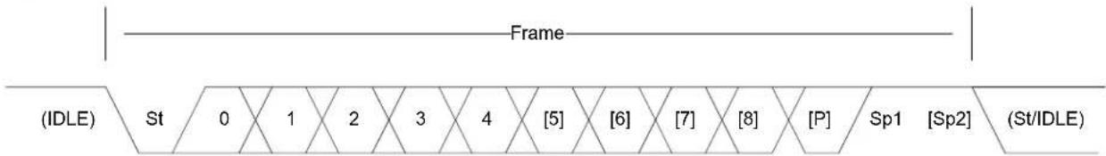
text_image
Frame (IDLE) St 0 1 2 3 4 [5] [6] [7] [8] [P] Sp1 [Sp2] (St/IDLE)15.2.3 Synchronous mode
In synchronous mode a dedicated clock line is provided; either by the USART itself if in master mode, or by an external master if in slave mode. Maximum transmission speed is the same as the GCLK clocking the USART peripheral when in slave mode, and the GCLK divided by two if in master mode. In synchronous mode the interface needs three lines to communicate:
TX (Transmit pin)
RX (Receive pin)
• XCK (Clock pin)
15.2.3.1 Data sampling
In synchronous mode the data is sampled on either the rising or falling edge of the clock signal. This is configured by setting the clock polarity in the configuration struct.
15.2.4 Asynchronous mode
In asynchronous mode no dedicated clock line is used, and the communication is based on matching the clock speed on the transmitter and receiver. The clock is generated from the internal SERCOM baudrate generator, and the frames are synchronized by using the frame start bits. Maximum transmission speed is limited to the SERCOM GCLK divided by 16. In asynchronous mode the interface only needs two lines to communicate:
TX (Transmit pin)
RX (Receive pin)
15.2.4.1 Transmitter/receiver clock matching
For successful transmit and receive using the asynchronous mode the receiver and transmitter clocks needs to be closely matched. When receiving a frame that does not match the selected baud rate closely enough the receiver will be unable to synchronize the frame(s), and garbage transmissions will result.
15.2.5 Parity
Parity can be enabled to detect if a transmission was in error. This is done by counting the number of "1" bits in the frame. When using Even parity the parity bit will be set if the total number of "1"s in the frame are an even number. If using Odd parity the parity bit will be set if the total number of "1"s are Odd.
When receiving a character the receiver will count the number of "1"s in the frame and give an error if the received frame and parity bit disagree.
15.2.6 GPIO configuration
The SERCOM module has four internal pads; the RX pin can be placed freely on any one of the four pads, and the TX and XCK pins have two predefined positions that can be selected as a pair. The pads can then be routed to an external GPIO pin using the normal pin multiplexing scheme on the SAM D20/D21.
15.3 Special Considerations
Never execute large portions of code in the callbacks. These are run from the interrupt routine, and thus having long callbacks will keep the processor in the interrupt handler for an equally long time. A common way to handle this is to use global flags signaling the main application that an interrupt event has happened, and only do the minimal needed processing in the callback.
15.4 Extra Information
For extra information see Extra Information for SERCOM USART Driver. This includes:
- Acronyms
- Dependencies
- Errata
- Module History
15.5 Examples
For a list of examples related to this driver, see Examples for SERCOM USART Driver.
15.6 API Overview
15.6.1 Variable and Type Definitions
15.6.1.1 Type usart_callback_t
typedef void(* usart_callback_t )(const struct usart_module *const module)
Type of the callback functions
15.6.2 Structure Definitions
15.6.2.1 Struct usart_config
Configuration options for USART
Table 15-2. Members
| Type Name Description | ||
| uint32_t baudrate USART baud rate | ||
| enum usart_character_size character_size USART character size | ||
| bool clock_polarity_inverted USART Clock Polarity. If true, data | changes on falling XCK edge and is sampled at rising edge. If false, data changes on rising XCK edge and is sampled at falling edge. | |
| enum usart_dataorder data_order USART bit order (MSB or LSB first) | ||
| uint32_t ext_clock_freq External clock frequency in | synchronous mode. This must be set if use_external_clock is true. | |
| enum gclk_generator generator_source GCLK generator source | ||
| enum usart_signal_mux_settings mux_setting USART pin out | ||
| enum usart_parity parity USART parity | ||
| uint32_t pinmux_pad0 PAD0 pinmux | ||
| uint32_t pinmux_pad1 PAD1 pinmux | ||
| uint32_t pinmux_pad2 PAD2 pinmux | ||
| uint32_t pinmux_pad3 PAD3 pinmux | ||
| bool receiver_enable Enable receiver | ||
| bool run_in_standby If true the USART will be kept | running in Standby sleep mode | |
| enum usart_stopbits stopbits | Number of stop bits | |
| enum usart_transfer_mode | transfer_mode USART in asynchronous or synchronous mode | |
| bool transmitter_enable | Enable transmitter | |
| bool use_external_clock | States whether to use the external clock applied to the XCK pin.In synchronous mode the shift register will act directly on the XCK clock. In asynchronous mode the XCK will be the input to the USART hardware module. | |
15.6.2.2 Struct usart\_module
SERCOM USART driver software instance structure, used to retain software state information of an associated hardware module instance.
Note
The fields of this structure should not be altered by the user application; they are reserved for module-internal use only.
15.6.3 Macro Definitions
15.6.3.1 Macro PINMUX_DEFAULT
#define PINMUX_DEFAULT 0
Default pin mux.
15.6.3.2 Macro PINMUX_UNUSED
#define PINMUX_UNUSED 0xFFFFFFFF
Unused PIN mux.
15.6.3.3 Macro USART\_TIMEOUT
#define USART_TIMEOUT 0xFFFF
USART timeout value.
15.6.4 Function Definitions
15.6.4.1 Lock/Unlock
Function usart\_lock()
Attempt to get lock on driver instance.
enum status_code usart_lock(
struct usart_module *const module)
This function checks the instance's lock, which indicates whether or not it is currently in use, and sets the lock if it was not already set.
The purpose of this is to enable exclusive access to driver instances, so that, e.g., transactions by different services will not interfere with each other.
Table 15-3. Parameters
| Data direction Parameter name Description | |
| [in, out] module Pointer to the driver instance to | lock. |
Table 15-4. Return Values
| Return value Description | |
| STATUS_OK if the module was locked. | |
| STATUS_BUSY if the module was already locked. |
Function usart\_unlock()
Unlock driver instance.
void usart_unlock(
struct usart_module *const module)
This function clears the instance lock, indicating that it is available for use.
Table 15-5. Parameters
| Data direction Parameter name Description | |
| [in, out] module Pointer to the driver instance to | lock. |
15.6.4.2 Writing and reading
Function usart\_write\_wait()
Transmit a character via the USART.
enum status_code usart_write_wait(
struct usart_module *const module,
const uint16_t tx_data)
This blocking function will transmit a single character via the USART.
Table 15-6. Parameters
| Data direction Parameter name Description | |
| [in] module Pointer to the software instance | struct |
| [in] tx_data Data to transfer |
Returns
Status of the operation
Table 15-7. Return Values
| Return value Description | |
| STATUS_OK If the operation was completed | |
| STATUS_BUSY If the operation was not completed, due to the USART module being busy. | |
| STATUS_ERR_DENIED If the transmitter is not enabled | |
Function usart\_read\_wait()
Receive a character via the USART.
enum status_code usart_read_wait(
struct usart_module *const module,
uint16_t *const rx_data)
This blocking function will receive a character via the USART.
Table 15-8. Parameters
| Data direction Parameter name Description | |
| [in] module Pointer to the software instance | struct |
| [out] rx_data Pointer to received data |
Returns
Status of the operation
Table 15-9. Return Values
| Return value Description | |
| STATUS_OK If the operation was completed | |
| STATUS_BUSY If the operation was not completed, due to the USART module being busy | |
| STATUS_ERR_BAD_FORMAT If the operation was not completed, due to configuration mismatch between USART and the sender | |
| STATUS_ERR_BAD_OVERFLOW If the operation was not completed, due to the baud rate being too low or the system frequency being too high | |
| STATUS_ERR_BAD_DATA If the operation was not completed, due to data being corrupted | |
| STATUS_ERR_DENIED If the receiver is not enabled | |
Function usart\_write\_buffer\_wait()
Transmit a buffer of characters via the USART.
enum status_code usart_write_buffer_wait(
struct usart_module *const module,
const uint8_t * tx_data,
uint16_t length)
This blocking function will transmit a block of length characters via the USART
Note
Using this function in combination with the interrupt (_job) functions is not recommended as it has no functionality to check if there is an ongoing interrupt driven operation running or not.
Table 15-10. Parameters
| Data direction Parameter name Description | |
| [in] module Pointer to USART software | instance struct |
| [in] tx_data Pointer to data to transmit | |
| [in] length Number of characters to transmit |
Returns
Status of the operation
Table 15-11. Return Values
| Return value Description | |
| STATUS_OK If operation was completed | |
| STATUS_ERR_INVALID_ARG If operation was not completed, due to invalid arguments | |
| STATUS_ERR_TIMEOUT If operation was not completed, due to USART module timing out | |
| STATUS_ERR_DENIED If the transmitter is not enabled |
Function usart\_read\_buffer\_wait()
Receive a buffer of length characters via the USART.
enum status_code usart_read_buffer_wait(
struct usart_module *const module,
uint8_t * rx_data,
uint16_t length)
This blocking function will receive a block of length characters via the USART.
Note
Using this function in combination with the interrupt (*_job) functions is not recommended as it has no functionality to check if there is an ongoing interrupt driven operation running or not.
Table 15-12. Parameters
| Data direction Parameter name Description | |
| [in] module Pointer to USART software | instance struct |
| [out] rx_data Pointer to receive buffer | |
| [in] length Number of characters to receive |
Returns
Status of the operation.
Table 15-13. Return Values
| Return value Description | |
| STATUS_OK If operation was completed | |
| STATUS_ERR_INVALID_ARG If operation was not completed, due to an invalid argument being supplied | |
| STATUS_ERR_TIMEOUT If operation was not completed, due to USART module timing out | |
| STATUS_ERR_BAD_FORMAT If the operation was not completed, due to a configuration mismatch between USART and the sender | |
| STATUS_ERR_BAD_OVERFLOW If the operation was not completed, due to the baud rate being too low or the system frequency being too high | |
| STATUS_ERR_BAD_DATA | If the operation was not completed, due to data being corrupted |
| STATUS_ERR_DENIED | If the receiver is not enabled |
15.6.4.3 Enabling/Disabling receiver and transmitter
Function usart\_enable\_transceiver()
Enable Transceiver.
void usart_enable_transceiver(
struct usart_module *const module,
enum usart_transceiver_type transceiver_type)
Enable the given transceiver. Either RX or TX.
Table 15-14. Parameters
| Data direction Parameter name Description | |
| [in] module Pointer to USART software | instance struct |
| [in] transceiver_type Transceiver type. |
Function usart\_disable\_transceiver()
Disable Transceiver.
void usart_disable_transceiver(
struct usart_module *const module,
enum usart_transceiver_type transceiver_type)
Disable the given transceiver (RX or TX).
Table 15-15. Parameters
| Data direction Parameter name Description | |
| [in] module Pointer to USART software | instance struct |
| [in] transceiver_type Transceiver type. |
15.6.4.4 Callback Management
Function usart\_register\_callback()
Registers a callback.
void usart_register_callback(
struct usart_module *const module,
usart_callback_t callback_func,
enum usart_callback callback_type)
Registers a callback function which is implemented by the user.
Note
The callback must be enabled by usart_enable_callback, in order for the interrupt handler to call it when the conditions for the callback type are met.
Table 15-16. Parameters
| Data direction Parameter name Description | |
| [in] module Pointer to USART software | instance struct |
| [in] callback_func Pointer to callback function | |
| [in] callback_type Callback type given by an enum |
Function usart\_unregister\_callback()
Unregisters a callback.
void usart_unregister_callback(
struct usart_module * module,
enum usart_callback callback_type)
Unregisters a callback function which is implemented by the user.
Table 15-17. Parameters
| Data direction Parameter name Description | |
| [in, out] module Pointer to USART software | instance struct |
| [in] callback_type Callback type given by an enum |
Function usart\_enable\_callback()
Enables callback.
void usart_enable_callback(
struct usart_module *const module,
enum usart_callback callback_type)
Enables the callback function registered by the usart_register_callback. The callback function will be called from the interrupt handler when the conditions for the callback type are met.
Table 15-18. Parameters
| Data direction Parameter name Description | |
| [in] module Pointer to USART software | instance struct |
| [in] callback_type Callback type given by an enum |
Function usart\_disable\_callback()
Disable callback.
void usart_disable_callback(
struct usart_module *const module,
enum usart_callback callback_type)
Disables the callback function registered by the usart_register_callback, and the callback will not be called from the interrupt routine.
Table 15-19. Parameters
| Data direction Parameter name Description | |
| [in] module Pointer to USART software | instance struct |
| [in] callback_type Callback type given by an enum |
15.6.4.5 Writing and reading
Function usart_write_job()
Asynchronous write a single char.
enum status_code usart_write_job(
struct usart_module *const module,
const uint16_t tx_data)
Sets up the driver to write the data given. If registered and enabled, a callback function will be called when the transmit is completed.
Table 15-20. Parameters
| Data direction Parameter name Description | |
| [in] module Pointer to USART software | instance struct |
| [in] tx_data Data to transfer |
Returns
Status of the operation
Table 15-21. Return Values
| Return value Description | |
| STATUS_OK If operation was completed | |
| STATUS_BUSY If operation was not completed, due to the USART module being busy | |
| STATUS_ERR_DENIED If the transmitter is not enabled |
Function usart\_read\_job()
Asynchronous read a single char.
enum status_code usart_read_job(
struct usart_module *const module,
uint16_t *const rx_data)
Sets up the driver to read data from the USART module to the data pointer given. If registered and enabled, a callback will be called when the receiving is completed.
Table 15-22. Parameters
| Data direction Parameter name Description | |
| [in] module Pointer to USART software | instance struct |
| [out] rx_data Pointer to where received data | should be put |
Returns
Status of the operation
Table 15-23. Return Values
| Return value Description | |
| STATUS_OK If operation was completed |
Return value Description
STATUS_BUSY If operation was not completed,
Function usart\_write\_buffer\_job()
Asynchronous buffer write.
enum status_code usart_write_buffer_job(
struct usart_module *const module,
uint8_t * tx_data,
uint16_t length)
Sets up the driver to write a given buffer over the USART. If registered and enabled, a callback function will be called.
Table 15-24. Parameters
| Data direction Parameter name Description | |
| [in] module Pointer to USART software | instance struct |
| [in] tx_data Pointer do data buffer to transmit | |
| [in] length Length of the data to transmit |
Returns
Status of the operation
Table 15-25. Return Values
| Return value Description | |
| STATUS_OK If operation was completed successfully. | |
| STATUS_BUSY If operation was not completed, due to the USART module being busy | |
| STATUS_ERR_INVALID_ARG If operation was not completed, due to invalid arguments | |
| STATUS_ERR_DENIED If the transmitter is not enabled |
Function usart\_read\_buffer\_job()
Asynchronous buffer read.
enum status_code usart_read_buffer_job(
struct usart_module *const module,
uint8_t * rx_data,
uint16_t length)
Sets up the driver to read from the USART to a given buffer. If registered and enabled, a callback function will be called.
Table 15-26. Parameters
| Data direction Parameter name Description | |
| [in] module Pointer to USART software | instance struct |
| [out] rx_data Pointer to data buffer to receive | |
| [in] length Data buffer length |
Returns
Status of the operation
Table 15-27. Return Values
| Return value Description | |
| STATUS_OK If operation was completed | |
| STATUS_BUSY If operation was not completed, due to the USART module being busy | |
| STATUS_ERR_INVALID_ARG If operation was not completed, due to invalid arguments | |
| STATUS_ERR_DENIED If the transmitter is not enabled | |
Function usart\_abort\_job()
Cancels ongoing read/write operation.
void usart_abort_job(
struct usart_module *const module,
enum usart_transceiver_type transceiver_type)
Cancels the ongoing read/write operation modifying parameters in the USART software struct.
Table 15-28. Parameters
| Data direction Parameter name Description | |
| [in] module Pointer to USART software | instance struct |
| [in] transceiver_type Transfer type to cancel |
Function usart\_get\_job\_status()
Get status from the ongoing or last asynchronous transfer operation.
enum status_code usart_get_job_status(
struct usart_module *const module,
enum usart_transceiver_type transceiver_type)
Returns the error from a given ongoing or last asynchronous transfer operation. Either from a read or write transfer.
Table 15-29. Parameters
| Data direction Parameter name Description | |
| [in] module Pointer to USART software | instance struct |
| [in] transceiver_type Transfer type to check |
Returns
Status of the given job.
Table 15-30. Return Values
| Return value Description | |
| STATUS_OK No error occurred during the last transfer | |
| STATUS_BUSY A transfer is ongoing | |
| STATUS_ERR_BAD_DATA The last operation was aborted due to a parity error. The transfer could be affected by external noise. | |
| STATUS_ERR_BAD_FORMAT The last operation was aborted due to a frame error. | |
| STATUS_ERR_OVERFLOW The last operation was aborted due to a buffer overflow. | |
| STATUS_ERR_INVALID_ARG An invalid transceiver enum given. | |
15.6.4.6 Function usart\_disable()
Disable module.
void usart_disable(
const struct usart_module *const module)
Disables the USART module
Table 15-31. Parameters
| Data direction Parameter name Description | |
| [in] module Pointer to USART software | instance struct |
15.6.4.7 Function usart\_enable()
Enable the module.
void usart_enable(
const struct usart_module *const module)
Enables the USART module
Table 15-32. Parameters
| Data direction Parameter name Description | |
| [in] module Pointer to USART software | instance struct |
15.6.4.8 Function usart\_get\_config\_defaults()
Initializes the device to predefined defaults.
void usart_get_config_defaults(
struct usart_config *const config)
Initialize the USART device to predefined defaults:
• 8-bit asynchronous USART
- No parity
- 1 stop bit
9600 baud
• Transmitter enabled
- Receiver enabled
• GCLK generator 0 as clock source
- Default pin configuration
The configuration struct will be updated with the default configuration.
Table 15-33. Parameters
| Data direction Parameter name Description | |
| [in, out] config Pointer to configuration struct |
15.6.4.9 Function usart\_init()
Initializes the device.
enum status_code usart_init(
struct usart_module *const module,
Sercom *const hw,
const struct usart_config *const config)
Initializes the USART device based on the setting specified in the configuration struct.
Table 15-34. Parameters
| Data direction Parameter name Description | |
| [out] module Pointer to USART device | |
| [in] hw Pointer to USART hardware | instance |
| [in] config Pointer to configuration struct |
Returns
Status of the initialization
Table 15-35. Return Values
| Return value Description | |
| STATUS_OK The initialization was successful | |
| STATUS_BUSY The USART module is busy resetting | |
| STATUS_ERR_DENIED The USART have not been disabled in advance of initialization | |
| STATUS_ERR_INVALID_ARG | The configuration struct contains invalid configuration |
| STATUS_ERR_ALREADY_INITIALIZED The SERCOM | instance has already been initialized with different clock configuration |
| STATUS_ERR_BAUD_UNAVAILABLE The BAUD rate given by the configuration struct cannot be reached with the current clock configuration | |
15.6.4.10 Function usart\_is\_syncing()
Check if peripheral is busy syncing registers across clock domains.
bool usart_is_syncing(
const struct usart_module *const module)
Return peripheral synchronization status. If doing a non-blocking implementation this function can be used to check the sync state and hold of any new actions until sync is complete. If this functions is not run; the functions will block until the sync has completed.
Table 15-36. Parameters
| Data direction Parameter name Description | |
| [in] module Pointer to peripheral module |
Returns
Peripheral sync status
Table 15-37. Return Values
| Return value Description | |
| true Peripheral is busy syncing | |
| false Peripheral is not busy syncing and can be read/written without stalling the bus. | |
15.6.4.11 Function usart\_reset()
Resets the USART module.
void usart_reset(
const struct usart_module *const module)
Disables and resets the USART module.
Table 15-38. Parameters
| Data direction Parameter name Description | |
| [in] module Pointer to the USART software | instance struct |
15.6.5 Enumeration Definitions
15.6.5.1 Enum usart_callback
Callbacks for the Asynchronous USART driver
Table 15-39. Members
| Enum value Description | |
| USART_CALLBACK_BUFFER_TRANSMITTED Callback for buffer transmitted | |
| USART_CALLBACK_BUFFER_RECEIVED Callback for buffer received | |
| USART_CALLBACK_ERROR Callback for error | |
15.6.5.2 Enum usart\_character\_size
Number of bits for the character sent in a frame.
Table 15-40. Members
| Enum value Description | |
| USART_CHARACTER_SIZE_5BIT The char being sent in a frame is 5 bits long | |
| USART_CHARACTER_SIZE_6BIT The char being sent in a frame is 6 bits long | |
| USART_CHARACTER_SIZE_7BIT The char being sent in a frame is 7 bits long | |
| USART_CHARACTER_SIZE_8BIT The char being sent in a frame is 8 bits long | |
| USART_CHARACTER_SIZE_9BIT The char being sent in a frame is 9 bits long | |
15.6.5.3 Enum usart\_dataorder
The data order decides which of MSB or LSB is shifted out first when data is transferred
Table 15-41. Members
| Enum value Description | |
| USART_DATAORDER_MSB The MSB will be shifted out first during transmission, and shifted in first during reception | |
| USART_DATAORDER_LSB The LSB will be shifted out first during transmission, and shifted in first during reception | |
15.6.5.4 Enum usart\_parity
Select parity USART parity mode
Table 15-42. Members
| Enum value Description | |
| USART_PARITY_ODD For odd parity checking, the parity bit will be set if number of ones being transferred is even | |
| USART_PARITY_EVEN For even parity checking, the parity bit will be set if number of ones being received is odd | |
| USART_PARITY_NONE No parity checking will be executed, and there will be no parity bit in the received frame | |
15.6.5.5 Enum usart\_signal\_mux\_settings
Set the functionality of the SERCOM pins.
See SERCOM USART MUX Settings for a description of the various MUX setting options.
Table 15-43. Members
| Enum value Description |
| USART_RX_0_TX_0_XCK_1 MUX setting RX_0_TX_0_XCK_1 |
| USART_RX_0_TX_2_XCK_3 MUX setting RX_0_TX_2_XCK_3 |
| USART_RX_1_TX_0_XCK_1 MUX setting RX_1_TX_0_XCK_1 |
| USART_RX_1_TX_2_XCK_3 MUX setting RX_1_TX_2_XCK_3 |
| USART_RX_2_TX_0_XCK_1 MUX setting RX_2_TX_0_XCK_1 |
| USART_RX_2_TX_2_XCK_3 MUX setting RX_2_TX_2_XCK_3 |
| USART_RX_3_TX_0_XCK_1 MUX setting RX_3_TX_0_XCK_1 |
| USART_RX_3_TX_2_XCK_3 MUX setting RX_3_TX_2_XCK_3 |
15.6.5.6 Enum usart\_stopbits
Number of stop bits for a frame.
Table 15-44. Members
| Enum value Description | |
| USART_STOPBITS_1 Each transferred frame contains 1 stop bit | |
| USART_STOPBITS_2 Each transferred frame contains 2 stop bits | |
15.6.5.7 Enum usart\_transceiver\_type
Select Receiver or Transmitter
Table 15-45. Members
| Enum value Description | |
| USART_TRANSCEIVER_RX The parameter is for the Receiver | |
| USART_TRANSCEIVER_TX The parameter is for the Transmitter | |
15.6.5.8 Enum usart\_transfer\_mode
Select USART transfer mode
Table 15-46. Members
| Enum value Description | |
| USART_TRANSFER_SYNCHRONOUSLY Transfer of data is done synchronously | |
| USART_TRANSFER_ASYNCHRONOUSLY Transfer of data is done asynchronously | |
15.7 SERCOM USART MUX Settings
The following lists the possible internal SERCOM module pad function assignments, for the four SERCOM pads when in USART mode. Note that this is in addition to the physical GPIO pin MUX of the device, and can be used in conjunction to optimize the serial data pin-out.
When TX and RX are connected to the same pin, the USART will operate in half-duplex mode if both the transmitter and receivers are enabled.
Note
When RX and XCK are connected to the same pin, the receiver must not be enabled if the USART is configured to use an external clock.
| Mux/Pad PAD 0 PAD 1 PAD 2 PAD 3 | |||
| RX_0_TX_0_XCK_1 TX / RX XCK -- | |||
| RX_0_TX_2_XCK_3 RX - TX XCK | |||
| RX_1_TX_0_XCK_1 TX RX / XCK -- | |||
| RX_1_TX_2_XCK_3 - RX TX XCK | |||
| RX_2_TX_0_XCK_1 TX XCK RX - | |||
| RX_2_TX_2_XCK_3 -- TX / RX XCK | |||
| RX_3_TX_0_XCK_1 TX XCK - RX | |||
| RX_3_TX_2_XCK_3 -- TX RX / XCK |
15.8 Extra Information for SERCOM USART Driver
15.8.1 Acronyms
Below is a table listing the acronyms used in this module, along with their intended meanings.
| Acronym Description | |
| SERCOM Serial Communication Interface | |
| USART Universal Synchronous and Asynchronous Serial | Receiver and Transmitter |
| LSB | Least Significant Bit |
| MSB | Most Significant Bit |
| DMA | Direct Memory Access |
15.8.2 Dependencies
This driver has the following dependencies:
• System Pin Multiplexer Driver
• System clock configuration
15.8.3 Errata
There are no errata related to this driver.
15.8.4 Module History
An overview of the module history is presented in the table below, with details on the enhancements and fixes made to the module since its first release. The current version of this corresponds to the newest version in the table.
Changelog
Add support for SAMD21 and added new feature as below:
Changelog
- Oversample
• Buffer overflow notification - Irda
- Lin slave
- Start frame detection
- Hardware flow control
-
Collision detection
• DMA support -
Added new transmitter_enable and receiver_enable boolean values to struct usart_config.
- Altered usart_write_* and usart_read_* functions to abort with an error code if the relevant transceiver is not enabled.
- Fixed usart_write_buffer_wait() and usart_read_buffer_wait() not aborting correctly when a timeout condition occurs.
Initial Release
15.9 Examples for SERCOM USART Driver
This is a list of the available Quick Start guides (QSGs) and example applications for SAM D20/D21 Serial USART Driver (SERCOM USART). QSGs are simple examples with step-by-step instructions to configure and use this driver in a selection of use cases. Note that QSGs can be compiled as a standalone application or be added to the user application.
- Quick Start Guide for SERCOM USART - Basic
- Quick Start Guide for SERCOM USART - Callback
- Quick Start Guide for Using DMA with SERCOM USART
15.9.1 Quick Start Guide for SERCOM USART - Basic
This quick start will echo back characters typed into the terminal. In this use case the USART will be configured with the following settings:
- Asynchronous mode
• 9600 Baudrate
• 8-bits, No Parity and 1 Stop Bit
• TX and RX enabled and connected to the Xplained Pro Embedded Debugger virtual COM port
15.9.1.1 Setup
Prerequisites
There are no special setup requirements for this use-case.
Code
Add to the main application source file, outside of any functions:
struct usart_module usart_instance;
Copy-paste the following setup code to your user application:
void configure_usart(void)
{
struct usart_config config_usart;
usart_get_config_defaults(&config_usart);
config_usart.baudrate = 9600;
config_usart.mux_setting = EDBG_CDC_SERCOM_MUX_SETTING;
config_usart.pinmux_pad0 = EDBG_CDC_SERCOM_PINMUX_PAD0;
config_usart.pinmux_pad1 = EDBG_CDC_SERCOM_PINMUX_PAD1;
config_usart.pinmux_pad2 = EDBG_CDC_SERCOM_PINMUX_PAD2;
config_usart.pinmux_pad3 = EDBG_CDC_SERCOM_PINMUX_PAD3;
while (usart_init(&usart_instance,
EDBG_CDC_MODULE, &config_usart) != STATUS_OK) {
}
usart_enable(&usart_instance);
}
Add to user application initialization (typically the start of main()):
configure_usart();
Workflow
- Create a module software instance structure for the USART module to store the USART driver state while it is in use.
struct usart_module usart_instance;
Note
This should never go out of scope as long as the module is in use. In most cases, this should be global.
- Configure the USART module.
a. Create a USART module configuration struct, which can be filled out to adjust the configuration of a physical USART peripheral.
struct usart_config config_usart;
b. Initialize the USART configuration struct with the module's default values.
usart_get_config_defaults(&config_usart);
Note
This should always be performed before using the configuration struct to ensure that all values are initialized to known default settings.
c. Alter the USART settings to configure the physical pinout, baud rate and other relevant parameters.
config_usart.baudrate = 9600;
config_usart.mux_setting = EDBG_CDC_SERCOM_MUX_SETTING;
config_usart.pinmux_pad0 = EDBG_CDC_SERCOM_PINMUX_PAD0;
config_usart.pinmux_pad1 = EDBG_CDC_SERCOM_PINMUX_PAD1;
config_usart.pinmux_pad2 = EDBG_CDC_SERCOM_PINMUX_PAD2;
config_usart.pinmux_pad3 = EDBG_CDC_SERCOM_PINMUX_PAD3;
d. Configure the USART module with the desired settings, retrying while the driver is busy until the configuration is stressfully set.
while (usart_init(&usart_instance,
EDBG_CDC_MODULE, &config_usart) != STATUS_OK) {
}
e. Enable the USART module.
usart_enable(&usart_instance);
15.9.1.2 Use Case
Code
Copy-paste the following code to your user application:
uint8_t string[] = "Hello World!\r\n";
usart_write_buffer_wait(&usart_instance, string, sizeof(string));
uint16_t temp;
while (true) {
if (usart_read_wait(&usart_instance, &temp) == STATUS_OK) {
while (usart_write_wait(&usart_instance, temp) != STATUS_OK) {
}
}
}
Workflow
- Send a string to the USART to show the demo is running, blocking until all characters have been sent.
uint8_t string[] = "Hello World!\r\n";
usart_write_buffer_wait(&usart_instance, string, sizeof(string));
- Enter an infinite loop to continuously echo received values on the USART.
while (true) {
if (usart_read_wait(&usart_instance, &temp) == STATUS_OK) {
while (usart_write_wait(&usart_instance, temp) != STATUS_OK) {
}
}
}
- Perform a blocking read of the USART, storing the received character into the previously declared temporary variable.
if (usart_read_wait(&usart_instance, &temp) == STATUS_OK) {
- Echo the received variable back to the USART via a blocking write.
while (usart_write_wait(&usart_instance, temp) != STATUS_OK) { }
15.9.2 Quick Start Guide for SERCOM USART - Callback
This quick start will echo back characters typed into the terminal, using asynchronous TX and RX callbacks from the USART peripheral. In this use case the USART will be configured with the following settings:
- Asynchronous mode
9600 Baudrate
• 8-bits, No Parity and 1 Stop Bit
• TX and RX enabled and connected to the Xplained Pro Embedded Debugger virtual COM port
15.9.2.1 Setup
Prerequisites
There are no special setup requirements for this use-case.
Code
Add to the main application source file, outside of any functions:
struct usart_module usart_instance;
#define MAX_RX_BUFFER_LENGTH 5
volatile uint8_t rx_buffer[MAX_RX_BUFFER_LENGTH];
Copy-paste the following callback function code to your user application:
void usart_read_callback(const struct usart_module *const usart_module)
{
usart_write_buffer_job(&usart_instance,
(uint8_t *)rx_buffer, MAX_RX_BUFFER_LENGTH);
}
void usart_write_callback(const struct usart_module *const usart_module)
{
port_pin_toggle_output_level(LED_0_PIN);
}
Copy-paste the following setup code to your user application:
void configure_usart(void)
{
struct usart_config config_usart;
usart_get_config_defaults(&config_usart);
config_usart.baudrate = 9600;
config_usart.mux_setting = EDBG_CDC_SERCOM_MUX_SETTING;
config_usart.pinmux_pad0 = EDBG_CDC_SERCOM_PINMUX_PAD0;
config_usart.pinmux_pad1 = EDBG_CDC_SERCOM_PINMUX_PAD1;
config_usart.pinmux_pad2 = EDBG_CDC_SERCOM_PINMUX_PAD2;
config_usart.pinmux_pad3 = EDBG_CDC_SERCOM_PINMUX_PAD3;
while (usart_init(&usart_instance,
EDBG_CDC_MODULE, &config_usart) != STATUS_OK) {
}
usart_enable(&usart_instance);
}
void configure_usart_callbacks(void)
{
usart_register_callback(&usart_instance,
usart_write_callback, USART_CALLBACK_BUFFER_TRANSMITTED);
usart_register_callback(&usart_instance,
usart_read_callback, USART_CALLBACK_BUFFER_RECEIVED);
usart_enable_callback(&usart_instance, USART_CALLBACK_BUFFER_TRANSMITTED);
usart_enable_callback(&usart_instance, USART_CALLBACK_BUFFER_RECEIVED);
}
Add to user application initialization (typically the start of main()):
configure_usart();
configure_usart_callbacks();
Workflow
- Create a module software instance structure for the USART module to store the USART driver state while it is in use.
struct usart_module usart_instance;
Note
This should never go out of scope as long as the module is in use. In most cases, this should be global.
- Configure the USART module.
a. Create a USART module configuration struct, which can be filled out to adjust the configuration of a physical USART peripheral.
struct usart_config config_usart;
b. Initialize the USART configuration struct with the module's default values.
usart_get_config_defaults(&config_usart);
Note
This should always be performed before using the configuration struct to ensure that all values are initialized to known default settings.
c. Alter the USART settings to configure the physical pinout, baud rate and other relevant parameters.
config_usart.baudrate = 9600;
config_usart.mux_setting = EDBG_CDC_SERCOM_MUX_SETTING;
config_usart.pinmux_pad0 = EDBG_CDC_SERCOM_PINMUX_PAD0;
config_usart.pinmux_pad1 = EDBG_CDC_SERCOM_PINMUX_PAD1;
config_usart.pinmux_pad2 = EDBG_CDC_SERCOM_PINMUX_PAD2;
config_usart.pinmux_pad3 = EDBG_CDC_SERCOM_PINMUX_PAD3;
d. Configure the USART module with the desired settings, retrying while the driver is busy until the configuration is stressfully set.
while (usart_init(&usart_instance,
EDBG_CDC_MODULE, &config_usart) != STATUS_OK) {
}
e. Enable the USART module.
usart_enable(&usart_instance);
- Configure the USART callbacks.
a. Register the TX and RX callback functions with the driver.
usart_register_callback(&usart_instance,
usart_write_callback, USART_CALLBACK_BUFFER_TRANSMITTED);
usart_register_callback(&usart_instance,
usart_read_callback, USART_CALLBACK_BUFFER_RECEIVED);
b. Enable the TX and RX callbacks so that they will be called by the driver when appropriate.
usart_enable_callback(&usart_instance, USART_CALLBACK_BUFFER_TRANSMITTED);
usart_enable_callback(&usart_instance, USART_CALLBACK_BUFFER_RECEIVED);
15.9.2.2 Use Case
Code
Copy-paste the following code to your user application:
system_interrupt_enable_global();
uint8_t string[] = "Hello World!\r\n";
usart_write_buffer_job(&usart_instance, string, sizeof(string));
while (true) {
usart_read_buffer_job(&usart_instance,
(uint8_t *)rx_buffer, MAX_RX_BUFFER_LENGTH);
}
Workflow
- Enable global interrupts, so that the callbacks can be fired.
system_interrupt_enable_global();
- Send a string to the USART to show the demo is running, blocking until all characters have been sent.
uint8_t string[] = "Hello World!\r\n";
usart_write_buffer_job(&usart_instance, string, sizeof(string));
- Enter an infinite loop to continuously echo received values on the USART.
while (true) {
- Perform an asynchronous read of the USART, which will fire the registered callback when characters are received.
usart_read_buffer_job(&usart_instance, (uint8_t *)rx_buffer, MAX_RX_BUFFER_LENGTH);
15.9.3 Quick Start Guide for Using DMA with SERCOM USART
The supported device list:
• SAMD21
This quick start will receiving 8 bytes of data from PC terminal and transmit back the string to the terminal through DMA. In this use case the USART will be configured with the following settings:
- Asynchronous mode
• 9600 Baudrate
• 8-bits, No Parity and 1 Stop Bit
• TX and RX enabled and connected to the Xplained Pro Embedded Debugger virtual COM port
15.9.3.1 Setup
Prerequisites
There are no special setup requirements for this use-case.
Code
Add to the main application source file, outside of any functions:
struct usart_module usart_instance;
struct dma_resource usart_dma_resource_rx;
struct dma_resource usart_dma_resource_tx;
#define BUFFER_LEN 8
static uint16_t string[BUFFER_LEN];
COMPILER_ALIGNED(16)
DmacDescriptor example_descriptor_rx;
DmacDescriptor example_descriptor_tx;
Copy-paste the following setup code to your user application:
static void transfer_done_rx( const struct dma_resource* const resource )
{
dma_start_transfer_job(&usart_dma_resource_tx);
}
static void transfer_done_tx( const struct dma_resource* const resource )
{
dma_start_transfer_job(&usart_dma_resource_rx);
}
static void configure_dma_resource_rx(struct dma_resource *resource)
{
struct dma_resource_config config;
dma_get_config_defaults(&config);
config peripheral_trigger = SERCOM3_DMAC_ID_RX;
config trigger_action = DMA_TRIGGER_ACTION_BEAT;
dma_allocate(resource, &config);
}
static void setup_transfer_descriptor_rx(DmacDescriptor *descriptor)
{
struct dma_descriptor_config descriptor_config;
dma_descriptor_get_config_defaults(&descriptor_config);
descriptor_config.beat_size = DMA_BEAT_SIZE_HWORD;
descriptor_config.src_increment_enable = false;
descriptor_config.block_transfer_count = BUFFER_LEN;
descriptor_config.destination_address = (uint32_t)string + sizeof(string);
descriptor_config.source_address = (uint32_t)(&usart_instance.hw->USART.DATA.reg);
dma_descriptor_createubescriptor, &descriptor_config);
}
static void configure_dma_resource_tx(struct dma_resource *resource)
{
struct dma_resource_config config;
dma_get_config_defaults(&config);
config peripheral_trigger = SERCOM3_DMAC_ID_TX;
config trigger_action = DMA_TRIGGER_ACTION_BEAT;
dma_allocate(resource, &config);
}
static void setup_transfer_descriptor_tx(DmacDescriptor *descriptor)
{
struct dma_descriptor_config descriptor_config;
dma_descriptor_get_config_defaults(&descriptor_config);
descriptor_config.beat_size = DMA_BEAT_SIZE_HWORD;
descriptor_config.dst_increment_enable = false;
descriptor_config.block_transfer_count = BUFFER_LEN;
descriptor_config.source_address = (uint32_t)string + sizeof(string);
descriptor_config.destination_address =
(uint32_t)(&usart_instance.hw->USART.DATA.reg);
dma_descriptor_createubescriptor, &descriptor_config);
}
static void configure_usart(void)
{
struct usart_config config_usart;
usart_get_config_defaults(&config_usart);
config_usart.baudrate = 9600;
config_usart.mux_setting = EDBG_CDC_SERCOM_MUX_SETTING;
config_usart.pinmux_pad0 = EDBG_CDC_SERCOM_PINMUX_PAD0;
config_usart.pinmux_pad1 = EDBG_CDC_SERCOM_PINMUX_PAD1;
config_usart.pinmux_pad2 = EDBG_CDC_SERCOM_PINMUX_PAD2;
config_usart.pinmux_pad3 = EDBG_CDC_SERCOM_PINMUX_PAD3;
while (usart_init(&usart_instance,
EDBG_CDC_MODULE, &config_usart) != STATUS_OK) {
}
usart_enable(&usart_instance);
}
Add to user application initialization (typically the start of main()):
configure_usart();
configure_dma_resource_rx(&usart_dma_resource_rx);
configure_dma_resource_tx(&usart_dma_resource_tx);
setup_transfer_descriptor_rx(&example_descriptor_rx);
setup_transfer_descriptor_tx(&example_descriptor_tx);
dma_add_descriptor(&usart_dma_resource_rx, &example_descriptor_rx);
dma_add_descriptor(&usart_dma_resource_tx, &example_descriptor_tx);
dma_register_callback(&usart_dma_resource_rx, transfer_done_rx,
DMA_CALLBACK_TRANSFER_DONE);
dma_register_callback(&usart_dma_resource_tx, transfer_done_tx,
DMA_CALLBACK_TRANSFER_DONE);
dma_enable_callback(&usart_dma_resource_rx,
DMA_CALLBACK_TRANSFER_DONE);
dma_enable_callback(&usart_dma_resource_tx,
DMA_CALLBACK_TRANSFER_DONE);
Workflow
Create variables
- Create a module software instance structure for the USART module to store the USART driver state while it is in use.
struct usart_module usart_instance;
Note
This should never go out of scope as long as the module is in use. In most cases, this should be global.
- Create module software instance structures for DMA resources to store the DMA resource state while it is in use.
struct dma_resource usart_dma_resource_rx;
struct dma_resource usart_dma_resource_tx;
Note
This should never go out of scope as long as the module is in use. In most cases, this should be global.
- Create a buffer to store the data to be transferred /received
#define BUFFER_LEN 8
static uint16_t string[BUFFER_LEN];
- Create DMA transfer descriptors for RX/TX
COMPILER_ALIGNED(16)
DmacDescriptor example_descriptor_rx;
DmacDescriptor example_descriptor_tx;
Configure the USART
- Create a USART module configuration struct, which can be filled out to adjust the configuration of a physical USART peripheral.
struct usart_config config_usart;
- Initialize the USART configuration struct with the module's default values.
usart_get_config_defaults(&config_usart);
Note
This should always be performed before using the configuration struct to ensure that all values are initialized to known default settings.
- Alter the USART settings to configure the physical pinout, baud rate and other relevant parameters.
config_usart.baudrate = 9600;
config_usart.mux_setting = EDBG_CDC_SERCOM_MUX_SETTING;
config_usart.pinmux_pad0 = EDBG_CDC_SERCOM_PINMUX_PAD0;
config_usart.pinmux_pad1 = EDBG_CDC_SERCOM_PINMUX_PAD1;
config_usart.pinmux_pad2 = EDBG_CDC_SERCOM_PINMUX_PAD2;
config_usart.pinmux_pad3 = EDBG_CDC_SERCOM_PINMUX_PAD3;
- Configure the USART module with the desired settings, retrying while the driver is busy until the configuration is stressfully set.
while (usart_init(&usart_instance,
EDBG_CDC_MODULE, &config_usart) != STATUS_OK) {
- Enable the USART module.
usart_enable(&usart_instance);
Configure DMA
- Create a callback function of receiver done
static void transfer_done_rx( const struct dma_resource* const resource )
{
dma_start_transfer_job(&usart_dma_resource_tx);
}
- Create a callback function of transmission done
static void transfer_done_tx( const struct dma_resource* const resource )
{
dma_start_transfer_job(&usart_dma_resource_rx);
}
- Create a DMA resource configuration structure, which can be filled out to adjust the configuration of a single DMA transfer.
struct dma_resource_config config;
- Initialize the DMA resource configuration struct with the module's default values.
dma_get_config_defaults(&config);
Note
This should always be performed before using the configuration struct to ensure that all values are initialized to known default settings.
- Set extra configurations for the DMA resource. It is using peripheral trigger, SERCOM Tx empty trigger and trigger causes a beat transfer in this example.
config.peripheral_trigger = SERCOM3_DMAC_ID_RX;
config trigger_action = DMA_TRIGGER_ACTON_BEAT;
- Allocate a DMA resource with the configurations.
dma_allocate(resource, &config);
- Create a DMA transfer descriptor configuration structure, which can be filled out to adjust the configuration of a single DMA transfer.
struct dma_descriptor_config descriptor_config;
- Initialize the DMA transfer descriptor configuration struct with the module's default values.
dma_descriptor_get_config_defaults(&descriptor_config);
Note
This should always be performed before using the configuration struct to ensure that all values are initialized to known default settings.
- Set the specific parameters for a DMA transfer with transfer size, source address, destination address.
descriptor_config.beat_size = DMA_BEAT_SIZE_HWORD;
descriptor_config.src_increment_enable = false;
descriptor_config.block_transfer_count = BUFFER_LEN;
descriptor_config.destination_address =
(uint32_t)string + sizeof(string);
descriptor_config.source_address =
(uint32_t)(&usart_instance.hw->USART.DATA.reg);
- Create the DMA transfer descriptor.
dma_descriptor_createubescriptor, &descriptor_config);
- Create a DMA resource configuration structure for tx, which can be filled out to adjust the configuration of a single DMA transfer.
struct dma_resource_config config;
- Initialize the DMA resource configuration struct with the module's default values.
dma_get_config_defaults(&config);
Note
This should always be performed before using the configuration struct to ensure that all values are initialized to known default settings.
- Set extra configurations for the DMA resource. It is using peripheral trigger, SERCOM Rx Ready trigger and trigger causes a beat transfer in this example.
config.peripheral_trigger = SERCOM3_DMAC_ID_TX;
config trigger_action = DMA_TRIGGER_ACTON_BEAT;
- Allocate a DMA resource with the configurations.
dma_allocate(resource, &config);
- Create a DMA transfer descriptor configuration structure, which can be filled out to adjust the configuration of a single DMA transfer.
struct dma_descriptor_config descriptor_config;
- Initialize the DMA transfer descriptor configuration struct with the module's default values.
dma_descriptor_get_config_defaults(&descriptor_config);
Note
This should always be performed before using the configuration struct to ensure that all values are initialized to known default settings.
- Set the specific parameters for a DMA transfer with transfer size, source address, destination address.
descriptor_config.beat_size = DMA_BEAT_SIZE_HWORD;
descriptor_config.dst_increment_enable = false;
descriptor_config.block_transfer_count = BUFFER_LEN;
descriptor_config.source_address = (uint32_t)string + sizeof(string);
descriptor_config.destination_address =
(uint32_t)(&usart_instance.hw->USART.DATA.reg);
- Create the DMA transfer descriptor.
dma_descriptor_createubescriptor, &descriptor_config);
15.9.3.2 Use Case
Code
Copy-paste the following code to your user application:
dma_start_transfer_job(&usart_dma_resource_rx);
while (true) {
}
Workflow
- Wait for receiving data.
dma_start_transfer_job(&usart_dma_resource_rx);
- enter endless loop
while (true) {
}
16. SAM D20/D21 System Clock Management Driver (SYSTEM CLOCK)
This driver for SAM D20/D21 devices provides an interface for the configuration and management of the device's clocking related functions. This includes the various clock sources, bus clocks and generic clocks within the device, with functions to manage the enabling, disabling, source selection and prescaling of clocks to various internal peripherals.
The following peripherals are used by this module:
• GCLK (Generic Clock Management)
• PM (Power Management)
• SYSCTRL (Clock Source Control)
The outline of this documentation is as follows:
- Prerequisites
- Module Overview
• Special Considerations - Extra Information
- Examples
- API Overview
16.1 Prerequisites
There are no prerequisites for this module.
16.2 Module Overview
The SAM D20/D21 devices contain a sophisticated clocking system, which is designed to give the maximum flexibility to the user application. This system allows a system designer to tune the performance and power consumption of the device in a dynamic manner, to achieve the best trade-off between the two for a particular application.
This driver provides a set of functions for the configuration and management of the various clock related functionality within the device.
16.2.1 Driver Feature Macro Definition
| Driver Feature Macro Supported devices | |
| FEATURE_SYSTEM_CLOCK_DPLL SAMD21 |
Note
The specific features are only available in the driver when the selected device supports those features.
16.2.2 Clock Sources
The SAM D20/D21 devices have a number of master clock source modules, each of which being capable of producing a stabilized output frequency which can then be fed into the various peripherals and modules within the device.
Possible clock source modules include internal R/C oscillators, internal DFLL modules, as well as external crystal oscillators and/or clock inputs.
16.2.3 CPU / Bus Clocks
The CPU and AHB/APBx buses are clocked by the same physical clock source (referred in this module as the Main Clock), however the APBx buses may have additional prescaler division ratios set to give each peripheral bus a different clock speed.
The general main clock tree for the CPU and associated buses is shown in Figure 16-1: CPU / Bus Clocks on page 401.
Figure 16-1. CPU / Bus Clocks

flowchart
graph TD
A["Clock Sources"] --> B["Main Bus Prescaler"]
B --> C["APBA Bus Prescaler"]
B --> D["APBB Bus Prescaler"]
B --> E["APBC Bus Prescaler"]
C --> F["APBA Bus"]
D --> G["APBB Bus"]
E --> H["APBC Bus"]
I["CPU Bus"] --> B
J["AHB Bus"] --> B
16.2.4 Clock Masking
To save power, the input clock to one or more peripherals on the AHB and APBx busses can be masked away - when masked, no clock is passed into the module. Disabling of clocks of unused modules will prevent all access to the masked module, but will reduce the overall device power consumption.
16.2.5 Generic Clocks
Within the SAM D20/D21 devices are a number of Generic Clocks; these are used to provide clocks to the various peripheral clock domains in the device in a standardized manner. One or more master source clocks can be selected as the input clock to a Generic Clock Generator, which can prescale down the input frequency to a slower rate for use in a peripheral.
Additionally, a number of individually selectable Generic Clock Channels are provided, which multiplex and gate the various generator outputs for one or more peripherals within the device. This setup allows for a single common generator to feed one or more channels, which can then be enabled or disabled individually as required.
Figure 16-2. Generic Clocks

flowchart
graph LR
A["Clock Source a"] --> B["Generator 1"]
B --> C["Channel x"]
B --> D["Channel y"]
C --> E["Peripheral x"]
D --> F["Peripheral y"]
16.2.5.1 Clock Chain Example
An example setup of a complete clock chain within the device is shown in Figure 16-3: Clock Chain Example on page 402.
Figure 16-3. Clock Chain Example
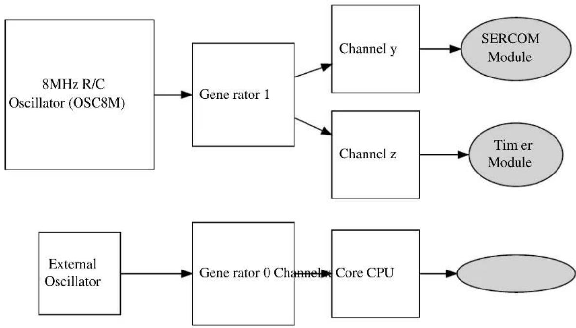
flowchart
graph TD
A["8MHz R/C Oscillator (OSC8M)"] --> B["Gene rator 1"]
B --> C["Channel y"]
B --> D["Channel z"]
C --> E["SERCOM Module"]
D --> F["Timer Module"]
G["External Oscillator"] --> H["Gene rator 0 Channel x Core CPU"]
H --> I["Oval"]
16.2.5.2 Generic Clock Generators
Each Generic Clock generator within the device can source its input clock from one of the provided Source Clocks, and prescale the output for one or more Generic Clock Channels in a one-to-many relationship. The generators thus allow for several clocks to be generated of different frequencies, power usages and accuracies, which can be turned on and off individually to disable the clocks to multiple peripherals as a group.
16.2.5.3 Generic Clock Channels
To connect a Generic Clock Generator to a peripheral within the device, a Generic Clock Channel is used. Each peripheral or peripheral group has an associated Generic Clock Channel, which serves as the clock input for
the peripheral(s). To supply a clock to the peripheral module(s), the associated channel must be connected to a running Generic Clock Generator and the channel enabled.
16.3 Special Considerations
There are no special considerations for this module.
16.4 Extra Information
For extra information see Extra Information for SYSTEM CLOCK Driver. This includes:
- Acronyms
- Dependencies
- Errata
- Module History
16.5 Examples
For a list of examples related to this driver, see Examples for System Clock Driver.
16.6 API Overview
16.6.1 Structure Definitions
16.6.1.1 Struct system_clock_source_dfill_config
DFLL oscillator configuration structure.
Table 16-1. Members
| Type Name Description | ||
| enumsystem_clock_dfill_chill_cycle | chill_cycle Enable Chill Cycle | |
| uint8_t coarse_max_step Coarse adjustment max step size | (Closed loop mode) | |
| uint8_t coarse_value Coarse calibration value (Open | loop mode) | |
| uint16_t fine_max_step Fine adjustment max step size | (Closed loop mode) | |
| uint16_t fine_value Fine calibration value (Open loop | mode) | |
| enumsystem_clock_dfill_loop_mode | loop_mode Loop mode | |
| uint16_t multiply_factor DFLL multiply factor (Closed loop | mode | |
| bool | on_demand | Run On Demand. If this is set the DFLL won't run until requested by a peripheral |
| enumsystem_clock_dfill_quick_lock | quick_lock | Enable Quick Lock |
| enumsystem_clock_dfill_stable_tracking | stable_tracking | DFLL tracking after fine lock |
| enumsystem_clock_dfill_wakeup_lock | wakeup_lock | DFLL lock state on wakeup |
16.6.1.2 Struct system_clock_source_osc32k_config
Internal 32KHz (nominal) oscillator configuration structure.
Table 16-2. Members
| Type Name Description | ||
| bool enable_1khz_output Enable 1kHz output | ||
| bool enable_32khz_output Enable 32kHz output | ||
| bool on_demand Run On Demand. If this is set the | OSC32K won't run until requested by a peripheral | |
| bool run_in_standby Keep the OSC32K enabled in | standby sleep mode | |
| enum system_osc32k_startup startup_time Startup time | ||
| bool write_once Lock configuration after it has been | written, a device reset will release the lock |
16.6.1.3 Struct system_clock_source_osc8m_config
Internal 8MHz (nominal) oscillator configuration structure.
Table 16-3. Members
| Type Name Description | ||
| bool on_demand Run On Demand. If this is set the | OSC8M won't run until requested by a peripheral | |
| enum system_osc8m_div prescaler | ||
| bool run_in_standby Keep the OSC8M enabled in | standby sleep mode | |
16.6.1.4 Struct system_clock_source_xosc32k_config
External 32KHz oscillator clock configuration structure.
Table 16-4. Members
| Type Name Description | ||
| bool auto_gain_control Enable automatic amplitude control | ||
| bool enable_1khz_output Enable 1kHz output | ||
| bool enable_32khz_output Enable 32kHz output | ||
| enum system_clock_external external clock External clock type | ||
| uint32_t | frequency | External clock/crystal frequency |
| bool on_demand Run On Demand. If this is set | the XOSC32K won't run until requested by a peripheral | |
| bool run_in_standby Keep the XOSC32K enabled in | standby sleep mode | |
| enum system_xosc32k_startup startup_time Crystal oscillator start-up time | ||
| bool write_once Lock configuration after it has been | written, a device reset will release the lock | |
16.6.1.5 Struct system\_clock\_source\_xosc\_config
External oscillator clock configuration structure.
Table 16-5. Members
| Type Name Description | ||
| bool auto_gain_control Enable automatic amplitude gain | control | |
| enum system_clock_external external_clock External clock type | ||
| uint32_t frequency External clock/crystal frequency | ||
| bool on_demand Run On Demand. If this is set the | XOSC won't run until requested by a peripheral | |
| bool run_in_standby Keep the XOSC enabled in | standby sleep mode | |
| enum system_xosc_startup startup_time Crystal oscillator start-up time | ||
16.6.1.6 Struct system\_gclk\_chan\_config
Configuration structure for a Generic Clock channel. This structure should be initialized by the system_gclk_chan_get_config_defaults() function before being modified by the user application.
Table 16-6. Members
| Type Name Description | ||
| enum gclk_generator | source_generator | Generic Clock Generator source channel. |
16.6.1.7 Struct system\_gclk\_gen\_config
Configuration structure for a Generic Clock Generator channel. This structure should be initialized by the system_gclk_gen_get_config_defaults() function before being modified by the user application.
Table 16-7. Members
| Type Name Description | ||
| uint32_t division_factor Integer division factor of the clock | output compared to the input. | |
| bool high_when_disabled | If true, the generator output level is high when disabled. | |
| bool output_enable | If true, enables GCLK generator | clock output to a GPIO pin. |
| bool run_in_standby If true, the clock is kept enabled | during device standby mode. | |
Type Name Description
uint8_t source_clock Source clock input channel index.
16.6.2 Function Definitions
16.6.2.1 External Oscillator management
Function system_clock_source_xosc_get_config_defaults()
Retrieve the default configuration for XOSC.
void system_clock_source_xosc_get_config_defaults(
struct system_clock_source_xosc_config *const config)
Fills a configuration structure with the default configuration for an external oscillator module:
- External Crystal
- Start-up time of 16384 external clock cycles
• Automatic crystal gain control mode enabled
• Frequency of 12MHz - Don't run in STANDBY sleep mode
- Run only when requested by peripheral (on demand)
Table 16-8. Parameters
| Data direction Parameter name Description | |
| [out] config Configuration structure to fill with | default values |
Function system\_clock\_source\_xosc\_set\_config()
Configure the external oscillator clock source.
void system_clock_source_xosc_set_config(
struct system_clock_source_xosc_config *const config)
Configures the external oscillator clock source with the given configuration settings.
Table 16-9. Parameters
| Data direction Parameter name Description | |
| [in] config External oscillator configuration | structure containing the new config |
16.6.2.2 External 32KHz Oscillator management
Function system_clock_source_xosc32k_get_config_defaults()
Retrieve the default configuration for XOSC32K.
void system_clock_source_xosc32k_get_config_defaults( struct system_clock_source_xosc32k_config *const config)
Fills a configuration structure with the default configuration for an external 32KHz oscillator module:
- External Crystal
- Start-up time of 16384 external clock cycles
• Automatic crystal gain control mode disabled
• Frequency of 32.768KHz
• 1KHz clock output disabled
• 32KHz clock output enabled - Don't run in STANDBY sleep mode
- Run only when requested by peripheral (on demand)
- Don't lock registers after configuration has been written
Table 16-10. Parameters
| Data direction Parameter name Description | |
| [out] config Configuration structure to fill with | default values |
Function system\_clock\_source\_xosc32k\_set\_config()
Configure the XOSC32K external 32KHz oscillator clock source.
void system_clock_source_xosc32k_set_config(
struct system_clock_source_xosc32k_config *const config)
Configures the external 32KHz oscillator clock source with the given configuration settings.
Table 16-11. Parameters
| Data direction Parameter name Description | |
| [in] config XOSC32K configuration structure | containing the new config |
16.6.2.3 Internal 32KHz Oscillator management
Function system\_clock\_source\_osc32k\_get\_config\_defaults()
Retrieve the default configuration for OSC32K.
void system_clock_source_osc32k_get_config_defaults(
struct system_clock_source_osc32k_config *const config)
Fills a configuration structure with the default configuration for an internal 32KHz oscillator module:
• 1KHz clock output enabled
• 32KHz clock output enabled
- Don't run in STANDBY sleep mode
- Run only when requested by peripheral (on demand)
- Set startup time to 130 cycles
- Don't lock registers after configuration has been written
Table 16-12. Parameters
| Data direction Parameter name Description | |
| [out] config Configuration structure to fill with | default values |
Function system\_clock\_source\_osc32k\_set\_config()
Configure the internal OSC32K oscillator clock source.
void system_clock_source_osc32k_set_config(
struct system_clock_source_osc32k_config *const config)
Configures the 32KHz (nominal) internal RC oscillator with the given configuration settings.
Table 16-13. Parameters
| Data direction Parameter name Description | |
| [in] config OSC32K configuration structure | containing the new config |
16.6.2.4 Internal 8MHz Oscillator management
Function system\_clock\_source\_osc8m\_get\_config\_defaults()
Retrieve the default configuration for OSC8M.
void system_clock_source_osc8m_get_config_defaults(
struct system_clock_source_osc8m_config *const config)
Fills a configuration structure with the default configuration for an internal 8MHz (nominal) oscillator module:
- Clock output frequency divided by a factor of 8
- Don't run in STANDBY sleep mode
- Run only when requested by peripheral (on demand)
Table 16-14. Parameters
| Data direction Parameter name Description | |
| [out] config Configuration structure to fill with | default values |
Function system_clock_source_osc8m_set_config()
Configure the internal OSC8M oscillator clock source.
void system_clock_source_osc8m_set_config(
struct system_clock_source_osc8m_config *const config)
Configures the 8MHz (nominal) internal RC oscillator with the given configuration settings.
Table 16-15. Parameters
| Data direction Parameter name Description | |
| [in] config OSC8M configuration structure | containing the new config |
16.6.2.5 Internal DFLL management
Function system_clock_source_dflI_get_config_defaults()
Retrieve the default configuration for DFLL.
void system_clock_source_dfll_get_config_defaults(
struct system_clock_source_dfll_config *const config)
Fills a configuration structure with the default configuration for a DFLL oscillator module:
- Open loop mode
- QuickLock mode enabled
- Chill cycle enabled
- Output frequency lock maintained during device wake-up
• Continuous tracking of the output frequency - Default tracking values at the mid-points for both coarse and fine tracking parameters
- Don't run in STANDBY sleep mode
- Run only when requested by peripheral (on demand)
Table 16-16. Parameters
| Data direction Parameter name Description | |
| [out] config Configuration structure to fill with | default values |
Function system_clock_source_dfll_set_config()
Configure the DFLL clock source.
void system_clock_source_dfll_set_config(
struct system_clock_source_dfll_config *const config)
Configures the Digital Frequency Locked Loop clock source with the given configuration settings.
Note
The DFLL will be running when this function returns, as the DFLL module needs to be enabled in order to perform the module configuration.
Table 16-17. Parameters
| Data direction Parameter name Description | |
| [in] config DFLL configuration structure | containing the new config |
16.6.2.6 Clock source management
Function system_clock_source_write_calibration()
enum status_code system_clock_source_write_calibration(
const enum system_clock_source system_clock_source,
const uint16_t calibration_value,
const uint8_t freq_range)
Function system_clock_source_enable()
enum status_code system_clock_source_enable( const enum system_clock_source system_clock_source)
Function system_clock_source_disable()
Disables a clock source.
enum status_code system_clock_source_disable(const enum system_clock_source clk_source)
Disables a clock source that was previously enabled.
Table 16-18. Parameters
| Data direction Parameter name Description | |
| [in] clock_source Clock source to disable |
Table 16-19. Return Values
| Return value Description | |
| STATUS_OK Clock source was disabled successfully | |
| STATUS_ERR_INVALID_ARG An invalid or unavailable clock source was given | |
Function system_clock_source_is_ready()
Checks if a clock source is ready.
bool system_clock_source_is_ready(
const enum system_clock_source clk_source)
Checks if a given clock source is ready to be used.
Table 16-20. Parameters
| Data direction Parameter name Description | |
| [in] clock_source Clock source to check if ready |
Returns
Ready state of the given clock source.
Table 16-21. Return Values
| Return value Description | |
| true Clock source is enabled and ready | |
| false Clock source is disabled or not yet ready |
Function system\_clock\_source\_get\_hz()
Retrieve the frequency of a clock source.
uint32_t system_clock_source_get_hz( const enum system_clock_source clk_source)
Determines the current operating frequency of a given clock source.
Table 16-22. Parameters
| Data direction Parameter name Description | |
| [in] clock_source Clock source to get the frequency | of |
Returns
Frequency of the given clock source, in Hz
16.6.2.7 Main clock management
Function system\_main\_clock\_set\_failure\_detect()
Enable or disable the main clock failure detection.
void system_main_clock_set_failure_detect(const bool enable)
This mechanism allows switching automatically the main clock to the safe RCSYS clock, when the main clock source is considered off.
This may happen for instance when an external crystal is selected as the clock source of the main clock and the crystal dies. The mechanism is to detect, during a RCSYS period, at least one rising edge of the main clock. If no rising edge is seen the clock is considered failed. As soon as the detector is enabled, the clock failure detector CFD) will monitor the divided main clock. When a clock failure is detected, the main clock automatically switches to the RCSYS clock and the CFD interrupt is generated if enabled.
Note
The failure detect must be disabled if the system clock is the same or slower than 32kHz as it will believe the system clock has failed with a too-slow clock.
Table 16-23. Parameters
| Data direction Parameter name Description | |
| [in] enable | Boolean true to enable, false to disable detection |
Function system\_cpu\_clock\_set\_divider()
Set main CPU clock divider.
void system_cpu_clock_set_divider( const enum system_main_clock_div divider)
Sets the clock divider used on the main clock to provide the CPU clock.
Table 16-24. Parameters
| Data direction Parameter name Description | |
| [in] divider CPU clock divider to set |
Function system\_cpu\_clock\_get\_hz()
Retrieves the current frequency of the CPU core.
uint32_t system_cpu_clock_get_hz(void)
Retrieves the operating frequency of the CPU core, obtained from the main generic clock and the set CPU bus divider.
Returns
Current CPU frequency in Hz.
Function system\_apb\_clock\_set\_divider()
Set APBx clock divider.
enum status_code system_apb_clock_set_divider( const enum system_clock_apb_bus bus, const enum system_main_clock_div divider)
Set the clock divider used on the main clock to provide the clock for the given APBx bus.
Table 16-25. Parameters
| Data direction Parameter name Description | |
| [in] divider APBx bus divider to set |
Data direction Parameter name Description
[in] bus APBx bus to set divider for
Returns
Status of the clock division change operation.
Table 16-26. Return Values
| Return value Description | |
| STATUS_ERR_INVALID_ARG Invalid bus ID was given | |
| STATUS_OK The APBx clock was set successfully |
Function system\_apb\_clock\_get\_hz()
Retrieves the current frequency of a ABPx.
uint32_t system_apb_clock_get_hz(const enum system_clock_apb_bus bus)
Retrieves the operating frequency of an APBx bus, obtained from the main generic clock and the set APBx bus divider.
Returns
Current APBx bus frequency in Hz.
16.6.2.8 Bus clock masking
Function system\_ahb\_clock\_set\_mask()
Set bits in the clock mask for the AHB bus.
void system_ahb_clock_set_mask(const uint32_t ahb_mask)
This function will set bits in the clock mask for the AHB bus. Any bits set to 1 will enable that clock, 0 bits in the mask will be ignored
Table 16-27. Parameters
| Data direction Parameter name Description | |
| [in] ahb_mask AHB clock mask to enable |
Function system\_ahb\_clock\_clear\_mask()
Clear bits in the clock mask for the AHB bus.
void system_ahb_clock_clear_mask(const uint32_t ahb_mask)
This function will clear bits in the clock mask for the AHB bus. Any bits set to 1 will disable that clock, 0 bits in the mask will be ignored.
Table 16-28. Parameters
| Data direction Parameter name Description | |
| [in] ahb_mask AHB clock mask to disable |
Function system\_apb\_clock\_set\_mask()
Set bits in the clock mask for an APBx bus.
enum status_code system_apb_clock_set_mask( const enum system_clock_apb_bus bus, const uint32_t mask)
This function will set bits in the clock mask for an APBx bus. Any bits set to 1 will enable the corresponding module clock, zero bits in the mask will be ignored.
Table 16-29. Parameters
| Data direction Parameter name Description | |
| [in] mask APBx clock mask, a | |
| SYSTEM_CLOCK_APB_APBx constant from the device header files | |
| [in] bus Bus to set clock mask bits for, | |
| a mask of PM_APBxMASK_* constants from the device header files |
Returns
Status indicating the result of the clock mask change operation.
Table 16-30. Return Values
| Return value Description | |
| STATUS_ERR_INVALID_ARG Invalid bus given | |
| STATUS_OK The clock mask was set successfully |
Function system\_apb\_clock\_clear\_mask()
Clear bits in the clock mask for an APBx bus.
enum status_code system_apb_clock_clear_mask(
const enum system_clock_apb_bus bus,
const uint32_t mask)
This function will clear bits in the clock mask for an APBx bus. Any bits set to 1 will disable the corresponding module clock, zero bits in the mask will be ignored.
Table 16-31. Parameters
| Data direction Parameter name Description | |
| [in] mask APBx clock mask, a | SYSTEM_CLOCK_APB_APBxconstant from the device header files |
| [in] bus Bus to clear clock mask bits for |
Returns
Status indicating the result of the clock mask change operation.
Table 16-32. Return Values
| Return value Description | |
| STATUS_ERR_INVALID_ARG Invalid bus ID was given. | |
| STATUS_OK The clock mask was changed successfully. |
16.6.2.9 System Clock Initialization
Function system\_clock\_init()
Initialize clock system based on the configuration in conf_clocks.h.
void system_clock_init(void)
This function will apply the settings in conf_clocks.h when run from the user application. All clock sources and GCLK generators are running when this function returns.
16.6.2.10 System Flash Wait States
Function system\_flash\_set\_waitstates()
Set flash controller wait states.
void system_flash_set_waitstates(
uint8_t wait_states)
Will set the number of wait states that are used by the onboard flash memory. The number of wait states depend on both device supply voltage and CPU speed. The required number of wait states can be found in the electrical characteristics of the device.
Table 16-33. Parameters
| Data direction Parameter name Description | |
| [in] wait_states Number of wait states to use for | internal flash |
16.6.2.11 Generic Clock management
Function system\_gclk\_is\_syncing()
Determines if the hardware module(s) are currently synchronizing to the bus.
bool system_gclk_is_syncing(void)
Checks to see if the underlying hardware peripheral module(s) are currently synchronizing across multiple clock domains to the hardware bus. This function can be used to delay further operations on a module until such time that it is ready, to prevent blocking delays for synchronization in the user application.
Returns
Synchronization status of the underlying hardware module(s).
Table 16-34. Return Values
| Return value Description | |
| true if the module has completed synchronization | |
| false if the module synchronization is ongoing |
Function system\_gclk\_init()
Initializes the GCLK driver.
void system_gclk_init(void)
Initializes the Generic Clock module, disabling and resetting all active Generic Clock Generators and Channels to their power-on default values.
16.6.2.12 Generic Clock management (Generators)
Function system\_gclk\_gen\_get\_config\_defaults()
Initializes a Generic Clock Generator configuration structure to defaults.
void system_gclk_gen_get_config_defaults(
struct system_gclk_gen_config *const config)
Initializes a given Generic Clock Generator configuration structure to a set of known default values. This function should be called on all new instances of these configuration structures before being modified by the user application.
The default configuration is as follows:
- Clock is generated undivided from the source frequency
- Clock generator output is low when the generator is disabled
• The input clock is sourced from input clock channel 0
• Clock will be disabled during sleep
• The clock output will not be routed to a physical GPIO pin
Table 16-35. Parameters
| Data direction Parameter name Description | |
| [out] config Configuration structure to initialize | to default values |
Function system\_gclk\_gen\_set\_config()
Writes a Generic Clock Generator configuration to the hardware module.
void system_gclk_gen_set_config(
const uint8_t generator,
struct system_gclk_gen_config *const config)
Writes out a given configuration of a Generic Clock Generator configuration to the hardware module.
Note
Changing the clock source on the fly (on a running generator) can take additional time if the clock source is configured to only run on-demand (ONDEMAND bit is set) and it is not currently running (no peripheral is requesting the clock source). In this case the GCLK will request the new clock while still keeping a request to the old clock source until the new clock source is ready.
This function will not start a generator that is not already running; to start the generator, call system_gclk_gen_enable() after configuring a generator.
Table 16-36. Parameters
| Data direction Parameter name Description | |
| [in] generator Generic Clock Generator index to | configure |
| [in] config Configuration settings for the | generator |
Function system\_gclk\_gen\_enable()
Enables a Generic Clock Generator that was previously configured.
void system_gclk_gen_enable(const uint8_t generator)
Starts the clock generation of a Generic Clock Generator that was previously configured via a call to system_gclk_gen_set_config().
Table 16-37. Parameters
| Data direction Parameter name Description | |
| [in] generator Generic Clock Generator index to | enable |
Function system\_gclk\_gen\_disable()
Disables a Generic Clock Generator that was previously enabled.
void system_gclk_gen_disable(const uint8_t generator)
Stops the clock generation of a Generic Clock Generator that was previously started via a call to system_gclk_gen_enable().
Table 16-38. Parameters
| Data direction Parameter name Description | |
| [in] generator Generic Clock Generator index to | disable |
Function system\_gclk\_gen\_is\_enabled()
Determines if the specified Generic Clock Generator is enabled.
bool system_gclk_gen_is_enabled(const uint8_t generator)
Table 16-39. Parameters
| Data direction Parameter name Description | |
| [in] generator Generic Clock Generator index to | check |
Returns
The enabled status.
Table 16-40. Return Values
| Return value Description | |
| true The Generic Clock Generator is enabled; | |
| false The Generic Clock Generator is disabled. |
16.6.2.13 Generic Clock management (Channels)
Function system\_gclk\_chan\_get\_config\_defaults()
Initializes a Generic Clock configuration structure to defaults.
void system_gclk_chan_get_config_defaults(
struct system_gclk_chan_config *const config)
Initializes a given Generic Clock configuration structure to a set of known default values. This function should be called on all new instances of these configuration structures before being modified by the user application.
The default configuration is as follows:
- Clock is sourced from the Generic Clock Generator channel 0
- Clock configuration will not be write-locked when set
Table 16-41. Parameters
| Data direction Parameter name Description | |
| [out] config Configuration structure to initialize | to default values |
Function system\_gclk\_chan\_set\_config()
Writes a Generic Clock configuration to the hardware module.
void system_gclk_chan_set_config(
const uint8_t channel,
struct system_gclk_chan_config *const config)
Writes out a given configuration of a Generic Clock configuration to the hardware module. If the clock is currently running, it will be stopped.
Note
Once called the clock will not be running; to start the clock, call system_gclk_chan_enable() after configuring a clock channel.
Table 16-42. Parameters
| Data direction Parameter name Description | |
| [in] channel Generic Clock channel to configure | |
| [in] config Configuration settings for the clock |
Function system\_gclk\_chan\_enable()
Enables a Generic Clock that was previously configured.
void system_gclk_chan_enable(const uint8_t channel)
Starts the clock generation of a Generic Clock that was previously configured via a call to system_gclk_chan_set_config().
Table 16-43. Parameters
| Data direction Parameter name Description | |
| [in] channel Generic Clock channel to enable |
Function system\_gclk\_chan\_disable()
Disables a Generic Clock that was previously enabled.
void system_gclk_chan_disable(const uint8_t channel)
Stops the clock generation of a Generic Clock that was previously started via a call to system_gclk_chan_enable().
Table 16-44. Parameters
| Data direction Parameter name Description | |
| [in] channel Generic Clock channel to disable |
Function system\_gclk\_chan\_is\_enabled()
Determines if the specified Generic Clock channel is enabled.
bool system_gclk_chan_is_enabled(const uint8_t channel)
Table 16-45. Parameters
| Data direction Parameter name Description | |
| [in] channel Generic Clock Channel index |
Returns
The enabled status.
Table 16-46. Return Values
| Return value Description | |
| true The Generic Clock channel is enabled; | |
| false The Generic Clock channel is disabled. |
Function system\_gclk\_chan\_lock()
Locks a Generic Clock channel from further configuration writes.
void system_gclk_chan_lock(const uint8_t channel)
Locks a generic clock channel from further configuration writes. It is only possible to unlock the channel configuration through a power on reset.
Table 16-47. Parameters
| Data direction Parameter name Description | |
| [in] channel Generic Clock channel to enable |
Function system\_gclk\_chan\_is\_locked()
Determines if the specified Generic Clock channel is locked.
bool system_gclk_chan_is_locked(const uint8_t channel)
Table 16-48. Parameters
| Data direction Parameter name Description | |
| [in] channel Generic Clock Channel index |
Returns
The lock status.
Table 16-49. Return Values
| Return value Description | |
| true The Generic Clock channel is locked; | |
| false The Generic Clock channel is not locked. |
16.6.2.14 Generic Clock frequency retrieval
Function system\_gclk\_gen\_get\_hz()
Retrieves the clock frequency of a Generic Clock generator.
uint32_t system_gclk_gen_get_hz(
const uint8_t generator)
Determines the clock frequency (in Hz) of a specified Generic Clock generator, used as a source to a Generic Clock Channel module.
Table 16-50. Parameters
| Data direction Parameter name Description | |
| [in] generator Generic Clock Generator index |
Returns
The frequency of the generic clock generator, in Hz.
Function system\_gclk\_chan\_get\_hz()
Retrieves the clock frequency of a Generic Clock channel.
uint32_t system_gclk_chan_get_hz(const uint8_t channel)
Determines the clock frequency (in Hz) of a specified Generic Clock channel, used as a source to a device peripheral module.
Table 16-51. Parameters
| Data direction Parameter name Description | |
| [in] channel Generic Clock Channel index |
Returns
The frequency of the generic clock channel, in Hz.
16.6.3 Enumeration Definitions
16.6.3.1 Enum gclk\_generator
List of Available GCLK generators. This enum is used in the peripheral device drivers to select the GCLK generator to be used for its operation.
The number of GCLK generators available is device dependent.
Table 16-52. Members
| Enum value Description | |
| GCLK_GENERATOR_0 GCLK generator channel 0. | |
| GCLK_GENERATOR_1 GCLK generator channel 1. | |
| GCLK_GENERATOR_2 GCLK generator channel 2. | |
| GCLK_GENERATOR_3 GCLK generator channel 3. | |
| GCLK_GENERATOR_4 GCLK generator channel 4. | |
| GCLK_GENERATOR_5 GCLK generator channel 5. | |
| GCLK_GENERATOR_6 GCLK generator channel 6. | |
| GCLK_GENERATOR_7 GCLK generator channel 7. | |
| GCLK_GENERATOR_8 GCLK generator channel 8. | |
| GCLK_GENERATOR_9 GCLK generator channel 9. | |
| GCLK_GENERATOR_10 GCLK generator channel 10. | |
| GCLK_GENERATOR_11 GCLK generator channel 11. | |
| GCLK_GENERATOR_12 GCLK generator channel 12. | |
| GCLK_GENERATOR_13 GCLK generator channel 13. | |
| GCLK_GENERATOR_14 GCLK generator channel 14. | |
| GCLK_GENERATOR_15 GCLK generator channel 15. | |
| GCLK_GENERATOR_16 GCLK generator channel 16. |
16.6.3.2 Enum system\_clock\_apb\_bus
Available bus clock domains on the APB bus.
Table 16-53. Members
| Enum value Description | |
| SYSTEM_CLOCK_APB_APBA Peripheral bus A on the APB bus. | |
| SYSTEM_CLOCK_APB_APBB Peripheral bus B on the APB bus. | |
| SYSTEM_CLOCK_APB_APBC Peripheral bus C on the APB bus. | |
16.6.3.3 Enum system\_clock\_dfl\_chill\_cycle
DFLL chill-cycle behavior modes of the DFLL module. A chill cycle is a period of time when the DFLL output frequency is not measured by the unit, to allow the output to stabilize after a change in the input clock source.
Table 16-54. Members
| Enum value Description | |
| SYSTEM_CLOCK_DFLL_CHILL_CYCLE_ENABLE Enable a chill cycle, where the DFLL output frequency is not measured | |
| SYSTEM_CLOCK_DFLL_CHILL_CYCLE_DISABLE Disable a chill cycle, where the DFLL output frequency is not measured | |
16.6.3.4 Enum system\_clock\_dfill\_loop\_mode
Available operating modes of the DFLL clock source module,
Table 16-55. Members
| Enum value Description | |
| SYSTEM_CLOCK_DFLL_LOOP_MODE_OPEN The DFLL is operating in open loop mode with no feedback | |
| SYSTEM_CLOCK_DFLL_LOOP_MODE_CLOSED The DFLL is operating in closed loop mode with frequency feedback from a low frequency reference clock | |
| SYSTEM_CLOCK_DFLL_LOOP_MODE_USB_RECOVERY The DFLL is operating in USB recovery mode with frequency feedback from USB SOF | |
16.6.3.5 Enum system_clock_dflll_quick_lock
DFLL QuickLock settings for the DFLL module, to allow for a faster lock of the DFLL output frequency at the expense of accuracy.
Table 16-56. Members
| Enum value Description | |
| SYSTEM_CLOCK_DFLL_QUICK_LOCK_ENABLE Enable the | QuickLock feature for looser lock requirements on the DFLL |
| SYSTEM_CLOCK_DFLL_QUICK_LOCK_DISABLE Disable the | QuickLock feature for strict lock requirements on the DFLL |
16.6.3.6 Enum system\_clock\_dfill\_stable\_tracking
DFLL fine tracking behavior modes after a lock has been acquired.
Table 16-57. Members
| Enum value Description | |
| SYSTEM_CLOCK_DFLL_STABLE_TRACKING_TRACK_AFTE | Keep tracking after the DFLL has gotten a fine lock |
| SYSTEM_CLOCK_DFLL_STABLE_TRACKING_FIX_AFTER_L | Stop tracking after the DFLL has gotten a fine lock |
16.6.3.7 Enum system\_clock\_dfill\_wakeup\_lock
DFLL lock behavior modes on device wake-up from sleep.
Table 16-58. Members
| Enum value Description | |
| SYSTEM_CLOCK_DFLL_WAKEUP_LOCK_KEEP Keep DFLL | lock when the device wakes from sleep |
| SYSTEM_CLOCK_DFLL_WAKEUP_LOCK_LOSE Lose DFLL | lock when the devices wakes from sleep |
16.6.3.8 Enum system\_clock\_external
Available external clock source types.
Table 16-59. Members
| Enum value Description | |
| SYSTEM_CLOCK_EXTERNAL_CRYSTAL The external clock source is a crystal oscillator | |
| SYSTEM_CLOCK_EXTERNAL_CLOCK The connected clock source is an external logic level clock signal | |
16.6.3.9 Enum system\_clock\_source
Clock sources available to the GCLK generators
Table 16-60. Members
| Enum value Description | |
| SYSTEM_CLOCK_SOURCE_OSC8M Internal 8MHz RC oscillator | |
| SYSTEM_CLOCK_SOURCE_OSC32K Internal 32kHz RC oscillator | |
| SYSTEM_CLOCK_SOURCE_XOSC External oscillator | |
| SYSTEM_CLOCK_SOURCE_XOSC32K External 32kHz oscillator | |
| SYSTEM_CLOCK_SOURCE_DFLL Digital Frequency Locked Loop (DFLL) | |
| SYSTEM_CLOCK_SOURCE_ULP32K Internal Ultra Low Power 32kHz oscillator | |
16.6.3.10 Enum system\_main\_clock\_div
Available division ratios for the CPU and APB/AHB bus clocks.
Table 16-61. Members
| Enum value Description | |
| SYSTEM_MAIN_CLOCK_DIV_1 Divide Main clock by 1 | |
| SYSTEM_MAIN_CLOCK_DIV_2 Divide Main clock by 2 | |
| SYSTEM_MAIN_CLOCK_DIV_4 Divide Main clock by 4 | |
| SYSTEM_MAIN_CLOCK_DIV_8 Divide Main clock by 8 | |
| SYSTEM_MAIN_CLOCK_DIV_16 Divide Main clock by 16 | |
| SYSTEM_MAIN_CLOCK_DIV_32 Divide Main clock by 32 | |
| SYSTEM_MAIN_CLOCK_DIV_64 Divide Main clock by 64 | |
| SYSTEM_MAIN_CLOCK_DIV_128 Divide Main clock by 128 |
16.6.3.11 Enum system\_osc32k\_startup
Available internal 32KHz oscillator start-up times, as a number of internal OSC32K clock cycles.
Table 16-62. Members
| Enum value Description | |
| SYSTEM_OSC32K_STARTUP_3 Wait 3 clock cycles until the clock source is considered stable | |
| SYSTEM_OSC32K_STARTUP_4 Wait 4 clock cycles until the clock source is considered stable | |
| SYSTEM_OSC32K_STARTUP_6 Wait 6 clock cycles until the clock source is considered stable | |
| SYSTEM_OSC32K_STARTUP_10 Wait 10 clock cycles until the clock source is considered stable | |
| SYSTEM_OSC32K_STARTUP_18 Wait 18 clock cycles until the clock source is considered stable | |
| SYSTEM_OSC32K_STARTUP_34 Wait 34 clock cycles until the clock source is considered stable | |
| SYSTEM_OSC32K_STARTUP_66 Wait 66 clock cycles until the clock source is considered stable | |
Enum value Description
SYSTEM_OSC32K_STARTUP_130 Wait 130 clock cycles until the clock source is considered stable
16.6.3.12 Enum system\_osc8m\_div
Available prescalers for the internal 8MHz (nominal) system clock.
Table 16-63. Members
| Enum value Description | |
| SYSTEM_OSC8M_DIV_1 Do not divide the 8MHz RC oscillator output | |
| SYSTEM_OSC8M_DIV_2 Divide the 8MHz RC oscillator output by 2 | |
| SYSTEM_OSC8M_DIV_4 Divide the 8MHz RC oscillator output by 4 | |
| SYSTEM_OSC8M_DIV_8 Divide the 8MHz RC oscillator output by 8 | |
16.6.3.13 Enum system\_osc8m\_frequency\_range
Internal 8Mhz RC oscillator frequency range setting
Table 16-64. Members
| Enum value Description | |
| SYSTEM_OSC8M_FREQUENCY_RANGE_4_TO_6 Frequency range 4 Mhz to 6 Mhz | |
| SYSTEM_OSC8M_FREQUENCY_RANGE_6_TO_8 Frequency range 6 Mhz to 8 Mhz | |
| SYSTEM_OSC8M_FREQUENCY_RANGE_8_TO_11 Frequency range 8 Mhz to 11 Mhz | |
| SYSTEM_OSC8M_FREQUENCY_RANGE_11_TO_15 Frequency range 11 Mhz to 15 Mhz | |
16.6.3.14 Enum system\_xosc32k\_startup
Available external 32KHz oscillator start-up times, as a number of external clock cycles.
Table 16-65. Members
| Enum value Description | |
| SYSTEM_XOSC32K_STARTUP_0 Wait 0 clock cycles until the clock source is considered stable | |
| SYSTEM_XOSC32K_STARTUP_32 Wait 32 clock cycles until the clock source is considered stable | |
| SYSTEM_XOSC32K_STARTUP_2048 Wait 2048 clock cycles until the clock source is considered stable | |
| SYSTEM_XOSC32K_STARTUP_4096 Wait 4096 clock cycles until the clock source is considered stable | |
| SYSTEM_XOSC32K_STARTUP_16384 Wait 16384 clock cycles until the clock source is considered stable | |
| SYSTEM_XOSC32K_STARTUP_32768 Wait 32768 clock cycles until the clock source is considered stable | |
| SYSTEM_XOSC32K_STARTUP_65536 Wait 65536 clock cycles until the clock source is considered stable | |
Enum value Description
SYSTEM_XOSC32K_STARTUP_131072 Wait 131072 clock cycles until the clock source is considered stable
16.6.3.15 Enum system\_xosc\_startup
Available external oscillator start-up times, as a number of external clock cycles.
Table 16-66. Members
| Enum value Description | |
| SYSTEM_XOSC_STARTUP_1 Wait 1 clock cycles until the clock source is considered stable | |
| SYSTEM_XOSC_STARTUP_2 Wait 2 clock cycles until the clock source is considered stable | |
| SYSTEM_XOSC_STARTUP_4 Wait 4 clock cycles until the clock source is considered stable | |
| SYSTEM_XOSC_STARTUP_8 Wait 8 clock cycles until the clock source is considered stable | |
| SYSTEM_XOSC_STARTUP_16 Wait 16 clock cycles until the clock source is considered stable | |
| SYSTEM_XOSC_STARTUP_32 Wait 32 clock cycles until the clock source is considered stable | |
| SYSTEM_XOSC_STARTUP_64 Wait 64 clock cycles until the clock source is considered stable | |
| SYSTEM_XOSC_STARTUP_128 Wait 128 clock cycles until the clock source is considered stable | |
| SYSTEM_XOSC_STARTUP_256 Wait 256 clock cycles until the clock source is considered stable | |
| SYSTEM_XOSC_STARTUP_512 Wait 512 clock cycles until the clock source is considered stable | |
| SYSTEM_XOSC_STARTUP_1024 Wait 1024 clock cycles until the clock source is considered stable | |
| SYSTEM_XOSC_STARTUP_2048 Wait 2048 clock cycles until the clock source is considered stable | |
| SYSTEM_XOSC_STARTUP_4096 Wait 4096 clock cycles until the clock source is considered stable | |
| SYSTEM_XOSC_STARTUP_8192 Wait 8192 clock cycles until the clock source is considered stable | |
| SYSTEM_XOSC_STARTUP_16384 Wait 16384 clock cycles until the clock source is considered stable | |
| SYSTEM_XOSC_STARTUP_32768 Wait 32768 clock cycles until the clock source is considered stable | |
16.7 Extra Information for SYSTEM CLOCK Driver
16.7.1 Acronyms
Below is a table listing the acronyms used in this module, along with their intended meanings.
| Acronym Description | |
| DFLL Digital Frequency Locked Loop | |
| MUX Multiplexer | |
| OSC32K Internal 32KHz Oscillator | |
| OSC8M Internal 8MHz Oscillator | |
| PLL Phase Locked Loop | |
| OSC Oscillator | |
| XOSC External Oscillator | |
| XOSC32K External 32KHz Oscillator | |
| AHB Advanced High-performance Bus | |
| APB Advanced Peripheral Bus | |
| DPLL Digital Phase Locked Loop |
16.7.2 Dependencies
This driver has the following dependencies:
None
16.7.3 Errata
• This driver implements workaround for errata 10558
"Several reset values of SYSCTRL.INTFLAG are wrong (BOD and DFLL)" When system_init is called it will reset these interrupts flags before they are used.
• This driver implements experimental workaround for errata 9905
"The DFLL clock must be requested before being configured otherwise a write access to a DFLL register can freeze the device." This driver will enable and configure the DFLL before the ONDEMAND bit is set.
16.7.4 Module History
An overview of the module history is presented in the table below, with details on the enhancements and fixes made to the module since its first release. The current version of this corresponds to the newest version in the table.
Changelog
- Corrected OSC32K startup time definitions.
- Support locking of OSC32K and XOSC32K config register (default: false).
- Added DPLL support, functions added: system_clock_source_dpll_get_config_defaults() and system_clock_source_dpll_set_config().
- Moved gclk channel locking feature out of the config struct, functions added: system_gclk_chan_lock(), system_gclk_chan_is_locked(), system_gclk_chan_is_enabled() and system_gclk_gen_is_enabled().
Fixed system_gclk_chan_disable() deadlocking if a channel is enabled and configured to a failed/not running clock generator. - Changed default value for CONF_CLOCK_DFLL_ON_DEMAND from true to false.
- Fixed system_flash_set_waitstates() failing with an assertion if an odd number of wait states provided.
- Updated dfll configuration function to implement workaround for errata 9905 in the DFLL module.
Changelog
- Updated system_clock_init() to reset interrupt flags before they are used, errata 10558.
- Fixed system_clock_source_get_hz() to return correcy DFLL frequency number.
- Fixed system_clock_source_is_ready not returning the correct state for SYSTEM_CLOCK_SOURCE_OSC8M.
- Renamed the various system_clock_source_*_get_default_config() functions to system_clock_source_*_get_config_defaults() to match the remainder of ASF.
- Added OSC8M calibration constant loading from the device signature row when the oscillator is initialized.
- Updated default configuration of the XOSC32 to disable Automatic Gain Control due to silicon errata.
Initial Release
16.8 Examples for System Clock Driver
This is a list of the available Quick Start guides (QSGs) and example applications for SAM D20/D21 System Clock Management Driver (SYSTEM CLOCK). QSGs are simple examples with step-by-step instructions to configure and use this driver in a selection of use cases. Note that QSGs can be compiled as a standalone application or be added to the user application.
- Quick Start Guide for SYSTEM CLOCK - Basic
- Quick Start Guide for SYSTEM CLOCK - GCLK Configuration
16.8.1 Quick Start Guide for SYSTEM CLOCK - Basic
In this case we apply the following configuration:
• RC8MHz (internal 8MHz RC oscillator)
- Divide by 4, giving a frequency of 2MHz
• DFLL (Digital frequency locked loop)
- Open loop mode
- 48MHz frequency
- CPU clock
- Use two wait states when reading from flash memory
- Use the DFLL, configured to 48MHz
16.8.1.1 Setup
Prerequisites
There are no special setup requirements for this use-case.
Code
Copy-paste the following setup code to your application:
void configure_extosc32k(void)
{
struct system_clock_source_xosc32k_config config_ext32k;
system_clock_source_xosc32k_get_config_defaults(&config_ext32k);
config_ext32k.startup_time = SYSTEM_XOSC32K_STARTUP_4096;
system_clock_source_xosc32k_set_config(&config_ext32k);
}
void configure_dfll_open_loop(void)
{
struct system_clock_source_dfll_config config_dfll;
system_clock_source_dfll_get_config_defaults(&config_dfll);
system_clock_source_dfll_set_config(&config_dfll);
}
Workflow
- Create a EXTOSC32K module configuration struct, which can be filled out to adjust the configuration of the external 32KHz oscillator channel.
struct system_clock_source_xosc32k_config config_ext32k;
- Initialize the oscillator configuration struct with the module's default values.
system_clock_source_xosc32k_get_config_defaults(&config_ext32k);
Note
This should always be performed before using the configuration struct to ensure that all values are initialized to known default settings.
- Alter the EXTOSC32K module configuration struct to require a start-up time of 4096 clock cycles.
config_ext32k.startup_time = SYSTEM_XOSC32K_STARTUP_4096;
- Write the new configuration to the EXTOSC32K module.
system_clock_source_xosc32k_set_config(&config_ext32k);
- Create a DFLL module configuration struct, which can be filled out to adjust the configuration of the external 32KHz oscillator channel.
struct system_clock_source_dfll_config config_dfll;
- Initialize the DFLL oscillator configuration struct with the module's default values.
system_clock_source_dfl1_get_config_defaults(&config_dfl1);
Note
This should always be performed before using the configuration struct to ensure that all values are initialized to known default settings.
- Write the new configuration to the DFLL module.
system_clock_source_dfll_set_config(&config_dfll);
Code
Copy-paste the following code to your user application:
/* Configure the external 32KHz oscillator */
configure_extosc32k();
/* Enable the external 32KHz oscillator */
enum status_code osc32k_status =
system_clock_source_enable(SYSTEM_CLOCK_SOURCE_XOSC32K);
if (osc32k_status != STATUS_OK) {
/* Error enabling the clock source */
}
/* Configure the DFLL in open loop mode using default values */
configure_dfll_open_loop();
/* Enable the DFLL oscillator */
enum status_code dfll_status =
system_clock_source_enable(SYSTEM_CLOCK_SOURCE_DFLL);
if (dfll_status != STATUS_OK) {
/* Error enabling the clock source */
}
/* Configure flash wait states before switching to high frequency clock */
system_flash_set_waitstates(2);
/* Change system clock to DFLL */
struct system_gclk_gen_config config_gclock_gen;
system_gclk_gen_get_config_defaults(&config_gclock_gen);
config_gclock_gen.source_clock = SYSTEM_CLOCK_SOURCE_DFLL;
config_gclock_gen.division_factor = 1;
system_gclk_gen_set_config(GCLK_GENERATOR_0, &config_gclock_gen);
Workflow
- Configure the external 32KHz oscillator source using the previously defined setup function.
configure_extosc32k();
- Enable the configured external 32KHz oscillator source.
enum status_code osc32k_status =
system_clock_source_enable(SYSTEM_CLOCK_SOURCE_XOSC32K);
if (osc32k_status != STATUS_OK) {
/* Error enabling the clock source */
}
- Configure the DFLL oscillator source using the previously defined setup function.
configure_dfl1_open_loop();
- Enable the configured DFLL oscillator source.
enum status_code dfll_status =
system_clock_source_enable(SYSTEM_CLOCK_SOURCE_DFLL);
if (dfll_status != STATUS_OK) {
/* Error enabling the clock source */
}
- Configure the flash wait states to have two wait states per read, as the high speed DFLL will be used as the system clock. If insufficient wait states are used, the device may crash randomly due to misread instructions.
system_flash_set_waitstates(2);
- Switch the system clock source to the DFLL, by reconfiguring the main clock generator.
struct system_gclk_gen_config config_gclock_gen;
system_gclk_gen_get_config_defaults(&config_gclock_gen);
config_gclock_gen.source_clock = SYSTEM_CLOCK_SOURCE_DFLL;
config_gclock_gen.division_factor = 1;
system_gclk_gen_set_config(GCLK_GENERATOR_0, &config_gclock_gen);
16.8.2 Quick Start Guide for SYSTEM CLOCK - GCLK Configuration
In this use case, the GCLK module is configured for:
• One generator attached to the internal 8MHz RC oscillator clock source
- Generator output equal to input frequency divided by a factor of 128
• One channel (connected to the TC0 module) enabled with the enabled generator selected
This use case configures a clock channel to output a clock for a peripheral within the device, by first setting up a clock generator from a master clock source, and then linking the generator to the desired channel. This clock can then be used to clock a module within the device.
16.8.2.1 Setup
Prerequisites
There are no special setup requirements for this use-case.
Code
Copy-paste the following setup code to your user application:
void configure_gclock_generator(void)
{
struct system_gclk_gen_config gclock_gen_conf;
system_gclk_gen_get_config_defaults(&gclock_gen_conf);
gclock_gen_conf.source_clock = SYSTEM_CLOCK_SOURCE_OSC8M;
gclock_gen_conf.division_factor = 128;
system_gclk_gen_set_config(GCLK_GENERATOR_1, &gclock_gen_conf);
system_gclk_gen_enable(GCLK_GENERATOR_1);
}
void configure_gclock_channel(void)
{
struct system_gclk_chan_config gclk_chan_conf;
system_gclk_chan_get_config_defaults(&gclk_chan_conf);
gclk_chan_conf.source_generator = GCLK_GENERATOR_1;
system_gclk_chan_set_config(TC3_GCLK_ID, &gclk_chan_conf);
system_gclk_chan_enable(TC3_GCLK_ID);
}
Add to user application initialization (typically the start of main()):
configure_gclock_generator();
configure_gclock_channel();
Workflow
- Create a GCLK generator configuration struct, which can be filled out to adjust the configuration of a single clock generator.
struct system_gclk_gen_config gclock_gen_conf;
- Initialize the generator configuration struct with the module's default values.
system_gclk_gen_get_config_defaults(&gclock_gen_conf);
Note
This should always be performed before using the configuration struct to ensure that all values are initialized to known default settings.
- Adjust the configuration struct to request that the master clock source channel 0 be used as the source of the generator, and set the generator output prescaler to divide the input clock by a factor of 128.
gclock_gen_conf.source_clock = SYSTEM_CLOCK_SOURCE_OSC8M;
gclock_gen_conf.division_factor = 128;
- Configure the generator using the configuration structure.
system_gclk_gen_set_config(GCLK_GENERATOR_1, &gclock_gen_conf);
Note
The existing configuration struct may be re-used, as long as any values that have been altered from the default settings are taken into account by the user application.
- Enable the generator once it has been properly configured, to begin clock generation.
system_gclk_gen_enable(GCLK_GENERATOR_1);
- Create a GCLK channel configuration struct, which can be filled out to adjust the configuration of a single generic clock channel.
struct system_gclk_chan_config gclk_chan_conf;
- Initialize the channel configuration struct with the module's default values.
system_gclk_chan_get_config_defaults(&gclk_chan_conf);
Note
This should always be performed before using the configuration struct to ensure that all values are initialized to known default settings.
- Adjust the configuration struct to request that the previously configured and enabled clock generator be used as the clock source for the channel.
gclk_chan_conf.source_generator = GCLK_GENERATOR_1;
- Configure the channel using the configuration structure.
system_gclk_chan_set_config(TC3_GCLK_ID, &gclk_chan_conf);
Note
The existing configuration struct may be re-used, as long as any values that have been altered from the default settings are taken into account by the user application.
- Enable the channel once it has been properly configured, to output the clock to the channel's peripheral module consumers.
system_gclk_chan_enable(TC3_GCLK_ID);
16.8.2.2 Use Case
Code
Copy-paste the following code to your user application:
while (true) {
/* Nothing to do */
}
Workflow
- As the clock is generated asynchronously to the system core, no special extra application code is required.
17. SAM D20/D21 System Driver (SYSTEM)
This driver for SAM D20/D21 devices provides an interface for the configuration and management of the device's system relation functionality, necessary for the basic device operation. This is not limited to a single peripheral, but extends across multiple hardware peripherals,
The following peripherals are used by this module:
• SYSCTRL (System Control)
• PM (Power Manager)
The outline of this documentation is as follows:
- Prerequisites
- Module Overview
• Special Considerations - Extra Information
- Examples
- API Overview
17.1 Prerequisites
There are no prerequisites for this module.
17.2 Module Overview
The System driver provides a collection of interfaces between the user application logic, and the core device functionality (such as clocks, reset cause determination, etc.) that is required for all applications. It contains a number of sub-modules that control one specific aspect of the device:
• System Core (this module)
• System Clock Control (sub-module)
• System Interrupt Control (sub-module)
• System Pin Multiplexer Control (sub-module)
17.2.1 Voltage References
The various analog modules within the SAM D20/D21 devices (such as AC, ADC and DAC) require a voltage reference to be configured to act as a reference point for comparisons and conversions.
The SAM D20/D21 devices contain multiple references, including an internal temperature sensor, and a fixed bandgap voltage source. When enabled, the associated voltage reference can be selected within the desired peripheral where applicable.
17.2.2 System Reset Cause
In some application there may be a need to execute a different program flow based on how the device was reset. For example, if the cause of reset was the Watchdog timer (WDT), this might indicate an error in the application and a form of error handling or error logging might be needed.
For this reason, an API is provided to retrieve the cause of the last system reset, so that appropriate action can be taken.
17.2.3 Sleep Modes
The SAM D20/D21 devices have several sleep modes, where the sleep mode controls which clock systems on the device will remain enabled or disabled when the device enters a low power sleep mode. Table 17-1: SAM D20/D21 Device Sleep Modes on page 435 lists the clock settings of the different sleep modes.
Table 17-1. SAM D20/D21 Device Sleep Modes
| Sleep mode | CPU clock | AHB clock | APB clocks | Clock sources | System clock | 32KHz Reg | mode | RAM mode |
| IDLE 0 Stop Run Run Run Run Normal Normal | ||||||||
| IDLE 1 Stop Stop Run Run Run Normal Normal | ||||||||
| IDLE 2 Stop Stop Stop Run Run Run Normal Normal | ||||||||
| STANDBY Stop Stop Stop Stop Stop Low | Power | Source/Drain biasing | ||||||
To enter device sleep, one of the available sleep modes must be set, and the function to enter sleep called. The device will automatically wake up in response to an interrupt being generated or other device event.
Some peripheral clocks will remain enabled during sleep, depending on their configuration; if desired, modules can remain clocked during sleep to allow them to continue to operate while other parts of the system are powered down to save power.
17.3 Special Considerations
Most of the functions in this driver have device specific restrictions and caveats; refer to your device datasheet.
17.4 Extra Information
For extra information see Extra Information for SYSTEM Driver. This includes:
- Acronyms
- Dependencies
- Errata
- Module History
17.5 Examples
For SYSTEM module related examples, please refer to the sub-modules listed in the system module overview.
17.6 API Overview
17.6.1 Function Definitions
17.6.1.1 System identification
Function system_get_device_id()
Retrieve the device identification signature.
uint32_t system_get_device_id(void)
Retrieves the signature of the current device.
17.6.1.2 Voltage references
Function system\_voltage\_reference\_enable()
Enable the selected voltage reference.
void system_voltage_reference_enable( const enum system_voltage_reference vref)
Enables the selected voltage reference source, making the voltage reference available on a pin as well as an input source to the analog peripherals.
Table 17-2. Parameters
| Data direction Parameter name Description | |
| [in] vref Voltage reference to enable |
Function system\_voltage\_reference\_disable()
Disable the selected voltage reference.
void system_voltage_reference_disable( const enum system_voltage_reference vref)
Disables the selected voltage reference source.
Table 17-3. Parameters
| Data direction Parameter name Description | |
| [in] vref Voltage reference to disable |
17.6.1.3 Device sleep
Function system\_set\_sleepmode()
Set the sleep mode of the device.
enum status_code system_set_sleepmode( const enum system_sleepmode sleep_mode)
Sets the sleep mode of the device; the configured sleep mode will be entered upon the next call of the system_sleep() function.
For an overview of which systems are disabled in sleep for the different sleep modes, see Sleep Modes.
Table 17-4. Parameters
| Data direction Parameter name Description | |
| [in] sleep_mode Sleep mode to configure for the | next sleep operation |
Table 17-5. Return Values
| Return value Description | |
| STATUS_OK Operation completed successfully | |
| STATUS_ERR_INVALID_ARG The requested sleep mode was invalid or not available | |
Function system\_sleep()
Put the system to sleep waiting for interrupt.
void system_sleep(void)
Executes a device DSB (Data Synchronization Barrier) instruction to ensure all ongoing memory accesses have completed, then a WFI (Wait For Interrupt) instruction to place the device into the sleep mode specified by system_set_sleepmode until woken by an interrupt.
17.6.1.4 Reset control
Function system\_is\_debugger\_present()
Check if bugger is present.
bool system_is_debugger_present(void)
Check if debugger is connected to the onboard debug system (DAP)
Returns
A bool identifying if a debugger is present
Table 17-6. Return Values
| Return value Description | |
| true Debugger is connected to the system | |
| false Debugger is not connected to the system |
Function system\_reset()
Reset the MCU.
void system_reset(void)
Resets the MCU and all associated peripherals and registers, except RTC, all 32kHz sources, WDT (if ALWAYSON is set) and GCLK (if WRTLOCK is set).
Function system\_get\_reset\_cause()
Return the reset cause.
enum system_reset_cause system_get_reset_cause(void)
Retrieves the cause of the last system reset.
Returns
An enum value indicating the cause of the last system reset.
17.6.1.5 System initialization
Function system\_init()
Initialize system.
void system_init(void)
This function will call the various initialization functions within the system namespace. If a given optional system module is not available, the associated call will effectively be a NOP (No Operation).
Currently the following initialization functions are supported:
- System clock initialization (via the SYSTEM CLOCK sub-module)
• Board hardware initialization (via the Board module)
• Event system driver initialization (via the EVSYS module)
• External Interrupt driver initialization (via the EXTINT module)
17.6.2 Enumeration Definitions
17.6.2.1 Enum system\_reset\_cause
List of possible reset causes of the system.
Table 17-7. Members
| Enum value Description | |
| SYSTEM_RESET_CAUSE_SOFTWARE The system was last reset by a software reset. | |
| SYSTEM_RESET_CAUSE_WDT The system was last reset by the watchdog timer. | |
| SYSTEM_RESET_CAUSE_EXTERNAL_RESET The system was last reset because the external reset line was pulled low. | |
| SYSTEM_RESET_CAUSE_BOD33 The system was last reset by the BOD33. | |
| SYSTEM_RESET_CAUSE_BOD12 The system was last reset by the BOD12. | |
| SYSTEM_RESET_CAUSE_POR The system was last reset by the POR (Power on reset). | |
17.6.2.2 Enum system\_sleepmode
List of available sleep modes in the device. A table of clocks available in different sleep modes can be found in Sleep Modes.
Table 17-8. Members
| Enum value Description | |
| SYSTEM_SLEEPMODE_IDLE_0 IDLE 0 sleep mode. | |
| SYSTEM_SLEEPMODE_IDLE_1 IDLE 1 sleep mode. | |
| SYSTEM_SLEEPMODE_IDLE_2 IDLE 2 sleep mode. | |
| SYSTEM_SLEEPMODE_STANDBY Standby sleep mode. |
17.6.2.3 Enum system\_voltage\_reference
List of available voltage references (VREF) that may be used within the device.
Table 17-9. Members
| Enum value Description | |
| SYSTEM_VOLTAGE_REFERENCE_TEMPSENSE Temperature sensor voltage reference. | |
| SYSTEM_VOLTAGE_REFERENCE_BANDGAP Bandgap voltage reference. | |
17.7 Extra Information for SYSTEM Driver
17.7.1 Acronyms
Below is a table listing the acronyms used in this module, along with their intended meanings.
| Acronym Definition | |
| PM Power Manager | |
| SYSCTRL System control interface |
17.7.2 Dependencies
This driver has the following dependencies:
None
17.7.3 Errata
There are no errata related to this driver.
17.7.4 Module History
An overview of the module history is presented in the table below, with details on the enhancements and fixes made to the module since its first release. The current version of this corresponds to the newest version in the table.
| Changelog |
| Added support for SAMD21 |
| Added new system_reset() to reset the complete MCU with some exceptions |
| Added new system_get_device_id() function to retrieved the device ID. |
| Initial Release |
18. SAM D20/D21 System Interrupt Driver (SYSTEM INTERRUPT)
This driver for SAM D20/D21 devices provides an interface for the configuration and management of internal software and hardware interrupts/exceptions.
The following peripherals are used by this module:
• NVIC (Nested Vector Interrupt Controller)
The outline of this documentation is as follows:
- Prerequisites
- Module Overview
• Special Considerations
- Extra Information
- Examples
- API Overview
18.1 Prerequisites
There are no prerequisites for this module.
18.2 Module Overview
The ARM ^® Cortex ^® M0+ core contains an interrupt an exception vector table, which can be used to configure the device's interrupt handlers; individual interrupts and exceptions can be enabled and disabled, as well as configured with a variable priority.
This driver provides a set of wrappers around the core interrupt functions, to expose a simple API for the management of global and individual interrupts within the device.
18.2.1 Critical Sections
In some applications it is important to ensure that no interrupts may be executed by the system whilst a critical portion of code is being run; for example, a buffer may be copied from one context to another - during which interrupts must be disabled to avoid corruption of the source buffer contents until the copy has completed. This driver provides a basic API to enter and exit nested critical sections, so that global interrupts can be kept disabled for as long as necessary to complete a critical application code section.
18.2.2 Software Interrupts
For some applications, it may be desirable to raise a module or core interrupt via software. For this reason, a set of APIs to set an interrupt or exception as pending are provided to the user application.
18.3 Special Considerations
Interrupts from peripherals in the SAM D20/D21 devices are on a per-module basis; an interrupt raised from any source within a module will cause a single, module-common handler to execute. It is the user application or driver's responsibility to de-multiplex the module-common interrupt to determine the exact interrupt cause.
18.4 Extra Information
For extra information see Extra Information for SYSTEM INTERRUPT Driver. This includes:
- Acronyms
- Dependencies
- Errata
- Module History
18.5 Examples
For a list of examples related to this driver, see Examples for SYSTEM INTERRUPT Driver.
18.6 API Overview
18.6.1 Function Definitions
18.6.1.1 Critical Section Management
Function system_interrupt_enter_critical_section()
Enters a critical section.
void system_interrupt_enter_critical_section(void)
Disables global interrupts. To support nested critical sections, an internal count of the critical section nesting will be kept, so that global interrupts are only re-enabled upon leaving the outermost nested critical section.
Function system\_interrupt\_leave\_critical\_section()
Leaves a critical section.
void system_interrupt_leave_critical_section(void)
Enables global interrupts. To support nested critical sections, an internal count of the critical section nesting will be kept, so that global interrupts are only re-enabled upon leaving the outermost nested critical section.
18.6.1.2 Interrupt Enabling/Disabling
Function system_interrupt_is_global_enabled()
Check if global interrupts are enabled.
bool system_interrupt_is_global_enabled(void)
Checks if global interrupts are currently enabled.
Returns
A boolean that identifies if the global interrupts are enabled or not.
Table 18-1. Return Values
| Return value Description | |
| true Global interrupts are currently enabled | |
| false Global interrupts are currently disabled |
Function system\_interrupt\_enable\_global()
Enables global interrupts.
void system_interrupt_enable_global(void)
Enables global interrupts in the device to fire any enabled interrupt handlers.
Function system\_interrupt\_disable\_global()
Disables global interrupts.
void system_interrupt_disable_global(void)
Disabled global interrupts in the device, preventing any enabled interrupt handlers from executing.
Function system\_interrupt\_is\_enabled()
Checks if an interrupt vector is enabled or not.
bool system_interrupt_is_enabled( const enum system_interrupt_vector vector)
Checks if a specific interrupt vector is currently enabled.
Table 18-2. Parameters
| Data direction Parameter name Description | |
| [in] vector Interrupt vector number to check |
Returns
A variable identifying if the requested interrupt vector is enabled
Table 18-3. Return Values
| Return value Description | |
| true Specified interrupt vector is currently enabled | |
| false Specified interrupt vector is currently disabled |
Function system\_interrupt\_enable()
Enable interrupt vector.
void system_interrupt_enable(
const enum system_interrupt_vector vector)
Enables execution of the software handler for the requested interrupt vector.
Table 18-4. Parameters
| Data direction Parameter name Description | |
| [in] vector Interrupt vector to enable |
Function system\_interrupt\_disable()
Disable interrupt vector.
void system_interrupt_disable(
const enum system_interrupt_vector vector)
Disables execution of the software handler for the requested interrupt vector.
Table 18-5. Parameters
| Data direction Parameter name Description | |
| [in] vector Interrupt vector to disable |
18.6.1.3 Interrupt State Management
Function system\_interrupt\_get\_active()
Get active interrupt (if any)
enum system_interrupt_vector system_interrupt_get_active(void)
Return the vector number for the current executing software handler, if any.
Returns
Interrupt number that is currently executing.
Function system\_interrupt\_is\_pending()
Check if a interrupt line is pending.
bool system_interrupt_is_pending( const enum system_interrupt_vector vector)
Checks if the requested interrupt vector is pending.
Table 18-6. Parameters
| Data direction Parameter name Description | |
| [in] vector Interrupt vector number to check |
Returns
A boolean identifying if the requested interrupt vector is pending.
Table 18-7. Return Values
| Return value Description | |
| true Specified interrupt vector is pending | |
| false Specified interrupt vector is not pending |
Function system\_interrupt\_set\_pending()
Set a interrupt vector as pending.
enum status_code system_interrupt_set_pending( const enum system_interrupt_vector vector)
Set the requested interrupt vector as pending (i.e. issues a software interrupt request for the specified vector). The software handler will be handled (if enabled) in a priority order based on vector number and configured priority settings.
Table 18-8. Parameters
| Data direction Parameter name Description | |
| [in] vector Interrupt vector number which is | set as pending |
Returns
Status code identifying if the vector was successfully set as pending.
Table 18-9. Return Values
| Return value Description | |
| STATUS_OK If no error was detected | |
| STATUS_INVALID_ARG If an unsupported interrupt vector number was given | |
Function system\_interrupt\_clear\_pending()
Clear pending interrupt vector.
enum status_code system_interrupt_clear_pending( const enum system_interrupt_vector vector)
Clear a pending interrupt vector, so the software handler is not executed.
Table 18-10. Parameters
| Data direction Parameter name Description | |
| [in] vector Interrupt vector number to clear |
Returns
A status code identifying if the interrupt pending state was successfully cleared.
Table 18-11. Return Values
| Return value Description | |
| STATUS_OK If no error was detected | |
| STATUS_INVALID_ARG If an unsupported interrupt vector number was given | |
18.6.1.4 Interrupt Priority Management
Function system\_interrupt\_set\_priority()
Set interrupt vector priority level.
enum status_code system_interrupt_set_priority(const enum system_interrupt_vector vector,
const enum system_interrupt_priority_level priority_level)
Set the priority level of an external interrupt or exception.
Table 18-12. Parameters
| Data direction Parameter name Description | |
| [in] vector Interrupt vector to change | |
| [in] priority_level New vector priority level to set |
Returns
Status code indicating if the priority level of the interrupt was successfully set.
Table 18-13. Return Values
| Return value Description | |
| STATUS_OK If no error was detected | |
| STATUS_INVALID_ARG If an unsupported interrupt vector number was given | |
Function system\_interrupt\_get\_priority()
Get interrupt vector priority level.
enum system_interrupt_priority_level system_interrupt_get_priority(const enum system_interrupt_vector vector)
Retrieves the priority level of the requested external interrupt or exception.
Table 18-14. Parameters
| Data direction Parameter name Description | |
| [in] vector Interrupt vector of which the priority | level will be read |
Returns
Currently configured interrupt priority level of the given interrupt vector.
18.6.2 Enumeration Definitions
18.6.2.1 Enum system_interrupt_priority_level
Table of all possible interrupt and exception vector priorities within the device.
Table 18-15. Members
| Enum value Description | |
| SYSTEM_INTERRUPT_PRIORITY_LEVEL_0 Priority level 0, the highest possible interrupt priority. | |
| SYSTEM_INTERRUPT_PRIORITY_LEVEL_1 Priority level 1. | |
| SYSTEM_INTERRUPT_PRIORITY_LEVEL_2 Priority level 2. | |
| SYSTEM_INTERRUPT_PRIORITY_LEVEL_3 Priority level 3, the lowest possible interrupt priority. | |
18.6.2.2 Enum system_interrupt_vector_samd21
Table of all possible interrupt and exception vector indexes within the SAMD21 device.
Note
The actual enumeration name is "system_interrupt_vector".
Table 18-16. Members
| Enum value Description | |
| SYSTEM_INTERRUPT_NON_MASKABLE Interrupt vector index for a NMI interrupt. | |
| SYSTEM_INTERRUPT_HARD_FAULT Interrupt vector index for a Hard Fault memory access exception. | |
| SYSTEM_INTERRUPT_SV_CALL Interrupt vector index for a Supervisor Call exception. | |
| SYSTEM_INTERRUPT_PENDING_SV Interrupt vector index for a Pending Supervisor interrupt. | |
| SYSTEM_INTERRUPT_SYSTICK Interrupt vector index for a System Tick interrupt. | |
| SYSTEM_INTERRUPT_MODULE_PM Interrupt vector index for a Power Manager peripheral interrupt. | |
| SYSTEM_INTERRUPT_MODULE_SYSCTRL Interrupt vector index for a System Control peripheral interrupt. | |
| SYSTEM_INTERRUPT_MODULE_WDT Interrupt vector index for a Watch Dog peripheral interrupt. | |
| SYSTEM_INTERRUPT_MODULE_RTC Interrupt vector index for a Real Time Clock peripheral interrupt. | |
| SYSTEM_INTERRUPT_MODULE_EIC Interrupt vector index for an External Interrupt peripheral interrupt. | |
| SYSTEM_INTERRUPT_MODULE_NVMCTRL Interrupt vector index for a Non Volatile Memory Controller interrupt. | |
| SYSTEM_INTERRUPT_MODULE_DMA Interrupt vector index for a Direct Memory Access interrupt. | |
| SYSTEM_INTERRUPT_MODULE_USB Interrupt vector index for a Universal Serial Bus interrupt. | |
| SYSTEM_INTERRUPT_MODULE_EVSYS Interrupt vector index for an Event System interrupt. | |
| SYSTEM_INTERRUPT_MODULE_SERCOMn | Interrupt vector index for a SERCOM peripheral interrupt.Each specific device may contain several SERCOM peripherals; each module instance will have its own entry in the table, with the instance number substituted for "n" in the entry name (e.g. SYSTEM_INTERRUPT_MODULE_SERCOM0). |
| SYSTEM_INTERRUPT_MODULE_TCCn | Interrupt vector index for a Timer/Counter Control peripheral interrupt.Each specific device may contain several TCC peripherals; each module instance will have its own entry in the table, with the instancenumber substituted for "n" in the entry name (e.g. SYSTEM_INTERRUPT_MODULE_TCC0). |
| SYSTEM_INTERRUPT_MODULE_TCn Interrupt vector index for a Timer/Counter peripheral interrupt.Each specific device may contain several TC peripherals; each module instance will have its own entry in the table, with the instance number substituted for "n" in the entry name (e.g. SYSTEM_INTERRUPT_MODULE_TC3). | |
| SYSTEM_INTERRUPT_MODULE_AC Interrupt vector index for an Analog Comparator peripheral interrupt. | |
| SYSTEM_INTERRUPT_MODULE_ADC Interrupt vector index for an Analog-to-Digital peripheral interrupt. | |
| SYSTEM_INTERRUPT_MODULE_DAC Interrupt vector index for a Digital-to-Analog peripheral interrupt. | |
| SYSTEM_INTERRUPT_MODULE_PTC Interrupt vector index for a Peripheral Touch Controller peripheral interrupt. | |
| SYSTEM_INTERRUPT_MODULE_I2S Interrupt vector index for a Inter-IC Sound Interface peripheral interrupt. | |
18.7 Extra Information for SYSTEM INTERRUPT Driver
18.7.1 Acronyms
The table below presents the acronyms used in this module:
| Acronym Description | |
| ISR Interrupt Service Routine | |
| NMI Non-maskable interrupt | |
| SERCOM Serial Communication Interface |
18.7.2 Dependencies
This driver has the following dependencies:
None
18.7.3 Errata
There are no errata related to this driver.
18.7.4 Module History
An overview of the module history is presented in the table below, with details on the enhancements and fixes made to the module since its first release. The current version of this corresponds to the newest version in the table.
| Changelog |
| Added support for SAMD21 |
| Initial Release |
18.8 Examples for SYSTEM INTERRUPT Driver
This is a list of the available Quick Start guides (QSGs) and example applications for SAM D20/D21 System Interrupt Driver (SYSTEM INTERRUPT). QSGs are simple examples with step-by-step instructions to configure and use this driver in a selection of use cases. Note that QSGs can be compiled as a standalone application or be added to the user application.
- Quick Start Guide for SYSTEM INTERRUPT - Critical Section Use Case
- Quick Start Guide for SYSTEM INTERRUPT - Enable Module Interrupt Use Case
18.8.1 Quick Start Guide for SYSTEM INTERRUPT - Critical Section Use Case
In this case we perform a critical piece of code, disabling all interrupts while a global shared flag is read. During the critical section, no interrupts may occur.
18.8.1.1 Setup
Prerequisites
There are no special setup requirements for this use-case.
18.8.1.2 Use Case
Code
Copy-paste the following code to your user application:
system_interrupt_enter_critical_section();
if (is_ready == true) {
/* Do something in response to the global shared flag */
is_ready = false;
}
system_interrupt_leave_critical_section();
Workflow
- Enter a critical section to disable global interrupts.
system_interrupt_enter_critical_section();
Note
Critical sections may be nested if desired; if nested, global interrupts will only be re-enabled once the outer-most critical section has completed.
- Check a global shared flag and perform a response. This code may be any critical code that requires exclusive access to all resources without the possibility of interruption.
if (is_ready == true) {
/* Do something in response to the global shared flag */
is_ready = false;
}
- Exit the critical section to re-enable global interrupts.
system_interrupt_leave_critical_section();
18.8.2 Quick Start Guide for SYSTEM INTERRUPT - Enable Module Interrupt Use Case
In this case we enable interrupt handling for a specific module, as well as enable interrupts globally for the device.
18.8.2.1 Setup
Prerequisites
There are no special setup requirements for this use-case.
18.8.2.2 Use Case
Code
Copy-paste the following code to your user application:
system_interrupt_enable(SYSTEM_INTERRUPT_MODULE_RTC);
system_interrupt_enable_global();
Workflow
- Enable interrupt handling for the device's RTC peripheral.
system_interrupt_enable(SYSTEM_INTERRUPT_MODULE_RTC);
- Enable global interrupts, so that any enabled and active interrupt sources can trigger their respective handler functions.
system_interrupt_enable_global();
19. SAM D20/D21 System Pin Multiplexer Driver (SYSTEM PINMUX)
This driver for SAM D20/D21 devices provides an interface for the configuration and management of the device's physical I/O Pins, to alter the direction and input/drive characteristics as well as to configure the pin peripheral multiplexer selection.
The following peripherals are used by this module:
• PORT (Port I/O Management)
Physically, the modules are interconnected within the device as shown in the following diagram:
The outline of this documentation is as follows:
- Prerequisites
- Module Overview
• Special Considerations - Extra Information
- Examples
- API Overview
19.1 Prerequisites
There are no prerequisites for this module.
19.2 Module Overview
The SAM D20/D21 devices contain a number of General Purpose I/O pins, used to interface the user application logic and internal hardware peripherals to an external system. The Pin Multiplexer (PINMUX) driver provides a method of configuring the individual pin peripheral multiplexers to select alternate pin functions.
19.2.1 Physical and Logical GPIO Pins
SAM D20/D21 devices use two naming conventions for the I/O pins in the device; one physical, and one logical. Each physical pin on a device package is assigned both a physical port and pin identifier (e.g. "PORTA.0") as well as a monotonically incrementing logical GPIO number (e.g. "GPIO0"). While the former is used to map physical pins to their physical internal device module counterparts, for simplicity the design of this driver uses the logical GPIO numbers instead.
19.2.2 Peripheral Multiplexing
SAM D20/D21 devices contain a peripheral MUX, which is individually controllable for each I/O pin of the device. The peripheral MUX allows you to select the function of a physical package pin - whether it will be controlled as a user controllable GPIO pin, or whether it will be connected internally to one of several peripheral modules (such as an I²C module). When a pin is configured in GPIO mode, other peripherals connected to the same pin will be disabled.
19.2.3 Special Pad Characteristics
There are several special modes that can be selected on one or more I/O pins of the device, which alter the input and output characteristics of the pad:
19.2.3.1 Drive Strength
The Drive Strength configures the strength of the output driver on the pad. Normally, there is a fixed current limit that each I/O pin can safely drive, however some I/O pads offer a higher drive mode which increases this limit for that I/O pin at the expense of an increased power consumption.
19.2.3.2 Slew Rate
The Slew Rate configures the slew rate of the output driver, limiting the rate at which the pad output voltage can change with time.
19.2.3.3 Input Sample Mode
The Input Sample Mode configures the input sampler buffer of the pad. By default, the input buffer is only sampled "on-demand", i.e. when the user application attempts to read from the input buffer. This mode is the most power efficient, but increases the latency of the input sample by two clock cycles of the port clock. To reduce latency, the input sampler can instead be configured to always sample the input buffer on each port clock cycle, at the expense of an increased power consumption.
19.2.4 Physical Connection
Figure 19-1: Physical Connection on page 451 shows how this module is interconnected within the device:
Figure 19-1. Physical Connection
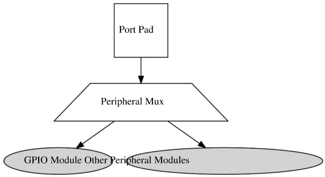
flowchart
graph TD
A["Port Pad"] --> B["Peripheral Mux"]
B --> C["GPIO Module Other Peripheral Modules"]
19.3 Special Considerations
The SAM D20/D21 port pin input sampling mode is set in groups of four physical pins; setting the sampling mode of any pin in a sub-group of eight I/O pins will configure the sampling mode of the entire sub-group.
High Drive Strength output driver mode is not available on all device pins - refer to your device specific datasheet.
19.4 Extra Information
For extra information see Extra Information for SYSTEM PINMUX Driver. This includes:
• Acronyms
- Dependencies
- Errata
- Module History
19.5 Examples
For a list of examples related to this driver, see Examples for SYSTEM PINMUX Driver.
19.6 API Overview
19.6.1 Structure Definitions
19.6.1.1 Struct system\_pinmux\_config
Configuration structure for a port pin instance. This structure should be structure should be initialized by the system_pinmux_get_config_defaults() function before being modified by the user application.
Table 19-1. Members
| Type Name Description | ||
| enum system_pinmux_pin_dir direction Port buffer input/output direction. | ||
| enum system_pinmux_pin_pull input_pull Logic level pull of the input buffer. | ||
| uint8_t mux_position MUX index of the peripheral | that should control the pin, if peripheral control is desired. For GPIO use, this should be set to SYSTEM_PINMUX_GPIO. | |
| bool powersave Enable lowest possible powerstate | on the pin ^1 | |
Notes: ^1 All other configurations will be ignored, the pin will be disabled
19.6.2 Macro Definitions
19.6.2.1 Macro SYSTEM\_PINMUX\_GPIO
#define SYSTEM_PINMUX_GPIO (1 << 7)
Peripheral multiplexer index to select GPIO mode for a pin.
19.6.3 Function Definitions
19.6.3.1 Configuration and initialization
Function system\_pinmux\_get\_config\_defaults()
Initializes a Port pin configuration structure to defaults.
void system_pinmux_get_config_defaults(
struct system_pinmux_config *const config)
Initializes a given Port pin configuration structure to a set of known default values. This function should be called on all new instances of these configuration structures before being modified by the user application.
The default configuration is as follows:
• Non peripheral (i.e. GPIO) controlled
- Input mode with internal pull-up enabled
Table 19-2. Parameters
| Data direction Parameter name | Description | |
| [out] | config | Configuration structure to initialize to default values |
Function system\_pinmux\_pin\_set\_config()
Writes a Port pin configuration to the hardware module.
void system_pinmux_pin_set_config(
const uint8_t gpio_pin,
const struct system_pinmux_config *const config)
Writes out a given configuration of a Port pin configuration to the hardware module.
Note
If the pin direction is set as an output, the pull-up/pull-down input configuration setting is ignored.
Table 19-3. Parameters
| Data direction Parameter name Description | |
| [in] gpio_pin Index of the GPIO pin to configure. | |
| [in] config Configuration settings for the pin. |
Function system\_pinmux\_group\_set\_config()
Writes a Port pin group configuration to the hardware module.
void system_pinmux_group_set_config(
PortGroup *const port,
const uint32_t mask,
const struct system_pinmux_config *const config)
Writes out a given configuration of a Port pin group configuration to the hardware module.
Note
If the pin direction is set as an output, the pull-up/pull-down input configuration setting is ignored.
Table 19-4. Parameters
| Data direction Parameter name Description | |
| [in] port Base of the PORT module to | configure. |
| [in] mask Mask of the port pin(s) to | configure. |
| [in] config Configuration settings for the pin. |
19.6.3.2 Special mode configuration (physical group orientated)
Function system\_pinmux\_get\_group\_from\_gpio\_pin()
Retrieves the PORT module group instance from a given GPIO pin number.
PortGroup * system_pinmux_get_group_from_gpio_pin(const uint8_t gpio_pin)
Retrieves the PORT module group instance associated with a given logical GPIO pin number.
Table 19-5. Parameters
| Data direction Parameter name Description | |
| [in] gpio_pin Index of the GPIO pin to convert. |
Returns
Base address of the associated PORT module.
Function system\_pinmux\_group\_set\_input\_sample\_mode()
Configures the input sampling mode for a group of pins.
void system_pinmux_group_set_input_sample_mode(
PortGroup *const port,
const uint32_t mask,
const enum system_pinmux_pin_sample mode)
Configures the input sampling mode for a group of pins, to control when the physical I/O pin value is sampled and stored inside the microcontroller.
Table 19-6. Parameters
| Data direction Parameter name Description | |
| [in] port Base of the PORT module to | |
| [in] mask Mask of the port pin(s) to | |
| [in] mode New pin sampling mode to |
19.6.3.3 Special mode configuration (logical pin orientated)
Function system\_pinmux\_pin\_get\_mux\_position()
Retrieves the currently selected MUX position of a logical pin.
uint8_t system_pinmux_pin_get_mux_position(const uint8_t gpio_pin)
Retrieves the selected MUX peripheral on a given logical GPIO pin.
Table 19-7. Parameters
| Data direction Parameter name Description | |
| [in] gpio_pin Index of the GPIO pin to configure. |
Returns
Currently selected peripheral index on the specified pin.
Function system\_pinmux\_pin\_set\_input\_sample\_mode()
Configures the input sampling mode for a GPIO pin.
void system_pinmux_pin_set_input_sample_mode(
const uint8_t gpio_pin,
const enum system_pinmux_pin_sample_mode)
Configures the input sampling mode for a GPIO input, to control when the physical I/O pin value is sampled and stored inside the microcontroller.
Table 19-8. Parameters
| Data direction Parameter name Description | |
| [in] gpio_pin Index of the GPIO pin to configure. | |
| [in] mode New pin sampling mode to | configure. |
19.6.4 Enumeration Definitions
19.6.4.1 Enum system\_pinmux\_pin\_dir
Enum for the possible pin direction settings of the port pin configuration structure, to indicate the direction the pin should use.
Table 19-9. Members
| Enum value Description | |
| SYSTEM_PINMUX_PIN_DIR_INPUT The pin's input buffer should be enabled, so that the pin state can be read. | |
| SYSTEM_PINMUX_PIN_DIR_OUTPUT The pin's output buffer should be enabled, so that the pin state can be set (but not read back). | |
| SYSTEM_PINMUX_PIN_DIR_OUTPUT_WITH_READBACK The pin's output and input buffers should both be enabled, so that the pin state can be set and read back. | |
19.6.4.2 Enum system\_pinmux\_pin\_pull
Enum for the possible pin pull settings of the port pin configuration structure, to indicate the type of logic level pull the pin should use.
Table 19-10. Members
| Enum value Description | |
| SYSTEM_PINMUX_PIN_PULL_NONE No logical pull should be applied to the pin. | |
| SYSTEM_PINMUX_PIN_PULL_UP Pin should be pulled up when idle. | |
| SYSTEM_PINMUX_PIN_PULL_DOWN Pin should be pulled down when idle. | |
19.6.4.3 Enum system\_pinmux\_pin\_sample
Enum for the possible input sampling modes for the port pin configuration structure, to indicate the type of sampling a port pin should use.
Table 19-11. Members
| Enum value Description | |
| SYSTEM_PINMUX_PIN_SAMPLE_CONTINUOUS Pin input buffer should continuously sample the pin state. | |
| SYSTEM_PINMUX_PIN_SAMPLE_ONDEMAND Pin input buffer should be enabled when the IN register is read. | |
19.7 Extra Information for SYSTEM PINMUX Driver
19.7.1 Acronyms
The table below presents the acronyms used in this module:
| Acronym Description | |
| GPIO General Purpose Input/Output | |
| MUX Multiplexer |
19.7.2 Dependencies
This driver has the following dependencies:
• None
19.7.3 Errata
There are no errata related to this driver.
19.7.4 Module History
An overview of the module history is presented in the table below, with details on the enhancements and fixes made to the module since its first release. The current version of this corresponds to the newest version in the table.
| Changelog |
| Removed code of open drain, slew limit and drive strength features. |
| Fixed broken sampling mode function implementations, which wrote corrupt configuration values to the device registers. |
| Added missing NULL pointer asserts to the PORT driver functions. |
| Initial Release |
19.8 Examples for SYSTEM PINMUX Driver
This is a list of the available Quick Start guides (QSGs) and example applications for SAM D20/D21 System Pin Multiplexer Driver (SYSTEM PINMUX). QSGs are simple examples with step-by-step instructions to configure and use this driver in a selection of use cases. Note that QSGs can be compiled as a standalone application or be added to the user application.
- Quick Start Guide for SYSTEM PINMUX - Basic
19.8.1 Quick Start Guide for SYSTEM PINMUX - Basic
In this use case, the PINMUX module is configured for:
• One pin in input mode, with pull-up enabled, connected to the GPIO module
- Sampling mode of the pin changed to sample on demand
This use case sets up the PINMUX to configure a physical I/O pin set as an input with pull-up. and changes the sampling mode of the pin to reduce power by only sampling the physical pin state when the user application attempts to read it.
19.8.1.1 Setup
Prerequisites
There are no special setup requirements for this use-case.
Code
Copy-paste the following setup code to your application:
struct system_pinmux_config config_pinmux;
system_pinmux_get_config_defaults(&config_pinmux);
config_pinmux.mux_position = SYSTEM_PINMUX_GPIO;
config_pinmux.direction = SYSTEM_PINMUX_PIN_DIR_INPUT;
config_pinmux.input_pull = SYSTEM_PINMUX_PIN_PULL_UP;
system_pinmux_pin_set_config(10, &config_pinmux);
Workflow
- Create a PINMUX module pin configuration struct, which can be filled out to adjust the configuration of a single port pin.
struct system_pinmux_config config_pinmux;
- Initialize the pin configuration struct with the module's default values.
system_pinmux_get_config_defaults(&config_pinmux);
Note
This should always be performed before using the configuration struct to ensure that all values are initialized to known default settings.
- Adjust the configuration struct to request an input pin with pullup connected to the GPIO peripheral.
config_pinmux.mux_position = SYSTEM_PINMUX_GPIO;
config_pinmux.direction = SYSTEM_PINMUX_PIN_DIR_INPUT;
config_pinmux.input_pull = SYSTEM_PINMUX_PIN_PULL_UP;
- Configure GPIO10 with the initialized pin configuration struct, to enable the input sampler on the pin.
system_pinmux_pin_set_config(10, &config_pinmux);
19.8.1.2 Use Case
Code
Copy-paste the following code to your user application:
system_pinmux_pin_set_input_sample_mode(10, SYSTEM_PINMUX_PIN_SAMPLE_ONDEMAND);
while (true) {
/* Infinite loop */
}
Workflow
- Adjust the configuration of the pin to enable on-demand sampling mode.
system_pinmux_pin_set_input_sample_mode(10, SYSTEM_PINMUX_PIN_SAMPLE_ONDEMAND);
20. SAM D20/D21 Timer/Counter Driver (TC)
This driver for SAM D20/D21 devices provides an interface for the configuration and management of the timer modules within the device, for waveform generation and timing operations. The following driver API modes are covered by this manual:
- Polled APIs
- Callback APIs
The following peripherals are used by this module:
• TC (Timer/Counter)
The outline of this documentation is as follows:
- Prerequisites
- Module Overview
• Special Considerations - Extra Information
- Examples
- API Overview
20.1 Prerequisites
There are no prerequisites for this module.
20.2 Module Overview
The Timer/Counter (TC) module provides a set of timing and counting related functionality, such as the generation of periodic waveforms, the capturing of a periodic waveform's frequency/duty cycle, and software timekeeping for periodic operations. TC modules can be configured to use an 8-, 16-, or 32-bit counter size.
This TC module for the SAM D20/D21 is capable of the following functions:
• Generation of PWM signals
- Generation of timestamps for events
- General time counting
• Waveform period capture
• Waveform frequency capture
Figure 20-1: Basic overview of the TC module on page 460 shows the overview of the TC module design.
Figure 20-1. Basic overview of the TC module
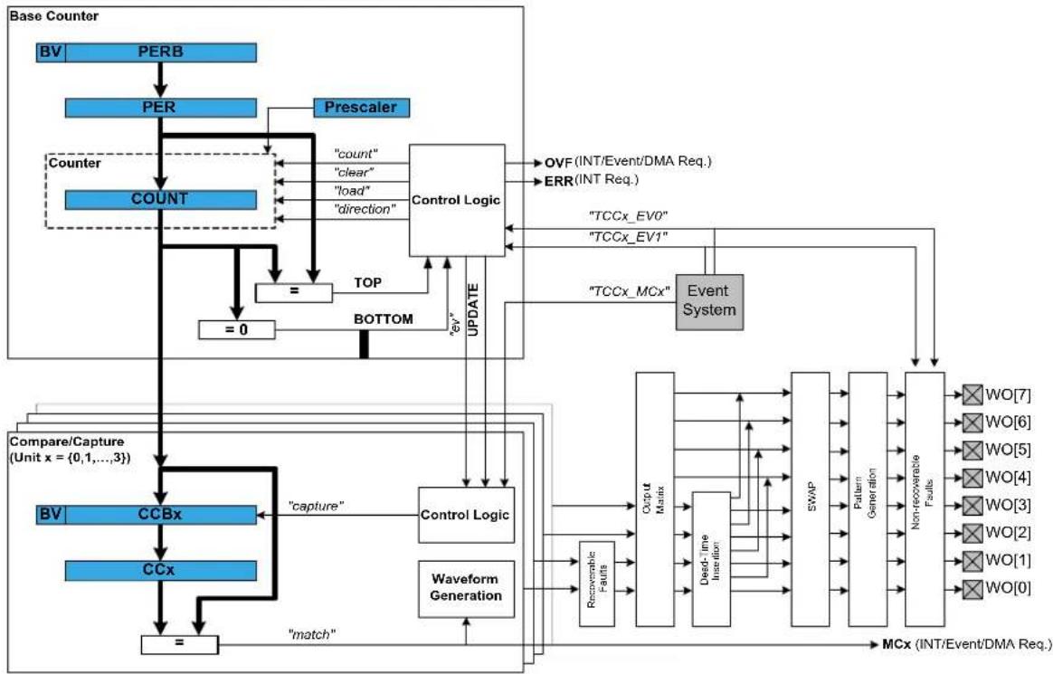
flowchart
graph TD
A["Base Counter"] --> B["BV"]
B --> C["PERB"]
C --> D["PER"]
D --> E["Counter"]
E --> F["COUNT"]
F --> G["="]
G --> H["=0"]
H --> I["STOP"]
I --> J["TOP"]
J --> K["BOTTOM"]
K --> L["Control Logic"]
L --> M["count"]
L --> N["clear"]
L --> O["load"]
L --> P["direction"]
M --> Q["OVF (INT/Event/DMA Req.)"]
N --> R["ERR (INT Req.)"]
O --> S["TCCx_EV0"]
P --> T["TCCx_EV1"]
U["Compare/Capture (Unit x = {0,1,...,3})"] --> V["BV"]
V --> W["CCBx"]
W --> X["capture"]
X --> Y["Control Logic"]
Y --> Z["Waveform Generation"]
Z --> AA["Recoverable Faults"]
AA --> AB["Output Matrix"]
AB --> AC["Dead-Time Inactivation"]
AC --> AD["SWAP"]
AD --> AE["Pattern Generation"]
AE --> AF["Non-recoverable Faults"]
AF --> AG["WO[7"]]
AF --> AH["WO[6"]]
AF --> AI["WO[5"]]
AF --> AJ["WO[4"]]
AF --> AK["WO[3"]]
AF --> AL["WO[2"]]
AF --> AM["WO[1"]]
AF --> AN["WO[0"]]
AG --> AO["MCx (INT/Event/DMA Req.)"]
AH --> AO
AI --> AO
AJ --> AO
AK --> AO
AL --> AO
AM --> AO
AN --> AO
AO --> AP["match"]
20.2.1 Functional Description
Independent of the configured counter size, each TC module can be set up in one of two different modes; capture and compare.
In capture mode, the counter value is stored when a configurable event occurs. This mode can be used to generate timestamps used in event capture, or it can be used for the measurement of a periodic input signal's frequency/duty cycle.
In compare mode, the counter value is compared against one or more of the configured channel compare values. When the counter value coincides with a compare value an action can be taken automatically by the module, such as generating an output event or toggling a pin when used for frequency or PWM signal generation.
Note
The connection of events between modules requires the use of the SAM D20/D21 Event System Driver (EVENTS) to route output event of one module to the input event of another. For more information on event routing, refer to the event driver documentation.
20.2.2 Timer/Counter Size
Each timer module can be configured in one of three different counter sizes; 8-, 16-, and 32-bits. The size of the counter determines the maximum value it can count to before an overflow occurs and the count is reset back to zero. Table 20-1: Timer counter sizes and their maximum count values on page 460 shows the maximum values for each of the possible counter sizes.
Table 20-1. Timer counter sizes and their maximum count values
| Counter Size Max (Hexadecimal) Max (Decimal) | |
| 8-bit 0xFF 255 | |
| 16-bit 0xFFFF 65,535 | |
| 32-bit 0xFFFFFFFF 4,294,967,295 |
When using the counter in 16- or 32-bit count mode, Compare Capture register 0 (CC0) is used to store the period value when running in PWM generation match mode.
When using 32-bit counter size, two 16-bit counters are chained together in a cascade formation. Even numbered TC modules (e.g. TC0, TC2) can be configured as 32-bit counters. The odd numbered counters will act as slaves to the even numbered masters, and will not be reconfigurable until the master timer is disabled. The pairing of timer modules for 32-bit mode is shown in Table 20-2: TC master and slave module pairings on page 461.
Table 20-2. TC master and slave module pairings
| Master TC Module Slave TC Module | |
| TC0 TC1 | |
| TC2 TC3 | |
| ... ... | |
| TCn-1 TCn |
20.2.3 Clock Settings
20.2.3.1 Clock Selection
Each TC peripheral is clocked asynchronously to the system clock by a GCLK (Generic Clock) channel. The GCLK channel connects to any of the GCLK generators. The GCLK generators are configured to use one of the available clock sources on the system such as internal oscillator, external crystals etc. - see the Generic Clock driver for more information.
20.2.3.2 Prescaler
Each TC module in the SAM D20/D21 has its own individual clock prescaler, which can be used to divide the input clock frequency used in the counter. This prescaler only scales the clock used to provide clock pulses for the counter to count, and does not affect the digital register interface portion of the module, thus the timer registers will synchronized to the raw GCLK frequency input to the module.
As a result of this, when selecting a GCLK frequency and timer prescaler value the user application should consider both the timer resolution required and the synchronization frequency, to avoid lengthy synchronization times of the module if a very slow GCLK frequency is fed into the TC module. It is preferable to use a higher module GCLK frequency as the input to the timer and prescale this down as much as possible to obtain a suitable counter frequency in latency-sensitive applications.
20.2.3.3 Reloading
Timer modules also contain a configurable reload action, used when a re-trigger event occurs. Examples of a re-trigger event are the counter reaching the max value when counting up, or when an event from the event system tells the counter to re-trigger. The reload action determines if the prescaler should be reset, and when this should happen. The counter will always be reloaded with the value it is set to start counting from. The user can choose between three different reload actions, described in Table 20-3: TC module reload actions on page 461.
Table 20-3. TC module reload actions
| Reload Action Description | |
| TC_RELOAD_ACTION_GCLK on page 478 Reload TC counter value on next GCLK cycle. Leave prescaler as-is. | |
| TC_RELOAD_ACTION_PRESC on page 478 Reloads TC counter value on next prescaler clock.Leave prescaler as-is. | |
| TC_RELOAD_ACTION_RESYNC on page 478 Reload TC counter value on next GCLK cycle. Clear prescaler to zero. | |
The reload action to use will depend on the specific application being implemented. One example is when an external trigger for a reload occurs; if the TC uses the prescaler, the counter in the prescaler should not have a value between zero and the division factor. The TC counter and the counter in the prescaler should both start at zero. When the counter is set to re-trigger when it reaches the max value on the other hand, this is not the right
option to use. In such a case it would be better if the prescaler is left unaltered when the re-trigger happens, letting the counter reset on the next GCLK cycle.
20.2.4 Compare Match Operations
In compare match operation, Compare/Capture registers are used in comparison with the counter value. When the timer's count value matches the value of a compare channel, a user defined action can be taken.
20.2.4.1 Basic Timer
A Basic Timer is a simple application where compare match operations is used to determine when a specific period has elapsed. In Basic Timer operations, one or more values in the module's Compare/Capture registers are used to specify the time (as a number of prescaled GCLK cycles) when an action should be taken by the microcontroller. This can be an Interrupt Service Routine (ISR), event generator via the event system, or a software flag that is polled via the user application.
20.2.4.2 Waveform Generation
Waveform generation enables the TC module to generate square waves, or if combined with an external passive low-pass filter, analog waveforms.
20.2.4.3 Waveform Generation - PWM
Pulse width modulation is a form of waveform generation and a signalling technique that can be useful in many situations. When PWM mode is used, a digital pulse train with a configurable frequency and duty cycle can be generated by the TC module and output to a GPIO pin of the device.
Often PWM is used to communicate a control or information parameter to an external circuit or component. Differing impedances of the source generator and sink receiver circuits is less of an issue when using PWM compared to using an analog voltage value, as noise will not generally affect the signal's integrity to a meaningful extent.
Figure 20-2: Example of PWM in normal mode, and different counter operations on page 462 illustrates operations and different states of the counter and its output when running the counter in PWM normal mode. As can be seen, the TOP value is unchanged and is set to MAX. The compare match value is changed at several points to illustrate the resulting waveform output changes. The PWM output is set to normal (i.e. non-inverted) output mode.
Figure 20-2. Example of PWM in normal mode, and different counter operations
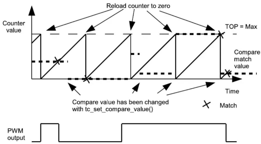
flowchart
graph TD
A["Counter value"] --> B{Reload counter to zero}
B --> C["TOP = Max"]
C --> D["Compare match value"]
D --> E["Compare value has been changed with tc_set_compare_value()"]
E --> F["Match"]
F --> G["PWM output"]
In Figure 20-3: Example of PWM in match mode, and different counter operations on page 463, the counter is set to generate PWM in Match mode. The PWM output is inverted via the appropriate configuration option in the TC driver configuration structure. In this example, the counter value is changed once, but the compare match value is kept unchanged. As can be seen, it is possible to change the TOP value when running in PWM match mode.
Figure 20-3. Example of PWM in match mode, and different counter operations
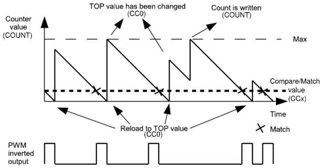
line
| Event | Value | |-------|-------| | TOP value has been changed (CC0) | High | | Count is written (COUNT) | High | | Compare/Match value (CCx) | Dashed line | | Match | X-marked point | | Reload to TOP value (CC0) | Low | | PWM inverted output | Waveform pattern |20.2.4.4 Waveform Generation - Frequency
Frequency Generation mode is in many ways identical to PWM generation. However, in Frequency Generation a toggle only occurs on the output when a match on a capture channels occurs. When the match is made, the timer value is reset, resulting in a variable frequency square wave with a fixed 50% duty cycle.
20.2.4.5 Capture Operations
In capture operations, any event from the event system or a pin change can trigger a capture of the counter value. This captured counter value can be used as a timestamp for the event, or it can be used in frequency and pulse width capture.
20.2.4.6 Capture Operations - Event
Event capture is a simple use of the capture functionality, designed to create timestamps for specific events. When the TC module's input capture pin is externally toggled, the current timer count value is copied into a buffered register which can then be read out by the user application.
Note that when performing any capture operation, there is a risk that the counter reaches its top value (MAX) when counting up, or the bottom value (zero) when counting down, before the capture event occurs. This can distort the result, making event timestamps to appear shorter than reality; the user application should check for timer overflow when reading a capture result in order to detect this situation and perform an appropriate adjustment.
Before checking for a new capture, TC_STATUS_COUNT_OVERFLOW should be checked. The response to an overflow error is left to the user application, however it may be necessary to clear both the capture overflow flag and the capture flag upon each capture reading.
20.2.4.7 Capture Operations - Pulse Width
Pulse Width Capture mode makes it possible to measure the pulse width and period of PWM signals. This mode uses two capture channels of the counter. This means that the counter module used for Pulse Width Capture can not be used for any other purpose. There are two modes for pulse width capture; Pulse Width Period (PWP)
and Period Pulse Width (PPW). In PWP mode, capture channel 0 is used for storing the pulse width and capture channel 1 stores the observed period. While in PPW mode, the roles of the two capture channels is reversed.
As in the above example it is necessary to poll on interrupt flags to see if a new capture has happened and check that a capture overflow error has not occurred.
20.2.5 One-shot Mode
TC modules can be configured into a one-shot mode. When configured in this manner, starting the timer will cause it to count until the next overflow or underflow condition before automatically halting, waiting to be manually triggered by the user application software or an event signal from the event system.
20.2.5.1 Wave Generation Output Inversion
The output of the wave generation can be inverted by hardware if desired, resulting in the logically inverted value being output to the configured device GPIO pin.
20.3 Special Considerations
The number of capture compare registers in each TC module is dependent on the specific SAM D20/D21 device being used, and in some cases the counter size.
The maximum amount of capture compare registers available in any SAM D20/D21 device is two when running in 32-bit mode and four in 8-, and 16-bit modes.
20.4 Extra Information
For extra information see Extra Information for TC Driver. This includes:
- Acronyms
- Dependencies
- Errata
- Module History
20.5 Examples
For a list of examples related to this driver, see Examples for TC Driver.
20.6 API Overview
20.6.1 Variable and Type Definitions
20.6.1.1 Type tc_callback_t
typedef void(* tc_callback_t )(struct tc_module *const module)
20.6.2 Structure Definitions
20.6.2.1 Struct tc_16bit_config
Table 20-4. Members
| Type Name Description | ||
| uint16_t compare_capture_channel[] | Value to be used for compare | match on each channel. |
| uint16_t value Initial timer count value. | ||
20.6.2.2 Struct tc\_32bit\_config
Table 20-5. Members
| Type Name Description | ||
| uint32_t compare_capture_channel[] | Value to be used for compare | match on each channel. |
| uint32_t value Initial timer count value. | ||
20.6.2.3 Struct tc\_8bit\_config
Table 20-6. Members
| Type Name Description | ||
| uint8_t compare_capture_channel[] Value to be used for compare | match on each channel. | |
| uint8_t period Where to count to or from | depending on the direction on the counter. | |
| uint8_t value Initial timer count value. | ||
20.6.2.4 Struct tc\_config
Configuration struct for a TC instance. This structure should be initialized by the tc_get_config_defaults function before being modified by the user application.
Table 20-7. Members
| Type Name Description | ||
| union tc_config.@410 @410 Access the different counter size | settings though this configuration member. | |
| enum tc_clock_prescaler clock_prescaler Specifies the prescaler value for | GCLK_TC. | |
| enum gclk_generator clock_source GCLK generator used to clock the | peripheral. | |
| enum tc_count_direction | count_direction | Specifies the direction for the TC to count. |
| enum tc_counter_size | counter_size | Specifies either 8-, 16-, or 32-bit counter size. |
| bool | enable_capture_on_channel[] | Specifies which channel(s) to enable channel capture operation on. |
| bool | oneshot When true, one-shot will stop the TC on next hardware or software re-trigger event or overflow/underflow. | |
| struct tc_pwm_channel | pwm_channel[] | Specifies the PWM channel for TC. |
| enum tc_reload_action | reload_action | Specifies the reload or reset time of the counter and prescaler resynchronization on a re-trigger event for the TC. |
| bool run_in_standby When true the module is enabled | during standby. | |
| enum tc_wave_generation wave_generation Specifies which waveform | generation mode to use. | |
| uint8_t waveform_invert_output Specifies which channel(s) to invert | the waveform on. | |
20.6.2.5 Union tc\_config.\_\_unnamed\_\_
Access the different counter size settings though this configuration member.
Table 20-8. Members
| Type Name Description | ||
| struct tc_16bit_config counter_16_bit | Struct for 16-bit specific timer | configuration. |
| struct tc_32bit_config counter_32_bit | Struct for 32-bit specific timer | configuration. |
| struct tc_8bit_config counter_8_bit | Struct for 8-bit specific timer | configuration. |
20.6.2.6 Struct tc\_events
Event flags for the tc_enable_events() and tc_disable_events().
Table 20-9. Members
| Type Name Description | ||
| enum tc_event_action event_action Specifies which event to trigger if | an event is triggered. | |
| bool | generate_event_on_compare_chann | Generate an output event on a compare channel match. |
| bool generate_event_on_overflow | Generate an output event on | counter overflow. |
| bool invert_event_input | Specifies if the input event source | is inverted, when used in PWP or PPW event action modes. |
| bool on_event_perform_action | Perform the configured event | action when an incoming event is signalled. |
20.6.2.7 Struct tc\_module
TC software instance structure, used to retain software state information of an associated hardware module instance.
Note
The fields of this structure should not be altered by the user application; they are reserved for module-internal use only.
20.6.2.8 Struct tc\_pwm\_channel
Table 20-10. Members
| Type Name Description | ||
| bool enabled When true, PWM output for the | given channel is enabled. | |
| uint32_t pin_mux Specifies MUX setting for each | output channel pin. | |
| uint32_t pin_out Specifies pin output for each | channel. | |
20.6.3 Macro Definitions
20.6.3.1 Module status flags
TC status flags, returned by tc_get_status() and cleared by tc_clear_status().
Macro TC_STATUS_CHANNEL_0_MATCH
#define TC_STATUS_CHANNEL_0_MATCH (1UL << 0)
Timer channel 0 has matched against its compare value, or has captured a new value.
Macro TC_STATUS_CHANNEL_1_MATCH
#define TC_STATUS_CHANNEL_1_MATCH (1UL << 1)
Timer channel 1 has matched against its compare value, or has captured a new value.
Macro TC_STATUS_SYNC_READY
#define TC_STATUS_SYNC_READY (1UL << 2)
Timer register synchronization has completed, and the synchronized count value may be read.
Macro TC_STATUS_CAPTURE_OVERFLOW
#define TC_STATUS_CAPTURE_OVERFLOW (1UL << 3)
A new value was captured before the previous value was read, resulting in lost data.
Macro TC_STATUS_COUNT_OVERFLOW
#define TC_STATUS_COUNT_OVERFLOW (1UL << 4)
The timer count value has overflowed from its maximum value to its minimum when counting upward, or from its minimum value to its maximum when counting downward.
20.6.4 Function Definitions
20.6.4.1 Driver Initialization and Configuration
Function tc\_is\_syncing()
Determines if the hardware module(s) are currently synchronizing to the bus.
bool tc_is_syncing(
const struct tc_module *const module_inst)
Checks to see if the underlying hardware peripheral module(s) are currently synchronizing across multiple clock domains to the hardware bus. This function can be used to delay further operations on a module until such time that it is ready, to prevent blocking delays for synchronization in the user application.
Table 20-11. Parameters
| Data direction Parameter name Description | |
| [in] module_inst Pointer to the software module | instance struct |
Returns
Synchronization status of the underlying hardware module(s).
Table 20-12. Return Values
| Return value Description | |
| true if the module has completed synchronization | |
| false if the module synchronization is ongoing |
Function tc\_get\_config\_defaults()
Initializes config with predefined default values.
void tc_get_config_defaults(
struct tc_config *const config)
This function will initialize a given TC configuration structure to a set of known default values. This function should be called on any new instance of the configuration structures before being modified by the user application.
The default configuration is as follows:
• GCLK generator 0 (GCLK main) clock source
• 16-bit counter size on the counter
- No prescaler
• Normal frequency wave generation
• GCLK reload action
- Don't run in standby
• No inversion of waveform output
- No capture enabled
• No event input enabled
Count upward
- Don't perform one-shot operations
- No event action
• No channel 0 PWM output
• No channel 1 PWM output
- Counter starts on 0
• Capture compare channel 0 set to 0
• Capture compare channel 1 set to 0
• No PWM pin output enabled
• Pin and Mux configuration not set
Table 20-13. Parameters
| Data direction Parameter name Description | |
| [out] config Pointer to a TC module |
Function tc\_init()
Initializes a hardware TC module instance.
enum status_code tc_init(
struct tc_module *const module_inst,
Tc *const hw,
const struct tc_config *const config)
Enables the clock and initializes the TC module, based on the given configuration values.
Table 20-14. Parameters
| Data direction Parameter name Description | |
| [in, out] module_inst Pointer to the software module | instance struct |
| [in] hw Pointer to the TC hardware module | |
| [in] config Pointer to the TC configuration | options struct |
Returns
Status of the initialization procedure.
Table 20-15. Return Values
| Return value Description | |
| STATUS_OK The module was initialized successfully | |
| STATUS_BUSY Hardware module was busy when the initialization procedure was attempted | |
| STATUS_INVALID_ARG An invalid configuration option | or argument was supplied |
| STATUS_ERR_DENIED Hardware module was already enabled, or the hardware module is configured in 32 bit slave mode | |
20.6.4.2 Event Management
Function tc\_enable\_events()
Enables a TC module event input or output.
void tc_enable_events(
struct tc_module *const module_inst,
struct tc_events *const events)
Enables one or more input or output events to or from the TC module. See tc_events for a list of events this module supports.
Note
Events cannot be altered while the module is enabled.
Table 20-16. Parameters
| Data direction Parameter name Description | |
| [in] module_inst Pointer to the software module | instance struct |
| [in] events Struct containing flags of events to | enable |
Function tc\_disable\_events()
Disables a TC module event input or output.
void tc_disable_events(
struct tc_module *const module_inst,
struct tc_events *const events)
Disables one or more input or output events to or from the TC module. See tc_events for a list of events this module supports.
Note
Events cannot be altered while the module is enabled.
Table 20-17. Parameters
| Data direction Parameter name Description | |
| [in] module_inst Pointer to the software module | instance struct |
| [in] events Struct containing flags of events to | disable |
Resets the TC module, restoring all hardware module registers to their default values and disabling the module. The TC module will not be accessible while the reset is being performed.
Note
When resetting a 32-bit counter only the master TC module's instance structure should be passed to the function.
Table 20-18. Parameters
| Data direction Parameter name Description | |
| [in] module_inst Pointer to the software module | instance struct |
Returns
Status of the procedure
Table 20-19. Return Values
| Return value Description | |
| STATUS_OK The module was reset successfully | |
| STATUS_ERR_UNSUPPORTED_DEV A 32-bit slave TC module was passed to the function.Only use reset on master TC. | |
Function tc\_enable()
Enable the TC module.
void tc_enable(
const struct tc_module *const module_inst)
Enables a TC module that has been previously initialized. The counter will start when the counter is enabled.
Note
When the counter is configured to re-trigger on an event, the counter will not start until the start function is used.
Table 20-20. Parameters
| Data direction Parameter name Description | |
| [in] module_inst Pointer to the software module | instance struct |
Function tc\_disable()
Disables the TC module.
void tc_disable(
const struct tc_module *const module_inst)
Disables a TC module and stops the counter.
Table 20-21. Parameters
| Data direction Parameter name Description | |
| [in] module_inst Pointer to the software module | instance struct |
20.6.4.4 Get/Set Count Value
Function tc\_get\_count\_value()
Get TC module count value.
uint32_t tc_get_count_value(
const struct tc_module *const module_inst)
Retrieves the current count value of a TC module. The specified TC module may be started or stopped.
Table 20-22. Parameters
| Data direction Parameter name Description | |
| [in] module_inst Pointer to the software module | instance struct |
Returns
Count value of the specified TC module.
Function tc\_set\_count\_value()
Sets TC module count value.
enum status_code tc_set_count_value(
const struct tc_module *const module_inst,
const uint32_t count)
Sets the current timer count value of a initialized TC module. The specified TC module may be started or stopped.
Table 20-23. Parameters
| Data direction Parameter name Description | |
| [in] module_inst Pointer to the software module | instance struct |
Data direction Parameter name Description
[in] count New timer count value to set
Returns
Status of the count update procedure.
Table 20-24. Return Values
| Return value Description | |
| STATUS_OK The timer count was updated successfully | |
| STATUS_ERR_INVALID_ARG An invalid timer counter size was specified | |
20.6.4.5 Start/Stop Counter
Function tc\_stop\_counter()
Stops the counter.
void tc_stop_counter(
const struct tc_module *const module_inst)
This function will stop the counter. When the counter is stopped the value in the count value is set to 0 if the counter was counting up, or max or the top value if the counter was counting down when stopped.
Table 20-25. Parameters
| Data direction Parameter name Description | |
| [in] module_inst Pointer to the software module | instance struct |
Function tc\_start\_counter()
Starts the counter.
void tc_start_counter( const struct tc_module *const module_inst)
Starts or restarts an initialized TC module's counter.
Table 20-26. Parameters
| Data direction Parameter name Description | |
| [in] module_inst Pointer to the software module | instance struct |
20.6.4.6 Get Capture Set Compare
Function tc\_get\_capture\_value()
Gets the TC module capture value.
uint32_t tc_get_capture_value(
const struct tc_module *const module_inst,
const enum tc_compare_capture_channel channel_index)
Retrieves the capture value in the indicated TC module capture channel.
Table 20-27. Parameters
| Data direction Parameter name Description | |
| [in] module_inst Pointer to the software module | instance struct |
| [in] channel_index Index of the Compare Capture | channel to read |
Returns
Capture value stored in the specified timer channel.
Function tc\_set\_compare\_value()
Sets a TC module compare value.
enum status_code tc_set_compare_value(
const struct tc_module *const module_inst,
const enum tc_compare_capture_channel channel_index,
const uint32_t compare_value)
Writes a compare value to the given TC module compare/capture channel.
Table 20-28. Parameters
| Data direction Parameter name Description | |
| [in] module_inst Pointer to the software module | instance struct |
| [in] channel_index Index of the compare channel to | write to |
| [in] compare New compare value to set |
Returns
Status of the compare update procedure.
Table 20-29. Return Values
| Return value Description | |
| STATUS_OK The compare value was updated successfully | |
| STATUS_ERR_INVALID_ARG An invalid channel index was supplied | |
20.6.4.7 Set Top Value
Function tc\_set\_top\_value()
Set the timer TOP/period value.
enum status_code tc_set_top_value(
const struct tc_module *const module_inst, const uint32_t top_value)
For 8-bit counter size this function writes the top value to the period register.
For 16- and 32-bit counter size this function writes the top value to Capture Compare register 0. The value in this register can not be used for any other purpose.
Note
This function is designed to be used in PWM or frequency match modes only. When the counter is set to 16- or 32-bit counter size. In 8-bit counter size it will always be possible to change the top value even in normal mode.
Table 20-30. Parameters
| Data direction Parameter name Description | |
| [in] module_inst Pointer to the software module | instance struct |
| [in] top_value New timer TOP value to set |
Returns
Status of the TOP set procedure.
Table 20-31. Return Values
| Return value Description | |
| STATUS_OK The timer TOP value was updated successfully | |
| STATUS_ERR_INVALID_ARG The configured TC module counter size in the module instance is invalid. | |
20.6.4.8 Status Management
Function tc\_get\_status()
Retrieves the current module status.
uint32_t tc_get_status(
struct tc_module *const module_inst)
Retrieves the status of the module, giving overall state information.
Table 20-32. Parameters
| Data direction Parameter name Description | |
| [in] module_inst Pointer to the TC software instance | struct |
Returns
Bitmask of TC_STATUS_* flags
Table 20-33. Return Values
| Return value Description | |
| TC_STATUS_CHANNEL_0_MATCH Timer channel 0 compare/capture match | |
| Return value Description | |
| TC_STATUS_CHANNEL_1_MATCH Timer channel 1 compare/capture match | |
| TC_STATUS_SYNC_READY Timer read synchronization has completed | |
| TC_STATUS_CAPTURE_OVERFLOW Timer capture data has overflowed | |
| TC_STATUS_COUNT_OVERFLOW Timer count value has overflowed | |
Function tc\_clear\_status()
Clears a module status flag.
void tc_clear_status(
struct tc_module *const module_inst,
const uint32_t status_flags)
Clears the given status flag of the module.
Table 20-34. Parameters
| Data direction Parameter name Description | |
| [in] module_inst Pointer to the TC software instance | struct |
| [in] status_flags | Bitmask of TC_STATUS_* flags to clear |
20.6.5 Enumeration Definitions
20.6.5.1 Enum tc_callback
Enum for the possible callback types for the TC module.
Table 20-35. Members
| Enum value Description | |
| TC_CALLBACK_OVERFLOW Callback for TC overflow | |
| TC_CALLBACK_ERROR Callback for capture overflow error | |
| TC_CALLBACK_CC_CHANNEL0 | Callback for capture compare channel 0 |
| TC_CALLBACK_CC_CHANNEL1 | Callback for capture compare channel 1 |
20.6.5.2 Enum tc\_clock\_prescaler
This enum is used to choose the clock prescaler configuration. The prescaler divides the clock frequency of the TC module to make the counter count slower.
Table 20-36. Members
| Enum value Description | |
| TC_CLOCK_PRESCALER_DIV1 | Divide clock by 1 |
| TC_CLOCK_PRESCALER_DIV2 | Divide clock by 2 |
| TC_CLOCK_PRESCALER_DIV4 | Divide clock by 4 |
| TC_CLOCK_PRESCALER_DIV8 Divide clock by 8 | |
| TC_CLOCK_PRESCALER_DIV16 Divide clock by 16 | |
| TC_CLOCK_PRESCALER_DIV64 Divide clock by 64 | |
| TC_CLOCK_PRESCALER_DIV256 Divide clock by 256 | |
| TC_CLOCK_PRESCALER_DIV1024 Divide clock by 1024 |
20.6.5.3 Enum tc\_compare\_capture\_channel
This enum is used to specify which capture/compare channel to do operations on.
Table 20-37. Members
| Enum value Description | |
| TC_COMPARE_CAPTURE_CHANNEL_0 Index of compare capture channel 0 | |
| TC_COMPARE_CAPTURE_CHANNEL_1 Index of compare capture channel 1 | |
20.6.5.4 Enum tc\_count\_direction
Timer/Counter count direction.
Table 20-38. Members
| Enum value Description | |
| TC_COUNT_DIRECTION_UP Timer should count upward from zero to MAX. | |
| TC_COUNT_DIRECTION_DOWN Timer should count downward to zero from MAX. | |
20.6.5.5 Enum tc\_counter\_size
This enum specifies the maximum value it is possible to count to.
Table 20-39. Members
| Enum value Description | |
| TC_COUNTER_SIZE_8BIT The counter's max value is 0xFF, the period register is available to be used as top value. | |
| TC_COUNTER_SIZE_16BIT The counter's max value is 0xFFFF. There is no separate period register, to modify top one of the capture compare registers has to be used. This limits the amount of available channels. | |
| TC_COUNTER_SIZE_32BIT The counter's max value is 0xFFFFFFFF. There is no separate period register, to modify top one of the capture compare registers has to be used. This limits the amount of available channels. | |
20.6.5.6 Enum tc\_event\_action
Event action to perform when the module is triggered by an event.
Table 20-40. Members
| Enum value Description | |
| TC_EVENT_ACTION_OFF No event action. | |
| TC_EVENT_ACTION_RETRIGGER Re-trigger on event. | |
| TC_EVENT_ACTION_INCREMENT_COUNTER Increment counter on event. | |
| TC_EVENT_ACTION_START Start counter on event. | |
| TC_EVENT_ACTION_PPW Store period in capture register 0, pulse width in capture register 1. | |
| TC_EVENT_ACTION_PWP Store pulse width in capture register 0, period in capture register 1. |
20.6.5.7 Enum tc\_reload\_action
This enum specify how the counter and prescaler should reload.
Table 20-41. Members
| Enum value Description | |
| TC_RELOAD_ACTION_GCLK The counter is reloaded/reset on the next GCLK and starts counting on the prescaler clock. | |
| TC_RELOAD_ACTION_PRESC The counter is reloaded/reset on the next prescaler clock | |
| TC_RELOAD_ACTION_RESYNC The counter is reloaded/reset on the next GCLK, and the prescaler is restarted as well. | |
20.6.5.8 Enum tc\_wave\_generation
This enum is used to select which mode to run the wave generation in.
Table 20-42. Members
| Enum value Description | |
| TC_WAVE_GENERATION_NORMAL_FREQ Top is max, except in 8-bit counter size where it is the PER register | |
| TC_WAVE_GENERATION_MATCH_FREQ Top is CC0, except in 8-bit counter size where it is the PER register | |
| TC_WAVE_GENERATION_NORMAL_PWM Top is max, except in 8-bit counter size where it is the PER register | |
| TC_WAVE_GENERATION_MATCH_PWM | Top is CC0, except in 8-bit counter size where it is the PER register |
20.6.5.9 Enum tc\_waveform\_invert\_output
Output waveform inversion mode.
Table 20-43. Members
| Enum value Description | |
| TC_WAVEFORM_INVERT_OUTPUT_NONE No inversion of the waveform output. | |
| TC_WAVEFORM_INVERT_OUTPUT_CHANNEL_0 | Invert output from compare channel 0. |
Enum value Description
TC_WAVEFORM_INVERT_OUTPUT_CHANNEL_1 Invert output from compare channel 1.
20.7 Extra Information for TC Driver
20.7.1 Acronyms
The table below presents the acronyms used in this module:
| Acronym Description | |
| DMA Direct Memory Access | |
| TC Timer Counter | |
| PWM Pulse Width Modulation | |
| PWP Pulse Width Period | |
| PPW Period Pulse Width |
20.7.2 Dependencies
This driver has the following dependencies:
• System Pin Multiplexer Driver
20.7.3 Errata
There are no errata related to this driver.
20.7.4 Module History
An overview of the module history is presented in the table below, with details on the enhancements and fixes made to the module since its first release. The current version of this corresponds to the newest version in the table.
Changelog
Added support for SAMD21 and do some modifications as below:
- Clean up in the configuration structure, the counter size setting specific registers is accessed through the counter_8_bit, counter_16_bit and counter_32_bit structures.
- All event related settings moved into the tc_event structure
Added automatic digital clock interface enable for the slave TC module when a timer is initialized in 32-bit mode. Initial Release
20.8 Examples for TC Driver
This is a list of the available Quick Start guides (QSGs) and example applications for SAM D20/D21 Timer/Counter Driver (TC). QSGs are simple examples with step-by-step instructions to configure and use this driver in a selection of use cases. Note that QSGs can be compiled as a standalone application or be added to the user application.
- Quick Start Guide for TC - Basic
- Quick Start Guide for TC - Timer
- Quick Start Guide for TC - Callback
- Quick Start Guide for Using DMA with TC
20.8.1 Quick Start Guide for TC - Basic
In this use case, the TC will be used to generate a PWM signal. Here the pulse width is set to one quarter of the period. The TC module will be set up as follows:
• GCLK generator 0 (GCLK main) clock source
• 16 bit resolution on the counter
- No prescaler
• Normal PWM wave generation
• GCLK reload action
- Don't run in standby
• No inversion of waveform output
- No capture enabled
Count upward
- Don't perform one-shot operations
• No event input enabled
- No event action
• No event generation enabled
- Counter starts on 0
• Capture compare channel 0 set to 0xFFFF/4
20.8.1.1 Quick Start
Prerequisites
There are no prerequisites for this use case.
Code
Add to the main application source file, before any functions:
#define PWM_MODULE EXT1_PWM_MODULE
#define PWM_OUT_PIN EXT1_PWM_0_PIN
#define PWM_OUT_MUX EXT1_PWM_0_MUX
Add to the main application source file, outside of any functions:
struct tc_module tc_instance;
Copy-paste the following setup code to your user application:
void configure_tc(void)
{
struct tc_config config_tc;
tc_get_config_defaults(&config_tc);
config_tc.counter_size = TC_COUNTER_SIZE_16BIT;
config_tc.wave_generation = TC_WAVE_GENERATION_NORMAL_PWM;
config_tc.counter_16_bit.compare_capture_channel[0] = (0xFFFF / 4);
config_tc.pwm_channel[0].enabled = true;
config_tc.pwm_channel[0].pin_out = PWM_OUT_PIN;
config_tc.pwm_channel[0].pin_mux = PWM_OUT_MUX;
tc_init(&tc_instance, PWM_MODULE, &config_tc);
tc_enable(&tc_instance);
}
Add to user application initialization (typically the start of main()):
configure_tc();
Workflow
- Create a module software instance structure for the TC module to store the TC driver state while it is in use.
struct tc_module tc_instance;
Note
This should never go out of scope as long as the module is in use. In most cases, this should be global.
- Configure the TC module.
a. Create a TC module configuration struct, which can be filled out to adjust the configuration of a physical TC peripheral.
struct tc_config config_tc;
b. Initialize the TC configuration struct with the module's default values.
tc_get_config_defaults(&config_tc);
Note
This should always be performed before using the configuration struct to ensure that all values are initialized to known default settings.
c. Alter the TC settings to configure the counter width, wave generation mode and the compare channel 0 value.
config_tc.counter_size = TC_COUNTER_SIZE_16BIT;
config_tc.wave_generation = TC_WAVE_GENERATION_NORMAL_PWM;
config_tc.counter_16_bit.compare_capture_channel[0] = (0xFFFF / 4);
d. Alter the TC settings to configure the PWM output on a physical device pin.
config_tc.pwm_channel[0].enabled = true;
config_tc.pwm_channel[0].pin_out = PWM_OUT_PIN;
config_tc.pwm_channel[0].pin_mux = PWM_OUT_MUX;
e. Configure the TC module with the desired settings.
tc_init(&tc_instance, PWM_MODULE, &config_tc);
f. Enable the TC module to start the timer and begin PWM signal generation.
tc_enable(&tc_instance);
20.8.1.2 Use Case
Code
Copy-paste the following code to your user application:
while (true) {
/* Infinite loop */
}
Workflow
- Enter an infinite loop while the PWM wave is generated via the TC module.
while (true) {
/* Infinite loop */
}
20.8.2 Quick Start Guide for TC - Timer
In this use case, the TC will be used as a timer, to generate overflow and compare match callbacks. In the callbacks the on-board LED is toggled.
The TC module will be set up as follows:
• GCLK generator 1 (GCLK 32K) clock source
• 16 bit resolution on the counter
• Prescaler is divided by 64
• GCLK reload action
Count upward
- Don't run in standby
- No waveform outputs
- No capture enabled
- Don't perform one-shot operations
• No event input enabled
- No event action
• No event generation enabled
- Counter starts on 0
- Counter top set to 2000 (about 4s) and generate overflow callback
- Channel 0 is set to compare and match value 900 and generate callback
- Channel 1 is set to compare and match value 930 and generate callback
20.8.2.1 Quick Start
Prerequisites
For this use case, XOSC32K should be enabled and available through GCLK generator 1 clock source selection. Within Atmel Software Framework (ASF) it can be done through modifying conf_clocks.h. See System Clock Management Driver for more details about clock configuration.
Code
Add to the main application source file, outside of any functions:
struct tc_module tc_instance;
Copy-paste the following callback function code to your user application:
void tc_callback_to_toggle_led(
struct tc_module *const module_inst)
{
port_pin_toggle_output_level(LED0_PIN);
}
Copy-paste the following setup code to your user application:
void configure_tc(void)
{
struct tc_config config_tc;
tc_get_config_defaults(&config_tc);
config_tc.counter_size = TC_COUNTER_SIZE_8BIT;
config_tc.clock_source = GCLK_GENERATOR_1;
config_tc.clock_prescaler = TC_CLOCK_PRESCALER_DIV1024;
config_tc.counter_8_bit.period = 100;
config_tc.counter_8_bit.compare_capture_channel[0] = 50;
config_tc.counter_8_bit.compare_capture_channel[1] = 54;
tc_init(&tc_instance, TC3, &config_tc);
tc_enable(&tc_instance);
}
void configure_tc_callbacks(void)
{
tc_register_callback(&tc_instance, tc_callback_to_toggle_led, TC_CALLBACK_OVERFLOW);
tc_register_callback(&tc_instance, tc_callback_to_toggle_led, TC_CALLBACK_CC_CHANNEL0);
tc_register_callback(&tc_instance, tc_callback_to_toggle_led, TC_CALLBACK_CC_CHANNEL1);
tc_enable_callback(&tc_instance, TC_CALLBACK_OVERFLOW);
tc_enable_callback(&tc_instance, TC_CALLBACK_CC_CHANNEL0);
tc_enable_callback(&tc_instance, TC_CALLBACK_CC_CHANNEL1);
}
Add to user application initialization (typically the start of main():
configure_tc();
configure_tc_callbacks();
Workflow
- Create a module software instance structure for the TC module to store the TC driver state while it is in use.
struct tc_module tc_instance;
Note
This should never go out of scope as long as the module is in use. In most cases, this should be global.
- Configure the TC module.
a. Create a TC module configuration struct, which can be filled out to adjust the configuration of a physical TC peripheral.
struct tc_config config_tc;
b. Initialize the TC configuration struct with the module's default values.
tc_get_config_defaults(&config_tc);
Note
This should always be performed before using the configuration struct to ensure that all values are initialized to known default settings.
c. Alter the TC settings to configure the GCLK source, prescaler, period and compare channel values.
config_tc.counter_size = TC_COUNTER_SIZE_8BIT;
config_tc.clock_source = GCLK_GENERATOR_1;
config_tc.clock_prescaler = TC_CLOCK_PRESCALER_DIV1024;
config_tc.counter_8_bit.period = 100;
config_tc.counter_8_bit.compare_capture_channel[0] = 50;
config_tc.counter_8_bit.compare_capture_channel[1] = 54;
d. Configure the TC module with the desired settings.
tc_init(&tc_instance, TC3, &config_tc);
e. Enable the TC module to start the timer.
tc_enable(&tc_instance);
- Configure the TC callbacks.
a. Register the Overflow and Compare Channel Match callback functions with the driver.
tc_register_callback(&tc_instance, tc_callback_to_toggle_led, TC_CALLBACK_OVERFLOW);
tc_register_callback(&tc_instance, tc_callback_to_toggle_led, TC_CALLBACK_CC_CHANNEL0);
tc_register_callback(&tc_instance, tc_callback_to_toggle_led, TC_CALLBACK_CC_CHANNEL1);
b. Enable the Overflow and Compare Channel Match callbacks so that it will be called by the driver when appropriate.
tc_enable_callback(&tc_instance, TC_CALLBACK_OVERFLOW);
tc_enable_callback(&tc_instance, TC_CALLBACK_CC_CHANNEL0);
tc_enable_callback(&tc_instance, TC_CALLBACK_CC_CHANNEL1);
20.8.2.2 Use Case
Code
Copy-paste the following code to your user application:
system_interrupt_enable_global();
while (true) {
}
Workflow
- Enter an infinite loop while the timer is running.
while (true) {
}
20.8.3 Quick Start Guide for TC - Callback
In this use case, the TC will be used to generate a PWM signal, with a varying duty cycle. Here the pulse width is increased each time the timer count matches the set compare value. The TC module will be set up as follows:
• 16 bit resolution on the counter
- No prescaler
• Normal PWM wave generation
• GCLK reload action
- Don't run in standby
• No inversion of waveform output
- No capture enabled
- Count upward
- Don't perform one-shot operations
- No event input enabled
- No event action
• No event generation enabled
• GCLK generator 0 (GCLK main) clock source
- Counter starts on 0
20.8.3.1 Quick Start
Prerequisites
There are no prerequisites for this use case.
Code
Add to the main application source file, before any functions:
#define PWM_MODULE EXT1_PWM_MODULE
#define PWM_OUT_PIN EXT1_PWM_0_PIN
#define PWM_OUT_MUX EXT1_PWM_0_MUX
Add to the main application source file, outside of any functions:
struct tc_module tc_instance;
Copy-paste the following callback function code to your user application:
void tc_callback_to_change_duty_cycle(
struct tc_module *const module_inst)
{
static uint16_t i = 0;
i += 128;
tc_set_compare_value(module_inst, TC_COMPARE_CAPTURE_CHANNEL_0, i + 1);
}
Copy-paste the following setup code to your user application:
void configure_tc(void)
{
struct tc_config config_tc;
tc_get_config_defaults(&config_tc);
config_tc.counter_size = TC_COUNTER_SIZE_16BIT;
config_tc.wave_generation = TC_WAVE_GENERATION_NORMAL_PWM;
config_tc.counter_16_bit.compare_capture_channel[0] = 0xFFFF;
config_tc.pwm_channel[0].enabled = true;
config_tc.pwm_channel[0].pin_out = PWM_OUT_PIN;
config_tc.pwm_channel[0].pin_mux = PWM_OUT_MUX;
tc_init(&tc_instance, PWM_MODULE, &config_tc);
tc_enable(&tc_instance);
}
void configure_tc_callbacks(void)
{
tc_register_callback(
&tc_instance,
tc_callback_to_change_duty_cycle,
TC_CALLBACK_CC_CHANNEL0);
tc_enable_callback(&tc_instance, TC_CALLBACK_CC_CHANNEL0);
Add to user application initialization (typically the start of main():
configure_tc();
configure_tc_callbacks();
Workflow
- Create a module software instance structure for the TC module to store the TC driver state while it is in use.
struct tc_module tc_instance;
Note
This should never go out of scope as long as the module is in use. In most cases, this should be global.
- Configure the TC module.
a. Create a TC module configuration struct, which can be filled out to adjust the configuration of a physical TC peripheral.
struct tc_config config_tc;
b. Initialize the TC configuration struct with the module's default values.
tc_get_config_defaults(&config_tc);
Note
This should always be performed before using the configuration struct to ensure that all values are initialized to known default settings.
c. Alter the TC settings to configure the counter width, wave generation mode and the compare channel 0 value.
config_tc.counter_size = TC_COUNTER_SIZE_16BIT;
config_tc.wave_generation = TC_WAVE_GENERATION_NORMAL_PWM;
config_tc.counter_16_bit.compare_capture_channel[0] = 0xFFFF;
d. Alter the TC settings to configure the PWM output on a physical device pin.
config_tc.pwm_channel[0].enabled = true;
config_tc.pwm_channel[0].pin_out = PWM_OUT_PIN;
config_tc.pwm_channel[0].pin_mux = PWM_OUT_MUX;
e. Configure the TC module with the desired settings.
tc_init(&tc_instance, PWM_MODULE, &config_tc);
f. Enable the TC module to start the timer and begin PWM signal generation.
tc_enable(&tc_instance);
- Configure the TC callbacks.
a. Register the Compare Channel 0 Match callback functions with the driver.
tc_register_callback(
&tc_instance,
tc_callback_to_change_duty_cycle,
TC_CALLBACK_CC_CHANNEL0);
b. Enable the Compare Channel 0 Match callback so that it will be called by the driver when appropriate.
tc_enable_callback(&tc_instance, TC_CALLBACK_CC_CHANNEL0);
20.8.3.2 Use Case
Code
Copy-paste the following code to your user application:
system_interrupt_enable_global();
while (true) {
}
Workflow
- Enter an infinite loop while the PWM wave is generated via the TC module.
while (true) {
}
20.8.4 Quick Start Guide for Using DMA with TC
The supported device list:
- SAMD21
In this use case, the TC will be used to generate a PWM signal. Here the pulse width is set to one quarter of the period. Once the counter value matches the values in the Compare/Capture Value register, a event will be triggered for a DMA memory transfer. The TC module will be set up as follows:
• GCLK generator 0 (GCLK main) clock source
• 16 bit resolution on the counter
- No prescaler
• Normal PWM wave generation
• GCLK reload action
- Don't run in standby
• No inversion of waveform output
- No capture enabled
Count upward - Don't perform one-shot operations
• No event input enabled - No event action
• No event generation enabled - Counter starts on 0
• Capture compare channel 0 set to 0xFFFF/4
The DMA module is configured for:
- Move data from memory to memory
• Using peripheral trigger of TC6 Match/Compare 0
• Using DMA priority level 0
20.8.4.1 Quick Start
Prerequisites
There are no prerequisites for this use case.
Code
Add to the main application source file, before any functions:
#define PWM_MODULE EXT1_PWM_MODULE
#define PWM_OUT_PIN EXT1_PWM_0_PIN
#define PWM_OUT_MUX EXT1_PWM_0_MUX
Add to the main application source file, outside of any functions:
struct tc_module tc_instance;
struct dma_resource example_resource;
#define TRANSFER_SIZE (16)
#define TRANSFER_COUNTER (64)
static uint8_t source_memory[TRANSFER_SIZE*TRANSFER_COUNTER];
static uint8_t destination_memory[TRANSFER_SIZE*TRANSFER_COUNTER];
static volatile bool transfer_is_done = false;
COMPILER_ALIGNED(16)
DmacDescriptor example_descriptor;
Copy-paste the following setup code to your user application:
#define TRANSFER_SIZE (16)
#define TRANSFER_COUNTER (64)
static uint8_t source_memory[TRANSFER_SIZE*TRANSFER_COUNTER];
static uint8_t destination_memory[TRANSFER_SIZE*TRANSFER_COUNTER];
static volatile bool transfer_is_done = false;
COMPILER_ALIGNED(16)
DmacDescriptor example_descriptor;
void configure_tc(void)
{
struct tc_config config_tc;
tc_get_config_defaults(&config_tc);
config_tc.counter_size = TC_COUNTER_SIZE_16BIT;
config_tc.wave_generation = TC_WAVE_GENERATION_NORMAL_PWM;
config_tc.counter_16_bit.compare_capture_channel[0] = (0xFFFF / 4);
config_tc.pwm_channel[0].enabled = true;
config_tc.pwm_channel[0].pin_out = PWM_OUT_PIN;
config_tc.pwm_channel[0].pin_mux = PWM_OUT_MUX;
tc_init(&tc_instance, PWM_MODULE, &config_tc);
tc_enable(&tc_instance);
}
void transfer_done(const struct dma_resource* const resource)
{
UNUSED(resource);
transfer_is_done = true;
}
void configure_dma_resource(struct dma_resource *resource)
{
struct dma_resource_config config;
dma_get_config_defaults(&config);
config peripheral_trigger = TC6_DMAC_ID_MC_0;
dma_allocate(resource, &config);
}
void setup_dma_descriptor(DmacDescriptor *descriptor)
{
struct dma_descriptor_config descriptor_config;
dma_descriptor_get_config_defaults(&descriptor_config);
descriptor_config.block_transfer_count = TRANSFER_SIZE;
descriptor_config.source_address = (uint32_t)source_memory + TRANSFER_SIZE;
descriptor_config.destination_address = (uint32_t)destination_memory + TRANSFER_SIZE;
dma_descriptor_createubescriptor, &descriptor_config);
Add to user application initialization (typically the start of main()):
configure_tc();
Workflow
Create variables
- Create a module software instance structure for the TC module to store the TC driver state while it is in use.
struct tc_module tc_instance;
Note
This should never go out of scope as long as the module is in use. In most cases, this should be global.
- Create a module software instance structure for DMA resource to store the DMA resource state while it is in use.
struct dma_resource example_resource;
Note
This should never go out of scope as long as the module is in use. In most cases, this should be global.
Configure TC
- Create a TC module configuration struct, which can be filled out to adjust the configuration of a physical TC peripheral.
struct tc_config config_tc;
- Initialize the TC configuration struct with the module's default values.
tc_get_config_defaults(&config_tc);
Note
This should always be performed before using the configuration struct to ensure that all values are initialized to known default settings.
- Alter the TC settings to configure the counter width, wave generation mode and the compare channel 0 value.
config_tc.counter_size = TC_COUNTER_SIZE_16BIT;
config_tc.wave_generation = TC_WAVE_GENERATION_NORMAL_PWM;
config_tc.counter_16_bit.compare_capture_channel[0] = (0xFFFF / 4);
- Alter the TC settings to configure the PWM output on a physical device pin.
config_tc.pwm_channel[0].enabled = true;
config_tc.pwm_channel[0].pin_out = PWM_OUT_PIN;
config_tc.pwm_channel[0].pin_mux = PWM_OUT_MUX;
- Configure the TC module with the desired settings.
tc_init(&tc_instance, PWM_MODULE, &config_tc);
- Enable the TC module to start the timer and begin PWM signal generation.
tc_enable(&tc_instance);
Configure DMA
- Create a DMA resource configuration structure, which can be filled out to adjust the configuration of a single DMA transfer.
struct dma_resource_config config;
- Initialize the DMA resource configuration struct with the module's default values.
dma_get_config_defaults(&config);
config peripheral_trigger = TC6_DMAC_ID_MC_0;
Note
This should always be performed before using the configuration struct to ensure that all values are initialized to known default settings.
- Allocate a DMA resource with the configurations.
dma_allocate(resource, &config);
- Create a DMA transfer descriptor configuration structure, which can be filled out to adjust the configuration of a single DMA transfer.
struct dma_descriptor_config descriptor_config;
- Initialize the DMA transfer descriptor configuration struct with the module's default values.
dma_descriptor_get_config_defaults(&descriptor_config);
Note
This should always be performed before using the configuration struct to ensure that all values are initialized to known default settings.
- Set the specific parameters for a DMA transfer with transfer size, source address, destination address.
descriptor_config.block_transfer_count = TRANSFER_SIZE;
descriptor_config.source_address = (uint32_t)source_memory + TRANSFER_SIZE;
descriptor_config.destination_address = (uint32_t)destination_memory + TRANSFER_SIZE;
- Create the DMA transfer descriptor.
dma_descriptor_createubescriptor, &descriptor_config);
- Add the DMA transfer descriptor to the allocated DMA resource.
dma_add_descriptor(&example_resource, &example_descriptor);
- Register a callback to indicate transfer status.
dma_register_callback(&example_resource, transfer_done, DMA_CALLBACK_TRANSFER_DONE);
- The transfer done flag is set in the registered callback function.
void transfer_done( const struct dma_resource* const resource )
{
UNUSED(resource);
transfer_is_done = true;
}
Prepare data
- Setup memory content for validate transfer.
for (i = 0; i < TRANSFER_SIZE*TRANSFER_COUNTER; i++) {
source_memory[i] = i;
}
20.8.4.2 Use Case
Code
Copy-paste the following code to your user application:
for(i=0;i<TRANSFER_COUNTER;i++) {
transfer_is_done = false;
dma_start_transfer_job(&example_resource);
while (!transfer_is_done) {
/* Wait for transfer done */
}
example_descriptor.SRCADDR.reg += TRANSFER_SIZE;
example_descriptor.DSTADDR.reg += TRANSFER_SIZE;
}
while(1);
Workflow
- Start the loop for transfer.
for(i=0;i<TRANSFER_COUNTER;i++) {
transfer_is_done = false;
dma_start_transfer_job(&example_resource);
while (!transfer_is_done) {
/* Wait for transfer done */
}
example_descriptor.SRCADDR.reg += TRANSFER_SIZE;
example_descriptor.DSTADDR.reg += TRANSFER_SIZE;
- Set the transfer done flag as false.
transfer_is_done = false;
- Start the transfer job.
dma_start_transfer_job(&example_resource);
- Wait for transfer done.
while (!transfer_is_done) {
/* Wait for transfer done */
}
- Update the source and destination address for next transfer
example_descriptor.SRCADDR.reg += TRANSFER_SIZE;
example_descriptor.DSTADDR.reg += TRANSFER_SIZE;
- enter endless loop
while(1);
21. SAM D20/D21 Watchdog Driver (WDT)
This driver for SAM D20/D21 devices provides an interface for the configuration and management of the device's Watchdog Timer module, including the enabling, disabling and kicking within the device. The following driver API modes are covered by this manual:
- Polled APIs
- Callback APIs
The following peripherals are used by this module:
• WDT (Watchdog Timer)
The outline of this documentation is as follows:
- Prerequisites
- Module Overview
• Special Considerations - Extra Information
- Examples
- API Overview
21.1 Prerequisites
There are no prerequisites for this module.
21.2 Module Overview
The Watchdog module (WDT) is designed to give an added level of safety in critical systems, to ensure a system reset is triggered in the case of a deadlock or other software malfunction that prevents normal device operation.
At a basic level, the Watchdog is a system timer with a fixed period; once enabled, it will continue to count ticks of its asynchronous clock until it is periodically reset, or the timeout period is reached. In the event of a Watchdog timeout, the module will trigger a system reset identical to a pulse of the device's reset pin, resetting all peripherals to their power-on default states and restarting the application software from the reset vector.
In many systems, there is an obvious upper bound to the amount of time each iteration of the main application loop can be expected to run, before a malfunction can be assumed (either due to a deadlock waiting on hardware or software, or due to other means). When the Watchdog is configured with a timeout period equal to this upper bound, a malfunction in the system will force a full system reset to allow for a graceful recovery.
21.2.1 Locked Mode
The Watchdog configuration can be set in the device fuses and locked in hardware, so that no software changes can be made to the Watchdog configuration. Additionally, the Watchdog can be locked on in software if it is not already locked, so that the module configuration cannot be modified until a power on reset of the device.
The locked configuration can be used to ensure that faulty software does not cause the Watchdog configuration to be changed, preserving the level of safety given by the module.
21.2.2 Window Mode
Just as there is a reasonable upper bound to the time the main program loop should take for each iteration, there is also in many applications a lower bound, i.e. a minimum time for which each loop iteration should run for under normal circumstances. To guard against a system failure resetting the Watchdog in a tight loop (or a failure in the system application causing the main loop to run faster than expected) a "Window" mode can be enabled to disallow resetting of the Watchdog counter before a certain period of time. If the Watchdog is not reset after the window opens but not before the Watchdog expires, the system will reset.
21.2.3 Early Warning
In some cases it is desirable to receive an early warning that the Watchdog is about to expire, so that some system action (such as saving any system configuration data for failure analysis purposes) can be performed before the system reset occurs. The Early Warning feature of the Watchdog module allows such a notification to be requested; after the configured early warning time (but before the expiry of the Watchdog counter) the Early Warning flag will become set, so that the user application can take an appropriate action.
Note
It is important to note that the purpose of the Early Warning feature is not to allow the user application to reset the Watchdog; doing so will defeat the safety the module gives to the user application. Instead, this feature should be used purely to perform any tasks that need to be undertaken before the system reset occurs.
21.2.4 Physical Connection
Figure 21-1: Physical Connection on page 496 shows how this module is interconnected within the device.
Figure 21-1. Physical Connection
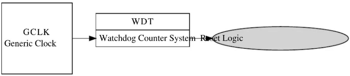
flowchart
graph LR
A["GCLK Generic Clock"] --> B["WDT"]
B --> C["Watchdog Counter System"]
C --> D["Reset Logic"]
21.3 Special Considerations
On some devices the Watchdog configuration can be fused to be always on in a particular configuration; if this mode is enabled the Watchdog is not software configurable and can have its count reset and early warning state checked/cleared only.
21.4 Extra Information
For extra information see Extra Information for WDT Driver. This includes:
• Acronyms
- Dependencies
- Errata
- Module History
21.5 Examples
For a list of examples related to this driver, see Examples for WDT Driver.
21.6 API Overview
21.6.1 Variable and Type Definitions
21.6.1.1 Callback configuration and initialization
Type wdt_callback_t
typedef void(* wdt_callback_t )(void)
Type definition for a WDT module callback function.
21.6.2 Structure Definitions
21.6.2.1 Struct wdt\_conf
Configuration structure for a Watchdog Timer instance. This structure should be initialized by the wdt_get_config_defaults() function before being modified by the user application.
Table 21-1. Members
| Type Name Description | ||
| bool always_on If true, the Watchdog will be locked | to the current configuration settings when the Watchdog is enabled. | |
| enum gclk_generator clock_source GCLK generator used to clock the | peripheral | |
| enum wdt_period early_warning_period Number of Watchdog timer clock | ticks until the early warning flag is set. | |
| bool enable Enable/Disable the Watchdog | Timer | |
| enum wdt_period timeout_period Number of Watchdog timer clock | ticks until the Watchdog expires. | |
| enum wdt_period window_period Number of Watchdog timer clock | ticks until the reset window opens. | |
21.6.3 Function Definitions
21.6.3.1 Configuration and initialization
Function wdt\_is\_syncing()
Determines if the hardware module(s) are currently synchronizing to the bus.
bool wdt_is_syncing(void)
Checks to see if the underlying hardware peripheral module(s) are currently synchronizing across multiple clock domains to the hardware bus. This function can be used to delay further operations on a module until such time that it is ready, to prevent blocking delays for synchronization in the user application.
Returns
Synchronization status of the underlying hardware module(s).
Table 21-2. Return Values
| Return value Description | |
| true | if the module has completed synchronization |
| false | if the module synchronization is ongoing |
Function wdt\_get\_config\_defaults()
Initializes a Watchdog Timer configuration structure to defaults.
void wdt_get_config_defaults(
struct wdt_conf *const config)
Initializes a given Watchdog Timer configuration structure to a set of known default values. This function should be called on all new instances of these configuration structures before being modified by the user application.
The default configuration is as follows:
- Not locked, to allow for further (re-)configuration
- Enable WDT
• Watchdog timer sourced from Generic Clock Channel 4
• A timeout period of 16384 clocks of the Watchdog module clock - No window period, so that the Watchdog count can be reset at any time
- No early warning period to indicate the Watchdog will soon expire
Table 21-3. Parameters
| Data direction Parameter name Description | |
| [out] config Configuration structure to initialize | to default values |
Function wdt\_set\_config()
Sets up the WDT hardware module based on the configuration.
enum status_code wdt_set_config(
const struct wdt_conf *const config)
Writes a given configuration of a WDT configuration to the hardware module, and initializes the internal device struct
Table 21-4. Parameters
| Data direction Parameter name Description | |
| [in] config Pointer to the configuration struct |
Returns
Status of the configuration procedure.
Table 21-5. Return Values
| Return value Description | |
| STATUS_OK If the module was configured correctly | |
| STATUS_ERR_INVALID_ARG If invalid argument(s) were supplied | |
| STATUS_ERR_IO If the Watchdog module is locked to be always on |
Function wdt\_is\_locked()
Determines if the Watchdog timer is currently locked in an enabled state.
bool wdt_is_locked(void)
Determines if the Watchdog timer is currently enabled and locked, so that it cannot be disabled or otherwise reconfigured.
Returns
Current Watchdog lock state.
21.6.3.2 Timeout and Early Warning Management
Function wdt\_clear\_early\_warning()
Clears the Watchdog timer Early Warning period elapsed flag.
void wdt_clear_early_warning(void)
Clears the Watchdog timer Early Warning period elapsed flag, so that a new early warning period can be detected.
Function wdt\_is\_early\_warning()
Determines if the Watchdog timer Early Warning period has elapsed.
bool wdt_is_early_warning(void)
Determines if the Watchdog timer Early Warning period has elapsed.
Note
If no early warning period was configured, the value returned by this function is invalid.
Returns
Current Watchdog Early Warning state.
Function wdt\_reset\_count()
Resets the count of the running Watchdog Timer that was previously enabled.
void wdt_reset_count(void)
Resets the current count of the Watchdog Timer, restarting the timeout period count elapsed. This function should be called after the window period (if one was set in the module configuration) but before the timeout period to prevent a reset of the system.
21.6.3.3 Callback configuration and initialization
Function wdt\_register\_callback()
Registers an asynchronous callback function with the driver.
enum status_code wdt_register_callback( const wdt_callback_t callback,
const enum wdt_callback type)
Registers an asynchronous callback with the WDT driver, fired when a given criteria (such as an Early Warning) is met. Callbacks are fired once for each event.
Table 21-6. Parameters
| Data direction Parameter name Description | |
| [in] callback Pointer to the callback function to | register |
| [in] type Type of callback function to register |
Returns
Status of the registration operation.
Table 21-7. Return Values
| Return value Description | |
| STATUS_OK The callback was registered successfully. | |
| STATUS_ERR_INVALID_ARG If an invalid callback type was supplied. | |
Function wdt\_unregister\_callback()
Unregisters an asynchronous callback function with the driver.
enum status_code wdt_unregister_callback( const enum wdt_callback type)
Unregisters an asynchronous callback with the WDT driver, removing it from the internal callback registration table.
Table 21-8. Parameters
| Data direction Parameter name Description | |
| [in] type Type of callback function to | |
| unregister |
Returns
Status of the de-registration operation.
Table 21-9. Return Values
| Return value Description | |
| STATUS_OK The callback was Unregistered successfully. | |
| STATUS_ERR_INVALID_ARG If an invalid callback type was supplied. | |
21.6.3.4 Callback enabling and disabling
Function wdt\_enable\_callback()
Enables asynchronous callback generation for a given type.
enum status_code wdt_enable_callback( const enum wdt_callback type)
Enables asynchronous callbacks for a given callback type. This must be called before an external interrupt channel will generate callback events.
Table 21-10. Parameters
| Data direction Parameter name Description | |
| [in] type Type of callback function to enable |
Returns
Status of the callback enable operation.
Table 21-11. Return Values
| Return value Description | |
| STATUS_OK The callback was enabled successfully. | |
| STATUS_ERR_INVALID_ARG If an invalid callback type was supplied. | |
Function wdt\_disable\_callback()
Disables asynchronous callback generation for a given type.
enum status_code wdt_disable_callback( const enum wdt_callback type)
Disables asynchronous callbacks for a given callback type.
Table 21-12. Parameters
| Data direction Parameter name Description | |
| [in] type Type of callback function to disable |
Returns
Status of the callback disable operation.
Table 21-13. Return Values
| Return value Description | |
| STATUS_OK The callback was disabled successfully. | |
| STATUS_ERR_INVALID_ARG If an invalid callback type was supplied. | |
21.6.4 Enumeration Definitions
21.6.4.1 Callback configuration and initialization
Enum wdt\_callback
Enum for the possible callback types for the WDT module.
Table 21-14. Members
| Enum value Description | |
| WDT_CALLBACK_EARLY_WARNING Callback type for when an early warningcallback from the WDT module is issued. | |
21.6.4.2 Enum wdt\_period
Enum for the possible period settings of the Watchdog timer module, for values requiring a period as a number of Watchdog timer clock ticks.
Table 21-15. Members
| Enum value Description | |
| WDT_PERIOD_NONE No Watchdog period. This value can only be used when setting the Window and Early Warning periods; its use as the Watchdog Reset Period is invalid. | |
| WDT_PERIOD_8CLK Watchdog period of 8 clocks of the Watchdog Timer Generic Clock. | |
| WDT_PERIOD_16CLK Watchdog period of 16 clocks of the Watchdog Timer Generic Clock. | |
| WDT_PERIOD_32CLK Watchdog period of 32 clocks of the Watchdog Timer Generic Clock. | |
| WDT_PERIOD_64CLK Watchdog period of 64 clocks of the Watchdog Timer Generic Clock. | |
| WDT_PERIOD_128CLK Watchdog period of 128 clocks of the Watchdog Timer Generic Clock. | |
| WDT_PERIOD_256CLK Watchdog period of 256 clocks of the Watchdog Timer Generic Clock. | |
| WDT_PERIOD_512CLK Watchdog period of 512 clocks of the Watchdog Timer Generic Clock. | |
| WDT_PERIOD_1024CLK Watchdog period of 1024 clocks of the Watchdog Timer Generic Clock. | |
| WDT_PERIOD_2048CLK Watchdog period of 2048 clocks of the Watchdog Timer Generic Clock. | |
| WDT_PERIOD_4096CLK Watchdog period of 4096 clocks of the Watchdog Timer Generic Clock. | |
| WDT_PERIOD_8192CLK Watchdog period of 8192 clocks of the Watchdog Timer Generic Clock. | |
| WDT_PERIOD_16384CLK Watchdog period of 16384 clocks of the Watchdog Timer Generic Clock. | |
21.7 Extra Information for WDT Driver
21.7.1 Acronyms
The table below presents the acronyms used in this module:
| Acronym Description | |
| WDT Watchdog Timer |
21.7.2 Dependencies
This driver has the following dependencies:
- System Clock Driver
21.7.3 Errata
There are no errata related to this driver.
21.7.4 Module History
An overview of the module history is presented in the table below, with details on the enhancements and fixes made to the module since its first release. The current version of this corresponds to the newest version in the table.
Changelog
Add SAMD21 support and driver updated to follow driver type convention:
- wdt_init, wdt_enable, wdt_disable functions removed
- wdt_set_config function added
- WDT module enable state moved inside the configuration struct
Initial Release
21.8 Examples for WDT Driver
This is a list of the available Quick Start guides (QSGs) and example applications for SAM D20/D21 Watchdog Driver (WDT). QSGs are simple examples with step-by-step instructions to configure and use this driver in a selection of use cases. Note that QSGs can be compiled as a standalone application or be added to the user application.
- Quick Start Guide for WDT - Basic
- Quick Start Guide for WDT - Callback
21.8.1 Quick Start Guide for WDT - Basic
In this use case, the Watchdog module is configured for:
- System reset after 2048 clocks of the Watchdog generic clock
• Always on mode disabled - Basic mode, with no window or early warning periods
This use case sets up the Watchdog to force a system reset after every 2048 clocks of the Watchdog's Generic Clock channel, unless the user periodically resets the Watchdog counter via a button before the timer expires. If the watchdog resets the device, a LED on the board is turned off.
21.8.1.1 Setup
Prerequisites
There are no special setup requirements for this use-case.
Code
Copy-paste the following setup code to your user application:
void configure_wdt(void)
{
/* Create a new configuration structure for the Watchdog settings and fill
* with the default module settings. */
struct wdt_conf config_wdt;
wdt_get_config_defaults(&config_wdt);
/* Set the Watchdog configuration settings */
config_wdt.always_on = false;
config_wdt.clock_source = GCLK_GENERATOR_4;
config_wdt.timeout_period = WDT_PERIOD_2048CLK;
/* Initialize and enable the Watchdog with the user settings */
wdt_set_config(&config_wdt);
}
Add to user application initialization (typically the start of main():
configure_wdt();
Workflow
- Create a Watchdog module configuration struct, which can be filled out to adjust the configuration of the Watchdog.
struct wdt_conf config_wdt;
- Initialize the Watchdog configuration struct with the module's default values.
wdt_get_config_defaults(&config_wdt);
Note
This should always be performed before using the configuration struct to ensure that all values are initialized to known default settings.
- Adjust the configuration struct to set the timeout period and lock mode of the Watchdog.
config_wdt.always_on = false;
config_wdt.clock_source = GCLK_GENERATOR_4;
config_wdt.timeout_period = WDT_PERIOD_2048CLK;
- Setups the WDT hardware module with the requested settings.
wdt_set_config(&config_wdt);
21.8.1.2 Quick Start Guide for WDT - Basic
Code
Copy-paste the following code to your user application:
enum system_reset_cause reset_cause = system_get_reset_cause();
if (reset_cause == SYSTEM_RESET_CAUSE_WDT) {
port_pin_set_output_level(LED_0_PIN, LED_0_INACTIVE);
}
else {
port_pin_set_output_level(LED_0_PIN, LED_0_ACTIVE);
}
while (true) {
if (port_pin_get_input_level(BUTTON_0_PIN) == false) {
port_pin_set_output_level(LED_0_PIN, LED_0_ACTIVE);
wdt_reset_count();
}
Workflow
- Retrieve the cause of the system reset to determine if the watchdog module was the cause of the last reset.
enum system_reset_cause reset_cause = system_get_reset_cause();
- Turn on or off the board LED based on whether the watchdog reset the device.
if (reset_cause == SYSTEM_RESET_CAUSE_WDT) {
port_pin_set_output_level(LED_0_PIN, LED_0_INACTIVE);
}
else {
port_pin_set_output_level(LED_0_PIN, LED_0_ACTIVE);
}
- Enter an infinite loop to hold the main program logic.
while (true) {
- Test to see if the board button is currently being pressed.
if (port_pin_get_input_level(BUTTON_0_PIN) == false) {
- If the button is pressed, turn on the board LED and reset the Watchdog timer.
port_pin_set_output_level(LED_0_PIN, LED_0_ACTIVE);
wdt_reset_count();
21.8.2 Quick Start Guide for WDT - Callback
In this use case, the Watchdog module is configured for:
- System reset after 4096 clocks of the Watchdog generic clock
• Always on mode disabled - Early warning period of 2048 clocks of the Watchdog generic clock
This use case sets up the Watchdog to force a system reset after every 4096 clocks of the Watchdog's Generic Clock channel, with an Early Warning callback being generated every 2048 clocks. Each time the Early Warning interrupt fires the board LED is turned on, and each time the device resets the board LED is turned off, giving a periodic flashing pattern.
21.8.2.1 Setup
Prerequisites
There are no special setup requirements for this use-case.
Code
Copy-paste the following setup code to your user application:
void watchdog_early_warning_callback(void)
{
port_pin_set_output_level(LED_0_PIN, LED_0_ACTIVE);
}
void configure_wdt(void)
{
/* Create a new configuration structure for the Watchdog settings and fill
* with the default module settings. */
struct wdt_conf config_wdt;
wdt_get_config_defaults(&config_wdt);
/* Set the Watchdog configuration settings */
config_wdt.always_on = false;
config_wdt.clock_source = GCLK_GENERATOR_4;
config_wdt.timeout_period = WDT_PERIOD_4096CLK;
config_wdt.early_warning_period = WDT_PERIOD_2048CLK;
/* Initialize and enable the Watchdog with the user settings */
wdt_set_config(&config_wdt);
}
void configure_wdt_callbacks(void)
{
wdt_register_callback(watchdog_early_warning_callback,
WDT_CALLBACK_EARLY_WARNING);
wdt_enable_callback(WDT_CALLBACK_EARLY_WARNING);
}
Add to user application initialization (typically the start of main()):
configure_wdt();
configure_wdt_callbacks();
Workflow
- Configure and enable the Watchdog driver
a. Create a Watchdog module configuration struct, which can be filled out to adjust the configuration of the Watchdog.
struct wdt_conf config_wdt;
b. Initialize the Watchdog configuration struct with the module's default values.
wdt_get_config_defaults(&config_wdt);
Note
This should always be performed before using the configuration struct to ensure that all values are initialized to known default settings.
c. Adjust the configuration struct to set the timeout and early warning periods of the Watchdog.
config_wdt.always_on = false;
config_wdt.clock_source = GCLK_GENERATOR_4;
config_wdt.timeout_period = WDT_PERIOD_4096CLK;
config_wdt.early_warning_period = WDT_PERIOD_2048CLK;
d. Sets up the WDT hardware module with the requested settings.
wdt_set_config(&config_wdt);
- Register and enable the Early Warning callback handler
a. Register the user-provided Early Warning callback function with the driver, so that it will be run when an Early Warning condition occurs.
wdt_register_callback(watchdog_early_warning_callback, WDT_CALLBACK_EARLY_WARNING);
b. Enable the Early Warning callback so that it will generate callbacks.
wdt_enable_callback(WDT_CALLBACK_EARLY_WARNING);
21.8.2.2 Quick Start Guide for WDT - Callback
Code
Copy-paste the following code to your user application:
port_pin_set_output_level(LED_0_PIN, LED_0_INACTIVE);
system_interrupt_enable_global();
while (true) {
/* Wait for callback */
}
Workflow
- Turn off the board LED when the application starts.
port_pin_set_output_level(LED_0_PIN, LED_0_INACTIVE);
- Enable global interrupts so that callbacks can be generated.
system_interrupt_enable_global();
- Enter an infinite loop to hold the main program logic.
while (true) {
/* Wait for callback */
}
22. SAM D21 Direct Memory Access Controller Driver (DMAC)
This driver for SAM D21 devices provides an interface for the configuration and management of the Direct Memory Access Controller(DMAC) module within the device. The DMAC can transfer data between memories and peripherals, and thus off-load these tasks from the CPU. The module supports peripheral to peripheral, peripheral to memory, memory to peripheral and memory to memory transfers.
The following peripherals are used by the DMAC Driver:
• DMAC (Direct Memory Access Controller)
The outline of this documentation is as follows:
- Prerequisites
- Module Overview
• Special Considerations - Extra Information
- Examples
- API Overview
22.1 Prerequisites
There are no prerequisites for this module.
22.2 Module Overview
SAM D21 devices with DMAC enables high data transfer rates with minimum CPU intervention and frees up CPU time. With access to all peripherals, the DMAC can handle automatic transfer of data to/from modules. It supports static and incremental addressing for both source and destination.
The DMAC when used with Event System or peripheral triggers, provides a considerable advantage by reducing the power consumption and performing data transfer in the background. For example if the ADC is configured to generate an event, it can trigger the DMAC to transfer the data into another peripheral or into SRAM. The CPU can remain in sleep during this time to reduce power consumption.
The DMAC module has 12 channels. The DMA channel operation can be suspended at any time by software, by events from event system, or after selectable descriptor execution. The operation can be resumed by software or by events from event system. The DMAC driver for SAM D21 supports four types of transfers such as peripheral to peripheral, peripheral to memory, memory to peripheral and memory to memory.
The basic transfer unit is a beat which is defined as a single bus access. There can be multiple beats in a single block transfer and multiple block transfers in a DMA transaction. DMA transfer is based on descriptors, which holds transfer properties such as the source and destination addresses, transfer counter and other additional transfer control information. The descriptors can be static or linked. When static, a single block transfer is performed. When linked, a number of transfer descriptors can be used to enable multiple block transfers within a single DMA transaction.
The implementation of the DMA driver is based on the idea that DMA channel is a finite resource of entities with the same abilities. A DMA channel resource is able to move a defined set of data from a source address to destination address triggered by a transfer trigger. On the SAM D21 devices there are 12 DMA resources available for allocation. Each of these DMA resources can trigger interrupt callback routines and peripheral events. The other main features are
- Selectable transfer trigger source
- Software
- Event System
- Peripheral
• Event input and output is supported for the 4 lower channels
• 4 level channel priority
- Optional interrupt generation on transfer complete, channel error or channel suspend
• Supports multi-buffer or circular buffer mode by linking multiple descriptors
- Beat size configurable as 8-bit, 16-bit or 32-bit
A simplified block diagram of the DMA Resource can be seen in Figure 22-1: Module Overview on page 509.
Figure 22-1. Module Overview

flowchart
graph TD
A["Transfer Trigger DMA Channel"] --> B["Transfer Descriptor"]
B --> C["Interrupt"]
B --> D["Events"]
22.2.1 Terminology Used in DMAC Transfers
| Name Description | |
| Beat It is a single bus access by the DMAC. Configurable | as 8-bit, 16-bit or 32-bit |
| Burst It is a transfer of n-beats (n=1,4,8,16). For the DMAC | module in SAM D21, the burst size is one beat.Arbitration takes place each time a burst transfer is completed |
| Block transfer A single block transfer is a configurable number of (1 to 64k) beat transfers | |
22.2.2 DMA Channels
The DMAC in each device consists of several DMA channels, which along with the transfer descriptors defines the data transfer properties.
- The transfer control descriptor defines the source and destination addresses, source and destination address increment settings, the block transfer count and event output condition selection.
• Dedicated channel registers control the peripheral trigger source, trigger mode settings, event input actions and channel priority level settings.
With a successful DMA resource allocation, a dedicated DMA channel will be assigned. The channel will be occupied until the DMA resource is freed. A DMA resource handle is used to identify the specific DMA resource. When there are multiple channels with active requests, the arbiter prioritizes the channels requesting access to the bus.
22.2.3 DMA Triggers
DMA transfer can be started only when a DMA transfer request is acknowledged/granted by the arbiter. A transfer request can be triggered from software, peripheral or an event. There are dedicated source trigger selections for each DMA channel usage.
22.2.4 DMA Transfer Descriptor
The transfer descriptor resides in the SRAM and defines these channel properties.
| Field Name Field Width | |
| Descriptor Next Address 32 Bits | |
| Destination Address 32 Bits | |
| Source Address 32 Bits | |
| Block Transfer Counter 16 Bits | |
| Block Transfer Control 16 Bits |
Before starting a transfer, at least one descriptor should be configured. After a successful allocation of a DMA channel, the transfer descriptor can be added with a call to dma_add_descriptor(). If there is a transfer descriptor already allocated to the DMA resource, the descriptor will be linked to the next descriptor address.
22.2.5 DMA Interrupts/Events
Both an interrupt callback and an peripheral event can be triggered by the DMA transfer. Three types of callbacks are supported by the DMA driver: transfer complete, channel suspend and transfer error. Each of these callback types can be registered and enabled for each channel independently through the DMA driver API.
The DMAC module can also generate events on transfer complete. Event generation is enabled through the DMA channel, event channel configuration and event user multiplexing is done through the events driver.
The DMAC can generate events in the below cases:
- When a block transfer is complete
- When each beat transfer within a block transfer is complete
22.3 Special Considerations
There are no special considerations for this module.
22.4 Extra Information
For extra information see Extra Information for DMAC Driver. This includes:
- Acronyms
- Dependencies
- Errata
- Module History
22.5 Examples
For a list of examples related to this driver, see Examples for DMAC Driver.
22.6 API Overview
22.6.1 Variable and Type Definitions
22.6.1.1 Type dma_callback_t
typedef void(* dma_callback_t )(const struct dma_resource *const resource)
Type definition for a DMA resource callback function
22.6.1.2 Variable descriptor\_section
DmacDescriptor descriptor_section
ExInitial description section
22.6.2 Structure Definitions
22.6.2.1 Struct dma\_descriptor\_config
DMA transfer descriptor configuration. When the source or destination address increment is enabled, the addresses stored into the configuration structure must correspond to the end of the transfer.
Table 22-1. Members
| Type Name Description | ||
| enum dma_beat_size beat_size Beat size is configurable as 8-bit, | 16-bit or 32-bit | |
| enum dma_block_action block_action Action taken when a block transfer | is completed | |
| uint16_t block_transfer_count It is the number of beats in a block. | This count value is decremented by one after each beat data transfer | |
| bool descriptor_valid Descriptor valid flag used to | identify whether a descriptor is valid or not | |
| uint32_t destination_address Transfer destination address | ||
| bool dst_increment_enable Used for enabling the destination | address increment | |
| enum dma_event_output_selection | event_output_selection | This is used to generate an event on specific transfer action in a channel. Supported only in four lower channels |
| uint32_t next_descriptor_address | Set to zero for static descriptors.This must have a valid memory address for linked descriptors | |
| uint32_t source_address | Transfer source address | |
| bool src_increment_enable Used for enabling the source | address increment | |
| enum dma_step_selection | step_selection | This bit selects whether the source or destination address is using the step size settings |
| enum dma_address_increment_stepsize | step_size | The step size for source/destination address increment.The next address is calculated asnext_addr = addr + (2^step_size * beat size) |
22.6.2.2 Struct dma\_events\_config
Configurations for DMA events
Table 22-2. Members
| Type Name Description | ||
| bool event_output_enable Enable DMA event output | ||
| enum dma_event_input_action input_action Event input actions |
22.6.2.3 Struct dma\_resource
Structure for DMA transfer resource
Table 22-3. Members
| Type Name Description | ||
| dma_callback_t callback[] Array of callback functions for DMA | transfer job | |
| uint8_t callback_enable Bit mask for enabled callbacks | ||
| uint8_t channel_id Allocated DMA channel ID | ||
| DmacDescriptor * descriptor DMA transfer descriptor | ||
| enum status_code job_status | Status of the last job | |
| uint32_t | transferred_size | Transferred data size |
22.6.2.4 Struct dma\_resource\_config
DMA configurations for transfer
Table 22-4. Members
| Type Name Description | ||
| struct dma_events_config | event_config | DMA events configurations |
| uint8_t peripheral_trigger DMA peripheral trigger index | ||
| enum dma_priority_level | priority DMA transfer priority | |
| enum dma_transfer_trigger_action | trigger_action | DMA trigger action |
22.6.3 Macro Definitions
22.6.3.1 Macro DMA\_INVALID\_CHANNEL
#define DMA_INVALID_CHANNEL 0xff
DMA invalid channel number
22.6.4 Function Definitions
22.6.4.1 Function dma_abort_job()
Abort a DMA transfer.
void dma_abort_job(
struct dma_resource * resource)
This function will abort a DMA transfer. The DMA channel used for the DMA resource will be disabled. The block transfer count will be also calculated and written to the DMA resource structure.
Note
The DMA resource will not be freed after calling this function. The function dma_free() can be used to free an allocated resource.
Table 22-5. Parameters
| Data direction Parameter name Description | |
| [in, out] resource Pointer to the DMA resource |
22.6.4.2 Function dma_add_descriptor()
Add a DMA transfer descriptor to a DMA resource.
enum status_code dma_add_descriptor(
struct dma_resource * resource,
DmacDescriptor * descriptor)
This function will add a DMA transfer descriptor to a DMA resource. If there was a transfer descriptor already allocated to the DMA resource, the descriptor will be linked to the next descriptor address.
Table 22-6. Parameters
| Data direction Parameter name Description | |
| [in] resource Pointer to the DMA resource | |
| [in] descriptor Pointer to the transfer descriptor |
Table 22-7. Return Values
| Return value Description | |
| STATUS_OK The descriptor is added to the DMA resource | |
| STATUS_BUSY The DMA resource was busy and the descriptor is not added | |
22.6.4.3 Function dma_allocate()
Allocate a DMA with configurations.
enum status_code dma_allocate(
struct dma_resource * resource,
struct dma_resource_config * config)
This function will allocate a proper channel for a DMA transfer request.
Table 22-8. Parameters
| Data direction Parameter name Description | |
| [in, out] dma_resource Pointer to a DMA resource | instance |
| [in] transfer_config Configurations of the DMA transfer |
Returns
Status of the allocation procedure.
Table 22-9. Return Values
| Return value Description | |
| STATUS_OK The DMA resource was allocated successfully | |
| STATUS_ERR_NOT_FOUND DMA resource allocation failed | |
22.6.4.4 Function dma\_descriptor\_create()
Create a DMA transfer descriptor with configurations.
void dma_descriptor_create(
DmacDescriptor * descriptor,
struct dma_descriptor_config * config)
This function will set the transfer configurations to the DMA transfer descriptor.
Table 22-10. Parameters
| Data direction Parameter name Description | |
| [in] descriptor Pointer to the DMA transfer | descriptor |
| [in] config Pointer to the descriptor | configuration structure |
22.6.4.5 Function dma\_descriptor\_get\_config\_defaults()
Initializes DMA transfer configuration with predefined default values.
void dma_descriptor_get_config_defaults( struct dma_descriptor_config * config)
This function will initialize a given DMA descriptor configuration structure to a set of known default values. This function should be called on any new instance of the configuration structure before being modified by the user application.
The default configuration is as follows:
- Set the descriptor as valid
-
Disable event output
-
No block action
- Set beat size as byte
- Enable source increment
- Enable destination increment
- Step size is applied to the destination address
- Address increment is beat size multiplied by 1
- Default transfer size is set to 0
- Default source address is set to NULL
- Default destination address is set to NULL
- Default next descriptor not available
Table 22-11. Parameters
| Data direction Parameter name Description | |
| [out] config Pointer to the configuration |
22.6.4.6 Function dma\_disable\_callback()
Disable a callback function for a dedicated DMA resource.
void dma_disable_callback(
struct dma_resource * resource,
enum dma_callback_type type)
Table 22-12. Parameters
| Data direction Parameter name Description | |
| [in] resource Pointer to the DMA resource | |
| [in] type Callback function type |
22.6.4.7 Function dma\_enable\_callback()
Enable a callback function for a dedicated DMA resource.
void dma_enable_callback(
struct dma_resource * resource,
enum dma_callback_type type)
Table 22-13. Parameters
| Data direction Parameter name Description | |
| [in] resource Pointer to the DMA resource | |
| [in] type Callback function type |
22.6.4.8 Function dma\_free()
Free an allocated DMA resource.
enum status_code dma_free(
struct dma_resource * resource)
This function will free an allocated DMA resource.
Table 22-14. Parameters
| Data direction Parameter name Description | |
| [in, out] resource Pointer to the DMA resource |
Returns
Status of the free procedure.
Table 22-15. Return Values
| Return value Description | |
| STATUS_OK The DMA resource was freed successfully | |
| STATUS_BUSY The DMA resource was busy and can't be freed | |
| STATUS_ERR_NOT_INITIALIZED DMA resource was not initialized |
22.6.4.9 Function dma\_get\_config\_defaults()
Initializes config with predefined default values.
void dma_get_config_defaults(
struct dma_resource_config * config)
This function will initialize a given DMA configuration structure to a set of known default values. This function should be called on any new instance of the configuration structure before being modified by the user application.
The default configuration is as follows:
- Software trigger is used as the transfer trigger
- Priority level 0
- Only software/event trigger
- Requires a trigger for each transaction
- No event input /output
Table 22-16. Parameters
| Data direction Parameter name Description | |
| [out] config Pointer to the configuration |
22.6.4.10 Function dma\_get\_job\_status()
Get DMA resource status.
enum status_code dma_get_job_status(
struct dma_resource * resource)
Table 22-17. Parameters
| Data direction Parameter name Description | |
| [in] resource Pointer to the DMA resource |
Returns
Status of the DMA resource.
22.6.4.11 Function dma\_is\_busy()
Check if the given DMA resource is busy.
bool dma_is_busy(
struct dma_resource * resource)
Table 22-18. Parameters
| Data direction Parameter name Description | |
| [in] resource Pointer to the DMA resource |
Returns
Status which indicates whether the DMA resource is busy.
Table 22-19. Return Values
| Return value Description | |
| true The DMA resource has an on-going transfer | |
| false The DMA resource is not busy |
22.6.4.12 Function dma\_register\_callback()
Register a callback function for a dedicated DMA resource.
void dma_register_callback(
struct dma_resource * resource,
dma_callback_t callback,
enum dma_callback_type type)
There are three type of callback functions, which can be registered
- Callback for transfer complete
- Callback for transfer error
- Callback for channel suspend
Table 22-20. Parameters
| Data direction Parameter name Description | |
| [in] resource Pointer to the DMA resource |
Data direction Parameter name Description
[in] callback Pointer to the callback function
[in] type Callback function type
22.6.4.13 Function dma\_reset\_descriptor()
Reset DMA descriptor.
void dma_reset_descriptor(
struct dma_resource * resource)
This function will clear the DESCADDR register of an allocated DMA resource.
22.6.4.14 Function dma\_resume\_job()
Resume a suspended DMA transfer.
void dma_resume_job(
struct dma_resource * resource)
This function try to resume a suspended transfer of a DMA resource.
Table 22-21. Parameters
Data direction Parameter name Description
| [in] resource Pointer to the DMA resource |
22.6.4.15 Function dma\_start\_transfer\_job()
Start a DMA transfer.
enum status_code dma_start_transfer_job( struct dma_resource * resource)
This function will start a DMA transfer through an allocated DMA resource.
Table 22-22. Parameters
Data direction Parameter name Description
| [in, out] resource Pointer to the DMA resource |
Returns
Status of the transfer start procedure
Table 22-23. Return Values
| Return value Description | |
| STATUS_OK The transfer was started successfully | |
| STATUS_BUSY The DMA resource was busy and the transfer was not started | |
Return value Description
STATUS_ERR_INVALID_ARG Transfer size is 0 and transfer was not started
22.6.4.16 Function dma\_suspend\_job()
Suspend a DMA transfer.
void dma_suspend_job(
struct dma_resource * resource)
This function will request to suspend the transfer of the DMA resource. The channel is kept enabled, can receive transfer triggers (the transfer pending bit will be set), but will be removed from the arbitration scheme. The channel operation can be resumed by calling dma_resume_job().
Note
This function sets the command to suspend the DMA channel associated with a DMA resource. The channel suspend interrupt flag indicates whether the transfer is truly suspended.
Table 22-24. Parameters
| Data direction Parameter name Description | |
| [in] resource Pointer to the DMA resource |
22.6.4.17 Function dma\_trigger\_transfer()
Will set a software trigger for resource.
void dma_trigger_transfer(
struct dma_resource * resource)
This function is used to set a software trigger on the DMA channel associated with resource. If a trigger is already pending no new trigger will be generated for the channel.
Table 22-25. Parameters
| Data direction Parameter name Description | |
| [in] resource Pointer to the DMA resource |
22.6.4.18 Function dma\_unregister\_callback()
Unregister a callback function for a dedicated DMA resource.
void dma_unregister_callback(
struct dma_resource * resource,
enum dma_callback_type type)
There are three type of callback functions,
- Callback for transfer complete
- Callback for transfer error
- Callback for channel suspend
The application can unregister any of the callback functions which are already registered and are no longer needed.
Table 22-26. Parameters
| Data direction Parameter name Description | |
| [in] resource Pointer to the DMA resource | |
| [in] type Callback function type |
22.6.4.19 Function dma\_update\_descriptor()
Update DMA descriptor.
void dma_update_descriptor(
struct dma_resource * resource,
DmacDescriptor * descriptor)
This function can update the descriptor of an allocated DMA resource.
22.6.5 Enumeration Definitions
22.6.5.1 Enum dma\_address\_increment\_stepsize
Address increment step size. These bits select the address increment step size. The setting apply to source or destination address, depending on STEPSEL setting.
Table 22-27. Members
| Enum value Description | |
| DMA_ADDRESS_INCREMENT_STEP_SIZE_1 The address is incremented by (beat size * 1) | |
| DMA_ADDRESS_INCREMENT_STEP_SIZE_2 The address is incremented by (beat size * 2) | |
| DMA_ADDRESS_INCREMENT_STEP_SIZE_4 The address is incremented by (beat size * 4) | |
| DMA_ADDRESS_INCREMENT_STEP_SIZE_8 The address is incremented by (beat size * 8) | |
| DMA_ADDRESS_INCREMENT_STEP_SIZE_16 The address is incremented by (beat size * 16) | |
| DMA_ADDRESS_INCREMENT_STEP_SIZE_32 The address is incremented by (beat size * 32) | |
| DMA_ADDRESS_INCREMENT_STEP_SIZE_64 The address is incremented by (beat size * 64) | |
| DMA_ADDRESS_INCREMENT_STEP_SIZE_128 The address is incremented by (beat size * 128) | |
22.6.5.2 Enum dma\_beat\_size
The basic transfer unit in DMAC is a beat, which is defined as a single bus access. Its size is configurable and applies to both read and write
Table 22-28. Members
| Enum value Description | |
| DMA_BEAT_SIZE_BYTE 8-bit access | |
| DMA_BEAT_SIZE_HWORD | 16-bit access |
| DMA_BEAT_SIZE_WORD | 32-bit access |
22.6.5.3 Enum dma_block_action
Block action definitions.
Table 22-29. Members
| Enum value Description | |
| DMA_BLOCK_ACTION_NOACT No action | |
| DMA_BLOCK_ACTION_INT Channel in normal operation and sets transfercomplete interrupt flag after block transfer | |
| DMA_BLOCK_ACTION_SUSPEND Trigger channel suspend after block transferand sets channel suspend interrupt flag oncethe channel is suspended | |
| DMA_BLOCK_ACTION_BOTH Sets transfer complete interrupt flag after ablock transfer and trigger channel suspend. Thechannel suspend interrupt flag will be set oncethe channel is suspended | |
22.6.5.4 Enum dma\_callback\_type
Callback types for DMA callback driver.
Table 22-30. Members
| Enum value Description | |
| DMA_CALLBACK_TRANSFER_DONE Callback for transfer complete | |
| DMA_CALLBACK_TRANSFER_ERROR Callback for any of transfer errors. A transfer error is flagged if a bus error is detected during an AHB access or when the DMAC fetches an invalid descriptor | |
| DMA_CALLBACK_CHANNEL_SUSPEND Callback for channel suspend | |
| DMA_CALLBACK_N Number of available callbacks | |
22.6.5.5 Enum dma\_event\_input\_action
DMA input actions.
Table 22-31. Members
| Enum value Description | |
| DMA_EVENT_INPUT_NOACT No action | |
| DMA_EVENT_INPUT_TRIG Normal transfer and periodic transfer trigger | |
| DMA_EVENT_INPUT_CTRIG Conditional transfer trigger | |
| DMA_EVENT_INPUT_CBLOCK Conditional block transfer | |
| DMA_EVENT_INPUT_SUSPEND | Channel suspend operation |
| DMA_EVENT_INPUT_RESUME | Channel resume operation |
| DMA_EVENT_INPUT_SSKIP | Skip next block suspend action |
22.6.5.6 Enum dma\_event\_output\_selection
Event output selection.
Table 22-32. Members
| Enum value Description | |
| DMA_EVENT_OUTPUT_DISABLE Event generation disable | |
| DMA_EVENT_OUTPUT_BLOCK Event strobe when block transfer complete | |
| DMA_EVENT_OUTPUT_RESERVED Event output reserved | |
| DMA_EVENT_OUTPUT_BEAT Event strobe when beat transfer complete | |
22.6.5.7 Enum dma\_priority\_level
DMA priority level
Table 22-33. Members
| Enum value Description | |
| DMA_PRIORITY_LEVEL_0 Priority level 0 | |
| DMA_PRIORITY_LEVEL_1 Priority level 1 | |
| DMA_PRIORITY_LEVEL_2 Priority level 2 | |
| DMA_PRIORITY_LEVEL_3 Priority level 3 |
22.6.5.8 Enum dma\_step\_selection
DMA step selection. This bit determines whether the step size setting is applied to source or destination address
Table 22-34. Members
| Enum value Description | |
| DMA_STEPSEL_DST Step size settings apply to the destination address | |
| DMA_STEPSEL_SRC Step size settings apply to the source address | |
22.6.5.9 Enum dma\_transfer\_trigger\_action
DMA trigger action type.
Table 22-35. Members
| Enum value Description | |
| DMA_TRIGGER_ACTON_BLOCK Perform a block transfer when triggered | |
| DMA_TRIGGER_ACTON_BEAT Perform a beat transfer when triggered | |
| DMA_TRIGGER_ACTON_TRANSACTION Perform a transaction when triggered | |
22.7 Extra Information for DMAC Driver
22.7.1 Acronyms
Below is a table listing the acronyms used in this module, along with their intended meanings.
| Acronym Description | |
| DMA Direct Memory Access | |
| DMAC Direct Memory Access Controller | |
| CPU Central Processing Unit |
22.7.2 Dependencies
This driver has the following dependencies:
• System Clock Driver
22.7.3 Errata
There are no errata related to this driver.
22.7.4 Module History
An overview of the module history is presented in the table below, with details on the enhancements and fixes made to the module since its first release. The current version of this corresponds to the newest version in the table.
Changelog
Initial Release
22.8 Examples for DMAC Driver
This is a list of the available Quick Start Guides (QSGs) and example applications for SAM D21 Direct Memory Access Controller Driver (DMAC). QSGs are simple examples with step-by-step instructions to configure and use this driver in a selection of use cases. Note that QSGs can be compiled as a standalone application or be added to the user application.
- Quick Start Guide for Memory to Memory
Note
More DMA usage examples are available in peripheral QSGs. A quick start guide for TC/TCC shows the usage of DMA event trigger; SERCOM SPI/USART/I2C has example for DMA transfer from peripheral to memory or from memory to peripheral; ADC/DAC shows peripheral to peripheral transfer.
22.8.1 Quick Start Guide for Memory to Memory
data transfer using DMAC
The supported device list:
- SAMD21
In this use case, the DMAC is configured for:
- Moving data from memory to memory
• Using software trigger
• Using DMA priority level 0
• Transaction as DMA trigger action
• No action on input events
• Output event not enabled
22.8.1.1 Setup
Prerequisites
There are no special setup requirements for this use-case.
Code
Copy-paste the following setup code to your user application:
#define DATA_LENGTH (1024)
static uint8_t source_memory[DATA_LENGTH];
static uint8_t destination_memory[DATA_LENGTH];
static volatile bool transfer_is_done = false;
COMPILER_ALIGNED(16)
DmacDescriptor example_descriptor;
static void transfer_done(const struct dma_resource* const resource)
{
transfer_is_done = true;
}
static void configure_dma_resource(struct dma_resource *resource)
{
struct dma_resource_config config;
dma_get_config_defaults(&config);
dma_allocate(resource, &config);
}
static void setup_transfer_descriptor(DmacDescriptor *descriptor)
{
struct dma_descriptor_config descriptor_config;
dma_descriptor_get_config_defaults(&descriptor_config);
descriptor_config.block_transfer_count = sizeof(source_memory);
descriptor_config.source_address = (uint32_t)source_memory + sizeof(source_memory);
descriptor_config.destination_address = (uint32_t)destination_memory + sizeof(source_memory);
dma_descriptor_createubescriptor, &descriptor_config);
}
Add the below section to user application initialization (typically the start of main()):
configure_dma_resource(&example_resource);
setup_transfer_descriptor(&example_descriptor);
dma_add_descriptor(&example_resource, &example_descriptor);
dma_register_callback(&example_resource, transfer_done,
DMA_CALLBACK_TRANSFER_DONE);
dma_enable_callback(&example_resource, DMA_CALLBACK_TRANSFER_DONE);
for (uint32_t i = 0; i < DATA_LENGTH; i++) {
source_memory[i] = i;
}
Workflow
- Create a DMA resource configuration structure, which can be filled out to adjust the configuration of a single DMA transfer.
struct dma_resource_config config;
- Initialize the DMA resource configuration struct with the module's default values.
dma_get_config_defaults(&config);
Note
This should always be performed before using the configuration struct to ensure that all values are initialized to known default settings.
- Allocate a DMA resource with the configurations.
dma_allocate(resource, &config);
- Declare a DMA transfer descriptor configuration structure, which can be filled out to adjust the configuration of a single DMA transfer.
struct dma_descriptor_config descriptor_config;
- Initialize the DMA transfer descriptor configuration struct with the module's default values.
dma_descriptor_get_config_defaults(&descriptor_config);
Note
This should always be performed before using the configuration struct to ensure that all values are initialized to known default settings.
- Set the specific parameters for a DMA transfer with transfer size, source address, destination address. In this example, we have enabled the source and destination address increment. The source and destination addresses to be stored into descriptor_config must correspond to the end of the transfer.
descriptor_config.block_transfer_count = sizeof(source_memory);
descriptor_config.source_address = (uint32_t)source_memory + sizeof(source_memory);
descriptor_config.destination_address = (uint32_t)destination_memory + sizeof(source_memory);
- Create the DMA transfer descriptor.
dma_descriptor_createubescriptor, &descriptor_config);
- Add the DMA transfer descriptor to the allocated DMA resource.
dma_add_descriptor(&example_resource, &example_descriptor);
- Register a callback to indicate transfer status.
dma_register_callback(&example_resource, transfer_done, DMA_CALLBACK_TRANSFER_DONE);
- Set the transfer done flag in the registered callback function.
static void transfer_done( const struct dma_resource* const resource )
{
transfer_is_done = true;
}
- Enable the registered callbacks.
dma_enable_callback(&example_resource, DMA_CALLBACK_TRANSFER_DONE);
22.8.1.2 Use Case
Code
Add the following code at the start of main()
struct dma_resource example_resource;
Copy the following code to your user application:
dma_start_transfer_job(&example_resource);
dma_trigger_transfer(&example_resource);
while (!transfer_is_done) {
/* Wait for transfer done */
}
while (true) {
/* Nothing to do */
}
Workflow
- Start the DMA transfer job with the allocated DMA resource and transfer descriptor.
dma_start_transfer_job(&example_resource);
- Set the software trigger for the DMA channel. This can be done before or after the DMA job is started. Note that all transfers needs a trigger to start.
dma_trigger_transfer(&example_resource);
- Waiting for the setting of the transfer done flag.
while (!transfer_is_done) {
/* Wait for transfer done */
}
23. SAM D21 Inter-IC Sound Controller Driver (I2S)
This driver for SAM D21 devices provides an interface for the configuration and management of the device's Inter-IC Sound Controller functionality.
The following driver API modes are covered by this manual:
- Polled APIs
- Callback APIs
The following peripherals are used by this module:
• I2S (Inter-IC Sound Controller)
The outline of this documentation is as follows:
- Prerequisites
- Module Overview
• Special Considerations - Extra Information
- Examples
- API Overview
23.1 Prerequisites
There are no prerequisites for this module.
23.2 Module Overview
The I2S provides bidirectional, synchronous, digital audio link with external audio devices through these signal pins:
- Serial Data (SDm)
- Frame Sync (FSn)
- Serial Clock (SCKn)
• Master Clock (MCKn)
The I2S consists of 2 Clock Units and 2 Serializers, which can be separately configured and enabled, to provide varies functionalities as follow:
- Communicate to Audio CODECs as Master or Slave, or provides clock and frame sync signals as Controller
- Communicate to DAC or ADC through dedicated I2S serial interface
- Communicate to multi-slot or multiple stereo DACs or ADCs, via Time Division Multiplexed (TDM) format
- Reading mono or stereo MEMS microphones, using the Pulse Density Modulation (PDM) interface
The I2S supports compact stereo data word, where left channel data bits are in lower half and right channel data bits are in upper half. It reduces the number of data words for stereo audio data and the DMA bandwidth.
In master mode, the frame is configured by number of slots and slot size, and allows range covering 16fs to 1024fs MCK, to provide oversampling clock to an external audio CODEC or digital signal processor (DSP).
A block diagram of the I2S can be seen in Figure 23-1: I2S Block Diagram on page 529.
Figure 23-1. I2S Block Diagram

flowchart
graph TD
A["SYSCTRL Power Manager"] -->|gclk_i^2s_0| B["Clock Unit 0"]
A -->|gclk_i^2s_1| C["Clock Unit 1"]
C --> D["Clock Unit n"]
D --> E["CLKCTRLn"]
E --> F["Peripheral Bus Interface"]
F --> G["Peripheral Bus Bridge"]
F --> H["Peripheral DMA Controller"]
F --> I["Interrupt Controller"]
G --> J["Tx"]
H --> K["Rx"]
I --> L["IRQ"]
M["Peripheral Bus Interface"] --> N["APB"]
N --> O["Peripheral Bus Interface"]
P["SERCTRLm"] --> Q["Rx/Tx Word FSM"]
Q --> R["Rx/Tx Word Serializer"]
S["DATAm"] --> T["Tx Word Formatting"]
T --> U["Rx Word Formatting"]
U --> V["Rx/Tx Word Serializer"]
W["Antenna"] --> X["MCKn"]
W --> Y["SCKn"]
W --> Z["FSn"]
AA["I/O Controller"] --> AB["SDm"]
AC["I²S"] --> AD["Clock Unit 0"]
AD --> AE["Clock Unit 1"]
AE --> AF["Clock Unit n"]
AF --> AG["CLKCTRLn"]
AG --> AH["Peripheral Bus Interface"]
AI["Peripheral Bus Bridge"] --> AJ["Peripheral Bus Interface"]
AK["Peripheral DMA Controller"] --> AL["Tx"]
AL --> AM["Rx"]
AM --> AN["Interlock"]
AN --> AO["Tx"]
AP["Interlock"] --> AQ["Tx"]
AR["Interlock"] --> AS["Tx"]
AT["Interlock"] --> AU["Tx"]
AV["Interlock"] --> AW["Tx"]
AX["Interlock"] --> AY["Tx"]
AZ["Interlock"] --> BA["Tx"]
BB["Interlock"] --> BC["Tx"]
BD["Interlock"] --> BE["Tx"]
BF["Interlock"] --> BG["Tx"]
BH["Interlock"] --> BI["Tx"]
BJ["Interlock"] --> BK["Tx"]
BL["Interlock"] --> BM["Tx"]
BN["Interlock"] --> BO["Tx"]
BP["Interlock"] --> BQ["Tx"]
BR["Interlock"] --> BS["Tx"]
This driver for I2S module provides an interface to
- initialize and control I2S module
- configure and control the I2S Clock Unit and Serializer
• transmit/receive data through I2S Serializer
23.2.1 Clocks
To use I2S module, the I2S bus interface clock (clk_i2s) must be enabled via Power Manager.
For each I2S Clock Unit, a generic clock (gclk_i2s_n) is connected. When I2S works in master mode the generic clock is used. It should be prepared before clock unit is used. In master mode the input generic clock will be used as MCK for SCKn and FSn generation, in addition, the MCK could be devided and output to I2S MCKn pin, as oversampling clock to external audio device.
The I2S Serializer uses clock and control signal from Clock Unit to handle transfer. Select different clock unit with different configurations allows the I2S to work as master or slave, to work on non-related clocks.
When using the driver with ASF, enabling the register interface is normally done by the init function. The gclk source for the asynchronous domain is normally configured and set through the _configuration struct_/_init_function. If gclk source != 0 is used, this source has to be configured and enabled through invoking the system_gclk driver function when needed, or modifying conf_clock.h to enable it at the beginning.
23.2.2 Audio Frame Generation
Audio sample data for all channels are sent in frames, one frame can consist 1 - 8 slots where each slot can be configured to a size 8-bit, 16-bit, 24-bit or 32-bit. The audio frame synch clock is generated by the I2S Clock unit in the master/controller mode. The frame rate (or frame sync frequency) is calculated as follow:
FS = SCK / number_of_slots / number_of_bits_in_slot
The serial clock (SCK) source is either an external source (slave mode) or generated by the I2S clock unit (controller or master mode) using the MCK as source.
SCK = MCK / sck_div
Note
SCK generation division value is MCKDIV in register.
MCK is either an external source or generated using the gclk input from a generic clock generator.
23.2.3 Master, Controller and Slave modes
The i2s module has three modes: master, controller and slave.
23.2.3.1 Master
In master mode the module will control the data flow on the i2s bus and can be responsible for clock generation. The Serializers are enabled and will transmit/receive data. On a bus with only master and slave the SCK and FS clock signal will be outputted on the SCK and FS pin on the master module. MCK can optionally be outputted on the MCK pin, if there is a controller module on the bus the SCK, FS and optionally the MCK clock is sourced from the same pins. Serial data will be trancieved on the SD pin in both scenarios.
23.2.3.2 Controller
In controller mode the module will generate the clock signals, but the Serializers are disabled and no data will be transmitted/received by the module in this mode. The clock signals is outputted on the SCK, FS and optionally the MCK pin.
23.2.3.3 Slave
In slave mode the module will use the SCK and FS clock source from the master or the controller which is received on the SCK and FS pin. The MCK can optionally be sourced externally on the MCK pin. The Serializers are enabled and will tranceive data on the SD pin. All data flow is controlled by the master.
23.2.3.4 Switch modes
The mode switching between master, controller and slave modes are actually done by modifying the source mode of I2S pins. The source mode of I2S pins are selected by writing corresponding bits in CLKCTRLn. Since source mode switching changes the direction of pin, the mode must be changed when the I2S Clock Unit is stopped.
23.2.4 Data Stream Reception/Transmission
The I2S module support several data stream formats:
- I2S format
• Time Division Multiplexed (TDM) format - Pulse Density Modulation (PDM) format (reception only)
Basically the I2S module can send several words within each frame, it's more like TDM format. With adjust to the number of data words in a frame, the FS width, the FS to data bits delay, etc., the module is able to handle I2S compliant data stream.
Also the Serializer can receive PDM format data stream, which allows the I2S module receive 1 PDM data on each SCK edge.
23.2.4.1 I2S Stream Reception/Transmission
For 2-channel I2S compliant data stream format the i2s module uses the FS line as word select (WS) signal and will send left channel data word on low WS level and right channel data word on high WS level as specified in the I2S standard. The supported word sizes are 8-, 16-, 18-, 20-, 24- and 32-bit.
Thus for I2S stream, the following settings should be applied to the module:
• Data starting delay after FS transition : one SCK period
- FS width : half of frame
• Data bits adjust in word : left-adjusted
- Bit transmitting order : MSB first
Following is an example for I2S application connections and waveforms. See Figure 23-2: I2S Example Diagram on page 531.
Figure 23-2. I2S Example Diagram
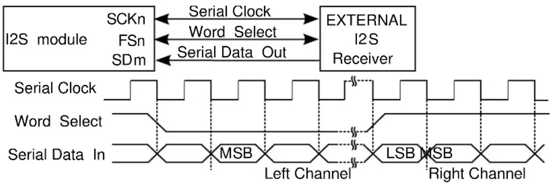
flowchart
graph LR
A["I2S module"] -->|SCKn| B["External I2S Receiver"]
A -->|FSn| B
A -->|SDm| B
B -->|Serial Clock| C["Word Select"]
B -->|Serial Data Out| D["MSB"]
C --> E["Left Channel"]
D --> F["Right Channel"]
G["Serial Clock"] --> H["Word Select"]
G --> I["Serial Data In"]
H --> J["LSB"]
I --> K["MSB"]
23.2.4.2 TDM Stream Reception/Transmission
In TDM format, the module sends several data words in each frame. For this data stream format most of the configurations could be adjusted:
- Main Frame related settings are as follow:
• Frame Sync (FS) options:
- the active edge of the FS (or if FS is inverted before use)
- the width of the FS
• the delay between FS to first data bit
• Data alignment in slot
• The number of slots and slot size can be adjusted, it has been mentioned in Audio Frame Generation
- The data word size is controlled by Serializer, it can be chosen among 8, 16, 18, 20, 24 and 32 bits.
The general TDM waveform generation is as follow:
Figure 23-3. TDM Waveform generation

text_image
Frame Sync (FSn) BIT SLOT HALF Serial Clock (SCKn) MSB LSB MSB LSB MSB LSB MSB LSB Data (SDm) Slot 0 Slot 1 Slot 2 Slot 3Some other settings could also be found to set up clock, data formatting and pin mux. refer to Clock Unit Configurations and Serializer Configurations for more details.
Following is examples for different application use cases.
See Figure 23-4: Codec Example Diagram on page 532 for the Time Slot Application connection and waveform example.
Figure 23-4. Codec Example Diagram
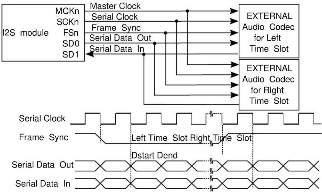
flowchart
graph TD
A["I2S module"] --> B["MCKn"]
A --> C["SCKn"]
A --> D["FSn"]
A --> E["SD0"]
A --> F["SD1"]
B --> G["Master Clock"]
C --> H["Serial Clock"]
D --> I["Frame Sync"]
E --> J["Serial Data Out"]
F --> K["Serial Data In"]
G --> L["EXTERNAL Audio Codec for Left Time Slot"]
H --> M["EXTERNAL Audio Codec for Right Time Slot"]
I --> L
J --> M
K --> M
L --> N["Serial Clock"]
M --> O["Frame Sync"]
N --> P["Left Time Slot Right Time Slot"]
O --> Q["Dstart Dend"]
P --> R["Serial Data Out"]
Q --> S["Serial Data In"]
See Figure 23-5: Time Slot Example Diagram on page 532 for the Codec Application connection and waveform example.
Figure 23-5. Time Slot Example Diagram
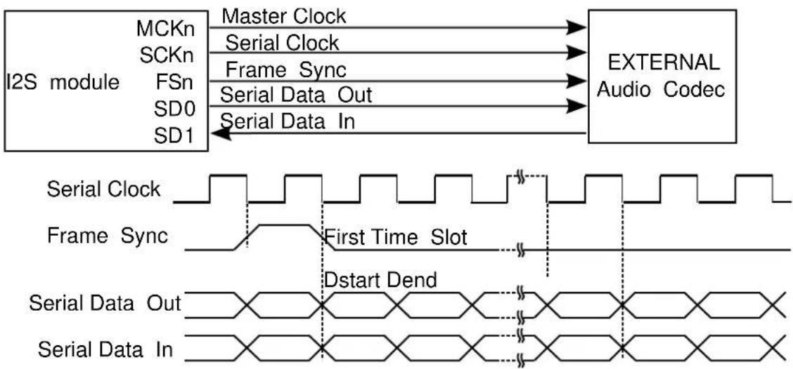
flowchart
graph LR
A["I2S module"] -->|Master Clock| B["EXTERNAL Audio Codec"]
A -->|Serial Clock| B
A -->|Frame Sync| B
A -->|Serial Data Out| B
A -->|Serial Data In| B
B --> C["Serial Clock"]
B --> D["Frame Sync"]
B --> E["Serial Data Out"]
B --> F["Serial Data In"]
C --> G["First Time Slot"]
D --> G
E --> G
F --> G
G --> H["Dstart Dend"]
23.2.4.3 PDM Reception
The I2S Serializer integrates PDM reception feature, to use this feature, simply select PDM2 mode in Serializer configuration. In PDM2 mode, it assumes two microphones are input for stereo stream. The left microphone bits will be stored in lower half and right microphone bits in upper half of the data word, like in compact stereo format.
See Figure 23-6: Time PDM2 Example Diagram on page 533 for an example of PDM Microphones Application with both left and right channel microphone connected.
Figure 23-6. Time PDM2 Example Diagram
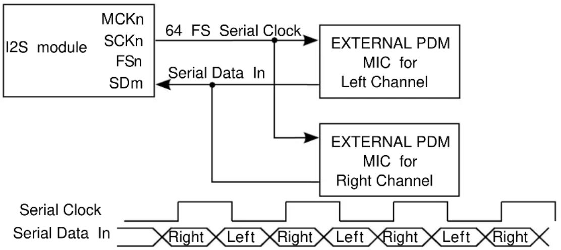
flowchart
graph TD
A["I2S module"] -->|64 FS Serial Clock| B["EXTERNAL PDM MIC for Left Channel"]
A -->|Serial Data In| C["EXTERNAL PDM MIC for Right Channel"]
B --> D["External PDM MIC for Left Channel"]
C --> E["External PDM MIC for Right Channel"]
F["Serial Clock"] --> G["Serial Data In"]
G --> H["External PDM MIC for Left Channel"]
G --> I["External PDM MIC for Right Channel"]
23.2.4.4 MONO and Compact Data
The I2S Serializer can accept some pre-defined data format and generates the data stream in specified way.
When transmitting data, the Serializer can work in MONO mode: assum input is single channel mono data on left channel and copy it to right channel automatically.
Also the I2S Serializer can support compact stereo data word. The data word size of the Serializer can be set to 16-bit compact on page 553 or 8-bit compact on page 553, with these option I2S Serializer will compact left channel data and right channel data together, the left channel data will take lower bytes and right channel data take higher bytes.
23.2.5 Loop-back Mode
The I2S can be configured to loop back the Transmitter to Receiver. In this mode Serializer's input will be connected to another Serializer's output internally.
23.2.6 Sleep Modes
The I2S will continue to operate in any sleep mode, where the selected source clocks are running.
23.3 Special Considerations
There is no special considerations for I2S module.
23.4 Extra Information
For extra information see Extra Information for I2S Driver. This includes:
- Acronyms
- Dependencies
- Errata
- Module History
23.5 Examples
For a list of examples related to this driver, see Examples for I2S Driver.
23.6 API Overview
23.6.1 Variable and Type Definitions
23.6.1.1 Type i2s_serializer_callback_t
typedef void(* i2s_serializer_callback_t )(struct i2s_module *const module)
Type of the callback functions
23.6.2 Structure Definitions
23.6.2.1 Struct i2s_clock_config
Configure for I2S clock (SCK)
Table 23-1. Members
| Type Name Description | ||
| enum gclk_generator gclk_src Clock source selection | ||
| uint8_t mck_out_div Divide generic clock to master | clock output (1~32, 0,1 means no div) | |
| bool mck_out_enable Generate MCK clock output | ||
| bool mck_out_invert Invert master clock output | ||
| enum i2s_master_clock_source mck_src Master clock source selection: | generated or input from pin | |
| uint8_t sck_div Divide generic clock to serial clock | (1~32, 0,1 means no div) | |
| bool sck_out_invert | Invert serial clock output | |
| enum i2s_serial_clock_source | sck_src | Serial clock source selection: generated or input from pin |
23.6.2.2 Struct i2s_clock_unit_config
Configure for I2S clock unit
Table 23-2. Members
| Type Name Description | ||
| struct i2s_clock_config | clock Configure clock generation | |
| struct i2s_frame_config | frame | Configure frame generation |
| struct i2s_pin_config | fs_pin | Configure frame sync pin |
| struct i2s_pin_config | mck_pin Configure master clock pin | |
| struct i2s_pin_config | sck_pin | Configure serial clock pin |
23.6.2.3 Struct i2s_frame_config
Configure fir I2S frame
Table 23-3. Members
| Type Name Description | ||
| enum i2s_data_delay data_delay Data delay from Frame Sync (FS) | to first data bit | |
| struct i2s_frame_sync_config frame_sync Frame sync (FS) | ||
| uint8_t number_slots Number of slots in a frame (1~8, | 0,1 means minimum 1) | |
| enum i2s_slot_size slot_size Size of each slot in frame | ||
23.6.2.4 Struct i2s\_frame\_sync\_config
Configure fir I2S frame sync (FS)
Table 23-4. Members
| Type Name Description | ||
| bool invert_out Invert Frame Sync (FS) signal | before output | |
| bool invert_use Invert Frame Sync (FS) signal | before use | |
| enum i2s_frame_sync_source source | Frame Sync (FS) generated or | input from pin |
| enum i2s_frame_sync_width | width | Frame Sync (FS) width |
23.6.2.5 Struct i2s\_module
Table 23-5. Members
| Type Name Description | ||
| I2s * | hw | Module HW register access base |
| struct i2s_serializer_module | serializer[] | Module Serializer used |
23.6.2.6 Struct i2s\_pin\_config
Configure for I2S pin
Table 23-6. Members
| Type Name Description | ||
| bool enable Enable this pin for I2S module | ||
| uint8_t gpio GPIO index to access the pin | ||
| uint8_t mux Pin function MUX |
23.6.2.7 Struct i2s\_serializer\_config
Configure for I2S Serializer
Table 23-7. Members
| Type Name Description | ||
| enum i2s_bit_padding | bit_padding Data Formatting Bit Extension | |
| enum i2s_clock_unit clock_unit Clock unit selection | ||
| bool data_adjust_left_in_slot Data Slot Formatting Adjust, set to | true to adjust words in slot to left | |
| bool data_adjust_left_in_word Data Word Formatting Adjust, set | to true to adjust bits in word to left | |
| enum i2s_data_padding data_padding Data padding when under-run | ||
| struct i2s_pin_config data_pin Configure Serializer data pin | ||
| enum i2s_data_size data_size Data Word Size | ||
| bool disable_data_slot[] Disable data slot | ||
| enum i2s_dma_usage dma_usage | DMA usage | |
| enum i2s_line_default_state | line_default_state | Line default state where slot is disabled |
| bool loop_back | Set to true to loop-back output to | input pin for test |
| enum i2s_serializer_mode | mode | Serializer Mode |
| bool mono_mode | Set to true to assumes mono input | and duplicate it (left channel) to right channel |
| bool transfer_lsb_first | Set to true to transfer LSB first, | false to transfer MSB first |
23.6.2.8 Struct i2s\_serializer\_module
Table 23-8. Members
| Type Name Description | ||
| i2s_serializer_callback_t | callback[] | Callbacks list for Serializer |
| enum i2s_data_size data_size Serializer data word size | ||
| uint8_t | enabled_callback_mask Callback mask for enabled callbacks | |
| void * | job_buffer Job buffer | |
| enum status_code | job_status | Status of the ongoing or last transfer job |
| enum i2s_serializer_mode | mode | Serializer mode |
| uint8_t | registered_callback_mask | Callback mask for registered callbacks |
| uint32_t | requested_words | Requested data words to read/write |
| uint32_t | transferred_words | Transferred data words for read/write |
23.6.3 Macro Definitions
23.6.3.1 Module status flags
I2S status flags, returned by i2s_get_status() and cleared by i2s_clear_status().
Macro I2S_STATUS_TRANSMIT_UNDERRUN
#define I2S_STATUS_TRANSMIT_UNDERRUN(x) \
(1u << ((x)+0))
Module Serializer x (0\~1) Transmit Underrun
Macro I2S_STATUS_TRANSMIT_READY
#define I2S_STATUS_TRANSMIT_READY(x) \
(1u << ((x)+2))
Module Serializer x (0\~1) is ready to accept new data to be transmitted
Macro I2S_STATUS_RECEIVE_OVERRUN
#define I2S_STATUS_RECEIVE_OVERRUN(x) \
(1u << ((x)+4))
Module Serializer x (0\~1) Receive Overrun
Macro I2S_STATUS_RECEIVE_READY
#define I2S_STATUS_RECEIVE_READY(x) \
(1u << ((x)+6))
Module Serializer x (0\~1) has received a new data
Macro I2S_STATUS_SYNC_BUSY
#define I2S_STATUS_SYNC_BUSY (1u << 8)
Module is busy on synchronization
23.6.4 Function Definitions
23.6.4.1 Driver Initialization
Function i2s_init()
Initializes a hardware I2S module instance.
enum status_code i2s_init(
struct i2s_module *const module_inst,
I2s * hw)
Enables the clock and initialize the I2S module.
Table 23-9. Parameters
| Data direction Parameter name Description | |
| [in, out] module_inst Pointer to the software module | instance struct |
| [in] hw Pointer to the TCC hardware | module |
Returns
Status of the initialization procedure.
Table 23-10. Return Values
| Return value Description | |
| STATUS_OK The module was initialized successfully | |
| STATUS_BUSY Hardware module was busy when the initialization procedure was attempted | |
| STATUS_ERR_DENIED Hardware module was already enabled | |
Enables a I2S module that has been previously initialized.
Table 23-11. Parameters
| Data direction Parameter name Description | |
| [in] module_inst Pointer to the software module | instance struct |
Function i2s\_disable()
Disables the I2S module.
void i2s_disable(
const struct i2s_module *const module_inst)
Disables a I2S module.
Table 23-12. Parameters
| Data direction Parameter name Description | |
| [in] module_inst Pointer to the software module | instance struct |
Function i2s\_reset()
Resets the I2S module.
void i2s_reset(
const struct i2s_module *const module_inst)
Resets the I2S module, restoring all hardware module registers to their default values and disabling the module. The I2S module will not be accessible while the reset is being performed.
Table 23-13. Parameters
| Data direction Parameter name Description | |
| [in] module_inst Pointer to the software module | instance struct |
23.6.4.3 Clock Unit Initialization and Configuration
Function i2s\_clock\_unit\_get\_config\_defaults()
Initializes config with predefined default values for I2S clock unit.
void i2s_clock_unit_get_config_defaults(
struct i2s_clock_unit_config *const config)
This function will initialize a given I2S Clock Unit configuration structure to a set of known default values. This function should be called on any new instance of the configuration structures before being modified by the user application.
The default configuration is as follow:
- The clock unit does not generate output clocks (MCK, SCK and FS)
- The pins (MCK, SCK and FS) and Mux configurations are not set
Table 23-14. Parameters
| Data direction Parameter name Description | |
| [out] config Pointer to a I2S module clock unit | configuration struct to set |
Function i2s\_clock\_unit\_set\_config()
Configure specified I2S clock unit.
enum status_code i2s_clock_unit_set_config(
struct i2s_module *const module_inst,
const enum i2s_clock_unit clock_unit,
const struct i2s_clock_unit_config * config)
Enables the clock and initialize the clock unit, based on the given configurations.
Table 23-15. Parameters
| Data direction Parameter name Description | |
| [in, out] module_inst Pointer to the software module | instance struct |
| [in] clock_unit I2S clock unit to initialize and | configure |
| [in] config Pointer to the I2S clock unit | configuration options struct |
Returns
Status of the configuration procedure.
Table 23-16. Return Values
| Return value Description | |
| STATUS_OK The module was initialized successfully | |
| STATUS_BUSY Hardware module was busy when the configuration procedure was attempted | |
| STATUS_ERR_DENIED Hardware module was already enabled | |
| STATUS_ERR_INVALID_ARG Invalid divider value or MCK direction setting conflict | |
23.6.4.4 Clock Unit Enable/Disable
Function i2s\_clock\_unit\_enable()
Enable the Specified Clock Unit of I2S module.
void i2s_clock_unit_enable(
const struct i2s_module *const module_inst,
const enum i2s_clock_unit clock_unit)
Enables a Clock Unit in I2S module that has been previously initialized.
Table 23-17. Parameters
| Data direction Parameter name Description | |
| [in] module_inst Pointer to the software module | instance struct |
| [in] clock_unit I2S Clock Unit to enable |
Function i2s\_clock\_unit\_disable()
Disable the Specified Clock Unit of I2S module.
void i2s_clock_unit_disable(
const struct i2s_module *const module_inst,
const enum i2s_clock_unit clock_unit)
Disables a Clock Unit in I2S module that has been previously initialized.
Table 23-18. Parameters
| Data direction Parameter name Description | |
| [in] module_inst Pointer to the software module | instance struct |
Data direction Parameter name Description
[in] clock_unit I2S Clock Unit to disable
23.6.4.5 Serializer Initialization and Configuration
Function i2s\_serializer\_get\_config\_defaults()
Initializes config with predefined default values for I2S Serializer.
void i2s_serializer_get_config_defaults(
struct i2s_serializer_config *const config)
This function will initialize a given I2S Clock Unit configuration structure to a set of known default values. This function should be called on any new instance of the configuration structures before being modified by the user application.
The default configuration is as follow:
• Output data does not internally loopback to input line
- Does not extend mono data (left channel) to right channel
• None of the data slot is disabled
• MSB of I2S data is transferred first
• In data word data is adjusted right
• In slot data word is adjusted left
• The data size is 16-bit width
• I2S will padd 0 to not defined bits
• I2S will padd 0 to not defined words
- I2S will use single DMA channel for all data channels
- I2S will use clock unit 0 to serve as clock
• The default data line state is 0, when there is no data
• I2S will transmit data to output line
• The data pin and Mux configuration are not set
Table 23-19. Parameters
| Data direction Parameter name Description | |
| [out] config Pointer to a I2S module Serializer | configuration struct to set |
Function i2s\_serializer\_set\_config()
Configure specified I2S serializer.
enum status_code i2s_serializer_set_config(
struct i2s_module *const module_inst,
const enum i2s_serializer serializer,
const struct i2s_serializer_config * config)
Enables the clock and initialize the serializer, based on the given configurations.
Table 23-20. Parameters
| Data direction Parameter name Description | |
| [in, out] module_inst Pointer to the software module | instance struct |
| [in] serializer I2S serializer to initialize and | configure |
| [in] config Pointer to the I2S serializer | configuration options struct |
Returns
Status of the configuration procedure.
Table 23-21. Return Values
| Return value Description | |
| STATUS_OK The module was initialized successfully | |
| STATUS_BUSY Hardware module was busy when the configuration procedure was attempted | |
| STATUS_ERR_DENIED Hardware module was already enabled | |
23.6.4.6 Serializer Enable/Disable
Function i2s\_serializer\_enable()
Enable the Specified Serializer of I2S module.
void i2s_serializer_enable(
const struct i2s_module *const module_inst,
const enum i2s_serializer serializer)
Enables a Serializer in I2S module that has been previously initialized.
Table 23-22. Parameters
| Data direction Parameter name Description | |
| [in] module_inst Pointer to the software module | instance struct |
| [in] serializer I2S Serializer to enable |
Function i2s\_serializer\_disable()
Disable the Specified Serializer of I2S module.
void i2s_serializer_disable(
const struct i2s_module *const module_inst,
const enum i2s_serializer serializer)
Disables a Serializer in I2S module that has been previously initialized.
Table 23-23. Parameters
| Data direction Parameter name Description | |
| [in] module_inst Pointer to the software module | instance struct |
| [in] serializer I2S Serializer to disable |
23.6.4.7 Status Management
Function i2s\_get\_status()
Retrieves the current module status.
uint32_t i2s_get_status(
const struct i2s_module *const module_inst)
Retrieves the status of the module, giving overall state information.
Table 23-24. Parameters
| Data direction Parameter name Description | |
| [in] module_inst Pointer to the I2S software | instance struct |
Returns
Bitmask of I2S_STATUS_* flags
Table 23-25. Return Values
| Return value Description | |
| I2S_STATUS_SYNC_BUSY Module is busy synchronization | |
| I2S_STATUS_TRANSMIT_UNDERRUN(x) Serializer x (0~1) is underrun | |
| I2S_STATUS_TRANSMIT_READY(x) Serializer x (0~1) is ready to transmit new data word | |
| I2S_STATUS_RECEIVE_OVERRUN(x) Serializer x (0~1) is overrun | |
| I2S_STATUS_RECEIVE_READY(x) Serializer x (0~1) has data ready to read | |
Function i2s\_clear\_status()
Clears a module status flags.
void i2s_clear_status(
const struct i2s_module *const module_inst,
uint32_t status)
Clears the given status flags of the module.
Table 23-26. Parameters
| Data direction Parameter name Description | |
| [in] module_inst Pointer to the I2S software | instance struct |
| [in] status | Bitmask of I2S_STATUS_* flags to clear |
Function i2s\_enable\_status\_interrupt()
Enable interrupts on status set.
enum status_code i2s_enable_status_interrupt(
struct i2s_module *const module_inst,
uint32_t status)
Enable the given status interrupt request from the I2S module.
Table 23-27. Parameters
| Data direction Parameter name Description | |
| [in] module_inst Pointer to the I2S software | instance struct |
| [in] status Status interrupts to enable |
Returns
Status of enable procedure
Table 23-28. Return Values
| Return value Description | |
| STATUS_OK Interrupt is enabled successfully | |
| STATUS_ERR_INVALID_ARG Status with no interrupt is passed | |
Function i2s\_disable\_status\_interrupt()
Disable interrupts on status set.
void i2s_disable_status_interrupt(
struct i2s_module *const module_inst,
uint32_t status)
Disable the given status interrupt request from the I2S module.
Table 23-29. Parameters
| Data direction Parameter name Description | |
| [in] module_inst Pointer to the I2S software | instance struct |
| [in] status Status interrupts to disable |
23.6.4.8 Data read/write
Function i2s\_serializer\_write\_wait()
Write a data word to the specified Serializer of I2S module.
void i2s_serializer_write_wait(
const struct i2s_module *const module_inst,
enum i2s_serializer serializer,
uint32_t data)
Table 23-30. Parameters
| Data direction Parameter name Description | |
| [in] module_inst Pointer to the software module | instance struct |
| [in] serializer The Serializer to write to | |
| [in] data The data to write |
Function i2s\_serializer\_read\_wait()
Read a data word from the specified Serializer of I2S module.
uint32_t i2s_serializer_read_wait( const struct i2s_module *const module_inst, enum i2s_serializer serializer)
Table 23-31. Parameters
| Data direction Parameter name Description | |
| [in] module_inst Pointer to the software module | instance struct |
| [in] serializer The Serializer to read |
Function i2s\_serializer\_write\_buffer\_wait()
Write buffer to the specified Serializer of I2S module.
enum status_code i2s_serializer_write_buffer_wait( const struct i2s_module *const module_inst, enum i2s_serializer serializer, void * buffer, uint32_t size)
Table 23-32. Parameters
| Data direction Parameter name Description | |
| [in] module_inst Pointer to the software module | instance struct |
| [in] serializer The Serializer to write to | |
| [in] buffer The data buffer to write | |
| [in] size Number of data words to write |
Returns
Status of the initialization procedure.
Table 23-33. Return Values
| Return value Description | |
| STATUS_OK The data was sent successfully | |
| STATUS_INVALID_ARG An invalid buffer pointer was supplied | |
Table 23-34. Parameters
| Data direction Parameter name Description | |
| [in] module_inst Pointer to the software module | instance struct |
| [in] serializer The serializer to write to | |
| [in] buffer The data buffer to write | |
| [in] size Number of data words to write |
Returns
Status of the initialization procedure.
Table 23-35. Return Values
| Return value Description | |
| STATUS_OK The data was sent successfully | |
| STATUS_ERR_DENIED The module or serializer is disabled | |
| STATUS_ERR_INVALID_ARG An invalid buffer pointer was supplied |
Function i2s\_serializer\_read\_buffer\_wait()
Read from the specified Serializer of I2S module to a buffer.
enum status_code i2s_serializer_read_buffer_wait( const struct i2s_module *const module_inst, enum i2s_serializer serializer, void * buffer, uint32_t size)
Table 23-36. Parameters
| Data direction Parameter name Description | |
| [in] module_inst Pointer to the software module | instance struct |
| [in] serializer The Serializer to write to | |
| [in] buffer The buffer to fill read data | |
| [in] size Number of data words to read |
Returns
Status of the initialization procedure.
Table 23-37. Return Values
| Return value Description | |
| STATUS_OK The data was sent successfully | |
| STATUS_INVALID_ARG An invalid buffer pointer was supplied | |
Table 23-38. Parameters
| Data direction Parameter name Description | |
| [in] module_inst Pointer to the software module | instance struct |
| [in] serializer The serializer to write to | |
| [in] buffer The buffer to fill read data (NULL to discard) | |
| [in] size Number of data words to read |
Returns
Status of the initialization procedure.
Table 23-39. Return Values
| Return value Description | |
| STATUS_OK The data was sent successfully | |
| STATUS_ERR_DENIED The module or serializer is disabled | |
| STATUS_ERR_INVALID_ARG An invalid buffer pointer was supplied | |
23.6.4.9 Callback Management
Function i2s\_serializer\_register\_callback()
Registers a callback for serializer.
void i2s_serializer_register_callback(
struct i2s_module *const module_inst,
const enum i2s_serializer serializer,
const i2s_serializer_callback_t callback_func,
const enum i2s_serializer_callback callback_type)
Registers a callback function which is implemented by the user.
Note
The callback must be enabled by for the interrupt handler to call it when the condition for the callback is met.
Table 23-40. Parameters
| Data direction Parameter name Description | |
| [in] module Pointer to ADC software instance | struct |
| [in] serializer The serializer that generates | callback |
| [in] callback_func Pointer to callback function | |
| [in] callback_type Callback type given by an enum |
Function i2s\_serializer\_unregister\_callback()
Unregisters a callback for serializer.
void i2s_serializer_unregister_callback(struct i2s_module *const module_inst, const enum i2s_serializer serializer,
const enum i2s_serializer_callback callback_type)
Unregisters a callback function which is implemented by the user.
Table 23-41. Parameters
| Data direction Parameter name Description | |
| [in] module Pointer to ADC software instance | struct |
| [in] serializer The serializer that generates | callback |
| [in] callback_type Callback type given by an enum |
Function i2s\_serializer\_enable\_callback()
Enables callback for serializer.
void i2s_serializer_enable_callback(
struct i2s_module *const module_inst,
const enum i2s_serializer serializer,
const enum i2s_serializer_callback callback_type)
Enables the callback function registered by i2s_serializer_register_callback. The callback function will be called from the interrupt handler when the conditions for the callback type are met.
Table 23-42. Parameters
| Data direction Parameter name Description | |
| [in] module Pointer to ADC software instance | struct |
| [in] serializer The serializer that generates | callback |
| [in] callback_type Callback type given by an enum |
Function i2s\_serializer\_disable\_callback()
Disables callback for Serializer.
void i2s_serializer_disable_callback(
struct i2s_module *const module_inst,
const enum i2s_serializer serializer,
const enum i2s_serializer_callback callback_type)
Disables the callback function registered by the i2s_serializer_register_callback.
Table 23-43. Parameters
| Data direction Parameter name Description | |
| [in] module Pointer to ADC software instance | struct |
| [in] serializer The serializer that generates | callback |
| [in] callback_type Callback type given by an enum |
23.6.4.10 Job Management
Function i2s\_serializer\_write\_buffer\_job()
Write buffer to the specified Serializer of I2S module.
enum status_code i2s_serializer_write_buffer_job(
struct i2s_module *const module_inst,
const enum i2s_serializer serializer,
const void * buffer,
const uint32_t size)
Table 23-44. Parameters
| Data direction Parameter name Description | |
| [in] module_inst Pointer to the software module | instance struct |
| [in] serializer The serializer to write to | |
| [in] buffer The data buffer to write | |
| [in] size Number of data words to write |
Returns
Status of the initialization procedure.
Table 23-45. Return Values
| Return value Description | |
| STATUS_OK The data was sent successfully | |
| STATUS_ERR_DENIED The serializer is not in transmit mode | |
| STATUS_ERR_INVALID_ARG An invalid buffer pointer was supplied |
Function i2s\_serializer\_read\_buffer\_job()
Read from the specified Serializer of I2S module to a buffer.
enum status_code i2s_serializer_read_buffer_job(
struct i2s_module *const module_inst,
const enum i2s_serializer serializer,
void * buffer,
const uint32_t size)
Table 23-46. Parameters
| Data direction Parameter name Description | |
| [in] module_inst Pointer to the software module | instance struct |
| [in] serializer The serializer to write to | |
| [out] buffer The buffer to fill read data | |
| [in] size Number of data words to read |
Returns
Status of the initialization procedure.
Table 23-47. Return Values
| Return value Description | |
| STATUS_OK The data was sent successfully | |
| STATUS_ERR_DENIED The serializer is not in receive mode | |
| STATUS_ERR_INVALID_ARG An invalid buffer pointer was supplied | |
Function i2s\_serializer\_abort\_job()
Aborts an ongoing job running on serializer.
void i2s_serializer_abort_job(
struct i2s_module *const module_inst,
const enum i2s_serializer serializer,
const enum i2s_job_type job_type)
Aborts an ongoing job.
Table 23-48. Parameters
| Data direction Parameter name Description | |
| [in] module_inst Pointer to the software module | instance struct |
| [in] serializer The serializer which runs the job | |
| [in] job_type Type of job to abort |
Function i2s\_serializer\_get\_job\_status()
Gets the status of a job running on serializer.
enum status_code i2s_serializer_get_job_status( const struct i2s_module *const module_inst, const enum i2s_serializer serializer, const enum i2s_job_type job_type)
Gets the status of an ongoing or the last job.
Table 23-49. Parameters
| Data direction Parameter name Description | |
| [in] module_inst Pointer to the software module | instance struct |
| [in] serializer The serializer which runs the job | |
| [in] job_type Type of job to abort |
Returns
Status of the job
23.6.4.11 Function i2s\_is\_syncing()
Determines if the hardware module(s) are currently synchronizing to the bus.
bool i2s_is_syncing(
const struct i2s_module *const module_inst)
Checks to see if the underlying hardware peripheral module(s) are currently synchronizing across multiple clock domains to the hardware bus. This function can be used to delay further operations on a module until such time that it is ready, to prevent blocking delays for synchronization in the user application.
Table 23-50. Parameters
| Data direction Parameter name Description | |
| [in] module_inst Pointer to the software module | instance struct |
Returns
Synchronization status of the underlying hardware module(s).
Table 23-51. Return Values
| Return value Description | |
| true if the module has completed synchronization | |
| false if the module synchronization is ongoing |
23.6.5 Enumeration Definitions
23.6.5.1 Enum i2s\_bit\_order
I2S data bit order
Table 23-52. Members
| Enum value Description | |
| I2S_BIT_ORDER_MSB_FIRST Transfer Data Most Significant | Bit first (Default for I2S protocol) |
| I2S_BIT_ORDER_LSB_FIRST Transfer Data Least Significant | Bit first |
23.6.5.2 Enum i2s\_bit\_padding
I2S data bit padding
Table 23-53. Members
| Enum value Description | |
| I2S_BIT_PADDING_0 Padding with 0 | |
| I2S_BIT_PADDING_1 Padding with 1 | |
| I2S_BIT_PADDING_MSB | Padding with MSBit |
| I2S_BIT_PADDING_LSB | Padding with LSBit |
23.6.5.3 Enum i2s\_clock\_unit
I2S clock unit selection
Table 23-54. Members
| Enum value Description | |
| I2S_CLOCK_UNIT_0 Clock Unit channel 0 | |
| I2S_CLOCK_UNIT_1 Clock Unit channel 1 | |
| I2S_CLOCK_UNIT_N Number of Clock Unit channels |
23.6.5.4 Enum i2s\_data\_adjust
I2S data word adjust
Table 23-55. Members
| Enum value Description | |
| I2S_DATA_ADJUST_RIGHT Data is right adjusted in word | |
| I2S_DATA_ADJUST_LEFT Data is left adjusted in word |
23.6.5.5 Enum i2s\_data\_delay
Data delay from Frame Sync (FS)
Table 23-56. Members
| Enum value Description | |
| I2S_DATA_DELAY_0 Left Justified (no delay) | |
| I2S_DATA_DELAY_1 I2S data delay (1-bit delay) | |
| I2S_DATA_DELAY_LEFT_JUSTIFIED Left Justified (no delay) | |
| I2S_DATA_DELAY_I2S I2S data delay (1-bit delay) |
23.6.5.6 Enum i2s\_data\_format
I2S data format, to extend mono data to 2 channels
Table 23-57. Members
| Enum value Description | |
| I2S_DATA_FORMAT_STEREO Normal mode, keep data to its right channel | |
| I2S_DATA_FORMAT_MONO Assume input is mono data for left channel, the data is duplicated to right channel | |
23.6.5.7 Enum i2s\_data\_padding
I2S data padding
Table 23-58. Members
| Enum value Description | |
| I2S_DATA_PADDING_0 Padding 0 in case of under-run | |
| I2S_DATA_PADDING_SAME_AS_LAST Padding last data in case of under-run | |
| I2S_DATA_PADDING_LAST Padding last data in case of under-run (abbr.I2S_DATA_PADDING_SAME_AS_LAST) | |
Enum value Description
I2S_DATA_PADDING_SAME Padding last data in case of under-run (abbr.
I2S_DATA_PADDING_SAME_AS_LAST)
23.6.5.8 Enum i2s\_data\_size
I2S data word size
Table 23-59. Members
| Enum value Description | |
| I2S_DATA_SIZE_32BIT 32-bit | |
| I2S_DATA_SIZE_24BIT 24-bit | |
| I2S_DATA_SIZE_20BIT 20-bit | |
| I2S_DATA_SIZE_18BIT 18-bit | |
| I2S_DATA_SIZE_16BIT 16-bit | |
| I2S_DATA_SIZE_16BIT_COMPACT 16-bit compact stereo | |
| I2S_DATA_SIZE_8BIT 8-bit | |
| I2S_DATA_SIZE_8BIT_COMPACT 8-bit compact stereo |
23.6.5.9 Enum i2s\_dma\_usage
DMA channels usage for I2S
Table 23-60. Members
| Enum value Description | |
| I2S_DMA_USE_SINGLE_CHANNEL_FOR_ALL Single DMA channel for all I2S channels | |
| I2S_DMA_USE_ONE_CHANNEL_PER_DATA_CHANNEL One DMA channel per data channel | |
23.6.5.10 Enum i2s\_frame\_sync\_source
Frame Sync (FS) source
Table 23-61. Members
| Enum value Description | |
| I2S_FRAME_SYNC_SOURCE_SCKDIV Frame Sync (FS) is divided from I2S Serial Clock | |
| I2S_FRAME_SYNC_SOURCE_FSPIN Frame Sync (FS) is input from FS input pin | |
23.6.5.11 Enum i2s\_frame\_sync\_width
Frame Sync (FS) output pulse width
Table 23-62. Members
| Enum value Description | |
| I2S_FRAME_SYNC_WIDTH_SLOT Frame Sync (FS) Pulse is 1 Slot width | |
| I2S_FRAME_SYNC_WIDTH_HALF_FRAME Frame Sync (FS) Pulse is half a Frame width | |
| I2S_FRAME_SYNC_WIDTH_BIT | Frame Sync (FS) Pulse is 1 Bit width |
| I2S_FRAME_SYNC_WIDTH_BURST 1-bit wide Frame Sync (FS) per Data sample, only used when Data transfer is requested | |
23.6.5.12 Enum i2s\_job\_type
Enum for the possible types of I2S asynchronous jobs that may be issued to the driver.
Table 23-63. Members
| Enum value Description | |
| I2S_JOB_WRITE_BUFFER Asynchronous I2S write from a user provided buffer | |
| I2S_JOB_READ_BUFFER Asynchronous I2S read into a user provided buffer | |
23.6.5.13 Enum i2s\_line\_default\_state
I2S line default value when slot disabled
Table 23-64. Members
| Enum value Description | |
| I2S_LINE_DEFAULT_0 Output default value is 0 | |
| I2S_LINE_DEFAULT_1 Output default value is 1 | |
| I2S_LINE_DEFAULT_HIGH_IMPEDANCE Output default value is high impedance | |
| I2S_LINE_DEFAULT_HIZ Output default value is high impedance (abbr. I2S_LINE_DEFAULT_HIGH_IMPEDANCE) | |
23.6.5.14 Enum i2s\_master\_clock\_source
Master Clock (MCK) source selection
Table 23-65. Members
| Enum value Description | |
| I2S_MASTER_CLOCK_SOURCE_GCLK Master Clock (MCK) is from general clock | |
| I2S_MASTER_CLOCK_SOURCE_MCKPIN Master Clock (MCK) is from MCK input pin | |
23.6.5.15 Enum i2s\_serial\_clock\_source
Serial Clock (SCK) source selection
Table 23-66. Members
| Enum value Description | |
| I2S_SERIAL_CLOCK_SOURCE_MCKDIV Serial Clock (SCK) is divided from Master Clock | |
| I2S_SERIAL_CLOCK_SOURCE_SCKPIN Serial Clock (SCK) is input from SCK input pin | |
23.6.5.16 Enum i2s\_serializer
I2S Serializer selection
Table 23-67. Members
| Enum value Description | |
| I2S_SERIALIZER_0 Serializer channel 0 | |
| I2S_SERIALIZER_1 Serializer channel 1 | |
| I2S_SERIALIZER_N Number of Serializer channels |
23.6.5.17 Enum i2s\_serializer\_callback
Table 23-68. Members
| Enum value Description | |
| I2S_SERIALIZER_CALLBACK_BUFFER_DONE | Callback for buffer read/write finished |
| I2S_SERIALIZER_CALLBACK_OVER_UNDER_RUN | Callback for Serializer overrun/underrun |
23.6.5.18 Enum i2s\_serializer\_mode
I2S Serializer mode
Table 23-69. Members
| Enum value Description | |
| I2S_SERIALIZER_RECEIVE Serializer is used to receive data | |
| I2S_SERIALIZER_TRANSMIT Serializer is used to transmit data | |
| I2S_SERIALIZER_PDM2 Serializer is used to receive PDM data on each clock edge |
23.6.5.19 Enum i2s\_slot\_adjust
I2S data slot adjust
Table 23-70. Members
| Enum value Description | |
| I2S_SLOT_ADJUST_RIGHT Data is right adjusted in slot | |
| I2S_SLOT_ADJUST_LEFT Data is left adjusted in slot |
23.6.5.20 Enum i2s\_slot\_size
Time Slot Size in number of I2S serial clocks (bits)
Table 23-71. Members
| Enum value Description | |
| I2S_SLOT_SIZE_8_BIT 8-bit slot | |
| I2S_SLOT_SIZE_16_BIT 16-bit slot | |
| I2S_SLOT_SIZE_24_BIT 24-bit slot | |
| I2S_SLOT_SIZE_32_BIT 32-bit slot |
23.7 Extra Information for I2S Driver
23.7.1 Acronyms
Below is a table listing the acronyms used in this module, along with their intended meanings.
| Acronym Description | |
| I2S, IIS Inter-IC Sound Controller | |
| MCK Master Clock | |
| SCK Serial Clock | |
| FS Frame Sync | |
| SD Serial Data | |
| ADC Analog-to-Digital Converter | |
| DAC Digital-to-Analog Converter | |
| TDM Time Division Multiplexed | |
| PDM Pulse Density Modulation | |
| LSB Least Significant Bit | |
| MSB Most Significant Bit | |
| DSP Digital Signal Processor |
23.7.2 Dependencies
This driver has the following dependencies:
• System Pin Multiplexer Driver
23.7.3 Errata
There are no errata related to this driver.
23.7.4 Module History
An overview of the module history is presented in the table below, with details on the enhancements and fixes made to the module since its first release. The current version of this corresponds to the newest version in the table.
Changelog
Initial Release
23.8 Examples for I2S Driver
This is a list of the available Quick Start guides (QSGs) and example applications for SAM D21 Inter-IC Sound Controller Driver (I2S). QSGs are simple examples with step-by-step instructions to configure and use this driver in a selection of use cases. Note that QSGs can be compiled as a standalone application or be added to the user application.
- Quick Start Guide for I2S - Basic
- Quick Start Guide for I2S - Callback
- Quick Start Guide for I2S - DMA
23.8.1 Quick Start Guide for I2S - Basic
In this use case, the I2S will be used to generate Master Clock (MCK), Serial Clock (SCK), Frame Sync (FS) and Serial Data (SD) signals.
Here MCK is set to the half of processor clock. SCK is set to a quarter of the frequency of processor. FS generates half-half square wave for left and right audio channel data. The output serial data of channels toggle from two values to generate square wave, if codec or DAC is connected.
The I2S module will be set up as follows:
• GCLK generator 0 (GCLK main) clock source
• MCK, SCK and FS clocks outputs are enabled
• MCK output divider set to 2
• SCK generation divider set to 4
• Each frame will contain 2 32-bit slots
• Data will be left adjusted and start transmit without delay
23.8.1.1 Quick Start
Prerequisites
There are no prerequisites for this use case.
Code
Add to the main application source file, before any functions:
#define CONF_I2S_MODULE I2S
#define CONF_I2S_MCK_PIN PIN_PA09G_I2S_MCK0
#define CONF_I2S_MCK_MUX MUX_PA09G_I2S_MCK0
#define CONF_I2S_SCK_PIN PIN_PA10G_I2S_SCK0
#define CONF_I2S_SCK_MUX MUX_PA10G_I2S_SCK0
#define CONF_I2S_FS_PIN PIN_PA11G_I2S_FS0
#define CONF_I2S_FS_MUX MUX_PA11G_I2S_FS0
#define CONF_I2S_SD_PIN PIN_PA07G_I2S_SD0
#define CONF_I2S_SD_MUX MUX_PA07G_I2S_SD0
Add to the main application source file, outside of any functions:
struct i2s_module i2s_instance;
Copy-paste the following setup code to your user application:
static void _configure_i2s(void)
{
i2s_init(&i2s_instance, CONF_I2S_MODULE);
struct i2s_clock_unit_config config_clock_unit;
i2s_clock_unit_get_config_defaults(&config_clock_unit);
config_clock_unit.clock.gclk_src = GCLK_GENERATOR_0;
config_clock_unit.clock.mck_src = I2S_MASTER_CLOCK_SOURCE_GCLK;
config_clock_unit.clock.mck_out_enable = true;
config_clock_unit.clock.mck_out_div = 2;
config_clock_unit.clock.sck_src = I2S_SERIAL_CLOCK_SOURCE_MCKDIV;
config_clock_unit.clock.sck_div = 4;
config_clock_unit.frame.number_slots = 2;
config_clock_unit.frame.slot_size = I2S_SLOT_SIZE_32_BIT;
config_clock_unit.frame.data_delay = I2S_DATA_DELAY_0;
config_clock_unit.frame.frame_sync.source = I2S_FRAME_SYNC_SOURCE_SCKDIV;
config_clock_unit.frame.frame_sync.width = I2S_FRAME_SYNC_WIDTH_HALF_FRAME;
config_clock_unit.mck_pin.enable = true;
config_clock_unit.mck_pinISCO = CONF_I2S_MCK_PIN;
config_clock_unit.mck_pin.mux = CONF_I2S_MCK_MUX;
config_clock_unit.sck_pin.enable = true;
config_clock_unit.sck_pinISCO = CONF_I2S_SCK_PIN;
config_clock_unit.sck_pin.mux = CONF_I2S_SCK_MUX;
config_clock_unit.fs_pin.enable = true;
config_clock_unit.fs_pinISCO = CONF_I2S_FS_PIN;
config_clock_unit.fs_pin.mux = CONF_I2S_FS_MUX;
i2s_clock_unit_set_config(&i2s_instance, I2S_CLOCK_UNIT_0, &config_clock_unit);
struct i2s_serializer_config_config_serializer;
i2s tedalizer_get_config_defaults(&config tedalizer);
config tedalizer.clock_unit = I2S_CLOCK_UNIT_0;
config tedalizer.mode = I2S_SERIALIZER_TRANSMIT;
config tedalizer.data_size = I2S_DATA_SIZE_16BIT;
config tedalizer.data_pin.enable = true;
config tedalizer.data_pinISCO = CONF_I2S_SD_PIN;
config tedalizer.data_pin.mux = CONF_I2S_SD_MUX;
i2s tedalizer_set_config(&i2s_instance, I2S_SERIALIZER_0, &config tedalizer);
i2s_enable(&i2s_instance);
i2s_clock_unit_enable(&i2s_instance, I2S_CLOCK_UNIT_0);
i2s tedalizer_enable(&i2s_instance, I2S_SERIALIZER_0);
}
Add to user application initialization (typically the start of main()):
_configure_i2s();
Workflow
- Create a module software instance structure for the I2S module to store the I2S driver state while it is in use.
struct i2s_module i2s_instance;
Note
This should never go out of scope as long as the module is in use. In most cases, this should be global.
- Configure the I2S module.
a. Initialize the I2S module.
i2s_init(&i2s_instance, CONF_I2S_MODULE);
b. Initialize the I2S Clock Unit.
i. Create a I2S Clock Unit configuration struct, which can be filled out to adjust the configuration of a physical I2S Clock Unit.
struct i2s_clock_unit_config config_clock_unit;
ii. Initialize the I2S Clock Unit configuration struct with the module's default values.
i2s_clock_unit_get_config_defaults(&config_clock_unit);
Note
This should always be performed before using the configuration struct to ensure that all values are initialized to known default settings.
iii. Alter the I2S Clock Unit settings to configure the general clock source, MCK, SCK and FS generation.
config_clock_unit.clock.gclk_src = GCLK_GENERATOR_0;
config_clock_unit.clock.mck_src = I2S_MASTER_CLOCK_SOURCE_GCLK;
config_clock_unit.clock.mck_out_enable = true;
config_clock_unit.clock.mck_out_div = 2;
config_clock_unit.clock.sck_src = I2S_SERIAL_CLOCK_SOURCE_MCKDIV;
config_clock_unit.clock.sck_div = 4;
config_clock_unit.frame.number_slots = 2;
config_clock_unit.frame.slot_size = I2S_SLOT_SIZE_32_BIT;
config_clock_unit.frame.data_delay = I2S_DATA_DELAY_0;
config_clock_unit.frame.frame_sync.source = I2S_FRAME_SYNC_SOURCE_SCKDIV;
config_clock_unit.frame.frame_sync.width = I2S_FRAME_SYNC_WIDTH_HALF_FRAME;
iv. Alter the I2S Clock Unit settings to configure the MCK, SCK and FS output on physical device pins.
config_clock_unit.mck_pin.enable = true;
config_clock_unit.mck_pinISCO = CONF_I2S_MCK_PIN;
config_clock_unit.mck_pin.mux = CONF_I2S_MCK_MUX;
config_clock_unit.sck_pin.enable = true;
config_clock_unit.sck_pinISCO = CONF_I2S_SCK_PIN;
config_clock_unit.sck_pin.mux = CONF_I2S_SCK_MUX;
config_clock_unit.fs_pin.enable = true;
config_clock_unit.fs_pinISCO = CONF_I2S_FS_PIN;
config_clock_unit.fs_pin.mux = CONF_I2S_FS_MUX;
v. Configure the I2S Clock Unit with the desired settings.
i2s_clock_unit_set_config(&i2s_instance, I2S_CLOCK_UNIT_0, &config_clock_unit);
c. Initialize the I2S Serializer.
i. Create a I2S Serializer configuration struct, which can be filled out to adjust the configuration of a physical I2S Serializer.
struct i2s_serializer_config config_serializer;
ii. Initialize the I2S Serializer configuration struct with the module's default values.
i2s_serializer_get_config_defaults(&config_serializer);
Note
This should always be performed before using the configuration struct to ensure that all values are initialized to known default settings.
iii. Alter the I2S Serializer settings to configure the serial data generation.
config_serializer.clock_unit = I2S_CLOCK_UNIT_0;
config_serial.mode = I2S_SERIALIZER_TRANSMIT;
config_serial.data_size = I2S_DATA_SIZE_16BIT;
iv. Alter the I2S Serializer settings to configure the SD on a physical device pin.
config_serializer.data_pin.enable = true;
config_serializer.data_pinISCO = CONF_I2S_SD_PIN;
config_serializer.data_pin.mux = CONF_I2S_SD_MUX;
v. Configure the I2S Serializer with the desired settings.
i2s_serializer_set_config(&i2s_instance, I2S_SERIALIZER_0, &config_serializer);
d. Enable the I2S module, the Clock Unit and Serializer to start the clocks and ready to transmit data.
i2s_enable(&i2s_instance);
i2s_clock_unit_enable(&i2s_instance, I2S_CLOCK_UNIT_0);
i2s_serializer_enable(&i2s_instance, I2S_SERIALIZER_0);
23.8.1.2 Use Case
Code
Copy-paste the following code to your user application:
while (true) {
/* Infinite loop */
Atmel
i2s_serializer_write_wait(&i2s_instance, I2S_SERIALIZER_0, 0xF87F);
i2s_serializer_write_wait(&i2s_instance, I2S_SERIALIZER_0, 0x901F);
i2s_serializer_write_wait(&i2s_instance, I2S_SERIALIZER_0, 0);
i2s_serializer_write_wait(&i2s_instance, I2S_SERIALIZER_0, 0);
Workflow
- Enter an infinite loop to output data sequence via the I2S Serializer.
while (true) {
/* Infinite loop */
i2s_serializer_write_wait(&i2s_instance, I2S_SERIALIZER_0, 0xF87F);
i2s_serializer_write_wait(&i2s_instance, I2S_SERIALIZER_0, 0x901F);
i2s_serializer_write_wait(&i2s_instance, I2S_SERIALIZER_0, 0);
i2s tedalizer_write_wait(&i2s_instance, I2S_SERIALIZER_0, 0);
}
23.8.2 Quick Start Guide for I2S - Callback
In this use case, the I2S will be used to generate Master Clock (MCK), Serial Clock (SCK), Frame Sync (FS) and Serial Data (SD) signals.
Here MCK is set to the half of processor clock. SCK is set to a quarter of the frequency of processor. FS generates half-half square wave for left and right audio channel data. The output serial data of channels toggle from two values to generate square wave, if codec or DAC is connected.
The I2S module will be set up as follows:
• GCLK generator 0 (GCLK main) clock source
• MCK, SCK and FS clocks outputs are enabled
• MCK output divider set to 2
• SCK generation divider set to 4
• Each frame will contain 2 32-bit slots
• Data will be left adjusted and start transmit without delay
23.8.2.1 Quick Start
Prerequisites
There are no prerequisites for this use case.
Code
Add to the main application source file, before any functions:
#define CONF_I2S_MODULE I2S
#define CONF_I2S_MCK_PIN PIN_PA09G_I2S_MCK0
#define CONF_I2S_MCK_MUX MUX_PA09G_I2S_MCK0
#define CONF_I2S_SCK_PIN PIN_PA10G_I2S_SCK0
#define CONF_I2S_SCK_MUX MUX_PA10G_I2S_SCK0
#define CONF_I2S_FS_PIN PIN_PA11G_I2S_FS0
#define CONF_I2S_FS_MUX MUX_PA11G_I2S_FS0
#define CONF_I2S_SD_PIN PIN_PA07G_I2S_SD0
#define CONF_I2S_SD_MUX MUX_PA07G_I2S_SD0
Add to the main application source file, outside of any functions:
struct i2s_module i2s_instance;
Copy-paste the following data buffer code to your user application:
uint16_t data_buffer[4] = {0xF87F, 0x901F, 0, 0};
Copy-paste the following callback function code to your user application:
static void _i2s_callback_to_send_buffer(
struct i2s_module *const module_inst)
{
i2s_serializer_write_buffer_job(module_inst,
I2S_SERIALIZER_0, data_buffer, 4);
}
Copy-paste the following setup code to your user application:
static void _configure_i2s(void)
{
i2s_init(&i2s_instance, CONF_I2S_MODULE);
struct i2s_clock_unit_config config_clock_unit;
i2s_clock_unit_get_config_defaults(&config_clock_unit);
config_clock_unit.clock.gclk_src = GCLK_GENERATOR_0;
config_clock_unit.clock.mck_src = I2S_MASTER_CLOCK_SOURCE_GCLK;
config_clock_unit.clock.mck_out_enable = true;
config_clock_unit.clock.mck_out_div = 2;
config_clock_unit.clock.sck_src = I2S_SERIAL_CLOCK_SOURCE_MCKDIV;
config_clock_unit.clock.sck_div = 4;
config_clock_unit.frame.number_slots = 2;
config_clock_unit.frame.slot_size = I2S_SLOT_SIZE_32_BIT;
config_clock_unit.frame.data_delay = I2S_DATA_DELAY_0;
config_clock_unit.frame.frame_sync.source = I2S_FRAME_SYNC_SOURCE_SCKDIV;
config_clock_unit.frame.frame_sync.width = I2S_FRAME_SYNC_WIDTH_HALF_FRAME;
config_clock_unit.mck_pin.enable = true;
config_clock_unit.mck_pinISCO = CONF_I2S_MCK_PIN;
config_clock_unit.mck_pin.mux = CONF_I2S_MCK_MUX;
config_clock_unit.sck_pin.enable = true;
config_clock_unit.sck_pinISCO = CONF_I2S_SCK_PIN;
config_clock_unit.sck_pin.mux = CONF_I2S_SCK_MUX;
config_clock_unit.fs_pin.enable = true;
config_clock_unit.fs_pinISCO = CONF_I2S_FS_PIN;
config_clock_unit.fs_pin.mux = CONF_I2S_FS_MUX;
i2s_clock_unit_set_config(&i2s_instance, I2S_CLOCK_UNIT_0, &config_clock_unit);
struct i2s_serializer_config_config_serializer;
i2s_serializer_get_config_defaults(&config_serializer);
config_serializer.clock_unit = I2S_CLOCK_UNIT_0;
config_serializer.mode = I2S_SERIALIZER_TRANSMIT;
config_serializer.data_size = I2S_DATA_SIZE_16BIT;
config tedalizer.data_pin.enable = true;
config tedalizer.data_pinISCO = CONF_I2S_SD_PIN;
config tedalizer.data_pin.mux = CONF_I2S_SD_MUX;
i2s_serializer_set_config(&i2s_instance, I2S_SERIALIZER_0, &config tedalizer);
i2s_enable(&i2s_instance);
i2s_clock_unit_enable(&i2s_instance, I2S_CLOCK_UNIT_0);
i2s tedalizer_enable(&i2s_instance, I2S_SERIALIZER_0);
}
static void _configure_i2s_callbacks(void)
{
i2s_serializer_register_callback(
&i2s_instance,
I2S_SERIALIZER_0,
_i2s_callback_to_send_buffer,
I2S_SERIALIZER_CALLBACK_BUFFER_DONE);
i2s tedalizer_enable_callback(&i2s_instance,
I2S_SERIALIZER_0,
I2S_SERIALIZER_CALLBACK_BUFFER_DONE);
}
Add to user application initialization (typically the start of main()):
_configure_i2s();
_configure_i2s_callbacks();
Add to user application start transmitting job (typically in main(), after initialization):
i2s_serializer_write_buffer_job(&i2s_instance, I2S_SERIALIZER_0, data_buffer, 4);
Workflow
- Create a module software instance structure for the I2S module to store the I2S driver state while it is in use.
struct i2s_module i2s_instance;
Note
This should never go out of scope as long as the module is in use. In most cases, this should be global.
- Configure the I2S module.
a. Initialize the I2S module.
i2s_init(&i2s_instance, CONF_I2S_MODULE);
b. Initialize the I2S Clock Unit.
i. Create a I2S module configuration struct, which can be filled out to adjust the configuration of a physical I2S Clock Unit.
struct i2s_clock_unit_config config_clock_unit;
ii. Initialize the I2S Clock Unit configuration struct with the module's default values.
i2s_clock_unit_get_config_defaults(&config_clock_unit);
Note
This should always be performed before using the configuration struct to ensure that all values are initialized to known default settings.
iii. Alter the I2S Clock Unit settings to configure the general clock source, MCK, SCK and FS generation.
config_clock_unit.clock.gclk_src = GCLK_GENERATOR_0;
config_clock_unit.clock.mck_src = I2S_MASTER_CLOCK_SOURCE_GCLK;
config_clock_unit.clock.mck_out_enable = true;
config_clock_unit.clock.mck_out_div = 2;
config_clock_unit.clock.sck_src = I2S_SERIAL_CLOCK_SOURCE_MCKDIV;
config_clock_unit.clock.sck_div = 4;
config_clock_unit.frame.number_slots = 2;
config_clock_unit.frame.slot_size = I2S_SLOT_SIZE_32_BIT;
config_clock_unit.frame.data_delay = I2S_DATA_DELAY_0;
config_clock_unit.frame.frame_sync.source = I2S_FRAME_SYNC_SOURCE_SCKDIV;
config_clock_unit.frame.frame_sync.width = I2S_FRAME_SYNC_WIDTH_HALF_FRAME;
iv. Alter the I2S Clock Unit settings to configure the MCK, SCK and FS output on physical device pins.
config_clock_unit.mck_pin.enable = true;
config_clock_unit.mck_pinISCO = CONF_I2S_MCK_PIN;
config_clock_unit.mck_pin.mux = CONF_I2S_MCK_MUX;
config_clock_unit.sck_pin.enable = true;
config_clock_unit.sck_pinISCO = CONF_I2S_SCK_PIN;
config_clock_unit.sck_pin.mux = CONF_I2S_SCK_MUX;
config_clock_unit.fs_pin.enable = true;
config_clock_unit.fs_pinISCO = CONF_I2S_FS_PIN;
config_clock_unit.fs_pin.mux = CONF_I2S_FS_MUX;
v. Configure the I2S Clock Unit with the desired settings.
i2s_clock_unit_set_config(&i2s_instance, I2S_CLOCK_UNIT_0, &config_clock_unit);
c. Initialize the I2S Serializer.
i. Create a I2S Serializer configuration struct, which can be filled out to adjust the configuration of a physical I2S Serializer.
struct i2s_serializer_config config_serializer;
ii. Initialize the I2S Serializer configuration struct with the module's default values.
i2s_serializer_get_config_defaults(&config_serializer);
Note
This should always be performed before using the configuration struct to ensure that all values are initialized to known default settings.
iii. Alter the I2S Serializer settings to configure the serial data generation.
config_serializer.clock_unit = I2S_CLOCK_UNIT_0;
config_serial.mode = I2S_SERIALIZER_TRANSMIT;
config_serial.data_size = I2S_DATA_SIZE_16BIT;
iv. Alter the I2S Serializer settings to configure the SD on a physical device pin.
config_serializer.data_pin.enable = true;
config_serializer.data_pinISCO = CONF_I2S_SD_PIN;
config_serializer.data_pin.mux = CONF_I2S_SD_MUX;
v. Configure the I2S Serializer with the desired settings.
i2s_serializer_set_config(&i2s_instance, I2S_SERIALIZER_0, &config_serializer);
d. Enable the I2S module, the Clock Unit and Serializer to start the clocks and ready to transmit data.
i2s_enable(&i2s_instance);
i2s_clock_unit_enable(&i2s_instance, I2S_CLOCK_UNIT_0);
i2s_serializer_enable(&i2s_instance, I2S_SERIALIZER_0);
- Configure the I2S callbacks.
a. Register the Serializer 0 tx ready callback function with the driver.
i2s_serializer_register_callback(
&i2s_instance,
I2S_SERIALIZER_0,
_i2s_callback_to_send_buffer,
I2S_SERIALIZER_CALLBACK_BUFFER_DONE);
b. Enable the Serializer 0 tx ready callback so that it will be called by the driver when appropriate.
i2s_serializer_enable_callback(&i2s_instance, I2S_SERIALIZER_0, I2S_SERIALIZER_CALLBACK_BUFFER_DONE);
- Start a transmitting job.
i2s_serializer_write_buffer_job(&i2s_instance, I2S_SERIALIZER_0, data_buffer, 4);
23.8.2.2 Use Case
Code
Copy-paste the following code to your user application:
system_interrupt_enable_global();
i2s_serializer_write_buffer_job(&i2s_instance, I2S_SERIALIZER_0, data_buffer, 4);
while (true) {
}
Workflow
- Enter an infinite loop while the output is generated via the I2S module.
while (true) {
}
23.8.3 Quick Start Guide for I2S - DMA
In this use case, the I2S will be used to generate Master Clock (MCK), Serial Clock (SCK), Frame Sync (FS) and Serial Data (SD) signals.
Here MCK is set to the half of processor clock. SCK is set to a quarter of the frequency of processor. FS generates half-half square wave for left and right audio channel data. The output serial data of channels toggle from two values to generate square wave, if codec or DAC is connected.
The output SD is also fed back to another I2S channel by internal loop back, and transfer to values buffer by DMA. The I2S module will be setup as follows:
• GCLK generator 0 (GCLK main) clock source
• MCK, SCK and FS clocks outputs are enabled
• MCK output divider set to 2
• SCK generation divider set to 4
• Each frame will contain 2 32-bit slots
• Data will be left adjusted and start transmit without delay
Prerequisites
There are no prerequisites for this use case.
Code
Add to the main application source file, before any functions:
#define CONF_I2S_MODULE I2S
#define CONF_I2S_MCK_PIN PIN_PA09G_I2S_MCK0
#define CONF_I2S_MCK_MUX MUX_PA09G_I2S_MCK0
#define CONF_I2S_SCK_PIN PIN_PA10G_I2S_SCK0
#define CONF_I2S_SCK_MUX MUX_PA10G_I2S_SCK0
#define CONF_I2S_FS_PIN PIN_PA11G_I2S_FS0
#define CONF_I2S_FS_MUX MUX_PA11G_I2S_FS0
#define CONF_I2S_SD_PIN PIN_PA07G_I2S_SD0
#define CONF_I2S_SD_MUX MUX_PA07G_I2S_SD0
#define CONF_RX_TRIGGER 0x2A
#define CONF_TX_TRIGGER 0x2B
Add to the main application source file, outside of any functions:
struct i2s_module i2s_instance;
uint16_t rx_values[4] = {0xEEEEE, 0xEEEEE, 0xEEEEE, 0xEEEEE};
struct dma_resource rx_dma_resource;
COMPILER_ALIGNED(16) DmacDescriptor rx_dma_descriptor;
uint16_t tx_values[4] = {0xF87F, 0x901F, 0, 0};
struct dma_resource tx_dma_resource;
COMPILER_ALIGNED(16) DmacDescriptor tx_dma_descriptor;
Copy-paste the following setup code to your user application:
static void _config_dma_for_rx(void)
{
struct dma_resource_config config;
dma_get_config_defaults(&config);
config trigger_action = DMA_TRIGGER_ACTON_BEAT;
config peripheral_trigger = CONF_RX_TRIGGER;
dma_allocate(&rx_dma_resource, &config);
struct dma_descriptor_config descriptor_config;
dma_descriptor_get_config_defaults(&descriptor_config);
descriptor_config.block_transfer_count = 4;
descriptor_config.beat_size = DMA_BEAT_SIZE_HWORD;
descriptor_config.step_selection = DMA_STEPSEL_SRC;
descriptor_config.src_increment_enable = false;
descriptor_config.destination_address =
(uint32_t)rx_values + sizeof(rx_values);
descriptor_config.source_address = (uint32_t)&CONF_I2S_MODULE->DATA[1];
dma_descriptor_create(&rx_dma_descriptor, &descriptor_config);
rx_dma_descriptor.DESCADDR.reg = (uint32_t)&rx_dma_descriptor;
dma_add_descriptor(&rx_dma_resource, &rx_dma_descriptor);
dma_start_transfer_job(&rx_dma_resource);
}
static void _config_dma_for_tx(void)
{
struct dma_resource_config config;
dma_get_config_defaults(&config);
config trigger_action = DMA_TRIGGER_ACTON_BEAT;
config peripheral_trigger = CONF_TX_TRIGGER;
dma_allocate(&tx_dma_resource, &config);
struct dma_descriptor_config descriptor_config;
dma_descriptor_get_config_defaults(&descriptor_config);
descriptor_config.block_transfer_count = 4;
descriptor_config.beat_size = DMA_BEAT_SIZE_HWORD;
descriptor_config.dst_increment_enable = false;
descriptor_config.source_address = (uint32_t)tx_values + sizeof(tx_values);
descriptor_config.destination_address = (uint32_t)&CONF_I2S_MODULE->DATA[0];
dma_descriptor_create(&tx_dma_descriptor, &descriptor_config);
tx_dma_descriptor.DESCADDR.reg = (uint32_t)&tx_dma_descriptor;
dma_add_descriptor(&tx_dma_resource, &tx_dma_descriptor);
dma_start_transfer_job(&tx_dma_resource);
}
static void _configure_i2s(void)
{
i2s_init(&i2s_instance, CONF_I2S_MODULE);
struct i2s_clock_unit_config config_clock_unit;
i2s_clock_unit_get_config_defaults(&config_clock_unit);
config_clock_unit.clock.gclk_src = GCLK_GENERATOR_0;
config_clock_unit.clock.mck_src = I2S_MASTER_CLOCK_SOURCE_GCLK;
config_clock_unit.clock.mck_out_enable = true;
config_clock_unit.clock.mck_out_div = 2;
config_clock_unit.clock.sck_src = I2S_SERIAL_CLOCK_SOURCE_MCKDIV;
config_clock_unit.clock.sck_div = 4;
config_clock_unit.frame.number_slots = 2;
config_clock_unit.frame.slot_size = I2S_SLOT_SIZE_32_BIT;
config_clock_unit.frame.data_delay = I2S_DATA_DELAY_0;
config_clock_unit.frame.frame_sync.source = I2S_FRAME_SYNC_SOURCE_SCKDIV;
config_clock_unit.frame.frame_sync.width = I2S_FRAME_SYNC_WIDTH_HALF_FRAME;
config_clock_unit.mck_pin.enable = true;
config_clock_unit.mck_pinISCO = CONF_I2S_MCK_PIN;
config_clock_unit.mck_pin.mux = CONF_I2S_MCK_MUX;
config_clock_unit.sck_pin.enable = true;
config_clock_unit.sck_pinISCO = CONF_I2S_SCK_PIN;
config_clock_unit.sck_pin.mux = CONF_I2S_SCK_MUX;
config_clock_unit.fs_pin.enable = true;
config_clock_unit.fs_pinISCO = CONF_I2S_FS_PIN;
config_clock_unit.fs_pin.mux = CONF_I2S_FS_MUX;
i2s_clock_unit_set_config(&i2s_instance, I2S_CLOCK_UNIT_0, &config_clock_unit);
struct i2s_serializer_config_config_serializer;
i2s_serializer_get_config_defaults(&config_serializer);
config_serializer.clock_unit = I2S_CLOCK_UNIT_0;
config_serializer.mode = I2S_SERIALIZER_TRANSMIT;
config tedalizer.data_size = I2S_DATA_SIZE_16BIT;
config tedalizer.data_pin.enable = true;
config tedalizer.data_pinISCO = CONF_I2S_SD_PIN;
config tedalizer.data_pin.mux = CONF_I2S_SD_MUX;
i2s_serializer_set_config(&i2s_instance, I2S_SERIALIZER_0, &config tedalizer);
config tedalizer.loop_back = true;
config tedalizer.mode = I2S_SERIALIZER_RECEIVE;
config tedalizer.data_size = I2S_DATA_SIZE_16BIT;
config tedalizer.data_pin.enable = false;
i2s_serializer_set_config(&i2s_instance, I2S_SERIALIZER_1, &config tedalizer);
i2s_enable(&i2s_instance);
i2s_clock_unit_enable(&i2s_instance, I2S_CLOCK_UNIT_0);
i2s tedalizer_enable(&i2s_instance, I2S_SERIALIZER_1);
i2s tedalizer_enable(&i2s_instance, I2S_SERIALIZER_0);
}
Add to user application initialization (typically the start of main()):
_config_dma_for_rx();
_config_dma_for_tx();
_configure_i2s();
Workflow
Configure the DMAC module to obtain received value from I2S Serializer 1.
- Allocate and configure the DMA resource
a. Create a DMA resource instance.
struct dma_resource rx_dma_resource;
Note
This should never go out of scope as long as the resource is in use. In most cases, this should be global.
b. Create a DMA resource configuration struct.
struct dma_resource_config config;
c. Initialize the DMA resource configuration struct with default values.
dma_get_config_defaults(&config);
Note
This should always be performed before using the configuration struct to ensure that all values are initialized to known default settings.
d. Adjust the DMA resource configurations.
config trigger_action = DMA_TRIGGER_ACTON_BEAT;
config peripheral_trigger = CONF_RX_TRIGGER;
e. Allocate a DMA resource with the configurations.
dma_allocate(&rx_dma_resource, &config);
- Prepare DMA transfer descriptor
a. Create a DMA transfer descriptor.
COMPILERAligned(16) DmacDescriptor rx_dma_descriptor;
Note
When multiple descriptors are linked. The linked item should never go out of scope before it's loaded (to DMA Write-Back memory section). In most cases, if more than one descriptors are used, they should be global except the very first one.
b. Create a DMA transfer descriptor configuration struct, which can be filled out to adjust the configuration of a single DMA transfer.
struct dma_descriptor_config descriptor_config;
c. Initialize the DMA transfer descriptor configuration struct with default values.
dma_descriptor_get_config_defaults(&descriptor_config);
Note
This should always be performed before using the configuration struct to ensure that all values are initialized to known default settings.
d. Adjust the DMA transfer descriptor configurations.
descriptor_config.block_transfer_count = 4;
descriptor_config.beat_size = DMA_BEAT_SIZE_HWORD;
descriptor_config.step_selection = DMA_STEPSEL_SRC;
descriptor_config.src_increment_enable = false;
descriptor_config.destination_address =
(uint32_t)rx_values + sizeof(rx_values);
descriptor_config.source_address = (uint32_t)&CONF_I2S_MODULE->DATA[1];
e. Create the DMA transfer descriptor with configuration.
dma_descriptor_create(&rx_dma_descriptor, &descriptor_config);
f. Adjust the DMA transfer descriptor if multiple DMA transfer will be performed.
rx_dma_descriptor.DESCADDR.reg = (uint32_t)&rx_dma_descriptor;
- Start DMA transfer job with prepared descriptor
a. Add the DMA transfer descriptor to the allocated DMA resource.
dma_add_descriptor(&rx_dma_resource, &rx_dma_descriptor);
b. Start the DMA transfer job with the allocated DMA resource and transfer descriptor.
dma_start_transfer_job(&rx_dma_resource);
Configure the DMAC module to transmit data through I2S serializer 0.
The flow is similar to last DMA configure step for receive.
- Allocate and configure the DMA resource
struct dma_resource tx_dma_resource;
struct dma_resource_config config;
dma_get_config_defaults(&config);
config trigger_action = DMA_TRIGGER_ACTON_BEAT;
config peripheral_trigger = CONF_TX_TRIGGER;
dma_allocate(&tx_dma_resource, &config);
- Prepare DMA transfer descriptor
COMPILERAligned(16) DmacDescriptor tx_dma_descriptor;
struct dma_descriptor_config descriptor_config;
dma_descriptor_get_config_defaults(&descriptor_config);
descriptor_config.block_transfer_count = 4;
descriptor_config.beat_size = DMA_BEAT_SIZE_HWORD;
descriptor_config.dst_increment_enable = false;
descriptor_config.source_address = (uint32_t)tx_values + sizeof(tx_values);
descriptor_config.destination_address = (uint32_t)&CONF_I2S_MODULE->DATA[0];
dma_descriptor_create(&tx_dma_descriptor, &descriptor_config);
tx_dma_descriptor.DESCADDR.reg = (uint32_t)&tx_dma_descriptor;
- Start DMA transfer job with prepared descriptor
dma_add_descriptor(&tx_dma_resource, &tx_dma_descriptor);
dma_start_transfer_job(&tx_dma_resource);
Configure the I2S
- Create I2S module software instance structure for the I2S module to store the I2S driver state while it is in use.
struct i2s_module i2s_instance;
Note
This should never go out of scope as long as the module is in use. In most cases, this should be global.
- Configure the I2S module.
a. Initialize the I2S module.
i2s_init(&i2s_instance, CONF_I2S_MODULE);
b. Initialize the I2S Clock Unit.
i. Create a I2S module configuration struct, which can be filled out to adjust the configuration of a physical I2S Clock Unit.
struct i2s_clock_unit_config config_clock_unit;
ii. Initialize the I2S Clock Unit configuration struct with the module's default values.
i2s_clock_unit_get_config_defaults(&config_clock_unit);
Note
This should always be performed before using the configuration struct to ensure that all values are initialized to known default settings.
iii. Alter the I2S Clock Unit settings to configure the general clock source, MCK, SCK and FS generation.
config_clock_unit.clock.gclk_src = GCLK_GENERATOR_0;
config_clock_unit.clock.mck_src = I2S_MASTER_CLOCK_SOURCE_GCLK;
config_clock_unit.clock.mck_out_enable = true;
config_clock_unit.clock.mck_out_div = 2;
config_clock_unit.clock.sck_src = I2S_SERIAL_CLOCK_SOURCE_MCKDIV;
config_clock_unit.clock.sck_div = 4;
config_clock_unit.frame.number_slots = 2;
config_clock_unit.frame.slot_size = I2S_SLOT_SIZE_32_BIT;
config_clock_unit.frame.data_delay = I2S_DATA_DELAY_0;
config_clock_unit.frame.frame_sync.source = I2S_FRAME_SYNC_SOURCE_SCKDIV;
config_clock_unit.frame.frame_sync.width = I2S_FRAME_SYNC_WIDTH_HALF_FRAME;
iv. Alter the I2S Clock Unit settings to configure the MCK, SCK and FS output on physical device pins.
config_clock_unit.mck_pin.enable = true;
config_clock_unit.mck_pinISCO = CONF_I2S_MCK_PIN;
config_clock_unit.mck_pin.mux = CONF_I2S_MCK_MUX;
config_clock_unit.sck_pin.enable = true;
config_clock_unit.sck_pinISCO = CONF_I2S_SCK_PIN;
config_clock_unit.sck_pin.mux = CONF_I2S_SCK_MUX;
config_clock_unit.fs_pin.enable = true;
config_clock_unit.fs_pinISCO = CONF_I2S_FS_PIN;
config_clock_unit.fs_pin.mux = CONF_I2S_FS_MUX;
v. Configure the I2S Clock Unit with the desired settings.
i2s_clock_unit_set_config(&i2s_instance, I2S_CLOCK_UNIT_0, &config_clock_unit);
c. Initialize the I2S Serializers.
i. Create a I2S Serializer configuration struct, which can be filled out to adjust the configuration of a physical I2S Serializer.
struct i2s_serializer_config config_serializer;
ii. Initialize the I2S Serializer configuration struct with the module's default values.
i2s_serializer_get_config_defaults(&config_serializer);
Note
This should always be performed before using the configuration struct to ensure that all values are initialized to known default settings.
iii. Alter the I2S Serializer settings to configure the SD transmit generation.
config_serializer.clock_unit = I2S_CLOCK_UNIT_0;
config_serializer.mode = I2S_SERIALIZER_TRANSMIT;
config_serializer.data_size = I2S_DATA_SIZE_16BIT;
iv. Alter the I2S Serializer settings to configure the SD transmit on a physical device pin.
config_serializer.data_pin.enable = true;
config_serializer.data_pinISCO = CONF_I2S_SD_PIN;
config_serializer.data_pin.mux = CONF_I2S_SD_MUX;
v. Configure the I2S Serializer 0 with the desired transmit settings.
i2s_serializer_set_config(&i2s_instance, I2S_SERIALIZER_0, &config_serializer);
vi. Alter the I2S Serializer settings to configure the SD receive.
config_serializer.loop_back = true;
config ted erlizer.mode = I2S_SERIALIZER_RECEIVE;
config ted erlizer.data_size = I2S_DATA_SIZE_16BIT;
vii. Alter the I2S Serializer settings to configure the SD receive on a physical device pin (here it's disabled since we use internal loopback).
config_serializer.data_pin.enable = false;
viii. Configure the I2S Serializer 1 with the desired transmit settings.
i2s_serializer_set_config(&i2s_instance, I2S_SERIALIZER_1, &config_serializer);
d. Enable the I2S module, the Clock Unit and Serializer to start the clocks and ready to transmit data.
i2s_enable(&i2s_instance);
i2s_clock_unit_enable(&i2s_instance, I2S_CLOCK_UNIT_0);
i2s_serializer_enable(&i2s_instance, I2S_SERIALIZER_1);
i2s_serializer_enable(&i2s_instance, I2S_SERIALIZER_0);
23.8.3.2 Use Case
Code
Copy-paste the following code to your user application:
while (true) {
/* Infinite loop */
}
Workflow
- Enter an infinite loop while the signals are generated via the I2S module.
while (true) {
/* Infinite loop */
}
24. SAM D21 Timer Counter for Control Applications Driver (TCC)
This driver for SAM D21 devices provides an interface for the configuration and management of the TCC module within the device, for waveform generation and timing operations. It also provides extended options for control applications.
The following driver API modes are covered by this manual:
- Polled APIs
- Callback APIs
The following peripherals are used by this module:
• TCC (Timer/Counter for Control Applications)
The outline of this documentation is as follows:
- Prerequisites
- Module Overview
• Special Considerations - Extra Information
- Examples
- API Overview
24.1 Prerequisites
There are no prerequisites for this module.
24.2 Module Overview
The Timer/Counter for Control Applications (TCC) module provides a set of timing and counting related functionality, such as the generation of periodic waveforms, the capturing of a periodic waveform's frequency/duty cycle, software timekeeping for periodic operations, waveform extension control, fault detection etc.
The counter size of the TCC modules can be 16- or 24-bit depending on the TCC instance. Please refer SAM D21 TCC Feature List for details on TCC instances.
The TCC module for the SAM D21 includes the following functions:
• Generation of PWM signals
- Generation of timestamps for events
- General time counting
• Waveform period capture
• Waveform frequency capture
• Additional control for generated waveform outputs
- Fault protection for waveform generation
Figure 24-1: Overview of the TCC module on page 577 shows the overview of the TCC module.
Figure 24-1. Overview of the TCC module
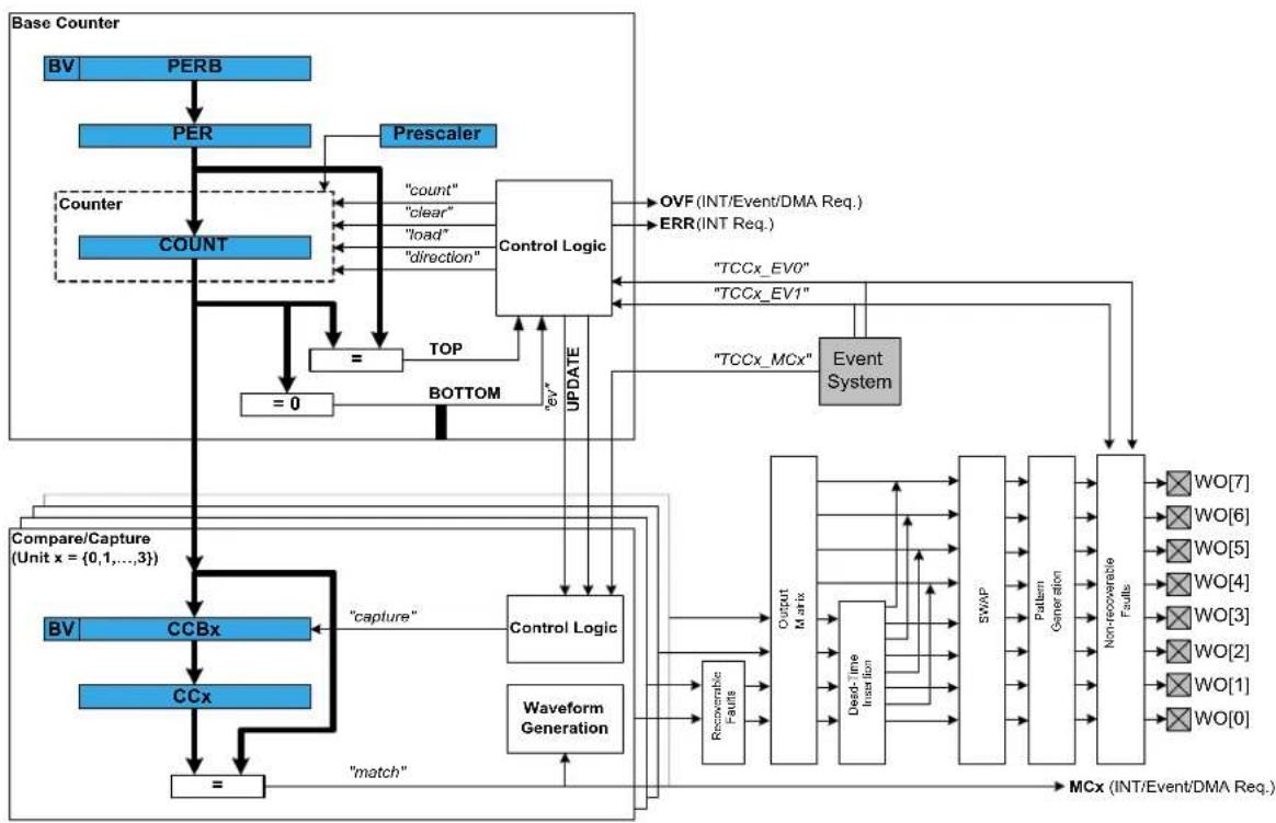
flowchart
graph TD
A["Base Counter"] --> B["BV"]
B --> C["PERB"]
C --> D["PER"]
D --> E["Counter"]
E --> F["COUNT"]
F --> G["="]
G --> H["=0"]
H --> I["BOTTOM"]
I --> J["TOP"]
J --> K["Control Logic"]
K --> L["OVF (INT/Event/DMA Req.)"]
K --> M["ERR (INT Req.)"]
K --> N["TCCx_EV0"]
K --> O["TCCx_EV1"]
K --> P["TCCx_MCx"]
K --> Q["Event System"]
Q --> R["MCx (INT/Event/DMA Req.)"]
S["Compare/Capture (Unit x = {0,1,...,3})"] --> T["BV"]
T --> U["CCBx"]
U --> V["="]
V --> W["CCx"]
W --> X["match"]
X --> Y["capture"]
Y --> Z["Control Logic"]
Z --> AA["Waveform Generation"]
AA --> AB["Recoverable Faults"]
AB --> AC["Output Matrix"]
AC --> AD["Dead Time Intraacy"]
AD --> AE["SWAP"]
AE --> AF["Pattern Generation"]
AF --> AG["Non-recoverable Faults"]
AG --> AH["WO[7"]]
AG --> AI["WO[6"]]
AG --> AJ["WO[5"]]
AG --> AK["WO[4"]]
AG --> AL["WO[3"]]
AG --> AM["WO[2"]]
AG --> AN["WO[1"]]
AG --> AO["WO[0"]]
24.2.1 Functional Description
The TCC module consists of following sections:
- Base Counter
• Compare/Capture channels, with waveform generation
• Waveform extension control and fault detection
• Interface to the event system, DMAC and the interrupt system
The base counter can be configured to either count a prescaled generic clock or events from the event system. (TCEx, with event action configured to counting). The counter value can be used by compare/capture channels which can be set up either in compare mode or capture mode.
In capture mode, the counter value is stored when a configurable event occurs. This mode can be used to generate timestamps used in event capture, or it can be used for the measurement of a periodic input signal's frequency/duty cycle.
In compare mode, the counter value is compared against one or more of the configured channels' compare values. When the counter value coincides with a compare value an action can be taken automatically by the module, such as generating an output event or toggling a pin when used for frequency or PWM signal generation.
Note
The connection of events between modules requires the use of the SAM Event System Driver (EVENTS) to route output event of one module to the input event of another. For more information on event routing, refer to the event driver documentation.
In compare mode, when output signal is generated, extended waveform controls are available, to arrange the compare outputs into specific formats. The Output matrix can change the channel output routing, Pattern generation unit can overwrite the output signal line to specific state. The Fault protection feature of the TCC supports recoverable and non-recoverable faults.
24.2.2 Base Timer/Counter
24.2.2.1 Timer/Counter Size
Each TCC has a counter size of either 16- or 24-bits. The size of the counter determines the maximum value it can count to before an overflow occurs. Table 24-1: Timer counter sizes and their maximum count values on page 578 shows the maximum values for each of the possible counter sizes.
Table 24-1. Timer counter sizes and their maximum count values
| Counter Size Max (Hexadecimal) Max (Decimal) | |
| 16-bit 0xFFFF 65,535 | |
| 24-bit 0xFFFFF 16,777,215 |
The period/top value of the counter can be set, to define counting period. This will allow the counter to overflow when the counter value reaches the period/top value.
24.2.2.2 Timer/Counter Clock and Prescaler
TCC is clocked asynchronously to the system clock by a GCLK (Generic Clock) channel. The GCLK channel can be connected to any of the GCLK generators. The GCLK generators are configured to use one of the available clock sources in the system such as internal oscillator, external crystals etc. - see the Generic Clock driver for more information.
Each TCC module in the SAM D21 has its own individual clock prescaler, which can be used to divide the input clock frequency used by the counter. This prescaler only scales the clock used to provide clock pulses for the counter to count, and does not affect the digital register interface portion of the module, thus the timer registers will synchronized to the raw GCLK frequency input to the module.
As a result of this, when selecting a GCLK frequency and timer prescaler value the user application should consider both the timer resolution required and the synchronization frequency, to avoid lengthy synchronization times of the module if a very slow GCLK frequency is fed into the TCC module. It is preferable to use a higher module GCLK frequency as the input to the timer and prescale this down as much as possible to obtain a suitable counter frequency in latency-sensitive applications.
24.2.2.3 Timer/Counter Control Inputs (Events)
The TCC can take several actions on the occurrence of an input event. The event actions are listed in Table 24-2: TCC module event actions on page 578.
Table 24-2. TCC module event actions
| Event Action Description Applied Event | ||
| TCC_EVENT_ACTION_OFF No action on the event input All | ||
| TCC_EVENT_ACTION_RETRIGGER Re-trigger Counter on event All | ||
| TCC_EVENT_ACTION_NON_RECO Generate Non-Recoverable Fault on event | All | |
| TCC_EVENT_ACTION_START Counter start on event | EV0 | |
| TCC_EVENT_ACTION_DIR_CONTR Counter direction control | EV0 | |
| TCC_EVENT_ACTION_DECREMENT Counter decrement on event | EV0 | |
| TCC_EVENT_ACTION_PERIOD_PU Capture pulse period and pulse width | EV0 | |
| TCC_EVENT_ACTION_PULSE_WID Capture pulse width and pulse period | EV0 | |
| TCC_EVENT_ACTION_STOP Counter stop on event | EV1 | |
| TCC_EVENT_ACTION_COUNT_EVE Counter count on event | EV1 | |
| TCC_EVENT_ACTION_INCREMENT Counter increment on event | EV1 | |
Event Action Description Applied Event
TCC_EVENT_ACTION_COUNT_DU
Counter count during active state
of asynchronous event
24.2.2.4 Timer/Counter Reloading
The TCC also has a configurable reload action, used when a re-trigger event occurs. Examples of a re-trigger event could be the counter reaching the max value when counting up, or when an event from the event system makes the counter to re-trigger. The reload action determines if the prescaler should be reset, and on which clock. The counter will always be reloaded with the value it is set to start counting. The user can choose between three different reload actions, described in Table 24-3: TCC module reload actions on page 579.
Table 24-3. TCC module reload actions
| Reload Action Description | |
| TCC_RELOAD_ACTION_GCLK Reload TCC counter value on next GCLK cycle. Leave prescaler as-is. | |
| TCC_RELOAD_ACTION_PRESC Reloads TCC counter value on next prescaler clock.Leave prescaler as-is. | |
| TCC_RELOAD_ACTION_RESYNC Reload TCC counter value on next GCLK cycle. Clear prescaler to zero. | |
The reload action to use will depend on the specific application being implemented. One example is when an external trigger for a reload occurs; if the TCC uses the prescaler, the counter in the prescaler should not have a value between zero and the division factor. The counter in the TCC module and the counter in the prescaler should both start at zero. If the counter is set to re-trigger when it reaches the max value, this is not the right option to use. In such a case it would be better if the prescaler is left unaltered when the re-trigger happens, letting the counter reset on the next GCLK cycle.
24.2.2.5 One-shot Mode
The TCC module can be configured in one-shot mode. When configured in this manner, starting the timer will cause it to count until the next overflow or underflow condition before automatically halting, waiting to be manually triggered by the user application software or an event from the event system.
24.2.3 Capture Operations
In capture operations, any event from the event system or a pin change can trigger a capture of the counter value. This captured counter value can be used as timestamps for the events, or it can be used in frequency and pulse width capture.
24.2.3.1 Capture Operations - Event
Event capture is a simple use of the capture functionality, designed to create timestamps for specific events. When the input event appears, the current counter value is copied into the corresponding compare/capture register, which can then be read by the user application.
Note that when performing any capture operation, there is a risk that the counter reaches its top value (MAX) when counting up, or the bottom value (zero) when counting down, before the capture event occurs. This can distort the result, making event timestamps to appear shorter than they really are. In this case, the user application should check for timer overflow when reading a capture result in order to detect this situation and perform an appropriate adjustment.
Before checking for a new capture, TCC_STATUS_COUNT_OVERFLOW should be checked. The response to an overflow error is left to the user application, however it may be necessary to clear both the overflow flag and the capture flag upon each capture reading.
24.2.3.2 Capture Operations - Pulse Width
Pulse Width Capture mode makes it possible to measure the pulse width and period of PWM signals. This mode uses two capture channels of the counter. There are two modes for pulse width capture; Pulse Width Period (PWP) and Period Pulse Width (PPW). In PWP mode, capture channel 0 is used for storing the pulse width and capture channel 1 stores the observed period. While in PPW mode, the roles of the two capture channels are reversed.
As in the above example it is necessary to poll on interrupt flags to see if a new capture has happened and check that a capture overflow error has not occurred.
Refer to Timer/Counter Control Inputs (Events) to set up the input event to perform pulse width capture.
24.2.4 Compare Match Operation
In compare match operation, Compare/Capture registers are compared with the counter value. When the timer's count value matches the value of a compare channel, a user defined action can be taken.
24.2.4.1 Basic Timer
A Basic Timer is a simple application where compare match operation is used to determine when a specific period has elapsed. In Basic Timer operations, one or more values in the module's Compare/Capture registers are used to specify the time (in terms of the number of prescaled GCLK cycles, or input events) at which an action should be taken by the microcontroller. This can be an Interrupt Service Routine (ISR), event generation via the event system, or a software flag that is polled from the user application.
24.2.4.2 Waveform Generation
Waveform generation enables the TCC module to generate square waves, or if combined with an external passive low-pass filter, analog waveforms.
24.2.4.3 Waveform Generation - PWM
Pulse width modulation is a form of waveform generation and a signalling technique that can be useful in many applications. When PWM mode is used, a digital pulse train with a configurable frequency and duty cycle can be generated by the TCC module and output to a GPIO pin of the device.
Often PWM is used to communicate a control or information parameter to an external circuit or component. Differing impedances of the source generator and sink receiver circuits is less of an issue when using PWM compared to using an analog voltage value, as noise will not generally affect the signal's integrity to a meaningful extent.
Figure 24-2: Example of PWM in Single-Slope mode, and different counter operations on page 580 illustrates operations and different states of the counter and its output when using the timer in Normal PWM mode(Single Slope). As can be seen, the TOP/PERIOD value is unchanged and is set to MAX. The compare match value is changed at several points to illustrate the resulting waveform output changes. The PWM output is set to normal (i.e. non-inverted) output mode.
Figure 24-2. Example of PWM in Single-Slope mode, and different counter operations

flowchart
graph TD
A["Counter value (COUNT)"] --> B["Repeat counter to zero"]
B --> C["TOP/Period = Max - (PER)"]
C --> D["Compare/Match value (CCx)"]
D --> E["Compare value has been changed (CCx)"]
E --> F["Match"]
F --> G["PWM output"]
Several PWM modes are supported by the TCC module, refer to datasheet for the details on PWM waveform generation.
24.2.4.4 Waveform Generation - Frequency
Normal Frequency Generation is in many ways identical to PWM generation. However, only in Frequency Generation, a toggle occurs on the output when a match on a compare channels occurs.
When the Match Frequency Generation is used, the timer value is reset on match condition, resulting in a variable frequency square wave with a fixed 50% duty cycle.
24.2.5 Waveform Extended Controls
24.2.5.1 Pattern Generation
Pattern insertion allows the TCC module to change the actual pin output level without modifying the compare/match settings. As follow:
Table 24-4. TCC module Output Pattern Generation
| Pattern Description | |
| TCC_OUTPUT_PATTERN_DISABLE Pattern disabled, generate output as is | |
| TCC_OUTPUT_PATTERN_0 Generate pattern 0 on output (keep the output LOW) | |
| TCC_OUTPUT_PATTERN_1 Generate pattern 1 on output (keep the output HIGH) | |
24.2.5.2 Recoverable Faults
The recoverable faults can trigger one or several of following fault actions:
- *Halt* action: The recoverable faults can halt the TCC timer/counter, so that the final output wave is kept at a defined state. When the fault state is removed it's possible to recover the counter and waveform generation. The halt action is defined as follow:
Table 24-5. TCC module Recoverable Fault Halt Actions
| Action Description | |
| TCC_FAULT_HALT_ACTION_DISABLE Halt action is disabled | |
| TCC_FAULT_HALT_ACTION_HW_HALT The timer/counter is halted as long as the corresponding fault is present | |
| TCC_FAULT_HALT_ACTION_SW_HALT The timer/counter is halted until the corresponding fault is removed and fault state cleared by software | |
| TCC_FAULT_HALT_ACTION_NON_RECOVERABLE | Force all the TCC output pins to a pre-defined level, as what Non-Recoverable Fault do |
- *Restart* action: When enabled, the recoverable faults can restart the TCC timer/counter.
- *Keep* action: When enabled, the recoverable faults can keep the corresponding channel output to zero when the fault condition is present.
- *Capture* action: When the recoverable fault occurs, the capture action can time stamps the corresponding fault. The following capture mode is supported:
Table 24-6. TCC module Recoverable Fault Capture Actions
| Action Description | |
| TCC_FAULT_CAPTURE_DISABLE Capture action is disabled | |
| TCC_FAULT_CAPTURE_EACH Equivalent to standard capture operation, on each fault occurrence the time stamp is captured | |
| TCC_FAULT_CAPTURE_MINIMUM Get the minimum time stamped value in all time stamps | |
| TCC_FAULT_CAPTURE_MAXIMUM Get the maximum time stamped value in all time stamps | |
| TCC_FAULT_CAPTURE_SMALLER Time stamp the fault input if the value is smaller than last one | |
| TCC_FAULT_CAPTURE_BIGGER Time stamp the fault input if the value is bigger than last one | |
| TCC_FAULT_CAPTURE_CHANGE Time stamp the fault input if the time stamps changes its increment direction | |
In TCC module, only the first two compare channels (CC0 and CC1) can work with recoverable fault inputs. The corresponding event inputs (TCCx MC0 and TCCx MC1) are then used as fault inputs respectively. The faults are called Fault A and Fault B.
The recoverable fault can be filtered or effected by corresponding channel output. On fault condition there are many other settings that can be chosen. Please refer to data sheet for more details about the recoverable fault operations.
24.2.5.3 Non-Recoverable Faults
The non-recoverable faults force all the TCC output pins to a pre-defined level (can be forced to 0 or 1). The input control signal of non-recoverable fault is from timer/counter event (TCCx EV0 and TCCx EV1). To enable non-recoverable fault, corresponding TCEx event action must be set to non-recoverable fault action (TCC_EVENT_ACTION_NON_RECOVERABLE_FAULT on page 610). Refer to Timer/Counter Control Inputs (Events) to see the available event input action.
24.2.6 Double and Circular Buffering
The pattern, period and the compare channels registers are double buffered. For these options there are effective registers (PATT, PER and CCx) and buffer registers (PATTB, PERB and CCx). When writing to the buffer registers, the values are buffered and will be committed to effective registers on UPDATE condition.
Usually the buffered value is cleared after it's committed, but there is also option to circular the register buffers. The period (PER) and four lowest compare channels register (CCx, x is 0 \~ 3) support this function. When circular buffer is used, on UPDATE the previous period or compare values are copied back into the corresponding period buffer and compare buffers. This way, the register value and its buffer register value is actually switched on UPDATE condition, and will be switched back on next UPDATE condition.
For input capture, the buffer register (CCBx) and the corresponding capture channel register (CCx) act like a FIFO. When regular register (CCx) is empty or read, any content in the buffer register is passed to regular one.
In TCC module driver, when the double buffering write is enabled, any write through tcc_set_top_value(), tcc_set_compare_value() and tcc_set_pattern() will be done to the corresponding buffer register. Then the value in the buffer register will be transferred to the regular register on the next UPDATE condition or by a force UPDATE using tcc_force_double_buffer_update().
24.2.7 Sleep Mode
TCC modules can be configured to operate in any sleep mode, with its "run in standby" function enabled. It can wake up the device using interrupts or perform internal actions with the help of the Event System.
24.3 Special Considerations
24.3.1 Module Features
The features of TCC, such as timer/counter size, number of compare capture channels, number of outputs, are dependent on the TCC module instance being used.
24.3.1.1 SAM D21 TCC Feature List
For SAM D21, the TCC features are as follow:
Table 24-7. TCC module features for SAM D21
| TCC# Match/ Capture Channels | Wave outputs | Counter Size (bits) | Fault Dithering Output Matrix | Dead-Time Insertion | SWAP Pattern | ||
| 0 4 8 24 Y | YYYY | ||||||
| 1 2 4 24 Y | YY | ||||||
| 2 2 2 16 Y | |||||||
24.3.2 Channels VS. Pin outs
As the TCC module may have more waveform output pins than the number of compare/capture channels, the free pins (with number higher than number of channels) will reuse the waveform generated by channels subsequently. E.g., if the number of channels is 4 and number of wave output pins is 8, channel 0 output will be available on out pin 0 and 4, channel 1 output on wave out pin 1 and 5, and so on.
24.4 Extra Information
For extra information see Extra Information for TCC Driver. This includes:
• Acronyms
- Dependencies
- Errata
- Module History
24.5 Examples
For a list of examples related to this driver, see Examples for TCC Driver.
24.6 API Overview
24.6.1 Variable and Type Definitions
24.6.1.1 Type tcc_callback_t
typedef void(* tcc_callback_t )(struct tcc_module *const module)
Type definition for the TCC callback function
24.6.2 Structure Definitions
24.6.2.1 Struct tcc_capture_config
Structure used when configuring TCC channels in capture mode
Table 24-8. Members
| Type Name Description | ||
| enum tcc_channel_function | channel_function[] | Channel functions selection (capture/match) |
24.6.2.2 Struct tcc_config
Configuration struct for a TCC instance. This structure should be initialized by the tcc_get_config_defaults function before being modified by the user application.
Table 24-9. Members
| Type Name Description | ||
| union tcc_config.@412 @412 TCC match/capture configurations. | ||
| struct tcc_counter_config counter Structure for configuring TCC base | timer/counter | |
| bool double_buffering_enabled Set to true to enable double | buffering write. When enabled any write through tcc_set_top_value(), tcc_set_compare_value() and tcc_set_pattern() will direct to the buffer register as buffered value, and the buffered value will be committed to effective register on UPDATE condition, if update is not locked. ^1 | |
| struct tcc_pins_config pins Structure for configuring TCC | output pins | |
| bool run_in_standby When true the module is enabled | during standby | |
| struct tcc_wave_extension_config wave_ext Structure for configuring TCC | waveform extension | |
Notes: ^1 The init values in tcc_config for tcc_init are always filled to effective registers, no matter double buffering enabled or not.
24.6.2.3 Union tcc\_config.\_\_unnamed\_\_
TCC match/capture configurations.
Table 24-10. Members
| Type Name Description | ||
| struct tcc_capture_config capture Helps to configure a TCC channel | in capture mode | |
| struct tcc_match_wave_config | compare | For configuring a TCC channel in compare mode |
| struct tcc_match_wave_config | wave | Serves the same purpose as compare. Used as an alias for compare, when a TCC channel is configured for wave generation |
24.6.2.4 Struct tcc\_counter\_config
Structure for configuring a TCC as a counter
Table 24-11. Members
| Type Name Description | ||
| enum tcc_clock_prescaler | clock_prescaler | Specifies the prescaler value for GCLK_TCC. |
| enum gclk_generator | clock_source | GCLK generator used to clock the peripheral. |
| uint32_t count Value to initialize the count register | ||
| enum tcc_count_direction direction Specifies the direction for the TCC | to count. | |
| bool oneshot When true, counter will be stopped | on the next hardware or software re-trigger event or overflow/underflow | |
| uint32_t period Period/top and period/top buffer | values for counter | |
| enum tcc_reload_action reload_action Specifies the reload or reset time | of the counter and prescaler resynchronization on a re-trigger event for the TCC. | |
24.6.2.5 Struct tcc\_events
Event flags for the tcc_enable_events() and tcc_disable_events().
Table 24-12. Members
| Type Name Description | ||
| bool generate_event_on_channel[] Generate an output event on a | channel capture/match. Specify which channels will generate events | |
| bool generate_event_on_counter_event Generate an output event | on counter boundary. See tcc_event_output_action | |
| bool generate_event_on_counter_overflow Generate an output event on | counter overflow/underflow. | |
| bool generate_event_on_counter_overflow Generate an output event on | Counter retrigger | |
| struct tcc_input_event_config | input_config[] | Input events configuration |
| bool on_event_perform_channel_action[] Perform the configured event | action when an incoming channel event is signalled | |
| bool on_input_event_perform_action[] Perform the configured event | action when an incoming event is signalled. | |
| struct tcc_output_event_config | output_config | Output event configuration |
24.6.2.6 Struct tcc\_input\_event\_config
For configuring an input event
Table 24-13. Members
| Type Name Description | ||
| enum tcc_event_action | action | Event action on incoming event. |
| bool invert Invert incoming event input line. | ||
| bool modify_action Modify event action | ||
24.6.2.7 Struct tcc\_match\_wave\_config
The structure which helps to configure a TCC channel for compare operation and wave generation
Table 24-14. Members
| Type Name Description | ||
| enum tcc_channel_function channel_function[] Channel functions selection | (capture/match) | |
| uint32_t match[] Value to be used for compare | match on each channel. | |
| enum tcc_wave_generation wave_generation Specifies which waveform | generation mode to use. | |
| enum tcc_wave_polarity wave_polarity[] Specifies polarity for match output | waveform generation. | |
| enum tcc_ramp wave_ramp Specifies Ramp mode for | waveform generation. | |
24.6.2.8 Struct tcc\_module
TCC software instance structure, used to retain software state information of an associated hardware module instance.
Note
The fields of this structure should not be altered by the user application; they are reserved only for module-internal use.
Table 24-15. Members
| Type Name Description | ||
| tcc_callback_t | callback[] | Array of callbacks |
| bool double_buffering_enabled | Set to true to write to buffered | registers |
| uint32_t enable_callback_mask | Bit mask for callbacks enabled | |
| Tcc * | hw | Hardware module pointer of the associated Timer/Counter peripheral. |
| uint32_t register_callback_mask | Bit mask for callbacks registered | |
24.6.2.9 Struct tcc\_non\_recoverable\_fault\_config
Table 24-16. Members
| Type Name Description | ||
| uint8_t | filter_value | Fault filter value applied on TCEx event input line (0x0 ~ 0xF). Mustbe 0 when TCEx event is used as synchronous event. |
| enum tcc_fault_state_output output Output | ||
24.6.2.10 Struct tcc\_output\_event\_config
Structure used for configuring an output event
Table 24-17. Members
| Type Name Description | ||
| enumtcc_event_generation_selection | generation_selection It decides which | part of the countercycle the counter event output is generated |
| bool modify_generation_selection A switch to allow enable/disable of | events, without modifying the event output configuration. | |
24.6.2.11 Struct tcc\_pins\_config
Structure which is used when taking wave output from TCC
Table 24-18. Members
| Type Name Description | ||
| bool enable_wave_out_pin[] When true, PWM output pin for the | given channel is enabled. | |
| uint32_t wave_out_pin[] Specifies pin output for each | channel. | |
| uint32_t wave_out_pin_mux[] Specifies MUX setting for each | output channel pin. | |
24.6.2.12 Struct tcc\_recoverable\_fault\_config
Table 24-19. Members
| Type Name Description | ||
| enum tcc_fault_blanking blanking Fault Blanking Start Point for | recoverable Fault | |
| uint8_t | blanking_cycles | Fault blanking value (0 ~ 255), disable input source for several TCC clocks after the detection of the waveform edge. |
| enum tcc_fault_capture_action | capture_action | Capture action for recoverable Fault |
| enum tcc_fault_capture_channel | capture_channel | Channel triggered by recoverable Fault |
| uint8_t | filter_value | Fault filter value applied on MCEx event input line (0x0 ~ 0xF). Must be 0 when MCEx event is used as synchronous event. Apply to bothrecoverable and non-recoverable fault. |
| enum tcc_fault_halt_action halt_action Halt action for recoverable Fault | ||
| bool keep Set to true to enable keep action | (keep until end of TCC cycle) | |
| bool qualification Set to true to enable input | qualification (disable input when output is inactive) | |
| bool restart Set to true to enable restart action | ||
| enum tcc_fault_source source Specifies if the event input | generates recoverable Fault. The event system channel connected to MCEx event input must be configured as asynchronous. | |
24.6.2.13 Struct tcc\_wave\_extension\_config
This structure is used to specify the waveform extension features for TCC
Table 24-20. Members
| Type Name Description | ||
| bool invert[] Invert waveform final outputs lines. | ||
| struct tcc_non_recoverable_fault_config | non_recoverable_fault[] Configuration for non-recoverable faults. | |
| struct tcc_recoverable_fault_config recoverable_fault[] Configuration for recoverable faults. | ||
24.6.3 Macro Definitions
24.6.3.1 Module status flags
TCC status flags, returned by tcc_get_status() and cleared by tcc_clear_status().
Macro TCC_STATUS_CHANNEL_MATCH_CAPTURE
#define TCC_STATUS_CHANNEL_MATCH_CAPTURE(ch) \
(1UL << (ch))
Timer channel ch (0 \~ 3) has matched against its compare value, or has captured a new value
Macro TCC_STATUS_CHANNEL_OUTPUT
#define TCC_STATUS_CHANNEL_OUTPUT(ch) \
(1UL << ((ch)+8))
Timer channel ch (0 \~ 3) match/compare output state.
Macro TCC_STATUS_NON_RECOVERABLE_FAULT_OCCUR
#define TCC_STATUS_NON_RECOVERABLE_FAULT_OCCUR(x) \
(1UL << ((x)+16))
A Non-Recoverable Fault x (0 \~ 1) has occurred
Macro TCC_STATUS_RECOVERABLE_FAULT_OCCUR
#define TCC_STATUS_RECOVERABLE_FAULT_OCCUR(n) \
(1UL << ((n)+18))
A Recoverable Fault n (0 \~ 1 representing A \~ B) has occurred
Macro TCC_STATUS_NON_RECOVERABLE_FAULT_PRESENT
#define TCC_STATUS_NON_RECOVERABLE_FAULT_PRESENT(x) \
(1UL << ((x)+20))
The Non-Recoverable Fault x (0 \~ 1) input is present
Macro TCC_STATUS_RECOVERABLE_FAULT_PRESENT
#define TCC_STATUS_RECOVERABLE_FAULT_PRESENT(n) \
(1UL << ((n)+22))
A Recoverable Fault n (0 \~ 1 representing A \~ B) is present
Macro TCC_STATUS_SYNC_READY
#define TCC_STATUS_SYNC_READY (1UL << 23)
Timer registers synchronization has completed, and the synchronized count value may be read.
Macro TCC_STATUS_CAPTURE_OVERFLOW
#define TCC_STATUS_CAPTURE_OVERFLOW (1UL << 24)
A new value was captured before the previous value was read, resulting in lost data.
Macro TCC_STATUS_COUNTER_EVENT
#define TCC_STATUS_COUNTER_EVENT (1UL << 25)
A counter event occurred
Macro TCC_STATUS_COUNTER_RETRIGGERED
#define TCC_STATUS_COUNTER_RETRIGGERED (1UL << 26)
A counter retrigger occurred
Macro TCC_STATUS_COUNT_OVERFLOW
#define TCC_STATUS_COUNT_OVERFLOW (1UL << 27)
The timer count value has overflowed from its maximum value to its minimum when counting upward, or from its minimum value to its maximum when counting downward.
Macro TCC_STATUS_RAMP_CYCLE_INDEX
#define TCC_STATUS_RAMP_CYCLE_INDEX (1UL << 28)
Ramp period cycle index. In ramp operation, each two period cycles are marked as cycle A and B, the index 0 represents cycle A and 1 represents cycle B.
Macro TCC_STATUS_STOPPED
#define TCC_STATUS_STOPPED (1UL << 29)
The counter has been stopped (due to disable, stop command or one-shot)
24.6.3.2 Macro _TCC_CHANNEL_ENUM_LIST
#define _TCC_CHANNEL_ENUM_LIST(type) \
MREPEAT(TCC_NUM_CHANNELS, _TCC_ENUM, type##_CHANNEL)
24.6.3.3 Macro _TCC_ENUM
#define _TCC_ENUM(n, type) \
TCC_##type##_##n,
24.6.3.4 Macro _TCC_WO_ENUM_LIST
#define _TCC_WO_ENUM_LIST(type) \
MREPEAT(TCC_NUM_WAVE_OUTPUTS, _TCC_ENUM, type)
24.6.3.5 Macro TCC\_NUM\_CHANNELS
define TCC_NUM_CHANNELS 4
Max number of channels supported by the driver (Channel index from 0 to TCC_NUM_CHANNELS - 1).
24.6.3.6 Macro TCC\_NUM\_FAULTS
define TCC_NUM_FAULTS 2
Max number of (recoverable) faults supported by the driver.
24.6.3.7 Macro TCC\_NUM\_WAVE\_OUTPUTS
define TCC_NUM_WAVE_OUTPUTS 8
Max number of wave outputs lines supported by the driver (Output line index from 0 to TCC_NUM_WAVE_OUTPUTS - 1).
24.6.4 Function Definitions
24.6.4.1 Driver Initialization and Configuration
Function tcc\_is\_syncing()
Determines if the hardware module is currently synchronizing to the bus.
bool tcc_is_syncing( const struct tcc_module *const module_inst)
Checks to see if the underlying hardware peripheral module is currently synchronizing across multiple clock domains to the hardware bus. This function can be used to delay further operations on a module until such time that it is ready, to prevent blocking delays for synchronization in the user application.
Table 24-21. Parameters
| Data direction Parameter name Description | |
| [in] module_inst Pointer to the software module | instance struct |
Returns
Synchronization status of the underlying hardware module.
Table 24-22. Return Values
| Return value Description | |
| true If the module has completed synchronization |
Return value Description
false If the module synchronization is ongoing
Function tcc\_get\_config\_defaults()
Initializes config with predefined default values.
void tcc_get_config_defaults(
struct tcc_config *const config,
Tcc *const hw)
This function will initialize a given TCC configuration structure to a set of known default values. This function should be called on any new instance of the configuration structures before being modified by the user application.
The default configuration is as follows:
- Don't run in standby
- When setting top, compare or pattern by API, do double buffering write
• The base timer/counter configurations:
• GCLK generator 0 clock source
- No prescaler
• GCLK reload action
- Count upward
- Don't perform one-shot operations
- Counter starts on 0
• Period/top value set to maximum
• The match/capture configurations:
- All Capture compare channel value set to 0
- No capture enabled (all channels use compare function)
• Normal frequency wave generation
• Waveform generation polarity set to 0 - Don't perform ramp on waveform
• The waveform extension configurations:
- No recoverable fault is enabled, fault actions are disabled, filter is set to 0
- No non-recoverable fault state output is enabled and filter is 0
• No inversion of waveform output
• No channel output enabled
• No PWM pin output enabled
• Pin and Mux configuration not set
Table 24-23. Parameters
| Data direction Parameter name Description | |
| [out] config Pointer to a TCC module | configuration structure to set |
| [in] hw Pointer to the TCC hardware | module |
Function tcc\_init()
Initializes a hardware TCC module instance.
enum status_code tcc_init(
struct tcc_module *const module_inst,
Tcc *const hw,
const struct tcc_config *const config)
Enables the clock and initializes the given TCC module, based on the given configuration values
Table 24-24. Parameters
| Data direction Parameter name Description | |
| [in, out] module_inst Pointer to the software module | instance struct |
| [in] hw Pointer to the TCC hardware | module |
| [in] config Pointer to the TCC configuration | options struct |
Returns
Status of the initialization procedure.
Table 24-25. Return Values
| Return value Description | |
| STATUS_OK The module was initialized successfully | |
| STATUS_BUSY Hardware module was busy when the initialization procedure was attempted | |
| STATUS_INVALID_ARG An invalid configuration option or argument was supplied | |
| STATUS_ERR_DENIED Hardware module was already enabled | |
24.6.4.2 Event Management
Function tcc\_enable\_events()
Enables the TCC module event input or output.
enum status_code tcc_enable_events(
struct tcc_module *const module_inst,
struct tcc_events *const events)
Enables one or more input or output events to or from the TCC module. See tcc_events for a list of events this module supports.
Note
Events cannot be altered while the module is enabled.
Table 24-26. Parameters
| Data direction Parameter name Description | |
| [in] module_inst Pointer to the software module | instance struct |
| [in] events Struct containing flags of events to | enable or configure |
Returns
Status of the events setup procedure.
Table 24-27. Return Values
| Return value Description | |
| STATUS_OK The module was initialized successfully | |
| STATUS_INVALID_ARG An invalid configuration option or argument was supplied |
Function tcc\_disable\_events()
Disables the event input or output of a TCC instance.
void tcc_disable_events(
struct tcc_module *const module_inst,
struct tcc_events *const events)
Disables one or more input or output events for the given TCC module. See tcc_events for a list of events this module supports.
Note
Events cannot be altered while the module is enabled.
Table 24-28. Parameters
| Data direction Parameter name Description | |
| [in] module_inst Pointer to the software module | instance struct |
| [in] events Struct containing flags of events to | disable |
Enables a TCC module that has been previously initialized. The counter will start when the counter is enabled.
Note
When the counter is configured to re-trigger on an event, the counter will not start until the next incoming event appears. Then it restarts on any following event.
Table 24-29. Parameters
| Data direction Parameter name Description | |
| [in] module_inst Pointer to the software module | instance struct |
Function tcc\_disable()
Disables the TCC module.
void tcc_disable(
const struct tcc_module *const module_inst)
Disables a TCC module and stops the counter.
Table 24-30. Parameters
| Data direction Parameter name Description | |
| [in] module_inst Pointer to the software module | instance struct |
Function tcc\_reset()
Resets the TCC module.
void tcc_reset(
const struct tcc_module *const module_inst)
Resets the TCC module, restoring all hardware module registers to their default values and disabling the module. The TCC module will not be accessible while the reset is being performed.
Note
When resetting a 32-bit counter only the master TCC module's instance structure should be passed to the function.
Table 24-31. Parameters
| Data direction Parameter name Description | |
| [in] module_inst Pointer to the software module | instance struct |
24.6.4.4 Set/Toggle Count Direction
Function tcc\_set\_count\_direction()
Sets the TCC module count direction.
void tcc_set_count_direction(
const struct tcc_module *const module_inst,
enum tcc_count_direction dir)
Sets the count direction of an initialized TCC module. The specified TCC module can remain running or stopped.
Table 24-32. Parameters
| Data direction Parameter name Description | |
| [in] module_inst Pointer to the software module | instance struct |
| [in] dir New timer count direction to set |
Function tcc\_toggle\_count\_direction()
Toggles the TCC module count direction.
void tcc_toggle_count_direction( const struct tcc_module *const module_inst)
Toggles the count direction of an initialized TCC module. The specified TCC module can remain running or stopped.
Table 24-33. Parameters
| Data direction Parameter name Description | |
| [in] module_inst Pointer to the software module | instance struct |
24.6.4.5 Get/Set Count Value
Function tcc\_get\_count\_value()
Get count value of the given TCC module.
uint32_t tcc_get_count_value(
const struct tcc_module *const module_inst)
Retrieves the current count value of a TCC module. The specified TCC module can remain running or stopped.
Table 24-34. Parameters
| Data direction Parameter name Description | |
| [in] module_inst Pointer to the software module | instance struct |
Returns
Count value of the specified TCC module.
Function tcc\_set\_count\_value()
Sets count value for the given TCC module.
enum status_code tcc_set_count_value(
const struct tcc_module *const module_inst,
const uint32_t count)
Sets the timer count value of an initialized TCC module. The specified TCC module can remain running or stopped.
Table 24-35. Parameters
| Data direction Parameter name Description | |
| [in] module_inst Pointer to the software module | instance struct |
| [in] count New timer count value to set |
Returns
Status which indicates whether the new value is set.
Table 24-36. Return Values
| Return value Description | |
| STATUS_OK The timer count was updated successfully | |
| STATUS_ERR_INVALID_ARG An invalid timer counter size was specified | |
24.6.4.6 Stop/Restart Counter
Function tcc\_stop\_counter()
Stops the counter.
void tcc_stop_counter(
const struct tcc_module *const module_inst)
This function will stop the counter. When the counter is stopped the value in the count register is set to 0 if the counter was counting up, or max or the top value if the counter was counting down.
Table 24-37. Parameters
| Data direction Parameter name Description | |
| [in] module_inst Pointer to the software module | instance struct |
Function tcc\_restart\_counter()
Starts the counter from beginning.
void tcc_restart_counter( const struct tcc_module *const module_inst)
Restarts an initialized TCC module's counter.
Table 24-38. Parameters
| Data direction Parameter name Description | |
| [in] module_inst Pointer to the software module | instance struct |
24.6.4.7 Get/Set Compare/Capture Register
Function tcc\_get\_capture\_value()
Gets the TCC module capture value.
uint32_t tcc_get_capture_value(
const struct tcc_module *const module_inst,
const enum tcc_match_capture_channel channel_index)
Retrieves the capture value in the indicated TCC module capture channel.
Table 24-39. Parameters
| Data direction Parameter name Description | |
| [in] module_inst Pointer to the software module | instance struct |
| [in] channel_index Index of the Compare Capture | channel to read |
Returns
Capture value stored in the specified timer channel.
Function tcc\_set\_compare\_value()
Sets a TCC module compare value.
enum status_code tcc_set_compare_value(
const struct tcc_module *const module_inst,
const enum tcc_match_capture_channel channel_index,
const uint32_t compare)
Writes a compare value to the given TCC module compare/capture channel.
If double buffering is enabled it always write to the buffer register. The value will then be updated immediately by calling tcc_force_double_buffer_update(), or be updated when the lock update bit is cleared and the UPDATE condition happen.
Table 24-40. Parameters
| Data direction Parameter name Description | |
| [in] module_inst Pointer to the software module | instance struct |
| [in] channel_index Index of the compare channel to | write to |
| [in] compare New compare value to set |
Returns
Status of the compare update procedure.
Table 24-41. Return Values
| Return value Description | |
| STATUS_OK The compare value was updated successfully | |
| STATUS_ERR_INVALID_ARG An invalid channel index | was supplied or compare value exceed resolution |
24.6.4.8 Set Top Value
Function tcc\_set\_top\_value()
Set the timer TOP/PERIOD value.
enum status_code tcc_set_top_value(
const struct tcc_module *const module_inst,
const uint32_t top_value)
This function writes the given value to the PER/PERB register.
If double buffering is enabled it always write to the buffer register (PERB). The value will then be updated immediately by calling tcc_force_double_buffer_update(), or be updated when the lock update bit is cleared and the UPDATE condition happen.
When using MFRQ, the top value is defined by the CC0 register value and the PER value is ignored, so tcc_set_compare_value(module, channel_0, value) must be used instead of this function to change the actual top value in that case. For all other waveforms operation the top value is defined by PER register value.
Table 24-42. Parameters
| Data direction Parameter name Description | |
| [in] module_inst Pointer to the software module | instance struct |
| [in] top_value New value to be loaded into the | PER/PERB register |
Returns
Status of the TOP set procedure.
Table 24-43. Return Values
| Return value Description | |
| STATUS_OK The timer TOP value was updated successfully | |
| STATUS_ERR_INVALID_ARG An invalid channel index | was supplied or top/period value exceed resolution |
24.6.4.9 Set Output Pattern
Function tcc\_set\_pattern()
Sets the TCC module waveform output pattern.
enum status_code tcc_set_pattern(
const struct tcc_module *const module_inst,
const uint32_t line_index,
const enum tcc_output_pattern pattern)
Force waveform output line to generate specific pattern (0, 1 or as is).
If double buffering is enabled it always write to the buffer register. The value will then be updated immediately by calling tcc_force_double_buffer_update(), or be updated when the lock update bit is cleared and the UPDATE condition happen.
Table 24-44. Parameters
| Data direction Parameter name Description | |
| [in] module_inst Pointer to the software module | instance struct |
| [in] line_index Output line index | |
| [in] pattern Output pattern to use | (tcc_output_pattern) |
Returns
Status of the pattern set procedure.
Table 24-45. Return Values
| Return value Description | |
| STATUS_OK The PATT register is updated successfully | |
| STATUS_ERR_INVALID_ARG An invalid line index was supplied |
24.6.4.10 Set Ramp Index
Function tcc\_set\_ramp\_index()
Sets the TCC module ramp index on next cycle.
void tcc_set_ramp_index(
const struct tcc_module *const module_inst,
const enum tcc_ramp_index ramp_index)
In RAMP2 and RAMP2A operation, we can force either cycle A or cycle B at the output, on the next clock cycle. When ramp index command is disabled, cycle A and cycle B will appear at the output, on alternate clock cycles. See tcc_ramp.
Table 24-46. Parameters
| Data direction Parameter name Description | |
| [in] module_inst Pointer to the software module | instance struct |
| [in] ramp_index Ramp index (tcc_ramp_index) of | the next cycle |
24.6.4.11 Status Management
Function tcc\_is\_running()
Checks if the timer/counter is running.
bool tcc_is_running(
struct tcc_module *const module_inst)
Table 24-47. Parameters
| Data direction Parameter name Description | |
| [in] module_inst Pointer to the TCC software | instance struct |
Returns
Status which indicates whether the module is running.
Table 24-48. Return Values
| Return value Description | |
| true The timer/counter is running. | |
| false The timer/counter is stopped. |
Function tcc\_get\_status()
Retrieves the current module status.
uint32_t tcc_get_status(
struct tcc_module *const module_inst)
Retrieves the status of the module, giving overall state information.
Table 24-49. Parameters
| Data direction Parameter name Description | |
| [in] module_inst Pointer to the TCC software | instance struct |
Returns
Bitmask of TCC_STATUS_* flags
Table 24-50. Return Values
| Return value Description | |
| TCC_STATUS_CHANNEL_MATCH_CAPTURE(n) Channel n match/capture has occurred | |
| TCC_STATUS_CHANNEL_OUTPUT(n) Channel n match/capture output state | |
| TCC_STATUS_NON_RECOVERABLE_FAULT_OCCUR | Non-recoverable fault x has occurred |
| TCC_STATUS_RECOVERABLE_FAULT_OCCUR(n) | Recoverable fault n has occurred |
| TCC_STATUS_NON_RECOVERABLE_FAULT_PRESEN | Non-recoverable fault x input present |
| TCC_STATUS_RECOVERABLE_FAULT_PRESENT(n) | Recoverable fault n input present |
| TCC_STATUS_SYNC_READY | None of register is syncing |
| TCC_STATUS_CAPTURE_OVERFLOW | Timer capture data has overflowed |
| TCC_STATUS_COUNTER_EVENT | Timer counter event has occurred |
| TCC_STATUS_COUNT_OVERFLOW | Timer count value has overflowed |
| TCC_STATUS_COUNTER_RETRIGGERED | Timer counter has been retriggered |
| TCC_STATUS_STOP | Timer counter has been stopped |
| TCC_STATUS_RAMP_CYCLE_INDEX | Wave ramp index for cycle |
Function tcc\_clear\_status()
Clears a module status flag.
void tcc_clear_status(
struct tcc_module *const module_inst,
const uint32_t status_flags)
Clears the given status flag of the module.
Table 24-51. Parameters
| Data direction Parameter name Description | ||
| [in] | module_inst | Pointer to the TCC software instance struct |
| [in] | status_flags | Bitmask of TCC_STATUS_* flags to clear |
24.6.4.12 Double Buffering Management
Function tcc\_enable\_double\_buffering()
Enable TCC double buffering write.
void tcc_enable_double_buffering(
struct tcc_module *const module_inst)
When double buffering write is enabled, following function will write values to buffered registers instead of effective ones (buffered):
• PERB: through tcc_set_top_value()
- CCBx(x is 0\~3): through tcc_set_compare_value()
- PATTB: through tcc_set_pattern()
Then on UPDATE condition the buffered registers are committed to regular ones to take effect.
Table 24-52. Parameters
| Data direction Parameter name Description | |
| [in] module_inst Pointer to the TCC software | instance struct |
Function tcc\_disable\_double\_buffering()
Disable TCC double buffering Write.
void tcc_disable_double_buffering(
struct tcc_module *const module_inst)
When double buffering write is disabled, following function will write values to effective registers (not buffered):
• PER: through tcc_set_top_value()
- CCx(x is 0\~3): through tcc_set_compare_value()
- PATT: through tcc_set_pattern()
Note
This function does not lock double buffer update, which means on next UPDATE condition the last written buffered values will be committed to take effect. Invoke tcc_lock_double_buffer_update() before this function to disable double buffering update, if this change is not expected.
Table 24-53. Parameters
| Data direction Parameter name Description | |
| [in] module_inst Pointer to the TCC software | instance struct |
Function tcc\_lock\_double\_buffer\_update()
Lock the TCC double buffered registers updates.
void tcc_lock_double_buffer_update(
struct tcc_module *const module_inst)
Locks the double buffered registers so they will not be updated through their buffered values on UPDATE conditions.
Table 24-54. Parameters
| Data direction Parameter name Description | |
| [in] module_inst Pointer to the TCC software | instance struct |
Function tcc\_unlock\_double\_buffer\_update()
Unlock the TCC double buffered registers updates.
void tcc_unlock_double_buffer_update(
struct tcc_module *const module_inst)
Unlock the double buffered registers so they will be updated through their buffered values on UPDATE conditions.
Table 24-55. Parameters
| Data direction Parameter name Description | |
| [in] module_inst Pointer to the TCC software | instance struct |
Function tcc\_force\_double\_buffer\_update()
Force the TCC double buffered registers to update once.
void tcc_force_double_buffer_update(
struct tcc_module *const module_inst)
Table 24-56. Parameters
| Data direction Parameter name Description | |
| [in] module_inst Pointer to the TCC software | instance struct |
Function tcc\_enable\_circular\_buffer\_top()
Enable Circular option for double buffered Top/Period Values.
void tcc_enable_circular_buffer_top(
struct tcc_module *const module_inst)
Enable circular option for the double buffered top/period values. On each UPDATE condition, the contents of PERB and PER are switched, meaning that the contents of PERB are transferred to PER and the contents of PER are transferred to PERB.
Table 24-57. Parameters
| Data direction Parameter name Description | |
| [in] module_inst Pointer to the TCC software | instance struct |
Function tcc\_disable\_circular\_buffer\_top()
Disable Circular option for double buffered Top/Period Values.
void tcc_disable_circular_buffer_top(
struct tcc_module *const module_inst)
Stop circularing the double buffered top/period values.
Table 24-58. Parameters
| Data direction Parameter name Description | |
| [in] module_inst Pointer to the TCC software | instance struct |
Function tcc\_set\_double\_buffer\_top\_values()
Set the timer TOP/PERIOD value and buffer value.
enum status_code tcc_set_double_buffer_top_values(
const struct tcc_module *const module_inst,
const uint32_t top_value,
const uint32_t top_buffer_value)
This function writes the given value to the PER and PERB register. Usually as preparation for double buffer or circulated double buffer (circular buffer).
When using MFRQ, the top values are defined by the CC0 and CCB0, the PER and PERB values are ignored, so tcc_set_double_buffer_compare_values(module, channel_0, value, buffer) must be used instead of this function to change the actual top values in that case. For all other waveforms operation the top values are defined by PER and PERB registers values.
Table 24-59. Parameters
| Data direction Parameter name Description | |
| [in] module_inst Pointer to the software module | instance struct |
| [in] top_value New value to be loaded into the | PER register |
| [in] top_buffer_value New value to be loaded into the | PERB register |
Returns
Status of the TOP set procedure.
Table 24-60. Return Values
| Return value Description | |
| STATUS_OK The timer TOP value was updated successfully | |
| STATUS_ERR_INVALID_ARG An invalid channel index | was supplied or top/period value exceed resolution |
Function tcc\_enable\_circular\_buffer\_compare()
Enable Circular option for double buffered Compare Values.
enum status_code tcc_enable_circular_buffer_compare(
struct tcc_module *const module_inst,
enum tcc_match_capture_channel channel_index)
Enable circular option for the double buffered channel compare values. On each UPDATE condition, the contents of CCBx and CCx are switched, meaning that the contents of CCBx are transferred to CCx and the contents of CCx are transferred to CCBx.
Table 24-61. Parameters
| Data direction Parameter name Description | |
| [in] module_inst Pointer to the TCC software | instance struct |
| [in] channel_index Index of the compare channel to | set up to |
Table 24-62. Return Values
| Return value Description | |
| STATUS_OK The module was initialized successfully | |
| STATUS_INVALID_ARG An invalid channel index is supplied | |
Function tcc\_disable\_circular\_buffer\_compare()
Disable Circular option for double buffered Compare Values.
enum status_code tcc_disable_circular_buffer_compare(
struct tcc_module *const module_inst,
enum tcc_match_capture_channel channel_index)
Stop circularing the double buffered compare values.
Table 24-63. Parameters
| Data direction Parameter name Description | |
| [in] module_inst Pointer to the TCC software | instance struct |
| [in] channel_index Index of the compare channel to | set up to |
Table 24-64. Return Values
| Return value Description | |
| STATUS_OK The module was initialized successfully | |
| STATUS_INVALID_ARG An invalid channel index is supplied | |
Function tcc\_set\_double\_buffer\_compare\_values()
Sets a TCC module compare value and buffer value.
enum status_code tcc_set_double_buffer_compare_values(
struct tcc_module *const module_inst,
enum tcc_match_capture_channel channel_index,
const uint32_t compare,
const uint32_t compare_buffer)
Writes compare value and buffer to the given TCC module compare/capture channel. Usually as preparation for double buffer or circulated double buffer (circular buffer).
Table 24-65. Parameters
| Data direction Parameter name Description | |
| [in] module_inst Pointer to the software module | instance struct |
| [in] channel_index Index of the compare channel to | write to |
| [in] compare New compare value to set | |
| [in] compare_buffer New compare buffer value to set |
Returns
Status of the compare update procedure.
Table 24-66. Return Values
| Return value Description | |
| STATUS_OK The compare value was updated successfully | |
| STATUS_ERR_INVALID_ARG An invalid channel index | was supplied or compare value exceed resolution |
24.6.5 Enumeration Definitions
24.6.5.1 Enum tcc\_callback
Enum for the possible callback types for the TCC module.
Table 24-67. Members
| Enum value Description | |
| TCC_CALLBACK_OVERFLOW Callback for TCC overflow. | |
| TCC_CALLBACK_RETRIGGER Callback for TCC Retrigger. | |
| TCC_CALLBACK_COUNTER_EVENT Callback for TCC counter event. | |
| TCC_CALLBACK_ERROR | Callback for capture overflow error. |
| TCC_CALLBACK_FAULTA | Callback for Recoverable Fault A. |
| TCC_CALLBACK_FAULTB | Callback for Recoverable Fault B. |
| TCC_CALLBACK_FAULT0 | Callback for Non-Recoverable Fault. 0 |
| TCC_CALLBACK_FAULT1 | Callback for Non-Recoverable Fault. 1 |
| TCC_CALLBACK_CHANNEL_n | Channel callback type table for TCCEach TCC module may contain severalcallback types for channels; each channelwill have its own callback type in the table,with the channel index number substitutedfor "n" in the channel callback type (e.g.TCC_MATCH_CAPTURE_CHANNEL_0). |
24.6.5.2 Enum tcc\_channel\_function
To set a timer channel either in compare or in capture mode
Table 24-68. Members
| Enum value Description | |
| TCC_CHANNEL_FUNCTION_COMPARE | TCC channel performs compare operation. |
| TCC_CHANNEL_FUNCTION_CAPTURE | TCC channel performs capture operation. |
24.6.5.3 Enum tcc\_clock\_prescaler
This enum is used to choose the clock prescaler configuration. The prescaler divides the clock frequency of the TCC module to operate TCC at a slower clock rate.
Table 24-69. Members
| Enum value Description | |
| TCC_CLOCK_PRESCALER_DIV1 Divide clock by 1 | |
| TCC_CLOCK_PRESCALER_DIV2 Divide clock by 2 | |
| TCC_CLOCK_PRESCALER_DIV4 Divide clock by 4 | |
| TCC_CLOCK_PRESCALER_DIV8 Divide clock by 8 | |
| TCC_CLOCK_PRESCALER_DIV16 Divide clock by 16 | |
| TCC_CLOCK_PRESCALER_DIV64 Divide clock by 64 | |
| TCC_CLOCK_PRESCALER_DIV256 Divide clock by 256 | |
| TCC_CLOCK_PRESCALER_DIV1024 Divide clock by 1024 |
24.6.5.4 Enum tcc\_count\_direction
Used when selecting the Timer/Counter count direction.
Table 24-70. Members
| Enum value Description | |
| TCC_COUNT_DIRECTION_UP Timer should count upward | |
| TCC_COUNT_DIRECTION_DOWN Timer should count downward | |
24.6.5.5 Enum tcc\_event0\_action
Event action to perform when the module is triggered by event0.
Table 24-71. Members
| Enum value Description | |
| TCC_EVENT0_ACTION_OFF No event action. | |
| TCC_EVENT0_ACTION_RETRIGGER Re-trigger Counter on event. | |
| TCC_EVENT0_ACTION_COUNT_EVENT Count events (increment or decrement,depending on count direction) | |
| TCC_EVENT0_ACTION_START Start counter on event. | |
| TCC_EVENT0_ACTION_INCREMENT Increment counter on event. | |
| TCC_EVENT0_ACTION_COUNT_DURING_ACTIVE Count during active state of asynchronous event. | |
| TCC_EVENT0_ACTION_NON_RECOVERABLE_FAULT Generate Non-Recoverable Fault on event. | |
24.6.5.6 Enum tcc\_event1\_action
Event action to perform when the module is triggered by event1.
Table 24-72. Members
| Enum value Description | |
| TCC_EVENT1_ACTION_OFF No event action. | |
| TCC_EVENT1_ACTION_RETRIGGER Re-trigger Counter on event. | |
| TCC_EVENT1_ACTION_DIR_CONTROL The event source must be an asynchronous event, input value will override the direction settings If TCEINVx is 0 and input event is LOW: counter will count up. If TCEINVx is 0 and input event is HIGH: counter will count down | |
| TCC_EVENT1_ACTION_STOP Stop counter on event. | |
| TCC_EVENT1_ACTION_DECREMENT Decrement on event | |
| TCC_EVENT1_ACTION_PERIOD_PULSE_WIDTH_CAPTURE Store period in capture register 0, pulse width in capture register 1. | |
| TCC_EVENT1_ACTION_PULSE_WIDTH_PERIOD_CAPTURE Store pulse width in capture register 0, period in capture register 1. | |
| TCC_EVENT1_ACTION_NON_RECOVERABLE_FAULT Generate Non-Recoverable Fault on event. | |
24.6.5.7 Enum tcc\_event\_action
Event action to perform when the module is triggered by events.
Table 24-73. Members
| Enum value Description | |
| TCC_EVENT_ACTION_OFF No event action. | |
| TCC_EVENT_ACTION_STOP Stop counting, the counter will maintainits current value, waveforms are set to a defined Non-Recoverable State output (tcc_non_recoverable_state_output). | |
| TCC_EVENT_ACTION_RETRIGGER Re-trigger counter on event, may generate an event if the re-trigger event output is enabled. | |
| Note | When re-trigger event action is enabled, enabling the counter will not start until the next incoming event appears. |
| TCC_EVENT_ACTION_START Start counter when previously stopped.Start counting on the event rising edge.Further events will not restart the counter; the counter keeps on counting using prescaled GCLK_TCCx, until it reaches TOP or Zero depending on the direction | |
| TCC_EVENT_ACTION_COUNT_EVENT Count events; ie; Increment or decrementdepending on count direction | |
| TCC_EVENT_ACTION_DIR_CONTROL The event source must be an asynchronous event, input value will overrides the direction settings (input low: counting up, input high counting down). | |
| TCC_EVENT_ACTION_INCREMENT Increment the counter on event, irrespective of count direction | |
| TCC_EVENT_ACTION_DECREMENT | Decrement the counter on event, irrespective of count direction |
| TCC_EVENT_ACTION_COUNT_DURING_ACTIVE Count during active state of asynchronous event. In this case, depending on the count direction, the count will be incremented or decremented on each prescaled GCLK_TCCx, as long as the input event remains active | |
| TCC_EVENT_ACTION_PERIOD_PULSE_WIDTH_CAPTURE | Store period in capture register 0, pulse width in capture register 1. |
| TCC_EVENT_ACTION_PULSE_WIDTH_PERIOD_CAPTURE | Store pulse width in capture register 0, period in capture register 1. |
| TCC_EVENT_ACTION_NON_RECOVERABLE_FAULT Generate Non-Recoverable Fault on event. | |
24.6.5.8 Enum tcc\_event\_generation\_selection
This enum is used to define the point at which the counter event is generated
Table 24-74. Members
| Enum value Description | |
| TCC_EVENT_GENERATION_SELECTION_START Counter Event is generated when a new counter cycle starts | |
| TCC_EVENT_GENERATION_SELECTION_END Counter Event is generated when a counter cycle ends | |
| TCC_EVENT_GENERATION_SELECTION_BETWEEN Counter Event is generated when a counter cycle ends, except for the first and last cycles | |
| TCC_EVENT_GENERATION_SELECTION_BOUNDARY Counter Event is generated when a new counter cycle starts or ends | |
24.6.5.9 Enum tcc\_fault\_blanking
Table 24-75. Members
| Enum value Description | |
| TCC_FAULT_BLANKING_DISABLE No blanking | |
| TCC_FAULT_BLANKING_RISING_EDGE Blanking applied from rising edge of the output waveform | |
| TCC_FAULT_BLANKING_FALLING_EDGE Blanking applied from falling edge of the output waveform | |
| TCC_FAULT_BLANKING_BOTH_EDGE Blanking applied from each toggle of the output waveform | |
24.6.5.10 Enum tcc\_fault\_capture\_action
Table 24-76. Members
| Enum value Description | |
| TCC_FAULT_CAPTURE_DISABLE | Capture disabled |
| TCC_FAULT_CAPTURE_EACH | Capture on Fault, each value is captured |
| TCC_FAULT_CAPTURE_MINIMUM Capture the minimum detection, but notify on smaller ones | |
| TCC_FAULT_CAPTURE_MAXIMUM Capture the maximum detection, but notify on bigger ones | |
| TCC_FAULT_CAPTURE_SMALLER Capture if the value is smaller than last, notify event or interrupt if previous stamp is confirmed to be "local minimum" (not bigger than current stamp) | |
| TCC_FAULT_CAPTURE_BIGGER Capture if the value is bigger than last, notify event or interrupt if previous stamp is confirmed to be "local maximum" (not smaller than current stamp) | |
| TCC_FAULT_CAPTURE_CHANGE Capture if the time stamps changes its increment direction | |
24.6.5.11 Enum tcc\_fault\_capture\_channel
Table 24-77. Members
| Enum value Description | |
| TCC_FAULT_CAPTURE_CHANNEL_0 Recoverable fault triggers channel 0 capture operation | |
| TCC_FAULT_CAPTURE_CHANNEL_1 Recoverable fault triggers channel 1 capture operation | |
| TCC_FAULT_CAPTURE_CHANNEL_2 Recoverable fault triggers channel 2 capture operation | |
| TCC_FAULT_CAPTURE_CHANNEL_3 Recoverable fault triggers channel 3 capture operation |
24.6.5.12 Enum tcc\_fault\_halt\_action
Table 24-78. Members
| Enum value Description | |
| TCC_FAULT_HALT_ACTION_DISABLE Halt action disabled | |
| TCC_FAULT_HALT_ACTION_HW_HALT Hardware halt action, counter is halted until restart | |
| TCC_FAULT_HALT_ACTION_SW_HALT Software halt action, counter is halted until fault bit cleared | |
| TCC_FAULT_HALT_ACTION_NON_RECOVERABLE Non-Recoverable fault, force output to pre-defined level | |
24.6.5.13 Enum tcc\_fault\_keep
Table 24-79. Members
| Enum value Description | |
| TCC_FAULT_KEEP_DISABLE Disable keeping, wave output released as soon as fault is released | |
| TCC_FAULT_KEEP_TILL_END Keep wave output until end of TCC cycle | |
24.6.5.14 Enum tcc_fault_qualification
Table 24-80. Members
| Enum value Description | |
| TCC_FAULT_QUALIFICATION_DISABLE The input is not disabled on compare condition | |
| TCC_FAULT_QUALIFICATION_BY_OUTPUT The input is disabled when match output signal is at inactive level | |
24.6.5.15 Enum tcc_fault_restart
Table 24-81. Members
| Enum value Description | |
| TCC_FAULT_RESTART_DISABLE Restart Action disabled | |
| TCC_FAULT_RESTART_ENABLE Restart Action enabled |
24.6.5.16 Enum tcc_fault_source
Table 24-82. Members
| Enum value Description | |
| TCC_FAULT_SOURCE_DISABLE Fault input is disabled | |
| TCC_FAULT_SOURCE_ENABLE Match Capture Event x (MCE 0,1) input | |
| TCC_FAULT_SOURCE_INVERT Inverted MCEx (x=0,1) event input | |
| TCC_FAULT_SOURCE_ALTFAULT Alternate fault (A or B) state at the end of the previous period | |
24.6.5.17 Enum tcc_fault_state_output
Table 24-83. Members
| Enum value Description | |
| TCC_FAULT_STATE_OUTPUT_OFF Non-recoverable fault output is tri-stated | |
| TCC_FAULT_STATE_OUTPUT_0 Non-recoverable fault force output 0 | |
| TCC_FAULT_STATE_OUTPUT_1 Non-recoverable fault force output 1 | |
24.6.5.18 Enum tcc_match_capture_channel
This enum is used to specify which capture/match channel to do operations on.
Table 24-84. Members
| Enum value Description | |
| TCC_MATCH_CAPTURE_CHANNEL_n Match capture channel index table for TCCEach TCC module may contain several match capture channels; each channel will have its own index in the table, with the index number | |
| substituted for "n" in the index name (e.g. TCC_MATCH_CAPTURE_CHANNEL_0). | |
24.6.5.19 Enum tcc\_output\_inversion
Used when enabling or disabling output inversion
Table 24-85. Members
| Enum value Description | |
| TCC_OUTPUT_INVERTION_DISABLE Output inversion not to be enabled | |
| TCC_OUTPUT_INVERTION_ENABLE Invert the output from WO[x] | |
24.6.5.20 Enum tcc\_output\_pattern
Used when disabling output pattern or to selecting a specific pattern
Table 24-86. Members
| Enum value Description | |
| TCC_OUTPUT_PATTERN_DISABLE SWAP Output pattern is not used | |
| TCC_OUTPUT_PATTERN_0 Pattern 0 is applied to SWAP output | |
| TCC_OUTPUT_PATTERN_1 Pattern 1 is applied to SWAP output | |
24.6.5.21 Enum tcc\_ramp
Ramp Operations which are supported in single-slope PWM generation
Table 24-87. Members
| Enum value Description | |
| TCC_RAMP_RAMP1 Default timer/counter PWM operation. | |
| TCC_RAMP_RAMP2A Uses a single channel (CC0) to control both CC0/CC1 compare outputs. In cycle A, the channel 0 output is disabled, and in cycle B, the channel 1 output is disabled. | |
| TCC_RAMP_RAMP2 Uses channels CC0 and CC1 to control | compare outputs. In cycle A, the channel 0 output is disabled, and in cycle B, the channel 1 output is disabled. |
24.6.5.22 Enum tcc\_ramp\_index
In ramp operation, each two period cycles are marked as cycle A and B, the index 0 represents cycle A and 1 represents cycle B.
Table 24-88. Members
| Enum value Description | |
| TCC_RAMP_INDEX_DEFAULT Default, cycle index toggles. | |
| TCC_RAMP_INDEX_FORCE_B Force next cycle to be cycle B (set to 1). | |
| TCC_RAMP_INDEX_FORCE_A Force next cycle to be cycle A (clear to 0). | |
| TCC_RAMP_INDEX_FORCE_KEEP Force next cycle keeping the same as current. | |
24.6.5.23 Enum tcc\_reload\_action
This enum specify how the counter is reloaded and whether the prescaler should be restarted
Table 24-89. Members
| Enum value Description | |
| TCC_RELOAD_ACTION_GCLK The counter is reloaded/reset on the next GCLK and starts counting on the prescaler clock. | |
| TCC_RELOAD_ACTION_PRESC The counter is reloaded/reset on the next prescaler clock | |
| TCC_RELOAD_ACTION_RESYNC The counter is reloaded/reset on the next GCLK, and the prescaler is restarted as well. | |
24.6.5.24 Enum tcc\_wave\_generation
This enum is used to specify the waveform generation mode
Table 24-90. Members
| Enum value Description | |
| TCC_WAVE_GENERATION_NORMAL_FREQ Normal Frequency: Top is the PER register,output toggled on each compare match. | |
| TCC_WAVE_GENERATION_MATCH_FREQ Match Frequency: Top is CC0 register, output toggles on each update condition. | |
| TCC_WAVE_GENERATION_SINGLE_SLOPE_PWM Single-Slope PWM: Top is the PER register, CCx controls duty cycle ( output active when count is greater than CCx). | |
| TCC_WAVE_GENERATION_DOUBLE_SLOPE_CRITICAL Double-slope (count up and down), non centre-aligned: Top is the PER register, CC[x] controls duty cycle while counting up and CC[x+N/2] controls it while counting down | |
| TCC_WAVE_GENERATION_DOUBLE_SLOPE_BOTTOM Double-slope (count up and down), interrupt/event at Bottom (Top is the PER register, output active when count is greater than CCx). | |
| TCC_WAVE_GENERATION_DOUBLE_SLOPE_BOTH Double-slope (count up and down), interrupt/event at Bottom and Top: (Top is the PER register, output active when count is lower than CCx). | |
| TCC_WAVE_GENERATION_DOUBLE_SLOPE_TOP | Double-slope (count up and down), interrupt/event at Top (Top is the PER register, output active when count is greater than CCx). |
24.6.5.25 Enum tcc\_wave\_output
This enum is used to specify which wave output to do operations on.
Table 24-91. Members
| Enum value Description | |
| TCC_WAVE_OUTPUT_n Waveform output index table for TCC | Each TCC module may contain several wave outputs; each output will have its own index in the table, with the index number substituted for "n" in the index name (e.g. TCC_WAVE_OUTPUT_0). |
24.6.5.26 Enum tcc\_wave\_polarity
Specifies whether the wave output needs to be inverted or not
Table 24-92. Members
| Enum value Description | |
| TCC_WAVE_POLARITY_0 Wave output is not inverted | |
| TCC_WAVE_POLARITY_1 Wave output is inverted |
24.7 Extra Information for TCC Driver
24.7.1 Acronyms
The table below presents the acronyms used in this module:
| Acronym Description | |
| DMA Direct Memory Access | |
| TCC Timer Counter for Control Applications | |
| PWM Pulse Width Modulation | |
| PWP Pulse Width Period | |
| PPW Period Pulse Width |
24.7.2 Dependencies
This driver has the following dependencies:
• System Pin Multiplexer Driver
24.7.3 Errata
There are no errata related to this driver.
24.7.4 Module History
An overview of the module history is presented in the table below, with details on the enhancements and fixes made to the module since its first release. The current version of this corresponds to the newest version in the table.
| Changelog |
| Add double buffering functionality |
| Add fault handling functionality |
| Initial Release |
24.8 Examples for TCC Driver
This is a list of the available Quick Start guides (QSGs) and example applications for SAM D21 Timer Counter for Control Applications Driver (TCC). QSGs are simple examples with step-by-step instructions to configure and use this driver in a selection of use cases. Note that QSGs can be compiled as a standalone application or be added to the user application.
- Quick Start Guide for TCC - Basic
- Quick Start Guide for TCC - Double Buffering & Circular
- Quick Start Guide for TCC - Timer
- Quick Start Guide for TCC - Callback
- Quick Start Guide for TCC - Non-Recoverable Fault
- Quick Start Guide for TCC - Recoverable Fault
- Quick Start Guide for Using DMA with TCC
24.8.1 Quick Start Guide for TCC - Basic
The supported board list:
• SAM D21 Xplained Pro
In this use case, the TCC will be used to generate a PWM signal. Here the pulse width is set to one quarter of the period. When connect PWM output to LED it makes the LED light. To see the waveform, you may need an oscilloscope.
The PWM output is set up as follows:
| Board Pin Connect to | ||
| SAMD21 Xpro PB30 LED0 |
The TCC module will be set up as follows:
• GCLK generator 0 (GCLK main) clock source
- Use double buffering write when set top, compare or pattern through API
- No dithering on the counter or compare
- No prescaler
• Single Slope PWM wave generation
• GCLK reload action
- Don't run in standby
- No fault or waveform extensions
• No inversion of waveform output
- No capture enabled
- Count upward
- Don't perform one-shot operations
- No event input enabled
- No event action
• No event generation enabled
- Counter starts on 0
- Counter top set to 0xFFFF
• Capture compare channel 0 set to 0xFFFF/4
24.8.1.1 Quick Start
Prerequisites
There are no prerequisites for this use case.
Code
Add to the main application source file, before any functions:
#define PWM_MODULE EXT1_PWM_MODULE
#define PWM_OUT_PIN EXT1_PWM_0_PIN
#define PWM_OUT_MUX EXT1_PWM_0_MUX
Add to the main application source file, outside of any functions:
struct tcc_module tcc_instance;
Copy-paste the following setup code to your user application:
static void configure_tcc(void)
{
struct tcc_config config_tcc;
tcc_get_config_defaults(&config_tcc, CONF_PWM_MODULE);
config_tcc.counter.period = 0xFFFF;
config_tcc.compare.wave_generation = TCC_WAVE_GENERATION_SINGLE_SLOPE_PWM;
config_tcc.compare.match[CONF_PWM_CHANNEL] = (0xFFFF / 4);
config_tcc_pins.enable_wave_out_pin[CONF_PWM_OUTPUT] = true;
config_tcc_pins.wave_out_pin[CONF_PWM_OUTPUT] = CONF_PWM_OUT_PIN;
config_tcc_pins.wave_out_pin_mux[CONF_PWM_OUTPUT] = CONF_PWM_OUT_MUX;
tcc_init(&tcc_instance, CONF_PWM_MODULE, &config_tcc);
tcc_enable(&tcc_instance);
}
Add to user application initialization (typically the start of main():
configure_tcc();
Workflow
- Create a module software instance structure for the TCC module to store the TCC driver state while it is in use.
struct tcc_module tcc_instance;
Note
This should never go out of scope as long as the module is in use. In most cases, this should be global.
- Configure the TCC module.
a. Create a TCC module configuration struct, which can be filled out to adjust the configuration of a physical TCC peripheral.
struct tcc_config config_tcc;
b. Initialize the TCC configuration struct with the module's default values.
tcc_get_config_defaults(&config_tcc, CONF_PWM_MODULE);
Note
This should always be performed before using the configuration struct to ensure that all values are initialized to known default settings.
c. Alter the TCC settings to configure the counter width, wave generation mode and the compare channel 0 value.
config_tcc.counter.period = 0xFFFF;
config_tcc.compare.wave_generation = TCC_WAVE_GENERATION_SINGLE_SLOPE_PWM;
config_tcc.compare.match[CONF_PWM_CHANNEL] = (0xFFFF / 4);
d. Alter the TCC settings to configure the PWM output on a physical device pin.
config_tcc_pins.enable_wave_out_pin[CONF_PWM_OUTPUT] = true;
config_tcc_pins.wave_out_pin[CONF_PWM_OUTPUT] = CONF_PWM_OUT_PIN;
config_tcc_pins.wave_out_pin_mux[CONF_PWM_OUTPUT] = CONF_PWM_OUT_MUX;
e. Configure the TCC module with the desired settings.
tcc_init(&tcc_instance, CONF_PWM_MODULE, &config_tcc);
f. Enable the TCC module to start the timer and begin PWM signal generation.
tcc_enable(&tcc_instance);
24.8.1.2 Use Case
Code
Copy-paste the following code to your user application:
while (true) {
/* Infinite loop */
}
Workflow
- Enter an infinite loop while the PWM wave is generated via the TCC module.
while (true) {
/* Infinite loop */
}
24.8.2 Quick Start Guide for TCC - Double Buffering & Circular
The supported board list:
• SAM D21 Xplained Pro
In this use case, the TCC will be used to generate a PWM signal. Here the pulse width alters in one quarter and three quarter of the period. When connect PWM output to LED it makes the LED light. To see the waveform, you may need an oscilloscope.
The PWM output is set up as follows:
| Board Pin Connect to | ||
| SAMD21 Xpro PB30 LED0 |
The TCC module will be set up as follows:
• GCLK generator 0 (GCLK main) clock source
- Use double buffering write when set top, compare or pattern through API
- No dithering on the counter or compare
• Prescaler is set to 1024
• Single Slope PWM wave generation
• GCLK reload action
- Don't run in standby
• No fault or waveform extensions
• No inversion of waveform output
- No capture enabled
- Count upward
- Don't perform one-shot operations
- No event input enabled
- No event action
• No event generation enabled
- Counter starts on 0
• Counter top set to 8000
• Capture compare channel set to 8000/4
• Capture compare channel buffer set to 8000*3/4
• Circular option for compare channel is enabled so that the compare values keep switching on update condition
Prerequisites
There are no prerequisites for this use case.
Code
Add to the main application source file, before any functions:
#define CONF_PWM_MODULE LED_0_PWM_MODULE
#define CONF_PWM_CHANNEL LED_0_PWM_CHANNEL
#define CONF_PWM_OUTPUT LED_0_PWM_OUTPUT
#define CONF_PWM_OUT_PIN LED_0_PWM_PIN
#define CONF_PWM_OUT_MUX LED_0_PWM_MUX
Add to the main application source file, outside of any functions:
struct tcc_module tcc_instance;
Copy-paste the following setup code to your user application:
static void configure_tcc(void)
{
struct tcc_config config_tcc;
tcc_get_config_defaults(&config_tcc, CONF_PWM_MODULE);
config_tcc.counter.clock_prescaler = TCC_CLOCK_PRESCALER_DIV1024;
config_tcc.counter.period = 8000;
config_tcc.compare.wave_generation = TCC_WAVE_GENERATION_SINGLE_SLOPE_PWM;
config_tcc.compare.match[CONF_PWM_CHANNEL] = (8000 / 4);
config_tcc_pins.enable_wave_out_pin[CONF_PWM_OUTPUT] = true;
config_tcc_pins.wave_out_pin[CONF_PWM_OUTPUT] = CONF_PWM_OUT_PIN;
config_tcc_pins.wave_out_pin_mux[CONF_PWM_OUTPUT] = CONF_PWM_OUT_MUX;
tcc_init(&tcc_instance, CONF_PWM_MODULE, &config_tcc);
tcc_set_compare_value(&tcc_instance, CONF_PWM_CHANNEL, 8000*3/4);
tcc_enable_circular_buffer_compare(&tcc_instance, CONF_PWM_CHANNEL);
tcc_enable(&tcc_instance);
}
Add to user application initialization (typically the start of main()):
configure_tcc();
Workflow
- Create a module software instance structure for the TCC module to store the TCC driver state while it is in use.
struct tcc_module tcc_instance;
Note
This should never go out of scope as long as the module is in use. In most cases, this should be global.
- Configure the TCC module.
a. Create a TCC module configuration struct, which can be filled out to adjust the configuration of a physical TCC peripheral.
struct tcc_config config_tcc;
b. Initialize the TCC configuration struct with the module's default values.
tcc_get_config_defaults(&config_tcc, CONF_PWM_MODULE);
Note
This should always be performed before using the configuration struct to ensure that all values are initialized to known default settings.
c. Alter the TCC settings to configure the counter width, wave generation mode and the compare channel 0 value.
config_tcc.counter.clock_prescaler = TCC_CLOCK_PRESCALER_DIV1024;
config_tcc.counter.period = 8000;
config_tcc.compare.wave_generation = TCC_WAVE_GENERATION_SINGLE_SLOPE_PWM;
config_tcc.compare.match[CONF_PWM_CHANNEL] = (8000 / 4);
d. Alter the TCC settings to configure the PWM output on a physical device pin.
config_tcc_pins.enable_wave_out_pin[CONF_PWM_OUTPUT] = true;
config_tcc_pins.wave_out_pin[CONF_PWM_OUTPUT] = CONF_PWM_OUT_PIN;
config_tcc_pins.wave_out_pin_mux[CONF_PWM_OUTPUT] = CONF_PWM_OUT_MUX;
e. Configure the TCC module with the desired settings.
tcc_init(&tcc_instance, CONF_PWM_MODULE, &config_tcc);
f. Set to compare buffer value and enable circular of double buffered compare values.
tcc_set_compare_value(&tcc_instance, CONF_PWM_CHANNEL, 8000*3/4);
tcc_enable_circular_buffer_compare(&tcc_instance, CONF_PWM_CHANNEL);
g. Enable the TCC module to start the timer and begin PWM signal generation.
tcc_enable(&tcc_instance);
24.8.2.2 Use Case
Code
Copy-paste the following code to your user application:
while (true) {
/* Infinite loop */
Workflow
- Enter an infinite loop while the PWM wave is generated via the TCC module.
while (true) {
/* Infinite loop */
}
24.8.3 Quick Start Guide for TCC - Timer
The supported board list:
• SAM D21 Xplained Pro
In this use case, the TCC will be used as a timer, to generate overflow and compare match callbacks. In the callbacks the on-board LED is toggled.
The TCC module will be set up as follows:
• GCLK generator 1 (GCLK 32K) clock source
- Use double buffering write when set top, compare or pattern through API
- No dithering on the counter or compare
• Prescaler is divided by 64
• GCLK reload action
- Count upward
- Don't run in standby
- No waveform outputs
- No capture enabled
- Don't perform one-shot operations
• No event input enabled
- No event action
• No event generation enabled
- Counter starts on 0
- Counter top set to 2000 (about 4s) and generate overflow callback
- Channel 0 is set to compare and match value 900 and generate callback
- Channel 1 is set to compare and match value 930 and generate callback
- Channel 2 is set to compare and match value 1100 and generate callback
- Channel 3 is set to compare and match value 1250 and generate callback
Prerequisites
For this use case, XOSC32K should be enabled and available through GCLK generator 1 clock source selection. Within Atmel Software Framework (ASF) it can be done through modifying conf_clocks.h. See System Clock Management Driver for more details about clock configuration.
Code
Add to the main application source file, outside of any functions:
struct tcc_module tcc_instance;
Copy-paste the following callback function code to your user application:
static void tcc_callback_to_toggle_led(
struct tcc_module *const module_inst)
{
port_pin_toggle_output_level(LED0_PIN);
}
Copy-paste the following setup code to your user application:
static void configure_tcc(void)
{
struct tcc_config config_tcc;
tcc_get_config_defaults(&config_tcc, TCC0);
config_tcc.counter.clock_source = GCLK_GENERATOR_1;
config_tcc.counter.clock_prescaler = TCC_CLOCK_PRESCALER_DIV64;
config_tcc.counter.period = 2000;
config_tcc.compare.match[0] = 900;
config_tcc.compare.match[1] = 930;
config_tcc.compare.match[2] = 1100;
config_tcc.compare.match[3] = 1250;
tcc_init(&tcc_instance, TCC0, &config_tcc);
tcc_enable(&tcc_instance);
}
static void configure_tcc_callbacks(void)
{
tcc_register_callback(&tcc_instance, tcc_callback_to_toggle_led, TCC_CALLBACK_OVERFLOW);
tcc_register_callback(&tcc_instance, tcc_callback_to_toggle_led, TCC_CALLBACK_CHANNEL_0);
tcc_register_callback(&tcc_instance, tcc_callback_to_toggle_led, TCC_CALLBACK_CHANNEL_1);
tcc_register_callback(&tcc_instance, tcc_callback_to_toggle_led, TCC_CALLBACK_CHANNEL_2);
tcc_register_callback(&tcc_instance, tcc_callback_to_toggle_led, TCC_CALLBACK_CHANNEL_3);
tcc_enable_callback(&tcc_instance, TCC_CALLBACK_OVERFLOW);
tcc_enable_callback(&tcc_instance, TCC_CALLBACK_CHANNEL_0);
tcc_enable_callback(&tcc_instance, TCC_CALLBACK_CHANNEL_1);
tcc_enable_callback(&tcc_instance, TCC_CALLBACK_CHANNEL_2);
tcc_enable_callback(&tcc_instance, TCC_CALLBACK_CHANNEL_3);
}
Add to user application initialization (typically the start of main()):
configure_tcc();
configure_tcc_callbacks();
Workflow
- Create a module software instance structure for the TCC module to store the TCC driver state while it is in use.
struct tcc_module tcc_instance;
Note
This should never go out of scope as long as the module is in use. In most cases, this should be global.
- Configure the TCC module.
a. Create a TCC module configuration struct, which can be filled out to adjust the configuration of a physical TCC peripheral.
struct tcc_config config_tcc;
b. Initialize the TCC configuration struct with the module's default values.
tcc_get_config_defaults(&config_tcc, TCC0);
Note
This should always be performed before using the configuration struct to ensure that all values are initialized to known default settings.
c. Alter the TCC settings to configure the GCLK source, prescaler, period and compare channel values.
config_tcc.counter.clock_source = GCLK_GENERATOR_1;
config_tcc.counter.clock_prescaler = TCC_CLOCK_PRESCALER_DIV64;
config_tcc.counter.period = 2000;
config_tcc.compare.match[0] = 900;
config_tcc.compare.match[1] = 930;
config_tcc.compare.match[2] = 1100;
config_tcc.compare.match[3] = 1250;
d. Configure the TCC module with the desired settings.
tcc_init(&tcc_instance, TCC0, &config_tcc);
e. Enable the TCC module to start the timer.
tcc_enable(&tcc_instance);
- Configure the TCC callbacks.
a. Register the Overflow and Compare Channel Match callback functions with the driver.
tcc_register_callback(&tcc_instance, tcc_callback_to_toggle_led, TCC_CALLBACK_OVERFLOW);
tcc_register_callback(&tcc_instance, tcc_callback_to_toggle_led, TCC_CALLBACK_CHANNEL_0);
tcc_register_callback(&tcc_instance, tcc_callback_to_toggle_led, TCC_CALLBACK_CHANNEL_1);
tcc_register_callback(&tcc_instance, tcc_callback_to_toggle_led, TCC_CALLBACK_CHANNEL_2);
tcc_register_callback(&tcc_instance, tcc_callback_to_toggle_led, TCC_CALLBACK_CHANNEL_3);
b. Enable the Overflow and Compare Channel Match callbacks so that it will be called by the driver when appropriate.
tcc_enable_callback(&tcc_instance, TCC_CALLBACK_OVERFLOW);
tcc_enable_callback(&tcc_instance, TCC_CALLBACK_CHANNEL_0);
tcc_enable_callback(&tcc_instance, TCC_CALLBACK_CHANNEL_1);
tcc_enable_callback(&tcc_instance, TCC_CALLBACK_CHANNEL_2);
tcc_enable_callback(&tcc_instance, TCC_CALLBACK_CHANNEL_3);
24.8.3.2 Use Case
Code
Copy-paste the following code to your user application:
system_interrupt_enable_global();
while (true) {
}
Workflow
- Enter an infinite loop while the timer is running.
while (true) {
}
24.8.4 Quick Start Guide for TCC - Callback
The supported board list:
• SAM D21 Xplained Pro
In this use case, the TCC will be used to generate a PWM signal, with a varying duty cycle. Here the pulse width is increased each time the timer count matches the set compare value. When connect PWM output to LED it makes the LED vary its light. To see the waveform, you may need an oscilloscope.
The PWM output is set up as follows:
| Board Pin Connect to | ||
| SAMD21 Xpro PB30 LED0 |
The TCC module will be set up as follows:
• GCLK generator 0 (GCLK main) clock source
- Use double buffering write when set top, compare or pattern through API
• No dithering on the counter or compare - No prescaler
• Single Slope PWM wave generation
• GCLK reload action - Don't run in standby
• No faults or waveform extensions
• No inversion of waveform output - No capture enabled
- Count upward
• Don't perform one-shot operations
• No event input enabled - No event action
• No event generation enabled - Counter starts on 0
24.8.4.1 Quick Start
Prerequisites
There are no prerequisites for this use case.
Code
Add to the main application source file, before any functions:
#define PWM_MODULE EXT1_PWM_MODULE
#define PWM_OUT_PIN EXT1_PWM_0_PIN
#define PWM_OUT_MUX EXT1_PWM_0_MUX
Add to the main application source file, outside of any functions:
struct tcc_module tcc_instance;
Copy-paste the following callback function code to your user application:
static void tcc_callback_to_change_duty_cycle(
struct tcc_module *const module_inst)
{
static uint32_t delay = 10;
static uint32_t i = 0;
if (--delay) {
return;
}
delay = 10;
i = (i + 0x0800) & 0xFFFF;
tcc_set_compare_value(module_inst,
TCC_MATCH_CAPTURE_CHANNEL_0 + CONF_PWM_CHANNEL, i + 1);
}
Copy-paste the following setup code to your user application:
static void configure_tcc(void)
{
struct tcc_config config_tcc;
tcc_get_config_defaults(&config_tcc, CONF_PWM_MODULE);
config_tcc.counter.period = 0xFFFF;
config_tcc.compare.wave_generation = TCC_WAVE_GENERATION_SINGLE_SLOPE_PWM;
config_tcc.compare.match[CONF_PWM_CHANNEL] = 0xFFFF;
config_tcc_pins.enable_wave_out_pin[CONF_PWM_OUTPUT] = true;
config_tcc_pins.wave_out_pin[CONF_PWM_OUTPUT] = CONF_PWM_OUT_PIN;
config_tcc_pins.wave_out_pin_mux[CONF_PWM_OUTPUT] = CONF_PWM_OUT_MUX;
tcc_init(&tcc_instance, CONF_PWM_MODULE, &config_tcc);
tcc_enable(&tcc_instance);
}
static void configure_tcc_callbacks(void)
{
tcc_register_callback(
&tcc_instance,
tcc_callback_to_change_duty_cycle,
TCC_CALLBACK_CHANNEL_0 + CONF_PWM_CHANNEL);
tcc_enable_callback(&tcc_instance,
TCC_CALLBACK_CHANNEL_0 + CONF_PWM_CHANNEL);
}
Add to user application initialization (typically the start of main()):
configure_tcc();
configure_tcc_callbacks();
Workflow
- Create a module software instance structure for the TCC module to store the TCC driver state while it is in use.
struct tcc_module tcc_instance;
Note
This should never go out of scope as long as the module is in use. In most cases, this should be global.
- Configure the TCC module.
a. Create a TCC module configuration struct, which can be filled out to adjust the configuration of a physical TCC peripheral.
struct tcc_config config_tcc;
b. Initialize the TCC configuration struct with the module's default values.
tcc_get_config_defaults(&config_tcc, CONF_PWM_MODULE);
Note
This should always be performed before using the configuration struct to ensure that all values are initialized to known default settings.
c. Alter the TCC settings to configure the counter width, wave generation mode and the compare channel 0 value.
config_tcc.counter.period = 0xFFFF;
config_tcc.compare.wave_generation = TCC_WAVE_GENERATION_SINGLE_SLOPE_PWM;
config_tcc.compare.match[CONF_PWM_CHANNEL] = 0xFFFF;
d. Alter the TCC settings to configure the PWM output on a physical device pin.
config_tcc_pins.enable_wave_out_pin[CONF_PWM_OUTPUT] = true;
config_tcc_pins.wave_out_pin[CONF_PWM_OUTPUT] = CONF_PWM_OUT_PIN;
config_tcc_pins.wave_out_pin_mux[CONF_PWM_OUTPUT] = CONF_PWM_OUT_MUX;
e. Configure the TCC module with the desired settings.
tcc_init(&tcc_instance, CONF_PWM_MODULE, &config_tcc);
f. Enable the TCC module to start the timer and begin PWM signal generation.
tcc_enable(&tcc_instance);
- Configure the TCC callbacks.
a. Register the Compare Channel 0 Match callback functions with the driver.
tcc_register_callback(
&tcc_instance,
tcc_callback_to_change_duty_cycle,
TCC_CALLBACK_CHANNEL_0 + CONF_PWM_CHANNEL);
b. Enable the Compare Channel 0 Match callback so that it will be called by the driver when appropriate.
tcc_enable_callback(&tcc_instance,
TCC_CALLBACK_CHANNEL_0 + CONF_PWM_CHANNEL);
24.8.4.2 Use Case
Code
Copy-paste the following code to your user application:
system_interrupt_enable_global();
while (true) {
}
Workflow
- Enter an infinite loop while the PWM wave is generated via the TCC module.
while (true) {
}
24.8.5 Quick Start Guide for TCC - Non-Recoverable Fault
The supported board list:
• SAM D21 Xplained Pro
In this use case, the TCC will be used to generate a PWM signal, with a varying duty cycle. Here the pulse width is increased each time the timer count matches the set compare value. There is a non-recoverable fault input which controls PWM output, when this fault is active (low) the PWM output will be forced to be high. When fault is released (input high) the PWM output then will go on.
When connect PWM output to LED it makes the LED vary its light. If fault input is from a button, the LED will be off when the button is down and on when the button is up. To see the PWM waveform, you may need an oscilloscope.
The PWM output and fault input is set up as follows:
| Board Pin Connect to | ||
| SAMD21 Xpro PB30 LED0 | ||
| SAMD21 Xpro PA15 SW0 |
The TCC module will be set up as follows:
• GCLK generator 0 (GCLK main) clock source
- Use double buffering write when set top, compare or pattern through API
• No dithering on the counter or compare
- No prescaler
• Single Slope PWM wave generation
• GCLK reload action
- Don't run in standby
• No waveform extensions
• No inversion of waveform output
- No capture enabled
Count upward
- Don't perform one-shot operations
- No event input except TCC event0 enabled
- No event action except TCC event0 acts as Non-Recoverable Fault
• No event generation enabled
- Counter starts on 0
24.8.5.1 Quick Start
Prerequisites
There are no prerequisites for this use case.
Code
Add to the main application source file, before any functions:
#define CONF_PWM_MODULE LED_0_PWM_MODULE
#define CONF_PWM_CHANNEL LED_0_PWM_CHANNEL
#define CONF_PWM_OUTPUT LED_0_PWM_OUTPUT
#define CONF_PWM_OUT_PIN LED_0_PWM_PIN
#define CONF_PWM_OUT_MUX LED_0_PWM_MUX
#define CONF_FAULT_EIC_PIN SWO_EIC_PIN
#define CONF_FAULT_EIC_PIN_MUX SWO_EIC_PINMUX
#define CONF_FAULT_EIC_LINE SWO_EIC_LINE
#define CONF_FAULT_EVENT_GENERATOR EVSYS_ID_GEN_EIC_EXTINT_15
#define CONF_FAULT_EVENT_USER EVSYS_ID_USER_TCCO_EV_0
Add to the main application source file, before any functions:
#include <string.h>
Add to the main application source file, outside of any functions:
struct tcc_module tcc_instance;
struct events_resource event_resource;
Copy-paste the following callback function code to your user application:
static void tcc_callback_to_change_duty_cycle(
struct tcc_module *const module_inst)
{
static uint32_t delay = 10;
static uint32_t i = 0;
if (--delay) {
return;
}
delay = 10;
i = (i + 0x0800) & 0xFFFF;
tcc_set_compare_value(module_inst,
TCC_MATCH_CAPTURE_CHANNEL_0 + CONF_PWM_CHANNEL, i + 1);
}
static void eic_callback_to_clear_halt(void)
{
if (port_pin_get_input_level(CONF_FAULT_EIC_PIN)) {
tcc_clear_status(&tcc_instance,
TCC_STATUS_NON_RECOVERABLE_FAULT_PRESENT(0) |
TCC_STATUS_NON_RECOVERABLE_FAULT_OCCUR(0));
}
}
Copy-paste the following setup code to your user application:
static void configure_tcc(void)
{
struct tcc_config config_tcc;
tcc_get_config_defaults(&config_tcc, CONF_PWM_MODULE);
config_tcc.counter.period = 0xFFFF;
config_tcc.compare.wave_generation = TCC_WAVE_GENERATION_SINGLE_SLOPE_PWM;
config_tcc.compare.match[CONF_PWM_CHANNEL] = 0xFFFF;
config_tcc.wave_ext.non_recoverable_fault[0].output = TCC_FAULT_STATE_OUTPUT_1;
config_tcc_pins.enable_wave_out_pin[CONF_PWM_OUTPUT] = true;
config_tcc_pins.wave_out_pin[CONF_PWM_OUTPUT] = CONF_PWM_OUT_PIN;
config_tcc_pins.wave_out_pin_mux[CONF_PWM_OUTPUT] = CONF_PWM_OUT_MUX;
tcc_init(&tcc_instance, CONF_PWM_MODULE, &config_tcc);
struct tcc_events events;
memset(&events, 0, sizeof(struct tcc_events));
events.on_input_event_perform_action[0] = true;
events.input_config[0].modify_action = true;
events.input_config[0].action = TCC_EVENT_ACTION_NON_RECOVERABLE_FAULT;
tcc_enable_events(&tcc_instance, &events);
tcc_enable(&tcc_instance);
}
static void configure_tcc_callbacks(void)
{
tcc_register_callback(
&tcc_instance,
tcc_callback_to_change_duty_cycle,
TCC_CALLBACK_CHANNEL_0 + CONF_PWM_CHANNEL);
tcc_enable_callback(&tcc_instance,
TCC_CALLBACK_CHANNEL_0 + CONF_PWM_CHANNEL);
}
static void configure_eic(void)
{
struct extint_chan_conf config;
extint_chan_get_config_defaults(&config);
config.filter_input_signal = true;
config.detection_criteria = EXTINT_DETECT_BOTH;
config.gpio_pin = CONF_FAULT_EIC_PIN;
config.gpio_pin_mux = CONF_FAULT_EIC_PIN_MUX;
extint_chan_set_config(CONF_FAULT_EIC_LINE, &config);
struct extint_events events;
memset(&events, 0, sizeof(struct extint_events));
events.generate_event_on_detect[CONF_FAULT_EIC_LINE] = true;
extint_enable_events(&events);
extint_register_callback(eic_callback_to_clear_halt,
CONF_FAULT_EIC_LINE, EXTINT_CALLBACK_TYPE_DETECT);
extint_chan_enable_callback(CONF_FAULT_EIC_LINE,
EXTINT_CALLBACK_TYPE_DETECT);
}
static void configure_event(void)
{
struct events_config config;
events_get_config_defaults(&config);
config.generator = CONF_FAULT_EVENT_GENERATOR;
config.path = EVENTS_PATH_ASYNCHRONOUS;
events_allocate(&event_resource, &config);
events_attach_user(&event_resource, CONF_FAULT_EVENT_USER);
}
Add to user application initialization (typically the start of main()):
configure_tcc();
configure_tcc_callbacks();
configure_eic();
configure_event();
Workflow
Configure TCC
- Create a module software instance struct for the TCC module to store the TCC driver state while it is in use.
struct tcc_module tcc_instance;
Note
This should never go out of scope as long as the module is in use. In most cases, this should be global.
- Create a TCC module configuration struct, which can be filled out to adjust the configuration of a physical TCC peripheral.
struct tcc_config config_tcc;
- Initialize the TCC configuration struct with the module's default values.
tcc_get_config_defaults(&config_tcc, CONF_PWM_MODULE);
Note
This should always be performed before using the configuration struct to ensure that all values are initialized to known default settings.
- Alter the TCC settings to configure the counter width, wave generation mode and the compare channel 0 value and fault options. Here the Non- Recoverable Fault output is enabled and set to high level (1).
config_tcc.counter.period = 0xFFFF;
config_tcc.compare.wave_generation = TCC_WAVE_GENERATION_SINGLE_SLOPE_PWM;
config_tcc.compare.match[CONF_PWM_CHANNEL] = 0xFFFF;
config_tcc.wave_ext.non_recoverable_fault[0].output = TCC_FAULT_STATE_OUTPUT_1;
- Alter the TCC settings to configure the PWM output on a physical device pin.
config_tcc_pins.enable_wave_out_pin[CONF_PWM_OUTPUT] = true;
config_tcc_pins.wave_out_pin[CONF_PWM_OUTPUT] = CONF_PWM_OUT_PIN;
config_tcc_pins.wave_out_pin_mux[CONF_PWM_OUTPUT] = CONF_PWM_OUT_MUX;
- Configure the TCC module with the desired settings.
tcc_init(&tcc_instance, CONF_PWM_MODULE, &config_tcc);
- Create a TCC events configuration struct, which can be filled out to enable/disable events and configure event settings. Reset all fields to zero.
struct tcc_events events;
memset(&events, 0, sizeof(struct tcc_events));
- Alter the TCC events settings to enable/disable desired events, to change event generating options and modify event actions. Here TCC event0 will act as Non-Recoverable Fault input.
events.on_input_event_perform_action[0] = true;
events.input_config[0].modify_action = true;
events.input_config[0].action = TCC_EVENT_ACTION_NON_RECOVERABLE_FAULT;
- Enable and apply events settings.
tcc_enable_events(&tcc_instance, &events);
- Enable the TCC module to start the timer and begin PWM signal generation.
tcc_enable(&tcc_instance);
- Register the Compare Channel 0 Match callback functions with the driver.
tcc_register_callback( &tcc_instance,
tcc_callback_to_change_duty_cycle,
TCC_CALLBACK_CHANNEL_0 + CONF_PWM_CHANNEL);
- Enable the Compare Channel 0 Match callback so that it will be called by the driver when appropriate.
tcc_enable_callback(&tcc_instance,
TCC_CALLBACK_CHANNEL_0 + CONF_PWM_CHANNEL);
Configure EXTINT for fault input
- Create an EXTINT module channel configuration struct, which can be filled out to adjust the configuration of a single external interrupt channel.
struct extint_chan_conf config;
- Initialize the channel configuration struct with the module's default values.
extint_chan_get_config_defaults(&config);
Note
This should always be performed before using the configuration struct to ensure that all values are initialized to known default settings.
- Adjust the configuration struct to configure the pin MUX (to route the desired physical pin to the logical channel) to the board button, and to configure the channel to detect both rising and falling edges.
config.filter_input_signal = true;
config.detection_criteria = EXTINT_DETECT_BOTH;
config.GPIO_pin = CONF_FAULT_EIC_PIN;
config.GPIO_pin_mux = CONF_FAULT_EIC_PIN_MUX;
- Configure external interrupt channel with the desired channel settings.
extint_chan_set_config(CONF_FAULT_EIC_LINE, &config);
- Create a TXTINT events configuration struct, which can be filled out to enable/disable events. Reset all fields to zero.
struct extint_events events;
memset(&events, 0, sizeof(struct extint_events));
- Adjust the configuration struct, set the channels to be enabled to true. Here the channel to the board button is used.
events.generate_event_on_detect[CONF_FAULT_EIC_LINE] = true;
- Enable the events.
extint_enable_events(&events);
- Define the EXTINT callback that will be fired when a detection event occurs. For this example, when fault line is released, the TCC fault state is cleared to go on PWM generating.
static void eic_callback_to_clear_halt(void)
{
if (port_pin_get_input_level(CONF_FAULT_EIC_PIN)) {
tcc_clear_status(&tcc_instance,
TCC_STATUS_NON_RECOVERABLE_FAULT_PRESENT(0) |
TCC_STATUS_NON_RECOVERABLE_FAULT_OCCUR(0));
}
}
- Register a callback function eic_callback_to_clear_halt() to handle detections from the External Interrupt Controller (EIC).
extint_register_callback(eic_callback_to_clear_halt, CONF_FAULT_EIC_LINE, EXTINT_CALLBACK_TYPE_DETECT);
- Enable the registered callback function for the configured External Interrupt channel, so that it will be called by the module when the channel detects an edge.
extint_chan_enable_callback(CONF_FAULT_EIC_LINE, EXTINT_CALLBACK_TYPE_DETECT);
Configure EVENTS for fault input
- Create a event resource instance struct for the EVENTS module to store
struct events_resource event_resource;
Note
This should never go out of scope as long as the resource is in use. In most cases, this should be global.
- Create an event channel configuration struct, which can be filled out to adjust the configuration of a single event channel.
struct events_config config;
- Initialize the event channel configuration struct with the module's default values.
events_get_config_defaults(&config);
Note
This should always be performed before using the configuration struct to ensure that all values are initialized to known default settings.
- Adjust the configuration struct to request that the channel be attached to the specified event generator, and that the asynchronous event path be used. Here the EIC channel connected to board button is the event generator.
config.generator = CONF_FAULT_EVENT_GENERATOR;
config.path = EVENTS_PATH_ASYNCHRONOUS;
- Allocate and configure the channel using the configuration structure.
events_allocate(&event_resource, &config);
Note
The existing configuration struct may be re-used, as long as any values that have been altered from the default settings are taken into account by the user application.
- Attach an user to the channel. Here the user is TCC event0, which has been configured as input of Non-Recoverable Fault.
events_attach_user(&event_resource, CONF_FAULT_EVENT_USER);
24.8.5.2 Use Case
Code
Copy-paste the following code to your user application:
system_interrupt_enable_global();
while (true) {
}
Workflow
- Enter an infinite loop while the PWM wave is generated via the TCC module.
while (true) {
}
24.8.6 Quick Start Guide for TCC - Recoverable Fault
The supported board list:
• SAM D21 Xplained Pro
In this use case, the TCC will be used to generate a PWM signal, with a varying duty cycle. Here the pulse width is increased each time the timer count matches the set compare value. There is a recoverable fault input which controls PWM output, when this fault is active (low) the PWM output will be frozen (could be off or on, no light changing). When fault is released (input high) the PWM output then will go on.
When connect PWM output to LED it makes the LED vary its light. If fault input is from a button, the LED will be frozen and not changing it's light when the button is down and will go on when the button is up. To see the PWM waveform, you may need an oscilloscope.
The PWM output and fault input is set up as follows:
| Board Pin Connect to | ||
| SAMD21 Xpro PB30 LED0 | ||
| SAMD21 Xpro PA15 SW0 |
The TCC module will be set up as follows:
• GCLK generator 0 (GCLK main) clock source
- Use double buffering write when set top, compare or pattern through API
• No dithering on the counter or compare
- No prescaler
• Single Slope PWM wave generation
• GCLK reload action - Don't run in standby
• No waveform extensions
• No inversion of waveform output - No capture enabled
- Count upward
- Don't perform one-shot operations
- No event input except channel 0 event enabled
- No event action
• No event generation enabled - Counter starts on 0
- Recoverable Fault A is generated from channel 0 event input, fault halt acts as software halt, other actions or options are all disabled
24.8.6.1 Quick Start
Prerequisites
There are no prerequisites for this use case.
Code
Add to the main application source file, before any functions:
#define CONF_PWM_MODULE LED_0_PWM_MODULE
#define CONF_PWM_CHANNEL LED_0_PWM_CHANNEL
#define CONF_PWM_OUTPUT LED_0_PWM_OUTPUT
#define CONF_PWM_OUT_PIN LED_0_PWM_PIN
#define CONF_PWM_OUT_MUX LED_0_PWM_MUX
#define CONF_FAULT_EIC_PIN SWO_EIC_PIN
#define CONF_FAULT_EIC_PIN_MUX SWO_EIC_PINMUX
#define CONF_FAULT_EIC_LINE SWO_EIC_LINE
#define CONF_FAULT_EVENT_GENERATOR EVSYS_ID_GEN_EIC_EXTINT_15
#define CONF_FAULT_EVENT_USER EVSYS_ID_USER_TCCO_MC_0
Add to the main application source file, before any functions:
#include <string.h>
Add to the main application source file, outside of any functions:
struct tcc_module tcc_instance;
struct events_resource event_resource;
Copy-paste the following callback function code to your user application:
static void tcc_callback_to_change_duty_cycle(
struct tcc_module *const module_inst)
{
static uint32_t delay = 10;
static uint32_t i = 0;
if (--delay) {
return;
}
delay = 10;
i = (i + 0x0800) & 0xFFFF;
tcc_set_compare_value(module_inst,
TCC_MATCH_CAPTURE_CHANNEL_0 + CONF_PWM_CHANNEL, i + 1);
}
static void eic_callback_to_clear_halt(void)
{
if (port_pin_get_input_level(CONF_FAULT_EIC_PIN)) {
tcc_clear_status(&tcc_instance,
TCC_STATUS_RECOVERABLE_FAULT_PRESENT(CONF_PWM_CHANNEL) |
TCC_STATUS_RECOVERABLE_FAULT_OCCUR(CONF_PWM_CHANNEL));
}
}
Copy-paste the following setup code to your user application:
static void configure_tcc(void)
{
struct tcc_config config_tcc;
tcc_get_config_defaults(&config_tcc, CONF_PWM_MODULE);
config_tcc.counter.period = 0xFFFF;
config_tcc.compare.wave_generation = TCC_WAVE_GENERATION_SINGLE_SLOPE_PWM;
config_tcc.compare.match[CONF_PWM_CHANNEL] = 0xFFFF;
config_tcc.wave_ext recoverable_fault[CONF_PWM_CHANNEL].source = TCC_FAULT_SOURCE_ENABLE;
config_tcc.wave_ext recoverable_fault[CONF_PWM_CHANNEL].halt_action = TCC_FAULT_HALT_ACTION_SW_HALT;
config_tcc_pins.enable_wave_out_pin[CONF_PWM_OUTPUT] = true;
config_tcc_pins.wave_out_pin[CONF_PWM_OUTPUT] = CONF_PWM_OUT_PIN;
config_tcc_pins.wave_out_pin_mux[CONF_PWM_OUTPUT] = CONF_PWM_OUT_MUX;
tcc_init(&tcc_instance, CONF_PWM_MODULE, &config_tcc);
struct tcc_events events;
memset(&events, 0, sizeof(struct tcc_events));
events.on_event_perform_channel_action[CONF_PWM_CHANNEL] = true;
tcc_enable_events(&tcc_instance, &events);
tcc_enable(&tcc_instance);
}
static void configure_tcc_callbacks(void)
{
tcc_register_callback(
&tcc_instance,
tcc_callback_to_change_duty_cycle,
TCC_CALLBACK_CHANNEL_0 + CONF_PWM_CHANNEL);
tcc_enable_callback(&tcc_instance,
TCC_CALLBACK_CHANNEL_0 + CONF_PWM_CHANNEL);
}
static void configure_eic(void)
{
struct extint_chan_conf config;
extint_chan_get_config_defaults(&config);
config.filter_input_signal = true;
config.detection_criteria = EXTINT_DETECT_BOTH;
config.GPIO_pin = CONF_FAULT_EIC_PIN;
config.GPIO_pin_mux = CONF_FAULT_EIC_PIN_MUX;
extint_chan_set_config(CONF_FAULT_EIC_LINE, &config);
struct extint_events events;
memset(&events, 0, sizeof(struct extint_events));
events.generate_event_on_detect[CONF_FAULT_EIC_LINE] = true;
extint_enable_events(&events);
extint_register_callback(eic_callback_to_clear_halt,
CONF_FAULT_EIC_LINE, EXTINT_CALLBACK_TYPE_DETECT);
extint_chan_enable_callback(CONF_FAULT_EIC_LINE,
EXTINT_CALLBACK_TYPE_DETECT);
}
static void configure_event(void)
{
struct events_config config;
events_get_config_defaults(&config);
config.generator = CONF_FAULT_EVENT_GENERATOR;
config.path = EVENTS_PATH_ASYNCHRONOUS;
events_allocate(&event_resource, &config);
events_attach_user(&event_resource, CONF_FAULT_EVENT_USER);
}
Add to user application initialization (typically the start of main()):
configure_tcc();
configure_tcc_callbacks();
configure_eic();
configure_event();
Workflow
Configure TCC
- Create a module software instance struct for the TCC module to store the TCC driver state while it is in use.
struct tcc_module tcc_instance;
Note
This should never go out of scope as long as the module is in use. In most cases, this should be global.
- Create a TCC module configuration struct, which can be filled out to adjust the configuration of a physical TCC peripheral.
struct tcc_config config_tcc;
- Initialize the TCC configuration struct with the module's default values.
tcc_get_config_defaults(&config_tcc, CONF_PWM_MODULE);
Note
This should always be performed before using the configuration struct to ensure that all values are initialized to known default settings.
- Alter the TCC settings to configure the counter width, wave generation mode and the compare channel 0 value and fault options. Here the Recoverable Fault input is enabled and halt action is set to software mode (must use software to clear halt state).
config_tcc.counter.period = 0xFFFF;
config_tcc.compare.wave_generation = TCC_WAVE_GENERATION_SINGLE_SLOPE_PWM;
config_tcc.compare.match[CONF_PWM_CHANNEL] = 0xFFFF;
config_tcc.wave_ext.recoverable_fault[CONF_PWM_CHANNEL].source = TCC_FAULT_SOURCE_ENABLE;
config_tcc.wave_ext.recoverable_fault[CONF_PWM_CHANNEL].halt_action = TCC_FAULT_HALT_ACTION_SW_HALT;
- Alter the TCC settings to configure the PWM output on a physical device pin.
config_tcc_pins.enable_wave_out_pin[CONF_PWM_OUTPUT] = true;
config_tcc_pins.wave_out_pin[CONF_PWM_OUTPUT] = CONF_PWM_OUT_PIN;
config_tcc_pins.wave_out_pin_mux[CONF_PWM_OUTPUT] = CONF_PWM_OUT_MUX;
- Configure the TCC module with the desired settings.
tcc_init(&tcc_instance, CONF_PWM_MODULE, &config_tcc);
- Create a TCC events configuration struct, which can be filled out to enable/disable events and configure event settings. Reset all fields to zero.
struct tcc_events events;
memset(&events, 0, sizeof(struct tcc_events));
- Alter the TCC events settings to enable/disable desired events, to change event generating options and modify event actions. Here channel event 0 input is enabled as source of recoverable fault.
events.on_event_perform_channel_action[CONF_PWM_CHANNEL] = true;
- Enable and apply events settings.
tcc_enable_events(&tcc_instance, &events);
- Enable the TCC module to start the timer and begin PWM signal generation.
tcc_enable(&tcc_instance);
- Register the Compare Channel 0 Match callback functions with the driver.
tcc_register_callback(
&tcc_instance,
tcc_callback_to_change_duty_cycle,
TCC_CALLBACK_CHANNEL_0 + CONF_PWM_CHANNEL);
- Enable the Compare Channel 0 Match callback so that it will be called by the driver when appropriate.
tcc_enable_callback(&tcc_instance,
TCC_CALLBACK_CHANNEL_0 + CONF_PWM_CHANNEL);
Configure EXTINT for fault input
- Create an EXTINT module channel configuration struct, which can be filled out to adjust the configuration of a single external interrupt channel.
struct extint_chan_conf config;
- Initialize the channel configuration struct with the module's default values.
extint_chan_get_config_defaults(&config);
Note
This should always be performed before using the configuration struct to ensure that all values are initialized to known default settings.
- Adjust the configuration struct to configure the pin MUX (to route the desired physical pin to the logical channel) to the board button, and to configure the channel to detect both rising and falling edges.
config.filter_input_signal = true;
config.detection_criteria = EXTINT_DETECT_BOTH;
config.GPIO_pin = CONF_FAULT_EIC_PIN;
config.GPIO_pin_mux = CONF_FAULT_EIC_PIN_MUX;
- Configure external interrupt channel with the desired channel settings.
extint_chan_set_config(CONF_FAULT_EIC_LINE, &config);
- Create a TXTINT events configuration struct, which can be filled out to enable/disable events. Reset all fields to zero.
struct extint_events events;
memset(&events, 0, sizeof(struct extint_events));
- Adjust the configuration struct, set the channels to be enabled to true. Here the channel to the board button is used.
events.generate_event_on_detect[CONF_FAULT_EIC_LINE] = true;
- Enable the events.
extint_enable_events(&events);
- Define the EXTINT callback that will be fired when a detection event occurs. For this example, when fault line is released, the TCC fault state is cleared to go on PWM generating.
static void eic_callback_to_clear_halt(void)
{
if (port_pin_get_input_level(CONF_FAULT_EIC_PIN)) {
tcc_clear_status(&tcc_instance,
TCC_STATUS_RECOVERABLE_FAULT_PRESENT(CONF_PWM_CHANNEL) |
TCC_STATUS_RECOVERABLE_FAULT_OCCUR(CONF_PWM_CHANNEL));
}
}
- Register a callback function eic_callback_to_clear_halt() to handle detections from the External Interrupt Controller (EIC).
extint_register_callback(eic_callback_to_clear_halt, CONF_FAULT_EIC_LINE, EXTINT_CALLBACK_TYPE_DETECT);
- Enable the registered callback function for the configured External Interrupt channel, so that it will be called by the module when the channel detects an edge.
extint_chan_enable_callback(CONF_FAULT_EIC_LINE, EXTINT_CALLBACK_TYPE_DETECT);
Configure EVENTS for fault input
- Create a event resource instance struct for the EVENTS module to store
struct events_resource event_resource;
Note
This should never go out of scope as long as the resource is in use. In most cases, this should be global.
- Create an event channel configuration struct, which can be filled out to adjust the configuration of a single event channel.
struct events_config config;
- Initialize the event channel configuration struct with the module's default values.
events_get_config_defaults(&config);
Note
This should always be performed before using the configuration struct to ensure that all values are initialized to known default settings.
- Adjust the configuration struct to request that the channel be attached to the specified event generator, and that the asynchronous event path be used. Here the EIC channel connected to board button is the event generator.
config.generator = CONF_FAULT_EVENT_GENERATOR;
config.path = EVENTS_PATH_ASYNCHRONOUS;
- Allocate and configure the channel using the configuration structure.
events_allocate(&event_resource, &config);
Note
The existing configuration struct may be re-used, as long as any values that have been altered from the default settings are taken into account by the user application.
- Attach an user to the channel. Here the user is TCC channel 0 event, which has been configured as input of Recoverable Fault.
events_attach_user(&event_resource, CONF_FAULT_EVENT_USER);
24.8.6.2 Use Case
Code
Copy-paste the following code to your user application:
system_interrupt_enable_global();
while (true) {
}
Workflow
- Enter an infinite loop while the PWM wave is generated via the TCC module.
while (true) {
}
24.8.7 Quick Start Guide for Using DMA with TCC
The supported board list:
• SAM D21 Xplained Pro
In this use case, the TCC will be used to generate a PWM signal. Here the pulse width varies through following values with the help of DMA transfer: one quarter of the period, half of the period and three quarters of the period. The PWM output can be used to drive an LED. The waveform can also be viewed using an oscilloscope. The
output signal is also fed back to another TCC channel by event system, the event stamps are captured and transferred to a buffer by DMA.
The PWM output is set up as follows:
Board Pin Connect to
SAMD21 Xpro PB30 LED0
The TCC module will be setup as follows:
• GCLK generator 0 (GCLK main) clock source
- Use double buffering write when set top, compare or pattern through API
- No dithering on the counter or compare
- No prescaler
• Single Slope PWM wave generation
• GCLK reload action
- Don't run in standby
- No fault or waveform extensions
• No inversion of waveform output
- No capture enabled
- Count upward
- Don't perform one-shot operations
- Counter starts on 0
• Counter top set to 0x1000
- Channel 0 is set to compare and match value 0 × 1000^*3/4 and generate event
• Channel 1 is set to capture on input event
The event resource of EVSYS module will be setup as follows:
- TCC match capture channel 0 is selected as event generator
• Event generation is synchronous, with rising edge detected
• TCC match capture channel 1 is the event user
The DMA resource of DMAC module will be setup as follows:
- Two DMA resources are used
- Both DMA resources use peripheral trigger
- Both DMA resources perform beat transfer on trigger
- Both DMA resources use beat size of 16-bits
- Both DMA resources are configured to transfer 3 beats and then repeat again in same buffer
-
On DMA resource which controls the compare value
• TCC0 overflow triggers DMA transfer -
The source address increment is enabled
- The destination address is fixed to TCC channel 0 Compare/Capture register
- On DMA resource which reads the captured value
• TCC0 capture on channel 1 triggers DMA transfer - The source address is fixed to TCC channel 1 Compare/Capture register
- The destination address increment is enabled
- The captured value is transferred to an array in SRAM
24.8.7.1 Quick Start
Prerequisites
There are no prerequisites for this use case.
Code
Add to the main application source file, before any functions:
#define CONF_PWM_MODULE LED_0_PWM_MODULE
#define CONF_PWM_CHANNEL LED_0_PWM_CHANNEL
#define CONF_PWM_OUTPUT LED_0_PWM_OUTPUT
#define CONF_PWM_OUT_PIN LED_0_PWM_PIN
#define CONF_PWM_OUT_MUX LED_0_PWM_MUX
#define CONF_TCC_CAPTURE_CHANNEL 1
#define CONF_TCC_EVENT_GENERATOR EVSYS_ID_GEN_TCCO_MCX_0
#define CONF_TCC_EVENT_USER EVSYS_ID_USER_TCCO_MC_1
#define CONF_COMPARE_TRIGGER TCCO_DMAC_ID_OVF
#define CONF_CAPTURE_TRIGGER TCCO_DMAC_ID_MC_1
Add to the main application source file, outside of any functions:
struct tcc_module tcc_instance;
uint16_t capture_values[3] = {0, 0, 0};
struct dma_resource capture_dma_resource;
COMPILER_ALIGNED(16) DmacDescriptor capture_dma_descriptor;
struct events_resource capture_event_resource;
uint16_t compare_values[3] = {
(0x1000 / 4), (0x1000 * 2 / 4), (0x1000 * 3 / 4)
};
struct dma_resource compare_dma_resource;
COMPILER_ALIGNED(16) DmacDescriptor compare_dma_descriptor;
Copy-paste the following setup code to your user application:
static void config_event_for_capture(void)
{
struct events_config config;
events_get_config_defaults(&config);
config.generator = CONF_TCC_EVENT_GENERATOR;
config.edge_detect = EVENTS_EDGE_DETECT_RISING;
config.path = EVENTS_PATH_SYNCHRONOUS;
config.clock_source = GCLK_GENERATOR_0;
events_allocate(&capture_event_resource, &config);
events_attach_user(&capture_event_resource, CONF_TCC_EVENT_USER);
}
static void config_dma_for_capture(void)
{
struct dma_resource_config config;
dma_get_config_defaults(&config);
config trigger_action = DMA_TRIGGER_ACTON_BEAT;
config peripheral_trigger = CONF_CAPTURE_TRIGGER;
dma_allocate(&capture_dma_resource, &config);
struct dma_descriptor_config descriptor_config;
dma_descriptor_get_config_defaults(&descriptor_config);
descriptor_config.block_transfer_count = 3;
descriptor_config.beat_size = DMA_BEAT_SIZE_HWORD;
descriptor_config.step_selection = DMA_STEPSEL_SRC;
descriptor_config.src_increment_enable = false;
descriptor_config.source_address = (uint32_t)&CONF_PWM_MODULE->CC[CONF_TCC_CAPTURE_CHANNEL];
descriptor_config.destination_address = (uint32_t)capture_values + sizeof(capture_values);
dma_descriptor_create(&capture_dma_descriptor, &descriptor_config);
dma_add_descriptor(&capture_dma_resource, &capture_dma_descriptor);
dma_add_descriptor(&capture_dma_resource, &capture_dma_descriptor);
dma_start_transfer_job(&capture_dma_resource);
}
static void config_dma_for_wave(void)
{
struct dma_resource_config config;
dma_get_config_defaults(&config);
config trigger_action = DMA_TRIGGER_ACTON_BEAT;
config peripheral_trigger = CONF_COMPARE_TRIGGER;
dma_allocate(&compare_dma_resource, &config);
struct dma_descriptor_config descriptor_config;
dma_descriptor_get_config_defaults(&descriptor_config);
descriptor_config.block_transfer_count = 3;
descriptor_config.beat_size = DMA_BEAT_SIZE_HWORD;
descriptor_config.dst_increment_enable = false;
descriptor_config.source_address =
(uint32_t)compare_values + sizeof(compare_values);
descriptor_config.destination_address =
(uint32_t)&CONF_PWM_MODULE->CC[CONF_PWM_CHANNEL];
dma_descriptor_create(&compare_dma_descriptor, &descriptor_config);
dma_add_descriptor(&compare_dma_resource, &compare_dma_descriptor);
dma_add_descriptor(&compare_dma_resource, &compare_dma_descriptor);
dma_start_transfer_job(&compare_dma_resource);
}
static void configure_tcc(void)
{
struct tcc_config config_tcc;
tcc_get_config_defaults(&config_tcc, CONF_PWM_MODULE);
config_tcc.counter.period = 0x1000;
config_tcc.compare.channel_function[CONF_TCC_CAPTURE_CHANNEL] = TCC_CHANNEL_FUNCTION_CAPTURE;
config_tcc.compare.wave_generation = TCC_WAVE_GENERATION_SINGLE_SLOPE_PWM;
config_tcc.compare.wave_polarity[CONF_PWM_CHANNEL] = TCC_WAVE_POLARITY_0;
config_tcc.compare.match[CONF_PWM_CHANNEL] = compare_values[2];
config_tcc_pins.enable_wave_out_pin[CONF_PWM_OUTPUT] = true;
config_tcc_pins.wave_out_pin[CONF_PWM_OUTPUT] = CONF_PWM_OUT_PIN;
config_tcc_pins.wave_out_pin_mux[CONF_PWM_OUTPUT] = CONF_PWM_OUT_MUX;
tcc_init(&tcc_instance, CONF_PWM_MODULE, &config_tcc);
struct tcc_events_events_tcc = {
.input_config[0].modify_action = false,
.input_config[1].modify_action = false,
.output_config.modify_generation_selection = false,
.generate_event_on_channel[CONF_PWM_CHANNEL] = true,
.on_event_perform_channel_action[CONF_TCC_CAPTURE_CHANNEL] = true
};
tcc_enable_events(&tcc_instance, &events_tcc);
config_event_for_capture();
config_dma_for_capture();
config_dma_for_wave();
tcc_enable(&tcc_instance);
}
Add to user application initialization (typically the start of main()):
configure_tcc();
Workflow
Configure the TCC
- Create a module software instance structure for the TCC module to store the TCC driver state while it is in use.
struct tcc_module tcc_instance;
Note
This should never go out of scope as long as the module is in use. In most cases, this should be global.
- Create a TCC module configuration struct, which can be filled out to adjust the configuration of a physical TCC peripheral.
struct tcc_config config_tcc;
- Initialize the TCC configuration struct with the module's default values.
tcc_get_config_defaults(&config_tcc, CONF_PWM_MODULE);
Note
This should always be performed before using the configuration struct to ensure that all values are initialized to known default settings.
- Alter the TCC settings to configure the counter width, wave generation mode and the compare channel 0 value.
config_tcc.counter.period = 0x1000;
config_tcc.compare.channel_function[CONF_TCC_CAPTURE_CHANNEL] =
TCC_CHANNEL_FUNCTION_CAPTURE;
config_tcc.compare.wave_generation = TCC_WAVE_GENERATION_SINGLE_SLOPE_PWM;
config_tcc.compare.wave_polarity[CONF_PWM_CHANNEL] = TCC_WAVE_POLARITY_0;
config_tcc.compare.match[CONF_PWM_CHANNEL] = compare_values[2];
- Alter the TCC settings to configure the PWM output on a physical device pin.
config_tcc_pins.enable_wave_out_pin[CONF_PWM_OUTPUT] = true;
config_tcc_pins.wave_out_pin[CONF_PWM_OUTPUT] = CONF_PWM_OUT_PIN;
config_tcc_pins.wave_out_pin_mux[CONF_PWM_OUTPUT] = CONF_PWM_OUT_MUX;
- Configure the TCC module with the desired settings.
tcc_init(&tcc_instance, CONF_PWM_MODULE, &config_tcc);
- Configure and enable the desired events for the TCC module.
struct tcc_events events_tcc = {
.input_config[0].modify_action = false,
.input_config[1].modify_action = false,
.output_config.modify_generation_selection = false,
.generate_event_on_channel[CONF_PWM_CHANNEL] = true,
.on_event_perform_channel_action[CONF_TCC_CAPTURE_CHANNEL] = true
};
tcc_enable_events(&tcc_instance, &events_tcc);
Configure the Event System
Configure the EVSYS module to wire channel 0 event to channel 1.
- Create an event resource instance.
struct events_resource capture_event_resource;
Note
This should never go out of scope as long as the resource is in use. In most cases, this should be global.
- Create an event resource configuration struct.
struct events_config config;
- Initialize the event resource configuration struct with default values.
events_get_config_defaults(&config);
Note
This should always be performed before using the configuration struct to ensure that all values are initialized to known default settings.
- Adjust the event resource configuration to desired values.
config.generator = CONF_TCC_EVENT_GENERATOR;
config.edge_detect = EVENTS_EDGE_DETECT_RISING;
config.path = EVENTS_PATH_SYNCHRONOUS;
config.clock_source = GCLK_GENERATOR_0;
- Allocate and configure the resource using the configuration structure.
events_allocate(&capture_event_resource, &config);
- Attach a user to the resource
events_attach_user(&capture_event_resource, CONF_TCC_EVENT_USER);
Configure the DMA for Capture TCC Channel 1
Configure the DMAC module to obtain captured value from TCC channel 1.
- Create a DMA resource instance.
struct dma_resource capture_dma_resource;
Note
This should never go out of scope as long as the resource is in use. In most cases, this should be global.
- Create a DMA resource configuration struct.
struct dma_resource_config config;
- Initialize the DMA resource configuration struct with default values.
dma_get_config_defaults(&config);
Note
This should always be performed before using the configuration struct to ensure that all values are initialized to known default settings.
- Adjust the DMA resource configurations.
config trigger_action = DMA_TRIGGER_ACTON_BEAT;
config peripheral_trigger = CONF_CAPTURE_TRIGGER;
- Allocate a DMA resource with the configurations.
dma_allocate(&capture_dma_resource, &config);
- Prepare DMA transfer descriptor
a. Create a DMA transfer descriptor.
COMPILER_ALIGNED(16) DmacDescriptor capture_dma_descriptor;
Note
When multiple descriptors are linked. The linked item should never go out of scope before it's loaded (to DMA Write-Back memory section). In most cases, if more than one descriptors are used, they should be global except the very first one.
b. Create a DMA transfer descriptor struct.
c. Create a DMA transfer descriptor configuration structure, which can be filled out to adjust the configuration of a single DMA transfer.
struct dma_descriptor_config descriptor_config;
d. Initialize the DMA transfer descriptor configuration struct with default values.
dma_descriptor_get_config_defaults(&descriptor_config);
Note
This should always be performed before using the configuration struct to ensure that all values are initialized to known default settings.
e. Adjust the DMA transfer descriptor configurations.
descriptor_config.block_transfer_count = 3;
descriptor_config.beat_size = DMA_BEAT_SIZE_HWORD;
descriptor_config.step_selection = DMA_STEPSEL_SRC;
descriptor_config.src_increment_enable = false;
descriptor_config.source_address =
(uint32_t)&CONF_PWM_MODULE->CC[CONF_TCC_CAPTURE_CHANNEL];
descriptor_config.destination_address =
(uint32_t)capture_values + sizeof(capture_values);
f. Create the DMA transfer descriptor with the given configuration.
dma_descriptor_create(&capture_dma_descriptor, &descriptor_config);
- Start DMA transfer job with prepared descriptor
a. Add the DMA transfer descriptor to the allocated DMA resource.
dma_add_descriptor(&capture_dma_resource, &capture_dma_descriptor);
dma_add_descriptor(&capture_dma_resource, &capture_dma_descriptor);
Note
When adding multiple descriptors, the last added one is linked at the end of descriptor queue. If ringed list is needed, just add the first descriptor again to build the circle.
b. Start the DMA transfer job with the allocated DMA resource and transfer descriptor.
dma_start_transfer_job(&capture_dma_resource);
Configure the DMA for Compare TCC Channel 0
Configure the DMAC module to update TCC channel 0 compare value. The flow is similar to last DMA configure step for capture.
- Allocate and configure the DMA resource
struct dma_resource compare_dma_resource;
struct dma_resource_config config;
dma_get_config_defaults(&config);
config trigger_action = DMA_TRIGGER_ACTON_BEAT;
config peripheral_trigger = CONF_COMPARE_TRIGGER;
dma_allocate(&compare_dma_resource, &config);
- Prepare DMA transfer descriptor
COMPILERAligned(16) DmacDescriptor compare_dma_descriptor;
struct dma_descriptor_config descriptor_config;
dma_descriptor_get_config_defaults(&descriptor_config);
descriptor_config.block_transfer_count = 3;
descriptor_config.beat_size = DMA_BEAT_SIZE_HWORD;
descriptor_config.dst_increment_enable = false;
descriptor_config.source_address =
(uint32_t)compare_values + sizeof(compare_values);
descriptor_config.destination_address =
(uint32_t)&CONF_PWM_MODULE->CC[CONF_PWM_CHANNEL];
dma_descriptor_create(&compare_dma_descriptor, &descriptor_config);
- Start DMA transfer job with prepared descriptor
dma_add_descriptor(&compare_dma_resource, &compare_dma_descriptor);
dma_add_descriptor(&compare_dma_resource, &compare_dma_descriptor);
dma_start_transfer_job(&compare_dma_resource);
- Enable the TCC module to start the timer and begin PWM signal generation.
tcc_enable(&tcc_instance);
24.8.7.2 Use Case
Code
Copy-paste the following code to your user application:
while (true) {
/* Infinite loop */
}
Workflow
- Enter an infinite loop while the PWM wave is generated via the TCC module.
while (true) {
/* Infinite loop */
}
25. SAM D21 Universal Serial Bus (USB)
The Universal Serial Bus (USB) module complies with the USB 2.1 specification.
The USB module covers following mode:
- USB Device Mode
- USB Host Mode
The USB module covers following speed:
• USB Full Speed (12Mbit/s)
• USB Low Speed (1.5Mbit/s)
The USB module supports Link Power Management (LPM-L1) protocol.
USB support needs whole set of enumeration process, to make the device recognizable and usable. The USB driver is designed to interface to the USB Stack in Atmel Software Framework (ASF).
25.1 USB Device Mode
The ASF USB Device Stack has defined the USB Device Driver (UDD) interface, to support USB device operations. The USB module device driver complies with this interface, so that the USB Device Stack can work based on the USB module.
Refer to "ASF - USB Device Stack" ^1 for more details.
25.2 USB Host Mode
The ASF USB Host Stack has defined the USB Host Driver (UHD) interface, to support USB host operations. The USB module host driver complies with this interface, so that the USB Host Stack can work based on the USB module.
Refer to "ASF - USB Host Stack" ^2 for more details.
Index
E
Enumeration Definitions
ac_callback, 29
ac_chan_channel, 29
ac_chan_filter, 30
ac_chan_interrupt_selection, 30
ac_chan_neg_mux, 30
ac chan output, 31
ac_chan_pos_mux, 31
ac chan sample mode, 31
ac_win_channel, 32
ac_win_interrupt_selection, 32
adc_accumulate_samples, 62
adc_callback, 62
adc_clock_prescaler, 62
adc divide result, 63
adc_event_action, 63
adc_gain_factor, 63
adc_interrupt_flag, 64
adc_job_type, 64
adc_negative_input, 64
adc_oversampling_and_decimation, 64
adc_positive_input, 65
adc_reference, 65
adc_resolution, 66
adc_window_mode, 66
bod, 85
bod_action, 85
bod_mode, 85
bod_prescale, 85
dac_callback, 106
dac_channel, 107
dac_output, 107
dac_reference, 107
dma_address_increment_stepsize, 520
dma beat size, 520
dma_block_action, 521
dma_callback_type, 521
dma_event_input_action, 521
dma_event_output_selection, 521
dma_priority_level, 522
dma_step_selection, 522
dma_transfer_trigger_action, 522
events_edge_detect, 144
events_interrupt_source, 144
events_path_selection, 144
extint_callback_type, 164
extint_detect, 164
extint_pull, 164
gclk_generator, 421
i2c_master_baud_rate, 201
i2c_master_callback, 202
i2c_master_inactive_timeout, 202
i2c_master_interrupt_flag, 202
i2c master start hold time, 202
i2c_slave_address_mode, 203
i2c_slave_callback, 203
i2c_slave_direction, 203
i2c slave sda hold time, 203
i2c_transfer_direction, 204
i2s bit order, 551
i2s_bit_padding, 551
i2s clock unit, 551
i2s_data_adjust, 552
i2s_data_delay, 552
i2s_data_format, 552
i2s_data_padding, 552
i2s_data_size, 553
i2s_dma_usage, 553
i2s_frame_sync_source, 553
i2s_frame_sync_width, 553
i2s_job_type, 554
i2s line default state, 554
i2s_master_clock_source, 554
i2s serializer, 554
i2s serializer callback, 555
i2s serializer mode, 555
i2s_serial_clock_source, 554
i2s slot adjust, 555
i2s_slot_size, 555
nvm_bod33_action, 237
nvm_bootloader_size, 238
nvm_cache_readmode, 238
nvm_command, 238
nvm_eeprom_emulator_size, 239
nvm_error, 239
nvm_sleep_power_mode, 240
nvm_wdt_early_warning_offset, 240
nvm_wdt_window_timeout, 240
port_pin_dir, 265
port_pin_pull, 265
rtc_calendar_alarm, 283
rtc_calendar_alarm_mask, 283
rtc_calendar_callback, 283
rtc_calendar_prescaler, 284
rtc_count_callback, 307
rtc_count_compare, 307
rtc_count_mode, 308
rtc_count_prescaler, 308
spi_addr_mode, 339
spi_callback, 339
spi_character_size, 339
spi data order, 340
spi_frame_format, 340
spi_interrupt_flag, 340
spi_mode, 340
spi_signal_mux_setting, 341
spi_transfer_mode, 341
system_clock_apb_bus, 422
system_clock_dfl_chill_cycle, 422
system_clock_dfill_loop_mode, 422
system_clock_dflll_quick_lock, 423
system_clock_dfill_stable_tracking, 423
system_clock_dfl_wakeup_lock, 423
system_clock_external, 423
system clock source, 423
system_interrupt_priority_level, 445
system interrupt vector samd21, 446
system_main_clock_div, 424
system osc32k startup, 424
system_ osc8m_div, 425
system_osc8m_frequency_range, 425
system_pinmux_pin_dir, 455
system_pinmux_pin_pull, 455
system_pinmux_pin_sample, 455
system_reset_cause, 438
system_sleepmode, 438
system_voltage_reference, 439
system_xosc32k_startup, 425
system_xosc_startup, 426
tcc callback, 607
tcc channel function, 607
tcc_clock_prescaler, 608
tcc_count_direction, 608
tcc_event0_action, 608
tcc_event1_action, 608
tcc_event_action, 609
tcc_event_generation_selection, 610
tcc_fault_blanking, 610
tcc_fault_capture_action, 610
tcc_fault capture channel, 611
tcc fault halt action, 611
tcc_fault_keep, 611
tcc_faultqualification, 612
tcc_fault_restart, 612
tcc_fault_source, 612
tcc_fault_state_output, 612
tcc match capture channel, 612
tcc_output_inversion, 613
tcc_output_pattern, 613
tcc_ramp, 613
tcc_ramp_index, 613
tcc_reload_action, 614
tcc_wave_generation, 614
tcc_wave_output, 614
tcc_wave_polarity, 615
tc_callback, 476
tc clock prescaler, 476
tc_compare_capture_channel, 477
tc counter size, 477
tc_count_direction, 477
tc_event_action, 477
tc_reload_action, 478
tc_waveform_invert_output, 478
tc_wave_generation, 478
usart_callback, 383
usart_character_size, 384
usart dataorder, 384
usart_parity, 384
usart_signal_mux_settings, 384
usart_stopbits, 385
usart_transceiver_type, 385
usart transfer mode, 385
wdt_callback, 501
wdt_period, 502
F
Function Definitions
ac chan clear status, 26
ac chan disable, 24
ac chan enable, 24
ac chan get config defaults, 23
ac chan get status, 25
ac chan is ready, 25
ac_chan_set_config, 23
ac_chan_trigger_single_shot, 24
ac_disable, 22
ac_disable_events, 22
ac_enable, 21
ac_enable_events, 22
ac_get_config_defaults, 21
ac_init, 20
ac_is_syncing, 20
ac_reset, 20
ac_win_clear_status, 29
ac_win_disable, 28
ac_win_enable, 27
ac_win_get_config_defaults, 26
ac_win_get_status, 28
ac_win_is_ready, 28
ac_win_set_config, 26
adc_abort job, 61
adc_clear_status, 52
adc_disable, 53
adc_disable_callback, 60
adc_disable_events, 54
adc_disable_interrupt, 58
adc_disable_pin_scan_mode, 57
adc_enable, 53
adc_enable_callback, 59
adc_enable_events, 54
adc_enable_interrupt, 58
adc_flush, 55
adc_get_config_defaults, 50
adc_get_job_status, 61
adc_get_status, 51
adc_init, 50
adc_is_syncing, 52
adc_read, 55
adc_read_buffer_job, 60
adc_register_callback, 59
adc_reset, 53
adc_set_gain, 56
adc_set_negative_input, 58
adc_set_pin_scan_mode, 56
adc_set_positive_input, 57
adc_set_window_mode, 56
adc_start_conversion, 54
adc_unregister_callback, 59
bod_clear_detected, 84
bod_disable, 83
bod enable, 83
bod_get_config_defaults, 82
bod is detected, 84
bod_set_config, 82
dac_abort_job, 106
dac_chan_disable, 98
dac chan disable callback, 105
dac_chan_disable_output_buffer, 99
dac chan enable, 98
dac_chan_enable_callback, 104
dac chan enable output buffer, 98
dac_chan_get_config_defaults, 97
dac_chan_set_config, 97
dac_chan_write, 99
dac chan write buffer job, 102
dac_chan_write_buffer_wait, 100
dac chan write job, 102
dac_clear_status, 101
dac_disable, 96
dac_disable events, 97
dac enable, 95
dac enable events, 96
dac_get_config_defaults, 94
dac_get_job_status, 106
dac_get_status, 101
dac_init, 94
dac_is_syncing, 93
dac_register_callback, 103
dac_reset, 95
dac_unregister_callback, 104
dma_abort job, 513
dma_add_descriptor, 513
dma_allocate, 513
dma_descriptor_create, 514
dma_descriptor_get_config_defaults, 514
dma_disable_callback, 515
dma_enable_callback, 515
dma free, 515
dma_get_config_defaults, 516
dma_get_job_status, 516
dma is busy, 517
dma_register_callback, 517
dma reset descriptor, 518
dma_resume_job, 518
dma_start_transfer_job, 518
dma_suspend_job, 519
dma_trigger_transfer, 519
dma_unregister_callback, 519
dma_update_descriptor, 520
eeprom_emulator_commit_page_buffer, 124
eeprom_emulator_erase_memory, 124
eeprom_emulator_get_parameters, 124
eeprom_emulator_init, 123
eeprom_emulator_read_buffer, 127
eeprom_emulator_read_page, 125
eeprom_emulator_write_buffer, 126
eeprom_emulator_write_page, 125
events ack interrupt, 135
events_add_hook, 136
events allocate, 136
events_attach_user, 137
events_create_hook, 137
events_del_hook, 138
events_detach_user, 138
events_disable_interrupt_source, 139
events enable interrupt source, 139
events_get_config_defaults, 140
events_get_free_channels, 140
events_is_busy, 141
events is detected, 141
events_is_interrupt_set, 142
events is overrun, 142
events_is_users_ready, 143
events_release, 143
events_trigger, 144
extint chan clear detected, 160
extint chan disable callback, 163
extint chan enable callback, 163
extint_chan_get_config_defaults, 158
extint chan is detected, 159
extint chan set config, 158
extint_disable events, 157
extint_enable_events, 157
extint_get_current_channel, 162
extint_is_syncing, 156
extint nmi clear detected, 161
extint_nmi_get_config_defaults, 158
extint_nmi_is_detected, 160
extint_nmi_set_config, 159
extint_register_callback, 161
extint_unregister_callback, 162
i2c_master_cancel_job, 189
i2c_master_disable, 182
i2c_master_disable_callback, 187
i2c_master_enable, 182
i2c_master_enable_callback, 187
i2c_master_get_config_defaults, 180
i2c master get job status, 190
i2c_master_init, 181
i2c master is syncing, 180
i2c_master_lock, 179
i2c_master_read_packet_job, 187
i2c_master_read_packet_job_no_stop, 188
i2c_master_read_packet_wait, 183
i2c_master_read_packet_wait_no_stop, 183
i2c_master_register_callback, 186
i2c master reset, 182
i2c master send stop, 185
i2c master unlock, 180
i2c_master_unregister_callback, 186
i2c_master_write_packet_job, 188
i2c_master_write_packet_job_no_stop, 189
i2c_master_write_packet_wait, 184
i2c_master_write_packet_wait_no_stop, 185
i2c slave cancel job, 200
i2c slave clear status, 197
i2c slave disable, 193
i2c_slave_disable_callback, 199
i2c_slave_disable_nack_on_address, 198
i2c_slave_enable, 193
i2c_slave_enable_callback, 199
i2c_slave_enable_nack_on_address, 197
i2c slave get config defaults, 192
i2c_slave_get_direction_wait, 195
i2c slave get job status, 201
i2c slave get status, 196
i2c slave init, 193
i2c_slave_is_syncing, 191
i2c slave lock, 190
i2c_slave_read_packet_job, 199
i2c_slave_read_packet_wait, 195
i2c_slave_register_callback, 198
i2c_slave_reset, 194
i2c_slave_unlock, 191
i2c slave unregister callback, 198
i2c_slave_write_packet_job, 200
i2c_slave_write_packet_wait, 194
i2s_clear_status, 543
i2s clock unit disable, 540
i2s clock unit enable, 540
i2s clock unit get config defaults, 539
i2s_clock_unit_set_config, 539
i2s_disable, 538
i2s_disable_status_interrupt, 544
i2s enable, 538
i2s_enable_status_interrupt, 544
i2s_get_status, 543
i2s init, 537
i2s_is_syncing, 551
i2s_reset, 538
i2s_serializer_abort_job, 550
i2s serializer disable, 542
i2s_serializer_disable_callback, 548
i2s serializer enable, 542
i2s serializer enable callback, 548
i2s_serializer_get_config_defaults, 541
i2s serializer get job status, 550
i2s_serializer_read_buffer_job, 549
i2s_serializer_read_buffer_wait, 546
i2s_serializer_read_wait, 545
i2s_serializer_register_callback, 547
i2s_serializer_set_config, 541
i2s_serializer_unregister_callback, 547
i2s_serializer_write_buffer_job, 549
i2s serializer write buffer wait, 545
i2s_serializer_write_wait, 544
nvm_erase_row, 235
nvm_execute_command, 235
nvm_get_config_defaults, 231
nvm_get_error, 237
nvm_get_fuses, 236
nvm get parameters, 232
nvm_is_page_locked, 237
nvm is ready, 232
nvm_read_buffer, 233
nvm_set_config, 231
nvm_update_buffer, 234
nvm_write_buffer, 233
port_get_config_defaults, 262
port_get_group_from_gpio_pin, 260
port_group_get_input_level, 261
port_group_get_output_level, 261
port_group_set_config, 263
port group set output level, 261
port_group_toggle_output_level, 262
port pin get input level, 263
port_pin_get_output_level, 264
port_pin_set_config, 263
port_pin_set_output_level, 264
port_pin_toggle_output_level, 264
rtc_calendar_clear_alarm_match, 280
rtc calendar clear overflow, 279
rtc calendar disable, 275
rtc_calendar_disable_callback, 282
rtc_calendar_disable_events, 281
rtc_calendar_enable, 274
rtc_calendar_enable_callback, 282
rtc_calendar_enable_events, 280
rtc_calendar_frequency_correction, 276
rtc_calendar_get_alarm, 278
rtc_calendar_get_config_defaults, 274
rtc_calendar_get_time, 277
rtc_calendar_get_time_defaults, 273
rtc_calendar_init, 275
rtc_calendar_is_alarm_match, 279
rtc_calendar_is_overflow, 278
rtc_calendar_is_syncing, 273
rtc_calendar_register_callback, 281
rtc_calendar_reset, 274
rtc_calendar_set_alarm, 277
rtc_calendar_set_time, 276
rtc calendar swap time mode, 275
rtc_calendar_unregister_callback, 282
rtc count clear compare match, 304
rtc_count_clear_overflow, 303
rtc_count_disable, 298
rtc_count_disable_callback, 307
rtc_count_disable_events, 305
rtc_count_enable, 297
rtc_count_enable_callback, 306
rtc_count_enable_events, 304
rtc_count_frequency_correction, 299
rtc_count_get_compare, 301
rtc_count_get_config_defaults, 297
rtc_count_get_count, 300
rtc_count_get_period, 302
rtc_count_init, 298
rtc_count_is_compare_match, 303
rtc count is overflow, 303
rtc_count_is_syncing, 296
rtc count register callback, 305
rtc_count_reset, 297
rtc count set compare, 300
rtc_count_set_count, 299
rtc_count_set_period, 301
rtc_count_unregister_callback, 306
spi_abort_job, 337
spi_attach_slave, 323
spi_disable, 325
spi_disable_callback, 334
spi enable, 324
spi enable callback, 334
spi get config defaults, 322
spi_get_job_status, 337
spi_get_job_status_wait, 337
spi_init, 324
spi is ready to read, 327
spi_is_ready_to_write, 327
spi_is_syncing, 338
spi_is_write_complete, 326
spi_lock, 325
spi_read, 329
spi_read_buffer_job, 335
spi_read_buffer_wait, 330
spi_register_callback, 333
spi_reset, 325
spi select slave, 332
spi set baudrate, 338
spi_slave_inst_get_config_defaults, 323
spi_transceive_buffer_job, 336
spi_transceive_buffer_wait, 331
spi_transceive_wait, 330
spi_unlock, 326
spi_unregister_callback, 333
spi_write, 328
spi_write_buffer_job, 334
spi_write_buffer_wait, 328
system_ahb_clock_clear_mask, 413
system ahb clock set mask, 413
system_apb_clock_clear_mask, 414
system apb clock get hz, 413
system_apb_clock_set_divider, 412
system_apb_clock_set_mask, 414
system_clock_init, 415
system_clock_source_dfill_get_config_defaults, 409
system_clock_source_dfill_set_config, 409
system clock source disable, 410
system clock source enable, 410
system clock source get hz, 411
system_clock_source_is_ready, 410
system_clock_source_osc32k_get_config_defaults, 407
system_clock_source_osc32k_set_config, 408
system_clock_source_osc8m_get_config_defaults, 408
system clock source osc8m set config, 409
system_clock_source_write_calibration, 410
system_clock_source_xosc32k_get_config_defaults, 406
system_clock_source_xosc32k_set_config, 407
system_clock_source_xosc_get_config_defaults, 406
system_clock_source_xosc_set_config, 406
system_cpu_clock_get_hz, 412
system_cpu_clock_set_divider, 412
system_flash_set_waitstates, 415
system_gclk_chan_disable, 419
system_gclk_chan_enable, 419
system_gclk_chan_get_config_defaults, 418
system_gclk_chan_get_hz, 421
system gclk chan is enabled, 419
system_gclk_chan_is_locked, 420
system_gclk_chan_lock, 420
system_gclk_chan_set_config, 418
system_gclk_gen_disable, 417
system_gclk_gen_enable, 417
system_gclk_gen_get_config_defaults, 416
system_gclk_gen_get_hz, 420
system_gclk_gen_is_enabled, 418
system_gclk_gen_set_config, 416
system_gclk_init, 416
system_gclk_is_syncing, 415
system_get_device_id, 435
system_get_reset_cause, 437
system_init, 438
system_interrupt_clear_pending, 444
system_interrupt_disable, 442
system_interrupt_disable_global, 442
system_interrupt_enable, 442
system_interrupt_enable_global, 441
system_interrupt enter critical section, 441
system_interrupt_get_active, 443
system_interrupt_get_priority, 445
system_interrupt is enabled, 442
system_interrupt is_global_enabled, 441
system_interrupt_is_pending, 443
system interrupt leave critical section, 441
system_interrupt_set_pending, 443
system interrupt set priority, 444
system_is_debugger_present, 437
system_main_clock_set_failure_detect, 411
system_peripheral_lock, 251
system_peripheral_unlock, 252
system_pinmux_get_config_defaults, 452
system_pinmux_get_group_from_gpio_pin, 453
system_pinmux_group_set_config, 453
system_pinmux_group_set_input_sample_mode, 454
system_pinmux_pin_get_mux_position, 454
system_pinmux_pin_set_config, 453
system_pinmux_pin_set_input_sample_mode, 455
system_reset, 437
system_set_sleepmode, 436
system sleep, 437
system_voltage_reference_disable, 436
system voltage reference enable, 436
tcc clear status, 602
tcc_disable, 595
tcc_disable_circular_buffer_compare, 606
tcc_disable_circular_buffer_top, 604
tcc_disable_double_buffering, 603
tcc_disable events, 594
tcc enable, 594
tcc enable circular buffer compare, 605
tcc enable circular buffer top, 604
tcc_enable_double_buffering, 602
tcc enable events, 593
tcc force double buffer update, 604
tcc get capture value, 598
tcc_get_config_defaults, 592
tcc_get_count_value, 596
tcc_get_status, 601
tcc_init, 593
tcc is running, 601
tcc_is_syncing, 591
tcc_lock_double_buffer_update, 603
tcc_reset, 595
tcc_restart_counter, 597
tcc_set_compare_value, 598
tcc_set_count_direction, 596
tcc_set_count_value, 597
tcc set double buffer compare values, 606
tcc_set_double_buffer_top_values, 605
tcc_set_pattern, 600
tcc_set_ramp_index, 600
tcc_set_top_value, 599
tcc_stop_counter, 597
tcc_toggle_count_direction, 596
tcc_unlock_double_buffer_update, 603
tc clear status, 476
tc_disable, 472
tc_disable_events, 470
tc_enable, 471
tc enable events, 470
tc_get_capture_value, 473
tc get config defaults, 468
tc_get_count_value, 472
tc_get_status, 475
tc_init, 469
tc is syncing, 468
tc reset, 471
tc_set_compare_value, 474
tc_set_count_value, 472
tc set top value, 474
tc_start_counter, 473
tc_stop_counter, 473
usart_abort job, 380
usart_disable, 381
usart_disable_callback, 377
usart_disable_transceiver, 376
usart enable, 381
usart_enable_callback, 377
usart enable transceiver, 375
usart_get_config_defaults, 381
usart_get_job_status, 380
usart_init, 382
usart_is_syncing, 383
usart_lock, 372
usart_read_buffer_job, 379
usart_read_buffer_wait, 374
usart_read_job, 378
usart_read_wait, 373
usart register callback, 376
usart reset, 383
usart unlock, 372
usart unregister callback, 376
usart_write_buffer_job, 379
usart_write_buffer_wait, 374
usart_write_job, 377
usart_write_wait, 372
wdt_clear_early_warning, 499
wdt_disable_callback, 501
wdt enable callback, 500
wdt_get_config_defaults, 497
wdt is early warning, 499
wdt is locked, 498
wdt_is_syncing, 497
wdt_register_callback, 499
wdt reset count, 499
wdt_set_config, 498
wdt_unregister_callback, 500
M
Macro Definitions
AC_CHAN_STATUS_INTERRUPT_SET, 19
AC CHAN STATUS NEG ABOVE POS, 19
AC CHAN STATUS POS ABOVE NEG, 19
AC CHAN STATUS UNKNOWN, 19
AC WIN STATUS ABOVE, 18
AC WIN STATUS BELOW, 19
AC WIN STATUS INSIDE, 18
AC WIN STATUS INTERRUPT SET, 19
AC WIN STATUS UNKNOWN, 18
ADC STATUS OVERRUN, 50
ADC STATUS RESULT READY, 49
ADC STATUS WINDOW, 50
DAC STATUS CHANNEL 0 EMPTY, 93
DAC_STATUS_CHANNEL_0_UNDERRUN, 93
DAC TIMEOUT, 93
DMA INVALID CHANNEL, 512
EEPROM_EMULATOR_ID, 122
EEPROM_MAJOR_VERSION, 123
EEPROM MINOR VERSION, 123
EEPROM_PAGE_SIZE, 123
EEPROM_REVISION, 123
EVSYS_ID_GEN_NONE, 135
EVSYS_ID_USER_NONE, 135
EXTINT CLOCK SOURCE, 156
FEATURE_SPI_ERROR_INTERRUPT, 322
FEATURE SPI HARDWARE SLAVE SELECT, 321
FEATURE_SPI_SLAVE_SELECT_LOW_DETECT, 321
I2C_SLAVE_STATUS_ADDRESS_MATCH, 177
I2C SLAVE STATUS BUS ERROR, 179
I2C SLAVE STATUS CLOCK HOLD, 178
I2C SLAVE STATUS COLLISION, 179
I2C SLAVE STATUS DATA READY, 178
I2C SLAVE STATUS RECEIVED NACK, 179
I2C SLAVE STATUS REPEATED START, 178
I2C SLAVE STATUS SCL LOW TIMEOUT, 178
I2C SLAVE STATUS STOP RECEIVED, 178
I2S STATUS RECEIVE OVERRUN, 537
I2S STATUS RECEIVE READY, 537
I2S_STATUS_SYNC_BUSY, 537
I2S_STATUS_TRANSMIT_READY, 537
I2S_STATUS_TRANSMIT_UNDERRUN, 537
PINMUX_DEFAULT, 322, 371
PINMUX UNUSED, 322, 371
PORTA, 260
PORTB, 260
PORTC, 260
PORTD, 260
SPI_TIMEOUT, 322
SYSTEM_PERIPHERAL_ID, 251
SYSTEM_PINMUX_GPIO, 452
TCC_NUM_CHANNELS, 591
TCC_NUM_FAULTS, 591
TCC_NUM_WAVE_OUTPUTS, 591
TCC_STATUS_CAPTURE_OVERFLOW, 589
TCC_STATUS_CHANNEL_MATCH_CAPTURE, 588
TCC STATUS CHANNEL OUTPUT, 588
TCC_STATUS_COUNTER_EVENT, 589
TCC_STATUS_COUNTER_RETRIGGERED, 590
TCC_STATUS_COUNT_OVERFLOW, 590
TCC_STATUS_NON_RECOVERABLE_FAULT_OCCUR, 589
TCC_STATUS_NON_RECOVERABLE_FAULT_PRESENT 589
TCC STATUS RAMP CYCLE INDEX, 590
TCC_STATUS_RECOVERABLE_FAULT_OCCUR, 589
TCC_STATUS_RECOVERABLE_FAULT_PRESENT, 589
TCC_STATUS_STOPPED, 590
TCC_STATUS_SYNC_READY, 589
TC_STATUS_CAPTURE_OVERFLOW, 467
TC STATUS CHANNEL 0 MATCH, 467
TC STATUS CHANNEL 1 MATCH, 467
TC_STATUS_COUNT_OVERFLOW, 467
TC STATUS SYNC READY, 467
USART_TIMEOUT, 372
_TCC_CHANNEL_ENUM_LIST, 590
TCC ENUM, 590
_TCC_WO_ENUM_LIST, 590
P
Public Variable Definitions
descriptor_section, 511
S
Structure Definitions
ac_chan_config, 17
ac_config, 17
ac_events, 17
ac_module, 18
ac_win_config, 18
adc_config, 47
adc_correction_config, 48
adc events, 48
adc_module, 49
adc_pin_scan_config, 49
adc_window_config, 49
bod_config, 81
dac_chan_config, 92
dac_config, 92
dac_events, 92
dac_module, 93
dma_descriptor_config, 511
dma_events_config, 512
dma_resource, 512
dma_resource_config, 512
eeprom_emulator_parameters, 122
events_config, 135
events_hook, 135
events_resource, 135
extint chan conf, 155
extint_events, 155
extint_nmi_conf, 156
i2c_master_config, 175
i2c_master_module,176
i2c_master_packet, 176
i2c_slave_config, 176
‡2c_slave_module, 177
i2c_slave_packet, 177
i2s_clock_config, 534
i2s_clock_unit_config, 534
i2s_frame_config, 534
i2s_frame_sync_config, 535
i2s_module, 535
i2s_pin_config, 535
i2s_serializer_config, 535
i2s_serializer_module, 536
nvm_config, 229
nvm_fusebits, 230
nvm_parameters, 230
port_config, 259
rtc_calendar_alarm_time, 271
rtc_calendar_config, 272
rtc_calendar_events, 272
rtc_calendar_time, 272
rtc_count_config, 295
rtc count events, 296
spi_config, 319
spi_master_config, 320
spi_module, 320
spi_slave_config, 320
spi_slave_inst, 321
spi_slave_inst_config, 321
system_clock_source_dfill_config, 403
system_clock_source_osc32k_config, 404
system_clock_source_osc8m_config, 404
system_clock_source_xosc32k_config, 404
system_clock_source_xosc_config, 405
system_gclk_chan_config, 405
system_gclk_gen_config, 405
system_pinmux_config, 452
tcc_capture_config, 583
tcc_config, 583
tcc_counter_config, 584
tcc events, 585
tcc_input_event_config, 585
tcc_match_wave_config, 586
tcc module, 586
tcc_non_recoverable_fault_config, 586
tcc_output_event_config, 587
tcc_pins_config, 587
tcc_recoverable_fault_config, 587
tcc_wave_extension_config, 588
tc_16bit_config, 464
tc_32bit_config, 465
tc_8bit_config, 465
tc_config, 465
tc_events, 466
tc_module, 466
tc_pwm_channel, 466
usart_config, 370
usart_module, 371
wdt_conf, 497
T
Type Definitions
ac_callback_t, 16
adc_callback_t, 47
dac_callback_t, 92
dma_callback_t, 510
events_interrupt_hook, 134
extint_callback_t, 155
i2s_serializer_callback_t, 534
spi_callback_t, 319
tcc_callback_t, 583
tc_callback_t, 464
usart_callback_t, 370
wdt_callback_t, 496
U
Union Definitions
spi_config.mode_specific, 320
tcc_config._unnamed_, 584
tc_config.__unnamed__, 466
Document Revision History
| Doc. Rev. Date Comments | ||
| A 01/2014 Initial release. |
Atmel
Enabling Unlimited Possibilities®
Atmel Corporation 1600 Technology Drive, San Jose, CA 95110 USA
T: (+1)(408) 441.0311
F: (+1)(408) 436.4200
www.atmel.com
© 2014 Atmel Corporation. All rights reserved. / Rev.: 42258A-SAMD21-04/2014
Atmel ^® , Atmel logo and combinations thereof, Enabling Unlimited Possibilities ^® , AVR ^® , and others are registered trademarks or trademarks of Atmel Corporation or its subsidiaries. ARM ^® and Cortex ^® are registered trademark of ARM Ltd. Other terms and product names may be trademarks of others.
Disclaimer: The information in this document is provided in connection with Atmel products. No license, express or implied, by estoppel or otherwise, to any intellectual property right is granted by this document or in connection with the sale of Atmel products. EXCEPT AS SET FORTH IN THE ATMEL TERMS AND CONDITIONS OF SALES LOCATED ON THE ATMEL WEBSITE, ATMEL ASSUMES NO LIABILITY WHATSOEVER AND DISCLAIMS ANY EXPRESS, IMPLIED OR STATUTORY WARRANTY RELATING TO ITS PRODUCTS INCLUDING, BUT NOT LIMITED TO, THE IMPLIED WARRANTY OF MERCHANTABILITY, FITNESS FOR A PARTICULAR PURPOSE, OR NON-INFRINGEMENT. IN NO EVENT SHALL ATMEL BE LIABLE FOR ANY DIRECT, INDIRECT, CONSEQUENTIAL, PUNITIVE, SPECIAL OR INCIDENTAL DAMAGES (INCLUDING, WITHOUT LIMITATION, DAMAGES FOR LOSS AND PROFITS, BUSINESS INTERRUPTION, OR LOSS OF INFORMATION) ARISING OUT OF THE USE OR INABILITY TO USE THIS DOCUMENT, EVEN IF ATMEL HAS BEEN ADVISED OF THE POSSIBILITY OF SUCH DAMAGES. Atmel makes no representations or warranties with respect to the accuracy or completeness of the contents of this document and reserves the right to make changes to specifications and products descriptions at any time without notice. Atmel does not make any commitment to update the information contained herein. Unless specifically provided otherwise, Atmel products are not suitable for, and shall not be used in, automotive applications. Atmel products are not intended, authorized, or warranted for use as components in applications intended to support or sustain life.