MCP19115 - Carte d'évaluation Microchip - Free user manual and instructions
Find the device manual for free MCP19115 Microchip in PDF.

User questions about MCP19115 Microchip
0 question about this device. Answer the ones you know or ask your own.
Ask a new question about this device
Download the instructions for your Carte d'évaluation in PDF format for free! Find your manual MCP19115 - Microchip and take your electronic device back in hand. On this page are published all the documents necessary for the use of your device. MCP19115 by Microchip.
USER MANUAL MCP19115 Microchip
Note the following details of the code protection feature on Microchip devices:
• Microchip products meet the specification contained in their particular Microchip Data Sheet.
- Microchip believes that its family of products is one of the most secure families of its kind on the market today, when used in the intended manner and under normal conditions.
- There are dishonest and possibly illegal methods used to breach the code protection feature. All of these methods, to our knowledge, require using the Microchip products in a manner outside the operating specifications contained in Microchip's Data Sheets. Most likely, the person doing so is engaged in theft of intellectual property.
• Microchip is willing to work with the customer who is concerned about the integrity of their code.
- Neither Microchip nor any other semiconductor manufacturer can guarantee the security of their code. Code protection does not mean that we are guaranteeing the product as "unbreakable."
Code protection is constantly evolving. We at Microchip are committed to continuously improving the code protection features of our products. Attempts to break Microchip's code protection feature may be a violation of the Digital Millennium Copyright Act. If such acts allow unauthorized access to your software or other copyrighted work, you may have a right to sue for relief under that Act.
Information contained in this publication regarding device applications and the like is provided only for your convenience and may be superseded by updates. It is your responsibility to ensure that your application meets with your specifications. MICROCHIP MAKES NO REPRESENTATIONS OR WARRANTIES OF ANY KIND WHETHER EXPRESS OR IMPLIED, WRITTEN OR ORAL, STATUTORY OR OTHERWISE, RELATED TO THE INFORMATION, INCLUDING BUT NOT LIMITED TO ITS CONDITION, QUALITY, PERFORMANCE, MERCHANTABILITY OR FITNESS FOR PURPOSE. Microchip disclaims all liability arising from this information and its use. Use of Microchip devices in life support and/or safety applications is entirely at the buyer's risk, and the buyer agrees to defend, indemnify and hold harmless Microchip from any and all damages, claims, suits, or expenses resulting from such use. No licenses are conveyed, implicitly or otherwise, under any Microchip intellectual property rights.
QUALITY MANAGEMENT SYSTEM CERTIFIED BY DNV = ISO/TS 16949=
Trademarks
The Microchip name and logo, the Microchip logo, dsPIC, FlashFlex, KEELOQ, KEELOQ logo, MPLAB, PIC, PICmicro, PICSTART, PIC ^32 logo, rfPIC, SST, SST Logo, SuperFlash and UNI/O are registered trademarks of Microchip Technology Incorporated in the U.S.A. and other countries.
FilterLab, Hampshire, HI-TECH C, Linear Active Thermistor, MTP, SEEVAL and The Embedded Control Solutions Company are registered trademarks of Microchip Technology Incorporated in the U.S.A.
Silicon Storage Technology is a registered trademark of Microchip Technology Inc. in other countries.
Analog-for-the-Digital Age, Application Maestro, BodyCom, chipKIT, chipKIT logo, CodeGuard, dsPICDEM, dsPICDEM.net, dsPICworks, dsSPEAK, ECAN, ECONOMONITOR, FanSense, HI-TIDE, In-Circuit Serial Programming, ICSP, Mindi, MiWi, MPASM, MPF, MPLAB Certified logo, MPLIB, MPLINK, mTouch, Omniscient Code Generation, PICC, PICC-18, PICDEM, PICDEM.net, PICkit, PICtail, REAL ICE, rfLAB, Select Mode, SQI, Serial Quad I/O, Total Endurance, TSHARC, UniWinDriver, WiperLock, ZENA and Z-Scale are trademarks of Microchip Technology Incorporated in the U.S.A. and other countries.
SQTP is a service mark of Microchip Technology Incorporated in the U.S.A.
GestIC and ULPP are registered trademarks of Microchip Technology Germany II GmbH & Co. KG, a subsidiary of Microchip Technology Inc., in other countries.
All other trademarks mentioned herein are property of their respective companies.
© 2014, Microchip Technology Incorporated, Printed in the U.S.A., All Rights Reserved.
Printed on recycled paper. ISBN: 978-1-63276-035-7
Microchip received ISO/TS-16949:2009 certification for its worldwide headquarters, design and wafer fabrication facilities in Chandler and Tempe, Arizona; Gresham, Oregon and design centers in California and India. The Company's quality system processes and procedures are for its PIC® MCUs and dsPIO® DSCs, KEELoo® code hopping devices, Serial EEPROMs, microperipherals, nonvolatile memory and analog products. In addition, Microchip's quality system for the design and manufacture of development systems is ISO 9001:2000 certified.
Object of Declaration: MCP19114 - Flyback Stand-Alone Evaluation Board User's Guide
EU Declaration of Conformity
This declaration of conformity is issued by the manufacturer.
The development/evaluation tool is designed to be used for research and development in a laboratory environment. This development/evaluation tool is not intended to be a finished appliance, nor is it intended for incorporation into finished appliances that are made commercially available as single functional units to end users. This development/evaluation tool complies with EU EMC Directive 2004/108/EC and as supported by the European Commission's Guide for the EMC Directive 2004/108/EC (8 ^th February 2010).
This development/evaluation tool complies with EU RoHS2 Directive 2011/65/EU.
For information regarding the exclusive, limited warranties applicable to Microchip products, please see Microchip's standard terms and conditions of sale, which are printed on our sales documentation and available at www.microchip.com.
Signed for and on behalf of Microchip Technology Inc. at Chandler, Arizona, USA

VP Development Tools
16-July-2013 Date
NOTES:
Table of Contents
Preface 7
Introduction....7
Document Layout 7
Conventions Used in this Guide....8
Recommended Reading....9
The Microchip Web Site 9
Customer Support 9
Document Revision History....9
Chapter 1. Product Overview
1.1 Introduction ...... 11
1.2 MCP19114 Short Overview 11
1.3 What is the MCP19114 Flyback Stand-Alone Evaluation Board? 12
1.4 MCP19114 Flyback Stand-Alone Evaluation Board Kit Contents 12
Chapter 2. Installation and Operation
2.1 Introduction 13
2.2 Getting Started 13
Chapter 3. Graphical User Interface (GUI)
3.1 Introduction 19
3.2 Configuring Parameters 20
Appendix A. Schematic and Layouts
A.1 Introduction 25
A.2 Board – Schematic 26
A.3 Board – Top Silk 27
A.4 Board – Top Copper and Silk 28
A.5 Board – Top Copper 29
A.6 Board – Inner Plane 1 – GROUND ...... 30
A.7 Board – Inner Plane 2 – POWER 31
A.8 Board – Bottom Copper 32
A.9 Board – Top Copper and Silk 33
A.10 Board – Bottom Silk 34
Appendix B. Bill of Materials (BOM)
Worldwide Sales and Service 38
NOTES:
Preface
NOTICE TO CUSTOMERS
All documentation becomes dated, and this manual is no exception. Microchip tools and documentation are constantly evolving to meet customer needs, so some actual dialogs and/or tool descriptions may differ from those in this document. Please refer to our web site (www.microchip.com) to obtain the latest documentation available.
Documents are identified with a "DS" number. This number is located on the bottom of each page, in front of the page number. The numbering convention for the DS number is "DSXXXXXA", where "XXXXX" is the document number and "A" is the revision level of the document.
For the most up-to-date information on development tools, see the MPLAB ^® IDE online help. Select the Help menu, and then Topics to open a list of available online help files.
INTRODUCTION
This chapter contains general information that will be useful to know before using the MCP19114 - Flyback Stand-Alone Evaluation Board. Items discussed in this chapter include:
- Document Layout
- Conventions Used in this Guide
- Recommended Reading
• The Microchip Web Site - Customer Support
• Document Revision History
DOCUMENT LAYOUT
This document describes how to install the MCP19114 - Flyback Stand-Alone Evaluation Board. It also describes how to operate the Evaluation Board. The manual layout is as follows:
- Chapter 1. “Product Overview” – Important information about the MCP19114 - Flyback Stand-Alone Evaluation Board.
- Chapter 2. “Installation and Operation” – Includes instructions on how to get started with the MCP19114 - Flyback Stand-Alone Evaluation Board.
- Chapter 3. “Graphical User Interface (GUI)” – Includes instructions on the MCP19114-Flyback Standalone GUI.
- Appendix A. “Schematic and Layouts” – Shows the schematic and layout diagrams for the MCP19114 - Flyback Stand-Alone Evaluation Board.
- Appendix B. "Bill of Materials (BOM)" – Lists the parts used to build the MCP19114 - Flyback Stand-Alone Evaluation Board.
CONVENTIONS USED IN THIS GUIDE
This manual uses the following documentation conventions: DOCUMENTATION CONVENTIONS
| Description Represents Examples | ||
| Arial font: | ||
| Italic characters Referenced books | MPLAB | ^ IDE User's Guide |
| Emphasized text ...is the only compiler... | ||
| Initial caps A window the Output | ut window | |
| A dialog the Settings dialog | ||
| A menu selection select Enable Programmer | ||
| Quotes A field name in a window or dialog | "Save project before build" | |
| Underlined, italic text with right angle bracket | A menu path File>Save | —— |
| Bold characters A dialog button | Click OK | |
| A tab | Click the Power tab | |
| N'Rnnnn | A number in verilog format, where N is the total number of digits, R is the radix and n is a digit. | 4'b0010, 2'hF1 |
| Text in angle brackets <> | A key on the keyboard | Press,, |
| Courier New font: | ||
| Plain Courier New | Sample source code | #define START |
| Filenames | autoexec.bat | |
| File paths c:\mcc18\h | ||
| Keywords | _asm, _endasm, static | |
| Command-line options | -Opa+, -Opa- | |
| Bit values | 0, 1 | |
| Constants | 0xFF, 'A' | |
| Italic Courier New | A variable argument | file.o, where file can be any valid filename |
| Square brackets [] | Optional arguments | mcc18 [options] file [options] |
| Curly brackets and pipe character: { | } | Choice of mutually exclusive arguments; an OR selection | errorlevel {0|1} |
| Ellipses... | Replaces repeated text | var_name [, var_name...] |
| Represents code supplied by user | void main (void) { ... } | |
RECOMMENDED READING
This user's guide describes how to use MCP19114 - Flyback Stand-Alone Evaluation Board. Other useful documents are listed below. The following Microchip documents are available and recommended as supplemental reference resources.
- MCP19114/5 Data Sheet – “Digitally Enhanced Power Analog Synchronous Low-Side PWM Controller” (DS20005281)
Microchip provides online support via our web site at www.microchip.com. This web site is used as a means to make files and information easily available to customers. Accessible by using your favorite Internet browser, the web site contains the following information:
- Product Support – Data sheets and errata, application notes and sample programs, design resources, user's guides and hardware support documents, latest software releases and archived software
- General Technical Support – Frequently Asked Questions (FAQs), technical support requests, online discussion groups, Microchip consultant program member listing
- Business of Microchip – Product selector and ordering guides, latest Microchip press releases, listing of seminars and events, listings of Microchip sales offices, distributors and factory representatives
CUSTOMER SUPPORT
Users of Microchip products can receive assistance through several channels:
• Distributor or Representative
- Local Sales Office
• Field Application Engineer (FAE)
- Technical Support
Customers should contact their distributor, representative or field application engineer (FAE) for support. Local sales offices are also available to help customers. A listing of sales offices and locations is included in the back of this document.
Technical support is available through the web site at:
http://www.microchip.com/support.
DOCUMENT REVISION HISTORY
Revision A (March 2014)
- Initial Release of this Document.
NOTES:
Chapter 1. Product Overview
1.1 INTRODUCTION
This chapter provides an overview of the MCP19114 - Flyback Stand-Alone Evaluation Board and covers the following topics:
• MCP19114 Short Overview
- What is the MCP19114 - Flyback Stand-Alone Evaluation Board?
• MCP19114 - Flyback Stand-Alone Evaluation Board Kit Contents
1.2 MCP19114 SHORT OVERVIEW
The MCP19114 is a highly integrated, mixed-signal, analog pulse width-modulation (PWM) current mode controller with an integrated microcontroller core and offers synchronous or asynchronous operation. Since the MCP19114 device uses traditional analog control circuitry to regulate the output current or voltage, the integration of the PIC® Microcontroller mid-range core is used to provide complete customization of the device's operating parameters, protection levels, programmable offset, deadtimes, slope compensation and fault handling procedures.
The MCP19114 has two internal LDOs. A 5V LDO ( V_DD ) provides internal power to all the digital circuitry and can supply limited external power at the V_DD pin. A 4V LDO ( AV_DD ) provides power to the internal analog circuitry and supplies the reference voltage to the ADC. This device features synchronous low-side integrated drivers and 4k word non-volatile memory, all in a space-saving 24-pin 4mm x 4mm QFN package.
Finally, to support traditional MOSFETs, pin 18 ( V_DR ) is used to provide input power to the two low-side synchronous gate drivers. The evaluation board is populated with the Microchip TC1240A voltage doubler. Resistor population provides the option of powering V_DR with 10V via the TC1240A voltage doubler (R19, R21 populated, R22 not populated) or 5V (R22 populated, R19, R21 not populated) gate-drive capability.
User firmware, including device configuration, is loaded using Microchip's MPLAB X® - Integrated Development Environment (IDE). A graphical user's interface (GUI) is used to communicate with and edit operating parameters of the MCP19114. The GUI communicates via I²C™ using the PICkit™ Serial Analyzer.
The GUI offers the user the ability to adjust the programmable features available in the MCP19114. The GUI cannot stop the user from uploading incorrect settings to the device. Incorrect settings may have unintended consequences, including, but not limited to, unstable operation, damaging the load, and even damaging of the MCP19114 device. It is the user's responsibility to understand the system effects of the parameters they enter.
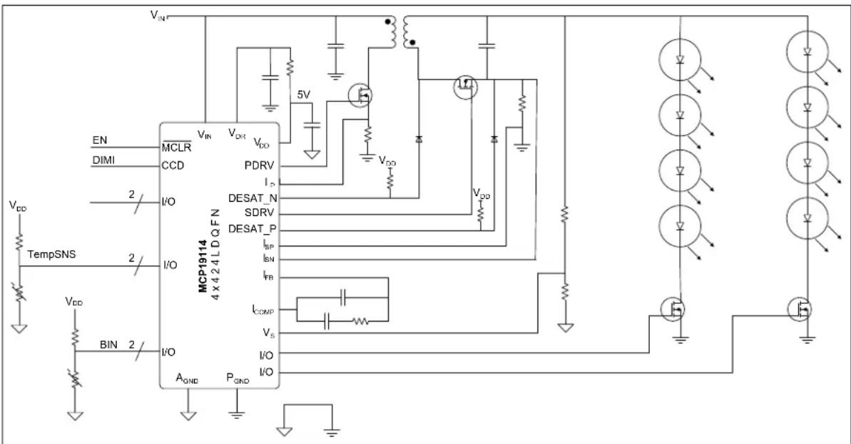
text_image
VDD TempSNS VDD BIN 2 MCLR CCD I/O I/O MCP1914 4 x 4 2 4 L D Q F N VIN VIN VDR VDD PDRV I2 DESAT_N SDRV DESAT_P ISP ISN IFB ICOMP VS I/O A GND PGND 5V VDD VDD VDDFIGURE 1-1: Typical MCP19114 Flyback Application – Two String LED Driver.
1.3 WHAT IS THE MCP19114 - FLYBACK STAND-ALONE EVALUATION BOARD?
The MCP19114 - Flyback Stand-Alone Evaluation Board is intended to demonstrate how the MCP19114 device operates in a synchronous flyback topology. It is configured to regulate load current and is also well-suited to drive LED loads. Nearly all operational and control system parameters are programmable by utilizing the integrated PIC Microcontroller core.
The MCP19114 comes preprogrammed with firmware designed to operate with the GUI interface. MPLABX IDE software can be used to download user defined firmware, and thus tailoring it to their specific application. The evaluation board contains headers for In-Circuit Serial Programming ^™ (ICSP) as well as I ^2 C communication.
Several test points have been designed into the printed circuit board for easy access and development purposes. The MCP19114 - Flyback Stand-Alone Evaluation Board is also intended to demonstrate an optimized Printed Circuit Board (PCB) layout that minimizes parasitics while increasing efficiency and power density. Proper PCB layout is critical to achieve optimum MCP19114 operation as well as power train efficiency and noise minimization. MPLABX IDE, MCP19114 - Flyback Stand-Alone GUI and MCP19114 - Flyback Stand-Alone Firmware are available for download from Microchip's web site. See Chapter 3. "Graphical User Interface (GUI)" for details.
1.4 MCP19114 - FLYBACK STAND-ALONE EVALUATION BOARD KIT CONTENTS
The MCP19114 - Flyback Stand-Alone Evaluation Board includes the following items:
- MCP19114 - Flyback Stand-Alone Evaluation Board (ADM00578)
- Important Information Sheet
Chapter 2. Installation and Operation
2.1 INTRODUCTION
2.1.1 MCP19114 - Flyback Stand-Alone Evaluation Board Features
The MCP19114 is a digitally-enhanced, power analog, synchronous low-side pulse-width modulation (PWM) controller. The graphical user interface was developed to assist users in easily configuring the MCP19114 and evaluating it in their target application.
The MCP19114 - Flyback Stand-Alone Evaluation Board is designed to operate from a single supply (nominal 8V to 14V, 24V maximum). The primary side MOSFET has a maximum V_DS rating of 100V. Users should be cautious that this 100V rating is not exceeded when determining input and output conditions for their application. The coupled inductor has a 2:1 ratio. The secondary MOSFET has a 200V maximum V_DS rating.
The default configuration provides the gate drive supply ( V_DR ) with 10V. Adequate ceramic and bulk capacitors are supplied on the input to reduce the root mean square (RMS) ripple current and lessen input voltage deviation caused by load transients. Ceramic capacitors are also provided on the output to reduce voltage ripple and provide energy to the output while the primary side is being re-energized.
The MCP19114 - Flyback Stand-Alone Evaluation Board is fully assembled, programmed and tested to evaluate and demonstrate the MCP19114 operating performance. Users will need to download and install the MCP19114 - Flyback Stand-Alone GUI from the Microchip website and become familiar with its operation before powering the MCP19114 - Flyback Stand-Alone Evaluation Board.
2.2 GETTING STARTED
2.2.1 Configuration Requirements
To power up and run the MCP19114 - Flyback Stand-Alone Evaluation Board, the following is required:
• MCP19114 - Flyback Stand-Alone GUI
• MCP19114 - Flyback Stand-Alone Evaluation Board
- PICkit Serial Analyzer
Note: The factory-loaded firmware REQUIRES the use of the provided GUI to function. Without the GUI, the evaluation board will not operate.
2.2.2 Installing the MCP19114 - Flyback Stand-Alone GUI
Follow the steps to download and install the MCP19114 - Flyback Stand-Alone GUI:
- Download the MCP19114 - Flyback Stand-Alone GUI software package from the Microchip web site.
- Extract the content of the archive files on the computer.
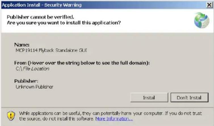
- Double-click the setup.exe file to start software installation. Press the Install button in the Application Install window (Figure 2-1). Once the installation completes, the GUI window will open (see Figure 3-1 in Chapter 2. "Installation and Operation").
text_image
Application Install - Security Warning Publisher cannot be verified. Are you sure you want to install this application? Name: MCP19114 Flyback Standalone GUI From (Hover over the string below to see the full domain): C:\File Location Publisher: Unknown Publisher Install Don't Install While applications can be useful, they can potentially harm your computer. If you do not trust the source, do not install this software. More information...FIGURE 2-1: MCP19114 - Flyback Stand-Alone GUI Installation Window.
2.2.3 Power Input and Output Connection
The MCP19114 comes programmed with generic firmware compatible with the standalone GUI. It is up to the user to modify or create new firmware dedicated to their stand-alone application if different functionality is required.
Note: If the default firmware is modified, the GUI may no longer be compatible with the MCP19114 - Flyback Stand-Alone Evaluation Board.
2.2.3.1 APPLYING POWER
Use the V_IN and GND Test Points as shown below. Nominal V_IN is +8V to +14V with the Positive terminal (Red) connected to V_IN and the Negative terminal (Black) connected to GND.

text_image
VOUT GND GND VIN S4Z R13 S4I R12 C2 C9 L5H1 L5H2 VOUT VOUT Q2 R6 OSDRU TPI DSAT_P DSAT_N MicroCHIP ADM00578 CE J3 MCP19114 Flyback Evaluation Board C10 P D10 ISPO C10 R17 R16 R15 R14 R13 R12 R11 R10 R9 R8 R7 R6 R5 R4 R3 R2 R19-100 C15 B1-R22 C16 C17 C18 C19 C20 C21 C22 C23 C24 C25 C26 C27 C28 C29 C30 C31 C32 C33 C34 C35 C36 C37 C38 C39 C40 C41 C42 C43 C44 C45 C46 C47 C48 C49 C50 C51 C52 C53 C54 C55 C56 C57 C58 C59 C60FIGURE 2-2: Applying Power to the Board.
CAUTION
The Primary side MOSFET is Rated to 100V. The transformer turns ratio is 1:2. Do Not exceed the 100V MOSFET Rating. Primary MOSFET (OFF) V_DS = 0.5 × V_OUT + V_IN .
2.2.4 Preprogrammed MCP19114 - Flyback Stand-Alone Evaluation Board
The MCP19114 - Flyback Stand-Alone Evaluation Board comes with preprogrammed firmware installed to operate with the GUI. To reprogram the device, the following tools are required:
- MPLAB X IDE (version 1.5 or later)
- MPLAB ^ XC8 C Compiler (v1.3 or later)
• MCP19114 - Flyback Stand-Alone Firmware
• MCP19114 - Flyback Stand-Alone Evaluation Board - PICkit™ 3 In-Circuit Debugger/Programmer
Follow the steps to install all necessary software and start reprogramming the MCP19114 device:
- If MPLAB X is already installed, go to Step 2. If not, download MPLAB X from: www.microchip.com/mplabx, and follow the MPLAB X installation instructions.
- If an XC8 compatible C-compiler, or an equivalent, is already installed in MPLAB X, go to Step 3. If not, you can download a free version of Microchip's XC8 from: www.microchip.com/mplabxc. The XC8 user guide, installation instructions, and download links are available on this page.
- Download the MCP19114 - Flyback Stand-Alone Firmware (*.zip) from www.microchip.com/mcp19114 under "Documentation & Software/Software".
- Unzip the MCP19114 - Flyback Stand-Alone Firmware archive. Place the MCP19114 project folder in the desired folder location.
Note: When installed, MPLAB X IDE automatically creates a project folder. In Windows ^® , this folder can typically be found under drive\Users\user_name\MPLABXProjects.
- Power up the MCP19114 - Flyback Stand-Alone Evaluation Board.
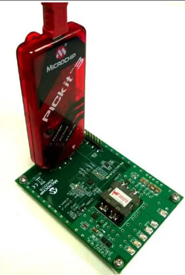
- Connect the PICkit 3 In-Circuit Debugger to the MCP19114 - Flyback Stand-Alone Evaluation Board via the 6-pin connector J3, as seen in Figure 2-3 (for more information about PICkit 3 In-Circuit Debugger refer to the "PICkit™ 3 In-Circuit Debugger/Programmer User's Guide For MPLAB® X IDE" - DS52116).
natural_image
Green printed circuit board with a red microchip labeled 'PICKIT' and a small electronic component (no readable text or symbols on the board itself)FIGURE 2-3: PICkit 3 In-Circuit Debugger/Programmer Connected to the MCP19114 - Flyback Stand-Alone Evaluation Board.
- Open MPLAB X IDE to load MCP19114 - Flyback Stand-Alone Firmware. From the File menu select Open Project (Figure 2-4).

text_image
MPLAB X IDE v 1.85 File Edit View Navigate Source Refactor Run Debug Team Tools Window Help New Project... Ctrl+Shift+N New File... Ctrl+N Open Project... Ctrl+Shift+O Open Recent Project Import Open Team Project... Close Project Close All Projects Open File... Open Recent File Project Group Start PageFIGURE 2-4: Opening Project in MPLAB X IDE.
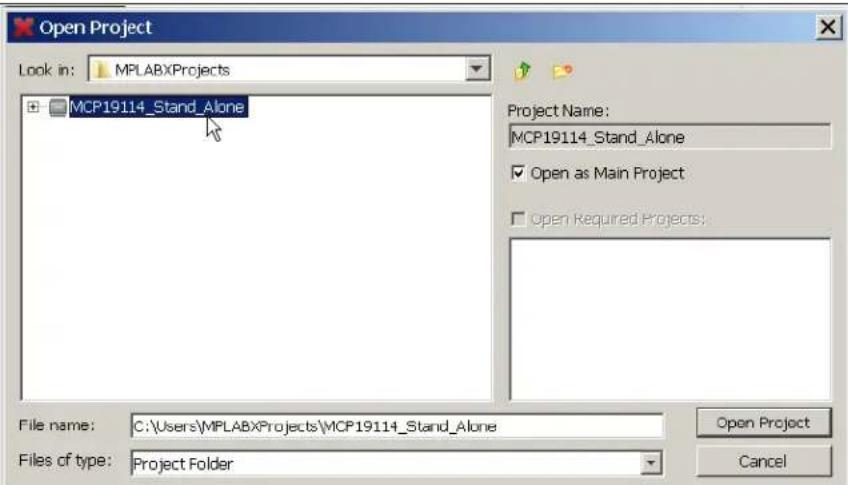
- Browse for the location of the extracted firmware. Select the MCP19114_Stand_Alone from the list, then check the Open as Main Project option. Press the Open Project button to complete loading the file.
text_image
Open Project Look in: MPLABXProjects MCP19114_Stand_Alone Project Name: MCP19114_Stand_Alone ✓ Open as Main Project □ open Required Projects: File name: C:\Users\MPLABXProjects\MCP19114_Stand_Alone Files of type: Project Folder Open Project CancelFIGURE 2-5: Loading Firmware into MPLAB X IDE.
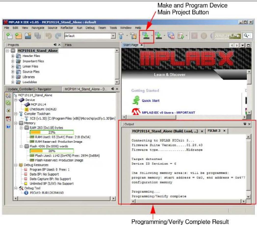
- Once the project is opened, click Make and Program Device Main Project button on the tool bar to program the device. Wait until the program process is complete.
text_image
Make and Program Device Main Project Button MPLABX Learn & Discover Gotting Started Quick Start MPLAB IDE v0 Users - IMPORTANT Output MCP19114_Stand_Aline (Build, Load, ...) × PICkit 3 × Connecting to MPLAB PICkit 3... Firmware Suite Version.....01.28.40 Firmware type......Midrange Target detected Device ID Revision = G The following memory area(s) will be programmed: program memory: start address = 0x0, end address = 0x4?? configuration memory Programming... Programming/Verify complete Update_Controller() - Navigator | MCP19114_Stand_Aline - D... MCP19114_Stand_Aline Device MCP 19114 Checksum: 0xD62D Compiler Toolchan XC8 (v1.30) [C:\Program Files (x85)\Microchip\xc8\v1.30\bin] Memory RAM 283 (0x11B) bytes 23% RAM Used: 65 (0x41) Free: 218 (0xDA) RAM Reserved: Production Image Flash 4096 (0x1000) words 20% Flash Used: 1142 (0x475) Free: 2954 (0x88A) Flash Reserved: Production Image Debug Resources Program BP Used: 0 Free: 1 Data BP: No Support Data Capture BP: No Support Unlimited BP (S/W): No Support Debug Tool PICkit3: BLR1202S4150 Programming/Verify Complete ResultFIGURE 2-6: Selecting and Executing the Make and Program Device Main Project in MPLAB X IDE.
NOTES:
Chapter 3. Graphical User Interface (GUI)
3.1 INTRODUCTION
The MCP19114 - Flyback Stand-Alone GUI requires a Windows® XP/7/8 operating system, a USB port and a minimum screen resolution of 1024 x 768. To run the software, follow the steps described in this section.
- Apply an input voltage in the normal operating range (8V to 14V) at the V _IN and Ground test points.
- Connect the PICkit Serial Analyzer to the PC via USB port and then connect the analyzer to the Control Board via the 6-pin serial connector J5 (Figure 3-1).

text_image
MICROCHIP PICkit™ Serial Analyzer Power Target Buy EP19H11 Fitback Evaluation Board MICROCHIP 10000578 CEFIGURE 3-1: PICkit Serial Analyzer Connection to the Board.
- To start the GUI, select Start > All Programs > Microchip Technology Inc. > MCP19114 Flyback Standalone GUI. The interface detects the MCP19114 device automatically and is ready for use (see Figure 3-2).

text_image
Microchip Technology MCP19114 FLYBACK STANDALONE GUI System Parameters Drivers Enable/Disable ON OFF Operating Mode Quasi-resonant Fixed Frequency Synchronous Operation Parameters Switching Frequency 100 kHz Max Duty Cycle 85 % Output Current 200 mA Current Sense Resistor 200 mΩ Protection Enable Input OVLO 13 V Enable Input UVLO 8 V Enable Output CVUQ 40 V Switches Enable/Disable Switch 1 Switch 2 Test Pin GRS (Output of Desar Comparator) Advanced Register Update Enable Edit LEB PDRV Deadline SDRV Deadline 200x1 120 na delay 120 na delay Input Current Offset Slope Compensation 0mV 29 Address Data Bank Select Register 1 0x 0 x n 0.1 7/3 Register 2 0x 0 x n 0.1 7/3 Register 3 0x 0 x n 0.1 7/3 Register 4 0x 0 x n 0.1 7/3 Register Online Adjust Address Data Bank 0/1 0x 0 x 0 Bank 2/3 Write Read Control Buttons Initialize PICKit Serial Check for Evaluation Board Update Turn Off Drivers Operating Status Box PICit Serial Correctly configured for i2C mode MCP19114 Evaluation Board Detected MCP19114 Evaluation Board Update Successful All Drivers Turned Off MICROCHIPFIGURE 3-2: MCP19114 - Flyback Stand-Alone GUI - Initial Screen.
3.2 CONFIGURING PARAMETERS
As depicted in Figure 3-2, the MCP19114 - Flyback Stand-Alone GUI is divided into four parts:
- System Parameters
- Register Online Adjust
- Control Buttons
- Operating Status Box
3.2.1 System Parameters
3.2.1.1 DRIVERS ENABLE/DISABLE
The Drivers Enable/Disable section defaults to OFF when starting the MCP19114 - Flyback Stand-Alone GUI. When this is set to ON, all other adjustable parameters become active for adjustment. When OFF is selected, the GUI will turn off the drivers and make all of the parameters unavailable for change so they cannot be altered.
3.2.1.2 PARAMETERS
This section controls the Switching Frequency, Maximum Duty Cycle, Output Current and Current Sense Resistor parameters. The switching frequency is user programmable in Fixed Frequency mode over the range of 60 kHz to 1 MHz. Switching Frequency can be adjusted in 10 kHz intervals. The maximum duty cycle is programmable from 0 to 100%.
CAUTION
Increasing switching frequency results in increased switching losses in the MOSFETs. It is the user's responsibility to ensure MOSFETs are operated within their safe operating range.
Users can adjust the Output Current over a range of 0 to 500 mA. The Current Sense Resistor (R6) value on the MCP19114 - Flyback Stand-Alone Evaluation Board is 200 mΩ. Both of these values are used to calculate the set point value written to the VREFCON register. DO NOT raise the resistor value in the GUI without changing the resistor on the evaluation board to match. Failure to do so could result in damage to the evaluation board.
Note: Attempting to write a value larger than 0xFF to VREFCON is prohibited by the GUI.
3.2.1.3 OPERATING MODE
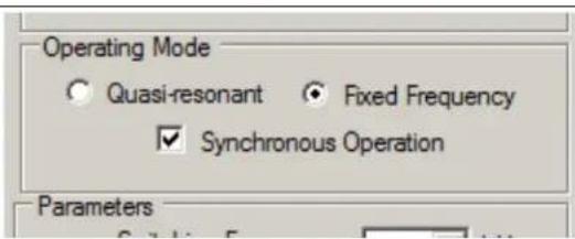
This section controls whether the Flyback converter is operated in Fixed-Frequency, Quasi-Resonant, Synchronous or Asynchronous Modes. When running in Fixed Frequency mode, the switching frequency parameters are adjustable. The third button is for Synchronous Operation. When the EN ON button is selected on the GUI, the Synchronous Operation box is automatically selected by default, putting the evaluation board in Synchronous mode. If the Synchronous Operation box is unchecked, the evaluation board is set to Asynchronous operation which disables the secondary driver (SDRV).
text_image
Operating Mode ○ Quasi-resonant ○ Fixed Frequency ✓ Synchronous Operation ParametersFIGURE 3-3: Operating Mode Options.
3.2.1.4 PROTECTION
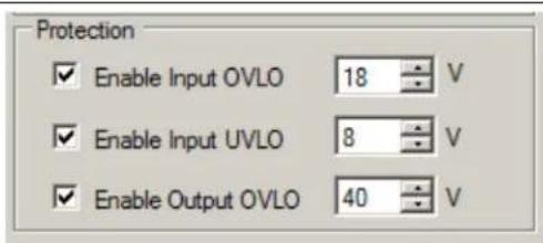
The Protection control allows the user to set levels for the three adjustable protection features. Input Voltage Under Voltage Lockout (VIUVLO), Input Voltage Overvoltage Lockout (VINOVLO) and Output Voltage Overvoltage (OV) can all be configured in this section of the GUI.
text_image
Protection ✓ Enable Input OVLO 18 V ✓ Enable Input UVLO 8 V ✓ Enable Output OVLO 40 VFIGURE 3-4: Protection Options.
The VINUVLO and VINOVLO Protection parameters are configurable per their specified ranges. The specified range for VINUVLO is 4V to 20V. The default VINUVLO setting in the GUI is 8V. The specified VINOVLO range is 9V to 24V. The default VINOVLO setting in the GUI is 18V. The Output OV has a configurable range between 0V and 60V. The default OV setting in the GUI is 40V.
The LED (D2) on the evaluation board is used to indicate various fault conditions. The firmware will flash this LED to indicate each of the following fault conditions:
• VIN UVLO FAULT: Short Flash Routine
• VIN OVLO FAULT: Long Flash Routine
• OUTPUT OV FAULT: Short/Long Flash Routine
WARNING
Use caution when changing from these default settings to ensure that damage will not occur. The VINUVLO, VINOVLO and Output OV controls adjust the VINUVLO, VINOVLO and OVREFCON registers, respectively.
3.2.1.5 TEST PIN
This section of the GUI has a drop-down menu that allows users to select and connect test signals to GPIO GPA0. These signals are accessible at the test point labeled TEST. The Test Pin can be configured to output several analog or digital parameters. See Figure 3-5 for the list of signals.

text_image
Test Pin QRS (Output of Desat Comparator) QRS (Output of Desat Comparator) PWM_L (PWM output after monostable) PWM (Oscillator Output from the Micro-controller) TMR2EQ (When TMR2 equals PR2) OV (Over Voltage Comparator Output) VIN/15.533 VREF (DAC Reference voltage setting current regulation level) OV_REF (Reference for over voltage comparator) VBGR (Bandgap Reference) Vs (Voltage proportional to VOUT) EA_SC (Error amp after slope compensation output) A2 (Secondary Current sense amplifier output) IP_ADJ (IP after Pedestal and offset adjust) IP_OFF (IP offset reference) VDR/n (VDR/n analog driver measurement) TEMP_SNS (Analog voltage representing internal temperature) GPA0/AN0 GPA1/AN1 GPA2/AN2 GPA3/AN3 GPB1/AN4FIGURE 3-5: Test Pin Options.
3.2.1.6 SWITCHES ENABLE/DISABLE
There are two general purpose MOSFET low-side series switches located on MCP19114 - Flyback Stand-Alone Evaluation Board (LSW1 and LSW2). The control boxes in the Switches Enable/Disable section of the GUI allow the user to turn these switches ON (checked) and OFF (unchecked).
3.2.1.7 ADVANCED REGISTER UPDATE
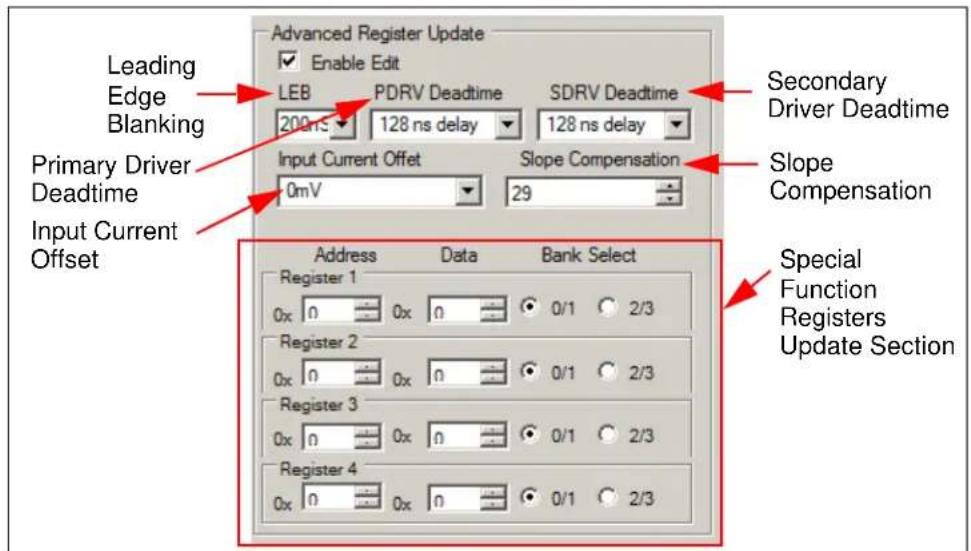
This section of GUI gives the user more options to configure and operate the MCP19114 - Flyback Stand-Alone Evaluation Board. The adjustable parameters include Leading Edge Blanking (LEB), Primary Driver (PDRV) Deadtime, Secondary Driver (SDRV) Deadtime, Input Current Offset and Slope Compensation. In addition, this section allows users to update up to four Special Function Registers (SFR) at the same time. For more information on Special Function Registers, refer to the MCP19114/5 Data Sheet – “Digitally Enhanced Power Analog Synchronous Low-Side PWM Controller” (DS20005281).
text_image
Advanced Register Update Enable Edit LEB PDRV Deadtime SDRV Deadtime 200 ns 128 ns delay 128 ns delay Input Current Offset Slope Compensation 0mV 29 Primary Driver Deadtime Input Current Offset Address Data Bank Select Register 1 0x 0x 0/1 2/3 Register 2 0x 0x 0/1 2/3 Register 3 0x 0x 0/1 2/3 Register 4 0x 0x 0/1 2/3 Secondary Driver Deadtime Slope Compensation Special Function Registers Update SectionFIGURE 3-6: Advanced Register Update Options.
3.2.2 Register Online Adjust
The Register Online Adjust section of the GUI allows the user to have direct control of register values at any time when operating the MCP19114. The device data sheet contains information on register address locations and content. Reads and writes are done in hexadecimal format. Users must select the proper bank, which is especially important when executing a write. It is good practice to always execute an address read before a write, to check for expected results. This may help prevent an unintended write to an improper address or bank. Please note that the Update button will not update this section.

text_image
Register Online Adjust Address Data Bank 0/1 0x 0 0x 0 Bank 2/3 Write ReadFIGURE 3-7: Register Online Adjust Options.
3.2.3 Control Buttons
The two buttons on the left are user selectable self-test options. The Initialize PICkit Serial button checks communication between your computer and PICkit Serial Analyzer. The Check for Evaluation Board can be selected by the user to manually ask software to detect the evaluation board.
The Update button will apply the configuration settings made in Operating Mode, Parameters, Protection, Switches Enable/Disable, Advanced Register Update and will turn on the output drivers. It will not update the Register Online Adjust section.
The Turn Off Drivers button is a Master Stop that shuts off the output drivers. Pressing this button will disable both Primary and Secondary drivers.

text_image
Initialize PICKit Serial Check for Evaluation Board Update Turn Off Drivers PICkit Serial Capacity configured for I2C modeFIGURE 3-8: Control Buttons.
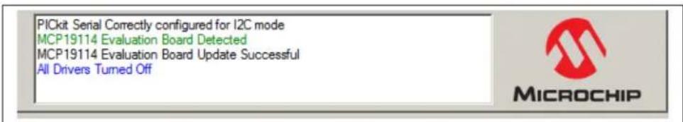
3.2.4 Operating Status Box
This box provides messages to the user and operating status. Examples of status messages are shown in Figure 3-9.
text_image
PICkit Serial Correctly configured for I2C mode MCP19114 Evaluation Board Detected MCP19114 Evaluation Board Update Successful All Drivers Turned Off MICROCHIPFIGURE 3-9: Operating Status Box.
Appendix A. Schematic and Layouts
A.1 INTRODUCTION
This appendix contains the following schematics and layouts for the MCP19114 - Flyback Stand-Alone Evaluation Board:
- Board – Schematic
- Board – Top Layer
- Board – Top Copper
- Board – Mid Layer 1
- Board – Mid Layer 2
- Board – Bottom Copper
- Board – Bottom Layer
A.2 BOARD - SCHEMATIC

text_image
Electrical schematic diagram with labeled components including resistors, capacitors, inductors, and electronic circuitsA.3 BOARD - TOP LAYER
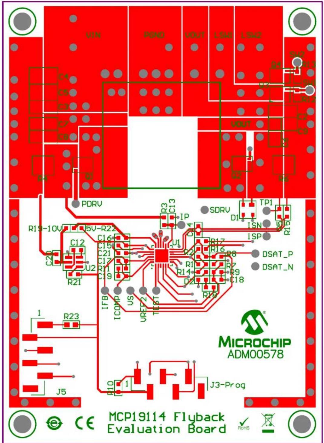
text_image
VIN P6NO VOUT LSM1 LSM2 S42 R13 C1 C5 C3 C7 C8 D1 D2 D3 D4 D5 D6 D7 D8 D9 D10 C2 C12 C16 C15 C21 C17 U2 R11 C19 R21 R3 C13 IP SDRV D1 TP1 ISN R15 R19-10V 5V-R22 C2 C16 C15 C21 C17 U2 R14 R17 R16 R8 R7 R9 C18 IFB ICOMP US UREF2 TEST R18 R23 J5 J3-Prog MICROCHIP ADM00578 e CE MCP19114 Flyback Evaluation Board ✓ RoHSA.4 BOARD - TOP COPPER
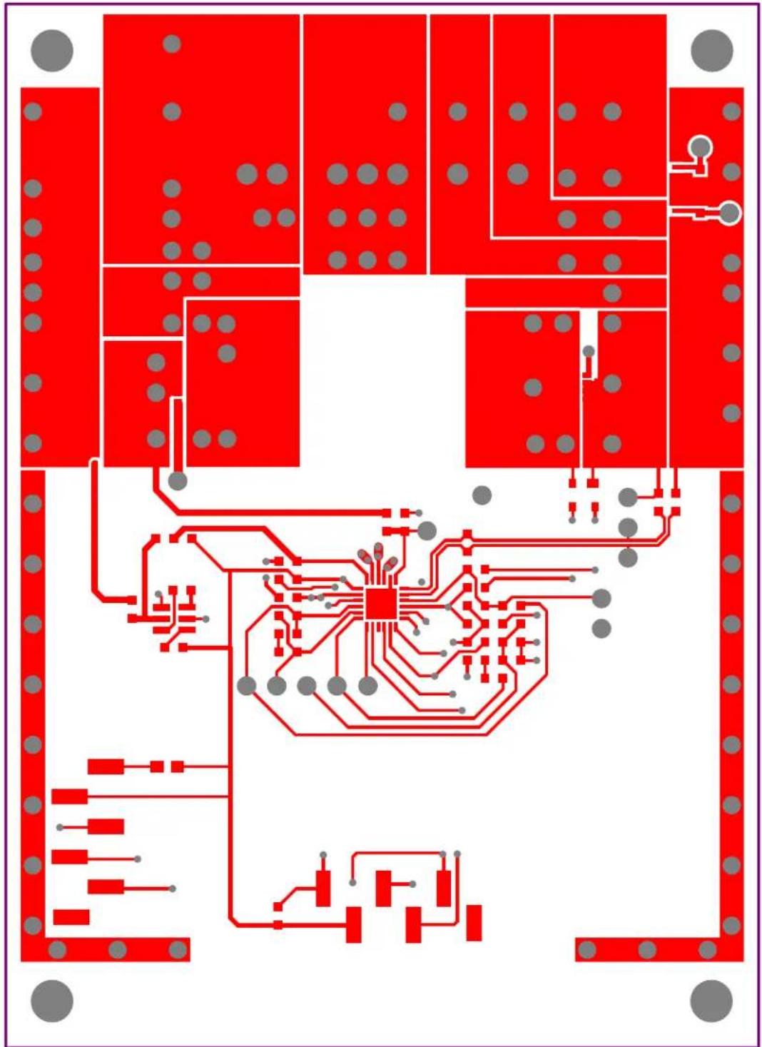
natural_image
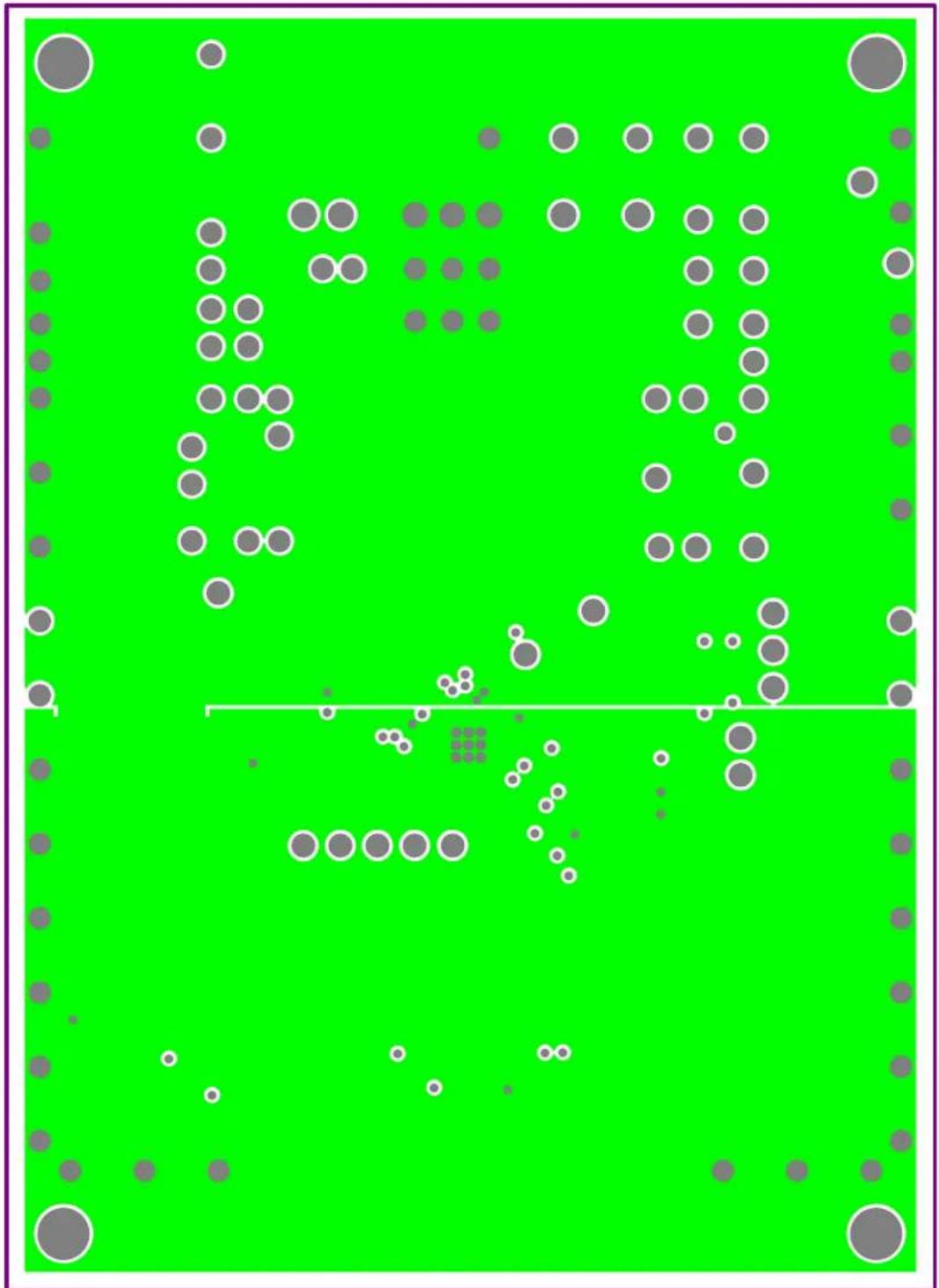
Pure electrical circuit lines without any symbolsA.5 BOARD - MID LAYER 1
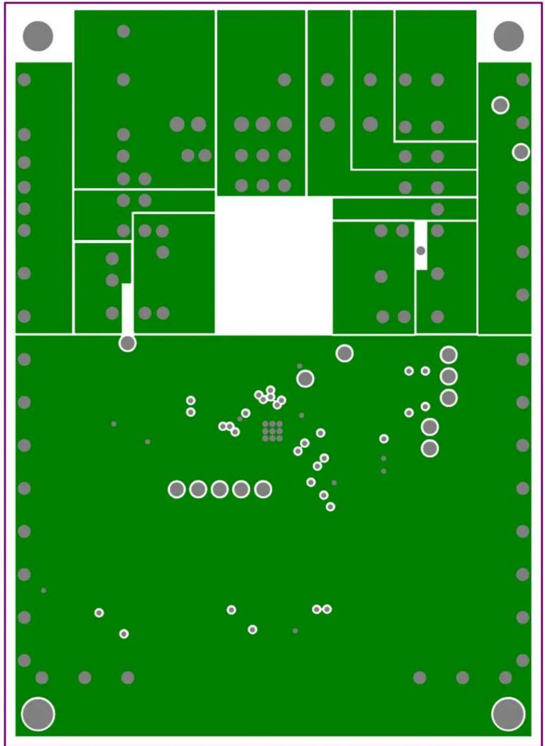
bubble
| Point Type | Color | Size | |------------|--------|------| | White Circle | Green | 100 | | White Circle | Grey | 5 | | White Circle | Grey | 20 | | White Circle | Grey | 30 | | White Circle | Grey | 40 | | White Circle | Grey | 50 | | White Circle | Grey | 60 | | White Circle | Grey | 70 | | White Circle | Grey | 80 | | White Circle | Grey | 90 | | White Circle | Grey | 100 | | White Circle | Grey | 110 | | White Circle | Grey | 120 | | White Circle | Grey | 130 | | White Circle | Grey | 140 | | White Circle | Grey | 150 | | White Circle | Grey | 160 | | White Circle | Grey | 170 | | White Circle | Grey | 180 | | White Circle | Grey | 190 | | White Circle | Grey | 200 | | White Circle | Grey | 210 | | White Circle | Grey | 220 | | White Circle | Grey | 230 | | White Circle | Grey | 240 | | White Circle | Grey | 250 | | White Circle | Grey | 260 | | White Circle | Grey | 270 | | White Circle | Grey | 280 | | White Circle | Grey | 290 | | White Circle | Grey | 300 | | White Circle | Grey | 310 | | White Circle | Grey | 320 | | White Circle | Grey | 330 | | White Circle | Grey | 340 | | White Circle | Grey | 350 | | White Circle | Grey | 360 | | White Circle | Grey | 370 | | White Circle | Grey | 380 | | White Circle | Grey | 390 | | White Circle | Grey | 400 | | White Circle | Grey | 410 | | White Circle | Grey | 420 | | White Circle | Grey | 430 | | White Circle | Grey | 440 | | White Circle | Grey | 450 | | White Circle | Grey | 460 | | White Circle | Grey | 470 | | White Circle | Grey | 480 | | White Circle | Grey | 490 | | White Circle | Grey | 500 | | White Circle | Grey | 510 | | White Circle | Grey | 520 | | White Circle | Grey | 530 | | White Circle | Grey | 540 | | White Circle | Grey | 550 | | White Circle | Grey | 560 | | White Circle | Grey | 570 | | White Circle | Grey | 580 | | White Circle | Grey | 590 | | White Circle | Grey | 600 | | White Circle | Grey | 610 | | White Circle | Grey | 620 | | White Circle | Grey | 630 | | White Circle | Grey | 640 | | White Circle | Grey | 650 | | White Circle | Grey | 660 | | White Circle | Grey | 670 | | White Circle | Grey | 680 | | White Circle | Grey | 690 | | White Circle | Grey | 700 | | White Circle | Grey | 710 | | White Circle | Grey | 720 | | White Circle | Grey | 730 | | White Circle | Grey | 740 | | White Circle | Grey | 750 | | White Circle | Grey | 760 | | White Circle | Grey | 770 | | White Circle | Grey | 780 | | White Circle | Grey | 790 | | White Circle | Grey | 800 | | White Circle | Grey | 810 | | White Circle | Grey | 820 | | White Circle | Grey | 830 | | White Circle | Grey | 840 | | White Circle | Grey | 850 | | White Circle | Grey | 860 | | White Circle | Grey | 870 | | White Circle | Grey | 880 | | White Circle | Grey | 890 | | White Circle | Grey | 900 | | White Circle | Grey | 910 | | White Circle | Grey | 920 | | White Circle | Grey | 930 | | White Circle | Grey | 940 | | White Circle | Grey | 950 | | White Circle | Grey | 960 | | White Circle | Grey | 970 | | White Circle | Grey | 980 | | White Circle | Grey | 990 | | White Circle | Grey | - | | Black Square (Bottom) - Black Square (Top) - Black Square (Bottom) - Black Square (Top) - Black Square (Bottom) - Black Square (Bottom) - Black Square (Bottom) - Black Square (Bottom) - Black Square (Bottom) - Black Square (Bottom) - Black Square (Bottom) - Black Square (Bottom) - Black Square (Bottom) - Black Square (Bottom) - Black Square (Bottom) - Black Square (Bottom) - Black Square (Bottom) - Black Square (Bottom) - Black Square (Bottom) - Black Square (Bottom) - Black Square (Bottom) - BlackSquare (Bottom) - Black Square (Bottom) - Black Square (Bottom) - Black Square (Bottom) - Black Square (Bottom) - Black Square (Bottom) - Black Square (Bottom) - Black Square (Bottom) - Black Square (Bottom) - Black Square (Bottom) - Black Square (Bottom) - Black Square (Bottom) - Black Square (Bottom) - Black Square (Bottom) - Black Square (Bottom) - Black Square (Bottom) - Black Square (Bottom) = Black Square / Black Square / Black Square / Black Square / Black Square / Black Square / Black Square / Black Square / Black Square / Black Square / Black Square / Black Square / Black Square / Black Square / Black Square / Black Square / Black Square / Black Square / Black Square / Black Square / Black Square / Black Square / Black Square / Black Square / Black Square / Black Square / Black Square / Black Square / Black Square / Black Square / Black Square / Black Square / Black Square / Black Square /A.6 BOARD - MID LAYER 2
A.7 BOARD - BOTTOM COPPER

natural_image
Pure electrical circuit lines without any symbols or text, showing components in blue and gray with no readable text or labels.A.8 BOARD - BOTTOM LAYER

text_image
C1 C10 C11 D3 04-10290-R1Appendix B. Bill of Materials (BOM)
TABLE 2-1: BILL OF MATERIALS (BOM)
| Qty. | Reference Description Manufacturer Part Number | |||
| 4 4 | 40 screw Machine screw 4-40 1/4 B&F | TM Fasteners Supply | PMSSS 4400025 PH | |
| 4 | 4 - 4 0 standoff 1/4 | Hex standoff 4-40 aluminum1/4 | Keystone Electronics | 2201 |
| 4 C1 | C2, C9, C10 | DO NOT POPULATE | — | — |
| 1 | C3 | Cap.ceramic1 μF,100V,X7R,Auto1206 | TDK Corporation | CGA5L2X7R2A105M/SOFT |
| 2 | C4, C5 | Cap.ceramic10 μF,50V,X7R,Auto1210 | Taiyo Yuden Co., Ltd. | UMK325AB7106MM-T |
| 2 | C6, C11 | Cap.ceramic2.2 μF,50V,X7R,Auto1206 | TDK Corporation | CGA5L3X7R1H225K |
| 1 | C7 | Cap.ceramic4.7 μF,50V,X7R,Auto1206 | TDK Corporation | C3216X7R1H475K160AC |
| 1 | C8 | Cap.ceramic3.3 μF,50V,X7R,Auto1206 | TDK Corporation | C3216X7R1H335K160AC |
| 2 | C12, C20 | Cap.ceramic 1 μF,25V,X7R,Auto 0603 | TDK Corporation | CGA3E1X7R1E105K |
| 2 | C13, C14 | DO NOT POPULATE | — | — |
| 2 | C15, C16 | Cap.ceramic4.7 μF,16V,X5R,Auto0603 | TDK Corporation | C1608X5R1C475K |
| 1 | C17 | Cap. ceramic 220 pF, 50V, COG 0603 | Murata Electronics® | GCM1885C1H221JA16D |
| 1 | C18 | Cap. ceramic 1 nF, 50V, COG 0603 | Murata Electronics® | GCM1885C1H102JA16D |
| 1 | C19 | Cap. ceramic 10 nF 50V 10% X7R 0603 | TDK Corporation | C1608X7R1H103K080AA |
| 1 | C21 | Cap.ceramic0.1 μF,50V,X7R,Auto0603 | TDK Corporation | CGA3E2X7R1H104K |
| 1 | D1A, D1B | Diode SW DBL 200V 225 mA SOT143B | NXP Semiconductor | BAV23, 215" |
| 1 D2 | LED, super red, clear 0603 L | te-On ® Technology Corporation | LTST-C190KRKT | |
| 1 D3 | TVS diode 90 VWM 146 VC SMA Uni-Dir Littlefuse ® | SMAJ90A | ||
| 2 | J3,J5 | Header,6 Pos.,2.54 mm,SMT,vert.,gold | Samtec, Inc. | TSM-106-01-L-SV |
| 1 PCB | Printed Circuit Board - MCP19114 - Flyback Stand-Alone Evaluation Board | — | 04-10290 | |
| 3 | Q1, Q3, Q4 | N-Channel MOSFET, 100V | Vishay Intertechnology, Inc. | SIS890DN-T1-GE3 |
| 1 Q2 | MOSFET N-Ch. 200V 15.2A 8TSDSON | Infineon Technologies AG | BSZ900N20NS3 G | |
| 2 | R1, R2 | Res. 3.92 kΩ 1/10th Watt, 1% 0603 SMD | Panasonic® - ECG | ERJ-3EKF3921V |
| 6 R3 | R5, R15, R16, R17, R21 | Res. 0.0Ω 1/10W 0603 SMD | Panasonic - ECG | ERJ-3GEY0R00V |
| 1 | R4 | Res. 50 mΩ 1 Watt, 1% 0612 SMD | Susumu Co., LTD. | PRL1632-R050-F-T1 |
| 1 | R6 | Res. 200 mΩ 1 Watt, 1% 0612 SMD | Rohm Semiconductor | LTR18EZPFLR200 |
| 1 | R7 | Res. 100 kΩ 1/10th Watt, 1% 0603 SMD | Panasonic - ECG | ERJ-3EKF1003V |
| 1 | R8 | DO NOT POPULATE | — | — |
| 1 | R9 | Res. 4.02 kΩ 1/10th Watt, 1% 0603 SMD | Panasonic - ECG | ERJ-3EKF4021V |
| Qty. | Reference | Description | Manufacturer | Part Number |
| 4 R | 10, R12,R13, R14 | Res. 10 kΩ 1/10th Watt, 1% 0603 SMD | Panasonic - ECG | ERJ-3EKF1002V |
| 1 | R11 | Res. 1.02 kΩ 1/10th Watt, 1% 0603 SMD | Panasonic - ECG | ERJ-3EKF1021V |
| 1 | R18 | Res. 475Ω 1/10th Watt, 1% 0603 SMD | Panasonic - ECG | ERJ-3EKF4750V |
| 1 | R19 | Res. 10.0Ω 1/10W 1% 0603 SMD | Panasonic - ECG | ERJ-3EKF10R0V |
| 1 | R22 | DO NOT POPULATE | — | — |
| 1 | R23 | Res. 10 kΩ 1/10th Watt, 1% 0603 SMD | Panasonic - ECG | ERJ-3EKF1002V |
| 1 T1 | Uni-Cuk Transformer 1:2 | Wurth ® Group 750341878 | ||
| 1 U1 | Digitally Enhanced PWM Power Analog Controller | Microchip Technology Inc. | MCP19114-E/MJ | |
| 1 U2 | Charge Pump, Doubler | Microchip Technology Inc. | TC1240A-E/CH | |
| 6 VIN, PGND,PGND1,VOUT,LSW1, LSW2 | Test point PC compact SMT | Keystone Electronics Corp. | 5016 | |
Note 1: The components listed in this Bill of Materials are representative of the PCB assembly. The released BOM used in manufacturing uses all RoHS-compliant components.
NOTES:
Worldwide Sales and Service
AMERICAS
Corporate Office
2355 West Chandler Blvd.
Chandler, AZ 85224-6199
Tel: 480-792-7200
Fax: 480-792-7277
Technical Support:
http://www.microchip.com/
support
Web Address:
www.microchip.com
Atlanta
Duluth, GA
Tel: 678-957-9614
Fax: 678-957-1455
Austin, TX
Tel: 512-257-3370
Boston
Westborough, MA
Tel: 774-760-0087
Fax: 774-760-0088
Chicago
Itasca, IL
Tel: 630-285-0071
Fax: 630-285-0075
Cleveland
Independence, OH
Tel: 216-447-0464
Fax: 216-447-0643
Dallas
Addison, TX
Tel: 972-818-7423
Fax: 972-818-2924
Detroit
Novi. MI
Tel: 248-848-4000
Houston, TX
Tel: 281-894-5983
Indianapolis
Noblesville, IN
Tel: 317-773-8323
Fax: 317-773-5453
Los Angeles
Mission Viejo, CA
Tel: 949-462-9523
Fax: 949-462-9608
New York, NY
Tel: 631-435-6000
San Jose, CA
Tel: 408-735-9110
Canada - Toronto
Tel: 905-673-0699
Fax: 905-673-6509
ASIA/PACIFIC
Asia Pacific Office
Suites 3707-14, 37th Floor
Tower 6. The Gateway
Harbour City, Kowloon
Hong Kong
Tel: 852-2401-1200
Fax: 852-2401-3431
Australia - Sydney
Tel: 61-2-9868-6733
Fax: 61-2-9868-6755
China - Beijing
Tel: 86-10-8569-7000
Fax: 86-10-8528-2104
China - Chengdu
Tel: 86-28-8665-5511
Fax: 86-28-8665-7889
China - Chongqing
Tel: 86-23-8980-9588
Fax: 86-23-8980-9500
China - Hangzhou
Tel: 86-571-8792-8115
Fax: 86-571-8792-8116
China - Hong Kong SAR
Tel: 852-2401-1200
Fax: 852-2401-3431
China - Nanjing
Tel: 86-25-8473-2460
Fax: 86-25-8473-2470
China - Qingdao
Tel: 86-532-8502-7355
Fax: 86-532-8502-7205
China - Shanghai
Tel: 86-21-5407-5533
Fax: 86-21-5407-5066
China - Shenyang
Tel: 86-24-2334-2829
Fax: 86-24-2334-2393
China - Shenzhen
Tel: 86-755-8864-2200
Fax: 86-755-8203-1760
China - Wuhan
Tel: 86-27-5980-5300
Fax: 86-27-5980-5118
China - Xian
Tel: 86-29-8833-7252
Fax: 86-29-8833-7256
China - Xiamen
Tel: 86-592-2388138
Fax: 86-592-2388130
China - Zhuhai
Tel: 86-756-3210040
Fax: 86-756-3210049
ASIA/PACIFIC
India - Bangalore
Tel: 91-80-3090-4444
Fax: 91-80-3090-4123
India - New Delhi
Tel: 91-11-4160-8631
Fax: 91-11-4160-8632
India - Pune
Tel: 91-20-3019-1500
Japan - Osaka
Tel: 81-6-6152-7160
Fax: 81-6-6152-9310
Japan - Tokyo
Tel: 81-3-6880-3770
Fax: 81-3-6880-3771
Korea - Daegu
Tel: 82-53-744-4301
Fax: 82-53-744-4302
Korea - Seoul
Tel: 82-2-554-7200
Fax: 82-2-558-5932 or
82-2-558-5934
Malaysia - Kuala Lumpur
Tel: 60-3-6201-9857
Fax: 60-3-6201-9859
Malaysia - Penang
Tel: 60-4-227-8870
Fax: 60-4-227-4068
Philippines - Manila
Tel: 63-2-634-9065
Fax: 63-2-634-9069
Singapore
Tel: 65-6334-8870
Fax: 65-6334-8850
Taiwan - Hsin Chu
Tel: 886-3-5778-366
Fax: 886-3-5770-955
Taiwan - Kaohsiung
Tel: 886-7-213-7830
Taiwan - Taipei
Tel: 886-2-2508-8600
Fax: 886-2-2508-0102
Thailand - Bangkok
Tel: 66-2-694-1351
Fax: 66-2-694-1350
EUROPE
Austria - Wels
Tel: 43-7242-2244-39
Fax: 43-7242-2244-393
Denmark - Copenhagen
Tel: 45-4450-2828
Fax: 45-4485-2829
France - Paris
Tel: 33-1-69-53-63-20
Fax: 33-1-69-30-90-79
Germany - Dusseldorf
Tel: 49-2129-3766400
Germany - Munich
Tel: 49-89-627-144-0
Fax: 49-89-627-144-44
Germany - Pforzheim
Tel: 49-7231-424750
Italy - Milan
Tel: 39-0331-742611
Fax: 39-0331-466781
Italy - Venice
Tel: 39-049-7625286
Netherlands - Drunen
Tel: 31-416-690399
Fax: 31-416-690340
Poland - Warsaw
Tel: 48-22-3325737
Spain - Madrid
Tel: 34-91-708-08-90
Fax: 34-91-708-08-91
Sweden - Stockholm
Tel: 46-8-5090-4654
UK - Wokingham
Tel: 44-118-921-5800
Fax: 44-118-921-5820
03/21/14