MEC1527 - Electronic component Microchip - Free user manual and instructions
Find the device manual for free MEC1527 Microchip in PDF.

User questions about MEC1527 Microchip
0 question about this device. Answer the ones you know or ask your own.
Ask a new question about this device
Download the instructions for your Electronic component in PDF format for free! Find your manual MEC1527 - Microchip and take your electronic device back in hand. On this page are published all the documents necessary for the use of your device. MEC1527 by Microchip.
USER MANUAL MEC1527 Microchip
CEC/MEC Family Peripheral Interface User's Guide
Note the following details of the code protection feature on Microchip devices:
• Microchip products meet the specification contained in their particular Microchip Data Sheet.
- Microchip believes that its family of products is one of the most secure families of its kind on the market today, when used in the intended manner and under normal conditions.
- There are dishonest and possibly illegal methods used to breach the code protection feature. All of these methods, to our knowledge, require using the Microchip products in a manner outside the operating specifications contained in Microchip's Data Sheets. Most likely, the person doing so is engaged in theft of intellectual property.
• Microchip is willing to work with the customer who is concerned about the integrity of their code.
- Neither Microchip nor any other semiconductor manufacturer can guarantee the security of their code. Code protection does not mean that we are guaranteeing the product as "unbreakable."
Code protection is constantly evolving. We at Microchip are committed to continuously improving the code protection features of our products. Attempts to break Microchip's code protection feature may be a violation of the Digital Millennium Copyright Act. If such acts allow unauthorized access to your software or other copyrighted work, you may have a right to sue for relief under that Act.
Information contained in this publication regarding device applications and the like is provided only for your convenience and may be superseded by updates. It is your responsibility to ensure that your application meets with your specifications. MICROCHIP MAKES NO REPRESENTATIONS OR WARRANTIES OF ANY KIND WHETHER EXPRESS OR IMPLIED, WRITTEN OR ORAL, STATUTORY OR OTHERWISE, RELATED TO THE INFORMATION, INCLUDING BUT NOT LIMITED TO ITS CONDITION, QUALITY, PERFORMANCE, MERCHANTABILITY OR FITNESS FOR PURPOSE. Microchip disclaims all liability arising from this information and its use. Use of Microchip devices in life support and/or safety applications is entirely at the buyer's risk, and the buyer agrees to defend, indemnify and hold harmless Microchip from any and all damages, claims, suits, or expenses resulting from such use. No licenses are conveyed, implicitly or otherwise, under any Microchip intellectual property rights unless otherwise stated.
Trademarks
The Microchip name and logo, the Microchip logo, AnyRate, AVR, AVR logo, AVR Freaks, BeaconThings, BitCloud, CryptoMemory, CryptoRF, dsPIC, FlashFlex, flexPWR, Heldo, JukeBlox, KEELoQ, KEELoo logo, Kleer, LANCheck, LINK MD, maXStylus, maXTouch, MediaLB, megaAVR, MOST, MOST logo, MPLAB, OptoLyzer, PIC, picoPower, PICSTART, PIC32 logo, Prochip Designer, QTouch, RightTouch, SAM-BA, SpyNIC, SST, SST Logo, SuperFlash, tinyAVR, UNI/O, and XMEGA are registered trademarks of Microchip Technology Incorporated in the U.S.A. and other countries.
ClockWorks, The Embedded Control Solutions Company, EtherSynch, Hyper Speed Control, HyperLight Load, IntelliMOS, mTouch, Precision Edge, and Quiet-Wire are registered trademarks of Microchip Technology Incorporated in the U.S.A.
Adjacent Key Suppression, AKS, Analog-for-the-Digital Age, Any Capacitor, AnyIn, AnyOut, BodyCom, chipKIT, chipKIT logo, CodeGuard, CryptoAuthentication, CryptoCompanion, CryptoController, dsPICDEM, dsPICDEM.net, Dynamic Average Matching, DAM, ECAN, EtherGREEN, In-Circuit Serial Programming, ICSP, Inter-Chip Connectivity, JitterBlocker, KleerNet, KleerNet logo, Mindi, MiWi, motorBench, MPASM, MPF, MPLAB Certified logo, MPLIB, MPLINK, MultiTRAK, NetDetach, Omniscient Code Generation, PICDEM, PICDEM.net, PICkit, PICtail, PureSilicon, QMatrix, RightTouch logo, REAL ICE, Ripple Blocker, SAM-ICE, Serial Quad I/O, SMART-I.S., SQI, SuperSwitcher, SuperSwitcher II, Total Endurance, TSHARC, USBCheck, VariSense, ViewSpan, WiperLock, Wireless DNA, and ZENA are trademarks of Microchip Technology Incorporated in the U.S.A. and other countries.
SQTP is a service mark of Microchip Technology Incorporated in the U.S.A.
Silicon Storage Technology is a registered trademark of Microchip Technology Inc. in other countries.
GestIC is a registered trademark of Microchip Technology Germany II GmbH & Co. KG, a subsidiary of Microchip Technology Inc., in other countries.
All other trademarks mentioned herein are property of their respective companies.
© 2016-2017, Microchip Technology Incorporated, All Rights Reserved.
ISBN: 9781522413752
QUALITY MANAGEMENT SYSTEM
CERTIFIED BY DNV
=ISO/TS 16949=
Microchip received ISO/TS-16949:2009 certification for its worldwide headquarters, design and wafer fabrication facilities in Chandler and Tempe, Arizona; Gresham, Oregon and design centers in California and India. The Company's quality system processes and procedures are for its PIC® MCUs and dsPIC® DSCs, KEELOG® code hopping devices, Serial EEPROMs, microperipherals, nonvolatile memory and analog products. In addition, Microchip's quality system for the design and manufacture of development systems is ISO 9001:2000 certified.
Table of Contents
Preface 13
Introduction....13
Document Layout 13
Conventions Used in this Guide 14
The Microchip Web Site 15
Development Systems Customer Change Notification Service 15
Customer Support 16
Document Revision History 16
Chapter 1. Introduction
1.1 Parts 17
Chapter 2. Basic Timer
2.1 Basic Timer APIs 19
2.1.1 btimer init 20
2.1.2 btimer_count_set 20
2.1.3 btimer_count_get 21
2.1.4 btimer_reload 21
2.1.5 btimer_start 22
2.1.6 btimer_stop 22
2.1.7 btimer_is_started 22
2.1.8 btimer_reset 23
2.1.9 btimer halt 23
2.1.10 btimer_unhalt 23
2.1.11 btimer_interrupt_enable 24
2.1.12 btimer_interrupt_status_get_clr 24
2.1.13 btimer_girq_enable_set 24
2.1.14 btimer_girq_enable_clr 25
2.1.15 btimer_girq_src_get 25
2.1.16 btimer_girq_src_clr 25
2.1.17 btimer_girq_result_get 26
2.1.18 btimer_sleep 26
2.1.19 btimer_clk_reqd_sts_get 26
2.1.20 btimer_reset_on_sleep 27
2.2 Basic Timer Peripheral Functions 27
2.2.1 p_btimer_count_set 28
2.2.2 p_btimer_count_get 28
2.2.3 p_btimer_preload_set 28
2.2.4 p_btimer_int_status_get 29
2.2.5 p_btimer_int_status_clear 29
2.2.6 p btimer int enable set 29
2.2.7 p_btimer_int_enable_clr 30
2.2.8 p_btimer_ctrl_write ....30
2.2.9 p_btimer_ctrl_read 30
2.2.10 p_btimer_ctrl_enable_set ....31
2.2.11 p_btimer_ctrl_enable_clr 31
2.2.12 p_btimer_ctrl_counter_dir_set 31
2.2.13 p_btimer_ctrl_counter_dir_clr 32
2.2.14 p_btimer_ctrl_auto_restart_set 32
2.2.15 p_btimer_ctrl_auto_restart_clr 32
2.2.16 p_btimer_ctrl_soft_reset_set 33
2.2.17 p_btimer_ctrl_soft_reset_sts_get 33
2.2.18 p_btimer_ctrl_start_set 33
2.2.19 p_btimer_ctrl_start_get 34
2.2.20 p_btimer_ctrl_start_clr 34
2.2.21 p_btimer_ctrl_reload_set 34
2.2.22 p_btimer_ctrl_reload_clr 35
2.2.23 p_btimer_ctrl_halt_set 35
2.2.24 p_btimer_ctrl_halt_clr 35
Chapter 3. PWM
3.1 PWM APIs 37
3.1.1 PWM_init 37
3.1.2 PWM_set_dutycycle 37
3.1.3 PWM_sleep_enable 38
3.1.4 PWM_sleep_disable 38
3.1.5 PWM_gpio_configure 38
3.2 PWM Peripheral Functions 39
3.2.1 p_PWM_set_ON_time 39
3.2.2 p_PWM counter ON Time read 39
3.2.3 p_PWM_set_OFF_time 40
3.2.4 p_PWM_counter_OFF_Time_read 40
3.2.5 p_PWM_set_predivider 41
3.2.6 p_PWM_set_invert 41
3.2.7 p_PWM_select_clock 41
3.2.8 p_PWM_enable 42
3.2.9 p_PWM_disable 42
3.2.10 p_PWM_configuration_read 42
3.2.11 p_PWM_configuration_write 43
Chapter 4. GPIO
4.1 GPIO APIs 45
4.1.1 gpio_init 45
4.1.2 gpio_property_set 46
4.1.3 gpio_property_get 47
4.1.4 gpio_output_set ....48
4.1.5 gpio_input_get 48
4.1.6 gpio_slewRate_get 49
4.1.7 gpio_slewRate_set 49
4.1.8 gpio_driveStr_get ....49
4.1.9 gpio_driveStr_set 50
4.2 GPIO Peripheral Functions 50
4.2.1 p_gpio_is_valid 51
4.2.2 p_gpio_ctrl_get 51
4.2.3 p_gpio_ctrl_set 51
4.2.4 p_gpio_ctrl2_get 52
4.2.5 p_gpio_ctrl2_set 52
4.2.6 p_gpio_pad_get 52
4.2.7 p_gpio_alt_out 53
4.2.8 p_gpio_mux_set 53
4.2.9 p_gpio_polarity_set 54
4.2.10 p_gpio_output_write_enable 54
4.2.11 p_gpio_dir_set 54
4.2.12 p_gpio_obuff_set 55
4.2.13 p_gpio_idet_set 55
4.2.14 p_gpio_pwrgate_set 56
4.2.15 p_gpio_pud_set 56
4.2.16 p_gpio_input_get 57
4.2.17 p_gpio_output_set 57
Chapter 5. I2C/SMBus Driver
5.1 I2C/SMBus Driver APIs & Callbacks 58
5.2 I2C/SMBus Driver Configuration 59
5.3 Driver Set Up & Initialization 59
5.3.1 smb_callback 60
5.3.2 smb_register_eventFlag_and_callback 61
5.3.3 smb_dma_isr 61
5.3.4 smb_isr 61
5.3.5 smbus_main_task 62
5.3.6 SMBUS_app_timer 62
5.3.7 smbus_init_task 62
5.4 Configuring I2C/SMBus Controller 63
5.4.1 SMBus_configure_and_enable 63
5.4.2 smbus_disable 63
5.4.3 smb_enable_timeouts 64
5.5 MASTER APIs 64
5.5.1 smb_busyStatus_get 64
5.5.2 smb_portBusyStatus_get 65
5.5.3 smb_change_port 66
5.5.4 smb_set_speed 66
5.5.5 smb_protocol_execute 66
5.5.6 smb_protocol_execute_blocking 71
5.5.7 Master callback function 73
5.6 SLAVE APIs 77
5.6.1 smb_register_slave 77
5.6.2 smb_deregister_slave 77
5.6.3 smbApp_slave_callback 78
5.7 Handling PEC 79
5.8 Buffer_info details for I2C/SMBus Protocols 80
Chapter 6. ADC
6.1 ADC APIs 84
6.1.1 ADC_init 84
6.1.2 adc_gpio_configure 84
6.2 ADC Peripheral Functions 85
6.2.1 p_adc_singlemode_status 85
6.2.2 p_adc_singlemode_status_clear 85
6.2.3 p_adc_repeatmode_status 86
6.2.4 p_adc_repeatmode_status_clear 86
6.2.5 p_adc_adc_block_reset 86
6.2.6 p_adc_power_save_control 87
6.2.7 p_adc_repeatmode_control 87
6.2.8 p_adc_singlemode_control 87
6.2.9 p_adc_block_control 88
6.2.10 p_adc_repeat_delay_set 88
6.2.11 p_adc_start_delay_set 88
6.2.12 p_adc_status_register_read 89
6.2.13 p_adc_status_register_clear 89
6.2.14 p_adc_single_enable_control 89
6.2.15 p_adc_repeat_enable_control 90
6.2.16 p_adc_raw_value_read 90
Chapter 7. PCR - Power, Clocks, Reset
7.1 PCR APIs 91
7.1.1 pcr_sleep_enable 91
7.1.2 pcr_clock_reqd_status_get 92
7.1.3 pcr_reset_enable 92
7.1.4 p_pcr_all_blocks_sleep 93
7.1.5 p_pcr_all_blocks_wake 93
7.1.6 pcr_system_sleep 93
7.1.7 pcr_power_reset_status_read 93
7.1.8 pcr_power_reset_ctrl_read 94
7.1.9 pcr_pwr_reset_ctrl_pwr_inv_set_clr 94
7.1.10 pcr_pwr_reset_ctrl_host_rst_set_clr 94
7.1.11 pcr_system_reset_set 95
7.1.12 pcr_pke_clock_write 95
7.1.13 pcr_pke_clock_read 95
7.1.14 pcr_osc_cal_write 95
7.1.15 pcr_pke_clock_read 96
7.2 PCR Peripheral Functions 96
7.2.1 p_pcr_reg_write 97
7.2.2 p_pcr_reg_read 98
7.2.3 p_pcr_reg_set 98
7.2.4 p_pcr_reg_clr 99
7.2.5 p_pcr_reg_get 99
7.2.6 p_pcr_reg_update 99
7.2.7 p_pcr_system_sleep_ctrl_write 100
7.2.8 p_pcr_system_sleep_ctrl_read 100
7.2.9 p_pcr_processor_clk_ctrl_write 100
7.2.10 p_pcr_slow_clk_ctrl_write 101
7.2.11 p_pcr_oscillator_lock_sts_get 101
7.2.12 p_pcr_oscillator_id_reg_read ....102
7.2.13 p_pcr_pwr_reset_vcc_reset_sts_get 102
7.2.14 p_pcr_pwr_reset_host_reset_sts_get 102
7.2.15 p_pcr_pwr_reset_vbat_reset_sts_clr 102
7.2.16 p_pcr_pwr_reset_vtr_reset_sts_get 103
7.2.17 p_pcr_pwr_reset_vtr_reset_sts_clr 103
7.2.18 p_pcr_pwr_reset_32K_active_sts_get 103
7.2.19 p_pcr_pwr_reset_pciclk_active_sts_get 103
7.2.20 p_pcr_pwr_reset_espiclk_active_sts_get 104
7.2.21 p_pcr_pwr_reset_sts_get 104
7.2.22 p_pcr_pwr_reset_ctrl_read 104
7.2.23 p_pcr_pwr_reset_ctrl_pwr_inv_set_clr 105
7.2.24 p_pcr_pwr_reset_ctrl_host_rst_set_clr 105
7.2.25 p_pcr_system_reset_set 105
7.2.26 p_pcr_pke_clock_write 106
7.2.27 p_pcr_pke_clock_read 106
7.2.28 p_pcr_osc_cal_write 106
7.2.29 p_pcr_pke_clock_read 106
Chapter 8. TACH
8.1 Tach APIs 109
8.1.1 tach init 109
8.1.2 tach_limits_init 109
8.1.3 tach_pulse_counter_read 110
8.1.4 tach_sleep_enable 110
8.1.5 tach_sleep_disable 111
8.1.6 tach_gpio_configure 111
8.2 Tach Peripheral Functions 111
8.2.1 p_tach_outoflimit_intp_control 112
8.2.2 p_tach_control 112
8.2.3 p_tach_filter_control 112
8.2.4 p_tach_reading_mode_select 113
8.2.5 p_tach_edges_configure 113
8.2.6 p_tach_count_ready_inpt_control 114
8.2.7 p_tach_toggle_inpt_control 114
8.2.8 p_tach_counter_register_read 114
8.2.9 p_tach_outoflimit_status_read 115
8.2.10 p_tach_outoflimit_status_clear 115
8.2.11 p_tach_pin_status_read 115
8.2.12 p_tach_toggle_status_read 116
8.2.13 p_tach_toggle_status_clear 116
8.2.14 p_tach_count_ready_status_read 116
8.2.15 p_tach_high_limit_register_write 117
8.2.16 p_tach_high_limit_register_read 117
8.2.17 p_tach_low_limit_register_write 117
8.2.18 p_tach_low_limit_register_read 118
Chapter 9. LED
9.1 LED APIs 120
9.1.1 led_pins_init 120
9.1.2 led_control 120
9.1.3 led_toggle 120
9.1.4 led_blink 121
9.1.5 led_as_general_pwm 121
9.1.6 led_breath 122
9.2 LED Peripheral Functions 123
9.2.1 p_led_configuration_reg_set 123
9.2.2 p_led_configuration_reg_get 123
9.2.3 p_led_control_set ....124
9.2.4 p_led_clk_src_set 124
9.2.5 p_led_sync_set 125
9.2.6 p_led_pwm_size_set 125
9.2.7 p_led_update_enable_set ....125
9.2.8 p_led_reset 126
9.2.9 p_led_wdt_reload 126
9.2.10 p_led_symmetry_set ....127
9.2.11 p_led_limits_set 127
9.2.12 p_led_limits_get 127
9.2.13 p_led_delay_set ....128
9.2.14 p_led_delay_get 128
9.2.15 p_led_duty_cycle_set 129
9.2.16 p_led_prescalar_set 129
9.2.17 p_led_stepsize_set 129
9.2.18 p_led_updateInterval_set ....130
9.2.19 p_led_output_delay_set ....131
Chapter 10. SPI
10.1 SPI APIs 132
10.1.1 Power SPI Controller On and Off 132
10.1.2 Configure SPI Controller 133
10.1.3 Set SPI Chip Select 133
10.1.4 Transmit SPI Read Command 134
10.1.5 Read Data from SPI, Polled 135
10.1.6 Transfer Data from SPI, Polled 136
10.1.7 Transfer Data from SPI, DMA 136
10.1.8 SPI DMA Done 138
10.1.9 Abort SPI Transaction 138
10.2 Applications ...... 139
10.2.1 MACROs Definition 139
10.2.2 Example 1 – general purpose read w/o DMA .....140
10.2.3 Example 2 – read SPI any location w/o DMA .....140
10.2.4 Example 3 – read SPI any location w/ DMA .....141
Chapter 11. WDT
11.1 WDT APIs 143
11.1.1 wdt_start 143
11.1.2 wdt_stop 143
11.1.3 wdt_kick 143
11.1.4 wdt_sleep ....144
11.1.5 wdt_clk_reqd_sts_get 144
11.1.6 wdt_reset_on_sleep 144
11.2 WDT Peripheral Functions 145
11.2.1 p_wdt_enable_set 145
11.2.2 p_wdt_enable_clr ....145
11.2.3 p_wdt_status_get 145
11.2.4 p_wdt_status_clr 146
11.2.5 p_wdt_kick 146
11.2.6 p_wdt_load_write 146
11.2.7 p_wdt_load_read 146
11.2.8 p_wdt_count_read 147
Chapter 12. Interrupt
12.1 Interrupt APIs 148
12.1.1 interrupt_init 149
12.1.2 interrupt_mode_set 150
12.1.3 interrupt_reset 150
12.1.4 interrupt device enable 150
12.1.5 interrupt_device_disable 151
12.1.6 interrupt_device_ecia_source_clear 151
12.1.7 interrupt_device_ecia_source_get 152
12.1.8 interrupt_device_ecia_result_get 152
12.1.9 interrupt_device_nvic_enable 152
12.1.10 interrupt_device_nvic_priority_set 153
12.1.11 interrupt_device_nvic_priority_get 153
12.1.12 interrupt_device_nvic_pending_set 153
12.1.13 interrupt_device_nvic_pending_get 154
12.1.14 interrupt_device_nvic_pending_clear 154
12.2 Interrupt ECIA Peripheral Functions 154
12.2.1 p_interrupt_ecia_block_enable_set 155
12.2.2 p_interrupt_ecia_block_enable_bitmask_set 155
12.2.3 p_interrupt_ecia_block_enable_get 155
12.2.4 p_interrupt ecia block enable all set 156
12.2.5 p_interrupt_ecia_block_enable_clr 156
12.2.6 p_interrupt_ecia_block_enable_bitmask_clr 156
12.2.7 p_interrupt_ecia_block_enable_all_clr 157
12.2.8 p_interrupt_ecia_block_irq_status_get 157
12.2.9 p_interrupt_ecia_block_irq_all_status_get 157
12.2.10 p_interrupt_ecia_girq_source_clr 158
12.2.11 p_interrupt_ecia_girq_source_get 158
12.2.12 p_interrupt_ecia_girq_enable_set 158
12.2.13 p_interrupt_ecia_girq_enable_clr 159
12.2.14 p_interrupt_ecia_girq_enable_get 159
12.2.15 p_interrupt_ecia_girq_result_get 159
12.2.16 p_interrupt_ecia_girqs_source_reset 160
12.2.17 p_interrupt_ecia_girqs_enable_reset 160
12.2.18 p_interrupt control set 160
12.2.19 p_interrupt_control_get 160
12.3 Interrupt NVIC Peripheral Functions 161
12.3.1 p_interrupt_nvic_enable 161
12.3.2 p_interrupt_nvic_extEnables_clr 161
12.3.3 p_interrupt_nvic_enpend_clr 161
12.3.4 p_interrupt_nvic_priorities_default_set 162
12.3.5 p_interrupt_nvic_priorities_set 162
Chapter 13. Hibernation Timer
13.1 Hibernation Timer APIs 163
13.1.1 htimer_enable 163
13.1.2 htimer_disable 163
13.1.3 htimer_reload 164
13.2 Hibernation Timer Peripheral Functions ...... 164
13.2.1 p_htimer_preload_set 164
13.2.2 htimer_resolution_set ....165
13.2.3 htimer_count_get 165
Chapter 14. RTC
14.1 RTC Peripheral Functions 166
14.1.1 p_RTC_seconds_set 167
14.1.2 p_RTC_seconds_get 167
14.1.3 P_RTC_minutes_set 167
14.1.4 p_RTC_minutes_get 168
14.1.5 p_RTC_hour_set 168
14.1.6 p_RTC_hour_get 169
14.1.7 p_RTC_hour_ampm_get 169
14.1.8 p_RTC_dayofweek_set 169
14.1.9 p_RTC_dayofweek_get 170
14.1.10 p_RTC_dayofmonth_set 170
14.1.11 p_RTC_dayofmonth_get 170
14.1.12 p_RTC_month_set ....171
14.1.13 p_RTC_month_get 171
14.1.14 p_RTC_year_set 171
14.1.15 p_RTC_year_get 172
14.1.16 p_RTC_seconds_alarm_set 172
14.1.17 p_RTC_minutes_alarm_set 172
14.1.18 p_RTC_hour_alarm_set ....173
14.1.19 p_RTC_dayofweek_alarm_set 173
14.1.20 p_RTC_month_alarm_set 174
14.1.21 p_RTC_Enable 174
14.1.22 p_RTC_SleepEnable 174
14.1.23 p_RTC_HostClk 175
14.1.24 p_RTC_Reset 175
14.1.25 p_RTC_alarm_enable 175
14.1.26 p_RTC_ReadIntFlags 176
14.1.27 p_RTC_daylight_savings_forward 176
14.1.28 p_RTC_daylight_savings_backward 177
14.1.29 p_RTC_datamode_get 177
14.1.30 p_RTC_datamode_set 177
14.1.31 p_RTC_hourformat_set 178
14.1.32 p_RTC_get_hourformat 178
14.1.33 p_RTC_DaylightSavingsForward 178
14.1.34 p_RTC_DaylightSavingsForward 179
14.1.35 p_RTC_DaylightSavingsBackward 179
14.2 RTC APIs 180
14.2.1 RTC_init 180
14.2.2 RTC_start 180
14.2.3 RTC_sleep 180
14.2.4 RTC_time_set 181
14.2.5 RTC_dayofweek_set 181
14.2.6 RTC_dayofweek_get 182
14.2.7 RTC_date_set 182
14.2.8 RTC_time_get 182
14.2.9 RTC_date_get 183
14.2.10 RTC_AlarmEventOccurred 183
14.2.11 RTC_AlarmEnable 184
14.2.12 RTC_AlarmSet 184
14.2.13 RTC_DaylightsavingConfig 184
Chapter 15. UART
15.1 UART APIs 187
15.1.1 uart_pins_init 187
15.1.2 uart_hw_init 187
15.1.3 uart_protocol_init 188
15.1.4 uart_transmit 189
15.1.5 uart_receive 189
15.2 UART Peripheral Functions 190
15.2.1 p_uart_enable_disable 190
15.2.2 p_uart_config_sel_reg_set 191
15.2.3 p_uart_config_sel_reg_get 191
15.2.4 p_uart_baud_clk_src_set 191
15.2.5 p_uart_rx_buff_read 192
15.2.6 p_uart_tx_buff_write 192
15.2.7 p_uart_baud_divisor_set 192
15.2.8 p_uart_interrupt_enable_reg_set 193
15.2.9 p_uart_interrupt_enable_reg_get 193
15.2.10 p_uart_iir_reg_get 193
15.2.11 p_uart_fifo_control_reg_set 194
15.2.12 p_uart_line_control_reg_set 194
15.2.13 p_uart_line_control_reg_get 194
15.2.14 p_uart_break_control_set 195
15.2.15 p_uart_line_status_reg_get 195
15.2.16 p_uart_modem_control_reg_set 196
15.2.17 p_uart_modem_control_reg_get 196
15.2.18 p_uart_modem_status_reg_get 197
15.2.19 p_uart_scratchpad_write 197
15.2.20 p_uart_scratchpad_read 198
Chapter 16. QMSPI Functions
16.1 rom_spi_port_sel 199
16.2 rom_spi_port_drv_slew 199
16.3 rom_qmpsi_init 200
16.4 rom_qmspi_freq_get 201
16.5 rom_qmspi_freq_set 201
16.6 rom_qmspi_xfr_done_status 201
16.7 rom_qmspi_start 202
16.8 rom_qmspi_start_dma 202
16.9 rom_qmspi_cfg_spi_cmd 204
16.10 rom_qmspi_read_dma 204
16.11 rom_qmspi_write_dma 205
16.12 rom_qmspi_xmit_cmd 206
16.13 rom_qmspi_read_fifo 207
Chapter 17. SDK Project Usage
17.1 Introduction ...... 208
17.2 Project Usage 208
17.3 Project Settings with Peripheral Project as Active 210
17.4 Project Settings with Skern Project as Active 216
Worldwide Sales and Service ....220
Preface
NOTICE TO CUSTOMERS
All documentation becomes dated, and this manual is no exception. Microchip tools and documentation are constantly evolving to meet customer needs, so some actual dialogs and/or tool descriptions may differ from those in this document. Please refer to our web site (www.microchip.com) to obtain the latest documentation available.
Documents are identified with a "DS" number. This number is located on the bottom of each page, in front of the page number. The numbering convention for the DS number is "DSXXXXXA", where "XXXXX" is the document number and "A" is the revision level of the document.
For the most up-to-date information on development tools, see the MPLAB ^® IDE online help. Select the Help menu, and then Topics to open a list of available online help files.
INTRODUCTION
This chapter contains general information that will be useful to know before using the CEC/MEC Family Peripheral Interface. Items discussed in this chapter include:
- Document Layout
- Conventions Used in this Guide
• The Microchip Web Site - Development Systems Customer Change Notification Service
- Customer Support
• Document Revision History
DOCUMENT LAYOUT
This document describes how to use the CEC/MEC Family Peripheral Interface as a development tool for the CEC/MEC family. The manual layout is as follows:
- Chapter 1. “Introduction” – Provides a brief description of the CEC/MEC Family Peripheral Interface.
- Chapter 2. "Basic Timer" – Provides a list and description of basic Timer APIs.
- Chapter 3. "PWM" – Provides a list and description of PWM APIs.
- Chapter 4. "GPIO" – Provides a list and description of GPIO APIs.
- Chapter 5. “I2C/SMBus Driver” – Provides a list and description of I²C/SMBus Driver APIs and callbacks.
- Chapter 6. “ADC” – Provides a list and description of ADC APIs and peripheral functions.
- Chapter 7. "PCR - Power, Clocks, Reset" - Provides a list and description of PCR APIs.
- Chapter 8. "TACH" - Provides a list and description of TACH APIs.
- Chapter 9. "LED" - Provides a list and description of LED APIs.
- Chapter 10. "SPI" - Provides a list and description of SPI APIs.
- Chapter 11. "WDT" - Provides a list and description of WDT APIs.
- Chapter 12. "Interrupt" - Provides a list and description of Interrupt APIs.
- Chapter 13. "Hibernation Timer" - Provides a list and description of Hibernation Timer APIs.
- Chapter 14. "RTC" - Provides a list and description of RTC peripheral functions.
- Chapter 15. "UART" - Provides a list and description of UART APIs.
- Chapter 16. "QMSPI Functions" - Provides a description of QMSPI functions.
- Chapter 17. "SDK Project Usage" - Provides an introduction to the SDK project.
CONVENTIONS USED IN THIS GUIDE
This manual uses the following documentation conventions:
DOCUMENT CONVENTIONS
| Description Represents Examples | ||
| Arial font: | ||
| Italic characters Referenced books | MPLAB | ^ IDE User's Guide |
| Emphasized text ...is the only compiler... | ||
| Initial caps A window the Output | window | |
| A dialog the Settings dialog | ||
| A menu selection select Enable | Programmer | |
| Quotes A field name in a window or dialog | "Save project before build" | |
| Underlined, italic text with right angle bracket | A menu path File>Save | —— |
| Bold characters | A dialog button | Click OK |
| A tab | Click the Power tab | |
| N'Rnnnn | A number in verilog format, where N is the total number of digits, R is the radix and n is a digit. | 4'b0010, 2'hF1 |
| Text in angle brackets <> | A key on the keyboard | Press,, |
| Courier New font: | ||
| Plain Courier New | Sample source code | #define START |
| Filenames | autoexec.bat | |
| File paths | c:\mcc18\h | |
| Keywords | _asm, _endasm, static | |
| Command-line options | -Opa+, -Opa- | |
| Bit values | 0, 1 | |
| Constants | 0xFF, 'A' | |
| Italic Courier New | A variable argument | file.o, where file can be any valid filename |
| Square brackets [] | Optional arguments | mccl8 [options] file [options] |
| Curly brackets and pipe character: { | } | Choice of mutually exclusive arguments; an OR selection | errorlevel {0|1} |
DOCUMENT CONVENTIONS
| Description Represents Examples | ||
| Ellipses...Replaces repeated text var_name [, | var_name...] | |
| Represents code supplied by user | ||
Microchip provides online support via our web site at www.microchip.com. This web site is used as a means to make files and information easily available to customers. Accessible by using your favorite Internet browser, the web site contains the following information:
- Product Support – Data sheets and errata, application notes and sample programs, design resources, user's guides and hardware support documents, latest software releases and archived software
- General Technical Support – Frequently Asked Questions (FAQs), technical support requests, online discussion groups, Microchip consultant program member listing
- Business of Microchip – Product selector and ordering guides, latest Microchip press releases, listing of seminars and events, listings of Microchip sales offices, distributors and factory representatives
DEVELOPMENT SYSTEMS CUSTOMER CHANGE NOTIFICATION SERVICE
Microchip's customer notification service helps keep customers current on Microchip products. Subscribers will receive e-mail notification whenever there are changes, updates, revisions or errata related to a specified product family or development tool of interest.
To register, access the Microchip web site at www.microchip.com, click on Customer Change Notification and follow the registration instructions.
The Development Systems product group categories are:
- Compilers – The latest information on Microchip C compilers, assemblers, linkers and other language tools. These include all MPLAB C compilers; all MPLAB assemblers (including MPASM assembler); all MPLAB linkers (including MPLINK object linker); and all MPLAB librarians (including MPLIB object librarian).
- Emulators – The latest information on Microchip in-circuit emulators. This includes the MPLAB REAL ICE and MPLAB ICE 2000 in-circuit emulators.
- In-Circuit Debuggers – The latest information on the Microchip in-circuit debuggers. This includes MPLAB ICD 3 in-circuit debuggers and PICkit 3 debug express.
- MPLAB IDE – The latest information on Microchip MPLAB IDE, the Windows Integrated Development Environment for development systems tools. This list is focused on the MPLAB IDE, MPLAB IDE Project Manager, MPLAB Editor and MPLAB SIM simulator, as well as general editing and debugging features.
- Programmers – The latest information on Microchip programmers. These include production programmers such as MPLAB REAL ICE in-circuit emulator, MPLAB ICD 3 in-circuit debugger and MPLAB PM3 device programmers. Also included are nonproduction development programmers such as PICSTART Plus and PIC-kit 2 and 3.
CUSTOMER SUPPORT
Users of Microchip products can receive assistance through several channels:
• Distributor or Representative
- Local Sales Office
• Field Application Engineer (FAE)
- Technical Support
Customers should contact their distributor, representative or field application engineer (FAE) for support. Local sales offices are also available to help customers. A listing of sales offices and locations is included in the back of this document.
Technical support is available through the web site at:
http://www.microchip.com/support
DOCUMENT REVISION HISTORY
| Revision Section/Figure/Entry Correction | ||
| DS50002495C (02-13-17) Public Release - “Confidential” removed from footer. | ||
| DS50002495B (11-17-16) Throughout Document References to CEC170x changed to CEC/MEC family | ||
| DS50002495A (05-24-16) Initial Release | ||
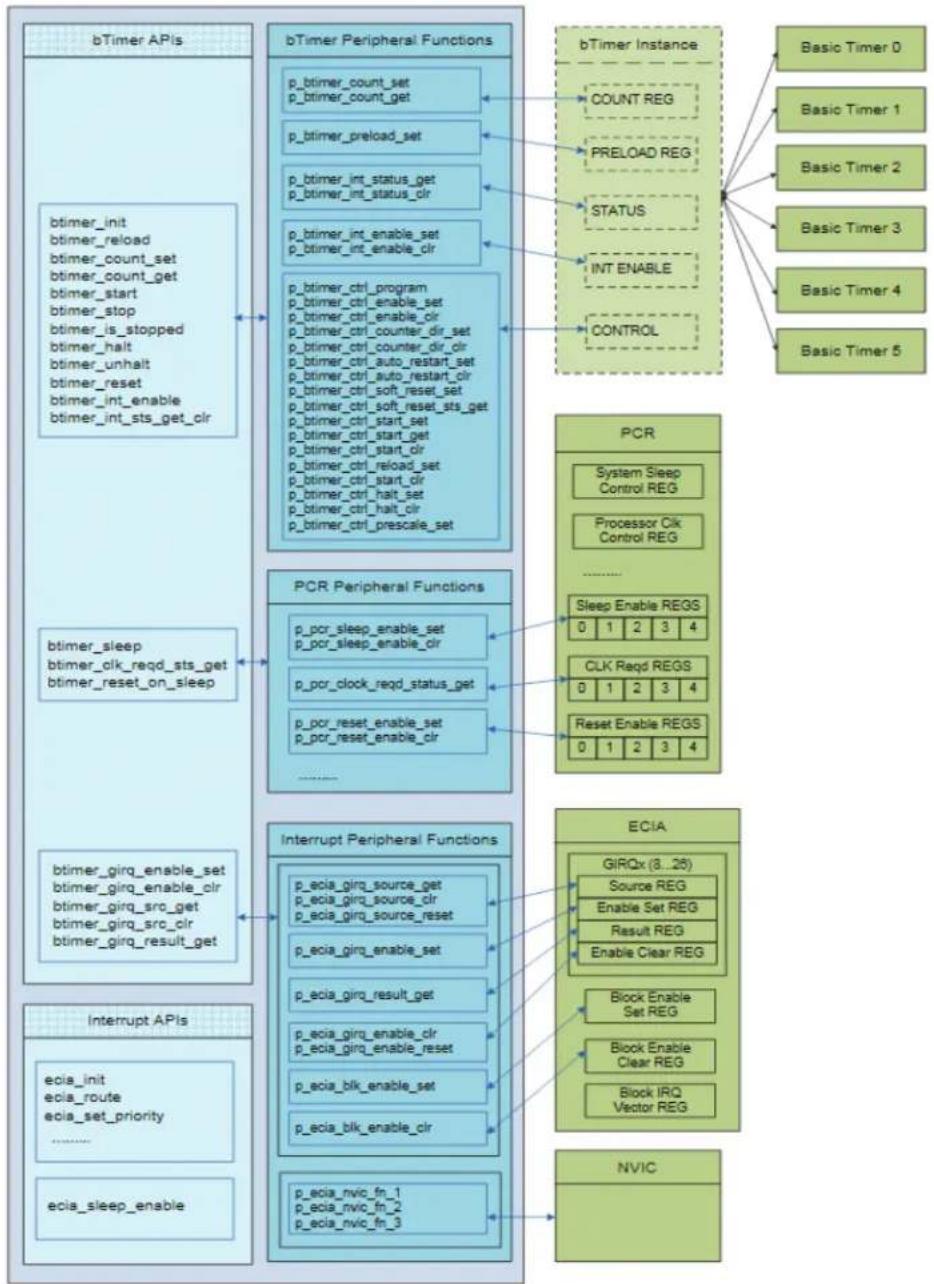
Chapter 1. Introduction
The peripheral software interface is provided to communicate with CEC/MEC family peripherals. It is composed of two layers:
- APIs
- Peripheral functions
Peripheral functions provide a low level interface to the hardware block.
The APIs are built over the peripheral functions. Applications are recommended to interface using the APIs. The APIs provide an interface to execute simple operations. The application or driver can use the APIs to perform a sequence of operations (through API call) to perform a task.
For some complex hardware peripheral, a driver would be provided which the application can integrate into their kernel/RTOS.
The libraries provided are not located in the ROM, they are software libraries that are linked to the project.
1.1 PARTS
This document covers the following parts:
• CEC1702 & MEC170x family devices
Chapter 2. Basic Timer
flowchart
graph TD
    A["bTimer APIs"] --> B["btimer_init<br>btimer_reload<br>btimer_count_set<br>btimer_count_get<br>btimer_start<br>btimer_stop<br>btimer_is_stopped<br>btimer_halt<br>btimer_unhalt<br>btimer_reset<br>btimer_int_enable<br>btimer_int_sts_get_clr"]
    B --> C["btimer_sleep<br>btimer_clk_reqd_sts_get<br>btimer_reset_on_sleep"]
    C --> D["btimer_girq_enable_set<br>btimer_girq_enable_clr<br>btimer_girq_src_get<br>btimer_girq_src_clr<br>btimer_girq_result_get"]
    D --> E["Interrupt APIs"]
    E --> F["ecia_init<br>ecia_route<br>ecia_set_priority<br>......<br>ecia_sleep_enable"]

    G["bTimer Peripheral Functions"] --> H["p_btimer_count_set<br>p_btimer_count_get"]
    H --> I["p_btimer_preload_set"]
    I --> J["p_btimer_int_status_get<br>p_btimer_int_status_clr"]
    J --> K["p_btimer_int_enable_set<br>p_btimer_int_enable_clr"]
    K --> L["p_btimer_ctrl_program<br>p_btimer_ctrl_enable_set<br>p_btimer_ctrl_enable_clr<br>p_btimer_ctrl_counter_dir_set<br>p_btimer_ctrl_counter_dir_clr<br>p_btimer_ctrl_auto_restart_set<br>p_btimer_ctrl_auto_restart_clr<br>p_btimer_ctrl_soft_reset_set<br>p_btimer_ctrl_soft_reset_sts_get<br>p_btimer_ctrl_start_set<br>p_btimer_ctrl_start_get<br>p_btimer_ctrl_start_clr<br>p_btimer_ctrl_reload_set<br>p_btimer_ctrl_start_clr<br>p_btimer_ctrl_halt_set<br>p_btimer_ctrl_halt_clr<br>p_btimer_ctrl_prescale_set"]

    M["PCR Peripheral Functions"] --> N["p_pcr_sleep_enable_set<br>p_pcr_sleep_enable_clr"]
    N --> O["p_pcr_clock_reqd_status_get"]
    O --> P["p_pcr_reset_enable_set<br>p_pcr_reset_enable_clr"]
    P --> Q["......"]

    R["Interrupt Peripheral Functions"] --> S["p_ecia_girq_source_get<br>p_ecia_girq_source_clr<br>p_ecia_girq_source_reset"]
    S --> T["p_ecia_girq_enable_set"]
    T --> U["p_ecia_girq_result_get"]
    U --> V["p_ecia_girq_enable_clr<br>p_ecia_girq_enable_reset"]
    V --> W["p_ecia_blk_enable_set"]
    W --> X["p_ecia_blk_enable_clr"]
    X --> Y["p_ecia_nvic_fn_1<br>p_ecia_nvic_fn_2<br>p_ecia_nvic_fn_3"]

    Z["ECIA"] --> AA["GIRQx (8..26)<br>Source REG<br>Enable Set REG<br>Result REG<br>Enable Clear REG"]
    AA --> AB["Block Enable Set REG"]
    AB --> AC["Block Enable Clear REG"]
    AC --> AD["Block IRQ Vector REG"]

    AE["bTimer Instance"] --> AF["COUNT REG"]
    AF --> AG["PRELOAD REG"]
    AG --> AH["STATUS"]
    AH --> AI["INT ENABLE"]
    AI --> AJ["CONTROL"]

    AK["Basic Timer 0"] --> AL["Basic Timer 1"] --> AM["Basic Timer 2"] --> AN["Basic Timer 3"] --> AO["Basic Timer 4"] --> AP["Basic Timer 5"]
2.1 BASIC TIMER APIS
The list of Basic Timer APIs:
- Basic Timer Initialization function
- btimer_init
- Functions to program and read the Basic Timer Counter
- btimer_count_set
- btimer_count_get
- Function to reload counter from Preload Register
- btimer_reload
- Functions for stopping and starting the basic Timer
- btimer_start
- btimer_stop
- btimer_is_started
- Function to perform basic timer soft reset
- btimer_reset
- Functions to halt/unhalt the timer counting
- btimer_halt
- btimer_unhalt
- Functions for Basic Timer interrupt
- btimer_interrupt_enable
- btimer_interrupt_status_get_clr
- Functions for Basic Timer GIRQ
- btimer_girq_enable_set
- btimer_girq_enable_clr
- btimer_girq_src_get
- btimer_girq_src_clr
- btimer_girq_result_get
- Functions for Basic Timer Sleep
- btimer_sleep
- btimer_clk_reqd_sts_get
- btimer_reset_on_sleep
2.1.1 btimer\_init
Function Header
void btimer_init(uint8_t btimer_id,
    uint16_t tmr_cntl,
    uint16_t prescaler,
    uint32_t initial_count,
    uint32_t preload_count)
Description
Initialize specified timer
Note: This function performs a soft reset of the timer before configuration.
Inputs
| Input Parameter Description | |
| btimer_id timer ID – PID_BTIMER_x (x => 0-5) | |
| tmr_cntl see tmr_cntl parameters below | |
| prescaler Timer prescaler | |
| initial_count initial count | |
| preload_count preload count | |
//
// Logical flags for tmr_cntl parameter of btimer_init
//
BTMR_AUTO_RESTART
BTMR_ONE_SHOT
BTMR_COUNT_UP
BTMR_COUNT_DOWN
BTMR_INT_EN
BTMR_NO_INT
Outputs
None
Example Usage
btimer_init (PID_BTIMER_0,
    BTMR_AUTO_RESTART + BTMR_COUNT_DOWN +
    BTMR_NO_INT,
    11,
    0,
    0);
2.1.2 btimer\_count\_set
Function Header
void btimer_count_set(uint8_t btimer_id, uint32_t count)
Description
Program timer's counter register
Note: Timer hardware may implement a 16-bit or 32-bit hardware counter. If the timer is 16-bit only the lower 16-bits of the count parameter are used. Timers 0-3 use 16-bit count value and Timer 4-5 use 32-bit count value.
Inputs
| Input Parameter Description | |
| btimer_id timer ID – PID_BTIMER_x (x => 0-5) | |
| count New counter value | |
Outputs
None
2.1.3 btimer\_count\_get
Function Header
uint32_t btimer_count_get(uint8_t btimer_id)
Description
Return current value of timer's count register
Note: Timers 0-3 have 16-bit count value and Timer 4-5 will have 32-bit count value.
Inputs
| Input Parameter Description | |
| btimer_id timer ID – PID_BTIMER_x (x => 0-5) |
Outputs
32-bit or 16-bit timer count value
2.1.4 btimer\_reload
Function Header
void btimer_reload(uint8_t btimer_id)
Description
Force timer to reload counter from preload register
Note: Hardware will only reload counter if timer is running.
Inputs
| Input Parameter Description | |
| btimer_id timer ID – PID_BTIMER_x (x => 0-5) |
Outputs
None
2.1.5 btimer\_start
Function Header
void btimer_start(uint8_t btimer_id)
Description
Start timer counting
Inputs
| Input Parameter Description |
| btimer_id timer ID – PID_BTIMER_x (x => 0-5) |
Outputs
None
2.1.6 btimer\_stop
Function Header
void btimer_stop(uint8_t btimer_id)
Description
Stop Timer
| Note: | When a stopped timer is started again it will reload the count register from preload value. |
Inputs
| Input Parameter Description |
| btimer_id timer ID – PID_BTIMER_x (x => 0-5) |
Outputs
None
2.1.7 btimer\_is\_started
Function Header
uint8_t btimer_is_started(uint8_t btimer_id)
Description
Return state of timer's START bit
Inputs
| Input Parameter Description |
| btimer_id timer ID - PID_BTIMER_x (x => 0-5) |
Outputs
0 (timer not started), 1 (timer started)
2.1.8 btimer\_reset
Function Header
void btimer_reset(uint8_t btimer_id)
Description
Perform soft reset of specified timer
Note: Soft reset set all registers to POR values. Spins 256 times waiting on hardware to clear reset bit (\~1.6us with 48MHz clock).
Inputs
Input Parameter Description
btimer_id timer ID - PID_BTIMER_x (x => 0-5)
Outputs
None
2.1.9 btimer\_halt
Function Header
void btimer_halt(uint8_t btimer_id)
Description
Halt timer counting with no reload on unhalt
Note: A halted timer will not reload the count register when unhalted, it will continue counting from the current count value.
Inputs
Input Parameter Description
btimer_id timer ID - PID_BTIMER_x (x => 0-5)
Outputs
None
2.1.10 btimer\_unhalt
Function Header
void btimer_unhalt(uint8_t btimer_id)
Description
Unhalt timer counting
Inputs
Input Parameter Description
btimer_id timer ID - PID_BTIMER_x (x => 0-5)
Outputs
None
2.1.11 btimer\_interrupt\_enable
Function Header
void btimer_interrupt_enable(uint8_t btimer_id, uint8_t ien)
Description
Enable/Disable specified timer's interrupt from the block
Inputs
| Input Parameter Description | |
| btimer_id timer ID – PID_BTIMER | x (x => 0-5) |
| ien 1 – Enable timer block interrupt | 0 – disable timer block interrupt |
Outputs
None
2.1.12 btimer\_interrupt\_status\_get\_clr
Function Header
uint8_t btimer_interrupt_status_get_clr(uint8_t btimer_id)
Description
Read Timer interrupt status and clear if set.
Inputs
| Input Parameter Description |
| btimer_id timer ID - PID_BTIMER_x (x => 0-5) |
Outputs
1 (Timer interrupt status set) else 0
2.1.13 btimer\_girq\_enable\_set
Function Header
void btimer_girq_enable_set(uint8_t btimer_id)
Description
Enables GIRQ enable bit for the timer
Inputs
| Input Parameter Description |
| btimer_id timer ID – PID_BTIMER_x (x => 0-5) |
Outputs
None
2.1.14 btimer\_girq\_enable\_clr
Function Header
void btimer_girq_enable_clr(uint8_t btimer_id)
Description
Clears GIRQ enable bit for the timer
Inputs
| Input Parameter Description |
| btimer_id timer ID – PID_BTIMER_x (x => 0-5) |
Outputs
None
2.1.15 btimer\_girq\_src\_get
Function Header
void btimer_girq_src_get(uint8_t btimer_id)
Description
Returns GIRQ source bit for the timer
Inputs
| Input Parameter Description |
| btimer_id timer ID – PID_BTIMER_x (x => 0-5) |
Outputs
0(source bit not set), Non-zero (source bit set)
2.1.16 btimer\_girq\_src\_clr
Function Header
void btimer_girq_src_clr(uint8_t btimer_id)
Description
Clears GIRQ source bit for the timer
Inputs
| Input Parameter Description | |
| btimer_id timer ID – P | D_BTIMER_x (x => 0-5) |
Outputs
None
2.1.17 btimer\_girq\_result\_get
Function Header
uint8_t btimer_girq_result_get(uint8_t btimer_id)
Description
Returns GIRQ result bit for the timer
Inputs
| Input Parameter Description | |
| btimer_id timer ID - PID_BTIMER_x (x => 0-5) |
Outputs
0(result bit not set), Non-zero (result bit set)
2.1.18 btimer\_sleep
Function Header
void btimer_sleep(uint8_t btimer_id, uint8_t sleep_en)
Description
Enable/Disable clock gating on idle of a timer
Inputs
| Input Parameter Description | |
| btimer_id timer ID - PID_BTIMER_x (x => 0-5) | |
| sleep_en 1 = Sleep Enable | 0 = Sleep Disable |
Outputs
None
2.1.19 btimer\_clk\_reqd\_sts\_get
Function Header
uint32_t btimer_clk_reqd_sts_get (uint8_t btimer_id)
Description
Returns clk required status
Inputs
| Input Parameter Description |
| btimer_id timer ID – PID_BTIMER_x (x => 0-5) |
Outputs
0(CLK not required), Non-zero (CLK required)
2.1.20 btimer\_reset\_on\_sleep
Function Header
void btimer_reset_on_sleep (uint8_t btimer_id, uint8_t reset_en)
Description
Enable/Disable timer block reset on sleep
Inputs
| Input Parameter Description | |
| btimer_id timer ID – PID_BTIMER_x (x => 0-5) | |
| reset_en 1 = Enable Reset on Sleep | |
| 0 = Disable Reset on Sleep | |
Outputs
None
2.2 BASIC TIMER PERIPHERAL FUNCTIONS
The list of Basic Timer Peripheral Functions:
- Functions to set and read Timer Counter Register
- btimer_count_get
- btimer_count_set
- Function to program the Preload
- btimer_preload_set
- Functions for basic timer interrupts
- btimer_int_status_get
- btimer_int_status_clear
- btimer_int_enable_set
- btimer_int_enable_clr
- Functions for Control Register
- btimer_ctrl_write
- btimer_ctrl_read
- btimer_ctrl_enable_set
- btimer_ctrl_enable_clr
- btimer_ctrl_counter_dir_set
- btimer_ctrl_counter_dir_clr
- btimer_ctrl_auto_restart_set
- btimer_ctrl_auto_restart_clr
- btimer_ctrl_soft_reset_set
- btimer_ctrl_soft_reset_sts_get
- btimer_ctrl_start_set
- btimer_ctrl_start_get
- btimer_ctrl_reload_set
- btimer_ctrl_reload_clr
- btimer_ctrl_halt_set
- btimer_ctrl_halt_clr
2.2.1 p\_btimer\_count\_set
Function Header
void p_btimer_count_set(uint8_t btimer_id, uint32_t count)
Description
Sets timer counter
Inputs
| Input Parameter Description | |
| btimer_id Timer ID – PID_BTIMER | x (x => 0-5) |
| count 32-bit counter | |
Outputs
None
2.2.2 p\_btimer\_count\_get
Function Header
uint32_t p_btimer_count_get (uint8_t btimer_id)
Description
Read the timer counter
Inputs
| Input Parameter Description |
| btimer_id Timer ID – PID_BTIMER_x (x => 0-5) |
Outputs
Counter value
2.2.3 p\_btimer\_preload\_set
Function Header
void p_btimer_preload_set(uint8_t btimer_id, uint32_t preload_count)
Description
Sets preload for the counter
Inputs
| Input Parameter Description |
| btimer_id Sets preload for the counter |
| preload_count 32-bit pre-load value |
Outputs
None
2.2.4 p\_btimer\_int\_status\_get
Function Header
uint8_t p_btimer_int_status_get (uint8_t btimer_id)
Description
Read the interrupt status bit in the timer block
Inputs
| Input Parameter Description |
| btimer_id Timer ID – PID_BTIMER_x (x => 0-5) |
Outputs
1 if interrupt status set, else 0
2.2.5 p\_btimer\_int\_status\_clear
Function Header
void p_btimer_int_status_clear (uint8_t btimer_id)
Description
Clears the interrupt status bit in the timer block
Inputs
| Input Parameter Description |
| btimer_id Timer ID – PID_BTIMER_x (x => 0-5) |
Outputs
None
2.2.6 p\_btimer\_int\_enable\_set
Function Header
void p_btimer_int_enable_set(uint8_t btimer_id)
Description
Sets interrupt enable bit in the timer block
Inputs
| Input Parameter Description |
| btimer_id Timer ID – PID_BTIMER_x (x => 0-5) |
Outputs
None
2.2.7 p\_btimer\_int\_enable\_clr
Function Header
void p_btimer_int_enable_clr(uint8_t btimer_id)
Description
Clears interrupt enable bit for the timer block
Inputs
| Input Parameter | Description |
| btimer_id Timer ID – PID_BTIMER_x (x => 0-5) | |
Outputs
None
2.2.8 p\_btimer\_ctrl\_write
Function Header
void p_btimer_ctrl_write (uint8_t btimer_id, uint32_t value)
Description
Writes the control register 32-bits
Inputs
| Input Parameter Description | |
| btimer_id Timer ID – PID_BTIMER_x (x => 0-5) | |
| Value 32-bit value to program | |
Outputs
None
2.2.9 p\_btimer\_ctrl\_read
Function Header
uint32_t p_btimer_ctrl_read (uint8_t btimer_id)
Description
Reads the control register
Inputs
| Input Parameter Description |
| btimer_id Timer ID – PID_BTIMER_x (x => 0-5) |
Outputs
32-bit value read
2.2.10 p\_btimer\_ctrl\_enable\_set
Function Header
void p_btimer_ctrl_enable_set(uint8_t btimer_id)
Description
Sets the enable bit in the control register
Inputs
| Input Parameter Description |
| btimer_id Timer ID – PID_BTIMER_x (x => 0-5) |
Outputs
None
2.2.11 p\_btimer\_ctrl\_enable\_clr
Function Header
void p_btimer_ctrl_enable_clr(uint8_t btimer_id)
Description
Clears the enable bit in the control register
Inputs
| Input Parameter Description |
| btimer_id Timer ID – PID_BTIMER_x (x => 0-5) |
Outputs
None
2.2.12 p\_btimer\_ctrl\_counter\_dir\_set
Function Header
void p_btimer_ctrl_counter_dir_set (uint8_t btimer_id)
Description
Sets counter direction bit in the control register
Inputs
| Input Parameter Description |
| btimer_id Timer ID – PID_BTIMER_x (x => 0-5) |
Outputs
None
2.2.13 p\_btimer\_ctrl\_counter\_dir\_clr
Function Header
void p_btimer_ctrl_counter_dir_clr(uint8_t btimer_id)
Description
Clears counter direction bit in the control register
Inputs
| Input Parameter Description |
| btimer_id Timer ID – PID_BTIMER_x (x => 0-5) |
Outputs
None
2.2.14 p\_btimer\_ctrl\_auto\_restart\_set
Function Header
void p_btimer_ctrl_auto_restart_set(uint8_t btimer_id)
Description
Sets auto restart bit in the control register
Inputs
| Input Parameter Description |
| btimer_id Timer ID – PID_BTIMER_x (x => 0-5) |
Outputs
None
2.2.15 p\_btimer\_ctrl\_auto\_restart\_clr
Function Header
void p_btimer_ctrl_auto_restart_clr(uint8_t btimer_id)
Description
Clears auto restart bit in the control register
Inputs
| Input Parameter Description |
| btimer_id Timer ID - PID_BTIMER_x (x => 0-5) |
Outputs
None
2.2.16 p\_btimer\_ctrl\_soft\_reset\_set
Function Header
void p_btimer_ctrl_soft_reset_set(uint8_t btimer_id)
Description
Sets soft reset bit in the control register
Inputs
| Input Parameter Description |
| btimer_id Timer ID – PID_BTIMER_x (x => 0-5) |
Outputs
None
2.2.17 p\_btimer\_ctrl\_soft\_reset\_sts\_get
Function Header
uint8_t p_btimer_ctrl_soft_reset_sts_get (uint8_t btimer_id)
Description
Read soft reset bit in the control register
Inputs
| Input Parameter Description |
| btimer_id Timer ID – PID_BTIMER_x (x => 0-5) |
Outputs
0 if soft reset status bit cleared; else non-zero value
2.2.18 p\_btimer\_ctrl\_start\_set
Function Header
void p_btimer_ctrl_start_set(uint8_t btimer_id)
Description
Sets start bit in the control register
Inputs
| Input Parameter Description |
| btimer_id Timer ID – PID_BTIMER_x (x => 0-5) |
Outputs
None
2.2.19 p\_btimer\_ctrl\_start\_get
Function Header
uint8_t p_btimer_ctrl_start_get (uint8_t btimer_id)
Description
Read start bit in the control register
Inputs
| Input Parameter Description |
| btimer_id Timer ID – PID_BTIMER_x (x => 0-5) |
Outputs
0 if start bit cleared; else non-zero value
2.2.20 p\_btimer\_ctrl\_start\_clr
Function Header
void p_btimer_ctrl_start_clr(uint8_t btimer_id)
Description
Clears start bit in the control register
Inputs
| Input Parameter Description |
| btimer_id Timer ID – PID_BTIMER_x (x => 0-5) |
Outputs
None
2.2.21 p\_btimer\_ctrl\_reload\_set
Function Header
void p_btimer_ctrl_reload_set(uint8_t btimer_id)
Description
Sets reload bit in the control register
Inputs
| Input Parameter Description | |
| btimer_id Timer ID – PID_BTIMER_x (x => 0-5) |
Outputs
None
2.2.22 p\_btimer\_ctrl\_reload\_clr
Function Header
void p_btimer_ctrl_reload_clr(uint8_t btimer_id)
Description
Clears reload bit in the control register
Inputs
| Input Parameter Description |
| btimer_id Timer ID – PID_BTIMER_x (x => 0-5) |
Outputs
None
2.2.23 p\_btimer\_ctrl\_halt\_set
Function Header
void p_btimer_ctrl_halt_set(uint8_t btimer_id)
Description
Sets halt bit in the control register
Inputs
| Input Parameter Description |
| btimer_id Timer ID – PID_BTIMER_x (x => 0-5) |
Outputs
None
2.2.24 p\_btimer\_ctrl\_halt\_clr
Function Header
void p_btimer_ctrl_halt_clr(uint8_t btimer_id)
Description
Clears halt bit in the control register
Inputs
| Input Parameter Description |
| btimer_id Timer ID – PID_BTIMER_x (x => 0-5) |
Outputs
None
Chapter 3. PWM
CEC/MEC family devices have up to 12 PWM channels and support PWM frequencies from 0.1 Hz to 500KHz.
The user can use the below APIs and can initiate the PWM channel & PWM frequency using the PWM_init routine.
The user can vary the duty cycle with a minimum interval of 1%.
PWM_enable should follow the PWM_init routine to start the PWM generation.
The user shall use the APIs below with a valid PWM Channel Number.
| PWM APIs | PWM Peripheral Functions | PWM Instance | Number of PWM's |
| PWM_initM_set_dutycycleM_sleep_enableM_sleep_disablen_gpio_configure | p_PWM_set_ON_timep_PWM_counter_ON_Time_read | PWMx Counter ON Time Register | PWM0PWM1PWM2PWM3PWM4PWM5PWM6PWM7PWM8PWM9PWM10 |
| p_PWM_set_OFF_timep_PWM_counter_OFF_Time_read | |||
| PWMx Counter OFF Time Register | |||
| p_PWM_set_predividerp_PWM_set_invertp_PWM_select_clockp_PWM_enablep_PWM_disablep_PWM_configuration_readp_PWM_configuration_write | PWMx Configuration Register | ||
| GPIO Peripheral Functions | |||
| PCR Peripheral Functions |
3.1 PWM APIS
The list of PWM APIs:
- PWM_init
- PWM_set_dutycycle
- PWM_sleep_enable
- PWM_sleep_disable
- pwm_gpio_configure
3.1.1 PWM\_init
Function Header
void PWM_init(uint8_t pwm_ch,
    uint32_t pwm_frequency,
    uint8_t invert,
    uint8_t dutycycle,
)
Description
Configure the PWM channel with required configuration.
Inputs
| Input Parameter | Description |
| pwm_ch Pwm ch – BPWMx_ch (x => 0-3) | |
| Pwm_frequency Period is calculated based on the pwm_frequencyPWM_frequency in Hz, use non-zero value only. | |
| Invert 0 – Invert not required (ON state is active High)1 - Invert output (ON state is active Low) | |
| Duty Cycle Duty Cycle in percentage, minimum resolution is of 1%. | |
Outputs
None
3.1.2 PWM\_set\_dutycycle
Function Header
void PWM_set_dutycycle(uint8_t pwm_ch,
    uint32_t pwm_frequency,
    uint8_t dutycycle
)
Description
Reinitialize or modify the duty cycle of any existing initialized PWM channel.
Inputs
| Input Parameter Description | |
| pwm_ch Pwm Ch – BPWMx_ch (x => 0-3) | |
| Pwm_frequency Period is calculated based on the pwm_frequency PWM_frequency in Hz, use non zero values. | |
| Duty Cycle Duty Cycle in percentage, minimum resolution is of 1%. |
Outputs
None
3.1.3 PWM\_sleep\_enable
Function Header
void PWM_sleep_enable(uint8_t pwm_ch)
Description
Disables the PWM channel and put the specific PWM channel into sleep. This is to reduce the power consumption and keep the device in very low power state.
Inputs
| Input Parameter Description | |
| pwm_ch Pwm ch | + BPWMx_ch (x => 0-3) |
Outputs
None
3.1.4 PWM\_sleep\_disable
Function Header
void PWM_sleep_disable(uint8_t pwm_ch)
Description
Disable the sleep of the specific pwm channel. Need to call bPWM_enable routine to start the PWM channel.
Inputs
| Input Parameter Description | |
| pwm_ch Pwm ch | + BPWMx_ch (x => 0-3) |
Outputs
None
3.1.5 PWM\_gpio\_configure
Function Header
void pwm_gpio_configure(uint8_t pwm_ch)
Description
Initializes the PWM channel GPIO pin based on the PWM channel ID.
Inputs
| Input Parameter Description | |
| pwm_ch Pwm ch | + BPWMx_ch (x => 0-3) |
Outputs
None
3.2 PWM PERIPHERAL FUNCTIONS
The list of PWM peripheral functions are listed below:
- p_PWM_set_ON_time
• p_PWM_counter_ON_Time_read - p_PWM_set_OFF_time
• p_PWM_counter_OFF_Time_read - p_PWM_set_predivider
- p_PWM_set_invert
- p_PWM_select_clock
- p_PWM_enable
• p_PWM_disable - p_PWM_configuration_read
- p_PWM_configuration_write
3.2.1 p\_PWM\_set\_ON\_time
Function Header
void p_PWM_set_ON_time (uint8_t pwm_ch, uint16_t ON_time)
Description
Load the PWMx Counter ON time.
Inputs
| Input Parameter Description | |
| Pwm_ch PWM channel number | |
| ON_time Time of Pulse ON | |
Outputs
None
3.2.2 p\_PWM\_counter\_ON\_Time\_read
Function Header
Uint32_t p_PWM_counter_ON_Time_read (uint8_t pwm_ch)
Description
Read the Counter ON Time register and returns its value.
Inputs
| Input Parameter Description |
| Pwm_ch PWM channel number |
Outputs
Returns counter value.
3.2.3 p\_PWM\_set\_OFF\_time
Function Header
void p_PWM_set_OFF_time (uint8_t pwm_ch, uint16_t OFF_time)
Description
Load the PWMx Counter OFF time.
Inputs
| Input Parameter Description | |
| Pwm_ch PWM channel number | |
| OFF_time Time of Pulse OFF | |
Outputs
None
3.2.4 p\_PWM\_counter\_OFF\_Time\_read
Function Header
Uint32_t p_PWM_counter_OFF_Time_read (uint8_t pwm_ch)
Description
Read the Counter OFF Time register and returns its value.
Inputs
| Input Parameter Description | |
| Pwm_ch PWM channel number |
Outputs
Returns counter value.
3.2.5 p\_PWM\_set\_predivider
Function Header
void p_PWM_set_predivider (uint8_t pwm_ch, uint8_t pre_divider)
Description
Based on PWM frequency, set the required pre_divider value. This is to choose the clock pulse for PWM generator.
Inputs
| Input Parameter Description | |
| Pwm_ch PWM channel number | |
| Pre-divider Divider value to choose | the clock input |
Outputs
None
3.2.6 p\_PWM\_set\_invert
Function Header
void p_PWM_set_invert (uint8_t pwm_ch,
    uint8_t invert
)
Description
If no invert is required load value 0, if invert output is required load value 1.
Inputs
| Input Parameter Description | |
| Pwm_ch PWM channel number | |
| Invert bit 0 – Invert Off, PWM | output High for Active High1 - Invert ON, PWM output High for Active Low. |
Outputs
None
3.2.7 p\_PWM\_select\_clock
Function Header
void p_PWM_select_clock (uint8_t pwm_ch, uint8_t Clock_source)
Description
Choose the clock source required for PWM generator.
Inputs
| Input Parameter Description | |
| Pwm_ch PWM channel number | |
| Clock_Source 0 – High Clock – 48 | MHz Clock1 - Low Clock - 100KHz Clock |
Outputs
None
3.2.8 p\_PWM\_enable
Function Header
void p_PWM_enable (uint8_t pwm_ch)
Description
Set's the enable bit in the PWM Configuration register.
Inputs
| Input Parameter Description | |
| Pwm_ch PWM channel number |
Outputs
None
3.2.9 p\_PWM\_disable
Function Header
void p_PWM_disable (uint8_t pwm_ch)
Description
Set the disable bit in the PWM configuration register.
Inputs
| Input Parameter Description | |
| Pwm_ch PWM channel number |
Outputs
None
3.2.10 p\_PWM\_configuration\_read
Function Header
uint32_t PWM_configuration_read(uint8_t pwm_ch)
Description
Reads the Configuration register and returns its value.
Inputs
| Input Parameter | Description |
| pwm_ch Pwm ch | + BPWMx_ch (x => 0-3) |
Outputs
Returns the Configuration register Value.
3.2.11 p\_PWM\_configuration\_write
Function Header
void PWM_configuration_read(uint8_t pwm_ch, uint32_t configuration)
Description
Update the configuration register value.
Inputs
| Input Parameter Description | |
| pwm_ch Pwm ch – BPWMx_ch (x => 0-3) | |
| Configuration Configuration value as per register settings. |
Outputs
Returns the Configuration register Value.
Chapter 4. GPIO
| GPIO APIs | GPIO Peripheral Functions | GPIO Registers | Number of GPIO's |
| gpio_init | p_gpio_is_valid | ||
| gpio_property_set | p_gpio_ctrl_get | GPIO Control 1 register | GPIO 000 |
| gpio_property_get | p_gpio_ctrl_set | ||
| gpio_output_set | p_gpio_ctrl2_get | GPIO control 2 register | To |
| gpio_input_get | p_gpio_ctrl2_set | GPIO input register | |
| gpio_slewRate_set | p_gpio_pad_get | GPIO 276 | |
| gpio_slewRate_get | p_gpio_alt_out | GPIO output register | |
| gpio_driveStr_set | p_gpio_mux_set | ||
| gpio_driveStr_get | p_gpio_polarity_set | ||
| p_gpio_output_write_enable | |||
| p_gpio_dir_set | |||
| p_gpio_obuff_set | |||
| p_gpio_idet_set | |||
| p_gpio_pwrgate_set | |||
| p_gpio_pud_set | |||
| p_gpio_input_get | |||
| p_gpio_output_set |
4.1 GPIO APIS
The list of GPIO APIs:
- gpio_init
- gpio_property_set
- gpio_property_get
- gpio_output_set
- gpio_input_get
- gpio_slewRate_get
- gpio_slewRate_set
- gpio_driveStr_get
- gpio_driveStr_set
4.1.1 gpio\_init
Function Header
uint8_t gpio_init( enum GPIO_PIN pin,
    enum GPIO_MUX new_mux,
    enum GPIO_POLARITY new_pol,
    enum GPIO_DIR new_dir,
    enum GPIO_OUTDRV new_obuf,
    enum GPIO_INTDET new_idet,
    enum GPIO_PWRGATE new_pwrg,
    enum GPIO_PUD new_pud
)
Description
Initializes the specified GPIO Pin
Inputs
| Input Parameter Description | |
| pin 0-based GPIO ID | |
| new_mux New output mux control mode | GPIO_MUX_GPIO – GPIO modeGPIO_MUX_ALT_FUNC1 – Signal 1 modeGPIO_MUX_ALT_FUNC2 – Signal 2 modeGPIO_MUX_ALT_FUNC3 – Signal 3 mode |
| new_pol Polarity mode | GPIO_NON_INVERTEDGPIO_INVERTED |
| new_dir GPIO direction | GPIO_INPUTGPIO_OUTPUT |
| new_obuf GPIO pin's output buffer type | GPIO_PUSH_PULLGPIO_OPEN_DRAIN |
| new_idet GPIO pin's interrupt detection mode | GPIO_INTDET_LVL_LOGPIO_INTDET_LVL_HIGPIO_INTDET_DISABLEDGPIO_INTDET_EDG_RISEGPIO_INTDET_EDG_FALLGPIO_INTDET_EDG_BOTH |
| new_pwrg GPIO pin's power source | GPIO_VCC1_SUSGPIO_VCC2_MAINGPIO_ALWAYS_UNPWRDGPIO_ALWAYS_PWRD |
| new_pud GPIO pin's internal resistor mode | GPIO_PUD_NONEGPIO_PU-Pull up modeGPIO_PD-Pull down modeGPIO_KEEPER |
Outputs
1 = success, 0 = fail
4.1.2 gpio\_property\_set
Function Header
uint8_t gpio_property_set (enum GPIO_PIN pin,
    enum GPIO_PROPERTY gpio_prop,
    uint32_t new_prop_val
)
Description
Enables the user to change any property of the specified gpio pin at run time Inputs
| Input Parameter Description | |
| pin 0-based GPIO ID | |
| gpio_prop Property type that is to be updatedGPIO_PROP_PU_PDGPIO_PROP_PWR_GATEGPIO_PROP_INT_DETGPIO_PROP_OBUFF_TYPEGPIO_PROP_DIRGPIO_PROP_OUT_SRCGPIO_PROP_POLARITYGPIO_PROP_MUX_SELGPIO_PROP_ALL | |
| new_prop_val New value of the | propertyGPIO_PROP_PU_PDGPIO_PUD_NONEGPIO_PU-Pull up modeGPIO_PD-Pull down modeGPIO_KEEPERGPIO_PROP_PWR_GATEGPIO_VTRGPIO_VCC_MAINGPIO_ALWAYS_UNPWRDGPIO_PROP_INT_DETGPIO_INTDET_LVL_LOGPIO_INTDET_LVL_HIGPIO_INTDET_DISABLEDGPIO_INTDET_EDG_RISEGPIO_INTDET_EDG_FALLGPIO_INTDET_EDG_BOTHGPIO_PROP_OBUFF_TYPEGPIO_PUSH_PULLGPIO_OPEN_DRAINGPIO_PROP_DIRGPIO_INPUTGPIO_OUTPUTGPIO_PROP_OUT_SRCGPIO_ALT_OUT_ENGPIO_ALT_OUT_DISGPIO_PROP_POLARITYGPIO_NON_INVERTEDGPIO_INVERTEDGPIO_PROP_MUX_SELGPIO_MUX_GPIOGPIO_MUX_ALT_FUNC1GPIO_MUX_ALT_FUNC2GPIO_MUX_ALT_FUNC3 |
Outputs
1 = success, 0 = fail
4.1.3 gpio\_property\_get
Function Header
uint8_t gpio_property_set (enum GPIO_PIN pin, enum GPIO_PROPERTY gpio_prop)
Description
Returns the current value of the requested property type of the specified gpio pin
Inputs
| Input Parameter Description | |
| pin 0-based GPIO ID | |
| gpio_prop Property type that is to be readGPIO_PROP_PU_PDGPIO_PROP_PWR_GATEGPIO_PROP_INT_DETGPIO_PROP_OBUFF_TYPEGPIO_PROP_DIRGPIO_PROP_OUT_SRCGPIO_PROP_POLARITYGPIO_PROP_MUX_SEL | |
Outputs
Property values (refer data sheet), 0xFF = fail
4.1.4 gpio\_output\_set
Function Header
uint8_t gpio_output_set( enum GPIO_PIN pin, enum GPIO_ALT_OUT out_src, const uint32_t gpio_state )
Description
Writes the output value to the specified gpio pin depending upon the output source register.
Inputs
| Input Parameter Description | |
| pin 0-based GPIO ID | |
| out_src Output source register | GPIO_ALT_OUT_EN – bit[16] of control 1registerGPIO_ALT_OUT_DIS – output register |
| gpio_state Desired pin state | |
Outputs
1 = success, 0 = fail
4.1.5 gpio\_input\_get
Function Header
uint8_t gpio_input_get( enum GPIO_PIN pin )
Description
Reads the GPIO pin's input register using the gpio input register.
Inputs
| Input Parameter Description | |
| pin 0-based GPIO ID |
Outputs
0 or 1 = pin state, 0xFF = fail
4.1.6 gpio\_slewRate\_get
Function Header
uint8_t gpio_slewRate_get( enum GPIO_PIN pin )
Description
Returns the current slew rate configuration of the specified GPIO Pin.
Inputs
| Input Parameter Description | |
| pin 0-based GPIO ID |
Outputs
Pin slew rate: 0 = slow, 1 = fast, 0xFF = fail
4.1.7 gpio\_slewRate\_set
Function Header
uint8_t gpio_slewRate_set (enum GPIO_PIN pin, enum GPIO_SLEW new_slew)
Description
Programs the slew rate configuration for the specified GPIO Pin.
Inputs
| Input Parameter Description | |
| gpio_id gpio_id 0-based GPIO ID | |
| new_slew new slew rate setting | GPIO_SLEW_SLOWGPIO_SLEW_FAST |
Outputs
1 = success, 0 = fail
4.1.8 gpio\_driveStr\_get
Function Header
uint8_t gpio_driveStr_get( enum GPIO_PIN pin )
Description
Reads the current drive strength setting of the specified gpio pin.
Inputs
| Input Parameter Description | |
| pin 0-based GPIO ID |
Outputs
Pin Drive Strength: 0 = 2mA, 1 = 4mA, 2 = 8mA, 3 = 12mA, 0xFF = fail
4.1.9 gpio\_driveStr\_set
Function Header
uint8_t gpio_driveStr_set (enum GPIO_PIN pin, enum GPIO_DRV drv_str)
Description
Programs the drive strength configuration for the specified gpio pin.
Inputs
| Input Parameter Description | |
| pin 0-based GPIO ID | |
| drv_str Drive strength value | GPIO_DRV_2MAGPIO_DRV_4MAGPIO_DRV_8MAGPIO_DRV_12MA |
Outputs
1 = success, 0 = fail
4.2 GPIO PERIPHERAL FUNCTIONS
List of GPIO Peripheral functions:
- p_gpio_is_valid
- p_gpio_ctrl_get
- p_gpio_ctrl_set
- p_gpio_ctrl2_get
- p_gpio_ctrl2_set
- p_gpio_pad_get
- p_gpio_alt_out
- p_gpio_mux_set
- p_gpio_polarity_set
- p_gpio_output_write_enable
- p_gpio_dir_set
- p_gpio_obuff_set
- p_gpio_idet_set
- p_gpio_pwrgate_set
-
p_gpio_pud_set
-
p_gpio_input_get
- p_gpio_output_set
4.2.1 p\_gpio\_is\_valid
Function Header
uint8_t p_gpio_is_valid (enum GPIO_PIN pin)
Description
Checks if the specified gpio pin has been implemented in the hardware.
Inputs
| Input Parameter Description | |
| pin 0-based GPIO ID |
Outputs
1 = valid, 0 = invalid
4.2.2 p\_gpio\_ctrl\_get
Function Header
uint32_t p_gpio_ctrl_get (enum GPIO_PIN pin)
Description
Reads the contents of the control 1 register of the specified gpio pin
Inputs
| Input Parameter Description | |
| pin 0-based GPIO ID |
Outputs
32-bit value of GPIO pin's control 1 register contents
4.2.3 p\_gpio\_ctrl\_set
Function Header
void p_gpio_ctrl_set (enum GPIO_PIN pin, uint32_t new_ctrl)
Description
Writes to the control 1 register of the specified gpio pin.
Inputs
| Input Parameter Description | |
| pin 0-based GPIO ID | |
| new_ctrl 32-bit value of the new value | |
Outputs
None
4.2.4 p\_gpio\_ctrl2\_get
Function Header
uint8_t p_gpio_ctrl2_get (enum GPIO_PIN pin)
Description
Reads the contents of the control 2 register of the specified gpio pin Inputs
| Input Parameter Description | |
| pin 0-based GPIO ID |
Outputs
GPIO pin's control 2 register contents
4.2.5 p\_gpio\_ctrl2\_set
Function Header
void p_gpio_ctrl2_set (enum GPIO_PIN pin, uint8_t new_ctrl2)
Description
Writes to the control 2 register of the specified gpio pin.
Inputs
| Input Parameter Description | |
| pin 0-based GPIO ID | |
| new_ctrl2 32-bit value of the new value | |
Outputs
None
4.2.6 p\_gpio\_pad\_get
Function Header
uint8_t p_gpio_pad_get (enum GPIO_PIN pin)
Description
Read GPIO pin's input via the GPIO_INPUT bit of the control register.
Note: Performs a byte read of offset 3 of the GPIO Pin's 32-bit control 1 register.
Inputs
| Input Parameter Description | |
| pin 0-based GPIO ID |
Outputs
Current state of the gpio pin
4.2.7 p\_gpio\_alt\_out
Function Header
void p_gpio_alt_out (enum GPIO_PIN pin, uint8_t new_val)
Description
Writes to the gpio pin via the ALTERNATE_GPIO_DATA bit of the control 1 register.
Note 1: To use this feature, 'Output GPIO Write Enable' bit should be cleared in the GPIO Control 1 register.
2: Performs a byte wide write to byte offset 2 of the GPIO Pin's 32-bit configuration register. No read-modify-write.
Inputs
| Input Parameter Description | |
| pin 0-based GPIO ID | |
| new_val New output value | |
Outputs
None
4.2.8 p\_gpio\_mux\_set
Function Header
void p_gpio_mux_set (enum GPIO_PIN pin, uint8_t new_mux)
Description
Sets the mode for the gpio pin's output mux.
Inputs
| Input Parameter Description | |
| pin 0-based GPIO ID | |
| new_mux New mux mode | GPIO_MUX_GPIO – GPIO modeGPIO_MUX_ALT_FUNC1 – Signal 1 modeGPIO_MUX_ALT_FUNC2 – Signal 2 modeGPIO_MUX_ALT_FUNC3 – Signal 3 mode |
Outputs
None
4.2.9 p\_gpio\_polarity\_set
Function Header
void p_gpio_polarity_set (enum GPIO_PIN pin, enum GPIO_POLARITY invert)
Description
Sets the mode for the gpio pin's polarity
Inputs
| Input Parameter Description | |
| pin 0-based GPIO ID | |
| invert New polarity mode | GPIO_NON_INVERTEDGPIO_INVERTED |
Outputs
None
4.2.10 p\_gpio\_output\_write\_enable
Function Header
void p_gpio_outen_set (enum GPIO_PIN pin, enum GPIO_ALT_OUT enable_par_out)
Description
Selects the output source register for the specified gpio pin.
Inputs
| Input Parameter Description | |
| pin 0-based GPIO ID | |
| enable_par_out Output register | GPIO_ALT_OUT_EN – bit[16] of control 1 registerGPIO_ALT_OUT_DIS – gpio output register |
Outputs
None
4.2.11 p\_gpio\_dir\_set
Function Header
void p_gpio_dir_set (enum GPIO_PIN pin, enum GPIO_DIR dir_output)
Description
Sets the direction of the specified gpio pin
Inputs
| Input Parameter Description | |
| pin 0-based GPIO ID | |
| dir_output Direction mode value | GPIO_INPUTGPIO_OUTPUT |
Outputs
None
4.2.12 p\_gpio\_obuff\_set
Function Header
void p_gpio_obuff_set (enum GPIO_PIN pin, enum GPIO_OUTDRV new_obuf)
Description
Selects the output buffer for the specified gpio pin
Inputs
| Input Parameter Description | |
| pin 0-based GPIO ID | |
| new_obuff Output buffer type | GPIO_PUSH_PULLGPIO_OPEN_DRAIN |
Outputs
None
4.2.13 p\_gpio\_idet\_set
Function Header
void p_gpio_idet_set (enum GPIO_PIN pin, enum GPIO_INTDET new_idet)
Description
Selects the interrupt detection mode for the specified gpio pin.
Note: This function accounts for all the possible combinations including bit[7] - EDGE_ENABLE of the control 1 register.
Inputs
| Input Parameter Description | |
| pin 0-based GPIO ID | |
| new_idet Interrupt detection mode | GPIO_INTDET_LVL_LOGPIO_INTDET_LVL_HIGPIO_INTDET_DISABLEDGPIO_INTDET_EDG_RISEGPIO_INTDET_EDG_FALLGPIO_INTDET_EDG_BOTH |
Outputs
None
4.2.14 p\_gpio\_pwrgate\_set
Function Header
void p_gpio_pwrgate_set (enum GPIO_PIN pin, enum GPIO_PWRGATE new_pwrg)
Description
Selects the power gating source for the specified gpio pin.
Inputs
| Input Parameter Description | |
| pin 0-based GPIO ID | |
| new_pwrg Power gate mode | GPIO_VTRGPIO_VCC_MAINGPIO_ALWAYS_UNPWRD |
Outputs
None
4.2.15 p\_gpio\_pud\_set
Function Header
void p_gpio_pud_set (enum GPIO_PIN pin, enum GPIO_PUD new_pud)
Description
Selects the internal resistor mode for the specified gpio pin
Inputs
| Input Parameter Description | |
| pin 0-based GPIO ID | |
| new_pud Internal resistor mode | selectGPIO_PUD_NONEGPIO_PU – Pull up modeGPIO_PD – Pull down modeGPIO_KEEPER |
Outputs
None
4.2.16 p\_gpio\_input\_get
Function Header
uint8_t p_gpio_input_get (enum GPIO_PIN pin)
Description
Reads the input value of the specified gpio pin using the gpio input register.
Inputs
| Input Parameter Description | |
| pin 0-based GPIO ID |
Outputs
0 or 1 = gpio input state, 0xFF = invalid pin
4.2.17 p\_gpio\_output\_set
Function Header
void p_gpio_output_set (enum GPIO_PIN pin, const uint32_t new_val)
Description
Writes to the gpio output register of the specified gpio pin.
Inputs
| Input Parameter Description | |
| pin 0-based GPIO ID | |
| New_val New output value | |
Outputs
None
Chapter 5. I2C/SMBus Driver
5.1 I2C/SMBUS DRIVER APIS & CALLBACKS
- Driver Set Up & Initialization
- smb_callback
- smb_register_eventFlag_and_callback
- smb_dma_isr
- s m b _ i s r
- smbus_main_task
- smbus_app_timer
- smbus_init_timer
- Configuring I ^2 C/SMBus Controller
- smbus_configure_and_enable
- smbus_disable
- smb_enable_timeouts
- MASTER APIs
- smb_busyStatus_get
- smb_portBusyStatus_get
- smb_change_port
- smb_set_speed
- smb_protocol_execute
- smb_protocol_execute_blocking
- Master callback function
- SLAVE APIs
- smb_register_slave
- smb_deregister_slave
- smbApp_slave_callback
5.2 I2C/SMBUS DRIVER CONFIGURATION
The I ^2 C/SMBus driver can be customized and configured based on the requirements. User needs to update the smb_config_user.h file. The file will have the following entries:
/* Maximum number of smbus controller */
#define MAX_SMB 4

/* Maximum number of ports per SMBus controller */
#define SMB_MAX_PORT_PER_CHANNEL11

/* Maximum number of buffers per slave controller */
#define SMB_MAX_NUM_SLAVE_BUFFER 8

/* Size of buffer on each controller (must be greater than 4) */
#define SLAVE1_BUFFER_SIZE64
#define SLAVE2_BUFFER_SIZE64
#define SLAVE3_BUFFER_SIZE64
#define SLAVE4_BUFFER_SIZE64

/* Maximum number of application per slave controller */
#define SMB_MAX_NUM_SLAVE_APP 5
5.3 DRIVER SET UP & INITIALIZATION
FreeRTOS
For hooking-in the I^2C/SMBus driver to FreeRTOS, it needs certain services and calls. In summary, following is the sequence to be followed:
- Create a I ^2 C/SMBus callback function whose prototype is: void smb_callback(UINT8 channel,UINT8 eventType,UINT8 Victoria)
- In the irq12 interrupt service routine call smb_isr function
- In the irq13 interrupt service routine call smb_dma_isr function
- As a part of global initialization (before entering freeRTOS) call smbus_init_task function
- In FreeRTOS:
a) Create a freeRTOS event flag for I ^2 C/SMBus driver purpose
b) Register the event flag and the I ^2 C/SMBus callback using the
c) smb_register_eventFlag_and_callback function
d) Create a freeRTOS timer which is set to call
e) smbus_app_timer every 10ms
f) Create a FreeRTOS task with stack size 512 (TBD) bytes with smbus_main as the call back function
SKERN
For hooking-in the I^2C/SMBus driver to SKERN, following sequence needs to be followed:
- In cfg.h, create a task (task number can vary) for I ^2 C/SMBus as shown below:
#define TASK_01    smbus
#define PRIORITY_TASK_01_EVENTTASK    HIGH
#define PRIORITY_TASK_01_EVENTTIMEOUT HIGH
#define ENABLE_TASK_01_EVENTINTR 1
#define ENABLE_TASK_01_EVENTTASK 1
#define ENABLE_TASK_01_EVENTTIMER 1
Note: This will automatically create function declarations for SMBUS_init_task and SMBUS_main_task.
- In the irq12 interrupt service routine call smb_isr function
- In the irq13 interrupt service routine call smb_dma_isr function
5.3.1 smb\_callback
Function Header
void smb_callback(const UINT8 channel, const UINT8 eventType, const UINT8 eventValue)
Description
This function is the callback function which is invoked by I ^2 C/SMBus driver at various instances for notifications.
Inputs
| Input Parameter Description | |
| channel SMB_CHANNEL_x - x is | 1 to 4 |
| eventType the type of event for notification | |
| eventValue parameter for the notification, if any | |
| eventType | |
| SMB_CBK_DISABLED controller is disabled | |
| SMB_CBK_HW_ENABLED controller is enabled | |
| SMB_CBK_BER bus error on the controller | |
| SMB_CBK_BUSY waiting for current transaction to | completebefore disabling |
| SMB_CBK_PORT_ERROR_SET Error in port (clk/data not high) | |
| SMB_CBK_PORT_ERROR_CLR | Port is good (clk/data high) |
Outputs
None
5.3.2 smb\_register\_eventFlag\_and\_callback
Function Header
void smb_register_eventFlag_and_callback(EventGroupHandle_t *ptr_event_flag_handle, SMB_CALLBACK_FUNC_PTR pCallback)
Description
Register FreeRTOS event flag. This function needs to be called only in FreeRTOS framework.
Inputs
| Input Parameter Description | |
| ptr_event_flag | ptr_event_flag pointer to RTOS event flag structure |
| pCallback pointer to callback function | |
Outputs
None
5.3.3 smb\_dma\_isr
Function Header
void smb_dma_isr(void)
Description
This function takes care of I ^2 C/SMBus dma interrupts. This needs to be called in irq13 interrupt routine from the application code. I ^2 C/SMBus dma are dma controller instance 0 to 7.
Inputs
None
Outputs
None
5.3.4 smb\_isr
Function Header
void smb_isr(void)
Description
The main entry point for I^2C/SMBus interrupt service routine. This needs to be called in irq12 interrupt routine from the application code.
Inputs
None
Outputs
None
5.3.5 smbus\_main\_task
Function Header (skern)
VOID smbus_main_task(enum EVENT_TYPE call_type)
Function Header (freeRTOS)
void smbus_main(void *pvParameters)
Description
This function performs all the I ^2 C/SMBus tasks. This function is passed as the entry for FreeRTOS and is the main task for SKERN.
Inputs
| Input Parameter Description | |
| Call_type Event Type | - Interrupt/Task/Timer |
| Input Parameter Description | |
| pvParameters Any parameters passed by application |
Outputs
None
5.3.6 smbus\_app\_timer
Function Header
void smbus_app_timer(void)
Description
I^2C/SMBus application timer function.
Note: This function internally sets flag to call smbus_timer_task. This function is only required for RTOS.
Inputs
None
Outputs
None
5.3.7 smbus\_init\_task
Function Header
void smbus_init_task (void)
Description
This function initializes the I^2C/SMBus data structures.
Note: This function needs to be called before entering FreeRTOS.
Inputs
None
Outputs
None
5.4 CONFIGURING I2C/SMBUS CONTROLLER
5.4.1 smbus\_configure\_and\_enable
Function Header
void smbus_configure_and_enable (UINT8 channel,
    UINT8 own_address,
    UINT8 speed,
    UINT8 port,
    UINT8 configFlag)
Description
This function can be used to start and enable the I²C/SMBus controller Inputs
| Input Parameter Description | |
| channel SMB_CHANNEL_x - x is | 1 to 4 |
| own_address 7-bit smb address | |
| speed SMBUS_SPEED_100KHZ | $MBUS_SPEED_400KHZ |
| SMBUS_SPEED_1MHZ | |
| port default port on the controller | |
| configValue Bit 0 - set to enable | Bit 2 - enable Fairness |
Outputs
None
5.4.2 smbus\_disable
Function Header
void smbus_disable(UINT8 channel)
Description
This function can be used to disable the I ^2 C/SMBus controller.
Note: Make the sure the controller was enabled prior to using this function.
Inputs
| Input Parameter Description |
| channel SMB_CHANNEL_x - x is 1 to 4 |
Outputs
None
5.4.3 smb\_enable\_timeouts
Function Header
void smb_enable_timeouts(const UINT8 channel, const UINT8 timeoutsFlag)
Description
This function enables timeouts.
Inputs
| Input Parameter Description | |
| channel SMB_CHANNEL_x - | x is 1 to 4 |
| timeoutsFlag Timeout flag as per BYTE0 of completion register | |
timeoutsFlag- timeoutsFlag is as per BYTE0 of completion register
BIT 2 – Device Timeout enable
BIT 3 – Master Cumulative Timeout enable
BIT 4 – Slave Cumulative Timeout enable
BIT 5 – Bus Idle Detect Timeout enable
Outputs
None
5.5 MASTER APIS
The steps to initiate any master transaction are as follows:
-
Check if I ^2 C/SMBus resource is available using busy status API
-
If I ^2 C/SMBus resource is available:
a) Change the port or speed (if desired)
b) Initiate the master transaction using smb_protocol_execute API.
5.5.1 smb\_busyStatus\_get
Function Header
UINT8 smb_busyStatus_get (const UINT8 channel)
Description
This function checks if master resource is available on the default port.
Inputs
| Input Parameter Description |
| channel SMB_CHANNEL_x - x is 1 to 4 |
Outputs
MASTER_BUSY-controller or default port is busy
MASTER_AVAILABLE- controller is available for use on the default port
Usage
/* Get SMBus resource status */
status = smb_busyStatus_get(SMB_CHANNEL_1);

if (MASTER_BUSY == status)
{
    trace0(0, SMB_APP, 0, "smbApp_master_request: smbus is busy");
    /* Steps for retry */
    ...
    ...
    }
    /* Proceed to smb_protocol_execute to initiate master request */
5.5.2 smb\_portBusyStatus\_get
Function Header
UINT8 smb_portBusyStatus_get (const UINT8 channel, const UINT8 port)
Description
This function checks if master resource is available on the queried port.
Inputs
| Input Parameter Description | |
| channel SMB_CHANNEL_x - x is | 1 to 4 |
| port port on the particular channel | for which busy status is required |
Outputs
MASTER_BUSY- controller or port is busy
MASTER_AVAILABLE- controller is available for use on the port
Usage
/* Get SMBus resource status */
status = smb_portBusyStatus_get(SMB_CHANNEL_1, SMB_PORT_1);

if (MASTER_BUSY == status)
{
trace0(0, SMB_APP, 0, "smbApp_master_request: smbus is busy");
/* Steps for retry */
...
}
/* Proceed to smb_protocol_execute to initiate master request */
5.5.3 smb\_change\_port
Function Header
UINT8 smb_change_port(const UINT8 channel, const UINT8 port)
Description
This function changes the controller port
Inputs
| Input Parameter Description | |
| channel SMB_CHANNEL_x - x is | 1 to 4 |
| port port on the particular channel | for which busy status is required |
Outputs
MASTER_OK- port change success
MASTER_ERROR- port or controller busy / port change error
5.5.4 smb\_set\_speed
Function Header
void smb_set_speed(const UINT8 channel, const UINT8 speed)
Description
This function changes I^2C/SMBus speed
Inputs
| Input Parameter Description | |
| channel SMB_CHANNEL_x - x is | 1 to 4 |
| speed SMBUS_SPEED_100KHZ | $MBUS_SPEED_400KHZ |
| SMBUS_SPEED_1MHZ | |
Outputs
None
Example Usage
None
5.5.5 smb\_protocol\_execute
Function Header
UINT8 smb_protocol_execute (const UINT8 channel,
UINT8 *buffer_ptr,
const UINT8 smb_protocol,
const UINT8 writeCount,
const UINT8 pecEnable,
MASTER_FUNC_PTR func_ptr,
const UINT8 readChainedFlag,
const UINT8 writeChainedFlag)
Description
Initiates I^2C/SMBus master operation. This function is called by the application whenever it wants to initiate a master transaction on the I^2C/SMBus .
Note: For Read Block protocol the application should provide an 80 byte buffer.
Inputs
| Input Parameter Description | |
| channel SMB_CHANNEL_x - x | is 1 to 4 |
| buffer_ptr Buffer for the I | ^2C/SMBus transaction |
| smb_protocol I | ^2C/SMBus protocol Byte |
| writeCount Number of bytes to transmit | |
| pecEnable Flag to enable/disable PEC | |
| func_ptr Function to call after success/failure of the transaction. This function will be invoked on completion of transaction with status. The function type is:typedef void (MASTER_FUNC_PTR)(UINT8, UINT8 *)The first parameter is the status, the next is the buffer_ptr that was passed. | |
| readChainedFlag flag to indicate if read needs to be done using dma chaining | |
| writeChainedFlag flag to indicate if write needs to be done using dma chaining | |
| smb_protocol |
| SMB_I2C_WRITE |
| SMB_I2C_READ |
| SMB_I2C_COMBINED |
| SMB_SEND_BYTE |
| SMB_RECEIVE_BYTE |
| SMB_WRITE_BYTE |
| SMB_WRITE_WORD |
| SMB_READ_BYTE |
| SMB_READ_WORD |
| SMB_WRITE_BLOCK |
| SMB_READ_BLOCK |
Outputs
MASTER_OK- success
MASTER_ERROR- port or controller bus error
Note: If this function returns MASTER_ERROR, application could retry after some time.
Usage
Sequence of events for smb_protocol_execute:
- Application calls this function to initiate any master transaction. So this function is executed in the caller's thread context
- This function returns immediately after programming the smb hardware registers. Application is free to do any other tasks
- Once the transaction completes on the bus, I ^2 C/SMBus driver calls the application callback with the transaction status – success or failure. The callback is invoked from the I ^2 C/SMBus driver thread context
- Application can decide in the callback if it needs to retry (APP_RETVAL_RETRY) or initiate a new transaction (APP_RETVAL_NEW_TX) or release control (APP_RETVAL_RELEASE_SMBUS). See master callback function for details.
Example for sending a master Write Byte transaction:
UINT8 smbAppTxBuffer[10];
smbAppTxBuffer[0] = SMB_APP_SLAVE_ADDRESS;
/* Form the Write Byte information in Tx Buffer */
smbAppTxBuffer[1] = WRITE_BYTE_ADDR;
smbAppTxBuffer[2] = WRITE_BYTE_VALUE;
smb_protocol = SMB_WRITE_BYTE;
smb_writeCount = 3;

status = smb_protocol_execute(smb_channel, &smbAppTxBuffer[0],
    smb_protocol, smb_writeCount, FALSE,
    smbApp_callback, FALSE);
Example for sending a master Read Byte transaction:
UINT8 smbAppTxBuffer[10];
smbAppTxBuffer[0] = SMB_APP_SLAVE_ADDRESS;
/* Form the Read Byte information in Tx Buffer */
smbAppTxBuffer[1] = READ_BYTE_ADDR;
smbAppTxBuffer[2] = SMB_APP_SLAVE_ADDRESS;
smb_protocol = SMB_READ_BYTE;
smb_writeCount = 3;

status =
smb_protocol_execute(smb_channel, &smbAppTxBuffer[0], smb_protocol, smb_writeCount, FALSE, smbApp_callback, FALSE);
Example for sending a master Write Word transaction:
UINT8 smbAppTxBuffer[10];
smbAppTxBuffer[0] = SMB_APP_SLAVE_ADDRESS;
/* Form the Write Word information in Tx Buffer */
smbAppTxBuffer[1] = WRITE_WORD_ADDR;
smbAppTxBuffer[2] = WRITE_WORD_DATA_BYTE_1;
smbAppTxBuffer[3] = WRITE_WORD_DATA_BYTE_2;
smb_protocol = SMB_WRITE_WORD;
smb_writeCount = 4;
status =
smb_protocol_execute(smb_channel, &smbAppTxBuffer[0], smb_protocol, smb_writeCount, FALSE, smbApp_callback, FALSE);
Example for sending a master Read Word transaction:
UINT8 smbAppTxBuffer[10];
smbAppTxBuffer[0] = SMB_APP_SLAVE_ADDRESS;
/* Form the Read Word information in Tx Buffer */
smbAppTxBuffer[1] = READ_WORD_ADDR;
smbAppTxBuffer[2] = SMB_APP_SLAVE_ADDRESS;
smb_protocol = SMB_READ_WORD;
smb_writeCount = 3;

status =
smb_protocol_execute(smb_channel, &smbAppTxBuffer[0],
    smb_protocol, smb_writeCount,
    FALSE, smbApp_callback, FALSE);
Example for sending a master Send Byte transaction:
UINT8 smbAppTxBuffer[10];
smbAppTxBuffer[0] = SMB_APP_SLAVE_ADDRESS;
/* Form the Send Byte information in Tx Buffer */
smbAppTxBuffer[1] = SEND_BYTE_DATA;
smb_protocol = SMB_SEND_BYTE;
smb_writeCount = 2;
status =
smb_protocol_execute(smb_channel, &smbAppTxBuffer[0],
smb_protocol, smb_writeCount, FALSE, smbApp_callback,
FALSE);
Example for sending a master Receive Byte transaction:
UINT8 smbAppTxBuffer[10];
smbAppTxBuffer[0] = SMB_APP_SLAVE_ADDRESS;
/* Form the Receive Byte information in Tx Buffer */
smb_protocol = SMB_RECEIVE_BYTE;
smb_writeCount = 1;
status =
smb_protocol_execute(smb_channel, &smbAppTxBuffer[0], smb_protocol, smb_writeCount, FALSE, smbApp_callback, FALSE);
Example for sending a master Write Block transaction:
UINT8 smbAppTxBuffer[10];
smbAppTxBuffer[0] = SMB_APP_SLAVE_ADDRESS;

/* Form the Write Block information in Tx Buffer */
smbAppTxBuffer[1] = WRITE_BLOCK_COMMAND_CODE;
smbAppTxBuffer[2] = WRITE_BLOCK_DATA_LEN; // (5)
smbAppTxBuffer[3] = WRITE_BLOCK_DATA_1;
smbAppTxBuffer[4] = WRITE_BLOCK_DATA_2;
smbAppTxBuffer[5] = WRITE_BLOCK_DATA_3;
smbAppTxBuffer[6] = WRITE_BLOCK_DATA_4;
smbAppTxBuffer[7] = WRITE_BLOCK_DATA_5;
smb_protocol = SMB_WRITE_BLOCK;
smb_writeCount = 3 + WRITE_BLOCK_DATA_LEN;

status =
smb_protocol_execute(smb_channel, &smbAppTxBuffer[0], smb_protocol, smb_writeCount, FALSE, smbApp_callback, FALSE);
5.5.6 smb\_protocol\_execute\_blocking
Function Header
UINT8 smb_protocol_execute_blocking(const UINT8 channel,
    UINT8 *buffer_ptr,
    const UINT8 smb_protocol,
    const UINT8 writeCount,
    const UINT8 pecEnable,
    MASTER_FUNC_PTR func_ptr,
    const UINT8 readChainedFlag,
    const UINT8 writeChainedFlag)
Description
Initiates I ^2 C/SMBus master operation which is blocking i.e. returns only when the transaction is complete.
Note: For Read Block protocol the application should provide an 80 byte buffer.
Inputs
| Input Parameter Description | |
| channel SMB_CHANNEL_x - x | is 1 to 4 |
| buffer_ptr Buffer for the I | ^2C /SMBus transaction |
| smb_protocol I | ^2C /SMBus protocol Byte |
| writeCount Number of bytes to transmit | |
| pecEnable Flag to enable/disable PEC | |
| func_ptr Function to call after su | ccess/failure of the transaction. This function will be invoked on completion of transaction with sta-tus. The function type is:typedef void (MASTER_FUNC_PTR)(UINT8, UINT8 *)The first parameter is the status, the next is the buffer_ptr that was passed. |
| readChainedFlag flag to indicate | if read needs to be done using dma chaining |
| writeChainedFlag flag to indicate | if write needs t#o be done using dma chaining |
Outputs
MASTER_OK on success, MASTER_ERROR if I^2C/SMBus is not ready for master mode operation.
Note: If this function returns MASTER_ERROR, application could retry after some time.
Usage
This function is the blocking version of smb_protocol_execute function. The sequence of events is as follows:
- Application calls this function to initiate any master transaction. So this function is executed in the caller's thread context
- This function blocks (waits on a thread event flag) after programming the smb hardware registers. As such application thread is blocked. It cannot do any other task.
- Once the transaction completes on the bus, I ^2 C/SMBus driver calls the application callback with the transaction status – success or failure. The callback is invoked from the I ^2 C/SMBus driver thread context.
-
Application can decide in the callback if it needs to retry (APP_RETVAL_RETRY) or initiate a new transaction (APP_RETVAL_NEW_TX) or release control (APP_RETVAL_RELEASE_SMBUS). See master callback function for details.
-
If the application callback returns APP_RETVAL_RELEASE_SMBUS, then I²C/SMBus driver raises the event to release the blocking. This will cause this blocking function to return.
5.5.7 Master callback function
Function Header
UINT8 smbApp_master_callback (UINT8 channel,
UINT8 status,
UINT8 *buffer_ptr,
SMB_MAPP_CBK_NEW_TX
*newTxParams)
Inputs
| Input Parameter Description | |
| channel SMB_CHANNEL_x - x | is 1 to 4 |
| Status Status table given below | |
| buffer_ptr pointer to application | passed buffer |
| newTxParams pointer to structure | defining new master transaction |
| status | |
| ERROR_BER_TIMEOUT Bus Error | |
| ERROR_BER_NON_TIMEOUT Bus Error (cause is timeout) | |
| ERROR_LAB Lost Arbitration Error | |
| ERROR_MADDR_NAKX Address NAK | |
| ERROR_MDATA_NAKX Slave sent data NAK | |
| ERROR_SMB_DISABLED I | ^2C /SMBus is disabled |
| ERROR_CLK_DATA_NOT_HIGH clk or data not high | |
| ERROR_PEC | PEC error |
| SUCCESS_TX | Success TX operation |
| SUCCESS_RX | Success RX operation |
| SUCCESS_RX_CHAINED | Successfully performed RX chained operation (intermediate status) |
Outputs
| smbApp_master_callback return values | |
| APP_RETVAL_RELEASE_SMBUS | Application releases hold on I^2C/SMBus |
| APP_RETVAL_HOLD_SMBUS | Application still acquires I^2C/SMBus |
| APP_RETVAL_RETRY | Application wants to retry the current transaction |
| APP_RETVAL_NEW_TX | Application starts a new Master TX immediately |
| APP_RETVAL_CHAINED_RX | Application is continuing a chained RX transaction |
| APP_RETVAL_CHAINED_RX_LAST | Last request for a chained RX transaction |
Description
This is the function defined in the application whose address will be passed as part of the master transaction request. Master callback function will be invoked from the I ^2 C/SMBus driver once the master transaction terminates either successfully or with any error. Application can decide in the callback function whether to retry the current transaction or initiate a new I ^2 C/SMBus transaction or release I ^2 C/SMBus resource for other applications.
If new transaction or retry is initiated from the callback when a blocking call (smb_protocol_execute_blocking) was used then the blocking would continue until the new transaction or retry initiated from the callback is completed.
For a blocking request, only when the application returns APP_RETVAL_RELEASE_SMBUS then the blocking would be released.
For a non-blocking request (smb_protocol_execute) returning a status APP_RETVAL_HOLD_SMBUS allows the application to effectively block other application from using the controller, since they will get busy status.
A new transaction from callback (APP_RETVAL_NEW_TX) involving master RX chaining using DMA, is not supported.
For master RX chaining using DMA interrupts (initiated using readChainedFlag in smb_protocol_execute functions) ->
- The application would receive SUCCESS_RX_CHAINED status for intermediate set of bytes. Application can continue to receive more bytes using dma interrupt chaining by updating newTxParams->buffer_ptr with the buffer to receive additional bytes.
The buffer should indicate the number of bytes to read in its first location.
smbAppRxBuffer[0] = rx_chained_pk_size; // readCount
newTxParams->buffer_ptr = &smbAppRxBuffer[0];
return APP_RETVAL_CHAINED_RX;
- Once the application decides that it needs to receive the last set of bytes, it should return status APP_RETVAL_CHAINED_RX_LAST. ^2 C/SMBus driver would complete the transaction and notify application with status SUC-CESS_RX.
Example code for handling I²C/SMBus master completion status:
If previous transaction is success, callback can initiate new transaction after SMB_APP_TRANSACTION_INTERVAL without releasing I²C/SMBus resource to other applications.
In case of success transaction, it can go to next transaction after SMB_APP_TRANSACTION_INTERVAL.
Case SUCCESS_TX:
/* This status will be returned on successful write protocols:
* SMB_SEND_BYTE, SMB_WRITE_BYTE, SMB_WRITE_WORD,
SMB_WRITE_BLOCK */
/* Note: buffer_ptr will be pointing to smbAppTxBuffer[] */
/* Go for next smbus transaction after 300 ms */
kTaskSetWakeTime(SMB_APP_TRANSACTION_INTERVAL, SMBUS_TASK_ID);
retVal=APP_RETVAL_NEW_TX;
In case of success transaction, it can initiate next transaction from this callback immediately.
/* Next SMB transaction can be initiated from this callback immediately
    without releasing SMB resource to other applications */
/* Initiating READ BYTE transaction*/

smbAppRetryCount = 0x0;
smbAppTxBuffer[0] = SMB_APP_SLAVE_ADDRESS;
smbAppTxBuffer[1] = READ_BYTE_ADDR;
smbAppTxBuffer[2] = SMB_APP_SLAVE_ADDRESS;
newTxParams->buffer_ptr = &smbAppTxBuffer[0];
newTxParams->pecEnable = FALSE;
newTxParams->smb_protocol = SMB_READ_BYTE;
newTxParams->WriteCount = 3;
retVal=APP_RETVAL_NEW_TX;
If transaction terminated with PEC error, callback could retry previous transaction or else initiate next transaction after SMB_APP_TRANSACTION_INTERVAL.
Case ERROR_PEC:    // PEC Errors
if (smbAppRetryCount < SMB_APP_RETRY_COUNT)
{
    /* Retrying transaction*/
    smbAppRetryCount++;
    retval = APP_RETVAL_RETRY;
}
else
{
    /* Initiate next transaction after SMB_APP_TRANSACTION_INTERVAL */
    kTaskSetWakeTime(SMB_APP_TRANSACTION_INTERVAL, SMBUS_TASK_ID);
}
If transaction encountered BER_NON_TIMEOUT i.e bus error due to non timeout (Invalid START and STOP conditions), callback initiates a new transaction after SMB_APP_TRANSACTION_INTERVAL.
Case ERROR_BER_NON_TIMEOUT:
//Bus Error due to non timeouts (e.g. invalid START/STOP conditions)
/* Go for next SMB transaction after 300 ms */
kTaskSetWakeTime(SMB_APP_TRANSACTION_INTERVAL, SMBUS_TASK_ID);
When transaction is successful and all received protocols are success.
Case SUCCESS_RX:
    /* This status will be returned on successful receive protocols: SMB_RECEIVE_BYTE, SMB_READ_BYTE, SMB_READ_WORD, SMB_READ_BLOCK */
    /* For SMB_RECEIVE_BYTE protocol buffer_ptr[1] will contain the received byte */
    /* For SMB_READ_BYTE protocol buffer_ptr[3] will contain the received byte */
/* For SMB_READ_WORD protocol buffer_ptr[3] & buffer_ptr[4] will
    contain the received word */

/* For SMB_READ_BLOCK protocol buffer_ptr[3] will contain the
    read block data length */
5.6 SLAVE APIS
5.6.1 smb\_register\_slave
Function Header
UINT8 smb_register_slave(const UINT8 channel, SLAVE_FUNC_PTR slave-FuncPtr)
Description
This function registers a I ^2 C/SMBus slave application.
Note: Whenever a application expects data from I ^2 C/SMBus (i.e acts as slave) it needs to register using this function. The application function that is registered should only copy the packet from I ^2 C/SMBus buffer, it should not the process the data in that function.
Inputs
| Input Parameter Description |
| channel SMB_CHANNEL_x - x is 1 to 4 |
| slaveFuncPtr The application function to call on receiving a packet |
Outputs
STATUS_OK on successful registration, else error status.
Example Usage
None
5.6.2 smb\_deregister\_slave
Function Header
UINT8 smb_deregister_slave(const UINT8 channel, SLAVE_FUNC_PTR slave-FuncPtr)
Description
This function is used to de-register a I²C/SMBus slave application.
Inputs
| Input Parameter Description | |
| channel SMB_CHANNEL_x - x is | 1 to 4 |
| slaveFuncPtr The application function | on pointer |
Outputs
STATUS_OK on successful de-registration, else error status.
Example Usage
None
5.6.3 smbApp\_slave\_callback
Function Header
UINT8 smbApp_slave_callback (BUFFER_INFO *buffer_info, UINT8 slaveTransmitFlag)
Description
This function is the callback function which is registered with the I ^2 C/SMBus driver for getting any notification for slave packets.
Inputs
| Input Parameter Description | |
| buffer_info buffer info structure | containing buffer pointer and data length |
| slaveTransmitFlag TRUE if application needs to provide data for slave transmit phase | |
Outputs
| smbApp_slave_callback return values | |
| STATUS_BUFFER_NOT_DONE Application is busy, driver will discard the packet | |
| STATUS_BUFFER_DONE Application processed the packet | |
| STATUS_BUFFER_ERROR Packet not meant for this application |
Note: Application can read the received data from the buffer_info->buffer_ptr, the data length is specified by buffer_info->Datalen.
If application wants to transmit any data (based on slaveTransmitFlag) it should update the data in buffer_info->buffer_ptr and update buffer_info->Datalen and buffer_info->pecFlag. For transmitting more than 255 bytes during the slave Transmit phase, the application can indicate by setting buffer_info->slaveXmitDoneFlag = FALSE. This will cause the driver to use dma chaining. Application would be then notified again through the callback.
In the last sequence of data, application should not set buffer_info->slaveXmitDoneFlag = FALSE to complete the transfer.
5.7 HANDLING PEC
If PEC is enabled there will be an additional byte transferred (for all I ^2 C/SMBus protocols) which will be the PEC byte.
Based on the value of the PEC byte and the data contents, the master or slave can validate the data received. Both master and slave would need to understand that PEC is being used and act accordingly for the extra byte.
PEC is always transmitted by the device sending data, so for all write protocols the master will send the PEC byte and the slave can validate the data received.
For read protocols, the slave would send the data and the PEC byte, in which case the master can validate the data received.
Enabling PEC in Master APIs
In I²C/SMBus master APIs smb_protocol_execute and smb_protocol_execute_blocking, if the application wants to read or transmit the PEC byte, it can set the pecFlag as TRUE, all other parameters will remain same.
If PEC is enabled, then for write operations, the master would transmit the extra PEC byte. The slave should be ready to receive the extra byte.
For read operations, the master would read the extra PEC byte and validate it. If the PEC is invalid master callback would indicate using status ERROR_PEC.
PEC in Slave Callback
While acting as slave, if master sends PEC byte, then in the slave callback, buffer_info->buffer_ptr[] would have the additional PEC byte and buffer_info->Datalen will be incremented by 1.
Buffer_info->pecFlag would then indicate if the PEC is valid or not.
For read protocols, where the slave is transmitting data (slaveTransmitFlag = TRUE), then application can indicate to transmit the PEC byte by setting buffer_info->pecFlag as TRUE.
5.8 BUFFER\_INFO DETAILS FOR I2C/SMBUS PROTOCOLS
In the I ^2 C/SMBus slave callback the contents of buffer_info->buffer_ptr is listed below for each I ^2 C/SMBus protocols:
BLOCK WRITE
| Block Write | |
| buffer_info->buffer_ptr[0] 7-Bit Slave address + Write Bit | |
| buffer_info->buffer_ptr[1] Command Code | |
| buffer_info->buffer_ptr[2] Block Write Data Length (N) | |
| buffer_info->buffer_ptr[3] Data 1 | |
| buffer_info->buffer_ptr[4] Data 2 | |
| buffer_info->buffer_ptr[5] Data 3 | |
| buffer_info->buffer_ptr[ ] Data ... | |
| buffer_info->buffer_ptr[(N+3)-1] Data (N) | |
| buffer_info->Datalen N+3 | |
| slaveTransmitFlag FALSE | |
BLOCK READ
| Block Read | |
| buffer_info->buffer_ptr[0] 7-Bit Slave address + Write Bit | |
| buffer_info->buffer_ptr[1] Command Code | |
| buffer_info->buffer_ptr[2] 7-Bit Slave Address + Read Bit | |
| buffer_info->Datalen 3 | |
| slaveTransmitFlag TRUE | |
Application would need to fill-in buffer_info->buffer_ptr with the data to send and update buffer_info->Datalen with the number of bytes to transmit.
WORD WRITE
| Word Write | |
| buffer_info->buffer_ptr[0] 7-Bit Slave address + Write Bit | |
| buffer_info->buffer_ptr[1] Command Code | |
| buffer_info->buffer_ptr[2] Data Byte Low | |
| buffer_info->buffer_ptr[3] Data Byte High | |
| buffer_info->Datalen 4 | |
| slaveTransmitFlag FALSE | |
WORD READ
| Word Read | |
| buffer_info->buffer_ptr[0] 7-Bit Slave address | + Write Bit |
| buffer_info->buffer_ptr[1] Command Code | |
| buffer_info->buffer_ptr[2] 7-Bit Slave Address | + Read Bit |
| buffer_info->Datalen 3 | |
| slaveTransmitFlag TRUE | |
Application would need to fill-in buffer_info->buffer_ptr[0] and in buffer_info->buffer_ptr[1] with the data to send and update buffer_info->Datalen as 2 (number of bytes to transmit).
BYTE WRITE
| Byte Write | |
| buffer_info->buffer_ptr[0] 7-Bit Slave address + Write Bit | |
| buffer_info->buffer_ptr[1] Command Code | |
| buffer_info->buffer_ptr[2] Data Byte | |
| buffer_info->Datalen 3 | |
| slaveTransmitFlag FALSE | |
BYTE READ
| Byte Read | |
| buffer_info->buffer_ptr[0] 7-Bit Slave address + | Write Bit |
| buffer_info->buffer_ptr[1] Command Code | |
| buffer_info->buffer_ptr[2] 7-Bit Slave Address + | Read Bit |
| buffer_info->Datalen 3 | |
| slaveTransmitFlag TRUE | |
Application would need to fill-in buffer_info->buffer_ptr[0] with the data byte to send and update buffer_info->Datalen as 1 (number of bytes to transmit).
SEND BYTE
| Send Byte | |
| buffer_info->buffer_ptr[0] 7-Bit Slave address + Write Bit | |
| buffer_info->buffer_ptr[1] Data Byte | |
| buffer_info->Datalen 2 | |
| slaveTransmitFlag FALSE | |
RECEIVE BYTE
| Receive Byte | |
| buffer_info->buffer_ptr[0] 7-Bit Slave address + Read Bit | |
| buffer_info->Datalen 1 | |
| slaveTransmitFlag TRUE | |
Application would need to fill-in buffer_info->buffer_ptr[0] with the data byte to send and update buffer_info->Datalen as 1 (number of bytes to transmit).
Chapter 6. ADC
CEC/MEC family devices have up to sixteen ADC channels, provide 10-bit adc channels, support two interrupts, one for single mode interrupt and the other is for repeat mode interrupt.
The user can use the APIs below to initiate the ADC channel using the routine adc_init.
The user has options to select single or repeat mode.
The user shall use the APIs below with a valid ADC Channel Number.
| ADC APIs | ADC Peripheral Functions | ADC Instance | Number of ADC Channels |
| adc_init adc_gpio_configure | p_adc_singlemode_status | ADC0 | |
| p_adc_singlemode_status_clear | ADC1 | ||
| r | |||
| p_adc_repeatmode_status | ADCx Control Register | ADC2 | |
| p_adc_repeatmode_status_clear | ADC3 | ||
| p_adc_adc_block_reset | ADC4 | ||
| p_adc_power_save_control | ADC5 | ||
| p_adc_repeatmode_control | ADC6 | ||
| p_adc_singlemode_control | |||
| p_adc_block_control | |||
| ADCx Delay Register | ADC7 | ||
| p_adc_repeat_delay_set | ADC8 | ||
| p_adc_start_delay_set | |||
| ADCx Status Register | ADC9 | ||
| p_adc_status_register_read | ADC10 | ||
| p_adc_status_register_clear | |||
| ADCx Single Register | ADC11 | ||
| p_adc_single_enable_control | |||
| ADCx Repeat Register | ADC12 | ||
| p_adc_repeat_enable_control | ADC13 | ||
| ADC14 | |||
| p_adc_raw_value_read | ADC Channelx Reading Register. | ADC15 | |
| PCR Peripheral Functions | |||
| GPIO Peripheral Functions | |||
| Interrupt Peripheral Functions |
6.1 ADC APIS
The list of ADC APIs:
- adc_init
- adc_gpio_configure
6.1.1 ADC\_init
Function Header
void adc_init(uint8_t adc_ch,
uint8_t adc_mode, )
Description
Configure the ADC channel with required configuration.
Inputs
| Input Parameter Description | |
| adc_ch adc ch - ADCx_ch | (x => 0-15) |
| adc_mode Mode selection, | single conversion mode or Repeat conversion mode.0 - single mode1 - Repeat mode |
Outputs
None
6.1.2 adc\_gpio\_configure
Function Header
void adc_gpio_configure(uint8_t adc_ch)
Description
Configure the GPIO control register for the requested ADC channel.
Inputs
| Input Parameter Description | |
| adc_ch adc ch – ADCx_ch (x => 0-15) |
Outputs
None
6.2 ADC PERIPHERAL FUNCTIONS
The list of ADC peripheral functions are listed below:
- p_adc_singlemode_status
- p_adc_singlemode_status_clear
- p_adc_repeatmode_status
- p_adc_repeatmode_status_clear
• p_adc_adc_block_reset - p_adc_power_save_control
- p_adc_repeatmode_control
• p_adc_singlemode_control - p_adc_block_control
- p_adc_repeat_delay_set
- p_adc_start_delay_set
- p_adc_status_register_read
• p_adc_status_register_clear - p_adc_single_enable_control
- p_adc_repeat_enable_control
- p_adc_raw_value_read
6.2.1 p\_adc\_singlemode\_status
Function Header
Uint8\_t p\_adc\_singlemode\_status(void)
Description
Returns the single mode conversion-complete status.
Inputs
| Input Parameter Description | |
| Void None. |
Outputs
18 - conversion not complete
1 - Conversion complete.
6.2.2 p\_adc\_singlemode\_status\_clear
Function Header
void p_adc_singlemode_status_clear(void)
Description
Clears the single mode conversion-complete status.
Inputs
| Input Parameter Description | |
| void None. | |
Outputs
None.
6.2.3 p\_adc\_repeatmode\_status
Function Header
uint8_t p_adc_repeatmode_status(void)
Description
Returns the repeat mode conversion-complete status.
Inputs
| Input Parameter Description | |
| Void None. | |
Outputs
0 - conversion not complete
1 - Conversion complete.
6.2.4 p\_adc\_repeatmode\_status\_clear
Function Header
void p_adc_repeatmode_status_clear(void)
Description
Clear the repeat mode conversion-complete status.
Inputs
| Input Parameter Description | |
| Void None. | |
Outputs
None.
6.2.5 p\_adc\_adc\_block\_reset
Function Header
void p_adc_block_reset(uint8_t control)
Description
Reset or move out of Reset.
Inputs
| Input Parameter Description | |
| control 1 – reset the block | 0 – Move out of the reset. |
Outputs
None.
6.2.6 p\_adc\_power\_save\_control
Function Header
Void p_adc_power_save_control(uint8_t control)
Description
Enable or Disable the power saving feature.
Inputs
| Input Parameter Description | |
| Control 0 – enable power saving | 1 – Disable power saving feature |
Outputs
None.
6.2.7 p\_adc\_repeatmode\_control
Function Header
void p_adc_repeatmode_control(uint8_t control)
Description
Start or Stop conversion.
Inputs
| Input Parameter Description | |
| Control 1 – Start conversion | 0 - Stop Conversion |
Outputs
None.
6.2.8 p\_adc\_singlemode\_control
Function Header
void p_adc_singlemode_control(uint8_t control)
Description
Start or Stop the single mode conversion.
Inputs
| Input Parameter Description | |
| Control 1 – Start Conversion | 0 - Stop Conversion. |
Outputs
None.
6.2.9 p\_adc\_block\_control
Function Header
void p_adc_block_control (uint8_t control)
Description
Activate or De-activate the ADC Block.
Inputs
| Input Parameter Description | |
| Control 1 - Activate | 0 – De-Activate the ADC Block. |
Outputs
None.
6.2.10 p\_adc\_repeat\_delay\_set
Function Header
void p_adc_repeat_delay_set(uint16_t delay)
Description
Load the required delay between repeat conversions.
Inputs
| Input Parameter Description | |
| Delay 1 unit is 40 microseconds; | max possible delay is 2.6 seconds. |
Outputs
None.
6.2.11 p\_adc\_start\_delay\_set
Function Header
void p_adc_start_delay_set(uint16_t delay)
Description
Load the required delay before start conversion.
Inputs
| Input Parameter Description | |
| delay 1 unit is 40 microseconds; | max possible delay is 2.6 seconds. |
Outputs
None.
6.2.12 p\_adc\_status\_register\_read
Function Header
Uint16_t p_adc_status_register_read(uint8_t adc_ch)
Description
Reads the conversion completion status of Individual channels.
Inputs
| Input Parameter Description |
| adc_ch 0 – 15 channels. |
Outputs
0 - conversion not complete
1 - Conversion complete.
6.2.13 p\_adc\_status\_register\_clear
Function Header
void p_adc_status_register_clear(void)
Description
Clears the conversion completion status of all channels. Its not possible to clear individual channels.
Inputs
| Input Parameter Description | |
| Void | None. |
Outputs
None.
6.2.14 p\_adc\_single\_enable\_control
Function Header
void p_adc_single_enable_control(uint8_t adc_ch, uint8_t control)
Description
Enable or Disable the required Channels in Single mode.
Inputs
| Input Parameter Description | |
| adc_ch Channel 0 – 15. | |
| Control 1 – Enable | 0 – Disable |
Outputs
None.
6.2.15 p\_adc\_repeat\_enable\_control
Function Header
void p_adc_repeat_enable_control(uint8_t adc_ch, uint8_t control)
Description
Enable or Disable the required Channels in Repeat mode.
Inputs
| Input Parameter Description | |
| adc_ch Channel 0 – 15. | |
| Control 1 – Enable | 0 – Disable |
Outputs
None.
6.2.16 p\_adc\_raw\_value\_read
Function Header
Uint16_t p_adc_raw_value_read(uint8_t adc_ch)
Description
Read converted adc raw value from Individual channels.
Inputs
| Input Parameter Description | |
| Adc_ch Adc Channels 0 – 15. | |
Outputs
ADC raw value of Individual Channel.
Chapter 7. PCR - Power, Clocks, Reset
7.1 PCR APIS
The list of PCR APIs:
-
Functions to program Sleep Enable, CLK Reqd Status, Reset Enable for a block
-
pcr_sleep_enable
- pcr_clock_reqd_status_get
-
pcr_reset_enable
-
Functions for entering low power modes
-
pcr_all_blocks_sleep
- pcr_all_blocks_wake
- pcr_system_sleep
Other PCR APIs
- pcr_power_reset_status_read
- pcr_power_reset_ctrl_read
- pcr_pwr_reset_ctrl_pwr_inv_set_clr
- pcr_pwr_reset_ctrl_host_rst_set_clr
- pcr_system_reset_set
- pcr_pke_clock_write
- pcr_pke_clock_read
- pcr_osc_cal_write
- pcr_osc_cal_read
Functions to program Sleep Enable, CLK Reqd Status, Reset Enable for a block
7.1.1 pcr\_sleep\_enable
Function Header
void pcr_sleep_enable(uint32_t pcr_block_id, uint8_t set_clr_flag);
Description
Sets or Clears block specific bit in PCR Sleep Enable Register
Inputs
| Input Parameter Description | |
| pcr_block_id pcr block id | |
| set_clr_flag Flag to set (1) or clear | (0) bit in the PCR Sleep Enable Register |
Outputs
None
7.1.2 pcr\_clock\_reqd\_status\_get
Function Header
uint8_t pcr_clock_reqd_status_get (uint32_t pcr_block_id);
Description
Get Clock Required Status for the block
Inputs
| Input Parameter Description |
| pcr_block_id pcr block id |
Outputs
1 if Clock Required Status set, else 0
7.1.3 pcr\_reset\_enable
Function Header
void pcr_sleep_enable(uint32_t pcr_block_id, uint8_t set_clr_flag);
Description
Sets or Clears Reset Enable register bit for the block
Inputs
| Input Parameter Description | |
| pcr_block_id pcr block id | |
| set_clr_flag Flag to set (1) or clear | (0) bit in the PCR Reset Enable Register |
Outputs
None
Functions for entering low power modes
7.1.4 p\_pcr\_all\_blocks\_sleep
Function Header
void pcr_all_blocks_sleep(void);
Description
Instructs all blocks to sleep by setting the Sleep Enable bits
Inputs
None
Outputs
None
7.1.5 p\_pcr\_all\_blocks\_wake
Function Header
void pcr_all_blocks_wake(void);
Description
Clears the Sleep Enable bits for all blocks
Inputs
None
Outputs
None
7.1.6 pcr\_system\_sleep
Function Header
void pcr_system_sleep (uint8_t sleep_mode);
Description
Programs required sleep mode in System Sleep Control Register
Inputs
| Input Parameter Description |
| sleep_mode Sleep mode – see enum SYSTEM_SLEEP_MODES |
Outputs
None
7.1.7 pcr\_power\_reset\_status\_read
Function Header
uint16_t pcr_power_reset_status_read(void);
Description
Reads the value of Power Reset Status Register
Inputs
None
Outputs
Power reset status register value
7.1.8 pcr\_power\_reset\_ctrl\_read
Function Header
uint16_t pcr_power_reset_ctrl_read (void);
Description
Reads the value of Power Reset Control Register
Inputs
None
Outputs
Power reset control register value
7.1.9 pcr\_pwr\_reset\_ctrl\_pwr\_inv\_set\_clr
Function Header
void pcr_pwr_reset_ctrl_pwr_inv_set_clr(uint8_t set_clr);
Description
Set the value of PWR_INV bit to 1 or 0
Inputs
| Input Parameter Description | |
| set_clr 1 to set the PWR_INV bit | 0 to clear the PWR_INV bit |
Outputs
None
7.1.10 pcr\_pwr\_reset\_ctrl\_host\_rst\_set\_clr
Function Header
void pcr_pwr_reset_ctrl_host_rst_set_clr(uint8_t set_clr);
Description
Set the value of HOST_RESET bit to 1 or 0
Inputs
| Input Parameter Description | |
| set_clr 1 to set the HOST_RESET | bit0 to clear the HOST_RESET bit |
Outputs
None
7.1.11 pcr\_system\_reset\_set
Function Header
void pcr_system_reset_set(uint8_t set_clr);
Description
Set the system reset bit in PCR block
Inputs
None
Outputs
None
7.1.12 pcr\_pke\_clock\_write
Function Header
void pcr_pke_clock_write(uint8_t pke_clk_val);
Description
Write the PKE Clock value in PKE clock register
Inputs
| Input Parameter Description | |
| pke_clk_val Clock value | to be written to PKE Clock register |
Outputs
None
7.1.13 pcr\_pke\_clock\_read
Function Header
uint8_t pcr_pke_clock_read (void);
Description
Read the PKE clock register
Inputs
None
Outputs
PKE clock register value
7.1.14 pcr\_osc\_cal\_write
Function Header
void pcr_osc_cal_write(uint8_t pke_clk_val);
Description
Write the calibration value in OSC calibration register
Inputs
| Input Parameter Description | |
| pke_clk_val Calibration | value 1 or 0 |
Outputs
None
7.1.15 pcr\_pke\_clock\_read
Function Header
uint8_t pcr_osc_cal_read (void);
Description
Read the OSC calibration register
Inputs
None
Outputs
OSC calibration value
7.2 PCR PERIPHERAL FUNCTIONS
The list of PCR Peripheral Functions:
Generic functions to write and read 32-bit values from PCR Registers
- p_pcr_reg_write
- p_pcr_reg_read
Functions to set, clear and get bits in PCR Register
- p_pcr_reg_set
- p_pcr_reg_clr
- p_pcr_reg_get
- p_pcr_reg_update
Functions to operate on System Sleep Control Register
- p_pcr_system_sleep_ctrl_write
- p_pcr_system_sleep_ctrl_read
Function to program to CLK Divide Value
- p_pcr_processor_clk_ctrl_write
Function to program the Slow Clock Control Register
- p_pcr_slow_clk_ctrl_write
Function to read the Oscillator Lock Status
- p_pcr_oscillator_lock_sts_get
Function to read the oscillator ID register
- p_pcr_oscillator_id_reg_read
Functions to read various power status' in Power reset status register
- p_pcr_pwr_reset_vcc_reset_sts_get
- p_pcr_pwr_reset_host_reset_sts_get
• p_pcr_pwr_reset_vbat_reset_sts_get
• p_pcr_pwr_reset_vbat_reset_sts_clr - p_pcr_pwr_reset_vtr_reset_sts_get
- p_pcr_pwr_reset_vtr_reset_sts_clr
• p_pcr_pwr_reset_32K_active_sts_get - p_pcr_pwr_reset_pciclk_active_sts_get
- p_pcr_pwr_reset_espilk_active_sts_get
• p_pcr_pwr_reset_sts_get
Functions to read/write various bits in Power Reset Control register
• p_pcr_pwr_reset_ctrl_read
- p_pcr_pwr_reset_ctrl_pwr_inv_set_clr
- p_pcr_pwr_reset_ctrl_host_rst_set_clr
Function to set the system reset bit in system reset register
- p_pcr_system_reset_set
Functions to read/write PKE clock register
- p_pcr_pke_clock_write
• p_pcr_pke_clock_read
Functions to read/write oscillator calibration register
- p_pcr_osc_cal_write
• p_pcr_osc_cal_read
Generic functions to write and read 32-bit values from PCR Registers
7.2.1 p\_pcr\_reg\_write
Function Header
void p_pcr_reg_write(uint8_t pcr_reg_id, uint32_t value);
Description
Write 32-bit value in the PCR Register
Inputs
| Input Parameter Description | |
| pcr_reg_id PCR Register ID | |
| value 32-bit value | |
Outputs
None
7.2.2 p\_pcr\_reg\_read
Function Header
uint32_t p_pcr_reg_read(uint8_t pcr_reg_id);
Description
Reads 32-bit value from the PCR Register
Inputs
| Input Parameter Description |
| pcr_reg_id PCR Register ID |
Outputs
value - 32-bit value
Functions to set, clear and get bits in PCR Register
7.2.3 p\_pcr\_reg\_set
Function Header
void p_pcr_reg_set(uint8_t pcr_reg_id, uint32_t bit_mask);
Description
Sets bits in a PCR Register
Inputs
| Input Parameter Description | |
| pcr_reg_id PCR Register ID | |
| uint32_bit_mask Bit mask of bits to | Set |
Outputs
None
7.2.4 p\_pcr\_reg\_clr
Function Header
void p_pcr_reg_clr(uint8_t pcr_reg_id, uint32_t bit_mask);
Description
Clears bits in a PCR Register
Inputs
| Input Parameter Description | |
| pcr_reg_id PCR Register ID | |
| uint32_bit_mask Bit mask of bits to | clear |
Outputs
None
7.2.5 p\_pcr\_reg\_get
Function Header
uint32_t p_pcr_reg_get(uint8_t pcr_reg_id, uint32_t bit_mask);
Description
Read bits in a PCR Register
Inputs
| Input Parameter Description | |
| pcr_reg_id PCR Register ID | |
| uint32_bit_mask Bit mask of bits to read | |
Outputs
None
7.2.6 p\_pcr\_reg\_update
Function Header
void p_pcr_reg_update(uint8_t pcr_reg_id, uint32_t bit_mask, uint8_t set_clr_flag);
Description
Sets or Clears bits in a PCR Register.
This function calls p_pcr_reg_set / p_pcr_reg_clr
Inputs
| Input Parameter Description | |
| pcr_reg_id PCR Register ID | |
| uint32_bit_mask Bit mask of bits to | update |
| set_clr_flag Flag to set (1) or clear | (0) bits in the PCR Register |
Outputs
None
Functions to operate on System Sleep Control Register
7.2.7 p\_pcr\_system\_sleep\_ctrl\_write
Function Header
void p_pcr_system_sleep_ctrl_write(uint8_t sleep_value);
Description
Writes required sleep mode in System Sleep Control Register
Inputs
| Input Parameter Description | |
| sleep_value System Sleep control value – [D2, D1, D0] |
Outputs
None
7.2.8 p\_pcr\_system\_sleep\_ctrl\_read
Function Header
uint8_t p_pcr_system_sleep_ctrl_read(void);
Description
Reads the System Sleep Control PCR Register
Inputs
| Input Parameter Description |
| value byte 0 of the system sleep control PCR register |
Outputs
None
Function to program the CLK Divide Value
7.2.9 p\_pcr\_processor\_clk\_ctrl\_write
Function Header
void p_pcr_processor_clk_ctrl_write(uint8_t clk_divide_value);
Description
Writes the clock divide value in the Processor Clock Control Register
Inputs
| Input Parameter Description | |
| clk_divide_value clk divide values, | valid values in enum PROCESSOR_-CLK_DIVIDE_VALUE |
Outputs
None
Function to program the Slow Clock Control Register
7.2.10 p\_pcr\_slow\_clk\_ctrl\_write
Function Header
void p_pcr_slow_clk_ctrl_write(uint8_t slow_clk_divide_value);
Description
Write the slow clock divide value in the Slow Clock Control Register
Inputs
| Input Parameter Description | |
| slow_clk_divide_value slow clk divide value |
Outputs
None
Function to read the Oscillator Lock Status
7.2.11 p\_pcr\_oscillator\_lock\_sts\_get
Function Header
uint8_t p_pcr_oscillator_lock_sts_get(void);
Description
Reads the Oscillator Lock status bit in the Oscillator ID Register
Inputs
None
Outputs
1 if Status bit is set, else 0
Function to read the oscillator ID register
7.2.12 p\_pcr\_oscillator\_id\_reg\_read
Function Header
uint16_t p_pcr_oscillator_id_reg_read(void);
Description
Reads the Oscillator ID in the Oscillator ID Register
Inputs
None
Outputs
Oscillator id value
Functions to read various power status' in Power Reset status register
7.2.13 p\_pcr\_pwr\_reset\_vcc\_reset\_sts\_get
Function Header
uint8_t p_pcr_pwr_reset_vcc_reset_sts_get(void);
Description
Reads the VCC Reset Status bit in the Power Reset Status Register
Inputs
None
Outputs
1 if Status bit is set, else 0
7.2.14 p\_pcr\_pwr\_reset\_host\_reset\_sts\_get
Function Header
uint8_t p_pcr_pwr_reset_sio_reset_sts_get(void);
Description
Reads the Host Reset Status bit in the Power Reset Status Register
Inputs
None
Outputs
1 if Status bit is set, else 0
7.2.15 p\_pcr\_pwr\_reset\_vbat\_reset\_sts\_clr
Function Header
void p_pcr_pwr_reset_vbat_reset_sts_clr(void);
Description
Clears the VBAT Reset Status bit in the Power Reset Status Register
Inputs
None
Outputs
None
7.2.16 p\_pcr\_pwr\_reset\_vtr\_reset\_sts\_get
Function Header
uint8_t p_pcr_pwr_reset_vtr_reset_sts_get(void);
Description
Reads the VTR Reset Status bit in the Power Reset Status Register
Inputs
None
Outputs
1 if Status bit is set, else 0
7.2.17 p\_pcr\_pwr\_reset\_vtr\_reset\_sts\_clr
Function Header
void p_pcr_pwr_reset_vtr_reset_sts_clr(void);
Description
Clears the VTR Reset Status bit in the Power Reset Status Register
Inputs
None
Outputs
None
7.2.18 p\_pcr\_pwr\_reset\_32K\_active\_sts\_get
Function Header
uint8_t p_pcr_pwr_reset_32K_active_sts_get(void);
Description
Reads the 32K Active Status bit in the Power Reset Status Register
Inputs
None
Outputs
1 if Status bit is set, else 0
7.2.19 p\_pcr\_pwr\_reset\_pciclk\_active\_sts\_get
Function Header
uint8_t p_pcr_pwr_reset_pcclk_active_sts_get(void);
Description
Reads the PCICLK_ACTIVE status bit in the Power Reset Status Register
Inputs
None
Outputs
1 if Status bit is set, else 0
7.2.20 p\_pcr\_pwr\_reset\_espiclk\_active\_sts\_get
Function Header
uint8_t p_pcr_pwr_reset_espiclk_active_sts_get(void);
Description
Reads the ESPICLK_ACTIVE status bit in the Power Reset Status Register
Inputs
None
Outputs
1 if Status bit is set, else 0
7.2.21 p\_pcr\_pwr\_reset\_sts\_get
Function Header
uint16_t p_pcr_pwr_reset_sts_get(void);
Description
Reads the Power Reset Status Register
Inputs
None
Outputs
Power reset status register value
Functions for Power Reset Control Register
7.2.22 p\_pcr\_pwr\_reset\_ctrl\_read
Function Header
uint16_t p_pcr_pwr_reset_ctrl_read(void);
Description
Reads the Power Reset Control Register
Inputs
None
Outputs
Power reset control register value
7.2.23 p\_pcr\_pwr\_reset\_ctrl\_pwr\_inv\_set\_clr
Function Header
void p_pcr_pwr_reset_ctrl_pwr_inv_set_clr(uint8_t set_clr);
Description
Sets/Clears the PWR_INV bit in the Power Reset Control Register
Inputs
| Input Parameter Description | |
| set_clr 1 Set bit; 0 – Clear the bit |
Outputs
None
7.2.24 p\_pcr\_pwr\_reset\_ctrl\_host\_rst\_set\_clr
Function Header
void p_pcr_pwr_reset_ctrl_host_rst_set_clr(uint8_t set_clr);
Description
Sets/Clears the HOST RESET bit in the Power Reset Control Register
Inputs
| Input Parameter Description |
| set_clr 1 Set bit; 0 – Clear the bit |
Outputs
None
Functions for System Reset Register
7.2.25 p\_pcr\_system\_reset\_set
Function Header
void p_pcr_system_reset_set(void);
Description
Sets the system reset bit in the system reset register
Inputs
None
Outputs
None
7.2.26 p\_pcr\_pke\_clock\_write
Function Header
void p_pcr_pke_clock_write(uint8_t pke_clk_val);
Description
Write the PKE Clock value in PKE clock register
Inputs
| Input Parameter Description | |
| pke_clk_val Clock value | to be written to PKE Clock register |
Outputs
None
7.2.27 p\_pcr\_pke\_clock\_read
Function Header
uint8_t p_pcr_pke_clock_read (void);
Description
Read the PKE clock register
Inputs
None
Outputs
PKE clock register value
7.2.28 p\_pcr\_osc\_cal\_write
Function Header
void p_pcr_osc_cal_write(uint8_t pke_clk_val);
Description
Write the calibration value in OSC calibration register
Inputs
| Input Parameter Description | |
| pke_clk_val Calibration | value 1 or 0 |
Outputs
None
7.2.29 p\_pcr\_pke\_clock\_read
Function Header
uint8_t p_pcr_osc_cal_read (void);
Description
Read the OSC calibration register
Inputs
None
Outputs
OSC calibration value
Chapter 8. TACH
CEC/MEC family devices have up to three TACH input channels, this block is designed to monitor fans at fan speeds from 100RPMs to 30000 RPMs. It supports two modes, one is free running counter and the second one is clock pulses per revolution.
| Tach APIs | Tach Peripheral Functions | Tach Instance | Number of Tach Channels |
| tach_init | p_tach_outoflimit_intp_control | ||
| tach_limits_init | p_tach_control | ||
| tach_pulse_counter_read | p_tach_filter_control | Tach0 | |
| tach_sleep_enable | p_tach_reading_mode_select | Tachx Control Register | |
| tach_sleep_disable | p_tach_edges_configure | ||
| tach_gpio_configure | p_tach_count_ready_inpt_control | Tach1 | |
| p_tach_toggle_inpt_control | |||
| p_tach_counter_register_read | |||
| p_tach_outoflimit_status_read | |||
| p_tach_outoflimit_status_clear | Tachx Status Register | ||
| p_tach_pin_status_read | |||
| p_tach_toggle_status_read | Tach2 | ||
| p_tach_toggle_status_clear | |||
| p_tach_count_ready_status_read | |||
| Tachx High Limit Register | |||
| p_tach_high_limit_register_write | |||
| p_tach_high_limit_register_read | Tachx Low limit Register | ||
| PCR Peripheral Functions | |||
| GPIO Peripheral Functions | |||
| Interrupt Peripheral Functions |
8.1 TACH APIS
The list of Tach APIs:
- tach_init
- tach_limits_init
- tach_pulse_counter_read
- tach_sleep_enable
- tach_sleep_disable
- tach_gpio_configure
8.1.1 tach\_init
Function Header
void tach_init(uint8_t tach_ch,
    uint8_t tach_mode,
    uint8_t tach_read_mode,
    uint8_t tach_edges
)
Description
Configure the Tach channel with required configuration.
Inputs
| Input Parameter Description | |
| tach_ch tach ch - tachx_ch | (x => 0-2) |
| tach_mode Mode selection, | 0 - Free running mode1 - Fan Revolutions mode |
| Tach_read_mode Transition | detection method0 - Transition from low to High state1 - Rising edge |
| Tach_edges Edges per one | revolutions0 - 2 Tach edges1 - 3 tach edges2 - 5 tach edges3 - 9 tach edges |
Outputs
None
8.1.2 tach\_limits\_init
Function Header
void tach_limits_init(uint8_t tach_ch,
    uint16_t low_limits,
    uint16_t high_limits,
    uint8_t OutOfLimit_interrupt_control
)
Description
Configure the High and Low Limit Registers.
Inputs
| Input Parameter Description | |
| tach_ch tach ch - tachx_ch | (x => 0-2) |
| Low_Limits Low limit value | |
| High_Limits High Limit value | |
| Out of limit detect interrupt | 1 – Enable out of limit detect #interrupt0 – Disable out of limit detect interrupt |
Outputs
None
8.1.3 tach\_pulse\_counter\_read
Function Header
void tach_pulse_counter_read(uint8_t tach_ch,
    uint16_t Previous_pulse_count
)
Description
Reads the tach pulse count from free running counter.
User has to read at least once before it overruns the total pulse count of 0xFFFF count.
Inputs
| Input Parameter Description | |
| tach_ch tach ch – tachx_ch | (x => 0-2) |
| Previous pulse count This is required to check the over flow and get the absolute count. | |
Outputs
None
8.1.4 tach\_sleep\_enable
Function Header
void tach_sleep_enable(uint8_t tach_ch)
Description
Enables the sleep mode of Tach Block channel.
Inputs
| Input Parameter Description | |
| tach_ch tach ch – | tachx_ch (x => 0-2) |
Outputs
None
8.1.5 tach\_sleep\_disable
Function Header
void tach_sleep_disable(uint8_t tach_ch)
Description
Disables the sleep mode of Tach Block channel.
Inputs
| Input Parameter Description | |
| tach_ch tach ch – | tachx_ch (x => 0-2) |
Outputs
None
8.1.6 tach\_gpio\_configure
Function Header
void tach_gpio_configure(uint8_t tach_ch)
Description
Configure the GPIO pin for Tach channel.
Inputs
| Input Parameter Description | |
| tach_ch tach ch – | tachx_ch (x => 0-2) |
Outputs
None
8.2 TACH PERIPHERAL FUNCTIONS
The list of Tach peripheral functions are listed below:
• p_tach_outoflimit_intp_control
- p_tach_control
- p_tach_filter_control
- p_tach_reading_mode_select
- p_tach_edges_configure
- p_tach_count_ready_inpt_control
- p_tach_toggle_inpt_control
- p_tach_counter_register_read
- p_tach_outoflimit_status_read
- p_tach_outoflimit_status_clear
- p_tach_pin_status_read
- p_tach_toggle_status_read
- p_tach_toggle_status_clear
- p_tach_count_ready_status_read
- p_tach_high_limit_register_write
- p_tach_high_limit_register_read
- p_tach_low_limit_register_write
- p_tach_low_limit_register_read
8.2.1 p\_tach\_outoflimit\_intp\_control
Function Header
void p_tach_outoflimit_intp_control(uint8_t tach_ch, uint8_t control)
Description
Configure the interrupt for out of limit detection.
Inputs
| Input Parameter Description | |
| tach_ch tach ch - tachx_ch | (x => 0-2) |
| Control 0 - Disable | 1 — Enable |
Outputs
None
8.2.2 p\_tach\_control
Function Header
void p_tach_control(uint8_t tach_ch, uint8_t control)
Description
Enable or Disable Tach channel Block.
Inputs
| Input Parameter Description | |
| tach_ch tach ch - tachx_ch | (x => 0-2) |
| Control 0 - Disable | 1 — Enable |
Outputs
None
8.2.3 p\_tach\_filter\_control
Function Header
void p_tach_filter_control(uint8_t tach_ch, uint8_t control)
Description
This filter is used to remove high frequency glitches from Tach input. When this filter enabled, tach input pulses less than two 100kHz clock periods wide get filtered.
Inputs
| Input Parameter Description | |
| tach_ch tach ch - tachx_ch | (x => 0-2) |
| Control 0 - Filter Disabled | 1 - Filter Enabled |
Outputs
None
8.2.4 p\_tach\_reading\_mode\_select
Function Header
void p_tach_reading_mode_select(uint8_t tach_ch, uint8_t mode)
Description
Select the pulse transition detection mode.
Inputs
| Input Parameter Description | |
| tach_ch tach ch - tachx_ch | (x => 0-2) |
| Mode 0 - Low state to High State transition1 - Rising edge detection | |
Outputs
None
8.2.5 p\_tach\_edges\_configure
Function Header
void p_tach_edges_configure(uint8_t tach_ch, uint8_t tach_edges)
Description
A tach signal is a square wave with a 50% duty cycle. Typically, two tach periods represents one revolution of the fan. A tach period consists of three tach edges.
Inputs
| Input Parameter Description | |
| tach_ch tach ch - tachx_ch | (x => 0-2) |
| Edges 0 - 2 tach edges | 1 - 3 tach edges2 - 5 tach edges3 - 9 tach edges |
Outputs
None
8.2.6 p\_tach\_count\_ready\_inpt\_control
Function Header
void p_tach_count_ready_inpt_control(uint8_t tach_ch, uint8_t control)
Description
Enable or Disable Count Ready interrupt.
Inputs
| Input Parameter Description | |
| tach_ch tach ch – tachx_ch | (x => 0-2) |
| Control 0 – Count Ready in | interrupt disabled1 – Count Ready interrupt Enabled. |
Outputs
None
8.2.7 p\_tach\_toggle\_inpt\_control
Function Header
void p_tach_toggle_inpt_control(uint8_t tach_ch, uint8_t control)
Description
Enable or Disable the tach input toggle interrupt.
Inputs
| Input Parameter Description | |
| tach_ch tach ch – tachx_ch | (x => 0-2) |
| Control 0 – Tach input toggle | interrupt Disabled1 – Tach input toggled interrupt Enabled |
Outputs
None
8.2.8 p\_tach\_counter\_register\_read
Function Header
Uint16_t p_tach_counter_register_read(uint8_t tach_ch)
Description
Read the tach pulses counter register value.
Inputs
| Input Parameter Description | |
| tach_ch tach ch - tachx_ch | (x => 0-2) |
Outputs
Returns the counter value
8.2.9 p\_tach\_outoflimit\_status\_read
Function Header
Uint8_t p_tach_outoflimit_status_read(uint8_t tach_ch)
Description
Reads the Out of Limit status.
Inputs
| Input Parameter Description | |
| tach_ch tach ch – | tachx_ch (x => 0-2) |
Outputs
0 - Tach reading is within limits.
1 - Tach reading is out of Limits.
8.2.10 p\_tach\_outoflimit\_status\_clear
Function Header
void p_tach_outoflimit_status_clear(uint8_t tach_ch)
Description
Clear the Out of Limit Status.
Inputs
| Input Parameter Description | |
| tach_ch tach ch – | tachx_ch (x => 0-2) |
Outputs
None
8.2.11 p\_tach\_pin\_status\_read
Function Header
Uint8_t p_tach_pin_status_read(uint8_t tach_ch)
Description
Reads the tach pin status.
Inputs
| Input Parameter Description | |
| tach_ch tach ch – | tachx_ch (x => 0-2) |
Outputs
0 - Tach input is Low
1 - Tach input is High.
8.2.12 p\_tach\_toggle\_status\_read
Function Header
Uint8_t p_tach_toggle_status_read(uint8_t tach_ch)
Description
Reads the Tach input toggle status.
Inputs
| Input Parameter Description | |
| tach_ch tach ch – | tachx_ch (x => 0-2) |
Outputs
0 - Tach input is stable
1 - Tach input got toggled.
8.2.13 p\_tach\_toggle\_status\_clear
Function Header
void p_tach_toggle_status_clear(uint8_t tach_ch)
Description
Clears the Toggle status bit.
Inputs
| Input Parameter Description | |
| tach_ch tach ch – | tachx_ch (x => 0-2) |
Outputs
None
8.2.14 p\_tach\_count\_ready\_status\_read
Function Header
Uint8_t p_tach_outoflimit_intp_control(uint8_t tach_ch)
Description
Reads the status of Count Ready.
Inputs
| Input Parameter Description | |
| tach_ch tach ch – | tachx_ch (x => 0-2) |
Outputs
0 – Reading not ready
1 – Reading Ready
8.2.15 p\_tach\_high\_limit\_register\_write
Function Header
void p_tach_high_limit_register_write(uint8_t tach_ch, uint16_t High_limit)
Description
Set the limit in High limit register.
Inputs
| Input Parameter Description | |
| tach_ch tach ch – tachx_ch | (x => 0-2) |
| High Limit High limit value |
Outputs
None
8.2.16 p\_tach\_high\_limit\_register\_read
Function Header
Uint16_t p_tach_high_limit_register_read(uint8_t tach_ch)
Description
Read the limit set in High Limit register.
Inputs
| Input Parameter Description | |
| tach_ch tach ch – | tachx_ch (x => 0-2) |
Outputs
Returns the value set in High limit register.
8.2.17 p\_tach\_low\_limit\_register\_write
Function Header
void p_tach_low_limit_register_write(uint8_t tach_ch, uint16_t Low_limit)
Description
Set the value in Low Limit Register.
Inputs
| Input Parameter Description |
| tach_ch tach ch - tachx_ch (x => 0-2) |
| Low Limit Value to set in Low Limit Register |
Outputs
None
8.2.18 p\_tach\_low\_limit\_register\_read
Function Header
Uint16_t p_tach_low_limit_register_read(uint8_t tach_ch)
Description
Reads the value set in Low Limit register.
Inputs
| Input Parameter Description | |
| tach_ch tach ch - | tachx_ch (x => 0-2) |
Outputs
Value set in Low Limit Register.
Chapter 9. LED
| LED APIs | LED Peripheral Functions | LED Registers | LED Instances |
| led_pins_init | p_led_configuration_reg_set | LED 0 | |
| led_control | p_led_configuration_reg_get | LED configuration register | |
| led_toggle | p_led_control_set | LED 1 | |
| led_blink | p_led_clk_src_set | LED limits register | |
| led_as_general_pwm | p_led_sync_set | LED 2 | |
| led_breath | p_led_pwm_size_set | LED delay register | |
| p_led_update_enable_set | LED update step size register | LED 3 | |
| p_led_wdt_reset | |||
| p_led_wdt_reload | LED update interval register | ||
| p_led_symmetry_set | |||
| p_led_limits_set | LED output delay register | ||
| p_led_limits_get | |||
| p_led_delay_set | |||
| p_led_delay_get | |||
| p_led_duty_cycle_set | |||
| p_led_prescalar_set | |||
| p_led_stepsize_set | |||
| p_led_updateInterval_set | |||
| p_led_output_delay_set |
9.1 LED APIS
The list of LED APIs:
- led_pins_init
- led_control
- led_toggle
- led_blink
- led_as_general_pwm
- led_breath
9.1.1 led\_pins\_init
Function Header
uint8_t gpio_init( uint8_t led_id )
Description
Initializes the gpio pin of the specified LED hardware instance for LED functionality and resets that LED hardware block.
Inputs
| Input Parameter Description | |
| led_id 0-based LED ID |
Outputs
None
9.1.2 led\_control
Function Header
void led_control(uint8_t led_id, enum LED_CONTROL led_state)
Description
Drives the output pin of the specified LED instance high or low.
Inputs
| Input Parameter Description | |
| led_id 0-based LED ID | |
| led_state Desired state of the L | LED pinLED_OFFLED_ON |
Outputs
None
9.1.3 led\_toggle
Function Header
void led_toggle(uint8_t led_id)
Description
Toggles the output pin of the specified LED hardware instance.
Inputs
| Input Parameter Description | |
| led_id 0-based LED ID |
Outputs
None
9.1.4 led\_blink
Function Header
void led_blink( uint8_t led_id, uint8_t duty_cycle, float frequency )
Description
Enables the hardware blinking of the specified LED instance.
Inputs
| Input Parameter Description | |
| led_id 0-based LED ID | |
| duty_cycle Desired duty cycle for the blinking0% (0x00) to 100% (0xFF) | |
| frequency Desired frequency for blinking0.03125Hz to 128Hz | |
Outputs
None
9.1.5 led\_as \_general\_pwm
Function Header
void led_as_general_pwm( uint8_t led_id, uint8_t duty_cycle, float frequency, uint8_t wdt_val )
Description
Configures the specified LED instance to function as a general purpose 8-bit pwm.
Inputs
| Input Parameter Description | |
| led_id 0-based LED ID | |
| duty_cycle Desired duty cycle for the blinking0%(0x00) to 100%(0xFF) | |
| frequency Desired frequency for blinking187.5KHz to 46 Hz | |
| wdt_val Watchdog timer reload valueLED_PWM_WDT_DISLED_PWM_WDT_200MSLED_PWM_WDT_400MSLED_PWM_WDT_600MSLED_PWM_WDT_800MSLED_PWM_WDT_4SEC – default valueLED_PWM_WDT_51SEC | |
Outputs
None
9.1.6 led\_breath
Function Header
void led_breath( uint8_t led_id, uint8_t psize, uint16_t led_limit, uint32_t led_delay \
uint32_t led_int, uint32_t led_step)
Description
Enables the hardware breathing of the specified LED instance.
Inputs
| Input Parameter Description | |
| led_id 0-based LED ID | |
| psize Type of PWM | LED_CFG_PWM_WIDTH_8LED_CFG_PWM_WIDTH_7LED_CFG_PWM_WIDTH_6 |
| sym_disable Enable / disable the symmetry mode | LED_CFG_SYMMETRY_DISLED_CFG_SYMMETRY_EN |
| led_limit Minimum and maximum limits for breathing | |
| led_delay Delay values for the maximum and minimum limit | |
| led_int Step size interval value | |
| led_step Step size update value | |
Outputs
None
9.2 LED PERIPHERAL FUNCTIONS
The list of LED peripheral functions:
- p_led_configuration_reg_set
- p_led_configuration_reg_get
- p_led_control_set
- p_led_clk_src_set
- p_led_sync_set
- p_led_pwm_size_set
- p_led_update_enable_set
• p_led_wdt_reset - p_led_wdt_reload
- p_led_symmetry_set
- p_led_limits_set
- p_led_limits_get
- p_led_delay_set
- p_led_delay_get
- p_led_duty_cycle_set
- p_led_prescalar_set
- p_led_stepsize_set
- p_led_updateInterval_set
- p_led_output_delay_set
9.2.1 p\_led\_configuration\_reg\_set
Function Header
void p_led_configuration_reg_set(uint8_t led_id, uint32_t new_val)
Description
Writes to the configuration register of the specified led instance.
Inputs
| Input Parameter Description | |
| led_id 0-based LED ID | |
| new_val 32-bit value for the new contents | |
Outputs
None
9.2.2 p\_led\_configuration\_reg\_get
Function Header
uint32_t p_led_configuration_reg_get( uint8_t led_id )
Description
Reads the configuration register of the specified led instance.
Inputs
| Input Parameter Description | |
| led_id 0-based LED ID |
Outputs
Configuration register contents, 0xBAAAAAAD – read fail
9.2.3 p\_led\_control\_set
Function Header
void p_led_control_set(uint8_t led_id, uint8_t new_val)
Description
Reads the configuration register of the specified led instance.
Inputs
| Input Parameter Description | |
| led_id 0-based LED ID | |
| new_val New configuration value | LED_CFG_CNTL_LOLED_CFG_CNTL_BREATHLED_CFG_CNTL_BLINKLED_CFG_CNTL_HI |
Outputs
None
9.2.4 p\_led\_clk\_src\_set
Function Header
void p_led_clk_src_set(uint8_t led_id, uint8_t new_val)
Description
Configure the base clock in the configuration register of the specified led instance.
Inputs
| Input Parameter Description | |
| led_id 0-based LED ID | |
| new_val Clock source selection | LED_CFG_CLK_SRC_MCLK – 48MHzLED_CFG_CLK_SRC_32K – 32.768KHz |
Outputs
None
9.2.5 p\_led\_sync\_set
Function Header
void p_led_sync_set( uint8_t led_id, uint8_t new_val )
Description
Configure the synchronization of the breathing/blinking hardware between all the LED instances.
Inputs
| Input Parameter Description | |
| led_id 0-based LED ID | |
| new_val Enable / disable synchronization | |
Outputs
None
9.2.6 p\_led\_pwm\_size\_set
Function Header
void p_led_pwm_size_set(uint8_t led_id, uint8_t new_val)
Description
Configures the pwm mode for the specified led instance.
Inputs
| Input Parameter Description | |
| led_id 0-based LED ID | |
| new_val Type of PWM | LED_CFG_PWM_WIDTH_8LED_CFG_PWM_WIDTH_7LED_CFG_PWM_WIDTH_6 |
Outputs
None
9.2.7 p\_led\_update\_enable\_set
Function Header
void p_led_update_enable_set(uint8_t led_id, uint8_t new_val)
Description
Enables the hardware to update the values of the led_delay, led_step and led_int registers.
Inputs
| Input Parameter Description | |
| led_id 0-based LED ID | |
| new_val Update mode | LED_CFG_EN_UPDATE |
Outputs
None
9.2.8 p\_led\_reset
Function Header
void p_led_reset(uint8_t led_id)
Description
Resets the hardware block of the specified hardware instance.
Inputs
| Input Parameter Description |
| led_id 0-based LED ID |
Outputs
None
9.2.9 p\_led\_wdt\_reload
Function Header
void p_led_wdt_reload(uint8_t led_id, uint8_t new_val)
Description
Loads the led wdt reload value in the configuration register of the specified led instance.
Inputs
| Input Parameter Description | |
| led_id 0-based LED ID | |
| new_val 8-bit watchdog reload value | LED_PWM_WDT_DISLED_PWM_WDT_200MSLED_PWM_WDT_400MSLED_PWM_WDT_600MSLED_PWM_WDT_800MSLED_PWM_WDT_4SEC - default valueLED_PWM_WDT_51SEC |
Outputs
None
9.2.10 p\_led\_symmetry\_set
Function Header
void p_led_symmetry_set(uint8_t led_id, uint32_t new_val)
Description
Configures the symmetry configuration for the breathing mode of the specified led instance.
Inputs
| Input Parameter Description | |
| led_id 0-based LED ID | |
| new_val Symmetry mode | LED_CFG_SYMMETRY_DISLED_CFG_SYMMETRY_EN |
Outputs
None
9.2.11 p\_led\_limits\_set
Function Header
void p_led_limits_set( uint8_t led_id, enum LED_LIMIT limit_type, uint16_t new_val )
Description
Writes the maximum and minimum duty cycle values to the led limits register of the specified led instance.
Inputs
| Input Parameter Description | |
| led_id 0-based LED ID | |
| limit_type Limit type that needs | to be modifiedLED_MIN_LIMIT – minimum limitLED_MAX_LIMIT – maximum limitLED_COMPLETE_LIMIT – both |
| new_val Value for the limit setting | |
Outputs
None
9.2.12 p\_led\_limits\_get
Function Header
uint16_t p_led_limits_get( uint8_t led_id )
Description
Reads the maximum and minimum duty cycle values from the led limits register of the specified led instance.
Inputs
| Input Parameter Description | |
| led_id 0-based LED ID |
Outputs
Current limit value, 0xBAAD – read failed
9.2.13 p\_led\_delay\_set
Function Header
void p_led_delay_set(uint8_t led_id, enum LED_DELAY delay_type, uint32_t new_val)
Description
Writes the maximum and minimum delay values to the led delay register of the specified led instance.
Inputs
| Input Parameter Description | |
| led_id 0-based LED ID | |
| limit_type Delay type that needs | to be modifiedLED_LOW_DELAYLED_HIGH_DELAYLED_COMPLETE_DELAY |
| new_val Value for the delay setting | |
Outputs
None
9.2.14 p\_led\_delay\_get
Function Header
uint32_t p_led_delay_get( uint8_t led_id )
Description
Reads the maximum and minimum delay values from the led delay register of the specified led instance.
Inputs
| Input Parameter Description | |
| led_id 0-based LED ID |
Outputs
Current delay value, 0xBAAAAAAD – read failed
9.2.15 p\_led\_duty\_cycle\_set
Function Header
void p_led_duty_cycle_set(uint8_t led_id, uint8_t new_val)
Description
Sets the duty cycle for the specified led instance.
Inputs
| Input Parameter Description | |
| led_id 0-based LED ID | |
| new_val New value (0x00 – 0% to 0xFF – 100%) | |
Outputs
None
9.2.16 p\_led\_prescalar\_set
Function Header
void p_led_prescalar_set ( uint8_t led_id, uint16_t new_val )
Description
Sets the prescalar value for the specified led instance.
Inputs
| Input Parameter Description | |
| led_id 0-based LED ID | |
| new_val New value | Frequency = clock / (255 * (prescalar + 1)) |
Outputs
None
9.2.17 p\_led\_stepsize\_set
Function Header
void p_led_stepsize_set(uint8_t led_id, enum LED_STEP step_number, uint32_t new_val)
Description
Sets the step size update values for segment 0-7 of the specified led instance.
Inputs
| Input Parameter Description | |
| led_id 0-based LED ID | |
| step_number Step number that | needs to be modifiedLED_STEP_0LED_STEP_1LED_STEP_2LED_STEP_3LED_STEP_4LED_STEP_5LED_STEP_6LED_STEP_7LED_STEP_ALL |
| new_val Value for the step size | setting |
Outputs
None
9.2.18 p\_led\_updateInterval\_set
Function Header
void p_led_updateInterval_set(uint8_t led_id, enum LED_INT interval_number, uint32_t new_val)
Description
Sets the interval period between the two successive updates for the current duty cycle of the specified led instance.
Inputs
| Input Parameter Description | |
| led_id 0-based LED ID | |
| step_number Interval number that needs to be modified | |
| new_val Value for the interval setting | |
Outputs
None
9.2.19 p\_led\_output\_delay\_set
Function Header
void p_led_output_delay_set(uint8_t led_id, uint8_t new_val)
Description
Writes to the output delay register of the specified LED instance.
Inputs
| Input Parameter Description | |
| led_id 0-based LED ID | |
| new_val New value for the delay setting | |
Outputs
None
Chapter 10. SPI
10.1 SPI APIS
These SPI APIs are in ROM code, which can perform external SPI read only.
10.1.1 Power SPI Controller On and Off
10.1.1.1 DECLARATION
void SPI_Power_OnOff(
    uint8_t spi_id,
    uint8_t power_or
);
10.1.1.2 INPUT PARAMETERS
spi_id A parameter to identify which SPI controller is to be used.
SPI_BUS00SPI controller 0 (shared SPI)
SPI_BUS11SPI controller 1 (private SPI)
power_on A parameter to identify which SPI controller is to be used.
SPI_OFF0Turn off SPI controller
SPI_ON1Turn on SPI controller
10.1.1.3 OUTPUT
None
10.1.1.4 DESCRIPTION
This function can enable or disable either of the two SPI controllers on the .
10.1.2 Configure SPI Controller
10.1.2.1 DECLARATION
uint8_t SPI_Configure(
    uint8_t spi_id,
    uint32_t clock_speed
);
10.1.2.2 INPUT PARAMETERS
spi_id A parameter to identify which SPI controller is to be used.
SPI_BUS00SPI controller 0 (shared SPI)
SPI_BUS11SPI controller 1 (private SPI)
clock_speed A parameter to configure the speed of the SPI interface
0 = 48 MHz
1 = 24 MHz
18 = 12 MHz
19 = 8 MHz
Other values reserved
10.1.2.3 OUTPUT
Return code:
SPI_BAD_CTRL0 Command failed; bad SPI id
SPI_OK 1 Normal return
10.1.2.4 DESCRIPTION
This function configures the selected SPI controller for use by the ROM API, as well as configuring a specific speed.
10.1.3 Set SPI Chip Select
10.1.3.1 DECLARATION
void SPI_CS_Select(
    uint8_t spi_bus_id,
    uint8_t spi_cs_id,
    uint8_t cs_state
);
10.1.3.2 INPUT PARAMETERS
spi_bus_id A parameter to identify which SPI controller is to be used.
SPI_BUS00SPI controller 0 (shared SPI)
SPI_BUS11SPI controller 1 (private SPI)
spi_cs_id Determines the chip select for the controller selected by spi_cs_id.
CS00The GPIO for CS0
CS11The GPIO for CS1
cs_state The pin determined by spi_bus_id and spi_cs_id will be set to this value (0 or 1)
10.1.3.3 OUTPUT
None
10.1.3.4 DESCRIPTION
The GPIO pin associated with the chip select determined by spi_bus_id and spi_cs_id is set high or low according cs_state. Only the least significant bit of all three parameters is examined.
10.1.4 Transmit SPI Read Command
10.1.4.1 DECLARATION
uint8_t SPI_Transmit_Read(
    uint8_t spi_id,
    uint32_t cmd_id,
    uint32_t spi_addr
);
10.1.4.2 INPUT PARAMETERS
spi_id A parameter to identify which SPI controller is to be used.
SPI_BUS00SPI controller 0 (shared SPI)
SPI_BUS11SPI controller 1 (private SPI)
cmd_id An index that selects an 8-bit SPI read command.
Valid values are:
- Normal read (0x03)
2.Fast read (0x0B) - Fast read with double data rate return (0x3B)
- Normal read with a 32-bit address (0x13)
5.Fast read with a 32-bit address (0x0C)
6.Fast read with a 32-bit address and DDR (0x3C)
spi_addr The address to be sent to the SPI device. If the command type calls for a 24-bit address, the address occupies the least-significant 24-bits of this parameter.
10.1.4.3 OUTPUT
Return code:
SPI_OK 0 Normal return
SPI_BAD_CTRL1Command failed; bad control data or bad SPI id
SPI_BAD_CS2 Command failed; bad chip select
SPI_BAD_CMD3Command failed; bad command id
SPI_BAD_ADDR4Pointer points to a buffer that is outside the SRAM
SPI_TX_TIMEOUT5Transmit timeout failure
10.1.4.4 DESCRIPTION
This command starts a SPI read transaction on the SPI controller specified by the spi_id parameter.
Caller must have asserted chip select to the target SPI device using SPI_CS_Select() API mentioned above.
10.1.5 Read Data from SPI, Polled
10.1.5.1 DECLARATION
uint8_t SPI_Data_Read_Polled(
    uint8_t spi_id,
    uint32_t num_bytes,
    uint8_t *pbuff
);
10.1.5.2 INPUT PARAMETERS
spi_id A parameter to identify which SPI controller is to be used.
SPI_BUS00SPI controller 0 (shared SPI)
SPI_BUS11SPI controller 1 (private SPI)
num_bytes The number of bytes to transfer from an external SPI flash device to internal SRAM
*pbuff A pointer to a region of SRAM that this function will write data read from the SPI flash device
10.1.5.3 OUTPUT
Return code:
SPI_OK 0 Normal return
SPI_BAD_CTRL1Command failed; bad control data or bad SPI id
SPI_TX_TIMEOUT5Transmit timeout failure
SPI_RX_TIMEOUT6Read timeout failure
10.1.5.4 DESCRIPTION
This function will transfer num_bytes of data between an external SPI Flash device and the internal SRAM memory. The function only performs the data transfers from the SPI device to the area in memory pointed to by pbuff and must be preceded by SPI_Transmit_Read(). Transfers are done byte at a time from the SPI controller and memory, under firmware control.
This function is blocking. Once invoked, it will not return until all num_bytes have been transferred.
10.1.6 Transfer Data from SPI, Polled
10.1.6.1 DECLARATION
uint32_t SPI_Data_Transfer_Polled(
    uint8_t spi_id,
    uint32_t cmd_id,
    uint32_t spi_addr,
    uint8_t *pbuff,
    uint32_t num_bytes
);
10.1.6.2 INPUT PARAMETERS
spi_id A parameter to identify which SPI controller is to be used.
SPI_BUS00SPI controller 0 (shared SPI)
SPI_BUS11SPI controller 1 (private SPI)

cmd_id The 8-bit command to be sent to the SPI device.
Spi_addr The 24-bit address to be sent to the SPI device. The address occupies the least-significant 24-bits of this parameter.

*pbuff A pointer to a region of SRAM that this function will write data read from the SPI flash device
num_bytes The number of bytes to transfer from an external SPI flash device to internal SRAM
10.1.6.3 OUTPUT
Return code:
SPI_OK 0 Normal return
SPI_BAD_CTRL1Command failed; bad control data or bad SPI id
SPI_BAD_CS2 Command failed; bad chip select
SPI_BAD_CMD3Command failed; bad command id
SPI_BAD_ADDR4Pointer points to a buffer that is outside the SRAM
SPI_TX_TIMEOUT5Transmit timeout failure
SPI_RX_TIMEOUT6Read timeout failure
10.1.6.4 DESCRIPTION
This function combines SPI_Transmit_Read() with SPI_Data_Read_Polled(). This function is blocking. Once invoked, it will not return until all num_bytes have been transferred.
10.1.7 Transfer Data from SPI, DMA
10.1.7.1 DECLARATION
uint32_t SPI_Data_Transfer_DMA(
    uint8_t spi_id,
    uint32_t cmd_id,
    uint32_t spi_addr,
    uint32_t num_bytes,
    uint8_t *pbuff
);
10.1.7.2 INPUT PARAMETERS
spi_id A parameter to identify which SPI controller is to be used.
SPI_BUS00SPI controller 0 (shared SPI)
SPI_BUS11SPI controller 1 (private SPI)
cmd_id The 8-bit command to be sent to the SPI device.
Spi_addr The 24-bit address to be sent to the SPI device. The address occupies the least-significant 24-bits of this parameter.
Num_bytes The number of bytes to transfer from an external SPI flash device to internal SRAM
*pbuff A pointer to a region of SRAM that this function will write data read from the SPI flash device
10.1.7.3 OUTPUT
Return code:
SPI_OK 0 Normal return
SPI_BAD_CTRL1Command failed; bad control data or bad SPI id
SPI_BAD_CS2 Command failed; bad chip select
SPI_BAD_CMD3Command failed; bad command id
SPI_BAD_ADDR4Pointer points to a buffer that is outside the SRAM
SPI_TX_TIMEOUT5Transmit timeout failure
SPI_RX_TIMEOUT6Read timeout failure
SPI_BAD_DMA7Bad DMA; controller not enabled
10.1.7.4 DESCRIPTION
This function performs the SPI_Transmit_Read() and then sets up a DMA channel to transfer num_bytes from an external SPI Flash device to a buffer in internal SRAM pointed to by *pbuff.
The function is non-blocking. Invoking it starts the DMA controller, which will continue to transfer data from an external SPI device to the internal SRAM autonomously. Once started, engine will reject further attempts to start a decryption or verify operation until after it has completed. Firmware can check the status of the DMA using the SPI_DMA_Busy() function.
Note: This function uses DMA Read Channel 10 when spi_id is 0 (for the Shared SPI) and DMA Read Channel 11 when spi_id is 1 (for the Private SPI). Other firmware must not use the DMA channel used by SPI_Data_Transfer_DMA() when this function is in operation.
10.1.8 SPI DMA Done
10.1.8.1 DECLARATION
uint8_t SPI_DMA_Busy(
    uint8_t spi_id
);
10.1.8.2 INPUT PARAMETERS
spi_id A parameter to identify which SPI controller is to be used.
SPI_BUS00SPI controller 0 (shared SPI)
SPI_BUS11SPI controller 1 (private SPI)
10.1.8.3 OUTPUT
Return code:
SPI_DMA_BUSY0SPI DMA controller is busy
SPI_DMA_DONE1SPI DMA controller has completed the transfer
10.1.8.4 DESCRIPTION
This function reports the state of the DMA transaction started by SPI_-Data_Read_DMA(). When this function reports that the DMA is done, all bytes requested by the read request have been transferred from the SPI device to SRAM.
10.1.9 Abort SPI Transaction
10.1.9.1 DECLARATION
void SPI_Abort(
    uint8_t spi_id
);
10.1.9.2 INPUT PARAMETERS
spi_id A parameter to identify which SPI controller is to be used.
SPI_BUS00SPI controller 0 (shared SPI)
SPI_BUS11SPI controller 1 (private SPI)
10.1.9.3 OUTPUT
None
10.1.9.4 DESCRIPTION
This function will terminate a DMA transaction started by SPI_Data_Read_DMA(). There is no indication how much of the DMA transfer completed.
10.2 APPLICATIONS
In application level, user can use ROM SPI APIs mentioned above to perform SPI read, following describes a few example how to use these APIs to perform data read from external SPI chip.
10.2.1 MACROs Definition
//
// Logical SPI ID for API calls
//
#define TRUE (1)
#define FALSE (0)
#define SPI_BUS0_ID (0)
#define SPI_BUS1_ID (1)
#define SPI_BUS_MAX (2)
#define SPI_CS0 (0)
#define SPI_CS1 (1)
#define SPI_CS_MAX (2)
#define SPI_CS_ASSERT (0UL)
#define SPI_CS_DEASSERT (1UL)
#define SPI_CMD_READ (0x03u)
#define SPI_CMD_READ32 (0x13u)
#define SPI_CMD_READ_FAST (0x0Bu)
#define SPI_CMD_READ32_FAST (0x0Cu)
#define SPI_CMD_READ_FAST_DDR (0x3Bu)
#define SPI_CMD_READ32_FAST_DDR (0x3Cu)
#define SPI_CMD_READ_JEDEC_ID (0x9Fu)
#define SPI_CMD_READ_SFDP (0x5Au)
#define SPI_READ (0UL)
#define SPI_READ_FAST (1UL)
#define SPI_READ_FAST_DDR (2UL)
#define SPI_READ32 (3UL)
#define SPI_READ32_FAST (4UL)
#define SPI_READ32_FAST_DDR (5UL)
#define SPI_READ_JEDEC (6UL)
#define SPI_READ_SFDP (7UL)
#define SPI_READ_MAX (8UL)
// spi_init spi_config bits
//
// SPI clock b[6:0]
#define SPI_CFG_FREQ_48M (0ul)
#define SPI_CFG_FREQ_24M (1ul)
#define SPI_CFG_FREQ_12M (2ul)
#define SPI_CFG_FREQ_8M (3ul)
10.2.2 Example 1 – general purpose read w/o DMA
Followings are the required APIs and calling sequence as application performs Private SPI chip JEDEC read,
/* buffer to store data read from external SPI chip */
Uint8_t SPI_read_buff[4];

/* init PVT-SPI1 signals - SPI function; */
// need to initialize GPIOs as PVT SPI functionality and its C
/* enable PVT-SPI1 block */

SPI_Power_OnOff(SPI_BUS1_ID, TRUE);
/* configure SPI speed */

SPI_Configure(SPI_BUS1_ID, SPI_CFG_FREQ_24M);
/* assert CS */

SPI_CS_Select(SPI_BUS1_ID, SPI_CS0, GP_SPI_CS_ASSERT);

/* read SPI data - tx SPI command */

SPI_Transmit_Read(SPI_BUS1_ID, SPI_READ_JEDEC, 0ul);
/* read SPI data - read data */

SPI_Data_Read_Polled(SPI_BUS1_ID, 3, SPI_read_buff);
/* de-assert CS */

API02_SPI_CS_Select(SPI_BUS1_ID, SPI_CS0, GP_SPI_CS_DEASSERT);
Then 3-byte SPI chip's JEDEC data is stored in SPI_read_buffer[0] \~ SPI_read_buffer[2].
10.2.3 Example 2 – read SPI any location w/o DMA
Followings are the required APIs and calling sequence as application performs Private SPI chip any location read,
/* buffer to store data read from external SPI chip */
Uint8_t SPI_read_buff[64];

/* init PVT-SPI1 signals - SPI function; */
// need to initialize GPIOs as PVT SPI functionality and its CS#
/* enable PVT-SPI1 block */

SPI_Power_OnOff(SPI_BUS1_ID, TRUE);
/* configure SPI speed */

SPI_Configure(SPI_BUS1_ID, SPI_CFG_FREQ_24M);
/* assert CS */

SPI_CS_Select(SPI_BUS1_ID, SPI_CS0, GP_SPI_CS_ASSERT);
/* read SPI data - tx SPI command and read data */

SPI_Data_Transfer_Polled(SPI_BUS1_ID, SPI_READ_FAST_DDR, 0xFF00, SPI_read_buff, 64);
/* de-assert CS */

API02_SPI_CS_Select(SPI_BUS1_ID, SPI_CS0, GP_SPI_CS_DEASSERT);
Then 64-byte data read from SPI chip's 0xFF00 to 0xFF3F location is stored in SPI_read_buffer[0] \~ SPI_read_buffer[63].
10.2.4 Example 3 – read SPI any location w/ DMA
Followings are the required APIs and calling sequence as application performs Private SPI chip any location read with DMA,
/* buffer to store data read from external SPI chip */
Uint8_t SPI_read_buff[64];

/* init PVT-SPI1 signals - SPI function; */
// need to initialize GPIOs as PVT SPI functionality and its CS#
/* power on DMA module for SPI/DMA read */
// need to activate DMA block
/* enable PVT-SPI1 block */
SPI_Power_OnOff(SPI_BUS1_ID, TRUE);
/* configure SPI speed */
SPI_Configure(SPI_BUS1_ID, SPI_CFG_FREQ_24M);
/* assert CS */
SPI_CS_Select(SPI_BUS1_ID, SPI_CS0, GP_SPI_CS_ASSERT);
/* read data via SPI / DMA: DMA interrupt is disabled, apply polling */
SPI_Data_Transfer_DMA(SPI_BUS1_ID, SPI_READ_FAST_DDR, 0xFF00, 64,
SPI_read_buff);
/* wait SPI/DMA read is done */
while(!SPI_DMA_Done(SPI_BUS1_ID))
{
    __NOP();
}
/* de-assert CS */
API02_SPI_CS_Select(SPI_BUS1_ID, SPI_CS0, GP_SPI_CS_DEASSERT);
Then 64-byte data read from SPI chip's 0xFF00 to 0xFF3F location is stored in SPI_read_buffer[0] \~ SPI_read_buffer[63].
Chapter 11. WDT
The function of the Watchdog Timer is to provide a mechanism to detect if the internal embedded controller has failed. When enabled, the Watchdog Timer (WDT) circuit will generate a WDT Event and reset the embedded controller and it's subsystem, if the user program fails to reload the WDT within a specified length of time known as the WDT Interval.
| WDT APIs | WDT Peripheral Functions | WDT Instance |
| wdt_start | p_wdt_enable_set | |
| p_wdt_enable_clr | ||
| wdt_stop | p_wdt_status_get | WDT control register |
| wdt_kick | p_wdt_status_clr | |
| wdt_sleep | ||
| wdt_clk_reqd_sts_getwdt_reset_on_sleep | p_wdt_kick | WDT kick register |
| p_wdt_load_write | ||
| p_wdt_load_read | WDT Load register | |
| p_wdt_count_read | WDT Count register | |
| PCR Peripheral Functions |
11.1 WDT APIS
The list of WDT APIs:
- wdt_start
- w d t _ s t o p
- w dt _ kick
- w dt _ sleep
- wdt_clk_reqd_sts_get
- wdt_reset_on_sleep
11.1.1 wdt\_start
Function Header
void wdt_start(uint16_t delay_value)
Description
This API will load the WDT load register, reset the WDT status and start WDT.
Inputs
| Input Parameter Description | |
| delay_value Delay value before the WDT fires. The value must be in milliseconds (1 – 65536 ms). |
Outputs
None
11.1.2 wdt\_stop
Function Header
void wdt_stop(void)
Description
This stops the WDT.
Inputs
None
Outputs
None
11.1.3 wdt\_kick
Function Header
void wdt_kick(void)
Description
This sets the WDT kick, thus reloading the WDT reload value. Thus, preventing the WDT from resetting the device.
Inputs
None
Outputs
None
11.1.4 wdt\_sleep
Function Header
void wdt_sleep(uint8_t sleep_en)
Description
Enable/Disable clock gating on WDT
Inputs
| Input Parameter Description | |
| sleep_en 1 = Sleep Enable | 0 = Sleep Disable |
Outputs
None
11.1.5 wdt\_clk\_reqd\_sts\_get
Function Header
uint8_t wdt_clk_reqd_sts_get (void)
Description
Returns clk required status
Inputs
None
Outputs
0(CLK not required), Non-zero (CLK required)
11.1.6 wdt\_reset\_on\_sleep
Function Header
void wdt_reset_on_sleep (uint8_t reset_en)
Description
Enable/Disable WDT block reset on sleep
Inputs
| Input Parameter Description | |
| reset_en 1 = Enable Reset on Sleep | 0 = Disable Reset on Sleep |
Outputs
None
11.2 WDT PERIPHERAL FUNCTIONS
The list of PWM peripheral functions are listed below:
- p_wdt_enable_set
- p_wdt_enable_clr
- p_wdt_status_get
- p_wdt_status_clr
• p_wdt_kick - p_wdt_load_write
- p_wdt_load_read
• p_wdt_count_read
11.2.1 p\_wdt\_enable\_set
Function Header
void p_wdt_enable_set (void)
Description
Enables and starts watchdog timer.
Inputs
None
Outputs
None
11.2.2 p\_wdt\_enable\_clr
Function Header
void p_wdt_enable_clr (void)
Description
Disables and stop watchdog timer.
Inputs
None
Outputs
None
11.2.3 p\_wdt\_status\_get
Function Header
uint8_t p_wdt_status_get (void)
Description
Get the WDT status.
Inputs
None
Outputs
Returns status. If the last reset was caused by an underflow of the WDT, then this status is "1" else it's "0".
11.2.4 p\_wdt\_status\_clr
Function Header
void p_wdt_status_clr (void)
Description
Clears the WDT status.
Inputs
None
Outputs
None
11.2.5 p\_wdt\_kick
Function Header
void p_wdt_kick (void)
Description
When the WDT Enable is set, this function causes the WDT to reload the WDT Load Register (WDT_load/delay) value, thus preventing the WDT from resetting the device.
When the WDT Enable is cleared to '0', this function has no effect.
Inputs
None
Outputs
None
11.2.6 p\_wdt\_load\_write
Function Header
void p_wdt_load_write(uint16_t count)
Description
Reloads WDT with the count value.
Inputs
| Input Parameter Description | |
| count Count value that will be reloaded to WDT |
Outputs
None
11.2.7 p\_wdt\_load\_read
Function Header
uint16_t p_wdt_load_read (void)
Description
Reads the WDT load value.
Inputs
None
Outputs
Count value that will be reloaded to WDT
11.2.8 p\_wdt\_count\_read
Function Header
uint16_t p_wdt_count_read (void)
Description
Reads the current WDT count.
Inputs
None
Outputs
Current WDT count value
Chapter 12. Interrupt
12.1 INTERRUPT APIS
The list of Interrupt APIs:
- interrupt_init
- interrupt_mode_set
- interrupt_reset
- interrupt_device_enable
- interrupt_device_disable
- interrupt_device_ecia_source_clear
- interrupt_device_ecia_source_get
- interrupt_device_ecia_result_get
- interrupt_device_nvic_enable
- interrupt_device_nvic_priority_set
- interrupt_device_nvic_priority_get
- interrupt_device_nvic_pending_get
- interrupt_device_nvic_pending_set
- interrupt_device_nvic_pending_clear
Usage:
-
Interrupt vector table and ISRs will part of application
-
Initialization:
Application can initialize using interrupt_init function, by specifying NVIC direct mode or fully aggregated mode. If in Direct Mode, certain interrupts could be still kept aggregated; which needs to be specified using girq_bitmask in interrupt_init function.
Example for configuring direct mode:
girq_bitmask_aggregated = (MEC_GIRQ12_BITMASK |
MEC_GIRQ13_BITMASK |
MEC_GIRQ15_BITMASK);
interrupt_init(INTERRUPT_MODE_DIRECT,
girq_bitmask_aggregated);
- Individual blocks can enable their interrupts using interrupt_device_enable function.
Example:
interrupt_device_enable (BTMR0_IROUTE);
interrupt_device_enable (BTMR1_IROUTE);
- Application can use other functions, based on need basis.
Example to clear source in ECIA:
interrupt_device_ecia_source_clear(BTMR0_IROUTE);
12.1.1 interrupt\_init
Function Header
void interrupt_init(uint8_t mode, uint32_t girq_bitmask)
Description
Initialize and configure Interrupt mode
Note 1: All GPIO's and wake capable sources are always aggregated! GPIO's interrupts will still work in direct mode. Block wakes are not be routed to the processor in direct mode.
2: This function disables and enables global interrupt.
Inputs
| Input Parameter Description | |
| mode 1 – Direct Mode, 0 – Fully aggregated mode | |
| girq_bitmask Bitmask of GIRQ to be configured as aggregated. This parameter is only applicable in direct mode. |
Outputs
None
Example Usage
Examples for configuring interrupt mode. The effect of the interrupt configuration on Basic Timer 4 (timer4) interrupt is provided as an example.
A. If one is using fully aggregated mode, then we would need to call as follows:
interrupt init(0, 0);
In this case direct mode won't work. And timer4 interrupt will be aggregated (GIRQ23 bit5)
B. If one is using direct mode; then one would to need to call as follows:
interrupt_init(1, 0);
In this case timer4 interrupt would be direct.
C. If one is using direct mode; but wants timer4 to be aggregated to GIRQ23; then we would need to specify GIRQ23 aggregated as follows:
interrupt_init(1, MEC_GIRQ23_BITMASK);
In this case timer4 interrupt would be aggregated.
Note that interrupt_mode_set function is called internally interrupt_init function; so application might not have a need to use interrupt_mode_set API.
12.1.2 interrupt\_mode\_set
Function Header
void interrupt_mode_set(uint8_t mode)
Description
Set interrupt routing mode to aggregated or direct.
NVIC, ECIA Routing Policy
In Direct Mode, some interrupts could be configured to be used as aggregated.
Configuration used for direct mode:
- Set ECS Interrupt Direct enable bit.
- If GIRQn aggregated set Block Enable bit.
- If GIRQn direct then clear Block Enable bit and enable individual NVIC inputs.
Configuration used for aggregated mode:
-
Set ECS Interrupt Direct enable bit.
-
Set all Block Enable bits
Inputs
Input Parameter Description
mode 1 – Direct Mode, 0 – Fully aggregated mode
Outputs
None
12.1.3 interrupt\_reset
Function Header
void interrupt_reset(void)
Description
Clears all individual interrupts Enables and Source in ECIA, and clears all NVIC external enables and pending bits.
Inputs
None
Outputs
None
12.1.4 interrupt\_device\_enable
Function Header
void interrupt_device_enable(uint32_t dev_iroute)
Description
Enables interrupt for a device
Note: This function disables and enables global interrupt.
Inputs
Input Parameter Description
dev_iroute device IROUTING information
Outputs
None
12.1.5 interrupt\_device\_disable
Function Header
void interrupt_device_disable(uint32_t dev_iroute)
Description
Disables interrupt for a device
Note: This function disables and enables global interrupt.
Inputs
Input Parameter Description
dev_iroute device IROUTING information
Outputs
None
12.1.6 interrupt\_device\_ecia\_source\_clear
Function Header
void interrupt_device_ecia_source_clear(uint32_t dev_iroute)
Description
Clear Source in the ECIA for the device
Inputs
Input Parameter Description
dev_iroute device IROUTING information
Outputs
None
12.1.7 interrupt\_device\_ecia\_source\_get
Function Header
uint32_t interrupt_device_ecia_source_get(uint32_t dev_iroute)
Description
Get the Source bit in the ECIA for the device
Inputs
| Input Parameter Description | |
| dev_iroute device IROUTING information |
Outputs
0 if source bit not set; else non-zero value
12.1.8 interrupt\_device\_ecia\_result\_get
Function Header
uint32_t interrupt_device_ecia_result_get(uint32_t dev_iroute)
Description
Get the Result bit in the ECIA for the device
Inputs
| Input Parameter Description | |
| dev_iroute device IROUTING information |
Outputs
0 if result bit not set; else non-zero value
12.1.9 interrupt\_device\_nvic\_enable
Function Header
void interrupt_device_nvic_enable(uint32_t dev_iroute)
Description
Enable/Disable the NVIC (in the NVIC controller) for the device
Note 1: Recommended to use interrupt_device_enable, interrupt_device_disable to enable/disable interrupts for the device, since those APIs configure ECIA as well.
2: This function disables and enables global interrupt.
Inputs
| Input Parameter Description | |
| dev_iroute device IROUTING information | |
| en_flag 1 = Enable the NVIC IRQ, 0 = Disable the NVIC IRQ |
Outputs
None
12.1.10 interrupt\_device\_nvic\_priority\_set
Function Header
void interrupt_device_nvic_priority_set(uint32_t dev_iroute)
Description
Set NVIC priority for specified peripheral interrupt
Note: If ECIA is in aggregated mode, the priority affects all interrupt sources in the GIRQ.
Inputs
| Input Parameter Description | |
| dev_iroute device IROUTING information | |
| nvic_pri NVIC Priority | |
Outputs
None
12.1.11 interrupt\_device\_nvic\_priority\_get
Function Header
uint8_t interrupt_device_nvic_priority_get(uint32_t dev_iroute)
Description
Return NVIC priority for the device's interrupt
Inputs
| Input Parameter Description | |
| dev_iroute device IROUTING information |
Outputs
NVIC Priority
12.1.12 interrupt\_device\_nvic\_pending\_set
Function Header
void interrupt_device_nvic_pending_set(uint32_t dev_iroute)
Description
Set NVIC pending for interrupt source
Inputs
| Input Parameter Description |
| dev_iroute device IROUTING information |
Outputs
None
12.1.13 interrupt\_device\_nvic\_pending\_get
Function Header
uint8_t interrupt_device_nvic_pending_get (uint32_t dev_iroute)
Description
Return NVIC pending for the device
Inputs
| Input Parameter Description | |
| dev_iroute device IROUTING information |
Outputs
0 (not pending), 1 (pending in NVIC)
12.1.14 interrupt\_device\_nvic\_pending\_clear
Function Header
void interrupt_device_nvic_pending_clear(uint32_t dev_iroute)
Description
Clears NVIC pending for interrupt source
Note: This function disables and enables global interrupt.
Inputs
| Input Parameter Description | |
| dev_iroute device IROUTING information |
Outputs
0 (not pending), 1 (pending in NVIC) — before clear
12.2 INTERRUPT ECIA PERIPHERAL FUNCTIONS
The list of Interrupt ECIA (EC Interrupt Aggregator) Peripheral Functions:
- p_interrupt_ecia_block_enable_set
- p_interrupt_ecia_block_enable_bitmask_set
- p_interrupt_ecia_block_enable_get
- p_interrupt_ecia_block_enable_all_set
- p_interrupt_ecia_block_enable_clr
- p_interrupt_ecia_block_enable_bitmask_clr
- p_interrupt_ecia_block_enable_all_clr
- p_interrupt_ecia_block_irq_status_get
-
p_interrupt_ecia_block_irq_all_status_get
-
p_interrupt_ecia_girq_source_clr
- p_interrupt_ecia_girq_source_get
- p_interrupt_ecia_girq_enable_set
- p_interrupt_ecia_girq_enable_clr
- p_interrupt_ecia_girq_enable_get
- p_interrupt_ecia_girq_result_get
- p_interrupt_ecia_girqs_source_reset
- p_interrupt_ecia_girqs_enable_reset
- p_interrupt_control_set
- p_interrupt_control_get
12.2.1 p\_interrupt\_ecia\_block\_enable\_set
Function Header
void p_interrupt_ecia_block_enable_set(uint8_t girq_id)
Description
Enable specified GIRQ in ECIA block
Inputs
| Input Parameter Description | |
| girq_id GIRQ Id | |
Outputs
None
12.2.2 p\_interrupt\_ecia\_block\_enable\_bitmask\_set
Function Header
void p_interrupt_ecia_block_enable_bitmask_set(uint32_t girq_bitmask)
Description
Enable GIRQs in ECIA block
Inputs
| Input Parameter Description |
| girq_bitmask Bitmask of GIRQs to be enabled in ECIA Block |
Outputs
None
12.2.3 p\_interrupt\_ecia\_block\_enable\_get
Function Header
uint8_t p_interrupt_ecia_block_enable_get(uint8_t girq_id)
Description
Check if specified GIRQ block enabled or not
Inputs
| Input Parameter Description | |
| girq_id GIRQ Id |
Outputs
1 if the particular GIRQ block enabled, else 0
12.2.4 p\_interrupt\_ecia\_block\_enable\_all\_set
Function Header
void p_interrupt_ecia_block_enable_all_set(void)
Description
Set all GIRQ block enables
Inputs
None
Outputs
None
12.2.5 p\_interrupt\_ecia\_block\_enable\_clr
Function Header
void p_interrupt_ecia_block_enable_clr(uint8_t girq_id)
Description
Clear specified GIRQ in ECIA Block
Inputs
| Input Parameter Description | |
| girq_id GIRQ Id | |
Outputs
None
12.2.6 p\_interrupt\_ecia\_block\_enable\_bitmask\_clr
Function Header
void p_interrupt_ecia_block_enable_bitmask_clr(uint32_t girq_bitmask)
Description
Clear GIRQs in ECIA Block
Inputs
| Input Parameter Description | |
| girq_bitmask Bitmask of GIRQs to be cleared in ECIA Block |
Outputs
None
12.2.7 p\_interrupt\_ecia\_block\_enable\_all\_clr
Function Header
void p_interrupt_ecia_block_enable_all_clr(void)
Description
Clears all GIRQ block enables
Inputs
None
Outputs
None
12.2.8 p\_interrupt\_ecia\_block\_irq\_status\_get
Function Header
uint32_t p_interrupt_ecia_block_irq_status_get(uint8_t girq_id)
Description
Get status of GIRQ in ECIA Block
Inputs
| Input Parameter Description | |
| girq_id GIRQ Id | |
Outputs
0 if status bit not set; else non-zero value
12.2.9 p\_interrupt\_ecia\_block\_irq\_all\_status\_get
Function Header
uint32_t p_interrupt_ecia_block_irq_all_status_get(void)
Description
Reads the Block IRQ Vector Register
Inputs
| Input Parameter Description | |
| girq_id GIRQ Id | |
Outputs
32-bit value
12.2.10 p\_interrupt\_ecia\_girq\_source\_clr
Function Header
void p_interrupt_ecia_girq_source_clr(int16_t girq_id, uint8_t bitnum)
Description
Clear specified interrupt source bit in GIRQx
Inputs
| Input Parameter Description | |
| girq_id GIRQ Id | |
| bitnum Bit number —[0, 31] | |
Outputs
None
12.2.11 p\_interrupt\_ecia\_girq\_source\_get
Function Header
uint32_t p_interrupt_ecia_girq_source_get(int16_t girq_id, uint8_t bitnum)
Description
Read the specified interrupt source bit in GIRQx
Inputs
| Input Parameter Description | |
| girq_id GIRQ Id | |
| bitnum Bit number —[0, 31] | |
Outputs
0 if source bit not set; else non-zero value
12.2.12 p\_interrupt\_ecia\_girq\_enable\_set
Function Header
void p_interrupt_ecia_girq_enable_set(uint16_t girq_id, uint8_t bitnum)
Description
Enable the specified interrupt in GIRQx
Inputs
| Input Parameter Description | |
| girq_id GIRQ Id | |
| bitnum Bit number —[0, 31] | |
Outputs
None
12.2.13 p\_interrupt\_ecia\_girq\_enable\_clr
Function Header
void p_interrupt_ecia_girq_enable_clr(uint16_t girq_id, uint8_t bitnum)
Description
Disable the specified interrupt in GIRQx
Inputs
| Input Parameter Description | |
| girq_id GIRQ Id | |
| bitnum Bit number —[0, 31] | |
Outputs
None
12.2.14 p\_interrupt\_ecia\_girq\_enable\_get
Function Header
uint32_t p_interrupt_ecia_girq_enable_get (uint16_t girq_id, uint8_t bitnum)
Description
Read the status of the specified interrupt in GIRQx
Inputs
| Input Parameter Description | |
| girq_id GIRQ Id | |
| bitnum Bit number —[0, 31] | |
Outputs
0 if enable bit not set; else non-zero value
12.2.15 p\_interrupt\_ecia\_girq\_result\_get
Function Header
uint32_t p_interrupt_ecia_girq_result_get(int16_t girq_id, uint8_t bitnum)
Description
Read the result bit of the interrupt in GIRQx
Inputs
| Input Parameter Description | |
| girq_id GIRQ Id | |
| bitnum Bit number —[0, 31] | |
Outputs
0 if enable bit not set; else non-zero value
12.2.16 p\_interrupt\_ecia\_girqs\_source\_reset
Function Header
void p_interrupt_ecia_girqs_source_reset(void)
Description
Clear all aggregator GIRQn status registers
Inputs
None
Outputs
None
12.2.17 p\_interrupt\_ecia\_girqs\_enable\_reset
Function Header
void p_interrupt_ecia_girqs_enable_reset(void)
Description
Clear all aggregator GIRQn enables
Inputs
None
Outputs
None
12.2.18 p\_interrupt\_control\_set
Function Header
void p_interrupt_control_set(uint8_t nvic_en_flag)
Description
Function to set interrupt control
Inputs
Input Parameter Description
nvic_en_flag 0 = Alternate NVIC disabled, 1 = Alternate NVIC enabled
Outputs
None
12.2.19 p\_interrupt\_control\_get
Function Header
uint8_t p_interrupt_control_get(void)
Description
Read interrupt control
Inputs
0 = Alternate NVIC disabled, 1 = Alternate NVIC enabled
Outputs
None
12.3 INTERRUPT NVIC PERIPHERAL FUNCTIONS
The list of Interrupt NVIC Peripheral Functions:
- p_interrupt_nvic_enable
- p_interrupt_nvic_extEnables_clr
- p_interrupt_nvic_enpend_clr
- p_interrupt_nvic_priorities_default_set
- p_interrupt_nvic_priorities_set
12.3.1 p\_interrupt\_nvic\_enable
Function Header
void p_interrupt_nvic_enable(IRQn_Type nvic_num, uint8_t en_flag)
Description
Enable/Disable the NVIC IRQ in the NVIC interrupt controller
Inputs
| Input Parameter Description | |
| nvic_num NVIC number (see enum IRQn_Type) | |
| en_flag 1 = Enable the NVIC IRQ, 0 = Disable the NVIC IRQ |
Outputs
None
12.3.2 p\_interrupt\_nvic\_extEnables\_clr
Function Header
void p_interrupt_nvic_extEnables_clr(void)
Description
Clear all NVIC external enables
Inputs
None
Outputs
None
12.3.3 p\_interrupt\_nvic\_enpend\_clr
Function Header
void p_interrupt_nvic_enpend_clr(void)
Description
Clear all NVIC external enables and pending bits
Inputs
None
Outputs
None
12.3.4 p\_interrupt\_nvic\_priorities\_default\_set
Function Header
void p_interrupt_nvic_priorities_default_set(void)
Description
Set NVIC external priorities to POR value
Inputs
None
Outputs
None
12.3.5 p\_interrupt\_nvic\_priorities\_set
Function Header
void p_interrupt_nvic_priorities_set(uint8_t new_pri)
Description
Set NVIC external priorities to specified priority (0 — 7)
NVIC highest priority is the value 0, lowest is all 1's. Each external interrupt has an 8-bit register and the priority is left justified in the registers. MECxxx implements 8 priority levels or bits [7:5] in the register. Lowest priority = 0xE0
Inputs
| Input Parameter Description | |
| new_pri New Priority | |
Outputs
None
Chapter 13. Hibernation Timer
13.1 HIBERNATION TIMER APIS
The list of Hibernation Timer APIs:
- htimer_enable
- htimer_disable
- htimer_reload
13.1.1 htimer\_enable
Function Header
void htimer_enable(uint8_t htimer_id, uint16_t preload_value, uint8_t resolution_mode)
Description
This function enables the hibernation timer by programming the preload value.
Inputs
| Input Parameter Description | |
| htimer_id Hibernation Timer ID | |
| preload_value 16-bit preload count | value |
| resolution mode 0 – The Hibernation | Timer has a resolution of 30.5us per LSB, which yield a maximum time of ~2 seconds.1 — The Hibernation Timer has a resolution of 0.125s per LSB, which yield a maximum time in excess of 2 hours. |
Outputs
None
13.1.2 htimer\_disable
Function Header
void htimer_disable(uint8_t htimer_id)
Description
This function disables the hibernation timer by programming the preload value as 0.
Inputs
| Input Parameter Description | |
| htimer_id Hibernation | Timer ID |
Outputs
None
13.1.3 htimer\_reload
Function Header
void htimer_reload(uint8_t htimer_id, uint16_t reload_value)
Description
This function programs new preload value for the Hibernation Timer.
Inputs
| Input Parameter Description | |
| htimer_id Hibernation Timer ID | |
| reload_value 16-bit reload count | value |
Outputs
None
13.2 HIBERNATION TIMER PERIPHERAL FUNCTIONS
The list of Hibernation Timer Peripheral functions:
- p_htimer_preload_set
- p_htimer_resolution_set
- p_htimer_count_get
13.2.1 p\_htimer\_preload\_set
Function Header
void p_htimer_preload_set(uint8_t htimer_id, uint16_t preload_value)
Description
This function is used to set the Hibernation Timer 16-bit Preload value.
Note: Setting the preload with a non-zero value starts the hibernation timer to down count. Setting the preload to 0 disables the hibernation counter.
Inputs
| Input Parameter Description | |
| htimer_id Hibernation Timer ID | |
| preload_value 16-bit preload count value | |
Outputs
None
13.2.2 htimer\_resolution\_set
Function Header
void p_htimer_resolution_set(uint8_t htimer_id, uint8_t resolution_mode)
Description
This function is used to set the Hibernation Timer resolution.
Inputs
| Input Parameter Description | |
| htimer_id Hibernation Timer ID | |
| resolution mode 0 – The Hibernation Timer has a resolution of 30.5us per LSB, which yield a maximum time of ~2 seconds.1 — The Hibernation Timer has a resolution of 0.125s per LSB, which yield a maximum time in excess of 2 hours. |
Outputs
None
13.2.3 htimer\_count\_get
Function Header
uint16_t p_htimer_count_get(uint8_t htimer_id)
Description
This function returns the Hibernation Timer current count value.
Inputs
| Input Parameter Description | |
| htimer_id Hibernation | Timer ID |
Outputs
16-bit count value
Chapter 14. RTC
14.1 RTC PERIPHERAL FUNCTIONS
List of RTC peripheral Functions:
- Get and Set seconds
- P_RTC_seconds_set
- P_RTC_seconds_get
- Get and Set Minutes
- P_RTC_minutes_set
- P_RTC_minutes_get
- Get and Set Hours
- P_RTC_hour_set
- P_RTC_hour_get
- P_RTC_hour_ampm_get
• Get and Set Day of Week
- P_RTC_dayofweek_set
- P_RTC_dayofweek_get
• Get and Set Day of Month
- P_RTC_dayofmonth_set
- P_RTC_dayofmonth_get
- Get and Set Month
- P_RTC_month_set
- P_RTC_month_get
- Get and Set Year
- P_RTC_year_set
- P_RTC_year_get
- Set Alarm
- P_RTC seconds alarm set
- P_RTC_minutes_alarm_set
- P_RTC_hour_alarm_set
- P_RTC_dayofweek_alarm_set
- P_RTC_month_alarm_set
• RTC Control and Flags
- P_RTC_Enable
- P_RTC_SleepEnable
- P_RTC_HostClk
- P_RTC_Reset
- P_RTC_alarm_enable
- P_RTC_ReadIntFlags
- Daylight savings
- P_RTC_DaylightSavingsforward
- P_RTC_DaylightSavingsBackward
- Time Datamode
- P_RTC_datamode_get
- P_RTC_datamode_set
• Time Format - P_RTC_hourformat_set
- P_RTC _hourformat_get
- Update Busy
- P_RTC_updateBusy
14.1.1 p\_RTC\_seconds\_set
Function Header
Uint8_t p_RTC_seconds_set (uint8_t seconds);
Description
Sets the seconds of RTC
Inputs
| Input parameter | Description |
| Seconds An | unsigned 8 bit integer specifying the seconds of RTC. The values can be of the range 0 to 59. |
Output
RTC_UPDATE_SUCCESS – the requested operation was successful
RTC_UPDATE_FAIL – Unable to process requested operation
RTC_HW_BUSY – Unable to update value because RTC H/W is busy
14.1.2 p\_RTC\_seconds\_get
Function Header
Uint8_t p_RTC_seconds_get(void);
Description
Get the seconds of RTC
Inputs
None
Output
Returns the value of seconds reflected by the RTC registers
14.1.3 P\_RTC\_minutes\_set
Function Header
Uint8_t p_RTC_minutes_set (uint8_t minutes);
Description
Sets the minutes of RTC
Inputs
| Input parameter | Description |
| Seconds An | unsigned 8 bit integer specifying the minutes of RTC. The values can be of the range 0 to 59. |
Output
RTC_UPDATE_SUCCESS – the requested operation was successful
RTC_UPDATE_FAIL – Unable to process requested operation
RTC_HW_BUSY – Unable to update value because RTC H/W is busy
14.1.4 p\_RTC\_minutes\_get
Function Header
Uint8_t p_RTC _minutes_get (void);
Description
Returns the minutes of RTC
Inputs
None
Output
Returns the value of minutes reflected by the RTC registers
14.1.5 p\_RTC\_hour\_set
Function Header
Uint8_t p_RTC _hour_set(uint8_t hour, uint8_t ampmMode);
Description
Sets the hour value of RTC
Inputs
| Input parameter | Description |
| hour An unsigned 8 bit integer specifying the hour value of RTC. Based on the hour format, the value can range from 1 to 12 (for 12-hour mode) or 0-23 (for 24-hour mode) | |
| ampmMode An unsigned 8 bit integer specifying the AM/PM mode. The permitted values are RTC_HOUR_AMRTC_HOUR_PMRTC_HOUR_MODE24 (for 24 hour mode, am/pm is immaterial) | |
Output
RTC_UPDATE_SUCCESS – the requested operation was successful
RTC_UPDATE_FAIL – Unable to process requested operation
RTC_HW_BUSY – Unable to update value because RTC H/W is busy
14.1.6 p\_RTC\_hour\_get
Function Header
Uint8_t p_RTC_hour_get(void);
Description
Get the hour value of RTC
Inputs
None
Output
Returns the value of hour reflected by the RTC registers
14.1.7 p\_RTC\_hour\_ampm\_get
Function Header
Uint8_t p_RTC_hour_ampm_get(void)
Description
Returns the HOUR_AM_PM value in RTC Registers.
Input
None
Output
An unsigned 8 bit integer which the HOUR_AM_PM value of RTC registers. If 0, it indicates AM and if 1 it indicates PM.
14.1.8 p\_RTC\_dayofweek\_set
Function Header
Uint8_t p_RTC_dayofweek_set (DAYS dayofweek);
Description
Sets the day of week of RTC
Inputs
| Input parameter | Description |
| dayofweek An enumerated type indicating the day of the week.Enum DAYS{SUNDAY = 1, MONDAY, TUESDAY, WEDNESDAY, THURSDAY, FRIDAY, SATURDAY}; | |
Output
RTC_UPDATE_SUCCESS – the requested operation was successful
RTC_UPDATE_FAIL – Unable to process requested operation
RTC_HW_BUSY – Unable to update value because RTC H/W is busy
14.1.9 p\_RTC\_dayofweek\_get
Function Header
DAYS p_RTC_dayofweek_get(void);
Description
Get the day of the week from RTC registers.
Inputs
None
Output
Returns an enumerated type reflecting the day of the week of RTC registers.
14.1.10 p\_RTC\_dayofmonth\_set
Function Header
Uint8_t p_RTC_dayofmonth_set (uint8_t dayofmonth);
Description
Sets the day of month of RTC
Inputs
| Input parameter | Description |
| dayofmonth | An unsigned 8 bit integer that indicates the day of the month. The values can range from 1 to 31. |
Output
RTC_UPDATE_SUCCESS – the requested operation was successful
RTC_UPDATE_FAIL – Unable to process requested operation
RTC_HW_BUSY – Unable to update value because RTC H/W is busy
14.1.11 p\_RTC\_dayofmonth\_get
Function Header
Uint8_t p_RTC_dayofmonth_get(void);
Description
Get the day of the month of RTC
Inputs
None
Output
An unsigned 8 bit integer that indicates the day of the month. The values can range from 1 to 31.
14.1.12 p\_RTC\_month\_set
Function Header
Uint8_t p_RTC_month_set(uint8_t month)
Description
Sets the month value in RTC Registers.
Input
| Input parameter | Description |
| month An unsigned 8 bit integer that indicates the month. The values can range from 1 to 31. | |
Output
RTC_UPDATE_SUCCESS – the requested operation was successful
RTC_UPDATE_FAIL – Unable to process requested operation
RTC_HW_BUSY – Unable to update value because RTC H/W is busy
14.1.13 p\_RTC\_month\_get
Function Header
Uint8_t p_RTC_month_get(void)
Description
Gets the month value from RTC registers.
Input
None
Output
Returns the month value from RTC registers.
14.1.14 p\_RTC\_year\_set
Function Header
Uint8_t p_RTC_year_set(uint8_t year);
Description
Set the year value in RTC Regsiters.
Inputs
| Input parameter | Description |
| year | An unsigned 8 bit integer indicating the year. The value can range from 0 (2000) to 99 (2099) |
Outputs
RTC_UPDATE_SUCCESS – the requested operation was successful
RTC_UPDATE_FAIL – Unable to process requested operation
RTC_HW_BUSY – Unable to update value because RTC H/W is busy
14.1.15 p\_RTC\_year\_get
Function Header
uint16_t p_RTC_year_get(void);
Description
Get the year value from RTC registers.
Inputs
None
Outputs
An unsigned 8 bit integer that returns the year value of RTC. The value can range from 0 (2000) to 99 (2099).
14.1.16 p\_RTC\_seconds\_alarm\_set
Function Header
uint8_t p_RTC seconds_alarm_set(uint8_t seconds_alarm);
Description
Programs the seconds' value form which alarm must be triggered.
Inputs
| Input parameter | Description |
| seconds_alarm | An unsigned 8 bit integer indicating the second value for which alarm should be triggered. The alarm value should be in the range 0 to 59. To disable this alarm, RTC_ALARM_DISABLE (0xC0) should be used. |
Output
RTC_UPDATE_SUCCESS – the requested operation was successful
RTC_UPDATE_FAIL – Unable to process requested operation
RTC_HW_BUSY – Unable to update value because RTC H/W is busy
14.1.17 p\_RTC\_minutes\_alarm\_set
Function Header
uint8_t p_RTC_set_minutes_alarm(uint8_t minutes_alarm);
Description
Programs the minutes' value form which alarm must be triggered.
Inputs
| Input parameter | Description |
| minutes_alarm | An unsigned 8 bit integer indicating the minute's value for which alarm should be triggered. The alarm value should be in the range 0 to 59. To disable this alarm, RTC_ALARM_DISABLE (0xC0) should be used. |
Output
RTC_UPDATE_SUCCESS – the requested operation was successful
RTC_UPDATE_FAIL – Unable to process requested operation
RTC_HW_BUSY – Unable to update value because RTC H/W is busy
14.1.18 p\_RTC\_hour\_alarm\_set
Function Header
uint8_t p_RTC_hour_alarm_set(uint8_t hour_alarm);
Description
Programs the hour value form which alarm must be triggered.
Inputs
| Input parameter | Description |
| hour_alarm An un | unsigned 8 bit integer indicating the hour value for which alarm should be triggered. This value must be provided based on the way RTC is configured (12-Hour or 24-Hour Format). To disable this alarm, RTC_ALARM_DISABLE (0xC0) should be used. |
Output
RTC_UPDATE_SUCCESS – the requested operation was successful
RTC_UPDATE_FAIL – Unable to process requested operation
RTC_HW_BUSY – Unable to update value because RTC H/W is busy
14.1.19 p\_RTC\_dayofweek\_alarm\_set
Function Header
uint8_t p_RTC_dayofweek_alarm_set(uint8_t dayofweek);
Description
Programs the week value form which alarm must be triggered.
Inputs
| Input parameter | Description |
| dayofweek An unsigned 8 bit integer indicating the week value for which alarm should be triggered. To disable this alarm, RTC_ALARM_DISABLE (0xC0) should be used. | |
Output
RTC_UPDATE_SUCCESS – the requested operation was successful
RTC_UPDATE_FAIL – Unable to process requested operation
RTC_HW_BUSY – Unable to update value because RTC H/W is busy
14.1.20 p\_RTC\_month\_alarm\_set
Function Header
Uint8_t p_RTC_month_alarm_set(uint8_t month_alarm)
Description
Configure the month alarm value in RTC registers.
Input
| Input parameter | Description |
| month_alarm An | unsigned 8 bit integer indicating the month value for which alarm should be triggered. To disable this alarm, RTC_ALARM_DISABLE (0xC0) should be used. |
Output
RTC_UPDATE_SUCCESS – the requested operation was successful
RTC_UPDATE_FAIL – Unable to process requested operation
RTC_HW_BUSY – Unable to update value because RTC H/W is busy
14.1.21 p\_RTC\_Enable
Function Header
Void p_RTC_enable(bool En)
Description
Enables or disables the block by setting the Block Enable bit in RTC Control register.
Input
| Input parameter | Description |
| En A Boolean value to control enable disable of RTC block. If block is to be enabled, set the value to true, false otherwise. | |
Output
None
14.1.22 p\_RTC\_SleepEnable
Function Header
Void p_RTC_sleep(bool En)
Description
Triggers sleep mode of RTC by setting the Sleep bit in PCR registers.
Input
| Input parameter | Description |
| En A Boolean value to control enable/disable sleep mode of RTC block. If sleep is to be enabled, set the value to true, false otherwise. | |
Output
None
14.1.23 p\_RTC\_HostClk
Function Header
Bool p_RTC_HostClk(void)
Description
Checks if the RTC block requires host clock.
Input
None
Output
Returns true if Host clock is required, false otherwise.
14.1.24 p\_RTC\_Reset
Function Header
Void p_RTC_reset(void)
Description
Assert the soft reset of RTC. The Soft Reset bit is self-clearing and need not be cleared.
Input
None
Output
None
14.1.25 p\_RTC\_alarm\_enable
Function Header
Void p_RTC_alarm_enable(bool En, bool len)
Description
Enable or disables alarms and associated interrupts
Input
| Input parameter | Description |
| En A Boolean value to control enable/disable alarms of RTC block. If alarm is to be enabled, set the value to true, false otherwise. | |
| len A Boolean value to control enable/disable interrupts associated with alarms of RTC block. If interrupt is to be enabled, set the value to true, false otherwise. | |
Output
None
14.1.26 p\_RTC\_ReadIntFlags
Function Header
Uint8\_t p\_RTC\_ReadIntFlags(void)
Description
Reads and returns the interrupt flags of RTC. The register is read-clear. So, once the status is read, the flags are cleared.
Input
None
Output
An 8 bit unsigned integer reflecting the interrupt flags of RTC. The bit definition of the return value is presented below.
| Bit Number Description | |
| 0-3 Not Applicable | |
| 4 UPDATE_ENDED_INTERRUPT_FLAG | |
| 5 ALARM_FLAG | |
| 6 PERIODIC_INTERRUPT_FLAG | |
| 7 INTERRUPT_REQUEST_FLAG | |
14.1.27 p\_RTC\_daylight\_savings\_forward
Function Header
Uint8\_t p\_RTC\_daylight\_savings\_forward(DAYLIGHT\_SAVINGS forward)
Description
Loads data into registers for changing daylight savings forward.
Input
| Input Parameter | Description |
| forward A parameter of the predefined type DAYLIGHT_SAVINGS wherein the values will reflect the amount of adjustment in time required.The description of DAYLIGHT_SAVINGS is presented below struct DAYLIGHT_SAVINGS{Bool am; // if true, sets the time to AM, else sets the time to PMUint8_t hour; // hour value required for daylight saving compensationUint8_t week; // week value required for daylight saving compensation DAYS dayofweek; // day value required for daylight saving compensationUint8_t month; // month value required for daylight saving compensation}; | |
Output
--unknown—
14.1.28 p\_RTC\_daylight\_savings\_backward
Function Header
uint8_t p_RTC_daylight_savings_backward(DAYLIGHT_SAVINGS backward)
Description
Loads data into registers for changing daylight savings backward.
Input
| Input Parameter | Description |
| forward A parameter of the predefined type DAYLIGHT_SAVINGS wherein the values will reflect the amount of adjustment in time required.The description of DAYLIGHT_SAVINGS is presented below struct DAYLIGHT_SAVINGS{Bool am; // if true, sets the time to AM, else sets the time to PMUint8_t hour; // hour value required for daylight saving compensationUint8_t week; // week value required for daylight saving compensation DAYS dayofweek; // day value required for daylight saving compensationUint8_t month; // month value required for daylight saving compensation}; | |
Output
--unknown—
14.1.29 p\_RTC\_datamode\_get
Function Header
bool p_RTC_datamode_get(void)
Description
Returns the datamode configured in RTC.
Inputs
None
Output
Returns a Boolean value which, if true, indicates that the data mode is Binary, if false indicates that the data mode is in BCD.
14.1.30 p\_RTC\_datamode\_set
Function Header
Void p_RTC_datamode_set(bool format)
Description
Sets the data mode of RTC.
Inputs
| Input Parameter | Description |
| Format A Boolean | value which, if true, indicates that the data mode should be set to Binary. If False, the data mode should be set to BCD. |
Output
None
14.1.31 p\_RTC\_hourformat\_set
Function Header
Void p_RTC _hourformat_set(bool format)
Description
Sets the hour format to either 24-Hour mode or 12-Hour Mode.
Input
| Input Parameter | Description |
| Format A Boolean | value, if true, indicates that the hour format should be set to 24-hour and if false, indicates that the hour format should be set to 12-hour. |
Output
None
14.1.32 p\_RTC\_get\_hourformat
Function Header
Bool p_RTC _hourformat_get(void)
Description
Get the hour format configured in RTC.
Inputs
None
Outputs
Returns a Boolean value, if true, indicates that the hour format is 24-hour and if false, indicates that the hour format is 12-hour.
14.1.33 p\_RTC\_DaylightSavingsForward
Function Header
Void p_RTC_DaylightSavingsForward(DAYLIGHT_SAVINGS forward)
Description
Configures the daylight savings forward registers of RTC based on input provided
Input
| Input Parameter | Description |
| forward A data s | structure of the type DAYLIGHT_SAVINGS. Its description is pre-sented below.Struct DAYLIGHT_SAVINGS {uint8_t am_pm;uint8_t hour;uint8_t week;DAYS dayofweek;uint8_t month;}; |
Output
None
14.1.34 p\_RTC\_DaylightSavingsForward
Function Header
Void p_RTC_DaylightSavingsForward(DAYLIGHT_SAVINGS forward)
Description
Configures the daylight savings forward registers of RTC based on input provided. Input
| Input Parameter | Description |
| forward A data st | structure of the type DAYLIGHT_SAVINGS. Its description is pre-sented below.Struct DAYLIGHT_SAVINGS {uint8_t am_pm;uint8_t hour;uint8_t week;DAYS dayofweek;uint8_t month;}; |
Output
None
14.1.35 p\_RTC\_DaylightSavingsBackward
Function Header
Void p_RTC_DaylightSavingsBackward(DAYLIGHT_SAVINGS backward)
Description
Configures the daylight savings backward registers of RTC based on input provided.
Input
| Input Parameter | Description |
| backward A data | structure of the type DAYLIGHT_SAVINGS. Its description is presented below.Struct DAYLIGHT_SAVINGS {uint8_t am_pm;uint8_t hour;uint8_t week;DAYS dayofweek;uint8_t month;}; |
Output
None
14.2 RTC APIS
14.2.1 RTC\_init
Function Header
void_t RTC_init(void)
Description
This api initializes the RTC by configuring datamode, hourformat and enables RTC Block.
Input
None
Output
None
14.2.2 RTC\_start
Function Header
void RTC_start(void)
Description
Disables sleep mode of RTC
Inputs
None
Output
None
14.2.3 RTC\_sleep
Function Header
void RTC_sleep(void)
Description
Suspends RTC Peripheral activity.
Input
None
Ouput
None
14.2.4 RTC\_time\_set
Function Header
Uint8\_t RTC\_time\_set(TIME time)
Description
Configures the time of RTC
Input
| Input Parameters | Description |
| Time A Parameter of the type TIME. The description of TIME is given below struct TIME{Uint8_t seconds; // values from 0 to 59Uint8_t minutes; // values from 0 to 59Uint8_t hour; // based on hourformat, vales can be 1-12 or 0-23Uint8_t ampm_mode; // Values can be RTC_HOUR_AM,RTC_HOUR_PM, RTC_HOUR_MODE24} | |
Output
RTC_SUCCESS – If the requested operations were successful.
RTC_FAIL – If the requested operations could not be completed.
14.2.5 RTC\_dayofweek\_set
Function Header
Uint8\_t RTC\_dayofweek\_set(DAYS day)
Description
Sets the day of the week in RTC Registers.
Input
| Input parameter | Description |
| dayofweek An enumerated type indicating the day of the week.Enum DAYS{SUNDAY = 1, MONDAY, TUESDAY, WEDNESDAY, THURSDAY, FRIDAY, SATURDAY}; | |
Output
RTC_SUCCESS – If the requested operations were successful.
RTC_FAIL – If the requested operations could not be completed.
14.2.6 RTC\_dayofweek\_get
Function Header
DAYS RTC\_dayofweek\_get(void)
Description
Gets the Day of the week from RTC Registers.
Input
None
Output
An enumerated type indicating the day of the week.
14.2.7 RTC\_date\_set
Function Header
Uint8\_t RTC\_date\_set(DATE date)
Description
Configures the date of RTC.
Input
| Input Parameters | Description |
| date A Parameter of | the type DATE. The description of DATE is given belowstruct DATE{uint8_t dayofmonth; // Values from 1 to 31Uint8_t month; // values from 1 to 12Uint8_t year; // values form 0(2000) to 99 (2099)} |
Output
RTC_SUCCESS – If the requested operations were successful.
RTC_FAIL – If the requested operations could not be completed.
14.2.8 RTC\_time\_get
Function Header
TIME RTC\_time\_get(void)
Description
Returns the time as reflected by RTC peripheral
Input
None
Output
Returns a Data of the type TIME which indicates the current time as reflected in the RTC peripheral.
14.2.9 RTC\_date\_get
Function Header
DATE RTC\_date\_get(void)
Description
Gets the date from the RTC peripheral.
Input
None
Output
Returns a Data of the type DATE which indicates the current date as reflected in the RTC peripheral.
14.2.10 RTC\_AlarmEventOccurred
Function Header
bool RTC\_AlarmEventOccurred(unsigned char \* status)
Description
This API checks if an alarm event has occurred. Once this API is called, the flag bits of RTC are cleared.
Input
| Input Parameters | Description |
| status A pointer to | an 8 bit integer which will be loaded with the interrupt flag statuses. The bit definitions are given below.Bit NumberDescription0-3Not Applicable4UPDATE_ENDED_INTERRUPT_FLAG5ALARM_FLAG6PERIODIC_INTERRUPT_FLAG7INTERRUPT_REQUEST_FLAG |
Output
A Boolean value which if true indicates that an alarm even has occurred.
14.2.11 RTC\_AlarmEnable
Function Header
Void RTC_Alarm_enable(bool Enable)
Description
Enables or disables alarm and associated interrupts.
Input
| Input Parameters | Description |
| Enable A Boolean | parameter to indicate whether alarm and its associated interrupts are to be enabled or disabled. |
Output
None
14.2.12 RTC\_AlarmSet
Function Header
Void RTC_AlarmSet(ALARM value)
Description
Configures Alarms of RTC. Alarm needs to be enabled with a call to RTC_AlarmEnable.
Input
| Input Parameters | Description |
| value Data of the | type ALARM specifying alarm values. The description of ALARM type is given below. Struct ALARM{Uint8_t seconds;Uint8_t minutes;Uint8_t hours;Uint8_t hours;Uint8_t dayofweek;Uint8_t month;}To disable any of the alarms, load RTC_ALARM_DISABLE. |
Output
None
14.2.13 RTC\_DaylightsavingConfig
Function Header
Uint8_t RTC_DaylightsavingConfig(DAYLIGHT_SAVINGS dsCfg, bool forward)
Description
Configures daylight saving compensation of RTC
Input
| Input Parameter | Description |
| dsCfg A data structure of the type DAYLIGHT_SAVINGS. Its description is presented below.Struct DAYLIGHT_SAVINGS {uint8_t am_pm;uint8_t hour;uint8_t week;DAYS dayofweek;uint8_t month;}; | |
| forward A Boolean value which if true, configures RTC daylight savings forward. If false, configures RTC daylight savings backward. | |
Output:
RTC_SUCCESS – If the requested operations were successful.
RTC_FAIL – If the requested operations could not be completed.
Chapter 15. UART
| UART APIs | UART Peripheral Functions | UART Registers | UARTInstances |
| Uart_pins_init | p_uart_enable_disable | Activate Register | |
| uart_hw_init | p_uart_config_sel_reg_set | Configuration register | UART 0 |
| uart_protocol_init | p_uart_config_sel_reg_get | ||
| uart_transmit | p_uart_baud_clk_src_set | Receive buffer register | UART 1 |
| uart_receive | p_uart_rx_buff_read | Transmit buffer register | |
| p_uart_tx_buff_write | |||
| p_uart_baud_divisor_set | Programmable baud rate generator – byte 0 | ||
| p_uart_interrupt_enable_reg_set | |||
| p_uart_interrupt_enable_reg_get | Programmable baud rate generator – byte 1 | ||
| p_uart_iir_reg_get | |||
| p_uart_fifo_control_reg_set | Interrupt enable register | ||
| p_uart_line_control_reg_set | Interrupt identification register | ||
| p_uart_line_control_reg_get | |||
| p_uart_break_control_set | FIFO control register | ||
| p_uart_line_status_reg_get | |||
| p_uart_modem_control_reg_set | Line control register | ||
| p_uart_modem_control_reg_get | Line status register | ||
| p_uart_modem_status_reg_get | Modem control register | ||
| p_uart_scratchpad_write | Modem status register | ||
| p_uart_scratchpad_read | Scratchpad register |
15.1 UART APIS
The list of UART APIs:
- uart_pins_init
- uart_hw_init
- uart_protocol_init
- uart_transmit
- uart_receive
15.1.1 uart\_pins\_init
Function Header
void uart_pins_init(uint8_t uart_id);
Description
Initializes the gpio pins that are associated with the specified UART instance for UART functionality.
Inputs
| Input Parameter Description |
| uart_id 0-based UART ID |
Outputs
None
15.1.2 uart\_hw\_init
Function Header
void uart_hw_init( uint8_t uart_id, uint8_t polarity, uint8_t power, enum UART_CLK_SRC \
clock_sel, uint16_t baud, uint8_t operation_mode, uint8_t fifo_tggr_lvl)
Description
Initializes the uart block hardware instance and enables it.
| Note: While using the non - fifo mode; keep the fifo trigger level parameter as UART_FIFO_INT_LVL_1. |
Inputs
| Input Parameter Description | |
| uart_id 0-based UART ID | |
| polarity Polarity setting for the uart pinsUART_CFG_SEL_POL_INVUART_CFG_SEL_POL_NON_INV | |
| power Power source settings for the uart blockUART_CFG_SEL_PWR_VCCUART_CFG_SEL_PWR_V3S5 | |
| clock_sel Clock source for baud | rate generationUART_CLK_INT_1P84MHzUART_CLK_INT_24MHzUART_CLK_EXT |
| baud Desired baud rate (Refer the header file) | |
| operation_mode FIFO or non – | FIFO modeUART_FIFO_ENUART_FIFO_DIS |
| fifo_tggr_lvl Interrupt trigger level | setting for FIFO modeUART_FIFO_INT_LVL_1UART_FIFO_INT_LVL_4UART_FIFO_INT_LVL_8UART_FIFO_INT_LVL_14 |
Outputs
None
15.1.3 uart\_protocol\_init
Function Header
void uart_protocol_init( uint8_t uart_id, uint8_t wrd_len, uint8_t stp_bit, uint8_t parity_type, \enum INT_TYPE interrupt_type )
Description
Initializes the serial protocol and interrupt parameters.
Note 1: In case interrupts are not being used; keep the interrupt source type parameter value as UART_INT_DISABLED.
2: Refer to the datasheet for the valid word length and stop bits combinations.
Inputs
| Input Parameter Description | |
| uart_id 0-based UART ID | |
| wrd_len Word length setting for | RS 232 packet frameUART_WRD_LEN_5_BITSUART_WRD_LEN_6_BITSUART_WRD_LEN_7_BITSUART_WRD_LEN_8_BITS |
| stp_bit Number of stop bits setting | UART_STOP_BIT_1UART_STOP_BIT_1P5_OR_2 |
| parity_type Type of parity check | settingUART_PARITY_BIT_AS_SPACEUART_PARITY_BIT_AS_MARKUART_PARITY_AS_EVENUART_PARITY_AS_ODDUART_PARITY_BIT_NONE |
| Interrupt_type Types of interrupts to be enabled | |
| UART_RX_DATA_AVAILABLEUART_TX_BUFF_EMPTYUART_RX_LINE_STSUART_MODEM_STSUART_RX_TX_BUFFUART_ALL_INT_ENUART_INT_DISABLED | |
Outputs
None
15.1.4 uart\_transmit
Function Header
void uart_transmit( uint8_t uart_id, uint8_t data )
Description
Transmits serial data using the specified uart instance.
Inputs
| Input Parameter Description | |
| uart_id 0-based UART ID | |
| data Data character to be sent | |
Outputs
None
15.1.5 uart\_receive
Function Header
uint8_t uart_receive( uint8_t uart_id )
Description
Receives serial data using the specified uart instance.
Inputs
| Input Parameter Description | |
| uart_id 0-based UART ID |
Outputs
Data received over uart
15.2 UART PERIPHERAL FUNCTIONS
The list of UART peripheral functions:
- p_uart_enable_disable
- p_uart_config_sel_reg_set
- p_uart_config_sel_reg_get
- p_uart_baud_clk_src_set
- p_uart_rx_buff_read
- p_uart_tx_buff_write
• p_uart_baud_divisor_set - p_uart_interrupt_enable_reg_set
- p_uart_interrupt_enable_reg_get
• p_uart_fifo_control_reg_set - p_uart_iir_reg_get
- p_uart_line_control_reg_set
- p_uart_line_control_reg_get
- p_uart_break_control_set
• p_uart_line_status_reg_get - p_uart_modem_control_reg_set
- p_uart_modem_control_reg_get
- p_uart_modem_status_reg_get
- p_uart_scratchpad_write
- p_uart_scratchpad_read
15.2.1 p\_uart\_enable\_disable
Function Header
void p_uart_enable_disable(uint8_t uart_id, uint8_t new_val)
Description
Enables or disables the uart hardware block
Inputs
| Input Parameter Description | |
| uart_id 0-based UART ID | |
| new_val UART enable/disable setting | UART_BLOCK_ENUART_BLOCK_DIS |
Outputs
None
15.2.2 p\_uart\_config\_sel\_reg\_set
Function Header
void p_uart_config_sel_reg_set(uint8_t uart_id, uint8_t new_val)
Description
Writes to the configuration select register.
Inputs
| Input Parameter Description | |
| uart_id 0-based UART ID | |
| new_val New configuration value | |
Outputs
None
15.2.3 p\_uart\_config\_sel\_reg\_get
Function Header
uint8_t p_uart_config_sel_reg_get( uint8_t uart_id )
Description
Reads the configuration select register.
Inputs
| Input Parameter Description |
| uart_id 0-based UART ID |
Outputs
Current register contents, 0xFF - read failed
15.2.4 p\_uart\_baud\_clk\_src\_set
Function Header
void p_uart_baud_clk_src_set(uint8_t uart_id, uint8_t new_val)
Description
Configures the clock source for baud rate generation of the specified uart instance.
Inputs
| Input Parameter Description | |
| uart_id 0-based UART ID | |
| new_val Clock source setting for the UART blockUART_BAUD_CLK_24MHzUART_BAUD_CLK_1P84MHz | |
Outputs
None
15.2.5 p\_uart\_rx\_buff\_read
Function Header
uint8_t p_uart_rx_buff_read( uint8_t uart_id )
Description
Reads the receive buffer register of the specified uart instance.
Inputs
| Input Parameter Description | |
| uart_id 0-based UART ID |
Outputs
Contents of the receive data buffer
15.2.6 p\_uart\_tx\_buff\_write
Function Header
void p_uart_tx_buff_write(uint8_t uart_id, uint8_t new_val)
Description
Writes to the tx buffer of the specified uart instance.
Inputs
| Input Parameter Description | |
| uart_id 0-based UART ID | |
| new_val Data to be transmitted | |
Outputs
None
15.2.7 p\_uart\_baud\_divisor\_set
Function Header
void p_uart_baud_divisor_set(uint8_t uart_id, uint16_t baud)
Description
Function to set the baud rate divisor value for the specified uart instance.
Inputs
| Input Parameter Description | |
| uart_id 0-based UART ID | |
| baud Desired baud rate value (Refer the header file) | |
Outputs
None
15.2.8 p\_uart\_interrupt\_enable\_reg\_set
Function Header
void p_uart_interrupt_enable_reg_set(uint8_t uart_id, uint8_t new_val)
Description
Writes to the interrupt enable register of the specified uart instance.
Inputs
| Input Parameter Description | |
| uart_id 0-based UART ID | |
| new_val New configuration value | |
Outputs
None
15.2.9 p\_uart\_interrupt\_enable\_reg\_get
Function Header
uint8_t p_uart_interrupt_enable_reg_get( uint8_t uart_id )
Description
Reads the contents of interrupt enable register of the specified uart instance.
Inputs
| Input Parameter Description | |
| uart_id 0-based UART ID |
Outputs
Contents of the interrupt enable register, 0xFF – read failed
15.2.10 p\_uart\_iir\_reg\_get
Function Header
uint8_t p_uart_iir_reg_get( uint8_t uart_id )
Description
Reads the contents of iir register of the specified uart instance.
Inputs
| Input Parameter Description | |
| uart_id 0-based UART ID |
Outputs
Contents of the IIR register, 0xFF – read failed.
15.2.11 p\_uart\_fifo\_control\_reg\_set
Function Header
void p_uart_fifo_control_reg_set(uint8_t uart_id, UART_FIFO config_type, uint8_t new_val)
Description
Writes to the fifo control register of the specified uart instance.
Inputs
| Input Parameter | Description |
| uart_id 0-based UART ID | |
| config_type Configuration that needs to be changedEN_DIS_FIFO – enable/disable fifo modeCLR_RCV_FIFO – clear rx fifoCLR_XMIT_FIFO – clear tx fifoFIFO_TRGGR_LVL – set fifo trigger levelFIFO_ALL – update all configurations | |
| new_val New configuration data | |
Outputs
None.
15.2.12 p\_uart\_line\_control\_reg\_set
Function Header
void p_uart_line_control_reg_set(uint8_t uart_id, uint8_t new_val)
Description
Writes to the line control register of the specified uart instance.
Inputs
| Input Parameter Description | |
| uart_id 0-based UART ID | |
| new_val New configuration data | |
Outputs
None.
15.2.13 p\_uart\_line\_control\_reg\_get
Function Header
uint8_t p_uart_line_control_reg_get( uint8_t uart_id )
Description
Reads the contents of line control register of the specified uart instance.
Inputs
| Input Parameter Description | |
| uart_id 0-based UART ID |
Outputs
Current register contents.
15.2.14 p\_uart\_break\_control\_set
Function Header
void p_uart_break_control_set(uint8_t uart_id, uint8_t new_val)
Description
Configures the uart to enable/disable break control.
Inputs
| Input Parameter Description | |
| uart_id 0-based UART ID | |
| new_val New configuration setting | UART_BRK_CNTRL_ENUART_BRK_CNTRL_DIS |
Outputs
None.
15.2.15 p\_uart\_line\_status\_reg\_get
Function Header
uint8_t p_uart_line_status_reg_get(uint8_t uart_id, enum LINE_STS_TYPE flag)
Description
Reads the contents of line status register of the specified uart instance.
Inputs
| Input Parameter Description | |
| led_id 0-based LED ID | |
| flag Type of the status which is to be readDATA_READYOVERRUN_ERRORPARITY_ERRORFRAME_ERRORBREAK_INTERRUPTTRANSMIT_HOLDING_REG_EMPTYTRANSMIT_ERRORFIFO_ERRORLINE_STS_ALL | |
Outputs
Current register contents.
15.2.16 p\_uart\_modem\_control\_reg\_set
Function Header
void p_uart_modem_control_reg_set(uint8_t uart_id, enum MODEM_CTRL_TYPE param, uint8_t new_val)
Description
Writes to the modem control register of the specified uart instance.
Inputs
| Input Parameter Description | |
| uart_id 0-based UART ID | |
| param Type of the parameter that needs to be changedDTRRTSOUT1OUT2LOOPBACKMCR_ALL – writes to the whole register | |
| new_val New configuration data | DTRUART_MCR_DTR_SETUART_MCR_DTR_CLRRTSUART_MCR_RTS_SETUART_MCR_RTS_CLROUT1UART_MCR_OUT1_ENUART_MCR_OUT1_DISOUT2UART_MCR_OUT2_ENUART_MCR_OUT2_DISLOOPBACKUART_MCR_LOOPBACK_ENUART_MCR_LOOPBACK_DISMCR_ALLUse combination of the above values |
Outputs
None.
15.2.17 p\_uart\_modem\_control\_reg\_get
Function Header
uint8_t p_uart_modem_control_reg_get( uint8_t uart_id )
Description
Reads the contents of modem control register of the specified uart instance.
Inputs
| Input Parameter Description | |
| uart_id 0-based UART ID |
Outputs
Current register contents, 0xFF – read failed
15.2.18 p\_uart\_modem\_status\_reg\_get
Function Header
uint8_t p_uart_modem_status_reg_get( uint8_t uart_id, enum MODEM_STS_TYPE flag )
Description
Reads the contents of modem status register of the specified uart instance.
Inputs
| Input Parameter Description | |
| uart_id 0-based uart ID | |
| flag Status which is to be read | CTSDSRRIDCDnCTSnDSRnRInDCDMODEM_STS_ALL |
Outputs
Current register contents
15.2.19 p\_uart\_scratchpad\_write
Function Header
void p_uart_scratchpad_write(uint8_t uart_id, uint8_t new_val)
Description
Writes to the scratchpad register of the specified uart instance.
Inputs
| Input Parameter Description | |
| uart_id 0-based UART ID | |
| new_val New configuration data | |
Outputs
None.
15.2.20 p\_uart\_scratchpad\_read
Function Header
uint8_t p_uart_scratchpad_read( uint8_t uart_id )
Description
Reads the contents of scratchpad register of the specified uart instance.
Inputs
| Input Parameter Description | |
| uart_id 0-based UART ID |
Outputs
Current register contents.
Chapter 16. QMSPI Functions
16.1 ROM\_SPI\_PORT\_SEL
Function Header
void rom_spi_port_sel (uint8_t port, bool en);
Description
This function controls SPI port control. It facilitates the selection of ports and offers enable/disable control. By selection of ports, the GPIO's and chip selects are configured as necessary.
If any port numbers other that the one's mentioned below are used, the function will not perform any operation.
Inputs
| Input Parameter | Description |
| Port An 8 bit unsigned integer indicating port number. The permitted port numbers are0 (Port 0, External shared)1 (Port 1, external private (Recovery))2 (Port 2, Internal). | |
| En A boolean input. The permitted values are1 (Enable)0 (Disable) | |
Outputs
None
16.2 ROM\_SPI\_PORT\_DRV\_SLEW
Function Header
void rom_spi_port_drv_slew(uint8_t port, uint8_t drv_slew);
Description
This function configures the drive strength and slew rate for GPIO's based on selected port.
If any port numbers other that the one's mentioned below are used, the function will not perform any operation.
Inputs
| Input Parameters | Description |
| Port An 8 bit unsigned | integer indicating port number. The permitted port numbers are0 (Port 0, External shared)1 (Port 1, external private (Recovery))2 (Port 2, Internal). |
| Drv_slew An 8 bit un | unsigned integer indicating drv slew values. The permitted values for Drive strength and slew rate are Drive strength - 1 for 3.3V, 2 for 1.8V, Slew Rate - 0 = Slow, 1 = Fast. The parameter drv_slew corresponds to a hardware register. Please refer the User Manual of target device for description. |
Outputs
None
16.3 ROM\_QMPSI\_INIT
Function Header
void rom_qmspi_init(uint32_t freqHz, uint8_t spi_signalling, uint8_t ifctrl);
Description
This function configures the frequency of SPI, the mode of operation and interface control.
The permitted frequencies for the SPI are 48 MHz, 24 MHz, 16 MHz, and 12 MHz
The SPI supports 4 modes of operation (SPI_MODE_0, SPI_MODE_1, SPI_MODE_2, SPI_MODE_3).
Inputs
| Input parameters | Description |
| Freq_hz An unsigned | 32 bit integer indicating frequency. The following frequencies are supported - 48 MHz, 24 MHz, 16 MHz, and 12 MHz. |
| Spi_mode An unsigned | 8 bit integer indicating the mode. The following modes of operation are permitted:SPI_MODE_0SPI_MODE_1SPI_MODE_2SPI_MODE_3. |
| If_ctrl An unsigned | 8 bit integer indicating interface control. Refer to the data sheet of target for bit definitions. |
Outputs
None
16.4 ROM\_QMSPI\_FREQ\_GET
Function Header
uint32_t rom_qmspi_freq_set(void);
Description
The function call is used to get the frequency of SPI.
Inputs
None
Outputs
Returns the SPI operating frequency.
16.5 ROM\_QMSPI\_FREQ\_SET
Function Header
void rom_qmspi_freq_set(uint32_t freq_hz);
Description
This function configures the frequency of SPI. The required frequency is passed to the function as an input parameter (freq_hz). The permitted frequencies for the SPI are 48 MHz, 24 MHz, 16 MHz, and 12 MHz.
Inputs
| Input Parameters | Description |
| Freq_hz A 32 | bit unsigned integer indicating the required frequency of operation |
Outputs
None
16.6 ROM\_QMSPI\_XFR\_DONE\_STATUS
Function Header
bool rom_qmspi_xfr_done_status(uint32_t* qmspi_status);
Description
This function gets the status of spi, updates the status into the pointer passed as argument, and returns the done status by evaluating the status register value. If done status is set, the bool value true is returned if not the value false is returned.
| Bit Number Definition | |
| 0 XFR_COMPLETE | |
| 1 DMA_COMPLETE | |
| 2 | T X |
| 3 RX_BUFF_ERR | |
| 4 PROG_ERR | |
| 8 | T X |
| 9 TX_BUFF_EMPTY | |
| Bit Number Definition | |
| 10 TX_BUFF_REQ | |
| 11 TX_BUFF_STALL | |
| 12 RX_BUFF_FULL | |
| 13 RX_BUFF_EMPTY | |
| 15 RX_BUFF_STALL | |
| 16 XFR_ACTIVE | |
Inputs
| Input Parameters | Description |
| Qmspi_status A | pointer to an unsigned 32 bit integer where the status of qmspi is stored |
Outputs
TRUE if set, FALSE otherwise.
16.7 ROM\_QMSPI\_START
Function Header
void rom_qmspi_start(uint16_t ien_mask);
Description
This function starts the SPI operation with the specified interrupt mask.
Inputs
| Input Parameters | Description |
| len_mask An unsigned 16 bit integer specifying the interrupt mask. The bit definition of interrupt enable mask corresponds to Status register bit definitions mentioned in rom_qmspi_xfr_done_status. Refer data sheet for available interrupts. | |
Outputs
None
16.8 ROM\_QMSPI\_START\_DMA
Function Header
void rom_qmspi_start_dma(uint8_t dmach_id, uint16_t ien_mask);
Description
The function starts SPI operations along with a DMA channel. len_mask represents the Interrupt Enable mask.
The dmach_id is used to select the DMA Channel. There are 14 DMA channels and the channels along with their associated values are presented below.
| Channel Name Value | |
| DMA_CH00_ID 0 | |
| DMA_CH01_ID 1 | |
| DMA_CH02_ID 2 | |
| DMA_CH03_ID 3 | |
| DMA_CH04_ID 4 | |
| DMA_CH05_ID 5 | |
| DMA_CH06_ID 6 | |
| DMA_CH07_ID 7 | |
| DMA_CH08_ID 8 | |
| DMA_CH09_ID 9 | |
| DMA_CH10_ID 10 | |
| DMA_CH11_ID 11 | |
| DMA_CH12_ID 12 | |
| DMA_CH13_ID 13 |
Inputs
| Input Parameters | Type |
| Dmach_id An 8 bit | unsigned integer indicating the DMA channel. The available channels are present above. |
| len_mask An unsigned | 16 bit integer specifying the interrupt mask. The bit definition of interrupt enable mask corresponds to Status register bit definitions mentioned in rom_qmspi_xfr_done_status. Refer data sheet for available interrupts. |
Outputs
None
16.9 ROM\_QMSPI\_CFG\_SPI\_CMD
Function Header
uint8_t rom_qmspi_cfg_spi_cmd(uint32_t spi_cmd, uint32_t spi_address);
Description
This routine configures the QMSPI controller.
The bit definitions of the argument spi_cmd are presented below.
- b[7:0] = SPI op-code
- b[15:8] = flags
- b[9:8] = cmd bus width 0=1X, 1=2X, 2=4X
- b[11:10] = address bus width
- b[13:12] = data bus width
- b[14] = 0 (24-bit address), 1(32-bit address)
- b[15] = 1 use mode byte
- b[23:16] = mode byte
- b[31:24] = number of dummy clocks expressed as number of bytes where
a) Clocks = bytes * clocks/byte. Clocks per byte depend upon data bus width.
b) Data bus width - 1X -> 8clocks/byte, 2X -> 4 clocks/byte, 4X -> 2 clocks/byte.
c) Example: 4X 24bit read 0x6B requires 8 dummy clocks. At 2 clocks/byte, 4 bytes are required.
The SPI address can be either 24 bit address or 32 bit address.
Inputs
| Input Parameter | Description |
| Spi_cmd An unsigned | 32 bit integer. The bit definitions are presented above |
| Spi_address An unsigned | 32 bit integer specifying the SPI address |
Outputs
The function returns the ID of the Last Descriptor used (Descriptor is a Hardware register, refer data sheet for more details).
16.10 ROM\_QMSPI\_READ\_DMA
Function Header
uint32_t rom_qmspi_read_dma(uint32_t spi_cmd,
    uint32_t spi_address,
    uint32_t mem_addr,
    uint32_t nbytes,
    uint8_t dmach_id);
Description
This routine configures the QMSPI controller to read a specified number of bytes form a specified address.
If nbytes is 0, the value returned will be zero.
If mem_addr is specified as zero, the function will return a zero.
Inputs
| Input Parameters | Description |
| Spi_cmd An unsigned 32 bit integer specifying the SPI Command. For spi_cmd bit definitions, please refer rom_qmspi_cfg_spi_cmd. | |
| Spi_address An unsigned 32 bit integer specifying the SPI address | |
| Mem_addr An unsigned 32 bit integer which specifies the 32 bit address from where the data is to be read | |
| Nbytes An unsigned 32 bit integer which refers to the number of bytes to be read | |
| Dmach_id An 8 bit unsigned integer which is used to refer to the DMA Channel to be used. Refer rom_qmspi_start_dma section for description regarding dmach_id. | |
Outputs
An unsigned 32 bit integer reflecting the number of bytes read.
16.11 ROM\_QMSPI\_WRITE\_DMA
Function Header
uint32_t rom_qmspi_write_dma(uint32_t spi_cmd,
uint32_t spi_address,
uint32_t mem_addr,
uint32_t nbytes,
uint8_t dmach_id);
Description
The function initiates a DMA write operation at the specified address.
Inputs
| Input Parameters | Description |
| Spi_cmd An unsigned 32 bit integer specifying the SPI Command. For spi_cmd bit definitions, please refer rom_qmspi_cfg_spi_cmd. | |
| Spi_address An unsigned 32 bit integer specifying the SPI address | |
| Mem_addr An unsigned 32 bit integer used to specify the 32 bit address at which the data ought to be written | |
| Nbytes An unsigned 32 bit integer which refers to the number of bytes to be written | |
| Dmach_id An 8 bit unsigned integer which is used to refer to the DMA Channel to be used. Refer rom_qmspi_start_dma section for description regarding dmach_id. | |
Outputs
The function returns a 32 bit value indicating the number of bytes written.
16.12 ROM\_QMSPI\_XMIT\_CMD
Function Header
Bool rom_qmspi_xmit_cmd(uint8_t* cmd_params,
uint8_t ntx,
uint8_t nresponse);
Description
This function is used to send small commands to the flash. The pointer cmd_params has a list of commands to be sent. The possible SPI commands to flash are listed below.
| Command | Value |
| Write Enable 0x06 | |
| Volatile SR Write Enable 0x50 | |
| Write Disable 0x04 | |
| Read Status-1 0x05 | |
| Write Status-1 0x01 | |
| Read Status -2 0x35 | |
| Write Status-2 0x31 | |
| Read JEDEC-ID 0x9F | |
| Read Data 0x03 | |
| Fast Read Data 0x0B | |
| Fast Read Dual Data 0x3B | |
| Fast Read Quad Data 0x6B | |
| Read Data 4-byte address | 0x13 |
| Fast Read Data 4-byte | 0x0C |
| Fast Read Dual Data 4-byte | 0x3C |
| Fast Read Quad Data 4-byte | 0x6C |
| Fast Read Dual IO Addr4 | 0xBC |
| Fast Read Quad IO Addr4 | 0xEC |
| Page Program | 0x02 |
| Quad Page Program | 0x32 |
| Sector Erase (4KB) | 0x20 |
| Block Erase (32KB) | 0x52 |
| Block Erase (64KB) | 0xD8 |
| Read SFDP | 0x5A |
Note: This routine can be used any commands required. They are not restricted to the commands listed above.
Inputs
| Input Parameters | Description |
| Cmd_params | An unsigned 8 bit pointer to a set of Flash commands |
| Ntx | An 8 bit unsigned integer values stating the number of commands to be sent |
| Nresponse | An unsigned 8 bit integer indicating the number of responses to be read after transmitting commands |
Outputs
The function returns "true" if a previous transfer is not active and cmd_params is not a null pointer and ntx is not zero. If any of the aforementioned conditions are false, "false" value is returned.
16.13 ROM\_QMSPI\_READ\_FIFO
Function Header
Uint32_t rom_qmspi_read_fifo(uint8_t * data, uint32_t buff_len);
Description
The function is used to read data from the qmspi FIFO.
The number of bytes read will always be equal to or less than the buffer length specified.
Inputs
| Input Parameters Description |
| Data An unsigned a-bit integer pointer to a buffer |
| Buff_len An unsigned 32 bit integer specifying the length |
Outputs
The function returns a 32 bit value indicating the number of bytes read.
Chapter 17. SDK Project Usage
17.1 INTRODUCTION
The CEC/MEC family SDK project is a multi – project package that consists of the following two individual projects –
- Peripheral project – it consists of the low level peripheral functions for accessing the hardware along with the API layer.
- Skern project – it consists of the sample application code for all the hardware blocks based upon an in-house developed RTOS called as the SKERN.
Both, the skern project and the peripheral project have been compiled and built using the Keil uVision ARM toolchain.
17.2 PROJECT USAGE
The user may either choose to open each of the individual projects separately or can open them together as a multi - project workspace.
To open it as a multi – project workspace, go to:
hw_blks → build → hw_blks.uvmpw

text_image
D:\Work\Perforce\pramem_GB-1T-16169\depot_psc\VWEng\projects\ME2016\maincode\hw_blic\peripheral\build_din\peripheral.unprops(Read Only) - μVision File Edit View Project Flash Debug Peripherals Tools SVCS Window Help Peripheral_lib Project Workspace Project: peripheral Project skern Project Books Functions Templates ULINK2/ME Cortex DebuggerIn order to compile and build the entire project, the user should first start with the compilation of the peripheral project; followed by the skern project. To do so,
- Right click on the Project: peripheral and select Set as active project
- Click on the re - build all icon
After the successful compilation of the peripheral project, repeat the above procedure for the skern project as well.
To open individual projects, one can do so by:
hw_blks → peripheral → build_dir → peripheral.uvprojx – For peripheral project
hw_blks → kernel → skern → build_dir → skern.uvprojx – For skern project
Project Description –
Keil ARM uVision, Compiler, Assembler, Linker
• IDE-Version: uVision V5.15.0
• C Compiler: Armcc.exe V5.05 update 2 (build 169)
- Assembler: Armasm.exe V5.05 update 2 (build 169)
- Linker/Locator: ArmLink.exe V5.05 update 2 (build 169)
- Library Manager:
- ArmAr.exe V5.05 update 2 (build 169)
• Hex Converter: FromElf.exe V5.05 update 2 (build 169)
17.3 PROJECT SETTINGS WITH PERIPHERAL PROJECT AS ACTIVE
text_image
Options for Target 'peripheral_lib' Device | Target | Output | Listing | User | C/C++ | Asm | Linker | Debug | Utilities | Software Packs Vendor: ARM Device: ARMCM4 Toolset: ARM Search: ARM ARM Cortex M0 ARM Cortex M0 plus ARM Cortex M3 ARM Cortex M4 ARMCM4 ARMCM4_FP ARM Cortex M7 Software Pack Pack: ARM.CMSIS.4.5.0 URL: http://www.keil.com/pack/ The Cortex-M4 processor is an entry-level 32-bit ARM Cortex processor designed for a broad range of embedded applications. It offers significant benefits to developers, including: - simple, easy-to-use programmers model - highly efficient ultra-low power operation - excellent code density - deterministic, high-performance interrupt handling - upward compatibility with the rest of the Cortex-M processor family. OK Cancel Defaults Help
text_image
Options for Target 'peripheral_lib' Device | Target | Output | Listing | User | C/C++ | Asm | Linker | Debug | Utilities | ARM ARMCM4 Xtal (MHz): 48.0 Operating system: None System Viewer File: ARMCM4.svd Use Custom File Code Generation ARM Compiler: Use default compiler version Use Cross-Module Optimization Use MicroLIB Big Endian Read/Only Memory Areas default off-chip Start Size Startup ROM1: ROM2: ROM3: on-chip IROM1: 0xE0000 0x38000 IROM2: Read/Write Memory Areas default off-chip Start Size Nolnit RAM1: RAM2: RAM3: on-chip IRAM1: 0x119000 0x8000 IRAM2:
text_image
Options for Target 'peripheral_lib' Device | Target | Output | Listing | User | C/C++ | Asm | Linker | Debug | Utilities | Select Folder for Objects... Name of Executable: peripheral Create Executable: \Objects\peripheral ✓ Debug Information ✓ Create Batch File ✓ Create HEX File ✓ Browse Information ✓ Create Library: \Objects\peripheral.lib OK Cancel Defaults Help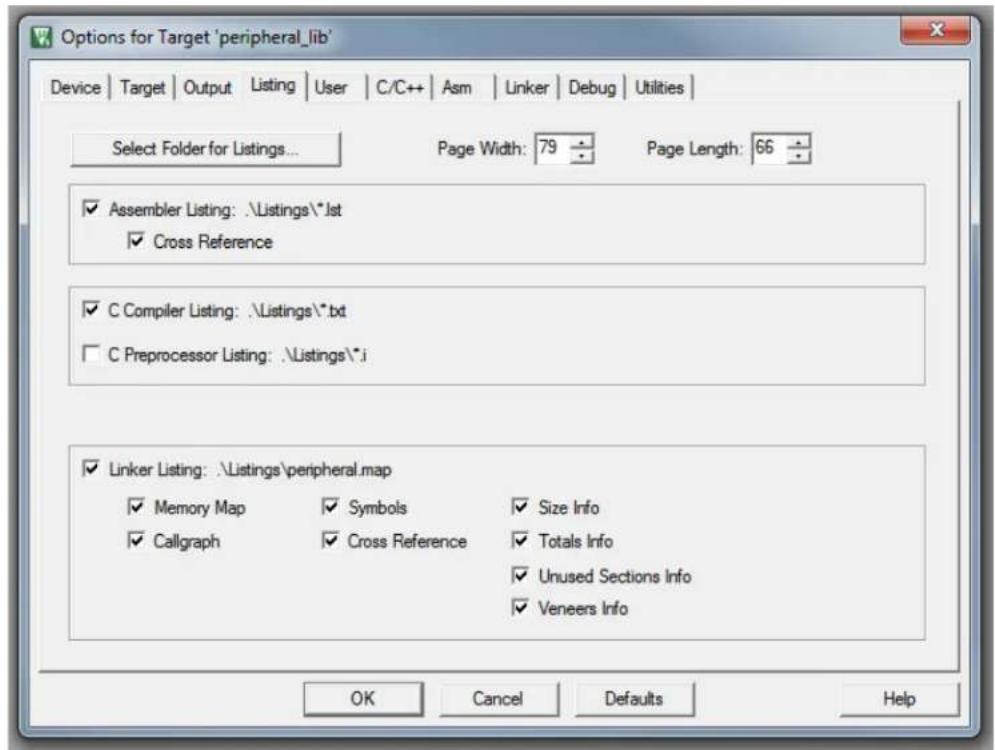
text_image
Options for Target 'peripheral_lib' Device | Target | Output | Listing | User | C/C++ | Asm | Linker | Debug | Utilities | Select Folder for Listings... Page Width: 79 Page Length: 66 ✓ Assembler Listing: \Listings\*.lst ✓ Cross Reference ✓ C Compiler Listing: \Listings\*.txt ☐ C Preprocessor Listing: \Listings\*.i ✓ Linker Listing: \Listings\peripheral.map ✓ Memory Map ✓ Symbols ✓ Size Info ✓ Callgraph ✓ Cross Reference ✓ Totals Info ✓ Unused Sections Info ✓ Veneers Info OK Cancel Defaults Help
text_image
Options for Target 'peripheral_lib' Device | Target | Output | Listing | User | C/C++ | Asm | Linker | Debug | Utilities | Command Items User Command ... Stop on Exi... S... Before Compile C/C++ File Run #1 Not Specified Run #2 Not Specified Before Build/Rebuild Run #1 Not Specified Run #2 Not Specified After Build/Rebuild Run #1 not Specified Run #2 not Specified copy_lib.bat Not Specified Not Specified Run 'After-Build' Conditionally Beep When Complete Start Debugging OK Cancel Defaults Help
text_image
Options for Target 'peripheral_lib' Device | Target | Output | Listing | User | C/C++ | Asm | Linker | Debug | Utilities | Preprocessor Symbols Define: Undefine: Language / Code Generation □ Execute-only Code □ Strict ANSI C Warnings: Optimization: Level 2 (-O2) □ Enum Container always int All Warnings □ Optimize for Time □ Plain Char is Signed □ Thumb Mode □ Split Load and Store Multiple □ Read-Only Position Independent □ No Auto Includes □ One ELF Section per Function □ Read-Write Position Independent □ C99 Mode Include Paths Misc Controls Compiler control string ...common\include;...include;...kernel\skem\source\kemel -c -cpu Cortex-M4 -li -g -O2 -apcs=interwork -split_sections -asm -interleave -asm_dir ".\\Listings\ \" -l...common\include -l...include -l...kernel\skem\source\kemel OK Cancel Defaults Help Options for Target 'peripheral_lib' Device | Target | Output | Listing | User | C/C++ | Asm | Linker | Debug | Utilities | Conditional Assembly Control Symbols Define: Undefine: Language / Code Generation □ Execute-only Code □ Read-Only Position Independent □ Split Load and Store Multiple □ Read-Write Position Independent □ Thumb Mode □ No Warnings □ No Auto Includes Include Paths Misc Controls Assembler control string -cpu Cortex-M4 -li -g -apcs=interwork -l D:\Work\Perforce\pramans_CHE-LT-116169\depot_pcs\FWEng\projects OK Cancel Defaults Help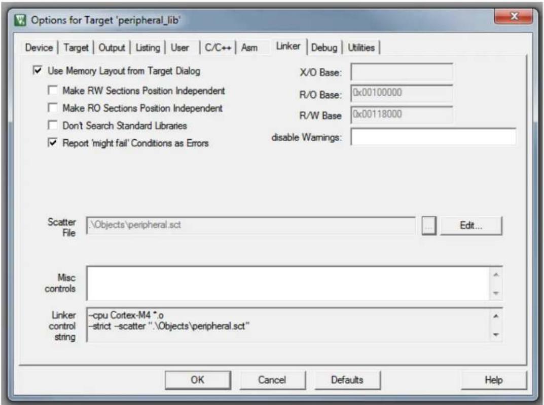
text_image
Options for Target 'peripheral_lib' Device | Target | Output | Listing | User | C/C++ | Asm | Linker | Debug | Utilities | ✓ Use Memory Layout from Target Dialog X/O Base: Make RW Sections Position Independent R/O Base: 0x00100000 Make RO Sections Position Independent R/W Base 0x00118000 Don't Search Standard Libraries ✓ Report 'might fail' Conditions as Errors disable Wamings: Scatter File:\Objects\peripheral.sct Edit... Misc controls Linker control string -cpu Cortex-M4 *.o -strict -scatter ".\Objects\peripheral.sct" OK Cancel Defaults Help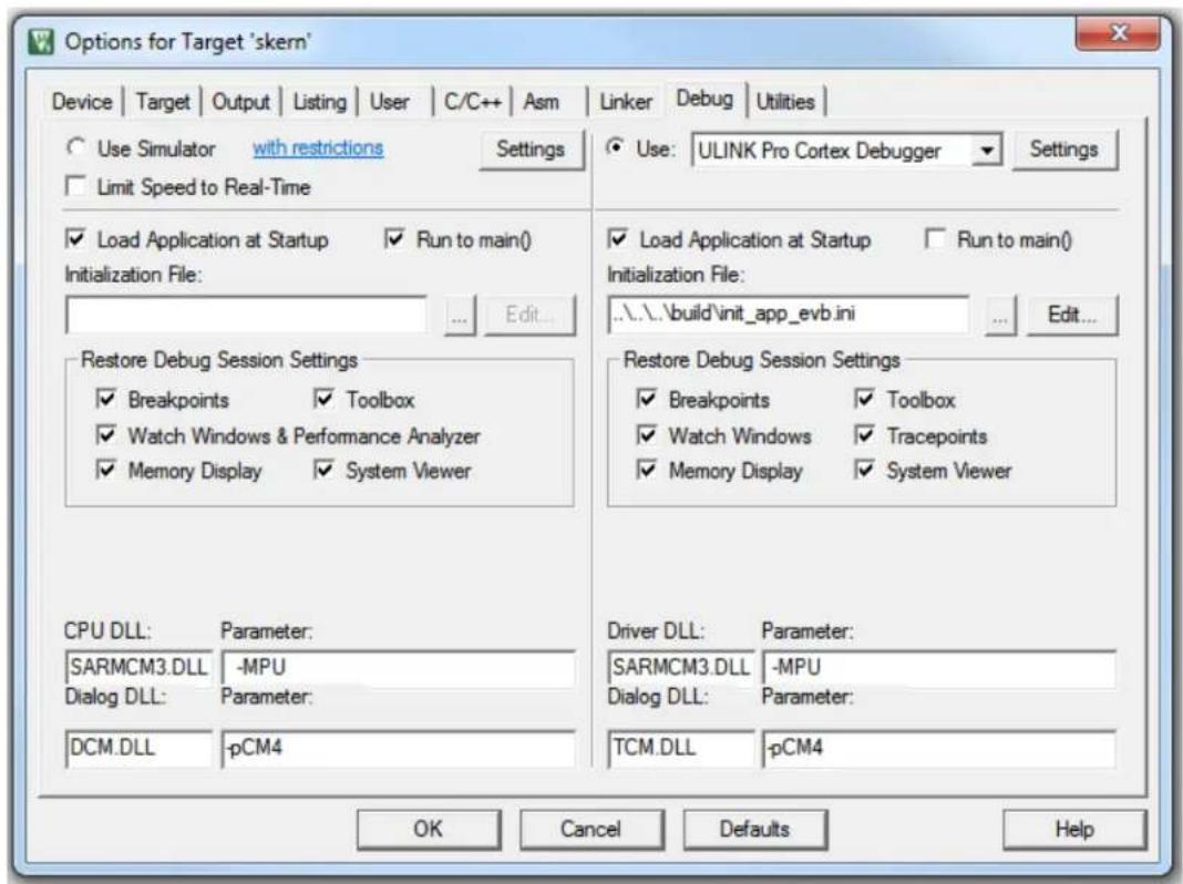
text_image
Options for Target 'skern' Device | Target | Output | Listing | User | C/C++ | Asm | Linker | Debug | Utilities | Use Simulator with restrictions Settings Limit Speed to Real-Time Load Application at Startup Run to main() Initialization File: Edit... Restore Debug Session Settings Breakpoints Toolbox Watch Windows & Performance Analyzer Memory Display System Viewer CPU DLL: Parameter: SARMCM3.DLL -MPU Dialog DLL: Parameter: DCM.DLL -pCM4 Driver DLL: Parameter: SARMCM3.DLL -MPU Dialog DLL: Parameter: TCM.DLL -pCM4 Use: ULINK Pro Cortex Debugger Settings Load Application at Startup Run to main() Initialization File: ..\.\build\init_app_evbi.ini Edit... Restore Debug Session Settings Breakpoints Toolbox Watch Windows Tracepoints Memory Display System Viewer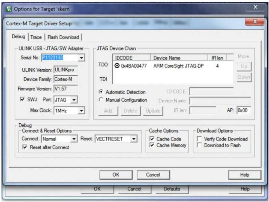
text_image
Options for Target 'skern' Cortex-M Target Driver Setup Debug | Trace | Flash Download | ULINK USB - JTAG/SW Adapter Serial No: P1123133 ULINK Version: ULINKpro Device Family: Cortex-M Firmware Version: V1.57 ✓ SWJ Port: JTAG Max Clock: 1MHz JTAG Device Chain IDCODE Device Name IR len Move TDO 0x4BA00477 ARM CoreSight JTAG-DP 4 Up TDI Automatic Detection ID CODE: Manual Configuration Device Name: Add Delete Update IR len AP: 0x00 Debug Connect & Reset Options Connect: Normal Reset: VECTRESET Cache Options Download Options ✓ Reset after Connect ✓ Cache Code ✓ Cache Memory ✓ Verify Code Download ✓ Download to Flash OK Cancel Help OK Cancel Defaults Help
text_image
Options for Target 'peripheral_lib' Device | Target | Output | Listing | User | C/C++ | Asm | Linker | Debug | Utilities | Configure Flash Menu Command Use Target Driver for Flash Programming Use Debug Driver Settings Update Target before Debugging Init File: Edit... Use External Tool for Flash Programming Command: ... Arguments: Run Independent Configure Image File Processing (FCARM): Output File: Add Output File to Group: common Image Files Root Folder: Generate Listing OK Cancel Defaults Help17.4 PROJECT SETTINGS WITH SKERN PROJECT AS ACTIVE
Note: This section lists only those tabs whose setting differ from that is shown in Section 17.2 "Project Usage".
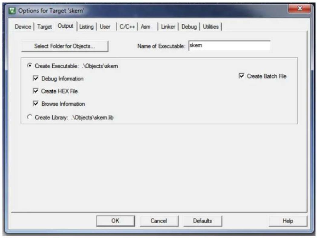
text_image
Options for Target 'skern' Device | Target | Output | Listing | User | C/C++ | Asm | Linker | Debug | Utilities | Select Folder for Objects... Name of Executable: skem Create Executable: \Objects\skem Debug Information Create HEX File Browse Information Create Library: \Objects\skem.lib Create Batch File OK Cancel Defaults Help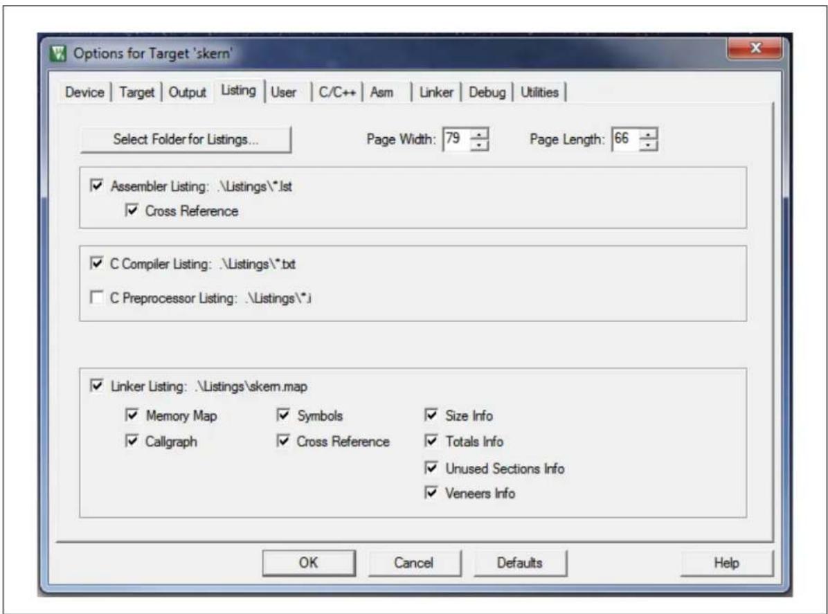
text_image
Options for Target 'skern' Device | Target | Output | Listing | User | C/C++ | Asm | Linker | Debug | Utilities | Select Folder for Listings... Page Width: 79 Page Length: 66 ✓ Assembler Listing: \Listings\*.lst ✓ Cross Reference ✓ C Compiler Listing: \Listings\*.txt ☐ C Preprocessor Listing: \Listings\*.j ✓ Linker Listing: \Listings\skem.map ✓ Memory Map ✓ Symbols ✓ Size Info ✓ Callgraph ✓ Cross Reference ✓ Totals Info ✓ Unused Sections Info ✓ Veneers Info OK Cancel Defaults Help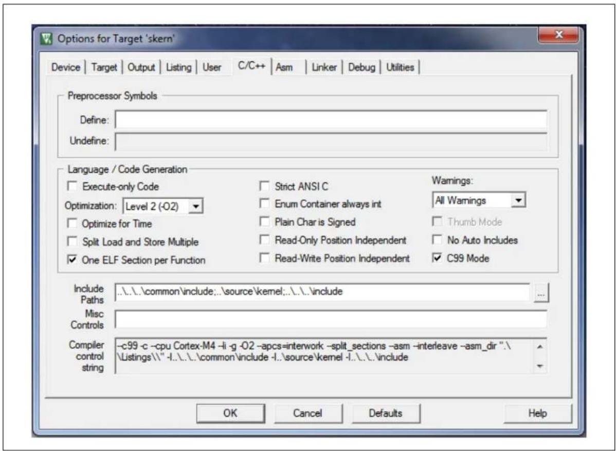
text_image
Options for Target 'skern' Device | Target | Output | Listing | User | C/C++ | Asm | Linker | Debug | Utilities | Preprocessor Symbols Define: Undefine: Language / Code Generation Execute-only Code Optimization: Level 2 (-O2) Optimize for Time Split Load and Store Multiple One ELF Section per Function Strict ANSI C Enum Container always int Plain Char is Signed Read-Only Position Independent Read-Write Position Independent Warnings: All Warnings Thumb Mode No Auto Includes C99 Mode Include Paths Misc Controls -c99 -c -cpu Cortex-M4 -li -g -O2 -apcs=interwork -split_sections -asm -interleave -asm_dir ".\ Listings\" -l..l..l..common\include -l..source\kemei -l..l..l..include Include OK Cancel Defaults Help
text_image
Options for Target 'skern' Device | Target | Output | Listing | User | C/C++ | Asm | Linker | Debug | Utilities | ✓ Use Memory Layout from Target Dialog X/O Base: Make RW Sections Position Independent R/O Base: 0xE0000 Make RO Sections Position Independent R/W Base 0x118000 Don't Search Standard Libraries ✓ Report 'might fail' Conditions as Errors disable Wamings: Scatter File :\Objects\skem.sct Edit... Misc controls ../././target/MEC2016_hw_blks_peripheral.lib Linker control string -cpu Cortex-M4 *.o -strict -scatter ".\Objects\skem.sct" OK Cancel Defaults HelpWorldwide Sales and Service
AMERICAS
Corporate Office
2355 West Chandler Blvd.
Chandler, AZ 85224-6199
Tel: 480-792-7200
Fax: 480-792-7277
Technical Support:
http://www.microchip.com/
support
Web Address:
www.microchip.com
Atlanta
Duluth, GA
Tel: 678-957-9614
Fax: 678-957-1455
Austin, TX
Tel: 512-257-3370
Boston
Westborough, MA
Tel: 774-760-0087
Fax: 774-760-0088
Chicago
Itasca, IL
Tel: 630-285-0071
Fax: 630-285-0075
Dallas
Addison, TX
Tel: 972-818-7423
Fax: 972-818-2924
Detroit
Novi, MI
Tel: 248-848-4000
Houston, TX
Tel: 281-894-5983
Indianapolis
Noblesville, IN
Tel: 317-773-8323
Fax: 317-773-5453
Tel: 317-536-2380
Los Angeles
Mission Viejo, CA
Tel: 949-462-9523
Fax: 949-462-9608
Tel: 951-273-7800
Raleigh, NC
Tel: 919-844-7510
New York, NY
Tel: 631-435-6000
San Jose, CA
Tel: 408-735-9110
Tel: 408-436-4270
Canada - Toronto
Tel: 905-695-1980
Fax: 905-695-2078
ASIA/PACIFIC
Asia Pacific Office
Suites 3707-14, 37th Floor
Tower 6, The Gateway
Harbour City, Kowloon
Hong Kong
Tel: 852-2943-5100
Fax: 852-2401-3431
Australia - Sydney
Tel: 61-2-9868-6733
Fax: 61-2-9868-6755
China - Beijing
Tel: 86-10-8569-7000
Fax: 86-10-8528-2104
China - Chengdu
Tel: 86-28-8665-551
Fax: 86-28-8665-7889
China - Chongqing
Tel: 86-23-8980-9588
Fax: 86-23-8980-9500
China - Dongguan
Tel: 86-769-8702-9880
China - Guangzhou
Tel: 86-20-8755-8029
China - Hangzhou
Tel: 86-571-8792-8115
Fax: 86-571-8792-8116
China - Hong Kong SAR
Tel: 852-2943-5100
Fax: 852-2401-3431
China - Nanjing
Tel: 86-25-8473-2460
Fax: 86-25-8473-2470
China - Qingdao
Tel: 86-532-8502-7355
Fax: 86-532-8502-7205
China - Shanghai
Tel: 86-21-3326-8000
Fax: 86-21-3326-8021
China - Shenyang
Tel: 86-24-2334-2829
Fax: 86-24-2334-2393
China - Shenzhen
Tel: 86-755-8864-2200
Fax: 86-755-8203-1760
China - Wuhan
Tel: 86-27-5980-5300
Fax: 86-27-5980-5118
China - Xian
Tel: 86-29-8833-7252
Fax: 86-29-8833-7256
ASIA/PACIFIC
China - Xiamen
Tel: 86-592-2388138
Fax: 86-592-2388130
China - Zhuhai
Tel: 86-756-3210040
Fax: 86-756-3210049
India - Bangalore
Tel: 91-80-3090-4444
Fax: 91-80-3090-4123
India - New Delhi
Tel: 91-11-4160-8631
Fax: 91-11-4160-8632
India - Pune
Tel: 91-20-3019-1500
Japan - Osaka
Tel: 81-6-6152-7160
Fax: 81-6-6152-9310
Japan - Tokyo
Tel: 81-3-6880-3770
Fax: 81-3-6880-3771
Korea - Daegu
Tel: 82-53-744-4301
Fax: 82-53-744-4302
Korea - Seoul
Tel: 82-2-554-7200
Fax: 82-2-558-5932 or
82-2-558-5934
Malaysia - Kuala Lumpur
Tel: 60-3-6201-9857
Fax: 60-3-6201-9859
Malaysia - Penang
Tel: 60-4-227-8870
Fax: 60-4-227-4068
Philippines - Manila
Tel: 63-2-634-9065
Fax: 63-2-634-9069
Singapore
Tel: 65-6334-8870
Fax: 65-6334-8850
Taiwan - Hsin Chu
Tel: 886-3-5778-366
Fax: 886-3-5770-955
Taiwan - Kaohsiung
Tel: 886-7-213-7830
Taiwan - Taipei
Tel: 886-2-2508-8600
Fax: 886-2-2508-0102
Thailand - Bangkok
Tel: 66-2-694-1351
Fax: 66-2-694-1350
EUROPE
Austria - Wels
Tel: 43-7242-2244-39
Fax: 43-7242-2244-393
Denmark - Copenhagen
Tel: 45-4450-2828
Fax: 45-4485-2829
Finland - Espoo
Tel: 358-9-4520-820
France - Paris
Tel: 33-1-69-53-63-20
Fax: 33-1-69-30-90-79
France - Saint Cloud
Tel: 33-1-30-60-70-00
Germany - Garching
Tel: 49-8931-9700
Germany - Haan
Tel: 49-2129-3766400
Germany - Heilbronn
Tel: 49-7131-67-3636
Germany - Karlsruhe
Tel: 49-721-625370
Germany - Munich
Tel: 49-89-627-144-0
Fax: 49-89-627-144-44
Germany - Rosenheim
Tel: 49-8031-354-560
Israel - Ra'anana
Tel: 972-9-744-7705
Italy - Milan
Tel: 39-0331-742611
Fax: 39-0331-466781
Italy - Padova
Tel: 39-049-7625286
Netherlands - Drunen
Tel: 31-416-690399
Fax: 31-416-690340
Norway - Trondheim
Tel: 47-7289-7561
Poland - Warsaw
Tel: 48-22-3325737
Romania - Bucharest
Tel: 40-21-407-87-50
Spain - Madrid
Tel: 34-91-708-08-90
Fax: 34-91-708-08-91
Sweden - Gothenberg
Tel: 46-31-704-60-40
Sweden - Stockholm
Tel: 46-8-5090-4654
UK - Wokingham
Tel: 44-118-921-5800
Fax: 44-118-921-5820