2AMXM50M3V1B - Air Conditioning DAIKIN - Free user manual and instructions
Find the device manual for free 2AMXM50M3V1B DAIKIN in PDF.

User questions about 2AMXM50M3V1B DAIKIN
0 question about this device. Answer the ones you know or ask your own.
Ask a new question about this device
Download the instructions for your Air Conditioning in PDF format for free! Find your manual 2AMXM50M3V1B - DAIKIN and take your electronic device back in hand. On this page are published all the documents necessary for the use of your device. 2AMXM50M3V1B by DAIKIN.
USER MANUAL 2AMXM50M3V1B DAIKIN
Installer reference guide R32 Split series

natural_image
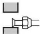
Illustration of a rectangular industrial air conditioning unit with cooling fins and ventilation slots (no text or symbols)2MXM40M4V1B
2MXM50M3V1B9
2AMXM40M4V1B
2AMXM50M4V1B
2AMXF40A2V1B
2AMXF50A2V1B
2MXF40A2V1B
2MXF50A2V1B
2MXM40N2V1B
2MXM50N2V1B
Table of contents
1 About the documentation 4
1.1 About this document 4
2 General safety precautions 5
2.1 About the documentation 5
2.1.1 Meaning of warnings and symbols 5
2.2 For the installer 6
2.2.1 General 6
2.2.2 Installation site 7
2.2.3 Refrigerant — in case of R410A or R32.... 11
2.2.4 Brine 12
2.2.5 Water 13
2.2.6 Electrical 13
3 Specific installer safety instructions 16
4 About the box 22
4.1 Overview: About the box.... 22
4.2 Outdoor unit 22
4.2.1 To unpack the outdoor unit 22
4.2.2 To remove the accessories from the outdoor unit.... 23
5 About the unit 25
5.1 Overview: About the unit 25
5.2 Identification 25
5.2.1 Identification label: Outdoor unit 25
6 Unit installation 26
6.1 Preparing the installation site.... 26
6.1.1 Installation site requirements of the outdoor unit 27
6.1.2 Additional installation site requirements of the outdoor unit in cold climates.... 29
6.2 Opening the unit 30
6.2.1 About opening the unit 30
6.2.2 To open the outdoor unit 30
6.3 Mounting the outdoor unit 30
6.3.1 About mounting the outdoor unit 30
6.3.2 Precautions when mounting the outdoor unit 31
6.3.3 To provide the installation structure 31
6.3.4 To install the outdoor unit 32
6.3.5 To provide drainage.... 32
6.3.6 To prevent the outdoor unit from falling over 33
7 Piping installation 34
7.1 Preparing refrigerant piping 34
7.1.1 Refrigerant piping requirements.... 34
7.1.2 Refrigerant piping insulation 35
7.1.3 Refrigerant piping length and height difference 35
7.2 Connecting the refrigerant piping 36
7.2.1 About connecting the refrigerant piping 36
7.2.2 Precautions when connecting the refrigerant piping 36
7.2.3 Guidelines when connecting the refrigerant piping.... 38
7.2.4 Pipe bending guidelines 38
7.2.5 To flare the pipe end 38
7.2.6 Connections between outdoor and indoor unit using reducers 39
7.2.7 Using the stop valve and service port 40
7.2.8 To connect the refrigerant piping to the outdoor unit 42
7.3 Checking the refrigerant piping 42
7.3.1 About checking the refrigerant piping 42
7.3.2 Precautions when checking the refrigerant piping.... 43
7.3.3 To check for leaks 43
7.3.4 To perform vacuum drying.... 44
8 Charging refrigerant 46
8.1 About charging refrigerant 46
8.2 About the refrigerant 47
8.3 Precautions when charging refrigerant.... 48
8.4 To determine the additional refrigerant amount 48
8.5 To determine the complete recharge amount 48
8.6 To charge additional refrigerant 48
8.7 To fix the fluorinated greenhouse gases label 49
9 Electrical installation 50
9.1 About connecting the electrical wiring 50
9.1.1 Precautions when connecting the electrical wiring.... 50
9.1.2 Guidelines when connecting the electrical wiring.... 52
9.1.3 Specifications of standard wiring components.... 53
9.2 To connect the electrical wiring to the outdoor unit.... 53
10 Finishing the outdoor unit installation 55
10.1 To finish the outdoor unit installation.... 55
10.2 To close the outdoor unit 55
11 Configuration 56
11.1 About ECONO mode prohibition setting.... 56
11.1.1 To turn on ECONO mode prohibition setting 56
11.2 About night quiet mode.... 57
11.2.1 To turn on the night quiet mode.... 57
11.3 About heat mode lock 57
11.3.1 To turn on heat mode lock 57
11.4 About standby electricity saving function 58
11.4.1 To turn on standby electricity saving function 58
12 Commissioning 59
12.1 Overview: Commissioning 59
12.2 Precautions when commissioning 59
12.3 Checklist before commissioning 59
12.4 Checklist during commissioning 60
12.5 Trial operation and testing 60
12.5.1 To perform a test run 60
12.6 Starting up the outdoor unit.... 61
13 Hand-over to the user 62
14 Maintenance and service 63
14.1 Overview: Maintenance and service 63
14.2 Maintenance safety precautions 63
14.3 Checklist for yearly maintenance of the outdoor unit 63
14.4 About the compressor 64
15 Troubleshooting 65
15.1 Overview: Troubleshooting 65
15.2 Precautions when troubleshooting 65
15.3 Solving problems based on symptoms.... 65
15.3.1 Symptom: Indoor units fall, vibrate or make noise 65
15.3.2 Symptom: The unit is NOT heating or cooling as expected.... 66
15.3.3 Symptom: Water leakage 66
15.3.4 Symptom: Electrical leakage 66
15.3.5 Symptom: Unit does NOT function or burn damage.... 66
15.4 Solving problems based on LED behaviour 66
15.4.1 Fault diagnosis using LED on outdoor unit PCB 66
16 Disposal 68
16.1 Overview: Disposal.... 68
16.2 To pump down 68
16.3 To start and stop forced cooling.... 69
16.3.1 To start and stop forced cooling using the indoor unit ON/OFF switch 69
16.3.2 To start and stop forced cooling using the indoor unit user interface 69
17 Technical data 70
17.1 Wiring diagram.... 70
17.1.1 Unified wiring diagram legend 70
17.2 Piping diagram: Outdoor unit 72
18 Glossary 74
1 About the documentation
1.1 About this document
Target audience
Authorised installers

INFORMATION
This appliance is intended to be used by expert or trained users in shops, in light industry, and on farms, or for commercial and household use by lay persons.

WARNING
Make sure installation, servicing, maintenance, repair and applied materials follow the instructions from Daikin and, in addition, comply with applicable legislation and are performed by qualified persons only. In Europe and areas where IEC standards apply, EN/IEC 60335-2-40 is the applicable standard.

INFORMATION
This document only describes installation instructions specific to the outdoor unit. For installation of the indoor unit (mounting the indoor unit, connecting the refrigerant piping to the indoor unit, connecting the electrical wiring to the indoor unit ...), see the installation manual of the indoor unit.
Documentation set
This document is part of a documentation set. The complete set consists of:
- General safety precautions:
- Safety instructions that you MUST read before installing
- Format: Paper (in the box of the outdoor unit)
- Outdoor unit installation manual:
- Installation instructions
- Format: Paper (in the box of the outdoor unit)
- Installer reference guide:
- Preparation of the installation, reference data,...
- Format: Digital files on http://www.daikineurope.com/support-and-manuals/product-information/
Latest revisions of the supplied documentation may be available on the regional Daikin website or via your dealer.
The original documentation is written in English. All other languages are translations.
Technical engineering data
- A subset of the latest technical data is available on the regional Daikin website (publicly accessible).
- The full set of latest technical data is available on the Daikin Business Portal (authentication required).
2 General safety precautions
2.1 About the documentation
- The original documentation is written in English. All other languages are translations.
- The precautions described in this document cover very important topics, follow them carefully.
- The installation of the system, and all activities described in the installation manual and in the installer reference guide MUST be performed by an authorised installer.
2.1.1 Meaning of warnings and symbols

DANGER
Indicates a situation that results in death or serious injury.

DANGER: RISK OF ELECTROCUTION
Indicates a situation that could result in electrocution.

DANGER: RISK OF BURNING/SCALDING
Indicates a situation that could result in burning/scalding because of extreme hot or cold temperatures.

DANGER: RISK OF EXPLOSION
Indicates a situation that could result in explosion.

WARNING
Indicates a situation that could result in death or serious injury.

WARNING: FLAMMABLE MATERIAL

CAUTION
Indicates a situation that could result in minor or moderate injury.

NOTICE
Indicates a situation that could result in equipment or property damage.

INFORMATION
Indicates useful tips or additional information.
Symbols used on the unit:
2 | General safety precautions
| Symbol Explanation | |
 | Before installation, read the installation and operation manual, and the wiring instruction sheet. |
 | Before performing maintenance and service tasks, read the service manual. |
 | For more information, see the installer and user reference guide. |
 | The unit contains rotating parts. Be careful when servicing or inspecting the unit. |
Symbols used in the documentation:
| Symbol Explanation | |
| Indicates a figure title or a reference to it.Example: "1-3 Figure title" means "Figure 3 in chapter 1". | |
| Indicates a table title or a reference to it.Example: "1-3 Table title" means "Table 3 in chapter 1". | |
2.2 For the installer
2.2.1 General
If you are NOT sure how to install or operate the unit, contact your dealer.

DANGER: RISK OF BURNING/SCALDING
- Do NOT touch the refrigerant piping, water piping or internal parts during and immediately after operation. It could be too hot or too cold. Give it time to return to normal temperature. If you must touch it, wear protective gloves.
- Do NOT touch any accidental leaking refrigerant.

WARNING
Improper installation or attachment of equipment or accessories could result in electrical shock, short-circuit, leaks, fire or other damage to the equipment. Only use accessories, optional equipment and spare parts made or approved by Daikin.

WARNING
Make sure installation, testing and applied materials comply with applicable legislation (on top of the instructions described in the Daikin documentation).

CAUTION
Wear adequate personal protective equipment (protective gloves, safety glasses,...) when installing, maintaining or servicing the system.

WARNING
Tear apart and throw away plastic packaging bags so that nobody, especially children, can play with them. Possible risk: suffocation.

WARNING
Provide adequate measures to prevent that the unit can be used as a shelter by small animals. Small animals that make contact with electrical parts can cause malfunctions, smoke or fire.

CAUTION
Do NOT touch the air inlet or aluminium fins of the unit.

CAUTION
- Do NOT place any objects or equipment on top of the unit.
- Do NOT sit, climb or stand on the unit.

NOTICE
Works executed on the outdoor unit are best done under dry weather conditions to avoid water ingress.
In accordance with the applicable legislation, it might be necessary to provide a logbook with the product containing at least: information on maintenance, repair work, results of tests, stand-by periods,...
Also, at least, following information MUST be provided at an accessible place at the product:
- Instructions for shutting down the system in case of an emergency
- Name and address of fire department, police and hospital
- Name, address and day and night telephone numbers for obtaining service. In Europe, EN378 provides the necessary guidance for this logbook.
2.2.2 Installation site
- Provide sufficient space around the unit for servicing and air circulation.
- Make sure the installation site withstands the weight and vibration of the unit.
■ Make sure the area is well ventilated. Do NOT block any ventilation openings. - Make sure the unit is level.
Do NOT install the unit in the following places: - In potentially explosive atmospheres.
- In places where there is machinery that emits electromagnetic waves. Electromagnetic waves may disturb the control system, and cause malfunction of the equipment.
- In places where there is a risk of fire due to the leakage of flammable gases (example: thinner or gasoline), carbon fibre, ignitable dust.
- In places where corrosive gas (example: sulphurous acid gas) is produced. Corrosion of copper pipes or soldered parts may cause the refrigerant to leak.
Instructions for equipment using R32 refrigerant

WARNING: FLAMMABLE MATERIAL
The refrigerant inside this unit is mildly flammable.

WARNING: MILDLY FLAMMABLE MATERIAL
The refrigerant inside this unit is mildly flammable.

WARNING
- Do NOT pierce or burn.
- Do NOT use means to accelerate the defrosting process or to clean the equipment, other than those recommended by the manufacturer.
- Be aware that R32 refrigerant does NOT contain an odour.

WARNING
The appliance shall be stored so as to prevent mechanical damage and in a well-ventilated room without continuously operating ignition sources (example: open flames, an operating gas appliance or an operating electric heater) and have a room size as specified below.

WARNING
Make sure installation, servicing, maintenance and repair comply with instructions from Daikin and with applicable legislation (for example national gas regulation) and are executed only by authorised persons.

WARNING
If one or more rooms are connected to the unit using a duct system, make sure:
- there are no operating ignition sources (example: open flames, an operating gas appliance or an operating electric heater) in case the floor area is less than the minimum floor area A (m^2) .
- no auxiliary devices, which may be a potential ignition source, are installed in the duct work (example: hot surfaces with a temperature exceeding 700°C and electric switching device);
- only auxiliary devices approved by the manufacturer are used in the duct work;
- air inlet AND outlet are connected directly to the same room by ducting. Do NOT use spaces such as a false ceiling as a duct for the air inlet or outlet.

NOTICE
- Precautions shall be taken to avoid excessive vibration or pulsation to refrigeration piping.
- Protection devices, piping and fittings shall be protected as far as possible against adverse environmental effects.
■ Provision shall be made for expansion and contraction of long runs of piping. - Piping in refrigerating systems shall be designed and installed such as to minimise the likelihood of hydraulic shock damaging the system.
- The indoor equipment and pipes shall be securely mounted and guarded such that accidental rupture of equipment or pipes cannot occur from events such as moving furniture or reconstruction activities.

CAUTION
Do NOT use potential sources of ignition in searching for or detection of refrigerant leaks.

NOTICE
- Do NOT re-use joints which have been used already.
- Joints made in installation between parts of refrigerant system shall be accessible for maintenance purposes.
Installation space requirements

WARNING
If appliances contain R32 refrigerant, the floor area of the room in which the appliances are installed, operated and stored MUST be larger than the minimum floor area defined in table below A (m ^2 ). This applies to:
- Indoor units without a refrigerant leakage sensor; in case of indoor units with refrigerant leakage sensor, consult the installation manual
- Outdoor units installed or stored indoors (e.g. winter garden, garage, machinery room)
- Pipework in unventilated spaces

NOTICE
- Pipework shall be protected from physical damage.
- Installation of pipework shall be kept to a minimum.
To determine the minimum floor area
1 Determine the total refrigerant charge in the system (= factory refrigerant charge 0+ additional refrigerant amount charged).

text_image
Contains fluorinated greenhouse gases R32 GWP: xxx ① = kg ② = kg ① + ② = kg GWP × kg / 1000 = CO₂ eq2 Determine which graph or table to use.
- For indoor units: Is the unit ceiling-mounted, wall-mounted or floor-standing?
- For outdoor units installed or stored indoors, and field piping in unventilated spaces, this depends on the installation height:
| If the installation height is... Then use | the graph or table for... |
| <1.8 m Floor-standing units | |
| 1.8≤x<2.2 m Wall-mounted units | |
| ≥2.2 m Ceiling-mounted units |
3 Use the graph or table to determine the minimum floor area.

line
| m (kg) | Floor Standing unit (m²) | Wall-mounted unit (m²) | Ceiling-mounted unit (m²) | | ------ | ------------------------ | ---------------------- | ------------------------- | | 1.8 | 30 | 10 | 10 | | 2.2 | 40 | 15 | 15 | | 2.6 | 50 | 20 | 20 | | 3.0 | 60 | 25 | 25 | | 3.4 | 70 | 30 | 30 | | 3.8 | 80 | 35 | 35 | | 4.2 | 90 | 40 | 40 | | 4.6 | 100 | 45 | 45 | | 5.0 | 110 | 50 | 50 | | 5.4 | 120 | 55 | 55 | | 5.8 | 130 | 60 | 60 | | 6.2 | 140 | 65 | 65 | | 6.6 | 150 | 70 | 70 | | 7.0 | 160 | 75 | 75 | | 7.4 | 170 | 80 | 80 | | 7.8 | 180 | 85 | 85 | | 8.0 | 190 | 90 | 90 || Ceiling-mounted unit(a) | Wall-mounted unit(b) | Floor-standing unit(c) |
| m (kg) — Amin (m2) | m (kg) — Amin (m2) | m (kg) — Amin (m2) |
| ≤1.842 — | ≤1.842 — | ≤1.842 — |
| 1.8433-64 | 1.8434-45 | 1.84328-9 |
| 2.03-95 | 2.04-83 | 2.034-0 |
| 2.24-34 | 2.25-31 | 2.241-2 |
| 2.44-74 | 2.45-79 | 2.449-0 |
| 2.65-13 | 2.66-39 | 2.657-5 |
| 2.85-53 | 2.87-41 | 2.866-7 |
| 3.05-92 | 3.08-51 | 3.076-6 |
| 3.26-48 | 3.29-68 | 3.287-2 |
| 3.47-32 | 3.410-9 | 3.498-4 |
| 3.68-20 | 3.612-3 | 3.6110- |
| 3.89-14 | 3.813-7 | 3.8123- |
| 4.010-1 | 4.015-1 | 4.0136- |
| 4.211-2 | 4.216-7 | 4.2150- |
| 4.412-3 | 4.418-3 | 4.4165- |
| 4.613-4 | 4.620-0 | 4.6180- |
| 4.814-6 | 4.821-8 | 4.8196- |
| 5.015-8 | 5.023-6 | 5.0213- |
| 5.217-1 | 5.225-6 | 5.2230- |
| 5.418-5 | 5.427-6 | 5.4248- |
| 5.619-9 | 5.629-7 | 5.6267- |
| 5.821-3 | 5.831-8 | 5.8286- |
| 6.022-8 | 6.034-0 | 6.0306- |
| 6.224-3 | 6.236-4 | 6.2327- |
| 6.425-9 | 6.438-7 | 6.4349- |
| 6.627-6 | 6.641-2 | 6.6371- |
| 6.829-3 | 6.843-7 | 6.8394- |
| 7.031-0 | 7.046-3 | 7.0417- |
| 7.232-8 | 7.249-0 | 7.2441- |
| 7.434-7 | 7.451-8 | 7.4466- |
| 7.636-6 | 7.654-6 | 7.6492- |
| 7.838-5 | 7.857-5 | 7.8518- |
| 7.95640-1 | 7.95659-9 | 7.956539- |
m Total refrigerant charge in the system
A_min Minimum floor area
(a) Ceiling-mounted unit (= Ceiling-mounted unit)
(b) Wall-mounted unit (= Wall-mounted unit)
(c) Floor-standing unit (= Floor-standing unit)
2.2.3 Refrigerant — in case of R410A or R32
If applicable. See the installation manual or installer reference guide of your application for more information.

NOTICE
Make sure refrigerant piping installation complies with applicable legislation. In Europe, EN378 is the applicable standard.

NOTICE
Make sure the field piping and connections are NOT subjected to stress.

WARNING
During tests, NEVER pressurize the product with a pressure higher than the maximum allowable pressure (as indicated on the nameplate of the unit).

WARNING
Take sufficient precautions in case of refrigerant leakage. If refrigerant gas leaks, ventilate the area immediately. Possible risks:
- Excessive refrigerant concentrations in a closed room can lead to oxygen deficiency.
- Toxic gas might be produced if refrigerant gas comes into contact with fire.

DANGER: RISK OF EXPLOSION
Pump down – Refrigerant leakage. If you want to pump down the system, and there is a leak in the refrigerant circuit:
- Do NOT use the unit's automatic pump down function, with which you can collect all refrigerant from the system into the outdoor unit. Possible consequence: Self-combustion and explosion of the compressor because of air going into the operating compressor.
- Use a separate recovery system so that the unit's compressor does NOT have to operate.

WARNING
ALWAYS recover the refrigerant. Do NOT release them directly into the environment. Use a vacuum pump to evacuate the installation.

NOTICE
After all the piping has been connected, make sure there is no gas leak. Use nitrogen to perform a gas leak detection.

NOTICE
- To avoid compressor breakdown, do NOT charge more than the specified amount of refrigerant.
- When the refrigerant system is to be opened, refrigerant MUST be treated according to the applicable legislation.

WARNING
Make sure there is no oxygen in the system. Refrigerant may only be charged after performing the leak test and the vacuum drying.
Possible consequence: Self-combustion and explosion of the compressor because of oxygen going into the operating compressor.
- In case recharge is required, see the nameplate of the unit. It states the type of refrigerant and necessary amount.
- The unit is factory charged with refrigerant and depending on pipe sizes and pipe lengths some systems require additional charging of refrigerant.
- Only use tools exclusively for the refrigerant type used in the system, this to ensure pressure resistance and prevent foreign materials from entering into the system.
- Charge the liquid refrigerant as follows:
| If Then | |
| A siphon tube is present(i.e., the cylinder is marked with "Liquid filling siphon attached") | Charge with the cylinder upright. |
| A siphon tube is NOT present Charge with the cylinder upside down. |
- Open refrigerant cylinders slowly.
- Charge the refrigerant in liquid form. Adding it in gas form may prevent normal operation.

CAUTION
When the refrigerant charging procedure is done or when pausing, close the valve of the refrigerant tank immediately. If the valve is NOT closed immediately, remaining pressure might charge additional refrigerant. Possible consequence: Incorrect refrigerant amount.
2.2.4 Brine
If applicable. See the installation manual or installer reference guide of your application for more information.

WARNING
The selection of the brine MUST be in accordance with the applicable legislation.

WARNING
Take sufficient precautions in case of brine leakage. If brine leaks, ventilate the area immediately and contact your local dealer.

WARNING
The ambient temperature inside the unit can get much higher than that of the room, e.g. 70°C. In case of a brine leak, hot parts inside the unit can create a hazardous situation.

WARNING
The use and installation of the application MUST comply with the safety and environmental precautions specified in the applicable legislation.
2.2.5 Water
If applicable. See the installation manual or installer reference guide of your application for more information.

NOTICE
Make sure water quality complies with EU directive 98/83 EC.
2.2.6 Electrical

DANGER: RISK OF ELECTROCUTION
- Turn OFF all power supply before removing the switch box cover, connecting electrical wiring or touching electrical parts.
- Disconnect the power supply for more than 10 minutes, and measure the voltage at the terminals of main circuit capacitors or electrical components before servicing. The voltage MUST be less than 50 V DC before you can touch electrical components. For the location of the terminals, see the wiring diagram.
- Do NOT touch electrical components with wet hands.
- Do NOT leave the unit unattended when the service cover is removed.

WARNING
If NOT factory installed, a main switch or other means for disconnection, having a contact separation in all poles providing full disconnection under overvoltage category III condition, MUST be installed in the fixed wiring.

WARNING
ONLY use copper wires.
■ Make sure the field wiring complies with the applicable legislation.
- All field wiring MUST be performed in accordance with the wiring diagram supplied with the product.
- NEVER squeeze bundled cables and make sure they do NOT come in contact with the piping and sharp edges. Make sure no external pressure is applied to the terminal connections.
- Make sure to install earth wiring. Do NOT earth the unit to a utility pipe, surge absorber, or telephone earth. Incomplete earth may cause electrical shock.
- Make sure to use a dedicated power circuit. NEVER use a power supply shared by another appliance.
- Make sure to install the required fuses or circuit breakers.
- Make sure to install an earth leakage protector. Failure to do so may cause electrical shock or fire.
- When installing the earth leakage protector, make sure it is compatible with the inverter (resistant to high frequency electric noise) to avoid unnecessary opening of the earth leakage protector.

CAUTION
- When connecting the power supply: connect the earth cable first, before making the current-carrying connections.
- When disconnecting the power supply: disconnect the current-carrying cables first, before separating the earth connection.
- The length of the conductors between the power supply stress relief and the terminal block itself must be as such that the current-carrying wires are tautened before the earth wire is in case the power supply is pulled loose from the stress relief.

NOTICE
Precautions when laying power wiring:
- Do NOT connect wiring of different thicknesses to the power terminal block (slack in the power wiring may cause abnormal heat).
- When connecting wiring which is the same thickness, do as shown in the figure above.
- For wiring, use the designated power wire and connect firmly, then secure to prevent outside pressure being exerted on the terminal board.
- Use an appropriate screwdriver for tightening the terminal screws. A screwdriver with a small head will damage the head and make proper tightening impossible.
- Over-tightening the terminal screws may break them.
Install power cables at least 1 m away from televisions or radios to prevent interference. Depending on the radio waves, a distance of 1 m may not be sufficient.

WARNING
■ After finishing the electrical work, confirm that each electrical component and terminal inside the electrical components box is connected securely.
■ Make sure all covers are closed before starting up the unit.

NOTICE
Only applicable if the power supply is three-phase, and the compressor has an ON/OFF starting method.
If there exists the possibility of reversed phase after a momentary black out and the power goes on and off while the product is operating, attach a reversed phase protection circuit locally. Running the product in reversed phase can break the compressor and other parts.
3 Specific installer safety instructions
Always observe the following safety instructions and regulations.
Unit installation (see "6 Unit installation" [▶ 26])

WARNING
Installation shall be done by an installer, the choice of materials and installation shall comply with the applicable legislation. In Europe, EN378 is the applicable standard.
Installation site (see "6.1 Preparing the installation site" [▶ 26])

CAUTION
- Check if the installation location can support the unit's weight. Poor installation is hazardous. It can also cause vibrations or unusual operating noise.
■ Provide sufficient service space. - Do NOT install the unit so that it is in contact with a ceiling or a wall, as this may cause vibrations.

WARNING
The appliance shall be stored in a room without continuously operating ignition sources (example: open flames, an operating gas appliance or an operating electric heater).
Opening the unit (see "6.2 Opening the unit" [▶ 30])

DANGER: RISK OF ELECTROCUTION
Do NOT leave the unit unattended when the service cover is removed.

DANGER: RISK OF BURNING/SCALDING

DANGER: RISK OF ELECTROCUTION
Connecting the refrigerant piping (see "7.2 Connecting the refrigerant piping" [▶ 36])

CAUTION
- No brazing or welding on site for units with R32 refrigerant charge during shipment.
During installation of the refrigeration system, joining of parts with at least one part charged shall be performed taking into account the following requirements:
→ inside occupied spaces non permanent joints are not allowed for R32 refrigerant except for site made joints directly connecting the indoor unit to piping. Site made joints directly connecting piping to indoor units shall be of non permanent type.

CAUTION
Do NOT connect the embedded branch piping and the outdoor unit when only carrying out piping work without connecting the indoor unit in order to add another indoor unit later.

WARNING
- Only use R32 as refrigerant. Other substances may cause explosions and accidents.
- R32 contains fluorinated greenhouse gases. Its global warming potential (GWP) value is 675. Do NOT vent these gases into the atmosphere.
- When charging refrigerant, ALWAYS use protective gloves and safety glasses.

CAUTION
- Do NOT use mineral oil on flared part.
- Do NOT reuse piping from previous installations.
- NEVER install a drier to this R32 unit to guarantee its lifetime. The drying material may dissolve and damage the system.

CAUTION
- Use the flare nut fixed to the unit.
- To prevent gas leakage, apply refrigeration oil only to the inside of the flare. Use refrigeration oil for R32.
- Do NOT reuse joints.

WARNING
Connect the refrigerant piping securely before running the compressor. If the refrigerant piping is NOT connected and the stop valve is open when the compressor is run, air will be sucked in. This will cause abnormal pressure in the refrigeration cycle, which may result in equipment damage and even injury.

CAUTION
- Incomplete flaring may cause refrigerant gas leakage.
- Do NOT re-use flares. Use new flares to prevent refrigerant gas leakage.
- Use flare nuts that are included with the unit. Using different flare nuts may cause refrigerant gas leakage.
Charging refrigerant (see "8 Charging refrigerant" [▶ 46])

WARNING: FLAMMABLE MATERIAL
The refrigerant inside this unit is mildly flammable.

WARNING
The refrigerant inside the unit is mildly flammable, but normally does NOT leak. If the refrigerant leaks in the room and comes in contact with fire from a burner, a heater, or a cooker, this may result in fire, or the formation of a harmful gas.
Turn off any combustible heating devices, ventilate the room, and contact the dealer where you purchased the unit.
Do NOT use the unit until a service person confirms that the part from which the refrigerant leaked has been repaired.

WARNING
NEVER directly touch any accidental leaking refrigerant. This could result in severe wounds caused by frostbite.

WARNING
- Only use R32 as refrigerant. Other substances may cause explosions and accidents.
- R32 contains fluorinated greenhouse gases. Its global warming potential (GWP) value is 675. Do NOT vent these gases into the atmosphere.
- When charging refrigerant, ALWAYS use protective gloves and safety glasses.

CAUTION
To avoid compressor breakdown, do NOT charge more than the specified amount of refrigerant.
Electrical installation (see "9 Electrical installation" [▶ 50])
![DAIKIN 2AMXM50M3V1B - Electrical installation (see "9 Electrical installation" [▶ 50]) - 1](/content/2026/06/1221585/images/e68a9a93a81080f5fdef7dc09eb5f03e51a3c1455fabd96858e10adeff812083.jpg)
WARNING
- All wiring MUST be performed by an authorised electrician and MUST comply with the applicable legislation.
■ Make electrical connections to the fixed wiring. - All components procured on-site and all electrical construction MUST comply with the applicable legislation.

WARNING
If the power supply has a missing or wrong N-phase, equipment might break down.
- Establish proper earthing. Do NOT earth the unit to a utility pipe, surge absorber, or telephone earth. Incomplete earthing may cause electrical shock.
- Install the required fuses or circuit breakers.
- Secure the electrical wiring with cable ties so that the cables do NOT come in contact with sharp edges or piping, particularly on the high-pressure side.
- Do NOT use taped wires, stranded conductor wires, extension cords, or connections from a star system. They can cause overheating, electrical shock or fire.
- Do NOT install a phase advancing capacitor, because this unit is equipped with an inverter. A phase advancing capacitor will reduce performance and may cause accidents.

WARNING
ALWAYS use multicore cable for power supply cables.

WARNING
Use an all-pole disconnection type breaker with at least 3 mm between the contact point gaps that provide full disconnection under overvoltage category III.

WARNING
If the supply cord is damaged, it MUST be replaced by the manufacturer, its service agent or similarly qualified persons in order to avoid a hazard.

WARNING
Do NOT connect the power supply to the indoor unit. This could result in electrical shock or fire.

WARNING
- Do NOT use locally purchased electrical parts inside the product.
- Do NOT branch the power supply for the drain pump, etc. from the terminal block. This could result in electrical shock or fire.

WARNING
Keep the interconnection wiring away from copper pipes without thermal insulation as such pipes will be very hot.

DANGER: RISK OF ELECTROCUTION
All electrical parts (including thermistors) are powered by the power supply. Do not touch them with bare hands.

DANGER: RISK OF ELECTROCUTION
Disconnect the power supply for more than 10 minutes, and measure the voltage at the terminals of main circuit capacitors or electrical components before servicing. The voltage MUST be less than 50 V DC before you can touch electrical components. For the location of the terminals, see the wiring diagram.
Finishing the outdoor unit installation (see "10 Finishing the outdoor unit installation" [▶ 55])

DANGER: RISK OF ELECTROCUTION
■ Make sure that the system is earthed properly.
■ Turn off the power supply before servicing.
- Install the switch box cover before turning on the power supply.
Configuration (see "11 Configuration" [▶ 56])

CAUTION
When reinstalling the electric box cover, be careful not to pinch the fan motor lead wire.
Maintenance and service (see "14 Maintenance and service" [▶ 63])

DANGER: RISK OF ELECTROCUTION

DANGER: RISK OF BURNING/SCALDING

WARNING
Before carrying out any maintenance or repair activity, ALWAYS switch off the circuit breaker on the supply panel, remove the fuses or open the protection devices of the unit.
- Do NOT touch live parts for 10 minutes after the power supply is turned off because of high voltage risk.
Please note that some sections of the electric component box are hot.
■ Make sure you do NOT touch a conductive section.
- Do NOT rinse the unit. This may cause electric shocks or fire.

DANGER: RISK OF ELECTROCUTION
- Use this compressor on a grounded system only.
■ Turn the power off before servicing the compressor. - Reattach the switch box cover and service lid after servicing.

CAUTION
Always wear safety goggles and protective gloves.

DANGER: RISK OF EXPLOSION
- Use a pipe cutter to remove the compressor.
- Do NOT use the brazing torch.
■ Use approved refrigerants and lubricants only.

DANGER: RISK OF BURNING/SCALDING
Do NOT touch the compressor with bare hands.
Troubleshooting (see "15 Troubleshooting" [▶ 65])

DANGER: RISK OF ELECTROCUTION

DANGER: RISK OF BURNING/SCALDING

WARNING
- When carrying out an inspection on the switch box of the unit, ALWAYS make sure that the unit is disconnected from the mains. Turn off the respective circuit breaker.
- When a safety device was activated, stop the unit and find out why the safety device was activated before resetting it. NEVER shunt safety devices or change their values to a value other than the factory default setting. If you are unable to find the cause of the problem, call your dealer.

WARNING
Prevent hazards due to inadvertent resetting of the thermal cut-out: power to this appliance MUST NOT be supplied through an external switching device, such as a timer, or connected to a circuit that is regularly turned ON and OFF by the utility.

DANGER: RISK OF ELECTROCUTION
- When the unit is not operating, the LEDs on the PCB are turned off in order to save power.
Even when the LEDs are off, the terminal block and the PCB may be powered.
4 About the box
4.1 Overview: About the box
This chapter describes what you have to do after the boxes with the outdoor and indoor unit are delivered on-site.
Keep the following in mind:
- At delivery, the unit MUST be checked for damage. Any damage MUST be reported immediately to the claims agent of the carrier.
- Bring the packed unit as close as possible to its final installation position to prevent damage during transport.
- Prepare the path along which you want to bring the unit inside in advance.
4.2 Outdoor unit
4.2.1 To unpack the outdoor unit

natural_image
Isometric illustration of a cardboard box with visible shipping containers and directional arrows (no text or symbols)
text_image
Technical diagram showing two views of a building interior with labeled components and directional arrows indicating movement or flow.4.2.2 To remove the accessories from the outdoor unit
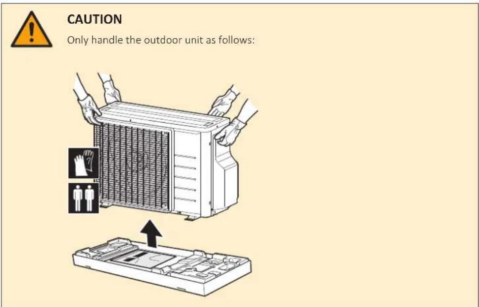
1 Lift the outdoor unit.
text_image
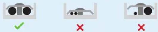
CAUTION Only handle the outdoor unit as follows:2 Remove the accessories at the bottom of the package.
a Outdoor unit installation manual
b General safety precautions
c Fluorinated greenhouse gases label
d Multilingual fluorinated greenhouse gases label
e Drain socket
f Screw bag (for fixing wire retainer)
g Reducer assembly
h Energy label
5 About the unit

INFORMATION
It is NOT possible to connect an indoor unit of 1 room only. Be sure to connect indoor units of at least 2 rooms.

INFORMATION
Depending on the units and/or the installation conditions, it might be necessary to connect electrical wiring before you can charge refrigerant.

WARNING: MILDLY FLAMMABLE MATERIAL
The refrigerant inside this unit is mildly flammable.

WARNING: FLAMMABLE MATERIAL
The refrigerant inside this unit is mildly flammable.

INFORMATION
For the operation limits see the latest technical data of the outdoor unit on the regional Daikin website (publicly accessible).
5.1 Overview: About the unit
This chapter contains information about:
- Identification of the outdoor unit
5.2 Identification

NOTICE
When installing or servicing several units at the same time, make sure NOT to switch the service panels between different models.
5.2.1 Identification label: Outdoor unit
Location

natural_image
Technical line drawing of a mechanical device with internal components and a black arrow indicating direction (no text or symbols)6 Unit installation

WARNING
Installation shall be done by an installer, the choice of materials and installation shall comply with the applicable legislation. In Europe, EN378 is the applicable standard.
In this chapter
6.1 Preparing the installation site 26
6.1.1 Installation site requirements of the outdoor unit 27
6.1.2 Additional installation site requirements of the outdoor unit in cold climates 29
6.2 Opening the unit.... 30
6.2.1 About opening the unit 30
6.2.2 To open the outdoor unit 30
6.3 Mounting the outdoor unit 30
6.3.1 About mounting the outdoor unit 30
6.3.2 Precautions when mounting the outdoor unit.... 31
6.3.3 To provide the installation structure 31
6.3.4 To install the outdoor unit 32
6.3.5 To provide drainage 32
6.3.5 To prevent the outdoor unit from falling over 33
6.1 Preparing the installation site
Do NOT install the unit in places often used as work place. In case of construction works (e.g. grinding works) where a lot of dust is created, the unit MUST be covered.
Choose an installation location with sufficient space for carrying the unit in and out of the site.

CAUTION
- Check if the installation location can support the unit's weight. Poor installation is hazardous. It can also cause vibrations or unusual operating noise.
- Provide sufficient service space.
-
Do NOT install the unit so that it is in contact with a ceiling or a wall, as this may cause vibrations.
-
Choose a location where the operation noise or the hot/cold air discharged from the unit will not disturb anyone.
- Provide sufficient space around the unit for servicing and air circulation.
- Avoid areas where flammable gas or product might leak.
- Install units, power cables and communication wiring at least 3 m away from televisions or radios to prevent interference. Depending on the radio waves, a distance of 3 m may not be sufficient.

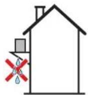
NOTICE
Do NOT place objects below the indoor and/or outdoor unit that may get wet. Otherwise condensation on the unit or refrigerant pipes, air filter dirt or drain blockage may cause dripping, and objects under the unit may get dirty or damaged.

WARNING
The appliance shall be stored in a room without continuously operating ignition sources (example: open flames, an operating gas appliance or an operating electric heater).
6.1.1 Installation site requirements of the outdoor unit

INFORMATION
Also read the following requirements:
- "2 General safety precautions" [▶ 5].
- "7.1.3 Refrigerant piping length and height difference" [▶ 35].
Mind the following spacing guidelines:
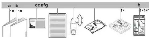
- Wall facing 1 side:
text_image
<1200 >100 a b
- Wall facing 2 sides:
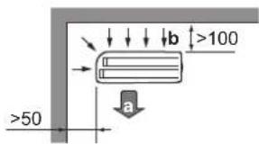
text_image
b ≥100 a ≥50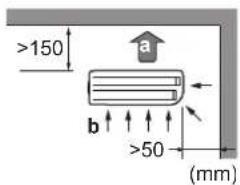
text_image
>150 a b >50 (mm)- Wall facing 3 sides:

text_image
b >150 a >50 >300 (mm)a Air outlet b Air inlet
Allow 300 mm of work space below the ceiling surface and 250 mm for piping and electrical servicing.

text_image
>300 (mm) >250
NOTICE
Do NOT stack the units on each other.
Do NOT hang the unit on a ceiling.
Strong winds ( ≥ 18 km/h) blowing against the outdoor unit's air outlet causes short circuit (suction of discharge air). This may result in:
■ deterioration of the operational capacity;
- frequent frost acceleration in heating operation;
- disruption of operation due to decrease of low pressure or increase of high pressure;
- a broken fan (if a strong wind blows continuously on the fan, it may start rotating very fast, until it breaks).
It is recommended to install a baffle plate when the air outlet is exposed to wind.
It is recommended to install the outdoor unit with the air inlet facing the wall and NOT directly exposed to the wind.

text_image
Diagram illustrating airflow or ventilation system inside a brick wall, labeled with components a, b, and c.a Baffle plate
b Prevailing wind direction
c Air outlet
Do NOT install the unit in the following places:
- Sound sensitive areas (e.g. near a bedroom), so that the operation noise will cause no trouble.
Note: If the sound is measured under actual installation conditions, the measured value might be higher than the sound pressure level mentioned in Sound spectrum in the data book due to environmental noise and sound reflections.

INFORMATION
The sound pressure level is less than 70 dBA.
- In places where a mineral oil mist, spray or vapour may be present in the atmosphere. Plastic parts may deteriorate and fall off or cause water leakage.
It is NOT recommended to install the unit in the following places because it may shorten the life of the unit:
■ Where the voltage fluctuates a lot
- In vehicles or vessels
■ Where acidic or alkaline vapour is present
Seaside installation. Make sure the outdoor unit is NOT directly exposed to sea winds. This is to prevent corrosion caused by high levels of salt in the air, which might shorten the life of the unit.
Install the outdoor unit away from direct sea winds.
Example: Behind the building.

text_image
a b cIf the outdoor unit is exposed to direct sea winds, install a windbreaker.
- Height of windbreaker≥1.5×height of outdoor unit
- Mind the service space requirements when installing the windbreaker.

text_image
a d c d c ba Sea wind
b Building
c Outdoor unit
d Windbreaker
The outdoor unit is designed for outdoor installation only, and for ambient temperatures within the following ranges:
| Cooling mode Heating | mode |
| -10~46°C DB -15~ | 24°C DB |
6.1.2 Additional installation site requirements of the outdoor unit in cold climates
Protect the outdoor unit against direct snowfall and take care that the outdoor unit is NEVER snowed up.

text_image
Diagram of a brick wall structure with labeled components and airflow direction arrowsa Snow cover or shed
b Pedesta
c Prevailing wind direction
d Air outlet
It is recommended to provide at least 150 mm of free space below the unit (300 mm for heavy snowfall areas). Additionally, make sure the unit is positioned at least 100 mm above the maximum expected level of snow. If necessary, construct a pedestal. See "6.3 Mounting the outdoor unit" [▶ 30] for more details.
In heavy snowfall areas it is very important to select an installation site where the snow will NOT affect the unit. If lateral snowfall is possible, make sure that the heat exchanger coil is NOT affected by the snow. If necessary, install a snow cover or shed and a pedestal.
6.2 Opening the unit
6.2.1 About opening the unit
At certain times, you have to open the unit. Example:
- When connecting the refrigerant piping
- When connecting the electrical wiring
- When maintaining or servicing the unit

DANGER: RISK OF ELECTROCUTION
Do NOT leave the unit unattended when the service cover is removed.
6.2.2 To open the outdoor unit

DANGER: RISK OF ELECTROCUTION

DANGER: RISK OF BURNING/SCALDING

text_image
Technical diagram of a server rack with labeled components and 2x magnification indicator6.3 Mounting the outdoor unit
6.3.1 About mounting the outdoor unit
When
The outdoor and indoor unit must be mounted before the refrigerant piping can be connected.
Typical workflow
Mounting the outdoor unit typically consists of the following stages:
1 Providing the installation structure.
2 Installing the outdoor unit.
3 Providing drainage.
4 Protecting the unit against snow and wind by installing a snow cover and baffle plates. See "6.1 Preparing the installation site" [▶ 26].
6.3.2 Precautions when mounting the outdoor unit

INFORMATION
Also read the precautions and requirements in the following chapters:
- "2 General safety precautions" [▶ 5]
- "6.1 Preparing the installation site" [▶ 26]
6.3.3 To provide the installation structure
Check the strength and level of the installation ground so that the unit will not cause any operating vibration or noise.
Use a vibration-proof rubber (field supply) in cases where vibrations may be transmitted to the building.
The unit may be installed directly on a concrete veranda or another solid surface as long as it provides proper drainage.
Fix the unit securely by means of foundation bolts in accordance with the foundation drawing.
Prepare 4 sets of M8 or M10 anchor bolts, nuts and washers (field supply).
text_image
20 mm 311 574 240 240 (a) (mm)a 100 mm above expected level of snow
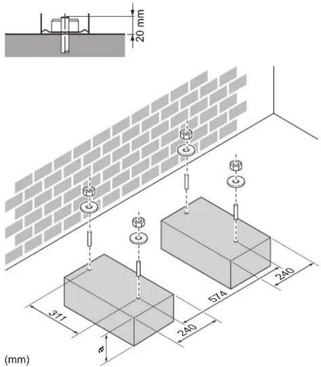
6.3.4 To install the outdoor unit

natural_image
Isometric line drawing of a wall-mounted air conditioner unit mounted on a base, with brick walls and a wall-mounted sensor attached (no text or symbols)6.3.5 To provide drainage
■ Make sure that condensation water can be evacuated properly.
- Install the unit on a base to make sure that there is proper drainage in order to avoid ice accumulation.
- Prepare a water drainage channel around the foundation to drain waste water away from the unit.
- Avoid drain water flowing over the footpath, so that it does NOT become slippery in case of ambient freezing temperatures.
- If you install the unit on a frame, install a waterproof plate within 150 mm of the bottom side of the unit in order to prevent water from getting into the unit and to avoid drain water dripping (see the following figure).

NOTICE
If the unit is installed in a cold climate, take adequate measures so that the evacuated condensate CANNOT freeze.

NOTICE
If the drain holes of the outdoor unit are blocked up by a mounting base or floor surface, place additional foot bases ≤ 30 mm under the outdoor unit's feet.

INFORMATION
For information on the available options, contact your dealer.
1 Use a drain plug for drainage.
2 Use a ∅16 mm hose (field supply).

text_image
Technical diagram showing a mechanical component with labeled parts a, b, c, and d, alongside a schematic of a tool or device.a Drain port
b Bottom frame
c Drain plug
d Hose (field supply)
6.3.6 To prevent the outdoor unit from falling over
In case the unit is installed in places where strong wind can tilt the unit, take following measure:
1 Prepare 2 cables as indicated in the following illustration (field supply).
2 Place the 2 cables over the outdoor unit.
3 Insert a rubber sheet between the cables and the outdoor unit to prevent the cables from scratching the paint (field supply).
4 Attach the ends of the cables.
5 Tighten the cables.

natural_image
Isometric illustration of a heat exchanger or cooling unit with attached sensors and cooling fins (no text or symbols)7 Piping installation
In this chapter
7.1 Preparing refrigerant piping 34
7.1.1 Refrigerant piping requirements 34
7.1.2 Refrigerant piping insulation 35
7.1.3 Refrigerant piping length and height difference 35
7.2 Connecting the refrigerant piping 36
7.2.1 About connecting the refrigerant piping 36
7.2.2 Precautions when connecting the refrigerant piping.... 36
7.2.3 Guidelines when connecting the refrigerant piping.... 38
7.2.4 Pipe bending guidelines 38
7.2.5 To flare the pipe end 38
7.2.6 Connections between outdoor and indoor unit using reducers.... 39
7.2.7 Using the stop valve and service port 40
7.2.8 To connect the refrigerant piping to the outdoor unit 42
7.3 Checking the refrigerant piping.... 42
7.3.1 About checking the refrigerant piping.... 42
7.3.2 Precautions when checking the refrigerant piping 43
7.3.3 To check for leaks.... 43
7.3.4 To perform vacuum drying 44
7.1 Preparing refrigerant piping
7.1.1 Refrigerant piping requirements

INFORMATION
Also read the precautions and requirements in the "2 General safety precautions" [▶ 5].
- Piping material: Phosphoric acid deoxidised seamless copper.
- Piping diameter:
| Class 40 | |
| Liquid piping 2×∅6.4 mm (1/4") | |
| Gas piping 2×∅9.5 mm (3/8") | |
| Class 50 | |
| Liquid piping 2×∅6.4 mm (1/4") | |
| Gas piping 1×∅9.5 mm (3/8") | 1×∅12.7 mm (1/2") |
- Piping temper grade and thickness:
| Outer diameter (∅) | Temper grade Thickness (t) | (a) | |
| 6.4 mm (1/4") Annealed (O) | ≥ 0.8 | mm |  . . |
| 9.5 mm (3/8") | |||
| 12.7 mm (1/2") |
(a) Depending on the applicable legislation and the maximum working pressure of the unit (see "PS High" on the unit name plate), larger piping thickness might be required.
Usage of reducers might be required based on the indoor unit. See "7.2.6 Connections between outdoor and indoor unit using reducers" [▶ 39] for more information.
7.1.2 Refrigerant piping insulation
- Use polyethylene foam as insulation material:
- with a heat transfer rate between 0.041 and 0.052 W/mK (0.035 and 0.045 kcal/mh°C)
- with a heat resistance of at least 120°C
- Insulation thickness
| Pipe outer diameter ( _p ) | Insulation inner diameter ( _i ) | Insulation thickness (t) |
| 6.4 mm (1/4") 8~10 mm ≥10 mm | ||
| 9.5 mm (3/8") 12~15 mm ≥13 mm | ||
| 12.7 mm (1/2") 14~16 mm ≥13 mm |

If the temperature is higher than 30^ C and the humidity is higher than RH 80%, the thickness of the insulation materials should be at least 20 mm to prevent condensation on the surface of the insulation.
7.1.3 Refrigerant piping length and height difference
The shorter the refrigerant piping, the better the performance of the system.
The piping length and height differences must comply with the following requirements.
| Model Minimum required space | |
| Class 40 1.2 m | ^2 |
| Class 50 1.8 m | ^2 |
Shortest allowable length per room is 3 m.
| Refrigerant piping length to each indoor unit ≤20 m | |
| Refrigerant piping total length ≤30 m |
| Height difference outdoor-indoor | Height difference indoor-indoor | |
| Outdoor unit installed higher than indoor unit | ≤15 m ≤7.5 m | |
| Outdoor unit installed lower than at least 1 indoor unit | ≤7.5 m ≤15 m |
7.2 Connecting the refrigerant piping

CAUTION
- No brazing or welding on site for units with R32 refrigerant charge during shipment.
During installation of the refrigeration system, joining of parts with at least one part charged shall be performed taking into account the following requirements:
→ inside occupied spaces non permanent joints are not allowed for R32 refrigerant except for site made joints directly connecting the indoor unit to piping. Site made joints directly connecting piping to indoor units shall be of non permanent type.

CAUTION
Do NOT connect the embedded branch piping and the outdoor unit when only carrying out piping work without connecting the indoor unit in order to add another indoor unit later.

WARNING
- Only use R32 as refrigerant. Other substances may cause explosions and accidents.
■ R32 contains fluorinated greenhouse gases. Its global warming potential (GWP) value is 675. Do NOT vent these gases into the atmosphere. - When charging refrigerant, ALWAYS use protective gloves and safety glasses.
7.2.1 About connecting the refrigerant piping
Before connecting the refrigerant piping
Make sure the outdoor and indoor unit are mounted.
Typical workflow
Connecting the refrigerant piping involves:
- Connecting the refrigerant piping to the indoor unit
- Connecting the refrigerant piping to the outdoor unit
■ Insulating the refrigerant piping - Keeping in mind the guidelines for:
- Pipe bending
- Flaring pipe ends
- Using the stop valves
7.2.2 Precautions when connecting the refrigerant piping

INFORMATION
Also read the precautions and requirements in the following chapters:
■ "2 General safety precautions" [▶ 5]
"7.1 Preparing refrigerant piping" [▶ 34]

DANGER: RISK OF BURNING/SCALDING

CAUTION
- Do NOT use mineral oil on flared part.
- Do NOT reuse piping from previous installations.
- NEVER install a drier to this R32 unit to guarantee its lifetime. The drying material may dissolve and damage the system.

CAUTION
- Use the flare nut fixed to the main unit.
- To prevent gas leakage, apply refrigeration oil only to the inside of the flare. Use refrigeration oil for R32.
Do NOT reuse joints.

NOTICE
Take the following precautions on refrigerant piping into account:
- Avoid anything but the designated refrigerant to get mixed into the refrigerant cycle (e.g. air).
- Only use R32 when adding refrigerant.
- Only use installation tools (e.g. manifold gauge set) that are exclusively used for R32 installations to withstand the pressure and to prevent foreign materials (e.g. mineral oils and moisture) from mixing into the system.
- Install the piping so that the flare is NOT subjected to mechanical stress.
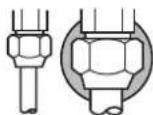
- Protect the piping as described in the following table to prevent dirt, liquid or dust from entering the piping.
- Use caution when passing copper tubes through walls (see figure below).

√
×

√
×
| Unit Installation | period Protection method | |
| Outdoor unit >1 month Pinch | the pipe | |
| <1 month Pinch or tape the pipe | ||
| Indoor unit Regardless of the period | ||

INFORMATION
Do NOT open the refrigerant stop valve before checking the refrigerant piping. When you need to charge additional refrigerant it is recommended to open the refrigerant stop valve after charging.

WARNING
Connect the refrigerant piping securely before running the compressor. If the refrigerant piping is NOT connected and the stop valve is open when the compressor is run, air will be sucked in. This will cause abnormal pressure in the refrigeration cycle, which may result in equipment damage and even injury.

NOTICE
Even if the stop valve is fully closed, the refrigerant may slowly leak out. Do NOT leave the flare nut removed for long period of time.
7.2.3 Guidelines when connecting the refrigerant piping
Take the following guidelines into account when connecting pipes:
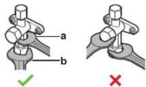
- Coat the flare inner surface with ether oil or ester oil when connecting a flare nut. Tighten 3 or 4 turns by hand, before tightening firmly.

- ALWAYS use 2 wrenches together when loosening a flare nut.
- ALWAYS use a spanner and torque wrench together to tighten the flare nut when connecting the piping. This to prevent nut cracking and leaks.

a Torque wrench
b Spanner
c Piping union
d Flare nut
| Piping size (mm) Tightening torque(N•m) | Flare dimensions(A) (mm) | Flare shape (mm) | |
| ∅6.4 15~17 8.7~9.1 |  | ||
| ∅9.5 33~39 12.8~13.2 | |||
| ∅12.7 50~60 16.2~16.6 | |||
7.2.4 Pipe bending guidelines
Use a pipe bender for bending. All pipe bends should be as gentle as possible (bending radius should be 30\~40 mm or larger).
7.2.5 To flare the pipe end

CAUTION
- Incomplete flaring may cause refrigerant gas leakage.
- Do NOT re-use flares. Use new flares to prevent refrigerant gas leakage.
- Use flare nuts that are included with the unit. Using different flare nuts may cause refrigerant gas leakage.
1 Cut the pipe end with a pipe cutter.
2 Remove burrs with the cut surface facing down so that the chips do NOT enter the pipe.
a Cut exactly at right angles. b Remove burrs.
3 Remove the flare nut from the stop valve and put the flare nut on the pipe.
4 Flare the pipe. Set exactly at the position as shown in the following figure.
| Flare tool for R32(clutch type) | Conventional flare tool | ||
| Clutch type(Ridgid-type) | Wing nut type(Imperial-type) | ||
| A 0~0.5 | mm 1.0~1.5 mm 1.5~2.0 | mm | |
5 Check that the flaring is properly made.
a Flare's inner surface MUST be flawless.
b The pipe end MUST be evenly flared in a perfect circle.
c Make sure the flare nut is fitted.
7.2.6 Connections between outdoor and indoor unit using reducers
Total indoor unit capacity class that can be connected to this outdoor unit:
| Outdoor unit Total indoor unit capacity class | |
| 2MXM40, 2AMXM40, 2AMXF40, 2MXF40 | ≤6.0 kW |
| 2MXM50, 2AMXM50, 2AMXF50, 2MXF50 | ≤8.5 kW |
| Port Class Reducer | ||
| 2MXM40, 2AMXM40 | ||
| A 15, 20, 25, 35 — | ||
| B 15, 20, 25, 35 — | ||
| 2AMXF40 | ||
| A 25, 35 — | ||
| B 25, 35 — | ||
| 2MXF40 | ||
| A 20, 25, 35 — | ||
| B 20, 25, 35 — | ||
| 2MXM50, 2AMXM50 | ||
| A 15, 20, 25, 35, 42 | (a) | — |
| B 15, 20, 25, 35 1+2 | ||
| 42, 50 — | ||
| 2AMXF50 | ||
| A 25, 35 — | ||
| B 25, 35 1+2 | ||
| 2MXF50 | ||
| A 20, 25, 35 — | ||
| B 20, 25, 35 1+2 | ||
(a) Use optional accessory.
| Reducer type Connection | ||
1 ∅12.7 mm → ∅9.5 mm | ||
2 ∅12.7 mm → ∅9.5 mkm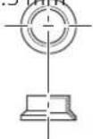 | ||
Connection example:
- Connecting a ∅9.5 mm pipe to a ∅12.7 mm gas pipe connection port
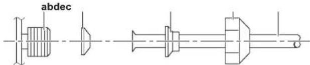
text_image
abdeca Outdoor unit connection port
b Reducer type 1
c Reducer type 2
d Flare nut for ∅12.7 mm
e Inter-unit piping
Coat the threaded connection port of the outdoor unit where the flare nut comes in with refrigeration oil.

NOTICE
Use an appropriate wrench to avoid damaging the connection thread by overtightening the flare nut. Be careful NOT to overtighten the nut, or the smaller pipe may be damaged (about 2/3-1× the normal torque).
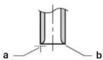
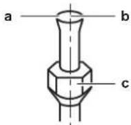
7.2.7 Using the stop valve and service port
To handle the stop valve
Take the following guidelines into account:
- The stop valves are factory closed.
- The following figure shows the stop valve parts required when handling the valve.
a Service port and service port cap
b Valve stem
c Field piping connection
d Stem cap
- Keep both stop valves open during operation.
- Do NOT apply excessive force to the valve stem. Doing so may break the valve body.
- ALWAYS make sure to secure the stop valve with a spanner, then loosen or tighten the flare nut with a torque wrench. Do NOT place the spanner on the stem cap, as this could cause a refrigerant leak.
text_image
a b ✓ ×a Spanner
b Torque wrench
- When it is expected that the operating pressure will be low (e.g. when cooling will be performed while the outside air temperature is low), sufficiently seal the flare nut in the stop valve on the gas line with silicon sealant to prevent freezing.

Silicon sealant, make sure there is no gap.
To open/close the stop valve
1 Remove the stop valve cover.
2 Insert a hexagon wrench (liquid side: 4 mm, gas side: 6 mm) into the valve stem and turn the valve stem:

Counterclockwise to open Clockwise to close
3 When the stop valve CANNOT be turned any further, stop turning.
4 Install the stop valve cover.
Result: The valve is now open/closed.
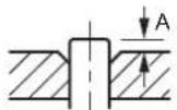
To handle the stem cap
- The stem cap is sealed where indicated with the arrow. Do NOT damage it.
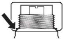
- After handling the stop valve, tighten the stem cap, and check for refrigerant leaks.
| Stem cap Piping ∅ (mm) Tightening torque (N·m) | ||
| Liquid side 6.4 22~28 | ||
| Gas side 9.5 33~39 | ||
| 12.7 49~59 | ||
To handle the service cap
- ALWAYS use a charge hose equipped with a valve depressor pin, since the service port is a Schrader type valve.
- After handling the service port, tighten the service port cap, and check for refrigerant leaks.
| Item Tightening torque (N·m) | |
| Service port cap 11~14 | |
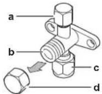
7.2.8 To connect the refrigerant piping to the outdoor unit
- Piping length. Keep field piping as short as possible.
- Piping protection. Protect the field piping against physical damage.
1 Connect the liquid refrigerant connection from the indoor unit to the liquid stop valve of the outdoor unit.
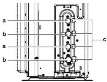
text_image
a b a b ca Liquid stop valve
b Gas stop valve
c Service port
2 Connect the gas refrigerant connection from the indoor unit to the gas stop valve of the outdoor unit.

NOTICE
It is recommended that the refrigerant piping between indoor and outdoor unit is installed in a ducting or the refrigerant piping is wrapped with finishing tape.
7.3 Checking the refrigerant piping
7.3.1 About checking the refrigerant piping
The outdoor unit's internal refrigerant piping has been factory tested for leaks. You only have to check the outdoor unit's external refrigerant piping.
Before checking the refrigerant piping
Make sure the refrigerant piping is connected between the outdoor unit and the indoor unit.
Typical workflow
Checking the refrigerant piping typically consists of the following stages:
1 Checking for leaks in the refrigerant piping.
2 Performing vacuum drying to remove all moisture, air or nitrogen from the refrigerant piping.
If there is a possibility of moisture being present in the refrigerant piping (for example, water may have entered the piping), first carry out the vacuum drying procedure below until all moisture has been removed.
7.3.2 Precautions when checking the refrigerant piping

INFORMATION
Also read the precautions and requirements in the following chapters:
■ "2 General safety precautions" [▶ 5]
- "7.1 Preparing refrigerant piping" [▶ 34]

NOTICE
Use a 2-stage vacuum pump with a non-return valve that can evacuate to a gauge pressure of -100.7 kPa (-1.007 bar)(5 Torr absolute). Make sure the pump oil does not flow oppositely into the system while the pump is not working.

NOTICE
Use this vacuum pump for R32 exclusively. Using the same pump for other refrigerants may damage the pump and the unit.

NOTICE
- Connect the vacuum pump to the service port of the gas stop valve.
- Make sure that the gas stop valve and liquid stop valve are firmly closed before performing the leak test or vacuum drying.
7.3.3 To check for leaks

NOTICE
Do NOT exceed the unit's maximum working pressure (see "PS High" on the unit name plate).

NOTICE
Make sure to use a recommended bubble test solution from your wholesaler. Do not use soap water, which may cause cracking of flare nuts (soap water may contain salt, which absorbs moisture that will freeze when the piping gets cold), and/or lead to corrosion of flared joints (soap water may contain ammonia which causes a corrosive effect between the brass flare nut and the copper flare).
1 Charge the system with nitrogen gas up to a gauge pressure of at least 200 kPa (2 bar). It is recommended to pressurize to 3000 kPa (30 bar) in order to detect small leaks.
2 Check for leaks by applying the bubble test solution to all connections.
3 Discharge all nitrogen gas.
7.3.4 To perform vacuum drying
Connect the vacuum pump and manifold as follows:

text_image
a b c d e f g h k i j ha Low pressure gauge
b Gauge manifold
c High pressure gauge
d Low-pressure valve (Lo)
e High-pressure valve (Hi)
f Charging hoses
g Vacuum pump
h Valve caps
I Service port
j Gas stop valve
k Liquid stop valve

NOTICE
Connect the vacuum pump to both the service ports of the gas stop valves.
1 Vacuum the system until the pressure on the manifold indicates -0.1 MPa (-1 bar).
2 Leave as is for 4-5 minutes and check the pressure:
| If the pressure... Then... | |
| Does not change There is no moisture in the system.This procedure is finished. | |
| Increases There is moisture in the system. Go to the next step. | |
3 Vacuum the system for at least 2 hours to a manifold pressure of -0.1 MPa (-1 bar).
4 After turning the pump OFF, check the pressure for at least 1 hour.
5 If you do NOT reach the target vacuum or CANNOT maintain the vacuum for 1 hour, do the following:
- Check for leaks again.
- Perform vacuum drying again.

NOTICE
Be sure to open the gas stop valve after piping installation and vacuuming. Running the system with the valve closed, the compressor may break down.

INFORMATION
After opening the stop valve, it is possible that the pressure in the refrigerant piping does NOT increase. This might be caused by e.g. the closed state of the expansion valve in the outdoor unit circuit, but does NOT present any problem for correct operation of the unit.
8 Charging refrigerant
In this chapter
8.1 About charging refrigerant 46
8.2 About the refrigerant 47
8.3 Precautions when charging refrigerant 48
8.4 To determine the additional refrigerant amount 48
8.5 To determine the complete recharge amount 48
8.6 To charge additional refrigerant 48
8.7 To fix the fluorinated greenhouse gases label 49
8.1 About charging refrigerant
The outdoor unit is factory charged with refrigerant, but in some cases the following might be necessary:
| What When | |
| Charging additional refrigerant When the | total liquid piping length is more than specified (see later). |
| Completely recharging refrigerant Example: ·When relocating the system. ·After a leak. | |
Charging additional refrigerant
Before charging additional refrigerant, make sure the outdoor unit's external refrigerant piping is checked (leak test, vacuum drying).

INFORMATION
Depending on the units and/or the installation conditions, it might be necessary to connect electrical wiring before you can charge refrigerant.
Typical workflow – Charging additional refrigerant typically consists of the following stages:
1 Determining if and how much you have to charge additionally.
2 If necessary, charging additional refrigerant.
3 Filling in the fluorinated greenhouse gases label, and fixing it to the inside of the outdoor unit.
Completely recharging refrigerant
Before completely recharging refrigerant, make sure the following is done:
1 All refrigerant is recovered from the system.
2 The outdoor unit's external refrigerant piping is checked (leak test, vacuum drying).
3 Vacuum drying on the outdoor unit's internal refrigerant piping is performed.

NOTICE
Before completely recharging, perform vacuum drying on the outdoor unit's internal refrigerant piping as well.
Typical workflow – Completely recharging refrigerant typically consists of the following stages:
1 Determining how much refrigerant to charge.
2 Charging refrigerant.
3 Filling in the fluorinated greenhouse gases label, and fixing it to the inside of the outdoor unit.
8.2 About the refrigerant
This product contains fluorinated greenhouse gases. Do NOT vent gases into the atmosphere.
Refrigerant type: R32
Global warming potential (GWP) value: 675

NOTICE
Applicable legislation on fluorinated greenhouse gases requires that the refrigerant charge of the unit is indicated both in weight and CO_2 equivalent.
Formula to calculate the quantity in CO_2 equivalent tonnes: GWP value of the refrigerant × total refrigerant charge [in kg] / 1000
Please contact your installer for more information.

WARNING: FLAMMABLE MATERIAL
The refrigerant inside this unit is mildly flammable.

WARNING: MILDLY FLAMMABLE MATERIAL
The refrigerant inside this unit is mildly flammable.

WARNING
The appliance shall be stored in a room without continuously operating ignition sources (example: open flames, an operating gas appliance or an operating electric heater).

WARNING
- Do NOT pierce or burn refrigerant cycle parts.
- Do NOT use cleaning materials or means to accelerate the defrosting process other than those recommended by the manufacturer.
- Be aware that the refrigerant inside the system is odourless.

WARNING
The refrigerant inside the unit is mildly flammable, but normally does NOT leak. If the refrigerant leaks in the room and comes in contact with fire from a burner, a heater, or a cooker, this may result in fire, or the formation of a harmful gas.
Turn off any combustible heating devices, ventilate the room, and contact the dealer where you purchased the unit.
Do NOT use the unit until a service person confirms that the part from which the refrigerant leaked has been repaired.

WARNING
NEVER directly touch any accidental leaking refrigerant. This could result in severe wounds caused by frostbite.
8.3 Precautions when charging refrigerant

INFORMATION
Also read the precautions and requirements in the following chapters:
■ "2 General safety precautions" [▶ 5]
- "7.1 Preparing refrigerant piping" [▶ 34]
8.4 To determine the additional refrigerant amount
| If the total liquid piping length is... | Then... |
| ≤20 m Do NOT add additional refrigerant. | |
| >20 m R=(total length (m) of liquid piping-20 m)×0.020R=Additional charge (kg) (rounded in units of 0.1 kg) | |

INFORMATION
Piping length is the one-way length of liquid piping.
8.5 To determine the complete recharge amount

INFORMATION
If a complete recharge is necessary, the total refrigerant charge is: the factory refrigerant charge (see unit name plate) + the determined additional amount.
8.6 To charge additional refrigerant

WARNING
- Only use R32 as refrigerant. Other substances may cause explosions and accidents.
- R32 contains fluorinated greenhouse gases. Its global warming potential (GWP) value is 675. Do NOT vent these gases into the atmosphere.
- When charging refrigerant, ALWAYS use protective gloves and safety glasses.

CAUTION
To avoid compressor breakdown, do NOT charge more than the specified amount of refrigerant.
Prerequisite: Before charging refrigerant, make sure the refrigerant piping is connected and checked (leak test and vacuum drying).
1 Connect the refrigerant cylinder to the service port.
2 Charge the additional refrigerant amount.
3 Open the gas stop valve.
8.7 To fix the fluorinated greenhouse gases label
1 Fill in the label as follows:
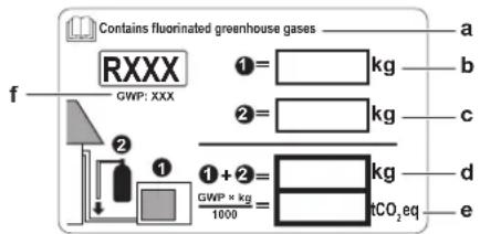
text_image
Contains fluorinated greenhouse gases RXXX GWP: XXX ①= kg ②= kg ① + ② = kg GWP × kg 1000 CO₂eq a b c d ea If a multilingual fluorinated greenhouse gases label is delivered with the unit (see accessories), peel off the applicable language and stick it on top of a.
b Factory refrigerant charge: see unit name plate
c Additional refrigerant amount charged
d Total refrigerant charge
e Quantity of fluorinated greenhouse gases of the total refrigerant charge expressed as tonnes CO₂ equivalent.
f GWP = Global warming potential

NOTICE
Applicable legislation on fluorinated greenhouse gases requires that the refrigerant charge of the unit is indicated both in weight and CO_2 equivalent.
Formula to calculate the quantity in CO_2 equivalent tonnes: GWP value of the refrigerant × total refrigerant charge [in kg] / 1000
Use the GWP value mentioned on the refrigerant charge label.
2 Fix the label on the inside of the outdoor unit near the gas and liquid stop valves.
9 Electrical installation
In this chapter
9.1 About connecting the electrical wiring 50
9.1.1 Precautions when connecting the electrical wiring 50
9.1.2 Guidelines when connecting the electrical wiring 52
9.1.3 Specifications of standard wiring components 53
9.2 To connect the electrical wiring to the outdoor unit 53
9.1 About connecting the electrical wiring
Before connecting the electrical wiring
Make sure:
- The refrigerant piping is connected and checked
- The water piping is connected
Typical workflow
Connecting the electrical wiring typically consists of the following stages:
1 Making sure the power supply system complies with the electrical specifications of the units.
2 Connecting the electrical wiring to the outdoor unit.
3 Connecting the electrical wiring to the indoor unit.
4 Connecting the main power supply.
9.1.1 Precautions when connecting the electrical wiring

WARNING
Appliance shall be installed in accordance with national wiring regulations.

DANGER: RISK OF ELECTROCUTION

INFORMATION
Also read the precautions and requirements in the "2 General safety precautions" [▶ 5].

INFORMATION
Also read "9.1.3 Specifications of standard wiring components" [▶ 53].

WARNING
- All wiring MUST be performed by an authorised electrician and MUST comply with the applicable legislation.
■ Make electrical connections to the fixed wiring. - All components procured on-site and all electrical construction MUST comply with the applicable legislation.

WARNING
- If the power supply has a missing or wrong N-phase, equipment might break down.
- Establish proper earthing. Do NOT earth the unit to a utility pipe, surge absorber, or telephone earth. Incomplete earthing may cause electrical shock.
- Install the required fuses or circuit breakers.
- Secure the electrical wiring with cable ties so that the cables do NOT come in contact with sharp edges or piping, particularly on the high-pressure side.
- Do NOT use taped wires, stranded conductor wires, extension cords, or connections from a star system. They can cause overheating, electrical shock or fire.
- Do NOT install a phase advancing capacitor, because this unit is equipped with an inverter. A phase advancing capacitor will reduce performance and may cause accidents.

WARNING
ALWAYS use multicore cable for power supply cables.

WARNING
Use an all-pole disconnection type breaker with at least 3 mm between the contact point gaps that provide full disconnection under overvoltage category III.

WARNING
If the supply cord is damaged, it MUST be replaced by the manufacturer, its service agent or similarly qualified persons in order to avoid a hazard.

WARNING
Do NOT connect the power supply to the indoor unit. This could result in electrical shock or fire.

WARNING
- Do NOT use locally purchased electrical parts inside the product.
- Do NOT branch the power supply for the drain pump, etc. from the terminal block. This could result in electrical shock or fire.

WARNING
Keep the interconnection wiring away from copper pipes without thermal insulation as such pipes will be very hot.

DANGER: RISK OF ELECTROCUTION
All electrical parts (including thermistors) are powered by the power supply. Do not touch them with bare hands.

DANGER: RISK OF ELECTROCUTION
Disconnect the power supply for more than 10 minutes, and measure the voltage at the terminals of main circuit capacitors or electrical components before servicing. The voltage MUST be less than 50 V DC before you can touch electrical components. For the location of the terminals, see the wiring diagram.

text_image
I a b c k d efghija DB1 diode bridge
b S90 thermistor lead wire
c LED A
d S40 thermal overload relay lead wire
e S20 (white) room A electronic expansion valve coil
f S21 (red) room B electronic expansion valve coil
g S80 (white) 4-way valve lead wire connector
h S70 fan motor lead wire
i S99 heating lock
j S91 (red) liquid thermistor lead wire
k S92 (white)gas thermistor lead wire
I Multimeter (DC voltage range)
9.1.2 Guidelines when connecting the electrical wiring
Keep the following in mind:
- If stranded conductor wires are used, install a round crimp-style terminal on the end of the wire. Place the round crimp-style terminal on the wire up to the covered part and fasten the terminal with the appropriate tool.

a Stranded conductor wire
b Round crimp-style terminal
- Use the following methods for installing wires:
| Wire type Installation method | |
| Single-core wire | 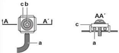 |
| a Curled single-core wireb Screwc Flat washer | |
| Wire type Installation method | ||
| Stranded conductor wire with round crimp-style terminal | cbbac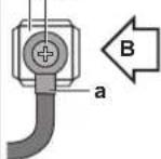 | 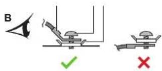 |
| a Terminalb Screwc Flat washerO AllowedX NOT allowed | ||
Tightening torques
| Item Tightening torque (N•m) | |
| M4 (X1M) 1.2 | |
| M4 (earth) | |
- The earth wire between the wire retainer and the terminal must be longer than the other wires.
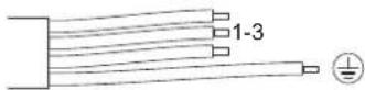
9.1.3 Specifications of standard wiring components
| Component | ||
| Power supply cable Voltage | 220~240 V | |
| Phase 1~ | ||
| Frequency 50 Hz | ||
| Wire type 3-core cable | 2.5 mm ^2 H05RN-F (60245 IEC 57)H07RN-F (60245 IEC 66) | |
| 3-core cable 4.0 mm ^2 H07RN-F (60245 IEC 66) | ||
| Interconnection cable (indoor↔outdoor) 4-core cable 1.5 mm ^2 or 2.5 mm ^2 and applicable for 220~240 VH05RN-F (60245 IEC 57) | ||
| Recommended circuit breaker | 16 A | |
| Residual current device | MUST comply with applicable legislation | |
9.2 To connect the electrical wiring to the outdoor unit
1 Remove the switch box cover (2 screws).

natural_image
Technical line drawing of a server rack unit with internal components and a monitor, showing no text or symbols.2 Strip insulation (20 mm) from the wires.
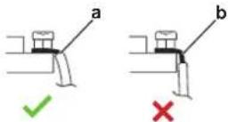
a Strip wire end to this point
b An excessive strip length may cause electrical shock or leakage
3 Connect the wires between the indoor and outdoor units so that the terminal numbers match. Make sure to match the symbols for piping and wiring.
4 Make sure to connect correct wiring to correct room (A to A, B to B).

flowchart
graph TD
    A["Home"] --> B["e-A"]
    B --> C["a-Aa-B"]
    C --> D["f"]
    C --> E["b"]
    C --> F["c"]
    C --> G["d"]
    C --> H["e-B"]
    style A fill:#f9f,stroke:#333
    style B fill:#ccf,stroke:#333
    style C fill:#cfc,stroke:#333
    style D fill:#fcc,stroke:#333
    style E fill:#cff,stroke:#333
    style F fill:#ffc,stroke:#333
    style G fill:#cfc,stroke:#333
    style H fill:#fcc,stroke:#333
a Terminal for room (A, B)
b Circuit breaker
c Earth leakage circuit breaker
d Power supply wire
e Interconnection wire for room (A, B)
f Wire retainer
5 Tighten the terminal screws securely using a Phillips screwdriver.
6 Check that the wires do not disconnect by pulling them lightly.
7 Firmly secure the wire retainer to avoid external stress on wire terminations.
8 Pass the wiring through the cutout on the bottom of the protection plate.
9 Make sure the electrical wiring does not contact with the gas piping.
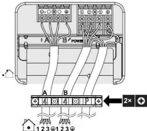
text_image
1 2 3 4 5 6 7 8 9 10 11 12 13 14 15 16 17 18 19 20 21 22 23 24 25 26 27 28 29 30 A B B POWER A B 2x + 1 2 3 4 5 6 7 8 9 10 11 12 13 14 15 16 17 18 19 20 ← 1 2 3 4 5 6 7 8 9 10 11 12 13 14 15 16 17 18 1910 Reattach the switch box cover and the service cover.
10 Finishing the outdoor unit installation
10.1 To finish the outdoor unit installation

DANGER: RISK OF ELECTROCUTION
■ Make sure that the system is earthed properly.
- Turn off the power supply before servicing.
- Install the switch box cover before turning on the power supply.

NOTICE
It is recommended that the refrigerant piping between indoor and outdoor unit is installed in a ducting or the refrigerant piping is wrapped with finishing tape.
1 Insulate and fix the refrigerant piping and cables as follows:
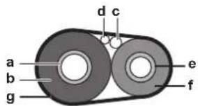
text_image
a b g d c e fa Gas pipe
b Gas pipe insulation
c Interconnection cable
d Field wiring (if applicable)
e Liquid pipe
f Liquid pipe insulation
g Finishing tape
2 Install the service cover.
10.2 To close the outdoor unit
1 Close the switch box cover.
2 Close the service cover.

NOTICE
When closing the outdoor unit cover, make sure that the tightening torque does NOT exceed 4.1 N•m.
11 Configuration
In this chapter
11.1 About ECONO mode prohibition setting.... 56
11.1.1 To turn on ECONO mode prohibition setting 56
11.2 About night quiet mode 57
11.2.1 To turn on the night quiet mode 57
11.3 About heat mode lock 57
11.3.1 To turn on heat mode lock.... 57
11.4 About standby electricity saving function.... 58
11.4.1 To turn on standby electricity saving function 58
11.1 About ECONO mode prohibition setting
This setting disables the input control signal from the user interface. Use this setting when you wish to block reception of input controls (cooling/heating) from indoor unit user interfaces.
11.1.1 To turn on ECONO mode prohibition setting
Prerequisite: The main power supply MUST be turned off.
1 Remove the top plate of the outdoor unit (2 screws on sides)
2 Remove the electric box cover by sliding it. Be careful not to bend the electric box hook.
3 Cut the jumper (J23).
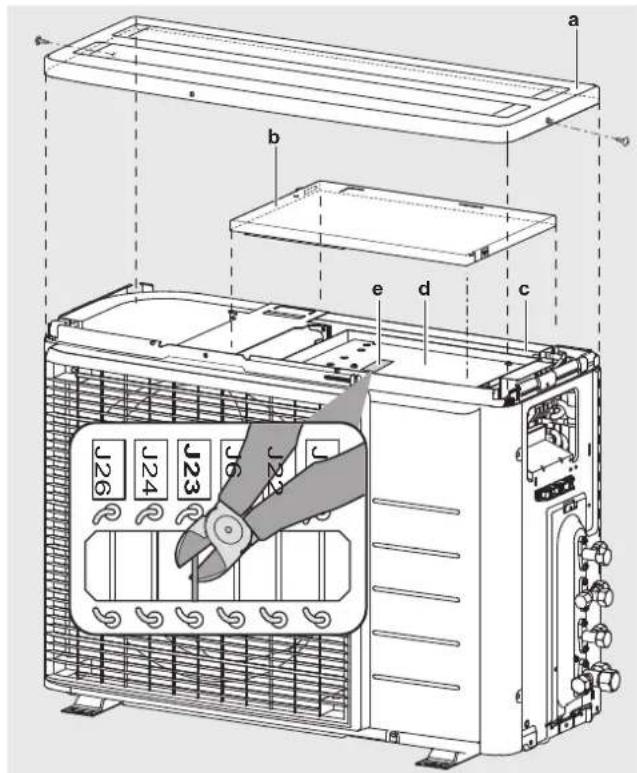
text_image
a b c d e J26 J24 J23 J6 J23a Top plate
b Electric box cover
c Electric box
d PCB
e PCB jumpers
4 Reinstall the electric box cover and the top plate in reverse order and turn on the main power supply.
11.2 About night quiet mode
The night quiet mode function makes the outdoor unit run more quietly at nighttime. This will reduce the cooling capacity of the unit. Explain Night quiet mode to the customer and confirm if customer wants to use this mode.
11.2.1 To turn on the night quiet mode
Prerequisite: The main power supply MUST be turned off.
1 Remove the top plate and the electric box cover of the outdoor unit (see "11.1.1 To turn on ECONO mode prohibition setting" [▶ 56])
2 Cut the jumper J6.

3 Reinstall the top plate and the electric box cover.

CAUTION
When reinstalling the electric box cover, be careful not to pinch the fan motor lead wire.
11.3 About heat mode lock
Heat mode lock limits the unit to heat operation.
11.3.1 To turn on heat mode lock
1 Remove the top plate (2 screws) and the front plate (8 screws).
2 To set heat mode lock remove the S99 connector.
3 To reset the heat pump mode (cooling/heating), plug the connector back.
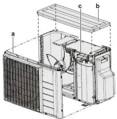
text_image
Technical diagram of a mechanical device with labeled components a, b, and ca Front plate
b Top plate
c S99 connector
| Mode S99 connector | |
| Heat pump (cooling, heating) Connected | |
| Heating only Disconnected |
4 Reinstall the top plate and the front plate.

INFORMATION
Forced operation is also available in heating mode.
11.4 About standby electricity saving function
The standby electricity saving function:
- turns OFF the power supply to the outdoor unit and,
- turns ON the standby electricity saving mode on the indoor unit.
The standby electricity saving function works with following units:
FTXM, FTXP, FTXJ, FVXM, ATXF
If another indoor unit is used, the connector for standby electric saving must be plugged in.
The standby electricity saving function is turned off before shipping.
11.4.1 To turn on standby electricity saving function
Prerequisite: The main power supply MUST be turned off.
1 Remove the service cover.
2 Disconnect the selective standby electricity saving connector.
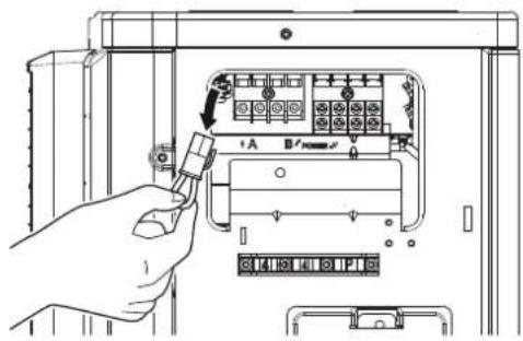
text_image
Diagram showing a hand inserting a component into an electrical meter panel with labeled pins and labels3 Turn on the main power supply.
12 Commissioning
In this chapter
12.1 Overview: Commissioning 59
12.2 Precautions when commissioning.... 59
12.3 Checklist before commissioning.... 59
12.4 Checklist during commissioning 60
12.5 Trial operation and testing.... 60
12.5.1 To perform a test run.... 60
12.6 Starting up the outdoor unit 61
12.1 Overview: Commissioning
This chapter describes what you have to do and know to commission the system after it is installed.
Typical workflow
Commissioning typically consists of the following stages:
1 Checking the "Checklist before commissioning".
2 Performing a test run for the system.
12.2 Precautions when commissioning

INFORMATION
During the first running period of the unit, the required power may be higher than stated on the nameplate of the unit. This phenomenon is caused by the compressor, that needs a continuous run time of 50 hours before reaching smooth operation and stable power consumption.

NOTICE
ALWAYS operate the unit with thermistors and/or pressure sensors/switches. If NOT, burning of the compressor might be the result.

NOTICE
ALWAYS complete the refrigerant piping of the unit before operating. If NOT, the compressor will break.
12.3 Checklist before commissioning
After the installation of the unit, first check the items listed below. Once all checks are fulfilled, the unit must be closed. Power-up the unit after it is closed.
| ☐ | The indoor unit is properly mounted. |
| ☐ | The outdoor unit is properly mounted. |
| ☐ | The system is properly earthed and the earth terminals are tightened. |
| ☐ | The power supply voltage matches the voltage on the identification label of the unit. |
| There are NO loose connections or damaged electrical components in the switch box. | |
| There are NO damaged components or squeezed pipes on the inside of the indoor and outdoor units. | |
| There are NO refrigerant leaks. | |
| The refrigerant pipes (gas and liquid) are thermally insulated. | |
| The correct pipe size is installed and the pipes are properly insulated. | |
| The stop valves (gas and liquid) on the outdoor unit are fully open. | |
| DrainageMake sure drainage flows smoothly.Possible consequence: Condensate water might drip. | |
| The indoor unit receives the signals of the user interface. | |
| The specified wires are used for the interconnection cable. | |
| The fuses, circuit breakers, or locally installed protection devices are installed according to this document, and have NOT been bypassed. | |
| Check if marks (room A~E) on the wiring and piping match for each indoor unit. | |
| Check if the priority room setting is set for 2 or more rooms. Keep in mind that the DHW generator for Multi or the Hybrid for Multi shall not be selected as the priority room. |
12.4 Checklist during commissioning
| ☐ | To perform a wiring check. |
| ☐ | To perform an air purge. |
| ☐ | To perform a test run. |
12.5 Trial operation and testing
| ☐ | Before starting the test run, measure the voltage at the primary side of the safety breaker. |
| ☐ | The piping and wiring work match. |
| ☐ | The stop valves (gas and liquid) on the outdoor unit are fully open. |
Initialization of the Multi system can take several minutes depending on the number of indoor units and options used.
12.5.1 To perform a test run
Prerequisite: Power supply MUST be in the specified range.
Prerequisite: Test run operation may be done in cooling or heating mode.
Prerequisite: Test run should be done in accordance with the operation manual of the indoor unit to make sure that all functions and parts are working properly.
1 In cooling mode, select the lowest programmable temperature. In heating mode, select the highest programmable temperature.
2 Measure the temperature at the indoor unit inlet and outlet after running the unit for about 20 minutes. The difference should be more than 8^ C (cooling) or 15^ C (heating).
3 First check operation of each unit individually, then check simultaneous operation of all indoor units. Check both heating and cooling operation.
4 When test run is finished, set the temperature to a normal level. In cooling mode: 26\~28°C, in heating mode: 20\~24°C.

INFORMATION
■ Test run can be disabled if necessary.
■ After the unit is turned OFF, it cannot be started again for 3 minutes.
- During cooling operation, frost may form on the gas stop valve or other parts. This is normal.

INFORMATION
Even if the unit is turned OFF, it consumes electricity.
- When the power turns back on after a power break, the previously selected mode will be resumed.
12.6 Starting up the outdoor unit
See the indoor unit installation manual for configuration and commissioning of the system.
13 Hand-over to the user
Once the test run is finished and the unit operates properly, please make sure the following is clear for the user:
- Make sure that the user has the printed documentation and ask him/her to keep it for future reference. Inform the user that he can find the complete documentation at the URL mentioned earlier in this manual.
- Explain the user how to properly operate the system and what to do in case of problems.
- Show the user what to do for the maintenance of the unit.
14 Maintenance and service

NOTICE
Maintenance MUST be done by an authorized installer or service agent.
We recommend performing maintenance at least once a year. However, applicable legislation might require shorter maintenance intervals.

NOTICE
Applicable legislation on fluorinated greenhouse gases requires that the refrigerant charge of the unit is indicated both in weight and CO_2 equivalent.
Formula to calculate the quantity in CO_2 equivalent tonnes: GWP value of the refrigerant × total refrigerant charge [in kg] / 1000
14.1 Overview: Maintenance and service
This chapter contains information about:
- Maintenance safety precautions
- The yearly maintenance of the outdoor unit
14.2 Maintenance safety precautions

DANGER: RISK OF ELECTROCUTION

DANGER: RISK OF BURNING/SCALDING

NOTICE: Risk of electrostatic discharge
Before performing any maintenance or service work, touch a metal part of the unit in order to eliminate static electricity and to protect the PCB.

WARNING
Before carrying out any maintenance or repair activity, ALWAYS switch off the circuit breaker on the supply panel, remove the fuses or open the protection devices of the unit.
- Do NOT touch live parts for 10 minutes after the power supply is turned off because of high voltage risk.
- Please note that some sections of the electric component box are hot.
■ Make sure you do NOT touch a conductive section.
- Do NOT rinse the unit. This may cause electric shocks or fire.
14.3 Checklist for yearly maintenance of the outdoor unit
Check the following at least once a year:
- Heat exchanger
The heat exchanger of the outdoor unit can get blocked up due to dust, dirt, leaves, etc. It is recommended to clean the heat exchanger yearly. A blocked heat exchanger can lead to too low pressure or too high pressure leading to worse performance.
14.4 About the compressor
When servicing the compressor keep in mind following precautions:

DANGER: RISK OF ELECTROCUTION
- Use this compressor on a grounded system only.
■ Turn the power off before servicing the compressor. - Reattach the switch box cover and service lid after servicing.

CAUTION
Always wear safety goggles and protective gloves.

DANGER: RISK OF EXPLOSION
- Use a pipe cutter to remove the compressor.
- Do NOT use the brazing torch.
■ Use approved refrigerants and lubricants only.

DANGER: RISK OF BURNING/SCALDING
Do NOT touch the compressor with bare hands.
15 Troubleshooting
15.1 Overview: Troubleshooting
This chapter describes what you have to do in case of problems.
It contains information about solving problems based on symptoms.
Before troubleshooting
Carry out a thorough visual inspection of the unit and look for obvious defects such as loose connections or defective wiring.
15.2 Precautions when troubleshooting

WARNING
- When carrying out an inspection on the switch box of the unit, ALWAYS make sure that the unit is disconnected from the mains. Turn off the respective circuit breaker.
- When a safety device was activated, stop the unit and find out why the safety device was activated before resetting it. NEVER shunt safety devices or change their values to a value other than the factory default setting. If you are unable to find the cause of the problem, call your dealer.

DANGER: RISK OF ELECTROCUTION

WARNING
Prevent hazards due to inadvertent resetting of the thermal cut-out: power to this appliance MUST NOT be supplied through an external switching device, such as a timer, or connected to a circuit that is regularly turned ON and OFF by the utility.

DANGER: RISK OF BURNING/SCALDING
15.3 Solving problems based on symptoms
15.3.1 Symptom: Indoor units fall, vibrate or make noise
| Possible causes Corrective action | |
| The indoor units are not installed securely | Install the indoor units securely. |
15.3.2 Symptom: The unit is NOT heating or cooling as expected
| Possible causes Corrective action | |
| Wrong connection of the electrical wires | Connect the electrical wires correctly. |
| Gas leakage Check for gas leakage. | |
| Marks on the wiring and piping do NOT match | Marks on the wiring and piping (room A, room B, room C, room D, room E) for each indoor unit MUST match. |
15.3.3 Symptom: Water leakage
| Possible causes Corrective action | |
| Incomplete thermal insulation (gas and liquid piping, indoor portions of the drain hose extension) | Make sure the thermal insulation of the piping and the drain hose is complete. |
| Improperly connected drainage Secure the drainage. | |
15.3.4 Symptom: Electrical leakage
| Possible causes Corrective action | |
| The unit is NOT earthed correctly Check and correct the connection of the earth wiring. |
15.3.5 Symptom: Unit does NOT function or burn damage
| Possible causes Corrective action | |
| The wiring was NOT performed in accordance with the specifications | Correct the wiring. |
15.4 Solving problems based on LED behaviour
15.4.1 Fault diagnosis using LED on outdoor unit PCB
| LED is... Diagnosis | ||
| flashing Normal.· Check the indoor unit. | ||
| ON · Turn the | power OFF and back ON, and check the LED within approximately 3 minutes.If the LED is ON again, the outdoor unit PCB is faulty. | |
| OFF 1 Supply voltage (for power saving).2 Power supply fault.Turn the power OFF and back ON, and check the LED within approximately 3 minutes.If the LED is OFF again, the outdoor unit PCB is faulty. | ||

DANGER: RISK OF ELECTROCUTION
- When the unit is not operating, the LEDs on the PCB are turned off in order to save power.
Even when the LEDs are off, the terminal block and the PCB may be powered.
16 Disposal

NOTICE
Do NOT try to dismantle the system yourself: dismantling of the system, treatment of the refrigerant, oil and other parts MUST comply with applicable legislation. Units MUST be treated at a specialised treatment facility for reuse, recycling and recovery.
16.1 Overview: Disposal
Typical workflow
Disposing of the system typically consists of the following stages:
1 Pumping down the system.
2 Bringing the system to a specialized treatment facility.

INFORMATION
For more details, see the service manual.
16.2 To pump down
Example: To protect the environment, pump down when relocating the unit or when disposing of the unit.

DANGER: RISK OF EXPLOSION
Pump down – Refrigerant leakage. If you want to pump down the system, and there is a leak in the refrigerant circuit:
- Do NOT use the unit's automatic pump down function, with which you can collect all refrigerant from the system into the outdoor unit. Possible consequence: Self-combustion and explosion of the compressor because of air going into the operating compressor.
- Use a separate recovery system so that the unit's compressor does NOT have to operate.

NOTICE
During pump down operation, stop the compressor before removing the refrigerant piping. If the compressor is still running and the stop valve is open during pump down, air will be sucked into the system. Compressor breakdown or damage to the system can result due to abnormal pressure in the refrigerant cycle.
Pump down operation will extract all refrigerant from the system into the outdoor unit.
1 Remove the valve cap from the liquid stop valve and the gas stop valve.
2 Carry out forced cooling. See "16.3 To start and stop forced cooling" [▶ 69].
3 After 5 to 10 minutes (after only 1 or 2 minutes in case of very low ambient temperatures (<-10°C)), close the liquid stop valve with a hexagonal wrench.
4 Check on the manifold if the vacuum is reached.
5 After 2-3 minutes, close the gas stop valve and stop forced cooling.

text_image
a b c d e da Gas stop valve
b Closing direction
c Hexagonal wrench
d Valve cap
e Liquid stop valve
16.3 To start and stop forced cooling
There are 2 methods to perform forced cooling.
- Method 1. Using the indoor unit ON/OFF switch (if present on the indoor unit).
• Method 2. Using the indoor unit user interface.
16.3.1 To start and stop forced cooling using the indoor unit ON/OFF switch
1 Press the ON/OFF switch for at least 5 seconds.
Result: Operation will start.

INFORMATION
Forced cooling stops automatically after 15 minutes.
2 To stop operation sooner, press the ON/OFF switch.
16.3.2 To start and stop forced cooling using the indoor unit user interface
1 Set the operation mode to cooling. Refer to "To perform a test run" in the installation manual of the indoor unit.
17 Technical data
- A subset of the latest technical data is available on the regional Daikin website (publicly accessible).
- The full set of latest technical data is available on the Daikin Business Portal (authentication required).
17.1 Wiring diagram
17.1.1 Unified wiring diagram legend
For applied parts and numbering, refer to the wiring diagram on the unit. Part numbering is by Arabic numbers in ascending order for each part and is represented in the overview below by "*" in the part code.
| Symbol Meaning | Symbol Meaning | ||
| Circuit breaker Protective earth | |||
| Connection Protective earth (screw) | |||
| Connector | A | Rectifier | |
| Earth Relay connector | |||
| Field wiring Short-circuit connector | |||
| Fuse Terminal | |||
| Indoor unit Terminal strip | |||
| Outdoor unit Wire clamp | |||
| Residual current device | |||
| Symbol Colour | Symbol | Colour | |
| BLK | Black | ORG | Orange |
| BLU | Blue | PNK | Pink |
| BRN | Brown | PRP, PPL | Purple |
| GRN | Green | RED | Red |
| GRY | Grey | WHT | White |
| YLW | Yellow | ||
| Symbol | Meaning |
| A*P | Printed circuit board |
| BS* | Pushbutton ON/OFF, operation switch |
| BZ, H*O | Buzzer |
| C* | Capacitor |
| Symbol Meaning | |
| AC*, CN*, E*, HA*, HE*, HL*, HN*, HR*, MR*_A, MR*_B, S*, U, V, W, X*A, K*R_*, NE | Connection, connector |
| D*, V*D Diode | |
| DB* Diode bridge | |
| DS* DIP switch | |
| E*H Heater | |
| FU*, F*U, (for characteristics, refer to PCB inside your unit) | Fuse |
| FG* Connector (frame ground) | |
| H* Harness | |
| H*P, LED*, V*L Pilot lamp, light emitting diode | diode |
| HAP Light emitting diode (service monitor green) | |
| HIGH VOLTAGE High voltage | |
| IES Intelligent eye sensor | |
| IPM* Intelligent power module | |
| K*R, KCR, KFR, KHuR, K*M Magnetic relay | |
| L Live | |
| L* Coil | |
| L*R Reactor | |
| M* Stepper motor | |
| M*C | Compressor motor |
| M*F | Fan motor |
| M*P | Drain pump motor |
| M*S | Swing motor |
| MR*, MRCW*, MRM*, MRN* | Magnetic relay |
| N | Neutral |
| n=*, N=* | Number of passes through ferrite core |
| PAM | Pulse-amplitude modulation |
| PCB* Printed circuit board | |
| PM* | Power module |
| PS | Switching power supply |
| PTC* | PTC thermistor |
| Q* Insulated gate bipolar transistor (IGBT) | |
| Q*C Circuit breaker | |
| Q*DI, KLM | Earth leak circuit breaker |
| Q*L | Overload protector |
| Q*M Thermo switch | |
| Q*R Residual current device | |
| R* Resistor | |
| R*T Thermistor | |
| RC Receiver | |
| S*C Limit switch | |
| S*L Float switch | |
| S*NG Refrigerant leak detector | |
| S*NPH Pressure sensor (high) | |
| S*NPL Pressure sensor (low) | |
| S*PH, HPS* Pressure switch (high) | |
| S*PL Pressure switch (low) | |
| S*T Thermostat | |
| S*RH Humidity sensor | |
| S*W, SW* Operation switch | |
| SA*, F1S | Surge arrester |
| SR*, WLU | Signal receiver |
| SS* | Selector switch |
| SHEET METAL | Terminal strip fixed plate |
| T*R Transformer | |
| TC, TRC | Transmitter |
| V*, R*V | Varistor |
| V*R | Diode bridge, Insulated-gate bipolar transistor (IGBT) power module |
| WRC | Wireless remote controller |
| X* | Terminal |
| X*M | Terminal strip (block) |
| Y*E Electronic expansion valve coil | |
| Y*R, Y*S | Reversing solenoid valve coil |
| Z*C Ferrite core | |
| ZF, Z*F | Noise filter |
17.2 Piping diagram: Outdoor unit
Component PED category classification:
- High pressure switches: category IV
- Compressor: category II
- Other components: refer to PED article 4, paragraph 3
2MXM50, 2AMXM50, 2AMXF50, 2MXF50
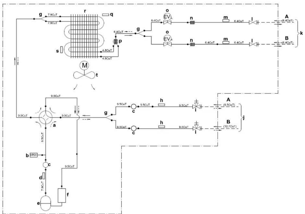
flowchart
graph TD
    subgraph Left_Circuit
        g --> r
        r --> q
        s --> p
        p --> g
        g --> o
        o --> n
        n --> m
        m --> l
        l --> A
        p --> o
        o --> n
        n --> m
        m --> l
        l --> B
    end
    subgraph Right_Circuit
        g --> o
        o --> n
        n --> m
        m --> l
        l --> B
    end
    R["Left Circuit"] --> s
    R --> q
    R --> M
    R --> t
    R --> a
    R --> b
    R --> c
    R --> d
    R --> e
    R --> f
    R --> g
    R --> h
    R --> i
    R --> j
    R --> k
    R --> L
    R --> M
    R --> N
    R --> O
    R --> P
    R --> Q
    R --> R1["PS1"]
    R --> R2["c"]
    R --> R3["7.9CuT"]
    R --> R4["f"]
    R --> S["9.5CuT"]
    R --> T["9.5CuT"]
    R --> U["9.5CuT"]
    R --> V["9.5CuT"]
    R --> W["9.5CuT"]
    R --> X["9.5CuT"]
    R --> Y["9.5CuT"]
    R --> Z["9.5CuT"]
    R --> AA["9.5CuT"]
    R --> AB["9.5CuT"]
    R --> AC["9.5CuT"]
    R --> AD["9.5CuT"]
    R --> AE["9.5CuT"]
    R --> AF["9.5CuT"]
    R --> AG["9.5CuT"]
    R --> AH["9.5CuT"]
    R --> AI["9.5CuT"]
    R --> AJ["9.5CuT"]
    R --> AK["9.5CuT"]
    R --> AL["9.5CuT"]
    R --> AM["9.5CuT"]
    R --> AN["9.5CuT"]
    R --> AO["9.5CuT"]
    R --> AP["9.5CuT"]
    R --> AQ["9.5CuT"]
    R --> AR["9.5CuT"]
    R --> AS["9.5CuT"]
    R --> AT["9.5CuT"]
    R --> AU["9.5CuT"]
    R --> AV["9.5CuT"]
    R --> AW["9.5CuT"]
    R --> AX["9.5CuT"]
    R --> AY["9.5CuT"]
    R --> AZ["9.5CuT"]
    R --> BA["9.5CuT"]
    R --> BB["9.5CuT"]
    R --> BC["9.5CuT"]
    R --> BD["9.5CuT"]
    R --> BE["9.5CuT"]
    R --> BF["9.5CuT"]
    R --> BG["9.5CuT"]
    R --> BH["9.5CuT"]
    R --> BI["9.5CuT"]
    R --> BJ["9.5CuT"]
    R --> BK["9.5CuT"]
    R --> BL["9.5CuT"]
    R --> BM["9.5CuT"]
    R --> BN["9.5CuT"]
    R --> BO["9.5CuT"]
    R --> BP["9.5CuT"]
    R --> BQ["9.5CuT"]
    R --> BR["9.5CuT"]
    R --> BS["9.5CuT"]
    R --> BT["9.5CuT"]
    R --> BU["9.5CuT"]
    R --> BV["9.5CuT"]
    R --> BW["9.5CuT"]
    R --> BX["9.5CuT"]
    R --> BY["9.5CuT"]
    R --> BZ["9.5CuT"]
    R --> CA["9.5CuT"]
    R --> CB["9.5CuT"]
    R --> CC["9.5CuT"]
    R --> CD["9.5CuT"]
    R --> CE["9.5CuT"]
    R --> CF["9.5CuT"]
    R --> CG["9.5CuT"]
    R --> CH["9.5CuT"]
    R --> CI["9.5CuT"]
    R --> CJ["9.5CuT"]
    R --> CK["9.5CuT"]
A Room A
B Room B
a 4-way valve ON: heating
b High pressure switch with automatic reset
c Muffler
d Discharge pipe thermistor
e Compressor
f Accumulator
g Branch pipe
h Thermistor (gas)
i Gas stop valve
j Field piping (gas)
k Field piping (liquid)
I Liquid stop valve
m Thermistor (liquid)
n Filter
- Motor-operated valve
p Muffler
q Outdoor air temperature thermistor
r Heat exchanger
M Fan motor
Refrigerant flow: cooling
Refrigerant flow: heating
18 Glossary
Dealer
Sales distributor for the product.
Authorised installer
Technical skilled person who is qualified to install the product.
User
Person who is owner of the product and/or operates the product.
Applicable legislation
All international, European, national and local directives, laws, regulations and/or codes that are relevant and applicable for a certain product or domain.
Service company
Qualified company which can perform or coordinate the required service to the product.
Installation manual
Instruction manual specified for a certain product or application, explaining how to install, configure and maintain it.
Operation manual
Instruction manual specified for a certain product or application, explaining how to operate it.
Maintenance instructions
Instruction manual specified for a certain product or application, which explains (if relevant) how to install, configure, operate and/or maintain the product or application.
Accessories
Labels, manuals, information sheets and equipment that are delivered with the product and that need to be installed according to the instructions in the accompanying documentation.
Optional equipment
Equipment made or approved by Daikin that can be combined with the product according to the instructions in the accompanying documentation.
Field supply
Equipment NOT made by Daikin that can be combined with the product according to the instructions in the accompanying documentation.

natural_image
Blank grid paper with no text, numbers, or symbolsDAIKIN INDUSTRIES CZECH REPUBLIC s.r.o.
U Nové Hospody 1/1155, 301 00 Plzeň Skvrňany, Czech Republic
DAIKIN EUROPE N.V.