MicroBlade MBS-314E-6119M - Server Supermicro - Free user manual and instructions
Find the device manual for free MicroBlade MBS-314E-6119M Supermicro in PDF.

User questions about MicroBlade MBS-314E-6119M Supermicro
0 question about this device. Answer the ones you know or ask your own.
Ask a new question about this device
Download the instructions for your Server in PDF format for free! Find your manual MicroBlade MBS-314E-6119M - Supermicro and take your electronic device back in hand. On this page are published all the documents necessary for the use of your device. MicroBlade MBS-314E-6119M by Supermicro.
USER MANUAL MicroBlade MBS-314E-6119M Supermicro
natural_image
Internal view of a computer motherboard with Intel CPU and RAM slots, no visible text or symbols on the main components.User's Manual
Revision 1.0c
The information in this User's Manual has been carefully reviewed and is believed to be accurate. The vendor assumes no responsibility for any inaccuracies that may be contained in this document, and makes no commitment to update or to keep current the information in this manual, or to notify any person or organization of the updates. Please Note: For the most up-to-date version of this manual, please see our website at www.supermicro.com.
Super Micro Computer, Inc. ("Supermicro") reserves the right to make changes to the product described in this manual at any time and without notice. This product, including software and documentation, is the property of Supermicro and/or its licensors, and is supplied only under a license. Any use or reproduction of this product is not allowed, except as expressly permitted by the terms of said license.
IN NO EVENT WILL Super Micro Computer, Inc. BE LIABLE FOR DIRECT, INDIRECT, SPECIAL, INCIDENTAL, SPECULATIVE OR CONSEQUENTIAL DAMAGES ARISING FROM THE USE OR INABILITY TO USE THIS PRODUCT OR DOCUMENTATION, EVEN IF ADVISED OF THE POSSIBILITY OF SUCH DAMAGES. IN PARTICULAR, SUPER MICRO COMPUTER, INC. SHALL NOT HAVE LIABILITY FOR ANY HARDWARE, SOFTWARE, OR DATA STORED OR USED WITH THE PRODUCT, INCLUDING THE COSTS OF REPAIRING, REPLACING, INTEGRATING, INSTALLING OR RECOVERING SUCH HARDWARE, SOFTWARE, OR DATA.
Any disputes arising between manufacturer and customer shall be governed by the laws of Santa Clara County in the State of California, USA. The State of California, County of Santa Clara shall be the exclusive venue for the resolution of any such disputes. Supermicro's total liability for all claims will not exceed the price paid for the hardware product.
FCC Statement: This equipment has been tested and found to comply with the limits for a Class A digital device pursuant to Part 15 of the FCC Rules. These limits are designed to provide reasonable protection against harmful interference when the equipment is operated in industrial environment. This equipment generates, uses, and can radiate radio frequency energy and, if not installed and used in accordance with the manufacturer's instruction manual, may cause harmful interference with radio communications. Operation of this equipment in a residential area is likely to cause harmful interference, in which case you will be required to correct the interference at your own expense.
California Best Management Practices Regulations for Perchlorate Materials: This Perchlorate warning applies only to products containing CR (Manganese Dioxide) Lithium coin cells. “Perchlorate Material-special handling may apply. See www.dtsc.ca.gov/hazardouswaste/perchlorate”.

WARNING: This product can expose you to chemicals including lead, known to the State of California to cause cancer and birth defects or other reproductive harm. For more information, go to www.P65Warnings.ca.gov.
Manual Revision 1.0c
Release Date: April 20, 2023
Unless you request and receive written permission from Super Micro Computer, Inc., you may not copy any part of this document. Information in this document is subject to change without notice. Other products and companies referred to herein are trademarks or registered trademarks of their respective companies or mark holders.
Copyright © 2023 by Super Micro Computer, Inc.
All rights reserved.
Printed in the United States of America
Preface
About this Manual
This manual is written for professional system integrators, Information Technology professionals, service personnel and technicians. It provides information for the installation and use of the Supermicro MBI-6119M-T2N MicroBlade module. Installation and maintenance should be performed by experienced professionals only.
Manual Organization
Chapter 1: Introduction
The first chapter provides a checklist of the main components included with the MicroBlade modules and describes their main features.
Chapter 2: System Safety
You should familiarize yourself with this chapter for a general overview of safety precautions that should be followed when installing and servicing the MicroBlade modules.
Chapter 3: Setup and Installation
Refer to this chapter for details on installing the MicroBlade modules into the MicroBlade chassis. Other sections cover the installation and placement of memory modules and the installation of hard disk drives into the blade module.
Chapter 4: Blade Module Features
This chapter coves features and component information about the MicroBlade modules. Included here are descriptions and information for mainboard components, connectors, LEDs and other features of the blade module.
Chapter 5: BIOS
BIOS setup is covered in this chapter for the MicroBlade modules.
Appendix A: BIOS POST Codes
BIOS POST Codes for the MicroBlade modules are explained in this appendix.
Secure Data Deletion
A secure data deletion tool designed to fully erase all data from storage devices can be found on our website: https://www.supermicro.com/about/policies/disclaimer.cfm?url=/wftp/utility/Log9_Secure_Data_Deletion_Utility/
Table of Contents
Chapter 1 Introduction....1-1
1-1 Overview....1-1
1-2 Blade Module Features.... 1-2
Processors 1-2
Memory 1-2
Storage 1-3
RAID 1-3
Density....1-3
BMC Password 1-3
1-3 Contacting Supermicro 1-4
Chapter 2 Standardized Warning Statements....2-1
2-1 About Standardized Warning Statements ......2-1
Warning Definition....2-1
Installation Instructions 2-3
Circuit Breaker 2-4
Power Disconnection Warning 2-5
Equipment Installation....2-6
Restricted Area 2-7
Battery Handling 2-9
Redundant Power Supplies 2-10
Backplane Voltage 2-11
Comply with Local and National Electrical Codes....2-12
Product Disposal....2-13
Hot Swap Fan Warning 2-14
Power Cable and AC Adapter 2-15
Chapter 3 Setup and Installation....3-1
3-1 Overview....3-1
3-2 Installing MicroBlade Modules 3-1
Powering Up a MicroBlade Module Unit ....3-1
Powering Down a MicroBlade Module Unit....3-1
Removing a MicroBlade Module Unit from the Enclosure 3-2
Installing a Blade Unit into the Enclosure 3-2
3-3 Onboard Battery Installation....3-3
3-4 Processor and Heatsink Installation....3-4
Installing the Processor(s) 3-4
Installing a Heatsink....3-6
Removing a Heatsink....3-7
3-5 Memory Installation....3-8
Populating Memory Slots 3-8
DIMM Installation 3-9
3-6 Hard Disk Drive Installation 3-10
3-7 Installing the Operating System....3-10
Installing via PXE Boot....3-10
Installing via Virtual Media (Drive Redirection) 3-10
Chapter 4 MicroBlade Module Features ....4-1
4-1 Control Panel 4-2
Power Button 4-3
LED Indicators 4-3
4-2 Motherboard....4-4
Jumpers 4-6
CMOS Clear....4-6
4-3 Blade Unit Components 4-7
Memory Support 4-8
Hard Disk Drives 4-8
Chapter 5 BIOS....5-1
5-1 Introduction....5-1
System BIOS ....5-1
How To Change the Configuration Data 5-1
Starting the Setup Utility 5-1
5-2 BIOS Updates....5-2
5-3 Running Setup....5-3
5-4 Main BIOS Setup....5-4
5-5 Advanced Setup 5-5
5-6 Event Logs Setup....5-18
5-7 IPMI Setup....5-19
5-8 Security 5-21
5-9 Boot 5-23
5-10 Save & Exit....5-24
Appendix A AMI UEFI BIOS POST Codes....A-1
A-1 Checkpoint Ranges....A-1
A-2 Standard Checkpoints....A-2
A-3 OEM-Reserved Checkpoint Ranges ......A-8
Chapter 1 Introduction
1-1 Overview
This user's manual covers the MBI-6119M-T2N MicroBlade module. These MicroBlade module are compact self-contained servers that connect into pre-cabled enclosures that provide power, cooling, management and networking functions. One enclosure for these MicroBlade module can hold twenty-eight blade units. These MicroBlade module use the Intel® Xeon® Processor E-2100 series processor.
In this manual, “blade system” refers to the entire system (including the enclosure and blades units), “blade”, “MicroBlade” or “blade unit” refers to a single MicroBlade module and “blade enclosure” is the chassis that the MicroBlades, power supplies and MicroBlade modules are housed within.
Please refer to our web site for information on operating systems that have been certified for use with the MicroBlade (http://www.supermicro.com/products/nfo/microblade.cfm).
Note: For your system to work properly, please follow the links below to download all necessary drivers/utilities and the user's manual for your server.
- Supermicro product manuals: http://www.supermicro.com/support/manuals/
- Product drivers and utilities: ftp://ftp.supermicro.com
- If you have any questions, please contact our support team at: support@supermicro.com
Note: A complete list of safety warnings is provided on the Supermicro web site at http://www.supermicro.com/about/policies/safety_information.cfm.
1-2 Blade Module Features
Table 1-1 lists the main features of the MicroBlade module. See the proceeding section for components typically included in a blade system and other optional components. Specific details for the MBI-6119M-T2N MicroBlade module are found in Chapter 4: MicroBlade Module Features" on page 4-1.
Table 1-1. MBI-6119M-T2N MicroBlade Module Specification Features
| Motherboard B2SC1-CPU (proprietary form factor) | |
| Enclosures MBE-628E-xxx and MBE-314E-xxx | |
| Chassis Specifications | Chassis Dimensions (HxWxD): 1.2" x 4.94" x 23.2" (30.48-mm x 125.476-mm x 589.28-mm), Gross Weight: 5.01 lbs (2.27 kg) |
| Processors | One Intel Xeon Processor E-2100 series embedded in a H4 (LGA 1151) socket on the motherboard |
| BIOS 128 Mb SPI Flash EEPROM with AMI® BIOS | |
| Memory Capacity | Supports up to 64 GB of DDR4 2666 MHz speed and 16 GB size, 1.2 V voltage 2RX8 ECC VLP UDIMM memory in four (4) 288-pin DIMM sockets |
| Hard Drive Bays | Supports up to two SATA3 HDD/SSD's or two NVMe/SATA3 HDD's 2.5" drives |
Processors
The MBI-6119M-T2N MicroBlade module supports a single H4 (LGA 1151) Intel Xeon Processor E-2100 series series processor in a H4 (LGA 1151) socket embedded in the motherboard. This system uses the Intel C246 chipset.
Refer to the Supermicro web site for a complete listing of supported processors (http://www.supermicro.com/products/microblade). Please note that you will need to check the detailed specifications of a particular blade module for a list of the CPUs it supports.
Details on installation of the processor into the MBI-6119M-T2N MicroBlade module is found in Chapter 3: Setup and Installation" on page 3-1.
Memory
The MBI-6119M-T2N MicroBlade module has four (4) 288-pin DIMM sockets that can support up to 64 GB of DDR4 2666 MHz speed, 16 GB size, 1.2 V voltage 2RX8 ECC VLP UDIMM memory. Memory is interleaved, which requires modules to be of the same size and speed.
Please refer to the Supermicro web site for a list of supported memory http://www.supermicro.com/products/microblade The detailed specifications for a blade module will contain a link to a list of recommended memory sizes and manufacturers.
Details on installation of memory modules into the MBI-6119M-T2N MicroBlade module is found in Chapter 3: Setup and Installation" on page 3-1.
Storage
The MBI-6119M-T2N MicroBlade module can have either two SATA3 HDD/SSD's or two NVMe/SATA3 HDD's 2.5" drives internally mounted for storage or for installation of the blade's operating system. See Chapter 3: Setup and Installation" on page 3-1 for storage installation details.
RAID
The MBI-6119M-T2N MicroBlade module supports up to two SATA3 HDD/SSD's or two NVMe/SATA3 HDD's drives so RAID 0, 1 and 10 is supported.
Density
A maximum of twenty-eight blade modules may be installed into a single blade enclosure. Each blade enclosure is a 6U form factor, so a standard 42U rack may accommodate up to seven enclosures with 196 blade nodes or the equivalent of 196 1U servers. With the inclusion of up to fourteen CMM modules and up to twenty-eight Gigabit Ethernet switches this would occupy up to 238 space in a conventional 1U server configuration.
BMC Password
For security, each blade unit is assigned a unique default BMC password for the ADMIN user. It can be found on a sticker on the blade service tab, and a sticker on the motherboard. The sticker also displays the BMC MAC address. For more information, refer to our website at https://www.supermicro.com/en/support/BMC_Unique_Password. The service tab and an example sticker are illustrated below.

text_image
Service TabPassword Sticker
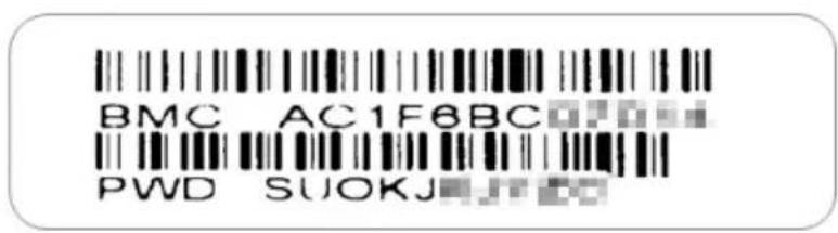
text_image
BMC AC1F6BC PWD SUOKJ1-3 Contacting Supermicro
Headquarters
Address: Super Micro Computer, Inc.
980 Rock Ave.
San Jose, CA 95131 U.S.A.
Tel: +1 (408) 503-8000
Fax: +1 (408) 503-8008
marketing@supermicro.com (General Information)
Email: support@supermicro.com (Technical Support)
Web Site: www.supermicro.com
Europe
Address: Super Micro Computer B.V.
's-Hertogenbosch, The Netherlands
Tel: +31 (0) 73-6400390
Fax: +31 (0) 73-6416525
sales@supermicro.nl (General Information)
Email: support@supermicro.nl (Technical Support)
rma@supermicro.nl (Customer Support)
Asia-Pacific
Address: Super Micro Computer, Inc.
3F, No. 150, Jian 1st Rd.
Zhonghe Dist., New Taipei City 23511
Taiwan (R.O.C)
Tel: +886-(2) 8226-3990
Fax: +886-(2) 8226-3992
Web Site: www.supermicro.com.tw
Technical Support:
Email: support@supermicro.com.tw
Tel: +886-(2)-8226-3990
Chapter 2 Standardized Warning Statements
2-1 About Standardized Warning Statements
The following statements are industry standard warnings, provided to warn the user of situations which have the potential for bodily injury. Should you have questions or experience difficulty, contact Supermicro's Technical Support department for assistance. Only certified technicians should attempt to install or configure components.
Read this appendix in its entirety before installing or configuring components in the Supermicro chassis
These warnings may also be found on our website at http://www.supermicro.com/about/policies/safety_information.cfm.
Warning Definition

Warning!
This warning symbol means danger. You are in a situation that could cause bodily injury. Before you work on any equipment, be aware of the hazards involved with electrical circuitry and be familiar with standard practices for preventing accidents.
警告の定義
この警告サインは危険を意味します。
Installation Instructions

Warning!
Read the installation instructions before connecting the system to the power source.
設置手順書
This product relies on the building's installation for short-circuit (overcurrent) protection. Ensure that the protective device is rated not greater than: 250 V,
20 A.
サーキット・ブレーカー
Power Disconnection Warning

Warning!
The system must be disconnected from all sources of power and the power cord removed from the power supply module(s) before accessing the chassis interior to install or remove system components.
電源切断の警告
Equipment Installation

Warning!
Only trained and qualified personnel should be allowed to install, replace, or service this equipment.
機器の設置
This unit is intended for installation in restricted access areas. A restricted access area can be accessed only through the use of a special tool, lock and key, or other means of security. (This warning does not apply to workstations).
アクセス制限区域
قالfundfundfund Fund Fund Fund Fund Fund Fund Fund Fund Fund Fund Fund Fund Fund Fund Fund Fund Fund Fund Fund Fund Fund Fund Fund Fund Fund Fund Fund Fund Fund Fund Fund Fund Fund Fund Fund Fund Fund Fund Fund Fund Fund Fund Fund Fund Fund Fund Fund Fund Fund Fund Fund Fund Fund Fund Fund Fund Fund Fund Fund Fund Fund Fund Fund Fund Fund Fund Fund Fund Fund Fund Fund Fund Fund Fund Fund Fund Fund Fund Fund Fund Fund Fund Fund Fund Fund Fund Fund Fund Fund Fund Fund Fund Fund Fund Fund Fund Fund Fund Fund Fund
경고!
There is the danger of explosion if the battery is replaced incorrectly. Replace the battery only with the same or equivalent type recommended by the manufacturer. Dispose of used batteries according to the manufacturer's instructions.
電池の取り扱い
.הכלההוּרָהוּרָהוּרָהוּרָהוּרָהוּרָהוּרָהוּרָהוּרָהוּרָהוּרָהוּרָהוּרָהוּרָהוּרָה
Redundant Power Supplies

Warning!
This unit might have more than one power supply connection. All connections must be removed to de-energize the unit.
冗長電源裝置
Hazardous voltage or energy is present on the backplane when the system is operating. Use caution when servicing.
バックプレーンの電圧
Comply with Local and National Electrical Codes

Warning!
Installation of the equipment must comply with local and national electrical codes.
地方および国の電気規格に準拠
Ultimate disposal of this product should be handled according to all national laws and regulations.
製品の廃棄
The fans might still be turning when you remove the fan assembly from the chassis. Keep fingers, screwdrivers, and other objects away from the openings in the fan assembly's housing.
ファン・ホットスワップの警告
Power Cable and AC Adapter

Warning!
When installing the product, use the provided or designated connection cables, power cables and AC adaptors. Using any other cables and adaptors could cause a malfunction or a fire. Electrical Appliance and Material Safety Law prohibits the use of UL or CSA-certified cables (that have UL/CSA shown on the code) for any other electrical devices than products designated by Supermicro only.
電源コードと AC アダプター
Chapter 3 Setup and Installation
3-1 Overview
This chapter covers the setup and installation of the MicroBlade module and its components.
3-2 Installing MicroBlade Modules
Up to twenty-eight MBI-6119M-T2N MicroBlade modules may be installed into a single MBE-628E-xxx enclosure, or up to fourteen in a MBE-314E-xxx MicroBlade module enclosure. MicroBlade modules with Windows and Linux operating systems may be mixed together in the same blade enclosure.
Powering Up a MicroBlade Module Unit
Each MicroBlade module unit may be powered on and off independently from the rest of the MicroBlade modules installed in the same enclosure. A MicroBlade module unit may be powered up in two ways:
- Press the power button on the MicroBlade module unit.
- Use IPMIView or the web-browser based management utility to apply power using the CMM MicroBlade module.
Powering Down a MicroBlade Module Unit
A MicroBlade module unit may be powered down in either of the following ways:
- Press the power button on the MicroBlade module unit.
- Use IPMIView or the web-browser based management utility to power down (if you have Operator or Admin privileges on the CMM).
- Use IPMItool when connected to the CMM to power down (if you have Operator or Admin privileges on the CMM).
Removing a MicroBlade Module Unit from the Enclosure
Although the MicroBlade module system may continue to run, individual MicroBlade modules should always be powered down before removing them from the enclosure.
Removing a MicroBlade Module Unit from the Enclosure
- Power down the MicroBlade module unit (see "Powering Down a MicroBlade Module Unit" above).
- Squeeze both handles to depress the red sections then pull out both handles completely and use them to pull the MicroBlade module unit from the enclosure.
Note: MicroBlade modules can be hot-plugged from the enclosure.
Installing a Blade Unit into the Enclosure
Use the procedure below to install a blade unit into an enclosure.
Installing a MicroBlade Module Unit into the Enclosure
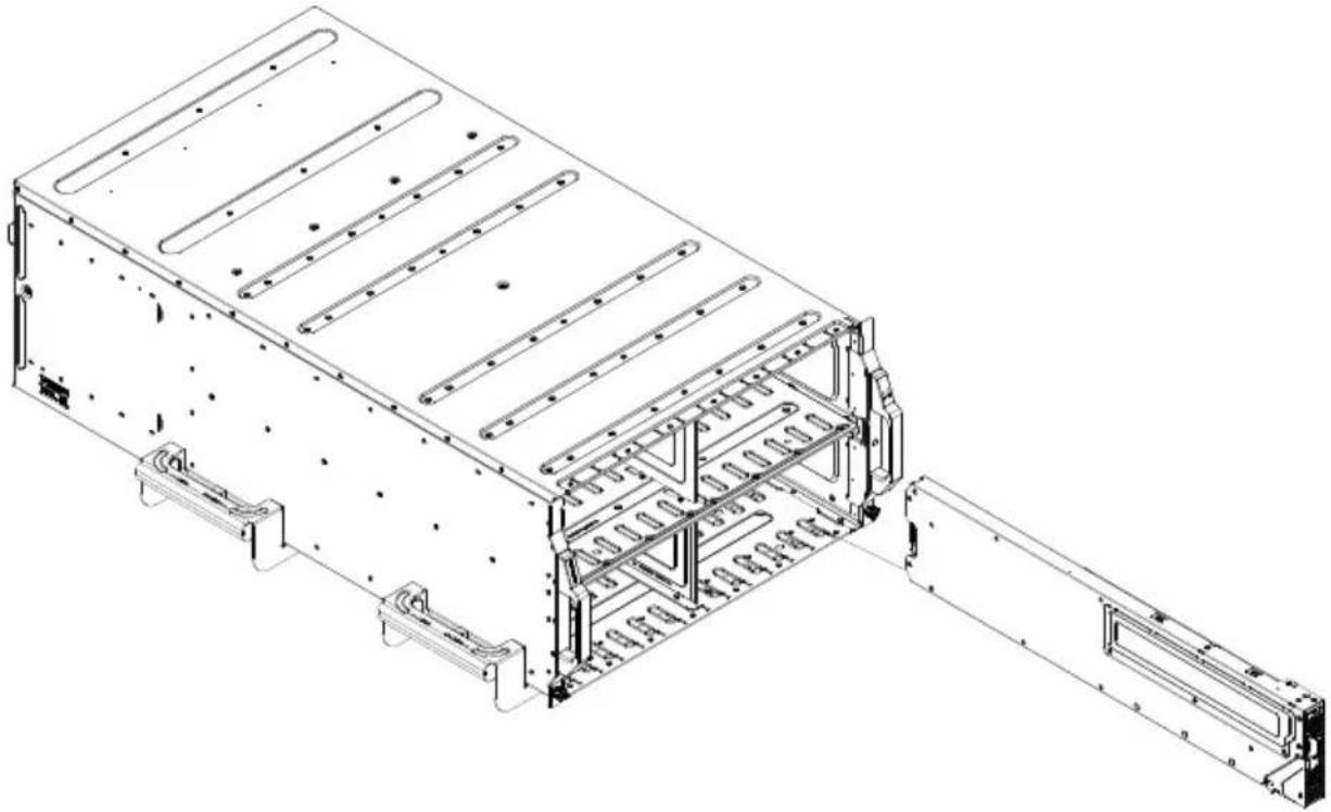
- Slowly push the MicroBlade module unit into its bay with the handles fully pulled out (see Figure 3-1).
- When the MicroBlade module stops, push the handles back in to their locked position, making sure the notches in both handles catch the lip of the enclosure.
Note: MicroBlade modules can be Hot-Plugged into the enclosure.
Caution: Use extreme caution when inserting a MicroBlade module into the enclosure. If the MicroBlade module's power connector becomes damaged, it can damage pins on other MicroBlade module bays that it is inserted into.
Figure 3-1. Inserting a MicroBlade Module into the Enclosure
natural_image
Technical line drawing of a modular electronic device with internal structural components and mounting brackets (no text or symbols)3-3 Onboard Battery Installation
A battery is included on the motherboard to supply certain volatile memory components with power when power has been removed from the MicroBlade module. If this battery dies, it must be replaced with an equivalent CR2032 Lithium 3V battery. Dispose of used batteries according to the manufacturer's instructions. See Figure 3-2 for a diagram of installing a new onboard battery.
Caution: There is a danger of explosion if the onboard battery is installed upside down, which reverses its polarities.
Figure 3-2. Installing the Onboard Battery

text_image
Lithium Battery Battery Holder3-4 Processor and Heatsink Installation
Follow the procedures in this section to install a processor (CPU) and heatsink to the motherboard.
Notes:
- The motherboard should be installed into the chassis first and the processor should be installed into the CPU socket before you install a CPU heatsink.
- If you bought a CPU separately, make sure that you use an Intel-certified multi-directional heatsink only.
- When receiving a motherboard without a processor pre-installed, make sure that the plastic CPU socket cap is in place and none of the socket pins are bent; otherwise, contact your retailer immediately.
• Refer to the Supermicro website for updates on CPU support.
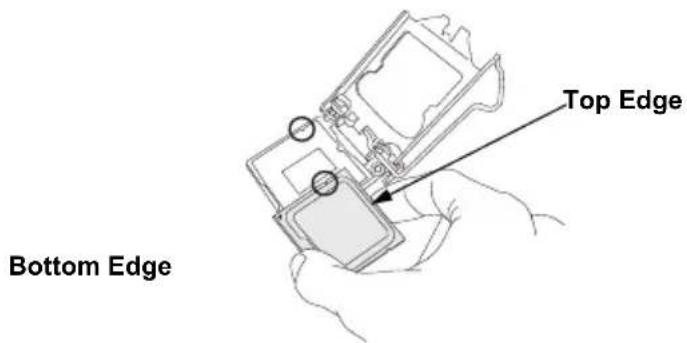
Installing the Processor(s)
Begin by removing power from the system.
- Remove the cover plate that protects the CPU#1 socket. Lift the lever on the socket until it points straight up. With the lever raised, lift open the processor retention plate.

text_image
Technical diagram showing two steps of a device or component with labeled arrows and directional arrows indicating movement or flow.- Gently lift the load lever to open the load plate. Remove the plastic cover plate.
-
Use your thumb and your index finger to hold the edges of the processor. Align the CPU key (the semi-circle cutouts) with the socket keys.
-
Once aligned, carefully place the processor into the socket. Do not drop the processor on the socket, move or rub the processor against the socket or against any socket pins, which may damage the components.

text_image
Pin 1- With the processor inserted into the socket, inspect the four corners of the CPU to make sure that it is properly installed and flush with the socket.

text_image
CPU Properly Installed Load Lever Locked into Place- Carefully press the processor load lever down until it locks into its retention tab.
Installing a Heatsink
An active type heatsink is used on the motherboard.
Note: You should apply thermal grease to the heatsink if it has not already been pre-applied.
- Place the heatsink on top of the CPU so that the four mounting holes are aligned with those on the heatsink retention mechanism.
- Screw in two diagonal screws (i.e. the #1 and the #2 screws) until they are just snug. Do not fully tighten the screws or you may damage the CPU.
- Add the two remaining screws then finish the installation by fully tightening all four screws (be careful not to overtighten).

text_image
Screw #1 Screw #2 Motherboard Mounting Holes Heatsink BracketNote: The images above is for illustrative purposes only.
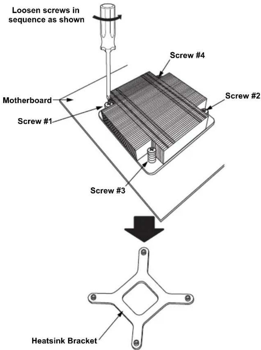
Removing a Heatsink
We do not recommend removing the heatsink. If necessary, please follow the instructions below to prevent damage to the CPU or the CPU socket.
- Unscrew and remove the heatsink screws from the motherboard in the sequence as show in the figure above.
- Hold and gently_ pivot the heatsink back and forth to loosen it from the CPU. (Do not use excessive force when dislodging the heatsink.).
- Once the heatsink is loose, remove it from the CPU.
- Clean the surface of the CPU and the heatsink to get rid of the old thermal grease. Reapply the proper amount of thermal grease to the surface before you re-install the heatsink.
text_image
Loosen screws in sequence as shown Screw #4 Screw #2 Motherboard Screw #1 Screw #3 Heatsink BracketNote: The images above is for illustrative purposes only.
Note: Wait for the heatsink to cool down before removing it.
3-5 Memory Installation
The mainboard of each blade unit must be populated with DIMMs (Dual In-line Memory Modules) to provide system memory. The DIMMs should all be of the same size and speed and from the same Super Micro authorized manufacturer due to compatibility issues. See details below on supported memory and our web site (http://www.supermicro.com/products/microblade/ for recommended memory.
Populating Memory Slots
The mainboard of a MBI-6119M-T2N MicroBlade module has four (4) memory slots. For optimized memory bandwidth it is strongly recommended that ALL memory slots in this MicroBlade module be populated by DIMMs. DIMM layout is shown below in Figure 3-3.
Figure 3-3. 4-slot DIMM Numbering

text_image
P1 DIMMA1 P1 DIMMA2 P1 DIMMB1 P1 DIMMB2Note: Though multiple DIMM memory module types and speeds may be supported, you need to use DIMM memory modules of the same speed and type.
DIMM Installation
Caution: Exercise extreme care when installing or removing DIMM modules to prevent any possible damage.
Installing DIMM Memory Modules
- Power down the blade module (see "Powering Down a MicroBlade Module Unit" on page 3-1).
- Remove the blade from the enclosure.
- Remove the air shroud that covers the DIMM slots.
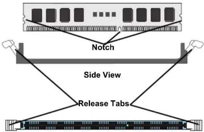
- Insert each DIMM vertically into its slot, starting with slots A1 and A2. Pay attention to the notch along the bottom of the module to prevent inserting the DIMM incorrectly (see Figure 3-4).
Figure 3-4. Installing a DIMM into a Memory Slot
To Install: Insert module vertically and press down until it snaps into place. Pay attention to the bottom notch.
To Remove: Use your thumbs to gently push each release tab outward to free the DIMM from the slot.
Note: The notch should align with the receptive key point on the
flowchart
graph TD
    A["Notch"] --> B["Side View"]
    B --> C["Release Tabs"]
    C --> A
Top View
- Gently press down on the DIMM until it snaps into place in the slot. Repeat for all modules.
- Replace the air shroud and install the blade module back into the enclosure.
- Power up the blade unit (see "Powering Up a MicroBlade Module Unit" on page 3-1).
3-6 Hard Disk Drive Installation
Up to two SATA3 HDD/SSD's or two NVMe/SATA3 HDD's 2.5" drives can be installed in the MicroBlade module, and cannot be removed or replaced without powering down the blade unit they reside in. A blade module needs a hard disk drive with an operating system installed to operate. RAID 0, 1 and 10 are supported.
3-7 Installing the Operating System
An operating system (OS) must be installed on each MicroBlade module. Blades with Microsoft Windows OS and blades with Linux OS can both occupy and operate within the same blade enclosure. Refer to the SuperMicro web site for a complete list of supported operating systems.
There are several methods of installing an OS to the blade modules.
Installing via PXE Boot
PXE (Preboot Execution Environment) is used to boot a computer over a network. To install the OS via PXE, the following conditions must be met:
- The PXE B 00T option in BIOS must be enabled.
- A PXE server has been configured (this can be another blade in the system).
- The PXE server must be connected over a network to the blade to be booted.
- The blade has only non-partitioned/unformatted hard drives installed and no bootable devices attached to it.
Once these conditions are met, make sure the PXE server is running. Then turn on the blade on which you wish to boot and/or install the OS. The BIOS in the blade will look at all bootable devices and finding none will connect to the PXE server to begin the boot/install.
Installing via Virtual Media (Drive Redirection)
You can install the OS via Virtual Media through either the IPMIview (Java based client utility), IPMItool or the Web-based Management Utility. With this method, the OS is installed from an ISO image that resides on another system/blade.
Chapter 4 MicroBlade Module Features
Figure 4-1. MBI-6119M-T2N Blade Unit Front View
natural_image
Internal view of a computer motherboard with drive bays and memory chips (no visible text or symbols)This chapter describes the MBI-6119M-T2N MicroBlade module. Installation and maintenance should be performed by experienced technicians only.
See Figure 4-1 for a front view of the blade unit and Table 4-1 for its features.
Table 4-1. MBI-6119M-T2N Blade Unit Features
| Feature Description | |
| Processors | Supports a single Intel Xeon Processor E-2100 series embedded in a H4 (LGA 1151) socket on the motherboard |
| Memory | Supports up to 64 GB of DDR4 2666 MHz speed and 16 GB size, 1.2 V voltage 2RX8 ECC VLP UDIMM memory in four (4) 288-pin DIMM sockets |
Table 4-1. MBI-6119M-T2N Blade Unit Features
| Feature Description | |
| Storage | Supports up to two SATA3 HDD/SSD's or two NVMe/SATA3 HDD's 2.5" drives |
| BIOS 128 Mb SPI Flash EEPROM with AMI® BIOS | |
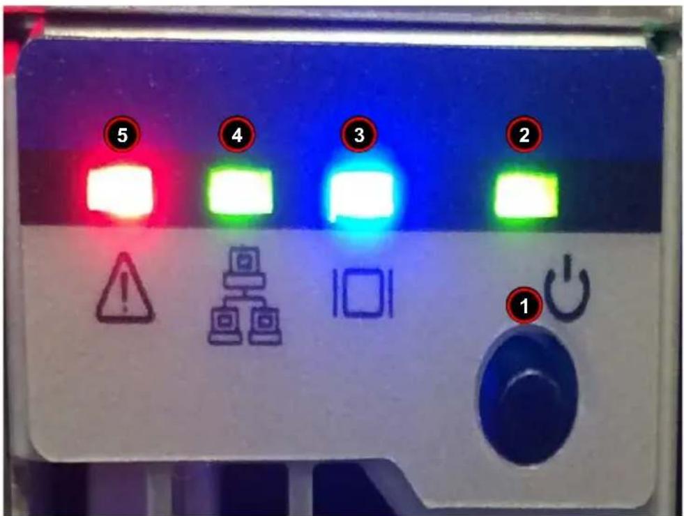
4-1 Control Panel
Each MicroBlade module has a similar control panel (Figure) with power on/off button, reset button and LEDs on the front left side of the module. The numbers mentioned in Figure are described in Table 4-2.
Figure 4-2. Blade Control Panel
text_image
5 4 3 2 1Table 4-2. Blade Control Panel
| Item | Function State | Description | |
| 1 Power Button N/A Turns | MicroBlade module on and off | ||
| 2 Power LED | Green Indicates power status “On” | ||
| Amber | Before the BMC is ready, the Amber LED will blink until the last node is ready. | ||
| 3 | KVM/UID LED (Blue) | Steady On Indicates that KVM has been initialized on this blade module | |
| Flashing | Serves as a UID indicator (the UID function is activated with a management program) | ||
| 4 | Network LED (Green) | Flashing Green | Flashes on and off to indicate traffic (Tx and RX data) on the LAN connection to this blade module. |
| Network LED (Orange) | Flashing Orange | Flashes on and off to indicate traffic over the network (when present in the system) | |
| 5 | System Fault LED (Red) | Steady On | This LED illuminates red when a fatal error occurs. This may be the result of a memory error, or any other fatal error that prevents the operating system from booting up. |
Power Button
Each MicroBlade module has its own power button so that individual blade units within the enclosure may be turned on or off independently of the others. Press the power button (#1) to turn on the blade server. The power LED (#3) will turn green. To turn off, press and hold the power button for >4 seconds and the power LED will turn orange.
LED Indicators
Blade module LEDs are described below in Table 4-3.
Table 4-3. Blade Module LED Indicators
| LED State Description | ||
| Power LED | Green Power OnAmber StandbyRed Power Failure | |
| System Fault LED (Red) | Steady On | This LED illuminates red when a fatal error occurs. This may be the result of a memory error, or any other fatal error that prevents the operating system from booting up. |
4-2 Motherboard
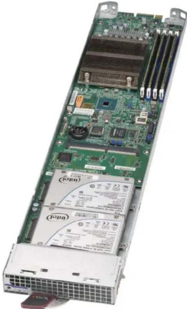
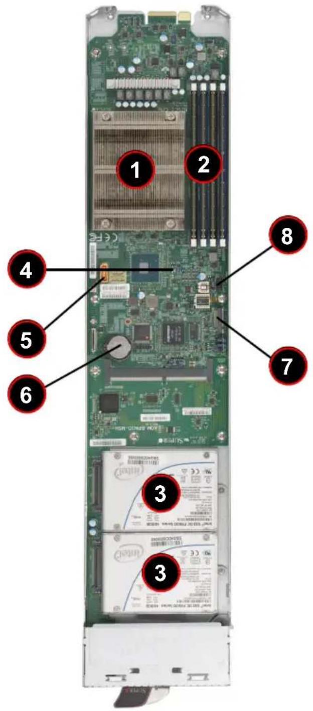
The motherboard of the MBI-6119M-T2N MicroBlade module unit is a proprietary design, which is based on the Intel Xeon Processor E-2100 series processor. See Figure 4-4 for a block diagram of this chipset, Figure 4-3 for a view of the B2SC1-CPU motherboard and Figure 4-5 for an exploded view diagram of the MicroBlade module unit.
Figure 4-3. B2SC1-CPU Motherboard
text_image
Internal view of a computer tower with numbered components and labeled parts in ChineseTable 4-4. B2SC1-CPU Motherboard Layout
| Item Description | |
| 1 Intel Xeon Processor E-2100 series processors embedded in a H4 (LGA 1151) socket | |
| 2 DIMM slots for DIMM memory modules | |
| 3 2.5" SATA3/NVMe/SSD/HDD's | |
| 4 CMOS Clear | |
| 5 | S A T A D O M P |
| 6 Battery | |
| 7 M.2 PCI-E SATA connector | |
| 8 TMP connector | |
Figure 4-4. Intel B2SC1-CPU Block Diagram
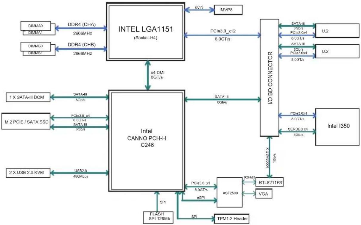
flowchart
graph TD
    A["INTEL LGA1151 (Socket-H4)"] -->|SVID| B["IMVP8"]
    A -->|x4 DMI 8GT/s| C["Intel CANNO PCH-H C246"]
    A -->|PCIe3.0_x12 8.0GT/s| D["I/O BD CONNECTOR"]
    D -->|SATA-II 0Gb/s PCle3.0x4 8.0GT/s SATA-II 6Gb/s PCIe3.0x4 8.0GT/s U.2| E["U.2"]
    D -->|SATA-II 0Gb/s PCle3.0x4 8.0GT/s SATA-II 6Gb/s PCIe3.0x4 8.0GT/s U.2| F["Intel I350"]
    D -->|SATA-II 6Gb/s| G["RTL8211FS"]
    D -->|PCIe3.0x4 8.0GT/s SERDES x4 6Gb/s| H["PTM1.2 Header"]
    D -->|PCIe3.0x4 8.0GT/s eSPI| I["AST2500"]
    I --> J["FLASH SPI 128Mb"]
    I --> K["USB2.0 480Mbps"]
    I --> L["2X USB 2.0 KVM"]
    A --> M["DDR4 (CHA) 2666MHz"]
    A --> N["DDR4 (CHB) 2666MHz"]
    A --> O["DIMMA0 DIMMA1"]
    A --> P["DIMMB0 DIMMB1"]
Jumpers
Any jumpers present on the motherboard are used by the manufacturer only; there are no jumpers used to configure the operation of the motherboard by the user.
CMOS Clear
JBT1 is used to clear CMOS and will also clear any passwords. JBT1 consists of two contact pads located near the BIOS chip.
Clearing CMOS
- First power down the blade and remove it from the enclosure.
- Short the CMOS pads with a metal object such as a small screwdriver.
- Install the blade back into the enclosure and power it on.
4-3 Blade Unit Components
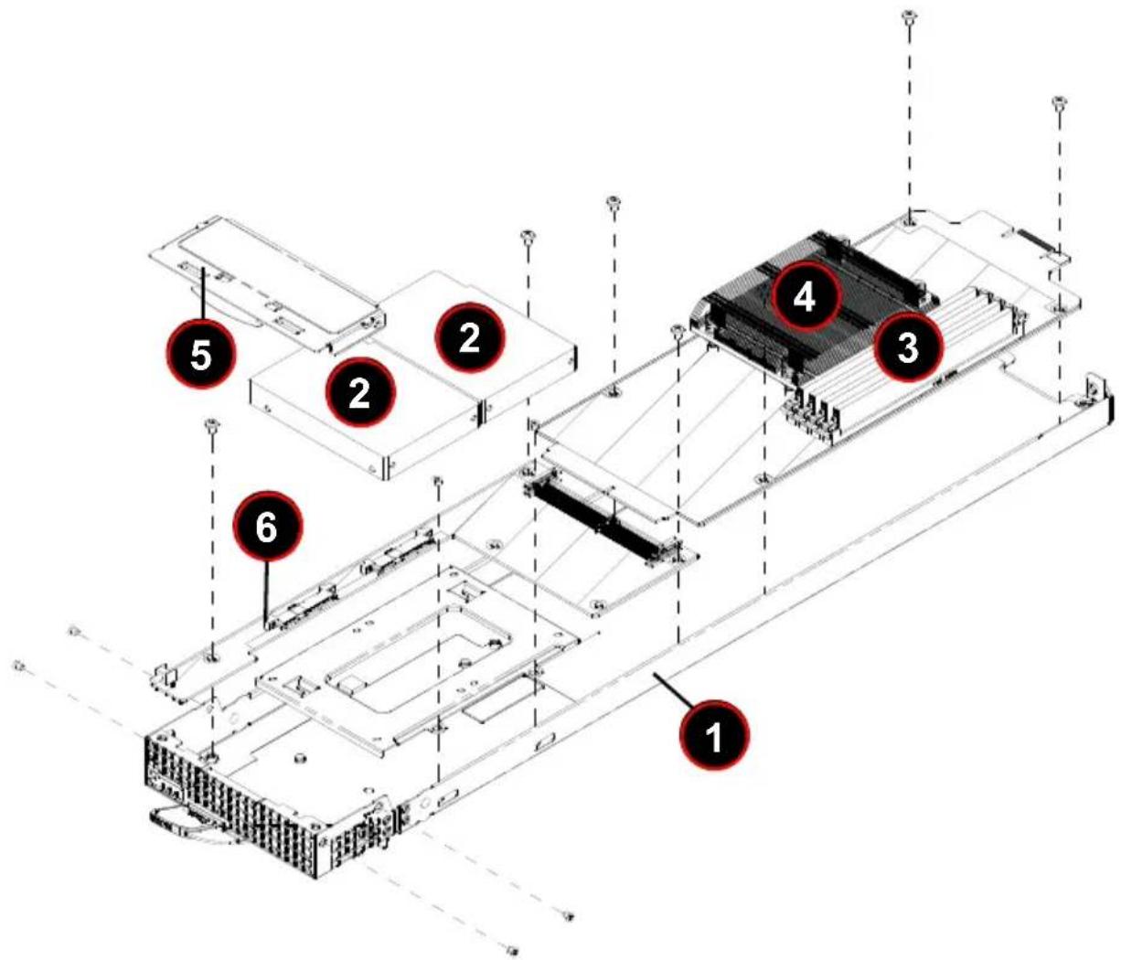
Figure 4-5. Exploded View of a MBI-6119M-T2N MicroBlade Module
text_image
1 2 3 4 5 6 2 3 6Table 4-5. Main Components of a MBI-6119M-T2N Blade Module
| Item Description |
| 1 Blade Unit/Module |
| 2 2.5" Hard Drives (2) |
| 3 DIMM slots (4) |
| 4 CPU/Heatsink |
| 5 Top Cover |
| 6 Hard Drive Backplane |
Memory Support
The MBI-6119M-T2N MicroBlade module supports up to 64 GB of 2RX8 ECC VLP UDIMM, 16 GB size DIMM memory in four (4) sockets. See Section 3-5: Memory Installation on page 3-8 for further details on motherboard memory installation.
Hard Disk Drives
The MBI-6119M-T2N MicroBlade module accommodates up to two SATA3 HDD/SSD's or two NVMe/SATA3 HDD's 2.5" drives. The drives cannot be removed or replaced without powering down the blade unit they reside in. See Chapter 1 for information on RAID Setup.
WARNING: Enterprise level hard disk drives are recommended for use in Supermicro chassis and servers. For information on recommended HDDs, visit the Supermicro Web site at http://www.supermicro.com/products/nfo/storage.cfm
Chapter 5 BIOS
5-1 Introduction
This chapter describes the BIOS for the MBI-6119M-T2N MicroBlade module. This MicroBlade module uses a 128 Mb SPI Flash EEPROM with AMI® BIOS™ that is stored in a flash chip. This BIOS can be easily upgraded using a floppy disk-based program.
Note: Due to periodic changes to the BIOS, some settings may have been added or deleted and might not yet be recorded in this manual. Please refer to the http://www.supermicro.com/products/microblade/module/web site for further details on BIOS setup and the BIOS menus for your MicroBlade module.
System BIOS
BIOS stands for Basic Input Output System. The 128 Mb SPI Flash EEPROM with AMI® BIOS BIOS flash chip stores the system parameters, types of disk drives, video displays, in the CMOS. The CMOS memory requires very little electrical power. When the blade unit is turned off, a backup battery provides power to the BIOS flash chip, enabling it to retain system parameters. Each time the blade is powered on it is configured with the values stored in the BIOS ROM by the system BIOS, which gains control at boot up.
How To Change the Configuration Data
The CMOS information that determines the system parameters may be changed by entering the BIOS Setup utility. This Setup utility can be accessed by pressing the
Starting the Setup Utility
Normally, the only visible POST (Power-On Self-Test) routine is the memory test. As the memory is being tested, press the
Caution: To prevent possible boot failure, do not shut down or reset the system while updating the BIOS.
5-2 BIOS Updates
It may be necessary to update the BIOS used in the blade modules on occasion. However, it is recommended that you not update BIOS if you are not experiencing problems with a blade module.
Updated BIOS files are located on our web site (http://www.supermicro.com/products/microblade). Please check the current BIOS revision and make sure it is newer than the revision you have.
To upload a new BIOS update, simply follow the Help instructions in the IPMI BIOS Upload page (Figure 5-1) when you press the Help button at the top of the page. This procedure will get you a BIOS Update.
Figure 5-1. IPMI BIOS Upload Page with Help Upload Procedure

text_image
SuperMicking Host Identification Server: 172.031.936.170 User: ADMIN (Administrator) System Server Health Configuration Remote Control Virtual Media Maintenance Miscellaneous Help Maintenance Firmware Update Unit Reset IKVMI Reset Factory Default IPMI Configuration System Event Log BIOS Update BIOS Upload The device is now in BIOS Update mode. Please upload your BIOS image for updating. Node Product Key status : Activated Node Product Key : Select BIOS image to upload Browse... No file selected. Upload BIOS Cancel Help : Node Product Key To update BIOS, follow the instructions below. 1. Check Node Product Key status. If key status is inactive, enter product key to activate the bios license. 2. Upload the desired BIOS image by clicking [Choose File]. 3. Click [Update BIOS] to begin the updating process. 4. Check the following options if you want to make any preservation: • ME region (Management Engine) • NVRAM (Non-volatile Random-Access Memory) • SMBIOS (System Management BIOS) 5. Click [Start Upgrade] to initiate the process. ""[Warning]": Once the server is in the update mode, BIOS will reset in order to go back to normal operating mode even if you abort the update process. Copyright © 2014 Super Micro Computing, Inc.5-3 Running Setup
Note: Default settings are in bold text unless otherwise noted.
The BIOS setup options described in this section are selected by choosing the appropriate text from the MAIN BIOS SETUP screen. All displayed text is described in this section, although the screen display is often all you need to understand how to set the options.
When you first power on the computer, the BIOS is immediately activated.
While the BIOS is in control, the Setup program can be activated in one of two ways:
- By pressing
immediately after turning the system on, or - When the message Press the
key to enter Setup appears briefly at the bottom of the screen during the POST, press the key to activate the main SETUP menu:
5-4 Main BIOS Setup
Figure 5-2. BIOS Setup Screen
| System Date System Time Supermicro B28C1-CPU BIOS Version Build Date CPLD Version Memory Information Total Memory Memory Speed | [Tue 11/06/2018] [23:39:03] | Set the Date, Use Tab to switch between Date elements. Default Ranges: Year: 2005-2039 Months: 1-12 Days: dependent on month |
| 1.0 10/16/2018 04.60.86 | ||
| 32758 MB 2400 MHz | +: Select Screen ↑↓: Select Item Enter: Select +/-: Change Opt. F1: General Help F2: Previous Values F3: Optimized Defaults F4: Save & Exit ESC: Exit |
All Main Setup options are described in this section. Use the UP/DOWN arrow keys to move among the different settings in each menu. Use the LEFT/RIGHT arrow keys to change the options for each setting. Press the
Menu options found in the MAIN BIOS SETUP menu are described in Table 5-1.
Table 5-1. Main BIOS Setup Menu Options
| Menu Option Description | |
| System Date | Using the arrow keys, highlight the month, day and year fields, and enter the correct data for the system date. Press thekey to save the data. |
| System Time | To set the system date and time, key in the correct information in the appropriate fields. Then press thekey to save the data. |
| BIOS Information | BIOS static display information including the motherboard number, SMC version, SMC Build Date and Memory Information is also shown on the screen. |
5-5 Advanced Setup
Figure 5-3. Advanced Setup Screen
| Aptio Setup Utility - Copyright (C) 2018 American Megatrends, Inc. Main Advanced Event Logs IPMI Security Boot Save & Exit | |
| Boot Feature CPU Configuration Chipset Configuration Super ID Configuration Serial Port Console Redirection SATA And RSTe Configuration PCH-FW Configuration ACPI Settings USB Configuration PCIe/PCI/PnP Configuration Trusted Computing NVMe Configuration ISCSI Configuration Tls Auth Configuration | Boot Feature Configuration Page |
| ++: Select Screen ↑↓: Select Item Enter: Select +/-: Change Opt. F1: General Help F2: Previous Values F3: Optimized Defaults F4: Save & Exit ESC: Exit | |
| Version 2.20.1271. Copyright (C) 2018 American Megatrends, Inc. | |
Choose Advanced from the BIOS Setup Utility main menu with the arrow keys to display the ADVANCED SETUP menu. The items with a triangle beside them are sub-menus that can be accessed by highlighting the item and pressing
Table 5-2 describes all sub-menus found in the ADVANCED SETUP menu.
Table 5-2. Advanced Setup Menu Options
| Sub-menu Description | |
| ►Boot Feature | See Table 5-3 for a description of BIOS setup menu options in this sub-menu. |
| ►CPU Configuration | See Table 5-4 for a description of BIOS setup menu options in this sub-menu. |
| ►Chipset Configuration | See Table 5-5 for a description of BIOS setup menu options in this sub-menu. |
| ►Super IO Configuration | See Table 5-6 for a description of BIOS setup menu options in this sub-menu. |
| ►Serial Port Console Redirection | See Table 5-7 for a description of BIOS setup menu options in this sub-menu. |
| ►SATA and RSTe Configuration | See Table 5-8 for a description of BIOS setup menu options in this sub-menu. |
| ►PCH-FW Configuration | See Table 5-9 for a description of BIOS setup menu options in this sub-menu. |
| ►ACPI Settings | See Table 5-10 for a description of BIOS setup menu options in this sub-menu. |
| ►USB Configuration | See Table 5-11 for a description of BIOS setup menu options in this sub-menu. |
| ►PCIe/PCI/PnP Configuration | See Table 5-12 for a description of BIOS setup menu options in this sub-menu. |
| ►Trusted Computing | See Table 5-13 for a description of BIOS setup menu options in this sub-menu. |
| ►NVMe Configuration | See Table 5-14 for a description of BIOS setup menu options in this sub-menu. |
| ►iSCSI Configuration | See Table 5-15 for a description of BIOS setup menu options in this sub-menu. |
| ►T1s Auth Configuration | See Table 5-16 for a description of BIOS setup menu options in this sub-menu. |
Table 5-3. Boot Feature Sub-menu
| Menu Option Description | |
| Quiet Boot | Use this feature to select the screen display between the POST messages and the OEM logo upon bootup. Select Disabled to display the POST messages. Select Enabled to display the OEM logo instead of the normal POST messages. The options areEnabledand Disabled. |
| Option ROM Messages | Use this feature to set the display mode for the Option ROM. Select Keep Current to display the current AddOn ROM setting. Select Force BIOS to use the Option ROM display set by the system BIOS. The options areForce BIOSand Keep Current. |
| Bootup NumLock State | Use this feature to set the Power-on state for thekey. The options are Off andOn. |
| Wait for 'F1' If Error | Use this feature to force the system to wait until the 'F1' key is pressed if an error occurs. The options are Disabled andEnabled. |
| INT19 Trap Response | Interrupt 19 is the software interrupt that handles the boot disk function. When this item is set to Enabled, the ROM BIOS of the host adaptors will "capture" Interrupt 19 at bootup and allow the drives that are attached to these host adaptors to function as bootable disks. If this item is set to Disabled, the ROM BIOS of the host adaptors will not capture Interrupt 19, and the drives attached to these adaptors will not function as bootable devices. The options areImmediateand Postponed. |
| Re-try Boot | This option allows you to decide how to retry boot devices which fail to boot. Options includeDisabled, Legacy Boot or EFI Boot. |
| Watch Dog Function | If enabled, the Watch Dog Timer will allow the system to reboot when it is inactive for more than 5 minutes. The options are Enabled andDisabled. |
| Power Button Function | This feature controls how the system shuts down when the power button is pressed. Select 4_Seconds_Override for the user to power off the system after pressing and holding the power button for 4 seconds or longer. Select Instant Off to instantly power off the system as soon as the user presses the power button. The options are 4 Seconds Override andInstant Off. |
Table 5-4. CPU Configuration Sub-menu
| Menu Option Description | |
| Processor Information Static | processor information is displayed at the top of the menu. |
| Internal Graphics | Use this setting to configure IGFX. Options include Auto, Disabled and Enabled. |
| CPU Flex Ratio Override | Use this setting to Enable/Disable CPU Flex Ratio Programming. |
| CPU Flex Ratio Settings | This setting is activated when CPU Flex Ratio Override is enabled. The value in the field must be between the Max Efficiency Ratio (LFM) and the maximum non-turbo ratio set by the hardware (HFM). Default is 33. |
| Hardware Prefetcher | Use this feature to turn on/off the Mid Level Cache (L2) streamer prefetcher. Options include either Enable or Disable. |
| Adjacent Cache Line Prefetch | Use this feature to turn on/off prefetching of adjacent cache lines. Options include either Enable or Disable. |
| Intel (VMX) Virtualization Technology | When this feature is enabled, a VMM can utilize the additional hardware capabilities provided by Vanderpool Technology. Options include Enabled and Disabled. |
| Active Processor Cores | Use this feature to specify the number of cores to enable in each processor package. Options include All, 1, 2 and 3. |
| Hyper-threading | This setting is enabled for Windows XP and Linux and OS systems that are optimized for Hyper-threading technology. It is disabled for other OS that are not optimized for Hyper-threading technology. When Disabled only one thread per enabled core is enabled. Options are Enabled and Disabled. |
| Menu Option Description | |
| BIST | This feature allows you to Enable/Disable BIST (Built-In Self Test) on reset. |
| AES | This feature allows you to Enable/Disable Advanced Encryption Standard (AES) instructions. |
| ►CPU-Power Management Control Sub-menu | This sub-menu contains settings for CPU-Power Management Control. |
| Boot Performance Mode | This feature allows you to select the performance state that the BIOS will set before OS handoff. Options include Power Saving, Max Non-Turbo Performance and Turbo Performance. |
| Intel (R) SpeedStep (tm) | This feature allows you to specify more than two frequency ranges to be supported. Options include Enabled or Disabled. |
| Intel (R) Speed Shift Technology | This feature Enables/Disables Intel Speed Shift Technology support. Enabling will expose the CPPC v2 interface to allow for hardware controlled P-states. |
| Turbo Mode | This feature Enables or Disables Turbo Mode for your system. |
| MonitorMWait | Use this setting to Enable/Disable the performance state that the BIOS will set starting from the reset vector. |
| CPU C-States | This feature Enables or Disables CPU C-states. |
| Enhanced C-States | This feature enables or disables C1E. When Enabled, the CPU will switch to a minimum speed when all cores enter C-State. |
| C-State Auto Demotion | This feature configures C-State Auto Demotion. Options include Disabled, C1, C3 or C1 and C3. |
| C-State Un-Demotion | This feature configures C-State Un-demotion. Options include Disabled, C1, C3 or C1 and C3. |
| Package C-State Demotion | This feature allows you to Enable or Disable C-State Demotion for your system. |
| Package C-State Un-Demotion | This feature allows you to Enable or Disable C-State Un-demotion for your system. |
| Package C-State Limit | Use this feature to package a C-State Limit. Options include C0/C1, C2, C3, C6, C7, C7s, C8 and Auto. |
| Thermal Monitor | This feature allows you to Enable or Disable the Thermal Monitor feature for your system. |
| Interrupt Redirection Mode Selection | Use this feature to select for Logical Interrupts. Options include the following:Fixed PriorityRound RobinHash VectorPair with Fixed PriorityPair with Round RobinPair with Hash VectorNo Change |
| Timed MWAIT | This feature allows you to Enable or Disable Timed MWAIT Support. |
| ►Custom P-state Table | This sub-menu allows you to specify custom P-states. |
| Number of P-states | This sets the number of custom P-states. At least 2 states must be present, default is 0. |
| Energy Performance Gain | This feature allows you to Enable or Disable Energy Performance Gain on your system. EPG DIMM ldd3N and ldd3P information is displayed below this menu option. |
| EPGB DIMM ldd3N | This enables/disables the Energy Performance Gain for DIMM ldd3N, when Energy Performance Gain is enabled. |
| EPGB DIMM ldd3P | This enables/disables the Energy Performance Gain for DIMM ldd3P, when Energy Performance Gain is enabled. |
| ►Power Limit 3 Settings | This sub-menu allows you to specify Power Limit 3 Settings. |
| Power Limit 3 Override | This feature Enables/Disables Power Limit 3 Override. If this option is disabled, BIOS will program the default values for Power Limit 3 and Power 3 Time Window. |
| ►CPU Lock Configuration | This sub-menu allows you to specify CPU Lock Configuration. |
| CFG Lock | This feature Enables/Disables the MSR 0xE2[15], CFG and Lock Bit for the system. |
| Overclocking Lock | This feature Enables/Disables Overclocking Lock (BIT 20) in FLEX_RATIO(194) MSR. |
Table 5-5. Chipset Configuration Sub-menu
| Menu Option Description | |
| ►System Agent (SA)Configuration | This sub-menu allows you to configure System Agent (SA) parameters. |
| System AgentConfigurationInformation | This static display shows static information for the system agent configuration. |
| ►Memory Configuration | This sub-menu displays and provides options to change the memory settings. |
| MemoryConfigurationInformation | This static display shows memory configuration information for the memory configuration. |
| Maximum MemoryFrequency | Use this setting to restrict the maximum memory frequency below the enforced POR. Frequencies you can select range from 1333 ~ 3200 andAuto. DO NOT select Reserved from the list. |
| ECC Support | This setting is used toEnable/Disable DDR ECC Support. |
| Max TOLUD | This feature allows you to specify the maximum value of TOLUD. Selecting theDynamicassignment would adjust TOLUD automatically based upon the largest MMIO length of the installed graphic controller. Options includeDynamicand values from 1 GB ~ 3.5 GB. |
| Memory Scrambler | This featureEnablesor Disables Memory Scrambler support. |
| Fast Boot | This featureEnablesor Disables fast path through the MRC. |
| REFRESH_2X_MODE | Use this feature to select options for enabling or disabling refreshing 2X mode. Options includeDisabled, 1-Enabled for WARM or HOT and 2-Enabled for HOT only. |
| ►DMI/OPIConfiguration | This sub-menu displays options for DMI/OPI Configuration. |
| DMI Information This | static display shows DMI Information. |
| DMI Link ASPMControl | This setting enables/disables the control of the Active State Power Management on the SA side of the DMI link. Options include Disabled, L0s, L1and L0sL1. |
| DMI Extended SyncControl | Use this feature to Enable orDisableDMI Extended Synchronization for your system. |
| DMI D-EmphasisControl | Use this feature to configure the De-emphasis control on DMI. Options include -6 dB or -3.5 dB. |
| ►PEG PortConfiguration | This sub-menu displays options for PEG Port Configuration. |
| PEG 0:1:0 This shows | static information for the system PCI-E slot used. |
| Enable Root Port | Use this feature to Enable or Disable the PEG 0:1:0 Root Port. Options includeAuto, Disabled or Enabled. |
| Max Link Speed | Use this feature to configure PEG 0:1:0 Max Speed. Options includeAuto, Gen1, Gen2 and Gen3. |
| Max Link Width | Use this feature to configure the PEG link to retrain to X1/2/4/8. Options includeAuto, Force X1, Force X2, Force X4 and Force X8. |
| ASPM | Use this feature to control ASPM support for the PEG0. This has no effect if PEG is not the currently active device. Options include Disabled, Auto, ASPM L0s, ASPM L1, ASPM L0sL1. |
| De-emphasisControl | Use this feature to configure the De-emphasis control on PEG. Options include -6 dB and -3.5 dB. |
| PEG0 SlotPower LimitValue | Use this number field to set the upper limit on power supplied by the slot. The power limit (in Watts) is calculated by multiplying this value by the slot's Power Limit Scale. Values range from 0-255 with a default of75. |
| PEG0 SlotPower LimitScale | Use this feature to select the scale used for the Slot Power Limit Value. Options include 1.0x, 0.1xm, 0.01x and 0.001x. |
| PEGO PhysicalSlot Number | This feature sets the physical slot number attached to this port. The number has to be globally unique with the chassis. Values in this field are between 0 and 8191. Default is 1. |
| PEG0 MaxPayload Size | Use the feature to select the PEG0 Max Payload Size. Options includeAuto, 128 TLP and 256 TLP. |
| PEG 0:1:1 This shows | static information for the Onboard Lan1/2 i350 system. |
| Enable Root Port | Use this feature to Enable or Disable the PEG 0:1:1 Root Port. Options includeAuto, Disabled or Enabled. |
| Max Link Speed | Use this feature to configure PEG 0:1:1 Max Speed. Options includeAuto, Gen1, Gen2 and Gen3. |
| PEG1 Slot Power Limit Value | Use this number field to set the upper limit on power supplied by the slot. The power limit (in Watts) is calculated by multiplying this value by the slot's Power Limit Scale. Values range from 0-255 with a default of75. |
| PEG1 Slot Power Limit Scale | Use this feature to select the scale used for the Slot Power Limit Value. Options include1.0x, 0.1xm, 0.01x and 0.001x. |
| PEG1 Physical Slot Number | This feature sets the physical slot number attached to this port. The number has to be globally unique with the chassis. Values in this field are between 0 and 8191. Default is2. |
| Program PCIe ASPM After OPROM | Use this feature to enable/disable the Program PCIe ASPM after OPROM. WhenEnabled, the PCIe ASPM will be programmed after OPROM. If Disabled, the PCIe ASPM will be programmed before OPROM. |
| VT-d | Use this feature toEnable/Disable VT-d capability for your system. |
| GNA Device (B0:D8:F0) | Use this feature toEnable/Disable the SA GNA device. |
| X2APIC Opt Out | Use this feature toEnable/Disable the X2APIC_OPT_OUT bit.. |
| ▶PCH-IO Configuration This | sub-menu allows you to configure PCH-IO parameters. |
| PCIe PLL SSC setting This static setting shows the PCI-E PLL SCC setting. | |
| DMI Link ASPM Control | This feature is used to control the Active State Power Management of the DMI Link. Options include Disabled, L0s, L1, L0sL1 andAuto. |
| Peer Memory Write Enable | This feature allows you toDisable/Enable Peer Memory Write. |
| M.2-H_1 ASPM Support | This feature allows you to set the M.2-H_1 ASPM settings. Options include Disabled, L0s, L1, L0sL1 andAuto. |
| M.2-H_1 Substates | This feature allows you to set PCI-E L1 substates settings. Options include Disabled, L1.1 and L1.1 & L1.2. |
| M.2-H_1 PCIe Speed | This feature configures the PCI-E speed. Options includeAuto, Gen1, Gen2 and Gen3. |
Table 5-6. SuperIO Device Configuration Sub-menu
| Menu Option Description | |
| Super IO Chip | This static display shows the name of the Super IO chip installed for your system. |
| ▶Serial Port 1Configuration | This sub-menu allows the user the configure settings of Serial Port 1. |
| Serial Port 1 | Select Enabled to enable the a selected onboard serial port. The options are Enabled and Disabled. |
| Device Settings | This item displays the status of a serial part specified by the user. |
| Change Settings | This feature specifies the base I/O port address and the Interrupt Request address of a serial port specified by the user. Select Auto to allow the BIOS to automatically assign the base I/O and IRQ address.The options for Serial Port 1 areAuto, (IO=3F8h; IRQ=4), (IO=3F8h; IRQ=3, 4, 5, 6, 7, 9, 10, 11, 12), (IO=2F8h; IRQ=3, 4, 5, 6, 7, 9, 10, 11, 12), (IO=3E8h; IRQ=3, 4, 5, 6, 7, 9, 10, 11, 12) and (IO=2E8h; IRQ=3, 4, 5, 6, 7, 9, 10, 11, 12). |
| ▶Serial Port 2Configuration | This sub-menu allows the user the configure settings of Serial Port 1. |
| Serial Port | Select Enabled to enable the a selected onboard serial port. The options areEnabledand Disabled. |
| Device Settings | This item displays the status of a serial part specified by the user. |
| Change Settings | This feature specifies the base I/O port address and the Interrupt Request address of a serial port specified by the user. Select Auto to allow the BIOS to automatically assign the base I/O and IRQ address.The options for Serial Port 2 areAuto, (IO=2F8h; IRQ=3), (IO=3F8h; IRQ=3, 4, 5, 6, 7, 9, 10, 11, 12), (IO=2F8h; IRQ=3, 4, 5, 6, 7, 9, 10, 11, 12), (IO=3E8h; IRQ=3, 4, 5, 6-7, 9, 10, 11, 12) and (IO=2E8h; IRQ=3, 4, 5, 6, 7, 9, 10, 11, 12). |
| Serial Port 2 Attribute | Use this feature to select the serial port 2 mode. Options includeSOLand COM. |
Table 5-7. Serial Port Console Redirection Sub-menu
| Menu Option Description | |
| COM1 Console Redirection | Select Enabled to enable console redirection support for the COM1 serial port. The options are Enabled and Disabled. |
| SOL Console Redirection | Select Enabled to enable console redirection support for SOL. The options are Enabled and Disabled. |
| ►Console Redirection Settings (Both COM1 and SOL) | This feature allows the user to specify how the host computer will exchange data with the client computer, which is the remote computer used by the user. |
| Terminal Type | This feature allows the user to select the target terminal emulation type for Console Redirection. Select VT100 to use the ASCII Character set. Select VT100+ to add color and function key support. Select ANSI to use the Extended ASCII Character Set. Select VT-UTF8 to use UTF8 encoding to map Unicode characters into one or more bytes. The options are ANSI, VT100, VT100+, and VT-UTF8. |
| Bits Per second | Use this feature to set the transmission speed for a serial port used in Console Redirection. Make sure that the same speed is used in the host computer and the client computer. A lower transmission speed may be required for long and busy lines. The options are 9600, 19200, 38400, 57600 and 115200 (bits per second). |
| Data Bits | Use this feature to set the data transmission size for Console Redirection. The options are 7 Bits and 8 Bits. |
| Parity | A parity bit can be sent along with regular data bits to detect data transmission errors. Select Even if the parity bit is set to 0, and the number of 1's in data bits is even. Select Odd if the parity bit is set to 0, and the number of 1's in data bits is odd. Select None if you do not want to send a parity bit with your data bits in transmission. Select Mark to add a mark as a parity bit to be sent along with the data bits. Select Space to add a Space as a parity bit to be sent with your data bits. The options are None, Even, Odd, Mark and Space. |
| Stop Bits | A stop bit indicates the end of a serial data packet. Select 1 Stop Bit for standard serial data communication. Select 2 Stop Bits if slower devices are used. The options are 1 and 2. |
| Flow Control | Use this feature to set the flow control for Console Redirection to prevent data loss caused by buffer overflow. Send a “Stop” signal to stop sending data when the receiving buffer is full. Send a “Start” signal to start sending data when the receiving buffer is empty. The options are None and Hardware RTS/CTS. |
| VT-UTF8 Combo Key Support | Select Enabled to enable VT-UTF8 Combination Key support for ANSI/VT100 terminals. The options are Enabled and Disabled. |
| Recorder Mode | Select Enabled to capture the data displayed on a terminal and send it as text messages to a remote server. The options are Disabled and Enabled. |
| Resolution 100x31 | Select Enabled for extended-terminal resolution support. The options are Disabled and Enabled. |
| Putty KeyPad | This feature selects the settings for Function Keys and KeyPad used for Putty, which is a terminal emulator designed for the Windows OS. The options are VT100, LINUX, XTERMR6, SC0, ESCN, and VT400. |
| ▶Legacy Console Redirection Settings | This submenu allows you to specify Legacy Console Redirection Settings. |
| Legacy Serial Redirection Port | This setting selects a COM port to display redirection of Legacy OS and Legacy OPROM messages. Options include COM1 and COM2/SOL. |
| Legacy OS Redirection Resolution | Use this feature to select the number of rows and columns used in Console Redirection for legacy OS support. The options are 80x24 and 80x25. |
| Redirection After BIOS Post | Use this feature to enable or disable legacy console redirection after BIOS POST. When set to Bootloader, legacy console redirection is disabled before booting the OS. When set to Always Enable, legacy console redirection remains enabled when booting the OS. The options are Always Enable and Bootloader. |
| EMS Console Redirection | Select Enabled to use a COM Port selected by the user for Console Redirection. The options are Enabled and Disabled. |
| ▶EMS Console Redirection Settings | This feature allows the user to specify how the host computer will exchange data with the client computer, which is the remote computer used by the user. |
| Out-of-Ban Management Port | The feature selects a serial port used by the Microsoft Windows Emergency Management Services (EMS) to communicate with a remote server. The options are COM1 and SOL for Console Redirection. |
| Menu Option Description | |
| Terminal Type | This feature allows the user to select the target terminal emulation type for Console Redirection. Select VT100 to use the ASCII character set. Select VT100+ to add color and function key support. Select ANSI to use the extended ASCII character set. Select VT-UTF8 to use UTF8 encoding to map Unicode characters into one or more bytes. The options are ANSI, VT100, VT100+, and VT-UTF8. |
| Bits Per Second | This item sets the transmission speed for a serial port used in Console Redirection. Make sure that the same speed is used in the host computer and the client computer. A lower transmission speed may be required for long and busy lines. The options are 9600, 19200, 57600, and 115200 (bits per second). |
| Flow Control | This feature allows the user to set the flow control for Console Redirection to prevent data loss caused by buffer overflow. Send a "Stop" signal to stop sending data when the receiving buffer is full. Send a "Start" signal to start sending data when the receiving buffer is empty. The options are None, Hardware RTS/CTS, and Software Xon/Xoff. |
| Data Bits, Parity, Stop Bits | The status of each item above is static displayed. |
Table 5-8. SATA and RSTe Configuration Sub-menu
| Menu Option Description | |
| SATA Controller | This feature allows you to enable or disable the SATA controller. The options are Enabled and Disabled. |
| SATA Mode Selection | Use this setting to configure the SATA for either the RAID or AHCI options. |
| SATA Port 0 ~ SATA Port 7 | Use these settings to Enable or Disable SATA ports. |
| SATA0 ~ SATA7 Port Hot Plug | This feature designates this port for hot plugging. Set this item to Enabled for hot-plugging support, which will allow the user to replace a SATA drive without shutting down the system. The options are Enabled and Disabled. |
| SATA0 ~ SATA7 Port Spin Up Device | If enabled for any of the ports Staggered Spin Up will be performed and only the drives which have this option enabled will spin up at boot. Otherwise (if disabled) all drives will spin up at boot. The options for this setting are Enabled and Disabled. |
| SATA0 ~ SATA7 Port SATA Device Type | This setting allows you to specify the selected port SATA device as being either a Hard Disk Drive or Solid State Drive. |
Table 5-9. PCH-FW Configuration Sub-menu
| Menu Option Description | |
| PCH-FW Configuration Information | Static information for PCH-FW Configuration is shown for this sub-menu when selected. |
Table 5-10. ACPI Settings Sub-menu
| Menu Option Description | |
| WHEA Support | This feature Enables the Windows Hardware Error Architecture (WHEA) support for the Windows 2008 (or a later vision) operating system. The options are Enabled and Disabled. |
| High Precision Event Timer | Select Enabled to activate the High Performance Event Timer (HPET) that produces periodic interrupts at a much higher frequency than a Real-time Clock (RTC) does in synchronizing multimedia streams, providing smooth playback and reducing the dependency on other timestamp calculation devices, such as an x86 RDTSC Instruction embedded in the CPU. The High Performance Event Timer is used to replace the 8254 Programmable Interval Timer. The options are Enabled and Disabled. |
Table 5-11. USB Configuration Sub-menu
| Menu Option Description | |
| USB Configuration Information | Static information is displayed showing the current USB configuration. |
| Legacy USB Support | This setting enables/disables legacy USB support. The Auto option disables legacy support if no USB devices are connected. The Disable option will keep USB devices available only for EFI applications. Options include Enabled, Disabled and Auto. |
| XHCI Hand-off | This is a workaround for OSes without XHCI hand-off support. The XHCI ownership change should be claimed by the XHCI driver. Options include Enabled and Disabled. |
| USB Mass Storage Driver Support | This setting Enables/Disables USB Mass Storage Driver support. |
| Port 60/64 Emulation | This setting enables the I/O port 60h/64h emulation support. This should be enabled for the complete USB keyboard legacy support for non-USB aware OSes. Options include Enabled and Disabled. |
| USB Transfer time-out | This setting allows you to specify the time-out value for Control, Bulk and Interrupt transfers. Options include 1 sec, 5 sec, 10 sec and 20 sec. |
| Device Reset time-out | This setting allows you to specify the USB mass storage device Start Unit Command time-out. Options include 10 sec, 20 sec, 30 sec and 40 sec. |
| Device power-up delay | This setting specifies the maximum time the device will take before it properly reports itself to the host controller. The Auto option uses the default value for Root port of 100 ms, for a Hub port the delay is taken form the Hub describer. Options include Auto and Manual. |
Table 5-12. PCIe/PCI/PnP Configuration Sub-menu
| Menu Option Description | |
| PCI Bus Driver Version This | displays the PCI Bus Driver Version for your system. |
| PCI Latency Timer | This specifies the value to be programmed into the PCI Latency Timer Register. Options include values that range from 32 PCI Bus Clocks to 248 PCI Bus Clocks. |
| PERR# Generation | Enables or Disables PCI device to generate PERR#. |
| SERR# Generation | Enables orDisablesPCI device to generate SERR#. |
| Above 4G Decoding | This setting Enables or Disables 64-bit capable devices to be decoded in above 4G address space. This setting is only used if the system supports 64-bit PCI decoding. Options includeDisabledand Enabled. |
| SR-IOV Support | If the system has SR-IOV capable PCIe Devices, this option enables or disables Single Root IO Virtualization Support. The options are Enabled andDisabled. |
| Maximum Payload | This sets the maximum payload of the PCI Express device or allows the system BIOS to select the value. Options includeAutoand values between 128 Bytes and 4096 Bytes. |
| Maximum Read Request | This sets the maximum read request size of the PCI Express device or allows the system BIOS to select the value. Options includeAutoand values between 128 Bytes and 4096 Bytes. |
| Video OPROM | This setting controls the execution of UEFI and legacy video OPROM. Options include Do Not Launch, UEFI andLegacy. |
| Storage | This setting controls the execution of UEFI and legacy storage OPROM. Options include Do Not Launch, UEFI andLegacy. |
| Onboard LAN1 OPROM | This setting selects the firmware function to be loaded for onboard LAN1. Options include Disabled,Legacy PXEor iSCSI. |
| Onboard LAN2 OPROM | This setting selects the firmware function to be loaded for onboard LAN2. Options includeDisabled,Legacy PXE or iSCSI. |
| Network Stack | This setting enables/disables the UEFI Network Stack. The options for this setting are Enabled andDisabled. |
| IPv4 PXE Support | Use this setting to enable/disable IPv4 PXE boot support. If disabled, the IPv4 PXE boot option will not be created. Options includeEnabledor Disabled. |
| IPv4 HTTP Support | Use this setting to enable/disable IPv4 HTTP boot support. If disabled, the IPv4 PXE boot option will not be created. Options include Enabled or Disabled. |
| IPv6 PXE Support | Use this setting to enable/disable IPv6 PXE boot support. If disabled, the IPv6 PXE boot option will not be created. Options includeEnabledor Disabled. |
| IPv6 HTTP Support | Use this setting to enable/disable IPv6 HTTP boot support. If disabled, the IPv4 PXE boot option will not be created. Options include Enabled or Disabled. |
| IPSEC Certificate | Use this setting toEnable/Disable the IPSEC certificate for Ikev. |
| PXE Boot Wait Time | This field specifies the wait time to press the ESC key to abort the PXE boot. Default is0. |
| Media Detect Count | This field specifies the number of times the presence of media will be checked. Default is1. |
Table 5-13. Trusted Computing Sub-menu
| Menu Option Description | |
| Security Device Support | This settingEnables/Disables BIOS support for a security device. OS will not show the security device. The TCG EFI protocol and INT1A interface will not be available. |
Table 5-14. NVMe Configuration Sub-menu
| Menu Option Description |
| This sub-menu will show configuration information for a NVMe configuration and provide options if NVMe is installed in your system. |
Table 5-15. iSCSI Configuration Sub-menu
| Menu Option Description | |
| iSCSI Initiator Name | This field specifies the worldwide unique name of the iSCSI initiator. Only an IQN format is accepted. Range is from 4 to 255. |
| Add an Attempt Use this sub-menu for options to add an attempt. | |
| Delete Attempt Use this sub-menu for options to delete attempts. | |
| Change Attempt Order Use this sub-menu to change attempt order. | |
Table 5-16. T1s Auth Configuration Sub-menu
| Menu Option Description | |
| ►Server CA Configuration Use this sub-menu to configure the server CA. | |
| ►Enroll Cert Pressto enroll cert. | |
| ►Enroll Cert Using File | Use this sub-menu/control option to enroll cert using a file. |
| Cert GUID | Pressto enter an input digit character in 1111111-2222-3333-4444-1234567890ab format in the field that appears. |
| ►Commit Changes and Exit | Pressto commit changes and exit. |
| ►Discard Changes and Exit | Pressto discard changes and exit. |
| ►Delete Cert Pressto delete cert. | |
5-6 Event Logs Setup
Table 5-17. Event Logs BIOS Setup Screen
| Change Smbios Event Log SettingsView Smbios Event Log | Pressto change the Smbios Event Log configuration. |
| +: Select Screen↑↓: Select ItemEnter: Select+/-: Change Opt.F1: General HelpF2: Previous ValuesF3: Optimized DefaultsF4: Save & ExitESC: Exit |
Table 5-18. Event Logs Menu
| Menu Option Description | |
| ▶Change SMBIOS Event Log Settings | Use this sub-menu to change the SMBIOS Event Log configuration. |
| SMBIOS Event Log | Change this item to enable or disable all features of the SMBIOS Event Logging during system boot. The options are Enabled and Disabled. |
| Erase Event Log | If No is selected, data stored in the event log will not be erased. Select Yes, Next Reset, data in the event log will be erased upon next system reboot. Select Yes, Every Reset, data in the event log will be erased upon every system reboot. The options are No, Yes, Next reset, and Yes, Every reset. |
| When Log is Full | Select Erase Immediately for all messages to be automatically erased from the event log when the event log memory is full. The options are Do Nothing and Erase Immediately. |
| Log System Boot Event | This option toggles the System Boot Event logging to enabled or disabled. The options are Disabled and Enabled. |
| MECI | The Multiple Event Count Increment (MECI) counter counts the number of occurrences that a duplicate event must happen before the MECI counter is incremented. This is a numeric value. The default value is 1. |
| METW | The Multiple Event Time Window (METW) defines number of minutes must pass between duplicate log events before MECI is incremented. This is in minutes, from 0 to 99. The default value is 60. |
| Log EFI Status Code | Enable or Disable the logging of EFI Status Codes as OEM reserved type E0 (if not already converted to legacy). |
| Convert EFI Status Codes to Standard Smbios Type | Enable or disable the converting of EFI status codes to Standard Smbios Types (not all may be translated). |
| ▶View SMBIOS Event Log | Use this sub-menu to view the SMBIOS Event Log records. |
5-7 IPMI Setup
Table 5-19. IPMI BIOS Setup Screen
| IPMI Firmware RevisionIPMI StatusSystem Event LogBMC Network Configuration | 9.54Working | Pressto change theSEL event log configuration. |
| +: Select Screen1↓: Select ItemEnter: Select+/-: Change Opt.F1: General HelpF2: Previous ValuesF3: Optimized DefaultsF4: Save & ExitESC: Exit |
Table 5-20. IPMI Menu
| Menu Option Description |
| BMC Firmware Revision This indicates the BMC firmware revision used in your system. |
| IPMI Status This indicates the status of the IPMI firmware installed in your system. |
Table 5-20. IPMI Menu (Continued)
| Menu Option Description | |
| ►System Event Log | |
| SEL Components | Use this setting to enable or disable all features of the System Event Logging during boot. The options are Enabled and Disabled. |
| Erase SEL | Use this setting to erase SEL. Options are either Yes or No. |
| When SEL is Full | Use this option to choose the reactions to a full SEL. Options include Do Nothing or Erase Immediately. |
| Log EFI Status Codes | Use this option to disable the logging of EFI status codes, log only error code, only progress code or both. Options include Disabled, Both, Error Code and Progress Code. |
| ►BMC Network Configuration | Use this sub-menu to information and controls to configure BMC network parameters. |
| Update IPMI LAN Configuration | This setting updates the IPMI LAN Configuration. BIOS will be set to the other settings specified and changed in this screen to the IPMI on the next boot. Options include No or Yes. |
| Configuration Address Source | This feature allows the user to select the source of the IP address for this computer. If Static is selected, you will need to know the IP address of this computer and enter it to the system manually in the field. If DHCP is selected, the BIOS will search for a DHCP (Dynamic Host Configuration Protocol) server in the network that is attached to and request the next available IP address for this computer. Options include Static or DHCP. The following items are assigned IP addresses automatically if DHCP is selected. |
| Station IP Address | This item displays the Station IP address for this computer. This should be in decimal and in dotted quad form (i.e., 192.168.10.253). |
| Subnet Mask | This item displays the sub-network that this computer belongs to. The value of each three-digit number separated by dots should not exceed 255. |
| Station MAC Address | This item displays the Station MAC address for this computer. Mac addresses are 6 two-digit hexadecimal numbers. |
| Gateway IP Address | This item displays the Gateway IP address for this computer. This should be in decimal and in dotted quad form (i.e., 192.168.10.253). |
| VLAN | This setting allows you to Enable or Disable VLAN for the system. |
5-8 Security
Table 5-21. Security BIOS Setup Screen
| Password DescriptionIf ONLY the Administrator's password is set,then this only limits access to Setup and isonly asked for when entering Setup.If ONLY the User's password is set, then thisis a power on password and must be entered toboot or enter Setup. In Setup the User willhave Administrator rights.The password length must bein the following range:Minimum Length 3Maximum Length 20Administrator PasswordUser PasswordPassword Check [Setup]Secure Boot | Set Administrator Password++: Select Screen↑↓: Select ItemEnter: Select+/-: Change Opt.F1: General HelpF2: Previous ValuesF3: Optimized DefaultsF4: Save & ExitESC: Exit |
Choose Security from the BIOS Setup main menu with the arrow keys to bring up the SECURITY SETUP menu. Security setting options are displayed by highlighting the setting using the arrow keys and pressing
Table 5-22. Security Menu Options
| Menu Option Description | |
| Administrator Password This | allows you to create an administrator password for the system. |
| User Password | This allows you to create a user password for the system. |
| Password Check | This setting allows you to specify when the password is checked. Options specify when the setup should be done with Setup having the password checked when invoking setup, while Always checks the password while invoking setup as well as on each boot. |
| Secure Boot Sub-menu | This sub-menu allows you to customize Secure Boot settings. |
| Secure Boot Information | Static informatin for the System Mode, Secure Boot and Vender Keys is provided at the top of this screen. |
| Secure Boot | This setting can be enabled if the system is running in a User Mode with an enrolled Platrom Key (PK) and the CSM function is disabled. The options include Disabled and Enabled. |
| Secure Boot Mode | Use this setting to configure secure boot mode. Options include Standard and Custom. If custom mode is chosen, secure boot policy variables can be configured by a physically present user without full authentication. |
| CSM Support | Use this setting to Enable/Disable CSM Support. |
| ►Restore Factory Keys | Pressto use this setting to force the system to User mode and install factory default secure boot key databases. |
| ►Key Management | This sub-menu allows the user to configure the following Key Management settings. |
| Provision Factory Default Keys | Use this setting to install all factory default Secure Boot keys when the system is in Setup Mode. Option include Yes or No. |
| Enroll all Factory Default Keys | Use this setting to install all factory default keys when the system is in Boot Mode. Option include Yes or No. |
| Save All Factory Default Keys | Use this setting to install all factory default Secure Boot keys when the system is in Setup Mode. Option include Yes or No. |
| ►Platform Key (PK) | This allows you to configure the settings of the Platform Keys. |
| ►Key Exchange Key | This allows you to configure the Key Exchange key. Options include Set New Key or Append Key. |
| ►Authorized Signatures | This allows you to configure the Authorized Signatures key. Options include Set New Key or Append Key. |
| ►Forbidden Signatures | This allows you to configure the Forbidden Signatures key. Options include Set New Key or Append Key. |
| ►Authorized TimeStamps | This allows you to configure the Authorized TimeStamps key. Options include Set New Key or Append Key. |
| ►OsRecover Signatures | This allows you to configure the OsRecover Signatures key. Options include Set New Key or Append Key. |
5-9 Boot
Table 5-23. Boot BIOS Setup Screen
| Fast Boot | [Disable Link] | Enables or disables boot withinitialization of a minimalset of devices required tolaunch active boot option. Hasno effect for BBS boot options. |
| Boot mode select | [DUAL] | |
| FIXED BOOT ORDER Priorities | ||
| Boot Option #1 | [Hard Disk] | |
| Boot Option #2 | [CD/DVD] | |
| Boot Option #3 | [USB Hard Disk] | |
| Boot Option #4 | [USB CD/DVD] | |
| Boot Option #5 | [USB Key] | |
| Boot Option #6 | [USB Floppy] | |
| Boot Option #7 | [USB Lan] | |
| Boot Option #8 | [Network:IBA GE Slot0100 v1578] | |
| Boot Option #9 | [UEFI Hard Disk] | +: Select Screen↑↓: Select ItemEnter: Select+/-: Change Opt.F1: General HelpF2: Previous ValuesFS: Optimized DefaultsF4: Save & ExitESC: Exit |
| Boot Option #10 | [UEFI CD/DVD] | |
| Boot Option #11 | [UEFI USB Hard Disk] | |
| Boot Option #12 | [UEFI USB CD/DVD] | |
| Boot Option #13 | [UEFI USB Key] | |
| Boot Option #14 | [UEFI USB Floppy] | |
| Boot Option #15 | [UEFI USB Lan] | |
| Boot Option #16 | [UEFI Network] | |
| Boot Option #17 | [UEFI AP:UEFI:Built-in EFI Shell] |
Choose Boot from the 128 Mb SPI Flash EEPROM with AMI® BIOS BIOS Setup Utility main menu with the arrow keys to bring up the BOOT SETUP menu. Security setting options are displayed by highlighting the setting using the arrow keys and pressing
Table 5-24. Boot Setup Menu Options
| Menu Option Description | |
| Boot Mode Select | This selects which boot device type to list in the FIXED BOOT ORDER Priorities of this menu. Options include LEGACY, UEFI and DUAL. |
| Fixed Boot Order Priorities | Use these options to set what the boot priority order will be for various boot devices in your system. |
| ►Delete Boot Option | This sub-menu allows you to remove an EFI boot option form the boot order. |
| ►Delete Driver Option | This sub-menu allows you to remove an EFI driver option from the driver order. |
| ►UEFI Application Boot Priorities | This sub-menu allows you to specify the boot device priority sequence from available UEFI applications. |
| ►Network Device BBS Priorities | This sub-menu allows you to set the order of the legacy devices in this group for setting the boot order. |
5-10 Save & Exit
Table 5-25. Save & Exit BIOS Setup Screen
| Main Advanced Event Logs IPMI Security Boot Save & Exit | |
| Save OptionsDiscard Changes and ExitSave Changes and ResetSave ChangesDiscard ChangesDefault OptionsRestore DefaultsSave as User DefaultsRestore User DefaultsBoot OverrideIBA GE Slot 0100 v1578UEFI: Built-in EFI ShellLaunch EFI Shell from filesystem device | Restore/Load Default values for all the setup options.++: Select Screen↑↓: Select ItemEnter: Select+/-: Change Opt.F1: General HelpF2: Previous ValuesF3: Optimized DefaultsF4: Save & ExitESC: Exit |
Version 2.20.1271, Copyright (C) 2018 American Megatrends, Inc.
Choose SAVE & EXIT from the 128 Mb SPI Flash EEPROM with AMI® BIOS BIOS Setup Utility main menu with the arrow keys to display the SAVE & EXIT SETUP menu. All Exit BIOS settings are described in Table 5-26 below.
Table 5-26. Exit Menu Options
| Menu Option Description | |
| Discard Changes and Exit | Highlight this item and hitto exit the BIOS Setup utility without saving any changes you may have made. Any changes you have made to the BIOS Setup will not take effect upon system bootup. |
| Save Changes and Reset | Highlight this item and hitto save any changes you made and to exit the BIOS Setup utility. The system will reboot and implement the changes you have made to the BIOS Setup. |
| Save Changes | Highlight this item and hitto save changes done so far to any of the setup options. |
| Discard Changes | Highlight this item and hitto discard (cancel) any changes you made. You will remain in the Setup utility. |
| Restore Defaults | Highlight this item and hitto load the default settings for all items in the BIOS Setup. These are the safest settings to use and are designed for maximum system performance, but may not work best for all computer applications. |
| Save as Users Defaults | Highlight this item and hitto save changes done so far as user defaults. |
| Restore User Defaults | Highlight this item and hitto restore the user defaults to all the setup options. |
| Boot Override | For each boot device you have the option of saving the configuration for it and exiting. |
Appendix A AMI UEFI BIOS POST Codes
A status code is a data value used to indicate progress during the boot phase. A subset of these status codes, known commonly as checkpoints, indicate common phases of the BIOS boot process.
Checkpoints are typically output to I/O port 80h, but Aptio 4.x core can be configured to send status codes to a variety of sources. Aptio 4.x core outputs checkpoints throughout the boot process to indicate the task the system is currently executing. Checkpoints are very useful in aiding software developers or technicians in debugging problems that occur during the pre-boot process.
A-1 Checkpoint Ranges
Table A-1. Checkpoint Ranges
| Status Code Range Description | |
| 0x01 – 0x0B SEC execution | |
| 0x0C – 0x0F SEC errors | |
| 0x10 – 0x2F PEI execution up to and including memory detection | |
| 0x30 – 0x4F PEI execution after memory detection | |
| 0x50 – 0x5F PEI errors | |
| 0x60 – 0x8F DXE execution up to BDS | |
| 0x90 – 0xFC BDS execution | |
| 0xD0 – 0xDF DXE errors | |
| 0xE0 – 0xE8 S3 Resume (PEI) | |
| 0xE9 – 0xEF S3 Resume errors (PEI) | |
| 0xF0 – 0xF8 Recovery (PEI) | |
| 0xF9 – 0xFF Recovery errors (PEI) | |
A-2 Standard Checkpoints
Table A-2. SEC Phase
| Codes Description | |
| Status Code | |
| 0x00 Not Used | |
| Progress Codes | |
| 0x01 Power on. Reset type detection (soft/hard). | |
| 0x02 AP initialization before microcode loading | |
| 0x03 North Bridge initialization before microcode loading | |
| 0x04 South Bridge initialization before microcode loading | |
| 0x05 OEM initialization before microcode loading | |
| 0x06 Microcode loading | |
| 0x07 AP initialization after microcode loading | |
| 0x08 North Bridge initialization after microcode loading | |
| 0x09 South Bridge initialization after microcode loading | |
| 0x0A OEM initialization after microcode loading | |
| 0x0B | Cache initialization |
| 0x0C – 0x0D Reserved for future AMI SEC error codes | |
| 0x0E Microcode not found | |
| 0x0F Microcode not loaded | |
Table A-3. PEI Phase
| Status Codes Description | |
| Progress Codes | |
| 0x10 PEI Core is started | |
| 0x11 Pre-memory CPU initialization is started | |
| 0x12 Pre-memory CPU initialization (CPU module specific) | |
| 0x13 Pre-memory CPU initialization (CPU module specific) | |
| 0x14 Pre-memory CPU initialization (CPU module specific) | |
| 0x15 Pre-memory North Bridge initialization is started | |
| 0x16 Pre-Memory North Bridge initialization (North Bridge module specific) | |
| 0x17 | Pre-Memory North Bridge initialization (North Bridge module specific) |
| 0x18 Pre-Memory North Bridge initialization (North Bridge module specific) | |
Table A-3. PEI Phase
| Status Codes Description | |
| 0x19 Pre-memory South Bridge initialization is started | |
| 0x1A Pre-memory South Bridge initialization (South Bridge module specific) | |
| 0x1B Pre-memory South Bridge initialization (South Bridge module specific) | |
| 0x1C Pre-memory South Bridge initialization (South Bridge module specific) | |
| 0x1D - 0x2A OEM pre-memory initialization codes | |
| 0x2B Memory initialization. Serial Presence Detect (SPD) data reading | |
| 0x2C Memory initialization. Memory presence detection | |
| 0x2D Memory initialization. Programming memory timing information | |
| 0x2E Memory initialization. Configuring memory | |
| 0x2F | Memory initialization (other). |
| 0x30 Reserved for ASL (see ASL Status Codes section below) | |
| 0x31 | Memory Installed |
| 0x32 CPU post-memory initialization is started | |
| 0x33 CPU post-memory initialization. Cache initialization | |
| 0x34 | CPU post-memory initialization. Application Processor(s) (AP) initialization |
| 0x35 CPU post-memory initialization. Boot Strap Processor (BSP) selection | |
| 0x36 | CPU post-memory initialization. System Management Mode (SMM) initialization |
| 0x37 Post-Memory North Bridge initialization is started | |
| 0x38 | Post-Memory North Bridge initialization (North Bridge module specific) |
| 0x39 Post-Memory North Bridge initialization (North Bridge module specific) | |
| 0x3A | Post-Memory North Bridge initialization (North Bridge module specific) |
| 0x3B Post-Memory South Bridge initialization is started | |
| 0x3C | Post-Memory South Bridge initialization (South Bridge module specific) |
| 0x3D Post-Memory South Bridge initialization (South Bridge module specific) | |
| 0x3E | Post-Memory South Bridge initialization (South Bridge module specific) |
| 0x3F-0x4E OEM post memory initialization codes | |
| 0x4F DXE IPL is started | |
| PEI Error Codes | |
| 0x50 | Memory initialization error. Invalid memory type or incompatible memory speed |
| 0x51 Memory initialization error. SPD reading has failed | |
| 0x52 | Memory initialization error. Invalid memory size or memory modules do not match. |
Table A-3. PEI Phase
| Status Codes Description | |
| 0x53 Memory initialization error. No usable memory detected | |
| 0x54 Unspecified memory initialization error. | |
| 0x55 Memory not installed | |
| 0x56 Invalid CPU type or Speed | |
| 0x57 | CPU mismatch |
| 0x58 CPU self test failed or possible CPU cache error | |
| 0x59 CPU micro-code is not found or micro-code update is failed | |
| 0x5A Internal CPU error | |
| 0x5B reset PPI is not available | |
| 0x5C-0x5F Reserved for future AMI error codes | |
| S3 Resume Progress Codes | |
| 0xE0 S3 Resume is stared (S3 Resume PPI is called by the DXE IPL) | |
| 0xE1 S3 Boot Script execution | |
| 0xE2 Video repost | |
| 0xE3 OS S3 wake vector call | |
| 0xE4-0xE7 Reserved for future AMI progress codes | |
| S3 Resume Error Codes | |
| 0xE8 S3 Resume Failed | |
| 0xE9 S3 Resume PPI not Found | |
| 0xEA S3 Resume Boot Script Error | |
| 0xEB S3 OS Wake Error | |
| 0xEC-0xEF Reserved for future AMI error codes | |
| Recovery Progress Codes | |
| 0xF0 Recovery condition triggered by firmware (Auto recovery) | |
| 0xF1 Recovery condition triggered by user (Forced recovery) | |
| 0xF2 Recovery process started | |
| 0xF3 Recovery firmware image is found | |
| 0xF4 Recovery firmware image is loaded | |
| 0xF5-0xF7 Reserved for future AMI progress codes | |
| Recovery Error Codes | |
| 0xF8 Recovery PPI is not available | |
| 0xF9 Recovery capsule is not found | |
Table A-3. PEI Phase
| Status Codes Description |
| 0xFA Invalid recovery capsule |
| 0xFB – 0xFF Reserved for future AMI error codes |
Table A-4. DXE Phase
| Status Codes Description | |
| 0x60 DXE Core is started | |
| 0x61 | NVRAM initialization |
| 0x62 Installation of the South Bridge Runtime Services | |
| 0x63 CPU DXE initialization is started | |
| 0x64 CPU DXE initialization (CPU module specific) | |
| 0x65 CPU DXE initialization (CPU module specific) | |
| 0x66 CPU DXE initialization (CPU module specific) | |
| 0x67 CPU DXE initialization (CPU module specific) | |
| 0x68 PCI host bridge initialization | |
| 0x69 North Bridge DXE initialization is started | |
| 0x6A North Bridge DXE SMM initialization is started | |
| 0x6B North Bridge DXE initialization (North Bridge module specific) | |
| 0x6C | North Bridge DXE initialization (North Bridge module specific) |
| 0x6D North Bridge DXE initialization (North Bridge module specific) | |
| 0x6E | North Bridge DXE initialization (North Bridge module specific) |
| 0x6F North Bridge DXE initialization (North Bridge module specific) | |
| 0x70 South Bridge DXE initialization is started | |
| 0x71 South Bridge DXE SMM initialization is started | |
| 0x72 South Bridge devices initialization | |
| 0x73 South Bridge DXE Initialization (South Bridge module specific) | |
| 0x74 South Bridge DXE Initialization (South Bridge module specific) | |
| 0x75 South Bridge DXE Initialization (South Bridge module specific) | |
| 0x76 South Bridge DXE Initialization (South Bridge module specific) | |
| 0x77 South Bridge DXE Initialization (South Bridge module specific) | |
| 0x78 ACPI module initialization | |
| 0x79 | CSM initialization |
| 0x7A - 0x7F Reserved for future AMI DXE codes | |
| 0x80 - 0x8F OEM DXE initialization codes | |
Table A-4. DXE Phase
| Status Codes Description | |
| 0x90 Boot Device Selection | (BDS) phase is started |
| 0x91 Driver connecting is started | |
| 0x92 PCI Bus initialization is started | |
| 0x93 PCI Bus Hot Plug Controller Initialization | |
| 0x94 PCI Bus Enumeration | |
| 0x95 PCI Bus Request Resources | |
| 0x96 PCI Bus Assign Resources | |
| 0x97 | Console Output devices connect |
| 0x98 Console input devices connect | |
| 0x99 | Super IO Initialization |
| 0x9A USB initialization is started | |
| 0x9B | USB Reset |
| 0x9C USB Detect | |
| 0x9D | USB Enable |
| 0x9E - 0x9F Reserved for future AMI codes | |
| 0xA0 IDE initialization is started | |
| 0xA1 IDE Reset | |
| 0xA2 | IDE Detect |
| 0xA3 IDE Enable | |
| 0xA4 | SCSI initialization is started |
| 0xA5 SCSI Reset | |
| 0xA6 | SCSI Detect |
| 0xA7 SCSI Enable | |
| 0xA8 Setup Verifying Password | |
| 0xA9 Start of Setup | |
| 0xAA Reserved for ASL (see ASL Status Codes section below) | |
| 0xAB Setup Input Wait | |
| 0xAC Reserved for ASL (see ASL Status Codes section below) | |
| 0xAD Ready To Boot event | |
| 0xAE Legacy Boot event | |
| 0xAF Exit Boot Services event | |
| 0xB0 Runtime Set Virtual Address MAP Begin | |
Table A-4. DXE Phase
| Status Codes Description | |
| 0xB1 Runtime Set Virtual Address MAP End | |
| 0xB2 Legacy Option ROM Initialization | |
| 0xB3 System Reset | |
| 0xB4 USB hot plug | |
| 0xB5 PCI bus hot plug | |
| 0xB6 | Clean-up of NVRAM |
| 0xB7 Configuration Reset (reset of NVRAM settings) | |
| 0xB8 - 0xBF Reserved for future AMI codes | |
| 0xC0 - 0xcf OEM BDS initialization codes | |
| DXE Error Codes | |
| 0xD0 CPU initialization error | |
| 0xD1 North Bridge initialization error | |
| 0xD2 South Bridge initialization error | |
| 0xD3 Some of the Architectural Protocols are not available | |
| 0xD4 PCI resource allocation error. Out of Resources | |
| 0xD5 No Space for Legacy Option ROM | |
| 0xD6 No Console Output Devices are found | |
| 0xD7 No Console Input Devices are found | |
| 0xD8 Invalid password | |
| 0xD9 Error loading Boot Option (LoadImage returned error) | |
| 0xDA Boot Option is failed (StartImage returned error) | |
| 0xDB Flash update is failed | |
| 0xDC Reset protocol is not available | |
Table A-5. ACPI/ASL Checkpoints
| Status Codes Description | |
| 0x01 System is entering S1 | sleep state |
| 0x02 System is entering S2 | sleep state |
| 0x03 System is entering S3 | sleep state |
| 0x04 System is entering S4 | sleep state |
| 0x05 System is entering S5 | sleep state |
| 0x10 System is waking up from the S1 sleep state | |
| 0x20 System is waking up from the S2 sleep state | |
Table A-5. ACPI/ASL Checkpoints
| Status Codes Description | |
| 0x30 System is waking up from the S3 sleep state | |
| 0x40 System is waking up from the S4 sleep state | |
| 0xAC | System has transitioned into ACPI mode. Interrupt controller is in PIC mode. |
| 0xAA | System has transitioned into ACPI mode. Interrupt controller is in APIC mode. |
A-3 OEM-Reserved Checkpoint Ranges
Table A-6. OEM-Reserved Checkpoint Ranges
| Status Codes Description | |
| 0x05 OEM SEC initialization | before microcode loading |
| 0x0A OEM SEC initialization | after microcode loading |
| 0x1D – 0x2A OEM pre-memory initialization codes | |
| 0x3F – 0x4E OEM PEI post memory initialization codes | |
| 0x80 – 0x8F OEM DXE initialization codes | |
| 0xC0 – 0xCF OEM BDS initialization codes | |
Appendix B
Specifications and Compliance
Operating Environment
Operating Temperature: 10° to 35° C (50° to 95° F)
Non-operating Temperature: -40^ to 70^ C ( -40^ to 158^ F)
Operating Relative Humidity: 8% to 90% (non-condensing)
Non-operating Relative Humidity: 5% to 95% (non-condensing)
Regulatory Compliance
FCC, ICES, CE, VCCI, RCM, NRTL, CB
Applied Directives, Standards
EMC/EMI: 2014/30/EU (EMC Directive)
FCC Part 15
ICES-003
VCCI 32-1
AS/NZS CISPR 32
EN55032
EN55035
CISPR 24
EN 61000-3-2
EN 61000-3-3
EN 61000-4-2
EN 61000-4-3
EN 61000-4-4
EN 61000-4-5
EN 61000-4-6
EN 61000-4-8
EN 61000-4-11
Green Environment:
2011/65/EU (RoHS Directive)
EC 1907/2006 (REACH)
2012/19/EU (WEEE Directive)
Product Safety: 2014/35/EU (LVD Directive)
UL/CSA 60950-1, 62368-1 (USA and Canada)
IEC/EN 60950-1, 62368-1
Perchlorate Warnings
California Best Management Practices Regulations for Perchlorate Materials: This Perchlorate warning applies only to products containing CR (Manganese Dioxide) Lithium coin cells. "Perchlorate Material-special handling may apply. See www.dtsc.ca.gov/hazardouswaste/perchlorate"
General Data Center Environmental Specifications
Particulate contamination specifications
Air filtration: Data centers must be kept clean to Class 8 of ISO 14644-1 (ISO 2015). The air entering the data center should be filtered with a MERV 11 filter or better. The air within the data center should be continuously filtered with a MERV 8 filter or better.
Conductive dust: Air should be free fo conductive dust, zinc whiskers, or other conductive particles.
Corrosive dust: Air should be free of corrosive dust.
Gaseous\* contamination specifications
Copper coupon corrosion rate: <300 Å/month per class G1 as defined by ANSI. ISA71.04-2013, reference by ASHRAE TC 9.9
Silver coupon corrosion rate: <200 Å/month per class G1 as defined by ANSI. ISA71.04-2013, reference by ASHRAE TC 9.9
*If testing with silver or copper coupons results in values less than 200 Å/month or 300 Å/month, respectively, then operating up to 70% relative humidity (RH) is acceptable. If the testing shows corrosion levels exceed these limits, then catalyst-type pollutants are probably present and RH should be driven to 50% or lower.
Disclaimer
The products sold by Supermicro are not intended for and will not be used in life support systems, medical equipment, nuclear facilities or systems, aircraft, aircraft devices, aircraft/emergency communication devices or other critical systems whose failure to perform be reasonably expected to result in significant injury or loss of life or catastrophic property damage. Accordingly, Supermicro disclaims any and all liability, and should buyer use or sell such products for use in such ultra-hazardous applications, it does so entirely at its own risk. Furthermore, buyer agrees to fully indemnify, defend and hold Supermicro harmless for and against any and all claims, demands, actions, litigation, and proceedings of any kind arising out of or related to such ultra-hazardous use or sale.