A+ Server 2123US-TN24R25M - Server Supermicro - Free user manual and instructions
Find the device manual for free A+ Server 2123US-TN24R25M Supermicro in PDF.

User questions about A+ Server 2123US-TN24R25M Supermicro
0 question about this device. Answer the ones you know or ask your own.
Ask a new question about this device
Download the instructions for your Server in PDF format for free! Find your manual A+ Server 2123US-TN24R25M - Supermicro and take your electronic device back in hand. On this page are published all the documents necessary for the use of your device. A+ Server 2123US-TN24R25M by Supermicro.
USER MANUAL A+ Server 2123US-TN24R25M Supermicro
natural_image
Front view of a rack-mounted server rack with multiple drive bays and indicator lights (no visible text or labels)USER'S MANUAL
Revision 1.0c
The information in this User's Manual has been carefully reviewed and is believed to be accurate. The vendor assumes no responsibility for any inaccuracies that may be contained in this document, and makes no commitment to update or to keep current the information in this manual, or to notify any person or organization of the updates. Please Note: For the most up-to-date version of this manual, please see our website at www.supermicro.com.
Super Micro Computer, Inc. ("Supermicro") reserves the right to make changes to the product described in this manual at any time and without notice. This product, including software and documentation, is the property of Supermicro and/or its licensors, and is supplied only under a license. Any use or reproduction of this product is not allowed, except as expressly permitted by the terms of said license.
IN NO EVENT WILL Super Micro Computer, Inc. BE LIABLE FOR DIRECT, INDIRECT, SPECIAL, INCIDENTAL, SPECULATIVE OR CONSEQUENTIAL DAMAGES ARISING FROM THE USE OR INABILITY TO USE THIS PRODUCT OR DOCUMENTATION, EVEN IF ADVISED OF THE POSSIBILITY OF SUCH DAMAGES. IN PARTICULAR, SUPER MICRO COMPUTER, INC. SHALL NOT HAVE LIABILITY FOR ANY HARDWARE, SOFTWARE, OR DATA STORED OR USED WITH THE PRODUCT, INCLUDING THE COSTS OF REPAIRING, REPLACING, INTEGRATING, INSTALLING OR RECOVERING SUCH HARDWARE, SOFTWARE, OR DATA.
Any disputes arising between manufacturer and customer shall be governed by the laws of Santa Clara County in the State of California, USA. The State of California, County of Santa Clara shall be the exclusive venue for the resolution of any such disputes. Supermicro's total liability for all claims will not exceed the price paid for the hardware product.
FCC Statement: This equipment has been tested and found to comply with the limits for a Class A or Class B digital device pursuant to Part 15 of the FCC Rules. These limits are designed to provide reasonable protection against harmful interference when the equipment is operated in industrial environment for Class A device or in residential environment for Class B device. This equipment generates, uses, and can radiate radio frequency energy and, if not installed and used in accordance with the manufacturer's instruction manual, may cause harmful interference with radio communications. Operation of this equipment in a residential area is likely to cause harmful interference, in which case you will be required to correct the interference at your own expense.
California Best Management Practices Regulations for Perchlorate Materials: This Perchlorate warning applies only to products containing CR (Manganese Dioxide) Lithium coin cells. "Perchlorate Material-special handling may apply. See www.dtsc.ca.gov/hazardouswaste/perchlorate".

WARNING: This product can expose you to chemicals including lead, known to the State of California to cause cancer and birth defects or other reproductive harm. For more information, go to www.P65Warnings.ca.gov.
The products sold by Supermicro are not intended for and will not be used in life support systems, medical equipment, nuclear facilities or systems, aircraft, aircraft devices, aircraft/emergency communication devices or other critical systems whose failure to perform be reasonably expected to result in significant injury or loss of life or catastrophic property damage. Accordingly, Supermicro disclaims any and all liability, and should buyer use or sell such products for use in such ultra-hazardous applications, it does so entirely at its own risk. Furthermore, buyer agrees to fully indemnify, defend and hold Supermicro harmless for and against any and all claims, demands, actions, litigation, and proceedings of any kind arising out of or related to such ultra-hazardous use or sale.
Manual Revision 1.0c
Release Date: November 30, 2020
mk
Unless you request and receive written permission from Super Micro Computer, Inc., you may not copy any part of this document. Information in this document is subject to change without notice. Other products and companies referred to herein are trademarks or registered trademarks of their respective companies or mark holders.
Copyright © 2020 by Super Micro Computer, Inc.
All rights reserved.
Printed in the United States of America
Preface
About this Manual
This manual is written for professional system integrators and PC technicians. It provides information for the installation and use of the A+ Server. Installation and maintenance should be performed by experienced technicians only.
Please refer to the AS -2123US-TN24R25M server specifications page on our website for updates on supported memory, processors and operating systems (http://www.supermicro.com).
Notes
For your system to work properly, please follow the links below to download all necessary drivers/utilities and the user's manual for your server.
• Supermicro product manuals: http://www.supermicro.com/support/manuals/
- Product drivers and utilities: www.supermicro.com/wftp/driver/AMD/SP3
- Product safety info: http://www.supermicro.com/about/policies/safety_information.cfm
If you have any questions, please contact our support team at:
support@supermicro.com
This manual may be periodically updated without notice. Please check the Supermicro website for possible updates to the manual revision level.
Secure Data Deletion
A secure data deletion tool designed to fully erase all data from storage devices can be found on our website: https://www.supermicro.com/about/policies/disclaimer.cfm?url=/wftp/utility/Lot9_Secure_Data_Deletion_Utility/
Warnings
Special attention should be given to the following symbols used in this manual.

Warning! Indicates important information given to prevent equipment/property damage or personal injury.

Warning! Indicates high voltage may be encountered when performing a procedure.
Contents
Chapter 1 Introduction
1.1 Overview....8
1.2 Unpacking the System 8
1.3 System Features 9
1.4 Chassis Features ....10
Control Panel 10
Chassis Front....11
Chassis Rear....12
1.5 Motherboard Layout....13
Quick Reference 14
System Block Diagram....15
1.6 Where to Get Replacement Components....16
1.7 Returning Merchandise for Service....16
Chapter 2 Server Installation
2.1 Overview....17
2.2 Preparing for Setup....17
Choosing a Setup Location....17
Rack Precautions....17
Server Precautions....18
Rack Mounting Considerations....18
Ambient Operating Temperature....18
Airflow....18
Mechanical Loading....18
Circuit Overloading....19
Reliable Ground....19
2.3 Installing the Rails....20
Overview of the Rack Rails....20
Releasing the Inner Rail....21
Installing the Inner Rails ....22
Installing the Outer Rails onto the Rack....23
2.4 Installing the Server into a Rack....24
Removing the Chassis from the Rack....25
Chapter 3 Maintenance and Component Installation
3.1 Removing Power....26
3.2 Accessing the System....27
3.3 Motherboard Components....28
Processor and Heatsink Installation....28
Memory Installation....35
Memory Support ....35
DIMM Module Population Sequence....37
Installing Memory....38
Motherboard Battery ....39
3.4 Chassis Components ....40
Storage Drives 40
Drive Carrier Indicators....40
Cabling for NVMe 43
Hot-Swap for NVMe Drives 46
Checking the Temperature of an NVMe Drive ....47
System Cooling 48
Fans....48
Installing the Air Shrouds....49
Checking the Server Air Flow....50
Overheating ....50
Power Supply 51
Power Supply LEDs....51
Chapter 4 Motherboard Connections
4.1 Power Connections ....53
4.2 Headers and Connectors ....54
Control Panel....56
4.3 Ports 60
4.4 Jumpers....61
Explanation of Jumpers....61
4.5 LED Indicators....63
Chapter 5 Software
5.1 Microsoft Windows OS Installation....64
5.2 Driver Installation....66
5.3 SuperDoctor ^® 5....67
5.4 IPMI 68
BMC ADMIN User Password 68
Chapter 6 UEFI BIOS (for 7001 Processor)
6.1 Introduction....69
Starting BIOS Setup Utility....69
6.2 Main Setup....69
6.3 Advanced Setup Configurations....71
6.4 IPMI 85
6.5 Event Logs ....88
6.6 Security....90
6.7 Boot....93
6.8 Save & Exit....95
6.9 BIOS Update Using IPMI 97
Chapter 7 UEFI BIOS (for 7002 Processor)
7.1 Introduction....99
Starting BIOS Setup Utility....99
7.2 Main Setup....99
7.3 Advanced Setup Configurations....101
7.4 IPMI 117
7.5 Event Logs ....120
7.6 Security....122
7.7 Boot....125
7.8 Save & Exit....127
7.9 BIOS Update Using IPMI 129
Appendix A Standardized Warning Statements for AC Systems
Appendix B System Specifications
Appendix C UEFI BIOS Recovery
Appendix D IPMI Crash Dump
Contacting Supermicro
Headquarters
Address: Super Micro Computer, Inc.
980 Rock Ave.
San Jose, CA 95131 U.S.A.
Tel: +1 (408) 503-8000
Fax: +1 (408) 503-8008
Email: marketing@supermicro.com (General Information)
support@supermicro.com (Technical Support)
Website: www.supermicro.com
Europe
Address: Super Micro Computer B.V.
's-Hertogenbosch, The Netherlands
Tel: +31 (0) 73-6400390
Fax: +31 (0) 73-6416525
Email: sales@supermicro.nl (General Information)
support@supermicro.nl (Technical Support)
rma@supermicro.nl (Customer Support)
Website: www.supermicro.nl
Asia-Pacific
Address: Super Micro Computer, Inc.
3F, No. 150, Jian 1st Rd.
Zhonghe Dist., New Taipei City 235
Taiwan (R.O.C)
Tel: +886-(2) 8226-3990
Fax: +886-(2) 8226-3992
Email: support@supermicro.com.tw
Website: www.supermicro.com.tw
Chapter 1
Introduction
1.1 Overview
This chapter provides a brief outline of the functions and features of the AS-2123US-TN24R25M A+ server. It is based on the H11DSU-iN motherboard and the CSE-219U2TS-R1K62P-TN20 chassis.
In addition to the motherboard and chassis, several important parts that are included with the system are listed below.
| Main Parts List | ||
| Description Part Number Quantity | ||
| Power supply modules PWS-1K62A-1R 2 | ||
| Storage drive backplane BPN-NVME3-216N-S4 1 | ||
| NVMe add-on cards | AOC-SLG3-2E4R-P | 2 |
| AOC-SLG3-4E4R-P | 4 | |
| LAN Utra Riser card AOC-2UR68-M2TS 1 | ||
| Riser cards | RSC-W2-66 | 1 |
| RSC-WR-6 | 1 | |
| Fans FAN-0158L4 4 | ||
| Air shroud | MCP-310-82926-0B | 1 each |
| MCP-310-82927-0B | ||
| Heatsinks SNK-P0063P 2 | ||
| Rack mount rails MCP-290-00053-0N 1 set | ||
| Software Out of Band License key included OOB BIOS management | SFT-OOB-LIC | 1 |
| (Optional) Cable mounting arm | MCP-209-00128-0N | 1 |
1.2 Unpacking the System
Inspect the box the system was shipped in and note if it was damaged in any way. If any equipment appears damaged, please file a damage claim with the carrier who delivered it.
Decide on a suitable location for the rack unit that will hold the server. It should be situated in a clean, dust-free area that is well ventilated. Avoid areas where heat, electrical noise and electromagnetic fields are generated. It will also require a grounded AC power outlet nearby. Be sure to read the precautions and considerations noted in Appendix A.
1.3 System Features
The following is an overview of the main features.
| System Features |
| Motherboard |
| H11DSU-iN |
| Chassis |
| CSE-219U2TS-R1K62P-TN20 |
| CPU |
| Dual AMD EPYC 7001/7002* Series with SP3 sockets* 7002 series drop-in support requires board revision 2.x |
| Chipset |
| System on Chip |
| Memory |
| Up to 4 TB 2666 MHz / 8 TB* 3200 MHz, ECC DDR4 RDIMM/LRDIMM/3DS/NVDIMM memory in 32 slots* board revision 2.x with 7002 series CPU requiredSize up to 128 GB |
| Storage Drives |
| Twenty-four hot-swap 2.5" U.2 NVMe drive bays(Optional) Up to two M. 2 SSDs |
| Expansion Slots |
| None |
| Power |
| Two 1600/1000 W redundant 80Plus Titanium level modules |
| Cooling |
| Four mid-chassis 8-cm fans, two CPU heatsinks, two air shrouds to direct air flow |
| Input/Output |
| LAN: Dual 25G SFP28 ports (by add-on card, AOC-2UR68-M2TS-O); one dedicated IPMI portUSB 3.0: Two ports on the rear I/O panel (USB0/1)One type A header (Internal)Two SATA DOM (Device on Module) power connectorsOne COM portOne VGA port |
| Form Factor |
| 2U rackmount, (WxHxD) 17.2 x 3.5 x 27.8 in. (437 x 86 x 705 mm) |
1.4 Chassis Features
Control Panel
Power switches and status LEDs are located on the control panel on the front of the chassis.

text_image
1 2 3 4 5 RESET 6 7 8Figure 1-1. Control Panel
| Control Panel Features | ||
| Item Features Description | ||
| 1 Power button | The main power switch applies or removes primary power from the power supply to the server but maintains standby power. | |
| 2 Reset Reboots the system. | ||
| 3 Power LED | Indicates power is being supplied to the system power supply units. This LED is illuminated when the system is operating normally. | |
| 4 | NIC2 LED | Indicates network activity on the LAN2 port when flashing. |
| 5 Power Fail LED Indicates a power supply module has failed. | ||
| 6 HDD Indicates activity on the hard drive when flashing | ||
| 7 | NIC1 LED | Indicates network activity on the LAN1 port when flashing. |
| 8 Information LED Alerts operator to several states, as noted in the table below | ||
| Information LED | |
| Status Description | |
| Continuously on and red | An overheat condition has occurred. (This may be caused by cable congestion.) |
| Blinking red (1Hz) Fan failure, check for an inoperative fan. | |
| Blinking red (0.25Hz) | Power failure, check for a non-operational power supply. |
| Solid blue | UID has been activated locally to locate the server in a rack environment. |
| Blinking blue | UID has been activated using IPMI to locate the server in a rack environment. |
Chassis Front
The illustration below shows the features included on the front of the chassis. Externally accessible hard drive carriers display status lights.
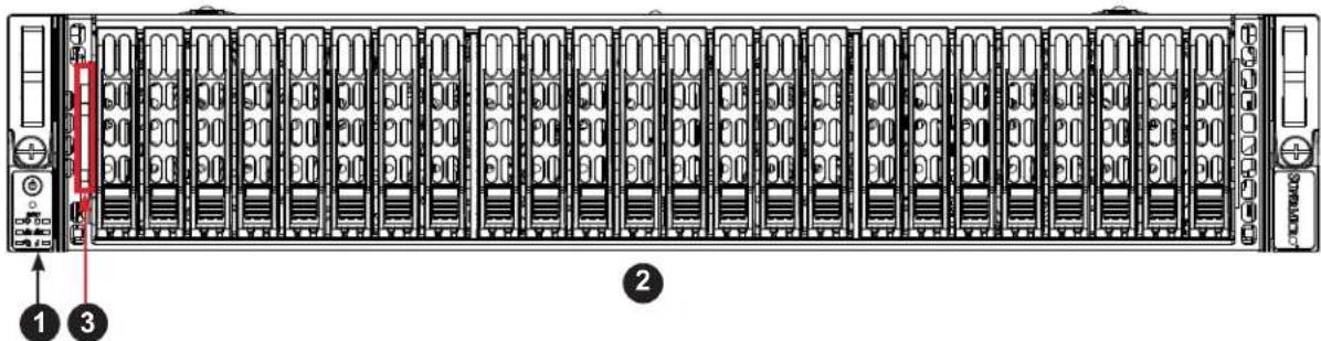
text_image
Diagram of a server rack with labeled ports and numbered components, showing front panel and internal structure.Figure 1-2. Front View
| Chassis Front Features | ||
| Item Features Description | ||
| 1 Control | Panel Power buttons and status indicators | |
| 2 Storage | Drives | Twenty-four 2.5" drive bays; see the "Storage Drive" section in Section 3.4 for details |
| 3 | Service/Asset Tag | Pull-out identifier (with BMC ADMIN default password sticker) |

text_image
BMC Password StickerFigure 1-3. Location of the BMC Password Label
Chassis Rear
The illustration below shows the features included on the rear of the chassis. Power supply modules display status lights.

text_image
Technical diagram of a server rack with numbered components for identificationFigure 1-4. Rear View
| Chassis Rear Features | ||
| Item Features Description | ||
| 1 Power Supply Two redundant power supply modules | ||
| 2 LAN Two RJ45 LAN ports | ||
| 3 USB Two USB 3.0 ports | ||
| 4 IPMI Dedicated LAN port for IPMI | ||
| 5 VGA Video connector | ||
| 6 UID LED Unit ID button and indicator light | ||
| 7 COM port Serial connector |
1.5 Motherboard Layout
Below is a layout of the H11DSU-iN with jumper, connector and LED locations shown. See the table on the following page for descriptions. For detailed descriptions, pinout information and jumper settings, refer to Chapter 4.

flowchart
graph TD
    subgraph Top
        SXB1A --> JIPMB1
        SXB2 --> LEDM1
        NVMePorts --> SXB1B
        JTPM1 --> SGPIO
        SATA8-11 --> GPU PWR3
        JSD1/2 --> CPU2
        LE1 --> CPU2
        JF2 --> CPU2
        JL1 --> CPU2
        FAN8 --> FAN7
        FAN6 --> FAN5
        FAN4 --> FAN3
        FAN2 --> FAN1
    end

    subgraph Bottom
        JBR2 --> VGA
        LED1 --> VBA
        COM1 --> IPMI LAN
        USB0/1 --> USB0/1
        USB0/1 --> USB0/1

        JUIDB2 --> Switch["Switch and UID LED"]
        JSDCARD1 --> Switch
        JPB1/JPG1/JWD1/ --> Switch
        SXB3A --> Switch
        JBT1 --> Switch
        SXB3B --> Switch
        JL2 --> GPU PWR2
        USB3/4 --> GPU PWR2
        SASA12/13 --> GPU PWR2

    end

    SSB1A --> CPU2
    SXB2 --> LEDM1
    LEDM1 --> NVMePorts
    NVMePorts --> SSB1B

    JTPM1 --> SGPIO

    CPU2 --> FAN6
    FAN5 --> FAN4
    FAN3 --> FAN2

    CPU2 --> JPRW2
    CPU2 --> JPRW3
    CPU2 --> USB3

    JPRW2 --> USB3

    JPRW3 --> USB3

    USB3 --> SXTAB-11
    USB3 --> SXTAB-9
    USB3 --> USB3

    CPU2 --> PSU2PSU1
    CPU2 --> PSU1
    CPU2 --> JOPR1
    CPU2 --> SASA0-7
    CPU2 --> JPWR1

    JSPDADT --> SASA0-7
    JSPDADT --> JPWR1

    CPU2 --> GPU_PWR2
    CPU2 --> SASA12/13

    SASA0-7 --> GPU_PWR1

    SASA0-7 --> JPWR1

    SASA0-7 --> JPRW2

    SASA0-7 --> SASA0-7

    SASA0-7 --> JPWR1

    SASA0-7 --> JPRW2

    SASA0-7 --> JPRW3

    SASA0-7 --> JPRW4

    SASA0-7 --> JPRW5

    SASA0-7 --> JPRW6

    SASA0-7 --> JPRW7

    SASA0-7 --> JPRW8

    SASA0-7 --> JPRW9

    SASA0-7 --> JPRW10

    SASA0-7 --> JPRW11

    SASA0-7 --> JPRW12

    SASA0-7 --> JPRW13

    SASA0-7 --> JPRW14

    SASA0-7 --> JPRW15

    SASA0-7 --> JPRW16

    SASA0-7 --> JPRW17

    SASA0-7 --> JPRW18

    SASA0-7 --> JPRW19

    SASA0-7 --> JPRW20

    SASA0-7 --> JPRW21

    SASA0-7 --> JPRW22

    SASA0-7 --> JPRW23

    SASA0-7 --> JPRW24

    SASA0-7 --> JPRW25

    SASA0-7 --> JPRW26

    SASA0-7 --> JPRW27

    SASA0-7 --> JPRW28

    SASA0-7 --> JPRW29

    SASA0-7 --> JPRW30

    SASA0-7 --> JPRW31

    SASA0-7 --> JPRW32

    SASA0-7 --> JPRW33

    SASA0-7 --> JPRW34

    SASA0-7 --> JPRW35

    SASA0-7 --> JPRW36

    SASA0-7 --> JPRW37

    SASA0-7 --> JPRW38

    SASA0-7 --> JPRW39

    SASA0-7 --> JPRW40

    SASA0-7 --> JPRW41

    SASA0-7 --> JPRW42

    SASA0-7 --> JPRW43

    SASA0-7 --> JPRW44

    SASA0-7 --> JPRW45

    SASA0-7 --> JPRW46

    SASA0-7 --> JPRW47

    SASA0-7 --> JPRW48

    SASA0-7 --> JPRW49

    SASA0-7 --> JPRW50

    SASA0-7 --> JPRW51

    SASA0-7 --> JPRW52]

    SASA0-7 --> JPRW53

    SASA0-7 --> JPRW54

    SASA0-7 --> JPRW55

    SASA0-7 --> JPRW56

    SASA0-7 --> JPRW57

    SASA0-7 --> JPRW58

    SASA0-7 --> JPRW59

    SASA0-7 --> JPRW60

    SASA0-7 --> JPRW61

    SASA0-7 --> JPRW62]

    SASA0-7 --> JPRW63

    SASA0-7 --> JPRW64

    SASA0-7 --> JPRW65

    SASA0-7 --> JPRW66

    SASA0-7 --> JPRW67

    SASA0-7 --> JPRW68

    SASA0-7 --> JPRW69

    SASA0-7 --> JPRW70

    SASA0-7 --> JPRW71]

    SASA0-7 --> JPRW72]

    SASA0-7 --> JPRW73]

    SASA0-7 --> JPRW74]

    SASA0-7 --> JPRW75]

    SASA0-7 --> JPRW76]

    SASA0-7 --> JPRW77]

    SASA0-7 --> JPRW78]

    SASA0-7 --> JPRW79]

    SASA0-7 --> JPRW80]

    SASA0-7 --> JPRW81]

    SASA0-7 --> JPRW82]

    SASA0-7 --> JPRW83]

    SASA0-7 --> JPRW84]

    SASA0-7 --> JPRW85]

    SASA0-7 --> JPRW86]

    SASA0-7 --> JPRW87]

    SASA0-7 --> JPRW88]

    SASA0-7 --> JPRW89]

    SASA0-7 --> JPRW90]

    SASA0-7 --> JPRW91]

    SASA0-7 --> JPRW92]

    SASA0-7 --> JPRW93]

    SASA0-7 --> JPRW94]

    SASA0-7 --> JPRW95]

    SASA0-7 --> JPRW96]

    SASA0-7 --> JPRW97]

    SASA0-7 --> JPRW98]

    SASA0-7 --> JPRW99]

    SASA0-7 --> JPRW100]
Figure 1-5. Motherboard Layout
Quick Reference
Jumper Description Default Setting
| J38 CPLD Code Programming NA |
| J39 Debug message through CPU UART0 NA |
| JBR2 Debug Mode for IPMI Use Pins 1-2 (Normal) |
| JBT1 CMOS Clear Open (Normal) |
| JPG1 VGA Enable/Disable Pins 1-2 (Enabled) |
| JVR1 VRM Code Programming Pin1: CLK, Pin2: DAT |
| JWD1 Watch Dog Pins 1-2 (Reset) |
Connector Description
| BT1 | Onboard Battery |
| COM1 | COM Port |
| FAN1~FAN8 | 4-pin System/CPU Fan Headers |
| SATA0~13 | SATA 3.0 Ports |
| SGPIO | Serial Link General Purpose I/O Header |
| JF1 | Front Control Panel Header 1 |
| JF2 | Ultra-IO Riser Card LAN LED Header |
| JIPMB1 | System Management Bus Header |
| JL1 Chassis Intrusion Header | |
| JLAN1 | IPMI Gigabit LAN (RJ45) Port |
| GPU PWR1~3 | 12V 8-pin Power Connector for Riser Card GPU |
| BP PWR1~4 | 12V and 5V 8-pin Power Connector for Backplane |
| JSD1/JSD2 | SATA DOM (Device on Module) power connectors 1/2 |
| JSDCARD1 | SD Card Port (for manufacturer use only) |
| JTPM1 | Trusted Platform Module/Port 80 Connector |
| JUSBA1 | USB 3.0 Type A Header |
| USB3 | Front Panel USB3/4 3.0 ports |
| P1-NVME0/1 | Processor 1 NVMe Ports |
| P2-NVME0/1 | Processor 2 NVMe Ports |
| PSU1 | Motherboard Main Power Supply Connector |
| PSU2 | Motherboard Main Power Supply Connector |
| SXB1A/1B/1C | WIO-L Riser Card Support (CPU1 PCIe 3.0 x16 and CPU2 PCIe 3.0 x16) |
| SXB2 | WIO-R Riser Card Support (CPU2 PCIe 3.0 x16) |
| SXB3A/3B/3C | Ultra I/O Riser Card Support (CPU1 PCIe 3.0 x 24, CPU2 PCIe 3.0 x16) |
| USB0/1 | Back panel Universal Serial Bus (USB) 3.0 Ports |
| VGA | VGA Video Port |
LED Description State: Status
LE1 Power LED Solid Green: Power On
LED1 UID LED Solid Blue: UID Switch On
LEDM1 BMC Heartbeat LED Blinks: Functioning normally
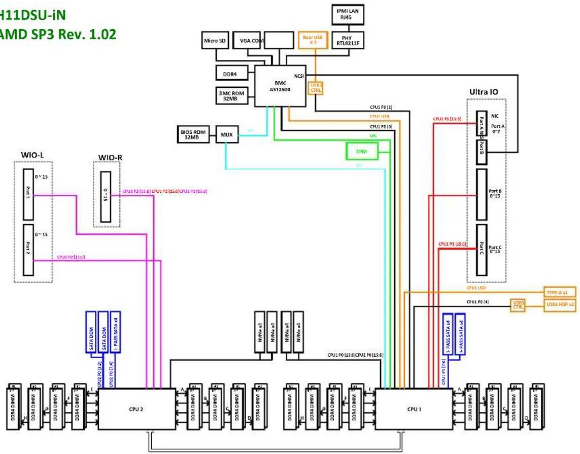
System Block Diagram
H11DSU-iN
AMD SP3 Rev. 1.02
flowchart
graph TD
    A["IPMI LAN RJ4S"] --> B["BMC AST2500"]
    C["Micro SD"] --> B
    D["VGA CDMA"] --> B
    E["DDR4"] --> B
    F["BMC ROM 32MB"] --> B
    G["PHY RTL8211F"] --> B
    H["NCSI"] --> B
    I["BIOS RDM 32MB"] --> J["MUX"]
    K["TPM"] --> J
    L["Ultra IO"] --> M["CPU 1"]
    N["WIO-L"] --> O["CPU 2"]
    P["WIO-R"] --> Q["CPU 2"]
    R["CPU 1"] --> S["CPU 1"]
    T["CPU 1"] --> U["CPU 1"]
    V["CPU 1"] --> W["CPU 1"]
    X["CPU 1"] --> Y["CPU 1"]
    Z["CPU 1"] --> AA["CPU 1"]
    AB["CPU 1"] --> AC["CPU 1"]
    AD["CPU 1"] --> AE["CPU 1"]
    AF["CPU 1"] --> AG["CPU 1"]
    AH["CPU 1"] --> AI["CPU 1"]
    AJ["CPU 1"] --> AK["CPU 1"]
    AL["CPU 1"] --> AM["CPU 1"]
    AN["CPU 1"] --> AO["CPU 1"]
    AP["CPU 1"] --> AQ["CPU 1"]
    AR["CPU 1"] --> AS["CPU 1"]
    AT["CPU 1"] --> AU["CPU 1"]
    AV["CPU 1"] --> AW["CPU 1"]
    AX["CPU 1"] --> AY["CPU 1"]
    AZ["CPU 1"] --> BA["CPU 1"]
    BB["CPU 1"] --> BC["CPU 1"]
    BD["CPU 1"] --> BE["CPU 1"]
    BF["CPU 1"] --> BG["CPU 1"]
    BH["CPU 1"] --> BI["CPU 1"]
    BJ["CPU 1"] --> BK["CPU 1"]
    BL["CPU 1"] --> BM["CPU 1"]
    BN["CPU 1"] --> BO["CPU 1"]
    BP["CPU 1"] --> BQ["CPU 1"]
    BR["CPU 1"] --> BS["CPU 1"]
    BT["CPU 1"] --> BU["CPU 1"]
    BV["CPU 1"] --> BW["CPU 1"]
    BX["CPU 1"] --> BY["CPU 1"]
    BZ["PAS SATA x4"] --> CA["DORA DIMM"]
    BD["PAS SATA x4"] --> CB["DORA DIMM"]
    BE["PAS SATA x4"] --> CC["DORA DIMM"]
    BF["PAS SATA x4"] --> DD["DORA DIMM"]
    BG["PAS SATA x4"] --> DE["DORA DIMM"]
    BH["PAS SATA x4"] --> DF["DORA DIMM"]
    BI["PAS SATA x4"] --> DG["DORA DIMM"]
    BJ["PAS SATA x4"] --> DH["DORA DIMM"]
    BI["PAS SATA x4"] --> DI["DORA DIMM"]
    BJ["PAS SATA x4"] --> DJ["DORA DIMM"]
    BK["PAS SATA x4"] --> DK["DORA DIMM"]
    BL["PAS SATA x4"] --> DL["DORA DIMM"]
    BH["PAS SATA x4"] --> DM["DORA DIMM"]
    BI["PAS SATA x4"] --> DN["DORA DIMM"]
    BJ["PAS SATA x4"] --> DO["DORA DIMM"]
    BK["PAS SATA x4"] --> DP["DORA DIMM"]
    BL["PAS SATA x4"] --> QD["DORA DIMM"]
    BN["PAS SATA x4"] --> RQ["DORA DIMM"]
    BH["PAS SATA x4"] --> SQ["DORA DIMM"]
    BI["PAS SATA x4"] --> TQ["DORA DIMM"]
    BJ["PAS SATA x4"] --> UQ["DORA DIMM"]
    BK["PAS SATA x4"] --> VQ["DORA DIMM"]
    BT["PAS SATA x4"] --> WQ["DORA DIMM"]
    BX["PAS SATA x4"] --> XQ["DORA DIMM"]
    BY["PAS SATA x4"] --> YQ["DORA DIMM"]
    Z["PAS SATA x4"] --> ZQ["DORA DIMM"]
Figure 1-6. System Block Diagram
Note: This is a general block diagram and may not exactly represent the features on your motherboard. See the System Specifications appendix for the actual specifications of your motherboard.
1.6 Where to Get Replacement Components
If you need replacement parts for your system, to ensure the highest level of professional service and technical support, purchase exclusively from our Supermicro Authorized Distributors/System Integrators/Resellers. A list can be found at: http://www.supermicro.com. Click the "Where to Buy" link.
1.7 Returning Merchandise for Service
A receipt or copy of your invoice marked with the date of purchase is required before any warranty service will be rendered. You can obtain service by calling your vendor for a Returned Merchandise Authorization (RMA) number. When returning to the manufacturer, the RMA number should be prominently displayed on the outside of the shipping carton, and mailed prepaid or hand-carried. Shipping and handling charges will be applied for all orders that must be mailed when service is complete.
For faster service, RMA authorizations may be requested online (http://www.supermicro.com/support/rma/).
Whenever possible, repack the chassis in the original Supermicro carton, using the original packaging material. If these are no longer available, be sure to pack the chassis securely, using packaging material to surround the chassis so that it does not shift within the carton and become damaged during shipping.
This warranty only covers normal consumer use and does not cover damages incurred in shipping or from failure due to the alteration, misuse, abuse or improper maintenance of products.
During the warranty period, contact your distributor first for any product problems.
Chapter 2
Server Installation
2.1 Overview
This chapter provides advice and instructions for mounting your system in a server rack. If your system is not already fully integrated with processors, system memory etc., refer to Chapter 4 for details on installing those specific components.
Caution: Electrostatic Discharge (ESD) can damage electronic components. To prevent such damage to PCBs (printed circuit boards), it is important to use a grounded wrist strap, handle all PCBs by their edges and keep them in anti-static bags when not in use.
2.2 Preparing for Setup
The box in which the system was shipped should include the rackmount hardware needed to install it into the rack. Please read this section in its entirety before you begin the installation.
Choosing a Setup Location
- The system should be situated in a clean, dust-free area that is well ventilated. Avoid areas where heat, electrical noise and electromagnetic fields are generated.
- Leave enough clearance in front of the rack so that you can open the front door completely (\~25 inches) and approximately 30 inches of clearance in the back of the rack to allow sufficient space for airflow and access when servicing.
- This product should be installed only in a Restricted Access Location (dedicated equipment rooms, service closets, etc.).
- This product is not suitable for use with visual display workplace devices according to §2 of the German Ordinance for Work with Visual Display Units.
Rack Precautions
- Ensure that the leveling jacks on the bottom of the rack are extended to the floor so that the full weight of the rack rests on them.
- In single rack installations, stabilizers should be attached to the rack. In multiple rack installations, the racks should be coupled together.
- Always make sure the rack is stable before extending a server or other component from the rack.
- You should extend only one server or component at a time - extending two or more simultaneously may cause the rack to become unstable.
Server Precautions
- Review the electrical and general safety precautions in Appendix A.
- Determine the placement of each component in the rack before you install the rails.
- Install the heaviest server components at the bottom of the rack first and then work your way up.
- Use a regulating uninterruptible power supply (UPS) to protect the server from power surges and voltage spikes and to keep your system operating in case of a power failure.
- Allow any drives and power supply modules to cool before touching them.
- When not servicing, always keep the front door of the rack and all covers/panels on the servers closed to maintain proper cooling.
Rack Mounting Considerations
Ambient Operating Temperature
If installed in a closed or multi-unit rack assembly, the ambient operating temperature of the rack environment may be greater than the room's ambient temperature. Therefore, consideration should be given to installing the equipment in an environment compatible with the manufacturer's maximum rated ambient temperature (TMRA).
Airflow
Equipment should be mounted into a rack so that the amount of airflow required for safe operation is not compromised.
Mechanical Loading
Equipment should be mounted into a rack so that a hazardous condition does not arise due to uneven mechanical loading.
Circuit Overloading
Consideration should be given to the connection of the equipment to the power supply circuitry and the effect that any possible overloading of circuits might have on overcurrent protection and power supply wiring. Appropriate consideration of equipment nameplate ratings should be used when addressing this concern.
Reliable Ground
A reliable ground must be maintained at all times. To ensure this, the rack itself should be grounded. Particular attention should be given to power supply connections other than the direct connections to the branch circuit (i.e. the use of power strips, etc.).

To prevent bodily injury when mounting or servicing this unit in a rack, you must take special precautions to ensure that the system remains stable. The following guidelines are provided to ensure your safety:
- This unit should be mounted at the bottom of the rack if it is the only unit in the rack.
- When mounting this unit in a partially filled rack, load the rack from the bottom to the top with the heaviest component at the bottom of the rack.
- If the rack is provided with stabilizing devices, install the stabilizers before mounting or servicing the unit in the rack.
- Slide rail mounted equipment is not to be used as a shelf or a work space.
2.3 Installing the Rails
This section provides information on installing the chassis into a rack unit with the rails provided. There are a variety of rack units on the market, which may mean that the assembly procedure will differ slightly from the instructions provided. You should also refer to the installation instructions that came with the rack unit you are using. Note: This rail will fit a rack between 26.8" and 36.4" deep.
Overview of the Rack Rails
The package includes two rail assemblies. Each is specifically designed for the left or right side of the chassis, and so marked. Each rail consists of two sections: a front section which secures to the front post of the rack and a rear section which adjusts in length and secures to the rear post of the rack.
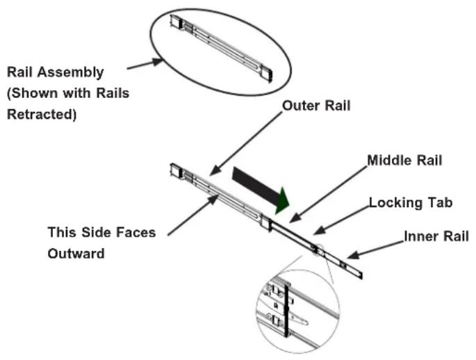
text_image
Rail Assembly (Shown with Rails Retracted) Outer Rail Middle Rail Locking Tab Inner Rail This Side Faces OutwardFigure 2-1. Identifying the Outer Rail, Middle Rail and Inner Rail (Left Rail Assembly Shown)
Note: Both front chassis rails and the rack rails have a locking tab, which serves two functions. First, it locks the server into place when installed and pushed fully into the rack (its normal operating position. In addition, these tabs lock the server in place when fully extended from the rack. This prevents the server from coming completely out of the rack when pulled out for servicing.
Releasing the Inner Rail
Each inner rail has a locking latch. This latch prevents the server from coming completely out of the rack when when the chassis is pulled out for servicing.
To mount the rail onto the chassis, first release the inner rail from the outer rails.
- Pull the inner rail out of the outer rail until it is fully extended as illustrated below.
- Press the locking tab down to release the inner rail.
- Pull the inner rail all the way out.

text_image
Diagram showing three steps of a mechanical assembly with labeled components and directional arrowsFigure 2-2. Extending and Releasing the Inner Rail
Installing the Inner Rails
Begin the rack mounting procedure by installing the inner rails to the chassis.
- Identify the left and right inner rails. They are labeled.
- Place the inner rail firmly against the side of the chassis, aligning the hooks on the side of the chassis with the holes in the inner rail.
- Slide the inner rail forward toward the front of the chassis and under the hooks until the quick release bracket snaps into place, securing the rail to the chassis.
- Optionally, you can further secure the inner rail to the chassis with a screw.

text_image
Inner Rails 2 3Figure 2-3. Installing the Rails

Warning: Do not pick up the server with the front handles. They are designed to pull the system from a rack only.
Installing the Outer Rails onto the Rack
- Press upward on the locking tab at the rear end of the middle rail.
- Push the middle rail back into the outer rail.
- Hang the hooks on the front of the outer rail onto the square holes on the front of the rack. If desired, use screws to secure the outer rails to the rack.
- Pull out the rear of the outer rail, adjusting the length until it just fits within the posts of the rack.
- Hang the hooks of the rear section of the outer rail onto the square holes on the rear of the rack. Take care that the proper holes are used so the rails are level. If desired, use screws to secure the rear of the outer rail to the rear of the rack.

text_image
Technical diagram illustrating four stages of a mechanical assembly or mounting mechanism with labeled components and directional arrows.Figure 2-4. Installing the Outer Rails to the Rack
Note: Figure is for illustrative purposes only. Always install servers at the bottom of a rack first.

Stability hazard. The rack stabilizing mechanism must be in place, or the rack must be bolted to the floor before you slide the unit out for servicing. Failure to stabilize the rack can cause the rack to tip over.
2.4 Installing the Server into a Rack
Once rails are attached to the chassis and the rack, you can install the server.
Caution: Heavy! Use two or more people, or a lift to install the server.
- Pull the middle rail out of the front of the outer rail and make sure that the ball bearing shuttle is locked at the front of the middle rail.
- Align the rear of the chassis rails with the middle rails and then push evenly on both sides of the chassis until it clicks into the fully extended position.
- Depress the locking tabs on both sides of the chassis and push the it fully into the rack. The locking tabs should "click".
- Optional screws may be used to hold the front of the chassis to the rack.

text_image
Ball-Bearing ShuttleFigure 2-5. Installing the Server into the Rack
Note: Keep the ball bearing shuttle locked at the front of the middle rail during installation.
Note: Figure is for illustrative purposes only. Always install servers to the bottom of a rack first.
Removing the Chassis from the Rack
Caution! It is dangerous for a single person to off-load the heavy chassis from the rack without assistance. Be sure to have sufficient assistance supporting the chassis when removing it from the rack. Use a lift.
-
Pull the chassis forward out the front of the rack until it stops.
-
Press the release latches on each of the inner rails downward simultaneously and continue to pull the chassis forward and out of the rack.

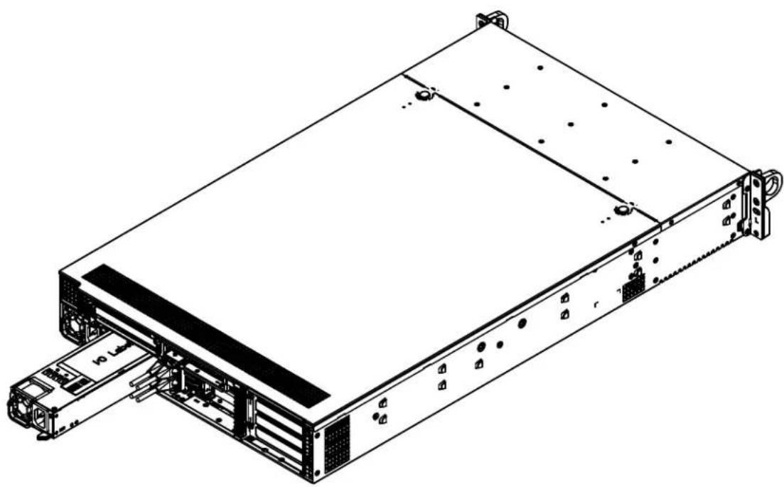
natural_image
Technical line drawing of a server rack unit with labeled component (no text or symbols beyond part number)Figure 2-6. Removing the Chassis From the Rack
Chapter 3
Maintenance and Component Installation
This chapter provides instructions on installing and replacing main system components. To prevent compatibility issues, only use components that match the specifications and/or part numbers given.
Installation or replacement of most components require that power first be removed from the system. Please follow the procedures given in each section.
3.1 Removing Power
Use the following procedure to ensure that power has been removed from the system. This step is necessary when removing or installing non hot-swap components or when replacing a non-redundant power supply.
- Use the operating system to power down the system.
- After the system has completely shut-down, disconnect the AC power cord(s) from the power strip or outlet. (If your system has more than one power supply, remove the AC power cords from all power supply modules.)
- Disconnect the power cord(s) from the power supply module(s).
3.2 Accessing the System
The SC219U chassis features a removable top cover that allows access to components. Check that all ventilation openings in the chassis are clear and unobstructed.
Removing the Top Cover
- Remove the two screws on the side of the chassis that secures the cover to the chassis
- Press the two release buttons and slide the cover toward the rear.
- Lift the top cover up.
Caution: Except for short periods of time, do not operate the server without the cover in place. The chassis cover must be in place to allow for proper airflow and to prevent overheating.
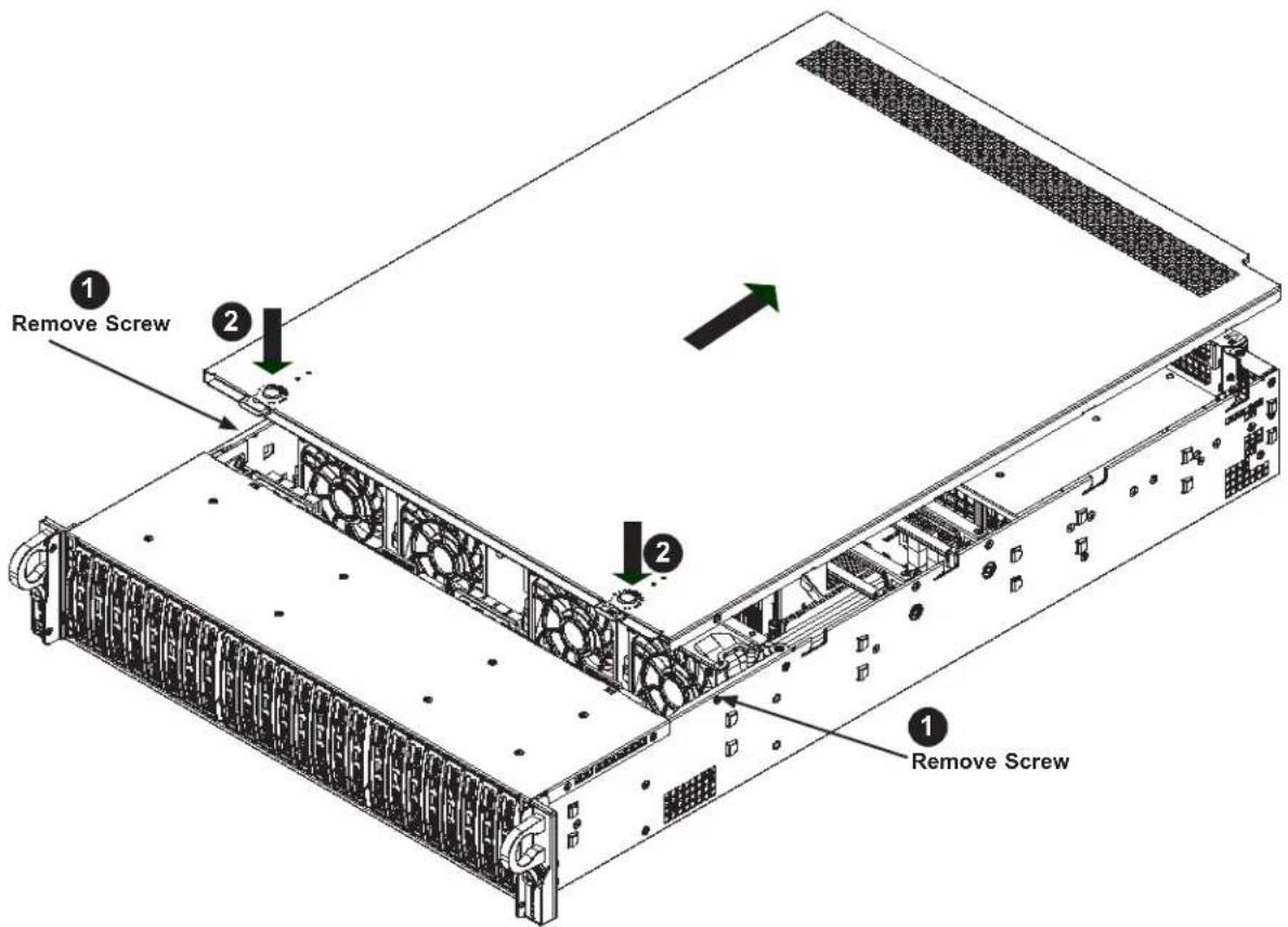
text_image
1 Remove Screw 2 1 2 1 Remove ScrewFigure 3-1. Removing the Chassis Cover
3.3 Motherboard Components
Processor and Heatsink Installation
Follow the procedures in this section to install a processor (CPU) and heatsink to the motherboard.
Notes:
- Use ESD protection.
• Power down the system as described in Section 3.1. - The motherboard should be installed into the chassis first and the processor should be installed into the CPU socket before you install a CPU heatsink.
- If you bought a CPU separately, make sure to use a certified multi-directional heatsink only.
- When receiving a motherboard without a processor pre-installed, make sure that the plastic CPU socket cap is in place and none of the socket pins are bent; otherwise, contact your retailer immediately.
- Refer to the Supermicro website for updates on CPU support. All graphics in this manual are for illustration only. Your components may look different.
Installing the Processor and Heatsink
Begin by removing power from the system as described in Section 3.1.
text_image
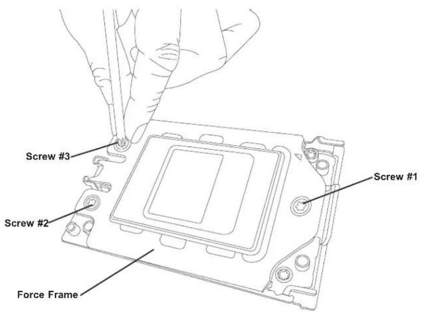
Screw #3 Screw #2 Force Frame Screw #1Figure 3-2. Removing the Processor Force Frame
- Use a Torx T20 driver to loosen the screws holding down Force Frame in the sequence of 3-2-1. The screws are numbered on the Force Frame next to each screw hole.
natural_image
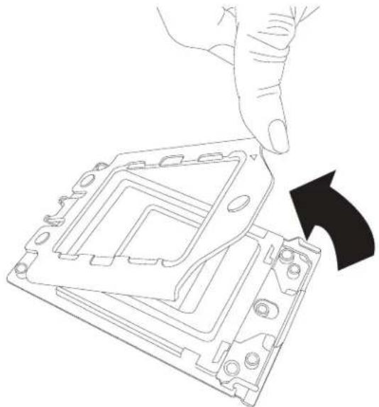
Line drawing of a hand pressing down on a computer processor casing with an arrow indicating the process (no text or symbols present)Figure 3-3. Raising the Force Frame
Tighten to 16.1 kgf-cm (14 lbf-in) of torque.
- The spring-loaded Force Frame will raise up after the last screw (#1) is removed. Gently allow it to lift up to its stopping position.
text_image
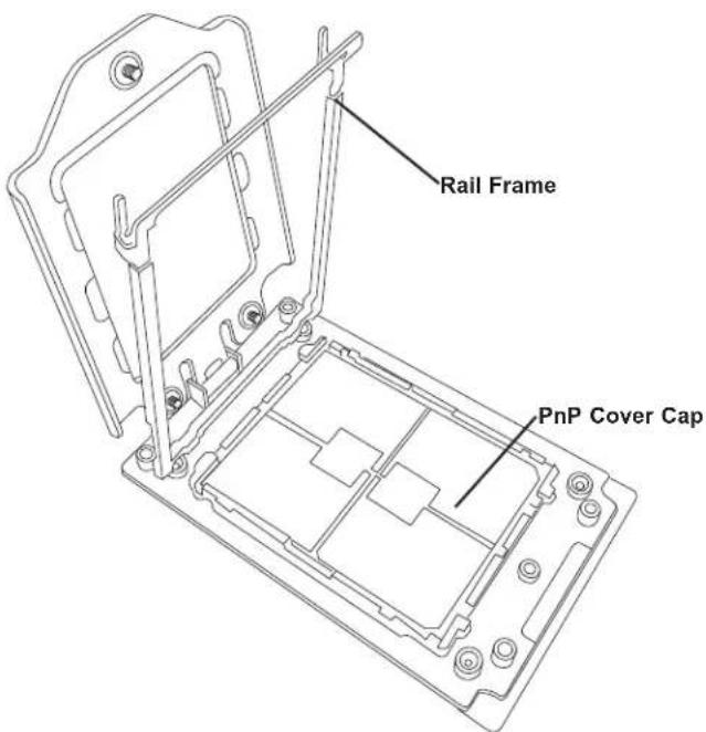
Rail Frame PnP Cover CapFigure 3-4. Lifting the Rail Frame
- Lift the Rail Frame up by gripping the lift tabs near the front end of the rail frame. While keeping a secure grip of the Rail Frame, lift it to a position so you can do the next step

text_image
External Cap PnP Cover CapFigure 3-5. Removing the External Cap
of removing the External Cap.
Note: The Rail Frame is spring loaded, so keep a secure grip on it as you lift it so it does not snap up.
- Remove the External Cap from the Rail Frame by pulling it upwards through the rail guides on the Rail Frame.

text_image
Carrier Frame/ CPU PackageFigure 3-6. Inserting the Carrier Frame/CPU Package
- The CPU Package is shipped from the factory with the blue Carrier Frame pre-assembled. Grip the handle of the Carrier Frame/CPU Package assembly from its shipping tray, and while gripping the handle, align the flanges of the Carrier Frame onto the rails of the Rail Frame so its pins will be at the bottom when the Rail Frame is lowered later.
- Slide the Carrier Frame/CPU Package downwards to the bottom of the Rail Frame. Ensure the flanges are secure on the rails as you lower it downwards.
Note: You can only install the CPU inside the socket in one direction with the handle at the top. Make sure that it is properly inserted into the CPU socket before closing the Rail Frame plate. If it doesn't close properly, do not force it as it may damage your CPU. Instead, open the Rail Frame plate again, and double-check that the CPU is aligned properly.
- Lift up the Rail Frame till it securely rests in upright position. Then remove the PnP Cover Cap from the CPU socket below. Grip the two lift tabs marked "Remove" at the middle of the cap and pull vertically upwards to remove the PnP Cover Cap.
natural_image
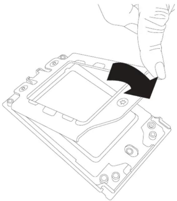
Line drawing of a hand pressing down on a computer processor's internal components (no text or symbols)Figure 3-7. Lowering the Force Frame

natural_image
Line drawing of hands installing or adjusting a component on a circuit board (no text or symbols)Figure 3-8. Securing the Force Frame
Caution: The exposed socket contacts are extremely vulnerable and can be damaged easily. Do not touch or drop objects onto the contacts and be careful removing the PnP Cover Cap and when placing the Rail Frame over the socket.

natural_image
Technical line drawing of a mechanical component with mounting holes and a central square feature (no text or symbols)Figure 3-9. The Force Frame Secured
- Gently lower the Rail Frame down onto the socket until the latches on the Rail Frame engage with the Socket housing. and it rests in place. Do not force it into place!
natural_image
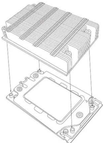
Technical line drawing of a heat exchanger or cooling unit with internal components and mounting holes (no text or symbols)Figure 3-10. Mounting the Heatsink
- Gently lower the Force Frame down onto the Rail Frame and hold it in place until it is seated in the Socket housing. Note that the Force Frame is spring loaded and has to be held in place before it is secured.
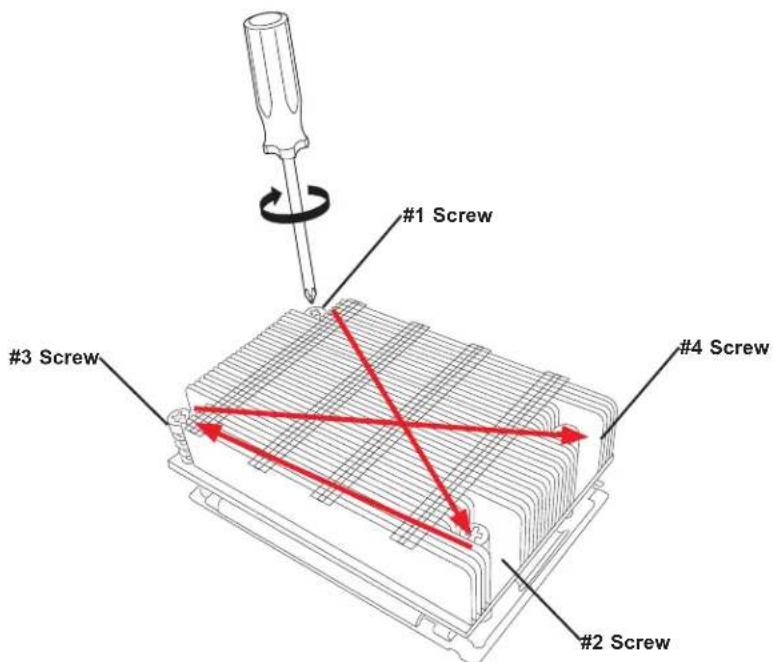
text_image
#1 Screw #3 Screw #4 Screw #2 ScrewFigure 3-11. Securing the Heatsink
The processor and heatsink installation is complete. Repeat this procedure for any remaining CPU sockets on the motherboard.
- Replace the screws in the order 1-2-3, tightening to 16.1 kgf-cm (14 lbf-in) of torque. The Force Frame secures both the Rail Frame and CPU Package.
Caution: Tightening must be executed in proper 1-2-3 sequence to avoid causing catastrophic damage to the socket or CPU Package.
-
Lower the heatsink down till it rests securely on CPU Package over the four screw holes on the socket frame.
-
Using a diagonal pattern and a Torx T20 driver, tighten the four heatsink screws evenly to 16.1 kgf-cm (14.0 lbf-in) of torque.
Removing a Heatsink
We do not recommend removing the heatsink. If necessary, please follow the instructions below to prevent damage to the CPU or the CPU socket.
Note: Wait for the heatsink to cool down before removing it.
-
Unscrew and remove the heatsink screws from the motherboard in the sequence as show in the figure above.
-
Hold and gently pivot the heatsink back and forth to loosen it from the CPU. (Do not use excessive force when dislodging the heatsink!)
-
Once the heatsink is loose, remove it from the CPU.
-
Clean the surface of the CPU and the heatsink to get rid of the old thermal grease. Reapply the proper amount of thermal grease to the surface before you re-install the heatsink.
Memory Installation
Memory Support
The H11DSU-iN supports up to 4TB of ECC DDR4 2666 MHz speed or 8TB of ECC DDR4 3200 MHz speed (board reversion 2.x required), RDIMM/LRDIMM/3DS/NVDIMM memory in 32 slots. Refer to the table below for additional memory information.
Check the Supermicro website for possible updates to memory support.
Caution: Exercise extreme caution when installing or removing memory modules to prevent any possible damage to the DIMMs or slots.
| Processors and their Corresponding Memory Modules | ||||||||||||||||
| CPU# | Channel 1 | Channel 2 | Channel 3 | Channel 4 | Channel 5 | Channel 6 | Channel 7 | Channel 8 | ||||||||
| 8 DIMMS | ||||||||||||||||
| CPU1 | A2 B2 | C2 D2 | E2 F2 | G2 H2 | ||||||||||||
| 16 DIMMS | ||||||||||||||||
| CPU1 | A1 A2 | B1 B2 | C1 C2 | D1 D2 | E1 E2 F | F1 F2 G | G1 G2 H1 | H2 | ||||||||
| 16 DIMMS | ||||||||||||||||
| CPU1 | A2 B2 | C2 D2 | E2 F2 | G2 H2 | ||||||||||||
| CPU2 | A2 B2 | C2 D2 | E2 F2 | G2 H2 | ||||||||||||
| 32 DIMMS | ||||||||||||||||
| CPU1 | A1 A2 | B1 B2 | C1 C2 | D1 D2 | E1 E2 F | F1 F2 G | G1 G2 H1 | H2 | ||||||||
| CPU2 | A1 A2 | B1 B2 | C1 C2 | D1 D2 | E1 E2 F | F1 F2 G | G1 G2 H1 | H2 | ||||||||
(More population information on the following page)
| Populating RDIMM/RDIMM 3DS/LRDIMM/LRDIMM 3DS DDR4 Memory Modules with 7001 Processor | ||||
| Type | DIMM Population | Maximum DIMM Capacity (GB) | Maximum Frequency (MHz) | |
| DIMM1 DIMM2 1 Channel 8 Channel | ||||
| RDIMM | 1R 16GB 128GB 2666 | |||
| 1R 1R 32GB 256GB 2133 | ||||
| 2R 64GB 512GB 2400 | ||||
| 1R 2R 48GB 384GB 2133 | ||||
| 2R 2R 128GB 1TB 2133 | ||||
| LRDIMM | 4R 64GB 512GB 2666 | |||
| 4R 4R 128GB 1TB 2133 | ||||
| 8R 128GB 1TB 2666 | ||||
| 4R 8R 192GB 1.5TB 2133 | ||||
| 8R 8R 256GB 2TB 2133 | ||||
| LRDIMM 3DS | 2R2H 64GB 512GB 2400 | |||
| 2R2H 2R2H 128GB 1TB 1866 | ||||
| 2R4H 128GB 1TB 2400 | ||||
| 2R2H 2R4H 192GB 1.5TB 1866 | ||||
| 2R4H 2R4H 256GB 2TB 1866 | ||||
| Populating RDIMM/RDIMM 3DS/LRDIMM/LRDIMM 3DS DDR4 Memory Modules with 7002 Processor | ||||
| Type | DIMM Population | Maximum DIMM Capacity (GB) | Maximum Frequency (MHz) | |
| DIMM1 DIMM2 1 Channel 8 Channel | ||||
| RDIMM | 1R 32GB 256GB 3200 | |||
| 1R 1R 64GB 512GB 2933 | ||||
| 2R or 2DR 64GB 512GB 3200 | ||||
| 1R 2R or 2DR 96GB 76GB 2933 | ||||
| 2R or 2DR | 2R or 2DR | 128GB 1TB 2933 | ||
| LRDIMM | 2S2R 128GB 1TB 3200 | |||
| 2S4R 256GB 2TB 3200 | ||||
| 2S2R 2S2R 256GB 2TB 2933 | ||||
| 2S2R 2S4R 384GB 3TB 2933 | ||||
| 2S2R 2S4R 512GB 4TB 2933 | ||||
| LRDIMM 3DS | 2S2R 128GB 1TB 2933 | |||
| 2S2R 2S2R 256GB 2TB 2666 | ||||
| 2S4R 256GB 2TB 2933 | ||||
| 2S2R 2S4R 384GB 3TB 2666 | ||||
| 2S4R 2S4R 512GB 4TB 2666 | ||||
DIMM Module Population Sequence
When installing memory modules, the DIMM slots should be populated in the following order: DIMMA2, DIMMB2, DIMMC2, DIMMD2, DIMME2, DIMMF2, DIMMG2, DIMMH2, then DIMMA1, DIMMB1, DIMMC1, DIMMD1, DIMME1, DIMMF1, DIMMG1, DIMMH1.
• The blue slots must be populated first.
• Always use DDR4 DIMM modules of the same type, size and speed.
- Mixed DIMM speeds can be installed. However, all DIMMs will run at the speed of the slowest DIMM.
- The motherboard supports an odd number of modules (1, 3, etc.). However, to achieve the best memory performance, a balanced memory population is recommended.

text_image
QALTONO LENVACON P2-DIMMA1 P2-DIMMA2 P2-DIMMA1 P2-DIMMA2 P2-DIMMD1 P2-DIMMD2 P2-DIMME1 P2-DIMMH1 P2-DIMMH2 P2-DIMMH1 P2-DIMMH2 P2-DIMMH1 P2-DIMMH2 P2-DIMMH1 P2-DIMMH2 P2-DIMMH1 P2-DIMMH2 P2-DIMMH1 P2-DIMMH2 P2-DIMMH1 P2-DIMMH2 P2-DIMMH1 P2-DIMMH2 LNNNAMM0000000000000000000000000000000000000000000000000000000000000000000000000000000000000000000000000000 P1-DIMMD1 P1-DIMMD2 P1-DIMMD1 P1-DIMMD2 P1-DIMMD1 P1-DIMMD2 P1-DIMMD1 P1-DIMMD2 P1-DIMMD1 P1-DIMMD2 P1-DIMMD1 P1-DIMMD2 P1-DIMMD1 P1-DIMMD2 P1-DIMMD1 P1-DIMMD2 LNNNAMM000000000000000000000000000000000000000000000000Figure 3-12. DIMM Numbering
Caution: In dual-CPU configurations, memory must be installed in the DIMM slots associated with the installed CPUs.
Installing Memory
ESD Precautions
Electrostatic Discharge (ESD) can damage electronic components including memory modules. To avoid damaging DIMM modules, it is important to handle them carefully. The following measures are generally sufficient.
- Use a grounded wrist strap designed to prevent static discharge.
- Handle the memory module by its edges only.
- Put the memory modules into the antistatic bags when not in use.
Installing Memory
Begin by removing power from the system as described in Section 3.1, and remove the node from the chassis. Follow the memory population sequence in the table above.
- Push the release tabs outwards on both ends of the DIMM slot to unlock it.

text_image
Notches Release Tabs- Align the key of the DIMM with the receptive point on the memory slot and with your thumbs on both ends of the module, press it straight down into the slot until the module snaps into place.
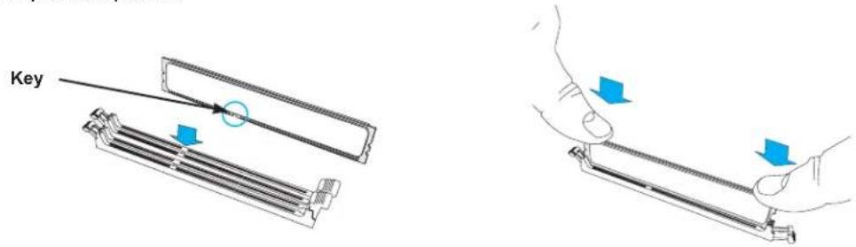
text_image
Key- Press the release tabs to the locked position to secure the DIMM module into the slot.
Caution: Exercise extreme caution when installing or removing memory modules to prevent damage to the DIMMs or slots.
Removing Memory
To remove a DIMM, unlock the release tabs then pull the DIMM from the memory slot.
Motherboard Battery
The motherboard uses non-volatile memory to retain system information when system power is removed. This memory is powered by a lithium battery residing on the motherboard.
Replacing the Battery
Begin by removing power from the system as described in section 3.1.
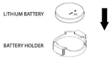
- Push aside the small clamp that covers the edge of the battery. When the battery is released, lift it out of the holder.
- To insert a new battery, slide one edge under the lip of the holder with the positive (+) side facing up. Then push the other side down until the clamp snaps over it.
Note: Handle used batteries carefully. Do not damage the battery in any way; a damaged battery may release hazardous materials into the environment. Do not discard a used battery in the garbage or a public landfill. Please comply with the regulations set up by your local hazardous waste management agency to dispose of your used battery properly.
text_image
LITHIUM BATTERY BATTERY HOLDERFigure 3-13. Installing the Onboard Battery
Warning: There is a danger of explosion if the onboard battery is installed upside down (which reverses its polarities). This battery must be replaced only with the same or an equivalent type recommended by the manufacturer (CR2032).
3.4 Chassis Components
This section provides instructions on installing and replacing system components. To assure compatibility, only use components that match the specifications or part numbers given.
Installation or replacement of most components require that power first be removed from the system.
Storage Drives
The SC219U supports twenty-four 2.5" hot-swap NVMe storage drives in toolless drive carriers that simplify their removal from the chassis. These carriers also help promote proper airflow.
Note: Enterprise level hard disk drives are recommended for use in Supermicro chassis and servers. For information on recommended HDDs, visit the Supermicro website at, https://origin.supermicro.com/Aplus/system/2U/2123/AS-2123US-TN24R25M.cfm
Drive Carrier Indicators
Each drive carrier has two LED indicators: an activity indicator and a status indicator. In RAID configurations, the status indicator lights to indicate the status of the drive. In non-RAID configurations, the status indicator remains off. See the table below for details.
| Drive Carrier LED Indicators | |||
| Color Blinking Pattern Behavior for Device | |||
| Activity LED | Blue Solid On SAS/NVMe drive installed | ||
| Blue Blinking I/O activity | |||
| Status LED | Red Solid On Failure of drive with RSTe support | ||
| Red Blinking at 1 Hz Rebuild drive with RSTe support | |||
| Red Blinking with two blinks and one stop at 1 Hz | Hot spare for drive with RSTe support | ||
| Red On for five seconds, then off | Power on for drive with RSTe support | ||
| Red Blinking at 4 Hz Identify drive with RSTe support | |||
| Green Solid On Safe to remove NVMe device | |||
| Amber Blinking at 1 Hz Attention state—do not remove NVMe device | |||
Removing a Hot-Swap Drive Carrier from the Chassis
- Press the release button on the drive carrier, which will extend the drive carrier handle.
- Use the drive carrier handle to pull the drive out of the chassis.
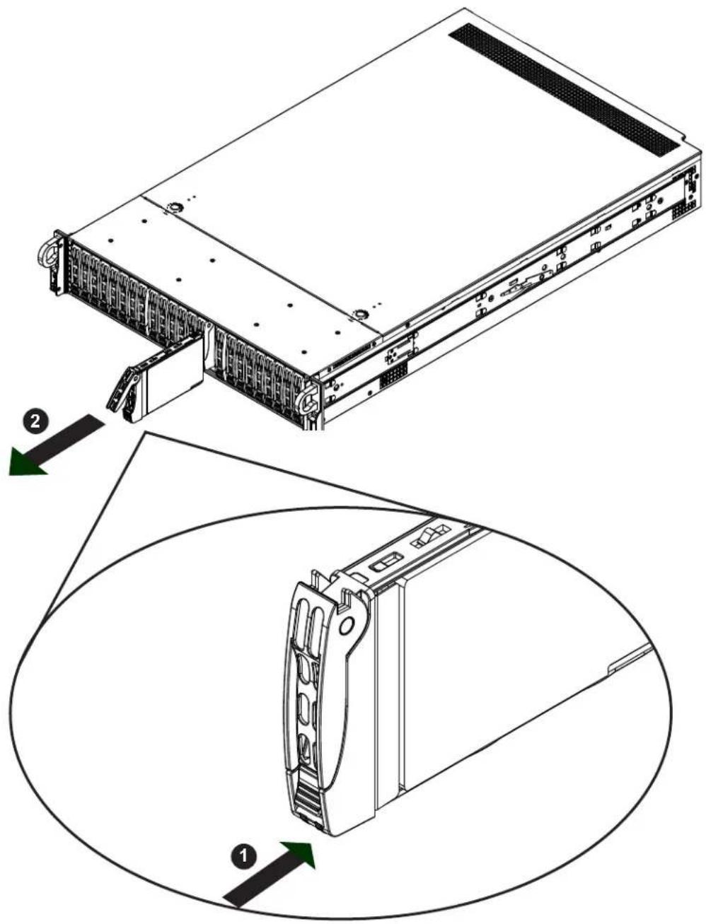
text_image
Technical diagram of a server rack with labeled components and directional arrows indicating assembly steps.Figure 3-14. Removing a Drive Carrier
Note: Except for short periods of time while swapping hard drives, do not operate the server without the carriers in the drive bays.
Installing a Drive
- Remove the dummy drive, which comes pre-installed in the drive carrier, by removing the screws securing the dummy drive to the carrier. These screws are not used to mount the actual hard drive.
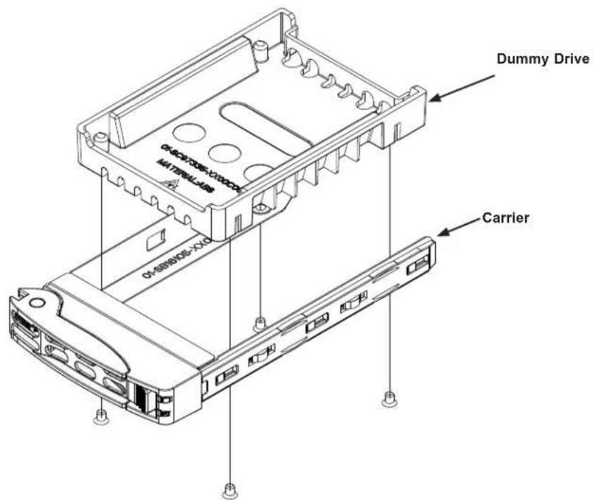
text_image
Dummy Drive OKAOV0005-V100004 MATHWELL-ABS 01-889805-XX0 CarrierFigure 3-15. Removing the Dummy Drive from a Carrier
- Insert a drive into the carrier with the PCB side facing down and the connector end toward the rear of the carrier. Align the drive in the carrier so that the screw holes line up. Note that there are holes in the carrier marked "SATA" to aid in correct installation.
- Secure the drive to the carrier with four M3 screws, included in the chassis accessory box.
- Insert the drive carrier with the disk drive into its bay, keeping the carrier oriented so that the release button is on the right side. When the carrier reaches the rear of the bay, the release handle retracts.
- Push the handle in until it clicks into its locked position.
Cabling for NVMe
Use OCuLink cables to connect the backplane (BPN-NVME3-216N-S4) to the NVMe add-on cards (AOC-SLG3-2E4R and AOC-SLG3-4E4R) and the motherboard. The proper ports must be connected so that all NVMe drives will be detected.
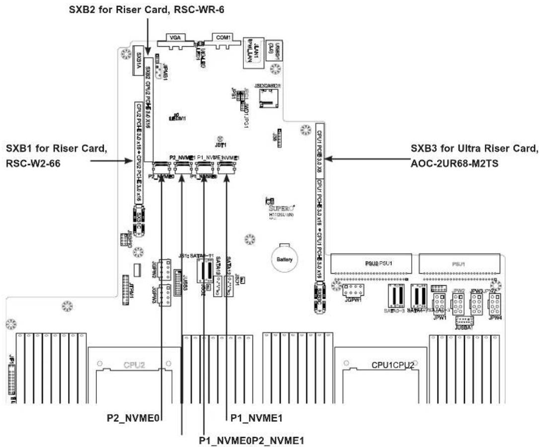
flowchart
graph TD
    A["SXB2 for Riser Card, RSC-WR-6"] --> B["SXB1 for Riser Card, RSC-W2-66"]
    B --> C["CPU1CPU2"]
    C --> D["P1_NVME0P2_NVME1"]
    C --> E["P1_NVME1"]
    C --> F["P2_NVME0"]
    C --> G["P2_NVME1"]
    C --> H["CPU1PCB 3.0 X5"]
    C --> I["CPU1PCB 3.0 X18 + CPU1PCB 3.0 X19"]
    C --> J["PSU2PSU1"]
    C --> K["PSU1"]
    C --> L["PSU3PSU2"]
    C --> M["PSU4PSU3"]
    C --> N["PSU5PSU4"]
    C --> O["PSU6PSU5"]
    C --> P["PSU7PSU6"]
    C --> Q["PSU8PSU7"]
    C --> R["PSU9PSU8"]
    C --> S["PSU10PSU9"]
    C --> T["PSU11PSU10"]
    C --> U["PSU12PSU11"]
    C --> V["PSU13PSU12"]
    C --> W["PSU14PSU13"]
    C --> X["PSU15PSU14"]
    C --> Y["PSU16PSU15"]
    C --> Z["PSU17PSU16"]
    C --> AA["PSU18PSU17"]
    C --> AB["PSU19PSU18"]
    C --> AC["PSU20PSU19"]
    C --> AD["PSU21PSU20"]
    C --> AE["PSU22PSU21"]
    C --> AF["PSU23PSU22"]
    C --> AG["PSU24PSU23"]
Figure 3-16. Motherboard Connections for NMVe
Positions of Add-on Cards
- Plug AOC-SLG3-4E4R into the lower slot ^6 of RSC-W2-66 in SXB1.
- Plug AOC-SLG3-4E4R into the upper slot ^5 of RSC-W2-66 in SXB1.
- Plug AOC-SLG3-4E4R into the slot ④ of RSC-WR-6 in SXB2.
- Plug AOC-SLG3-2E4R into the lower-left slot ^3 of Ultra Riser card AOC-2UR68-M2TS in SXB3.
- Plug AOC-SLG3-4E4R into the upper-left slot ^2 of Ultra Riser card AOC-2UR68-M2TS in SXB3.
- Plug AOC-SLG3-2E4R into the right slot of Ultra Riser card AOC-2UR68-M2TS in SXB3.
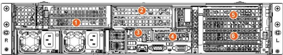
text_image
Diagram of an internal server rack with numbered components and labeled portsFigure 3-17. Add-on Card Positions (inside chassis)
Jumper Setting on One Add-on Card
The AOC-SLG3-4E4R add-on card in slot ④ of RSC-WR-6 requires a jumper change to these settings.
- JP2 – Pins 1 and 2
- JP3 – Pins 1 and 2
- JP4 – Pins 2 and 3
- JP1 – No jumper
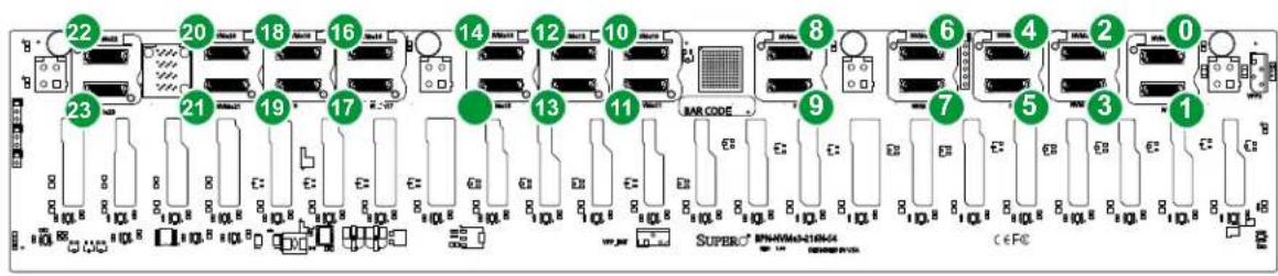
text_image
22 20 18 16 14 12 10 8 6 4 2 0 23 21 19 17 13 11 MAR CODE 9 7 5 3 1 SUPER BPHMMA-216N4 CE FCFigure 3-18. Backplane BPN-NVME3-216N-S4 Showing NVMe Drive Numbers (Also labeled on the backplane)
| NVMe Cabling | ||||
| From CPU Routing Cable Backplane Port | ||||
| Motherboard connectors | P1_NVME0 CPU0 P0 | CBL-SAST-0819 NVMe #0 | ||
| P1_NVME1 CPU0 P0 | CBL-SAST-0819 NVMe #1 | |||
| P2_NVME0 CPU1 P0 | CBL-SAST-0818 NVMe #10 | |||
| P2_NVME1 CPU1 P0 | CBL-SAST-0818 NVMe #11 | |||
| In RSC-W2-66 upper slot 5 AOC-SLG3-4E4R | Port #0 CPU1 P2 CBL | -SAST-0841 NVMe #16 | ||
| Port #1 CPU1 P2 CBL | -SAST-0841 NVMe #17 | |||
| Port #2 CPU1 P2 CBL | -SAST-0841 NVMe #18 | |||
| Port #3 CPU1 P2 CBL | -SAST-0841 NVMe #19 | |||
| In RSC-W2-66 lower slot 6 AOC-SLG3-4E4R | Port #0 CPU1 P1 CBL | -SAST-0841 NVMe #12 | ||
| Port #1 CPU1 P1 CBL | -SAST-0841 NVMe #13 | |||
| Port #2 CPU1 P1 CBL | -SAST-0841 NVMe #14 | |||
| Port #3 CPU1 P1 CBL | -SAST-0841 NVMe #15 | |||
| In RSC-WR-6 slot 4 AOC-SLG3-4E4R | Port #0 CPU1 P3 CBL | -SAST-0849 NVMe #20 | ||
| Port #1 CPU1 P3 CBL | -SAST-0849 NVMe #21 | |||
| Port #2 CPU1 P3 CBL | -SAST-0849 NVMe #22 | |||
| Port #3 CPU1 P3 CBL | -SAST-0849 NVMe #23 | |||
| In AOC-2UR68-M2TS slot 2 AOC-SLG3-2E4R | Port #0 CPU0 P3 CBL | -SAST-0849 NVMe #8 | ||
| Port #1 CPU0 P3 CBL | -SAST-0849 NVMe #9 | |||
| In AOC-2UR68-M2TS slot 1 AOC-SLG3-4E4R | Port #0 CPU0 P2 CBL | -SAST-0849 NVMe #5 | ||
| Port #1 CPU0 P2 CBL | -SAST-0849 NVMe #4 | |||
| Port #2 CPU0 P2 CBL | -SAST-0849 NVMe #3 | |||
| Port #3 CPU0 P2 CBL | -SAST-0849 NVMe #2 | |||
| In AOC-2UR68-M2TS slot 3 AOC-SLG3-2E4R | Port #0 CPU0 P3 CBL | -SAST-0849 NVMe #6 | ||
| Port #1 CPU0 P3 CBL | -SAST-0849 NVMe #7 | |||
Routing Cables
When connecting the cables to the backplane:
- Route the cables CBL-SAST-0818/9 (NVMe 0,1,10,11) along the left edge of the chassis.
- Route the cables CBL-SAST-0841 (NVMe 12-19) along the left edge of the chassis.
- Route the cables CBL-SAST-0849 (NVMe 20-23, 2-9) between the CPUs.
Hot-Swap for NVMe Drives
Supermicro Ultra servers support NVMe surprise hot-swap. For even better data security, NVMe orderly hot-swap is recommended. NVMe drives can be ejected and replaced remotely using IPMI.
Ejecting a Drive
- IPMI > Server Health > NVMe SSD
- Select Device, Group and Slot, and click Eject. After ejecting, the drive Status LED indicator turns green.
- Remove the drive.
Note that Device and Group are categorized by the CPLD design architecture.
Slot is the slot number on which the NVMe drives are mounted.
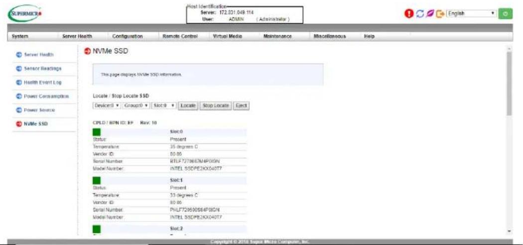
text_image
SUPERMICA Host Identification Server: 172.031.049.114 User: T ADMIN (Administrator) System Server Health Configuration Remote Control Virtual Media Maintenance Miscellaneous Help Server Health Sensor Readings Health Event Log Power Consumption Power Source NVMe SSD NVMe SSD This page displays NVMe SSD information. Locate / Stop Locate SSD Device:0 Group:0 Slot:0 Locate Stop Locate East CPLD / HPN ID: FP Rev: 10 Slot:0 Status: Present Temperature: 35 degrees C Vendor ID: 80.86 Serial Number: RTLF7270687MAPOGN Model Number: INTEL SSDPE2KX040T7 Slot:1 Status: Present Temperature: 33 degrees C Vendor ID: 80.86 Serial Number: PHLF729590964PIGN Model Number: INTEL SSDPE2KX040T7 Slot:2 Copyright © 2018 Sognet Micro Component, Inc.Figure 3-19. IPMI Screenshot
Replacing the Drive
- Insert the replacement drive.
- IPMI > Server Health > NVMe SSD
- Select Device, Group and slot and click Insert. The drive Status LED indicator flashes red, then turns off. The Activity LED turns blue.
Checking the Temperature of an NVMe Drive
There are two ways to check using IPMI.
Checking a Drive
- IPMI > Server Health > NVMe SSD – Shows the temperatures of all NVMe drives, as in Figure 3-4.
- IPMI > Server Health > Sensor Reading > NVME_SSD – Shows the single highest temperature among all the NVMe drives.
System Cooling
Fans
The chassis contains four 8-cm high-performance fans. Fan speed is controlled by IPMI depending on the system temperature. If a fan fails, the remaining fans will ramp up to full speed. The system will continue to run with a failed fan, although it may shut down if the heat gets too great. Replace any failed fan at your earliest convenience with the same model. Failed fans can be identified through the IPMI.
Changing a System Fan
-
Determine which fan has failed using IPMI, or if necessary, open the chassis while the system is running. Never run the server for long without the chassis cover.
-
Push the release tab and pull the failed fan from the chassis. Fans can be replaced while the system is running.
-
Replace the failed fan with an identical fan, available from Supermicro. Push the new fan into the housing, making sure the air flow direction is the same.
-
Power up the system and check that the fan is working properly and that the LED on the control panel has turned off. Finish by replacing the chassis cover.
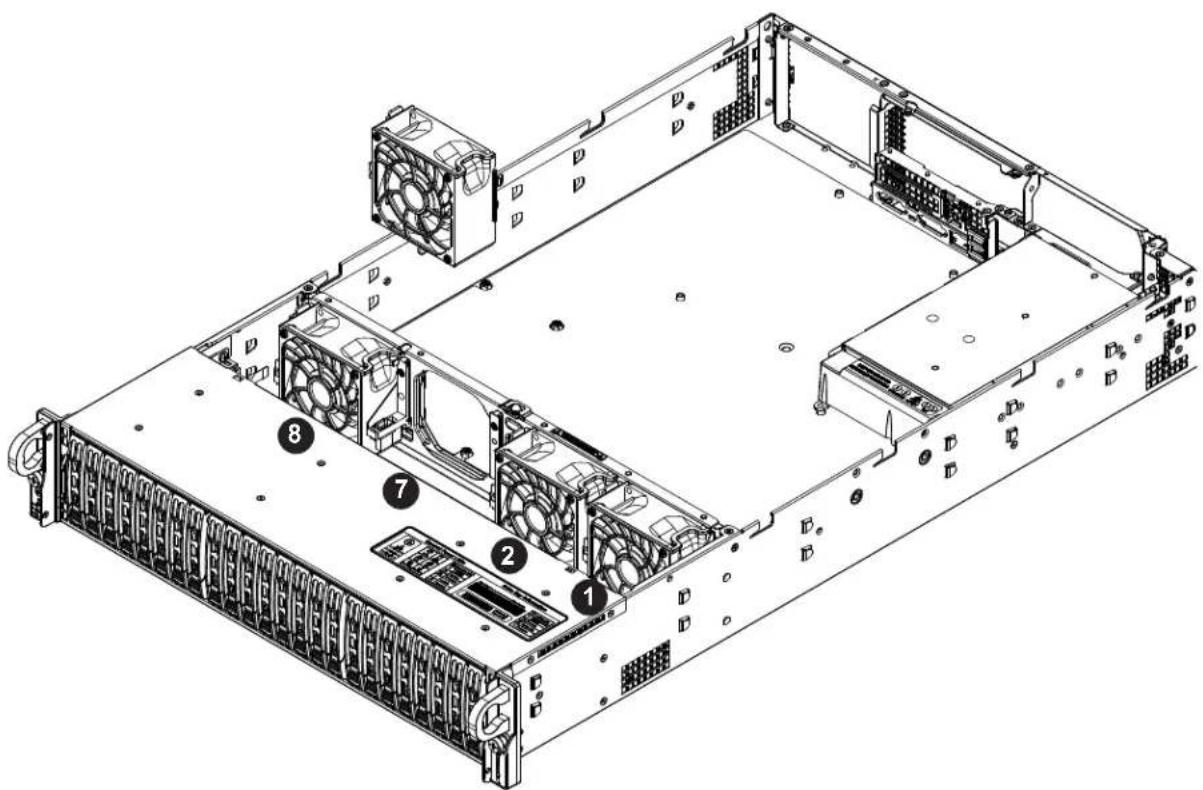
text_image
Technical diagram of a server rack with numbered components for identificationFigure 3-20. Fan Positions and Numbering
Installing the Air Shrouds
Air shrouds concentrate airflow to maximize fan efficiency. They do not require screws to install. If you use an M.2 SSD, a specialized shroud is installed instead of the standard shrouds. Some GPUs require specialized shrouds.
Installing the Standard Air Shrouds
- Position the air shrouds as illustrated in the figure below, sliding the front notch over the pin on the fan tray.
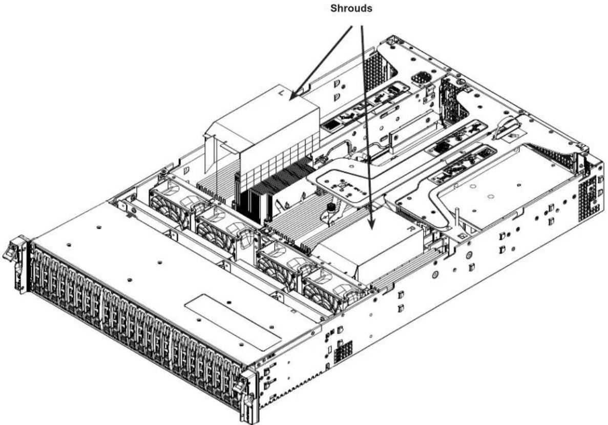
text_image
Shrouds p pNote: Graphics are for illustration purposes only. Your components may look slightly different
Figure 3-21. Installing the Standard Air Shrouds
Checking the Server Air Flow
- Make sure there are no objects to obstruct airflow in and out of the server.
- If you are using a front bezel, make sure the bezel filter is replaced periodically.
- Do not operate the server without drives or drive trays in the drive bays.
- Use only recommended server parts.
- Make sure no wires or foreign objects obstruct air flow through the chassis. Pull all excess cabling out of the airflow path or use shorter cables.
The control panel LEDs display system heat status. See “Control Panel” in Chapter 1 for details.
Overheating
There are several possible responses if the system overheats.
Overheat Temperature Setting
Some backplanes allow the overheat temperature to be set at 45, 50, or 55 by changing a jumper setting. For more information, consult the backplane user manual at www.supermicro.com. (Click Support, then the Manuals link.)
Responses
If the server overheats:
- Use the LEDs to determine the nature of the overheating condition.
- Confirm that the chassis covers are installed properly.
- Make sure all fans are present and operating normally.
- Check the routing of the cables.
- Verify that the heatsinks are installed properly.
Power Supply
The system features redundant power supplies and will continue to operate if one module fails. It should be replaced as soon as convenient. They can be changed without powering down the system. New units can be ordered directly from Supermicro or authorized distributors.
These power supplies are auto-switching capable. This feature enables them to automatically sense the input voltage and operate at a 100-120v or 180-240v.
Power Supply LEDs
On the rear of the power supply module, an LED displays the status.
• Solid Green: When illuminated, indicates that the power supply is on.
- Blinking Green: When blinking, indicates that the power supply is plugged in and turned off by the system.
- Blinking Amber: When blinking, indicates that the power supply has a warning condition and continues to operate.
- Solid Amber: When illuminated, indicates that the power supply is plugged in, and is in an abnormal state. The system might need service. Please contact Supermicro technical support.
Changing the Power Supply Module:
- Unplug the AC cord from the module to be replaced.
- On the back of the module, push the release tab sideways.
- Pull the module out using the handle.

text_image
PWS1 PWS2 Release TabsFigure 3-22. Power Supply Release Tabs
natural_image
Technical line drawing of a server rack unit with mounting hardware (no text or symbols)Figure 3-23. Replacing the Power Supply
- Push the new power supply module into the power bay until it clicks. Replace with the same model.
- Plug the AC power cord back into the module.
Chapter 4
Motherboard Connections
his section describes the connections, jumpers and LED indicators on the motherboard and provides pinout definitions. Not all connections are required. A motherboard layout indicating component locations may be found in Chapter 1.
Please review the Safety Precautions in Appendix A before installing or removing components.
4.1 Power Connections
Two power connections on the H11DSU-iN must be connected to the power supply. The wiring is included with the power supply.
- Two 25-pin primary proprietary power (PSU1/PSU2)
- Four 8-pin backplane power (P PWR1, BP PWR2, BP PWR3, BP PWR4)
• Three 8-pin GPU power (GPU PWR1, GPU PWR2, GPU PWR3)
Main Power Connector
Two proprietary main power headers are located at PSU1 and PSU2. Connect appropriate power supply units to these two headers to provide adequate power to your system.
Important: To provide adequate power to the motherboard, connect the both main power connectors to the power supply. Failure to do so may void the manufacturer's warranty on your power supply and motherboard.
Backplane 12V and 5V 8-pin Power Connectors
BP PWR1-4 are 8-pin 12V and 5V DC power inputs for the system backplane.
| Backplane 8-pin Power Pin Definitions |
| Pin# Definition |
| 1 - 4 Ground |
| 5 - 6 +12V |
| 7 - 8 +5V |
GPU 12V 8-pin Power Connectors
GPU PWR1-3 are 8-pin 12V DC power inputs for GPUs that are installed in the system PCIe slots.
| GPU 8-pin Power Pin Definitions | |
| Pin# | Definition |
| 1 - 4 | Ground |
| 5 - 8 | +12V |
4.2 Headers and Connectors
The data cables in the system have been carefully routed to maintain airflow efficiency. If you disconnect any of these cables, take care to re-route them as they were originally.
Important! Make sure the the cables do not come into contact with the fans.
Fan Headers
There are eight fan headers on the motherboard. These are 4-pin fan headers; pins 1-3 are backward compatible with traditional 3-pin fans. The onboard fan speeds are controlled by Thermal Management through the BIOS > Hardware Monitoring. Note: When using Thermal Management setting, use all 3-pin fans or all 4-pin fans.
| Fan HeaderPin Definitions | |
| Pin# | Definition |
| 1 | Ground (Black) |
| 2 | +12V (Red) |
| 3 | Tachometer |
| 4 | PWM Control |
SGPIO Header
The SGPIO1 (Serial General Purpose Input/Output) header is used to communicate with the enclosure management chip on the backplane.
| JSGPIO HeaderPin Definitions | ||
| Pin# Definition Pin# Definition | ||
| 1 Ground 2 DATA | IN | |
| 3 Ground 4 DATA | Out | |
| 5 Load 6 Ground | ||
| 7 Clock 8 NC | ||
NC = No Connection
Chassis Intrusion
A chassis intrusion header is located at JL1 on the motherboard. Attach the appropriate cable from the chassis to the header to inform you when the chassis is opened.
| Chassis Intrusion Pin Definitions |
| Pins Definition |
| 1 Intrusion Input |
| 2 Ground |
Disk-On-Module Power Connector
The Disk-On-Module (DOM) power connectors at JSD1 and JSD2 provide 5V power to a solid-state DOM storage device connected to one of the SATA ports. See the table below for pin definitions.
| DOM Power Pin Definitions | |
| Pin# Definition | |
| 1 5V | |
| 2 Ground | |
| 3 Ground | |
TPM Header/Port 80 Connector
The JTPM1 header is used to connect a Trusted Platform Module (TPM), which is available from Supermicro. A TPM is a security device that supports encryption and authentication in hard drives. It enables the motherboard to deny access if the TPM associated with the hard drive is not installed in the system.
For more information on TPM: http://www.supermicro.com/manuals/other/TPM.pdf.
| Trusted Platform Module Header Pin Definitions | ||
| Pin# Definition Pin# Definition | ||
| 1 LCLK 2 GND | ||
| 3 LFRAME# 4 No Pin | ||
| 5 LRESET# 6 NC | ||
| 7 LAD3 8 LAD2 | ||
| 9 3.3V 10 LAD1 | ||
| 11 LAD0 12 GND | ||
| 13 SMB_CLK4 (X) 14 SMB_DAT4 (X) | ||
| 15 P3V3_STBY 16 SERIRQ | ||
| 17 GND 18 LP_CLKRUN_L | ||
| 19 P3V3_STBY 20 LDRQ0_L | ||
IPMB System Management Bus Header
A System Management Bus header for IPMI 2.0 is located at JIPMB1. Connect the appropriate cable here to use the IPMB I ^2 C connection on your system.
| IPMB Header Pin Definitions | |
| Pin# | Definition |
| 1 | Data |
| 2 | Ground |
| 3 | Clock |
| 4 | No Connection |
UltraO Riser Card LAN LED Header
JF2 is a header for the Ultra Riser Card LAN LED header.
SATA Ports
The H11DSU-iN has 14 SATA 3.0 ports (SATA0-13) that are supported by the System on Chip.
NVMe Connections
Four NVM Express (NVMe) ports are located on the motherboard (two for each processor). These ports provide high-speed, low-latency PCIexp. 3.0 x4 connections directly from the CPU to NVMe Solid State (SSD) drives. This greatly increases SSD data-throughput performance and significantly reduces PCIe latency by simplifying driver/software requirements resulted from direct PCIe interface from the CPU to the NVMe SSD drives.
Control Panel
JF1 contains header pins for various control panel connections designed specifically for use with Supermicro chassis. See the figure below for the pin locations and definitions of the control panel buttons and LED indicators.
All JF1 wires have been bundled into a single cable to simplify this connection. Make sure the red wire plugs into pin 1 as marked on the motherboard. The other end connects to the control panel PCB board.
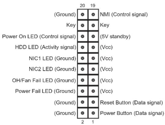
text_image
(Ground) Key Power On LED (Control signal) HDD LED (Activity signal) NIC1 LED (Ground) NIC2 LED (Ground) OH/Fan Fail LED (Ground) Power Fail LED (Ground) (Ground) (Ground) NMI (Control signal) Key (5V standby) (Vcc) (Vcc) (Vcc) (Vcc) Reset Button (Data signal) Power Button (Data signal)Figure 4-1. JF1: Control Panel Pins
Power Button
The Power Button connection is located on pins 1 and 2 of JF1. Momentarily contacting both pins will power on/off the system. This button can also be configured to function as a suspend button (with a setting in the BIOS - see Chapter 7). To turn off the power when the system is in suspend mode, press the button for 4 seconds or longer.
| Power ButtonPin Definitions (JF1) | |
| Pin# Definition | |
| 1 Signal | |
| 2 Ground | |
Reset Button
The Reset Button connection is located on pins 3 and 4 of JF1. Attach it to a hardware reset switch on the computer case.
| Reset ButtonPin Definitions (JF1) |
| Pin# Definition |
| 3 Reset |
| 4 Ground |
Power Fail LED
The Power Fail LED connection is located on pins 5 and 6 of JF1.
| Power Fail LEDPin Definitions (JF1) | |
| Pin# Definition | |
| 5 3.3V | |
| 6 PWR Supply Fail | |
Overheat (OH)/Fan Fail
Connect an LED cable to pins 7 and 8 of JF1 to use the Overheat/Fan Fail LED connections. The LED on pin 8 provides warnings of overheat or fan failure.
| OH/Fan Fail Indicator Status | |
| Status Definition | |
| Off Normal | |
| On Overheat | |
| Flashing Fan Fail | |
| OH/Fan Fail LEDPin Definitions (JF1) | |
| Pin# Definition | |
| 7 Blue | LED |
| 8 OH/Fan Fail LED | |
The NIC (Network Interface Controller) LED connection for LAN port 1 is located on pins 11 and 12 of JF1, and the LED connection for LAN Port 2 is on Pins 9 and 10. Attach the NIC LED cables here to display network activity.
| LAN1/LAN2 LEDPin Definitions (JF1) | |
| Pin# | Definition |
| 9 | NIC2 Activity LED |
| 10 | NIC2 Link LED |
| 11 | NIC1 Activity LED |
| 12 | NIC1 Link LED |
HDD LED/UID Switch
The HDD LED/UID Switch connection is located on pins 13 and 14 of JF1. Attach a cable to Pin 14 to show hard drive activity status. Attach a cable to Pin 13 to use UID switch. Refer to the table below for pin definitions.
| HDD LEDPin Definitions (JF1) |
| Pin# Definition |
| 13 3.3V Standby/UID Switch |
| 14 HDD Active |
Power LED
The Power LED connection is located on pins 15 and 16 of JF1.
| Power LEDPin Definitions (JF1) |
| Pin# Definition |
| 15 3.3V |
| 16 Power LED |
NMI Button
The non-maskable interrupt button header is located on pins 19 and 20 of JF1.
| NMI ButtonPin Definitions (JF1) |
| Pin# Definition |
| 19 Control |
| 20 Ground |
4.3 Ports
See the figure below for the locations and descriptions of the various I/O ports on the rear of the motherboard.

natural_image
Diagram of electronic device connectors including Ethernet, USB port, and VGA, arranged on a green circuit board (no text or symbols)Figure 4-2. Rear I/O Ports
| Rear I/O Ports | ||
| # Description # Description | ||
| 1. USB 3.0 Ports 4. UID button and LED | ||
| 2. IPMI LAN Port 5. VGA Port | ||
| 3 COM1 Port | ||
Universal Serial Bus (USB) Ports
There are two Universal Serial Bus 3.0 (0/1) ports located on the rear I/O panel and an additional two USB headers and a USB Type A header on the motherboard. These can be used to provide front USB access (cables not included).
Unit Identifier Switch/UID LED Indicator
A rear Unit Identifier (UID) switch and LED indicator are located on the rear side of the system. When you press the UID switch, both front and rear UID LED indicators are illuminated. Press the UID switch again to turn off the LEDs. The UID indicators provide easy identification of a system among a rack of many.
Note: UID can also be triggered using IPMI.
LAN Ports
There are two LAN ports on the chassis rear provided by the Ultra add-on card. There is also a dedicated IPMI LAN port on the I/O back panel. For more information on IPMI, refer to the IPMI User's Guide posted on our website at http://www.supermicro.com.
4.4 Jumpers
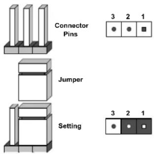
Explanation of Jumpers
To modify the operation of the motherboard, jumpers are used to choose between optional settings. Jumpers create shorts between two pins to change the function associated with it. Pin 1 is identified with a square solder pad on the printed circuit board. See the motherboard layout page for jumper locations.
Note: On a two-pin jumper, "Closed" means the jumper is on both pins and "Open" indicates the jumper is either on only one pin or has been completely removed.
text_image
Connector Pins Jumper Setting 3 2 1 ● ● ■ 3 2 1CMOS Clear
JBT1 is used to clear CMOS, which will also clear any passwords. Instead of pins, this jumper consists of contact pads to prevent accidentally clearing the contents of CMOS.
To Clear CMOS
- First power down the system and unplug the power cord(s).
- Remove the cover of the chassis to access the motherboard.
- Remove the onboard battery from the motherboard.
- Short the CMOS pads with a metal object such as a small screwdriver for at least four seconds.
- Remove the screwdriver (or shorting device).
- Replace the cover, reconnect the power cord(s) and power on the system.
Notes: Clearing CMOS will also clear all passwords.
Do not use the PW_ON connector to clear CMOS.

JBT1 contact pads
VGA Enable/Disable
JPG1 allows you to enable or disable the VGA port using the onboard graphics controller. The default setting is Enabled.
| VGA Enable/DisableJumper Settings | |
| Jumper Setting Definition | |
| Pins 1-2 Enabled | |
| Pins 2-3 Disabled | |
Watch Dog
JWD controls the Watch Dog function. Watch Dog is a monitor that can reboot the system when a software application hangs. Jumping pins 1-2 will cause Watch Dog to reset the system if an application hangs. Jumping pins 2-3 will generate a non-maskable interrupt signal for the application that hangs. Watch Dog must also be enabled in BIOS.
The default setting is Reset.
Note: When Watch Dog is enabled, the user must to write their own application software to disable it.
| Watch DogJumper Settings | |
| Jumper Setting Definition | |
| Pins 1-2 Reset | |
| Pins 2-3 NMI | |
| Open Disabled | |
4.5 LED Indicators
LAN LEDs
The LAN ports are located on the I/O back panel on the motherboard. Each Ethernet LAN port has two LEDs. The yellow LED indicates activity. Link LED, located on the left side of the LAN port, may be green, amber or off indicating the speed of the connection.

| LAN Link IndicatorLED Settings | |
| LED Color | Definition |
| Off No connection or 10 Mbps | |
| Green 100 | Mbps |
| Amber 25 | Gbps |
IPMI LAN LED
The LED indicates activity, while the Link LED indicates the speed of the connection.

text_image
IPMI LAN Link LED Activity LED| IPMI LAN LEDLink LED (left) | |
| LED Color Definition | |
| Amber: Solid 1 Gb/s | |
| Green: Solid 100 Mb/s |
Onboard Power LED
LE1 is an Onboard Power LED. When this LED is illuminated, it means power is present on the motherboard. In suspend mode this LED will blink on and off.
BMC Heartbeat LED
A BMC Heartbeat LED (LEDM1) blinks to indicate BMC is functioning normally.
Chapter 5
Software
After the hardware has been installed, you can install the Operating System (OS), configure RAID settings and install the drivers.
5.1 Microsoft Windows OS Installation
If you will be using RAID, you must configure RAID settings before installing the Windows OS and the RAID driver. Refer to the RAID Configuration User Guides posted on our website at www.supermicro.com/support/manuals.
Installing the OS
- Create a method to access the MS Windows installation ISO file. That might be a DVD, perhaps using an external USB/SATA DVD drive, or a USB flash drive, or the IPMI KVM console.
- Retrieve the proper RST/RSTe driver. Go to the Supermicro web page for your motherboard and click on "Download the Latest Drivers and Utilities", select the proper driver, and copy it to a USB flash drive.
- Boot from a bootable device with Windows OS installation. You can see a bootable device list by pressing F11 during the system startup.

text_image
Please select boot device: ATEN Virtual CDROM YSOJ → IPMI virtual drive (Legacy) ASUS SDRW-08D2S-U F601 → USB DVD device (Legacy) USB FLASH DRIVE PMAP → USB flash drive with OS installation (Legacy) IBA 40-10G Slot 1900 v1060 → PXE boot (Legacy) UEFI: ATEN Virtual CDROM YSOJ → IPMI virtual drive (UEFI) UEFI: ASUS SDRW-08D2S-U F601 → USB DVD device (UEFI) UEFI: Built-in EFI Shell Enter Setup ↑ and ↓ to move selection ENTER to select boot device ESC to boot using defaultsFigure 5-1. Select Boot Device
- During Windows Setup, continue to the dialog where you select the drives on which to install Windows. If the disk you want to use is not listed, click on "Load driver" link at the bottom left corner.
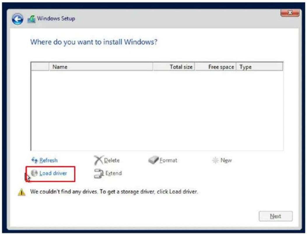
text_image
Where do you want to install Windows? Name Total size Free space Type Refresh Delete Format New Load driver Extend We couldn't find any drives. To get a storage driver, click Load driver. NextFigure 5-2. Load Driver Link
To load the driver, browse the USB flash drive for the proper driver files.
- For RAID, choose the SATA/sSATA RAID driver indicated then choose the storage drive on which you want to install it.
-
For non-RAID, choose the SATA/sSATA AHCI driver indicated then choose the storage drive on which you want to install it.
-
Once all devices are specified, continue with the installation.
- After the Windows OS installation has completed, the system will automatically reboot multiple times.
5.2 Driver Installation
The Supermicro website contains drivers and utilities for your system at www.supermicro.com/wftp/driver/AMD/SP3. Some of these must be installed, such as the chipset driver.
After accessing the website, go into the CDR_Images (in the parent directory of the above link) and locate the ISO file for your motherboard. Download this file to a USB flash drive or a DVD. (You may also use a utility to extract the ISO file if preferred.)
Another option is to go to the Supermicro website at http://www.supermicro.com/products/. Find the product page for your motherboard, and "Download the Latest Drivers and Utilities".
Insert the flash drive or disk and the screenshot shown below should appear.

text_image
SUPERMICRO X11SSV-LVDS Motherboard Drivers & Tools (Win7) SUPERMICRO Drivers & Tools AMD EPYC SoC H11DSU-iN SUPERMICRO Computer Inc. Intel Chipset INF files Microsoft .Net Framework 4.5.2 (Optional) Intel Graphics Media Accelerator Driver Realtek High Definition Audio Driver Intel SerialIO Driver Intel Rapid Storage Technology Intel USB 3.0 Drivers Intel Management Engine Intel PRO Network Connections Drivers Intel Software Guard Extensions Platform Software SUPERMICRO SuperDoctor 5 Build driver diskettes and manuals Auto Start Up Next Time For more information, please visit SUPERMICRO's web site.Figure 5-3. Driver & Tool Installation Screen
Note: Click the icons showing a hand writing on paper to view the readme files for each item. Click the computer icons to the right of these items to install each item (from top to the bottom) one at a time. After installing each item, you must re-boot the system before moving on to the next item on the list. The bottom icon with a CD on it allows you to view the entire contents.
5.3 SuperDoctor® 5
The Supermicro SuperDoctor 5 is a program that functions in a command-line or web-based interface for Windows and Linux operating systems. The program monitors such system health information as CPU temperature, system voltages, system power consumption, fan speed, and provides alerts via email or Simple Network Management Protocol (SNMP).
SuperDoctor 5 comes in local and remote management versions and can be used with Nagios to maximize your system monitoring needs. With SuperDoctor 5 Management Server (SSM Server), you can remotely control power on/off and reset chassis intrusion for multiple systems with SuperDoctor 5 or IPMI. SuperDoctor 5 Management Server monitors HTTP, FTP, and SMTP services to optimize the efficiency of your operation.
Note: The default User Name and Password for SuperDoctor 5 is ADMIN / ADMIN.
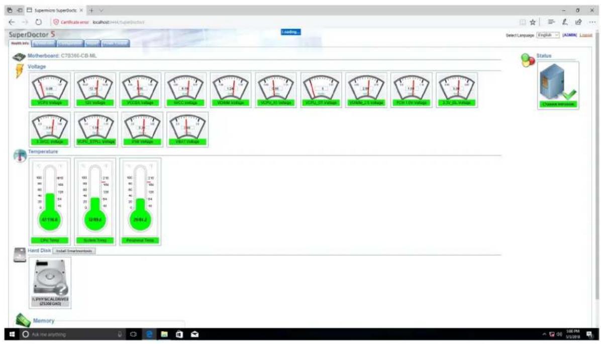
text_image
SuperDoctor 5 Home info: www.humanlab.com Certificate error: localhost:1044/superdoctor SuperDoctor 5 Select Language: English (ADMIN) Language Motherboard: C78366-CB-ML Voltage 0.0V 12.0V 14.0V 16.0V 18.0V 20.0V 22.0V 24.0V 26.0V 28.0V 30.0V 32.0V 34.0V 36.0V 38.0V 40.0V 42.0V 44.0V 46.0V 48.0V 50.0V 52.0V 54.0V 56.0V 58.0V 60.0V 62.0V 64.0V 66.0V 68.0V 70.0V 72.0V 74.0V 76.0V 78.0V 80.0V 82.0V 84.0V 86.0V 88.0V 90.0V 92.0V 94.0V 96.0V 98.0V 100.0V 102.0V 104.0V 106.0V 108.0V 110.0V 112.0V 114.0V 116.0V 118.0V 120.0V 122.0V 124.0V 126.0V 128.0V 130.0V 132.0V 134.0V 136.0V 138.0V 140.0V 142.0V 144.0V 146.0V 148.0V 150.0V 152.0V 154.0V 156.0V 158.0V 160.0V 162.0V 164.0V 166.0V 168.0V 170.0V 172.0V 174.0V 176.0V 178.0V 180.0V 182.0V 184.0V 186.0V 188.0V 190.0V 192.0V 194.0V 196.0V 198.0V 200.0V 202.0V 204.0V 206.0V 208.0V 210.0V 212.0V 214.0V 216.0V 218.0V 220.0V 222.0V 224.0V 226.0V 228.0V 230.0V 232.0V 234.0V 236.0V 238.0V 240.0VFigure 5-4. SuperDoctor 5 Interface Display Screen (Health Information)
5.4 IPMI
The H11DSU-iN supports the Intelligent Platform Management Interface (IPMI). IPMI provides remote access, monitoring and management through the baseboard management controller (BMC) and other management controllers distributed among different system modules. There are several BIOS settings that are related to IPMI. For general documentation and information on IPMI, visit our website at: http://www.supermicro.com/products/nfo/IPMI.cfm.
BMC ADMIN User Password
For security, each system is assigned a unique default BMC password for the ADMIN user. This can be found on a sticker on the chassis and a sticker on the motherboard. The sticker also displays the BMC MAC address.

text_image
BMC AC1F6BC07014 PWD SUOKJKJYZCFigure 5-5. BMC Password Label
See Chapter 1 for the location of the label.
Chapter 6
UEFI BIOS
(for 7001 Processor)
6.1 Introduction
This chapter describes the AMI BIOS setup utility for the H11DSU-iN and provides the instructions on navigating the setup screens. The BIOS is stored in a Flash EEPROM and can be updated.
Note: Due to periodic changes to the BIOS, some settings may have been added or deleted since this manual was published.
Starting BIOS Setup Utility
To enter the AMI BIOS setup utility screens, press the
The BIOS screens have three main frames. The large left frame displays options can be configured by the user. These are blue. When an option is selected, it is highlighted in white. Settings printed in Bold are the default values.
In the left frame, a "▶" indicates a submenu. Highlighting such an item and pressing the
The upper right frame displays helpful information for the user. The AMI BIOS has default informational messages built in. The manufacturer retains the option to include, omit, or change any of these informational messages.
The lower right frame lists navigational methods. The AMI BIOS setup utility uses a key-based navigation system called hot keys. Most of these hot keys can be used at any time during setup navigation. These keys include
Some system parameters may be changed.
6.2 Main Setup
When running the AMI BIOS setup utility, it starts with the Main screen. You can always return to it by selecting the Main tab on the top of the screen.
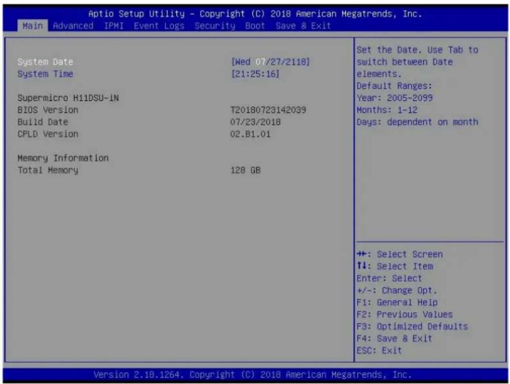
text_image
Aptio Setup Utility - Copyright (C) 2018 American Megatrends, Inc. Main Advanced IPMI Event Logs Security Boot Save & Exit System Date [Wed 07/27/2118] System Time [21:25:16] Supermicro H11DSU-IN BIOS Version T20180723142039 Build Date 07/23/2018 CPLD Version 02.81.01 Memory Information Total Memory 128 GB Set the Date. Use Tab to switch between Date elements. Default Ranges: Year: 2005-2099 Months: 1-12 Days: dependent on month +: Select Screen ↑↓: Select Item Enter: Select +/-: Change Opt. F1: General Help F2: Previous Values F3: Optimized Defaults F4: Save & Exit ESC: Exit Version 2.18.1264. Copyright (C) 2018 American Megatrends, Inc.The Main tab page allows you to set the date and time, and it displays system information.
System Date/System Time
Use this option to change the system date and time. Highlight System Date or System Time using the arrow keys. Enter new values using the keyboard. Press the
Note: The time is in the 24-hour format. For example, 5:30 P.M. appears as 17:30:00. The date's default value is 01/01/2016 after RTC reset.
Supermicro H11DSU-iN (Motherboard model)
BIOS Version
Build Date (of the BIOS)
CPLD (Complex Programmable Logic Device) Version: This item displays the CPLD version used in the system.
Memory Information
Total Memory (for the system)
Memory Speed
6.3 Advanced Setup Configurations
Use the arrow keys to select the Advanced tab and press
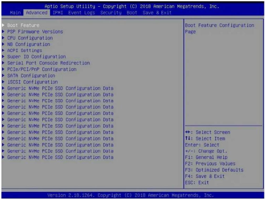
text_image
Aptio Setup Utility - Copyright (C) 2018 American Megatrends, Inc. Main Advanced IPMI Event Logs Security Boot Save & Exit ▶ Boot Feature ▶ PSP Firmware Versions ▶ CPU Configuration ▶ NB Configuration ▶ ACPI Settings ▶ Super IO Configuration ▶ Serial Port Console Redirection ▶ PCIe/PCI/PnP Configuration ▶ SATA Configuration ▶ iSCSI Configuration ▶ Generic NVMe PCIe SSD Configuration Data ▶ Generic NVMe PCIe SSD Configuration Data ▶ Generic NVMe PCIe SSD Configuration Data ▶ Generic NVMe PCIe SSD Configuration Data ▶ Generic NVMe PCIe SSD Configuration Data ▶ Generic NVMe PCIe SSD Configuration Data ▶ Generic NVMe PCIe SSD Configuration Data ▶ Generic NVMe PCIe SSD Configuration Data ▶ Generic NVMe PCIe SSD Configuration Data ▶ Generic NVMe PCIe SSD Configuration Data Boot Feature Configuration Page ++: Select Screen ↑↓: Select Item Enter: Select +/-: Change Opt. F1: General Help F2: Previous Values F3: Optimized Defaults F4: Save & Exit ESC: Exit Version 2.18.1264. Copyright (C) 2018 American Megatrends, Inc.Caution: Take caution when changing the Advanced settings. An incorrect value, a very high DRAM frequency, or an incorrect DRAM timing setting may make the system unstable. If this occurs, revert to the manufacture default settings.
▶Boot Feature
Quiet Boot
Use this feature to select the screen display between the POST messages and the OEM logo upon bootup. Select Disabled to display the POST messages. Select Enabled to display the OEM logo instead of the normal POST messages. The options are Enabled and Disabled.
Option ROM Messages
Use this feature to set the display mode for the Option ROM. Select Keep Current to display the current AddOn ROM setting. Select Force BIOS to use the Option ROM display set by the system BIOS. The options are Force BIOS and Keep Current.
Bootup NumLock State
Use this feature to set the Power on state for the
Wait For "F1" If Error
Use this feature to force the system to wait until the 'F1' key is pressed if an error occurs. The options are Disabled and Enabled.
INT19 (Interrupt 19) Trap Response
Interrupt 19 is the software interrupt that handles the boot disk function. When this item is set to Immediate, the ROM BIOS of the host adaptors will "capture" Interrupt 19 at bootup immediately and allow the drives that are attached to these host adaptors to function as bootable disks. If this item is set to Postponed, the ROM BIOS of the host adaptors will not capture Interrupt 19 immediately and allow the drives attached to these adaptors to function as bootable devices at bootup. The options are Immediate and Postponed.
Re-try Boot
If this item is enabled, the BIOS will automatically reboot the system from a specified boot device after its initial boot failure. The options are Disabled, Legacy Boot, and EFI Boot.
Power Configuration
Watch Dog Function
If enabled, the Watch Dog Timer will allow the system to reset or generate NMI based on jumper settings when it is expired for more than 5 minutes. The options are Disabled and Enabled.
Restore on AC Power Loss
Use this feature to set the power state after a power outage. Select Stay-Off for the system power to remain off after a power loss. Select Power-On for the system power to be turned on after a power loss. Select Last State to allow the system to resume its last power state before a power loss. The options are Stay Off, Power On, and Last State.
Power Button Function
This feature controls how the system shuts down when the power button is pressed. Select 4 Seconds Override for the user to power off the system after pressing and holding the power button for 4 seconds or longer. Select Instant Off to instantly power off the system as soon as the user presses the power button. The options are Instant Off and 4 Seconds Override.
▶PSP Firmware Versions
This section displays the Platform Security Processor (PSP) firmware versions.
PSP Directory Level 1 (Fixed)
- PSP Recovery BL Ver
- SMU FW Version
- ABL Version
-
APCB Version
-
APOB Version
- APPB Version
PSP Directory Level 2 (Updateable)
- PSP Bootloader Version
- SMU FW Version
- ABL Version
- APCB Version
- APOB Version
- APPB Version
▶Trusted Computing
Security Device Support
If this feature and the TPM jumper on the motherboard are both set to Enabled, onboard security devices will be enabled for TPM (Trusted Platform Module) support to enhance data integrity and network security. Please reboot the system for a change on this setting to take effect. The options are Disable and Enable.
TPM State
This software switch will enable or disable the installed security device. The options are Disable and Enable.
Pending Operation
This feature will schedule an operation for the security device, select TPM Clear to clear any pending operation. The options are None and TPM Clear
Device Select
Selecting TPM 1.2 will restrict support to TPM 1.2 devices, TPM 2.0 to TPM 2.0 devices and Auto will auto-select according to the version of the device installed, with the default set to TPM 2.0. The options are TPM 1.2, TPM 2.0 and Auto.
▶CPU Configuration
SMT Mode
Use this setting to specify Simultaneous Multithreading. Options include Off for 1T single thread and Auto for 2T two-thread if your system is capable of it.
Core Performance Boost
This setting is used to configure for Core Performance Boost. Options include Auto and Disabled.
Global C-state Control
This setting is used to configure for Global C-state Control. Options include Auto, Disabled and Enabled.
Downcore Control
This sets the number of cores to be used by your system. Once this option has been used to remove any cores, a power cycle is required in order for the future selections to take effect.
Options include TWO (1+1) , Two (2+0) , Three (3+0) , Four (2+2) , Four (4+0) , Six (3+3) and Auto. If unsure, leave this to Auto.
L1 Stream HW Prefetcher / L2 Stream HW Prefetcher
This setting is used to enable or disable the L1/L2 Stream Hardware Prefetcher. The options are Auto, Disabled and Enabled.
SVM Mode
This setting Enables or Disables CPU Virtualization.
SMEE
This setting Enables or Disables secure memory encryption control.
▶CPU1/CPU2 Information
These sections are for informational purposes. They will display some details about the detected CPUs on the motherboard, such as:
- CPU Version
• Number of Cores Running - Clock speed
- Processor Family
- Processor Model
- Microcode Patch Level
• L1 Instruction Cache (Size/Method)
• L1 Data Cache (Size/Method)
• L2 Data Cache (Size/Method)
• L3 Cache per Scoket (Size/Method)
▶NB Configuration
Determinism Slider
Use this setting to configure the Determinism Slider. Options include Auto, Power and Performance.
cTDP Control
Use this setting to configure the cTDP Control. Options include Manual and Auto.
IOMMU
Use this setting to enable/disable IOMMU. Options include Enabled, Disabled and Auto.
ACS Enable
Use this setting to enable/disable ACS. Options include Enabled, Disabled and Auto.
▶Memory Configuration
Memory Clock
This setting allows you to select different memory clock speed. Options include Auto and speed settings from 1333Mhz to 2666Mhz.
Memory Interleaving
This setting controls fabric level memory interleaving. Note that the channel, die and socket have requirements on memory populations and it will be ignored if the memory doesn't support the selected option. Options include None, Channel, Die, Socket and Auto.
Memory Interleaving Size
This setting controls the memory interleaving size. This determines the starting address of the interleave (bit 8, 9, 10 or 11). Options include 256 Bytes, 512 Bytes, 1 KB, 2 KB or Auto.
Chipset Interleaving
This setting controls interleave memory blocks across the DRAM chip for node 0. The options are Disabled and Auto.
BankGroupSwap
This setting controls the Bank Group Swap. The options are Enabled, Disabled and Auto.
▶CPU1/CPU2 Memory Information
These sections are for informational purposes. They will display some details about the detected memory according to each CPU on the motherboard, such as:
• Detected Size (per slot, in MB)
- Current Speed (MT/s)
▶ ACPI Settings
High Precision Event Timer
The High Precision Event Timer (HPET) can produce periodic interrupts and is used to synchronize multimedia streams, providing smooth playback and reducing the need to use other timestamp calculations. The options are Enabled and Disabled.
▶Super IO Configuration
The following Super IO information will display:
• Super IO Chip AST2500
▶ Serial Port 1 Configuration
Serial Port
Select Enabled to enable the selected onboard serial port. The options are Disabled and Enabled.
Device Settings
This item displays the status of a serial part specified by the user.
Change Settings
This feature specifies the base I/O port address and the Interrupt Request address of a serial port specified by the user. Select Auto to allow the BIOS to automatically assign the base I/O and IRQ address. The options are Auto, (IO=3F8h; IRQ=4); (IO=3F8h; IRQ=3, 4, 5, 6, 7, 9, 10, 11, 12); (IO=2F8h; IRQ=3, 4, 5, 6, 7, 9, 10, 11, 12); (IO=3E8h; IRQ=3, 4, 5, 6, 7, 9, 10, 11, 12); and (IO=2E8h; IRQ=3, 4, 5, 6, 7, 9, 10, 11, 12).
▶SOL Configuration
Serial Port
Select Enabled to enable the selected onboard serial port. The options are Disabled and Enabled.
Change Settings
This feature specifies the base I/O port address and the Interrupt Request address of a serial port specified by the user. Select Auto to allow the BIOS to automatically assign the base I/O and IRQ address. The options are Auto, (IO=2F8h; IRQ=3); (IO=3F8h; IRQ=3, 4, 5, 6, 7, 9, 10, 11, 12); (IO=2F8h; IRQ=3, 4, 5, 6, 7, 9, 10, 11, 12); (IO=3E8h; IRQ=3, 4, 5, 6, 7, 9, 10, 11, 12); and (IO=2E8h; IRQ=3, 4, 5, 6, 7, 9, 10, 11, 12).
▶Serial Port Console Redirection
COM1
Console Redirection
Select Enabled to enable console redirection support for a serial port specified by the user. The options are Enabled and Disabled.
*If the item above set to Enabled, the following items will become available for user's configuration:
▶Console Redirection Settings
Terminal Type
This feature allows the user to select the target terminal emulation type for Console Redirection. Select VT100 to use the ASCII Character set. Select VT100+ to add color and function key support. Select ANSI to use the Extended ASCII Character Set. Select VT-UTF8 to use UTF8 encoding to map Unicode characters into one or more bytes. The options are VT100, VT100+, VT-UTF8, and ANSI.
Bits per second
Use this feature to set the transmission speed for a serial port used in Console Redirection. Make sure that the same speed is used in the host computer and the client computer. A lower transmission speed may be required for long and busy lines. The options are 9600, 19200, 38400, 57600 and 115200 (bits per second).
Data Bits
Use this feature to set the data transmission size for Console Redirection. The options are 7 and 8.
Parity
A parity bit can be sent along with regular data bits to detect data transmission errors. Select Even if the parity bit is set to 0, and the number of 1's in data bits is even. Select Odd if the parity bit is set to 0, and the number of 1's in data bits is odd. Select None if you do not want to send a parity bit with your data bits in transmission. Select Mark to add a mark as a parity bit to be sent along with the data bits. Select Space to add a Space as a parity bit to be sent with your data bits. The options are None, Even, Odd, Mark, and Space.
Stop Bits
A stop bit indicates the end of a serial data packet. Select 1 Stop Bit for standard serial data communication. Select 2 Stop Bits if slower devices are used. The options are 1 and 2.
Flow Control
Use this feature to set the flow control for Console Redirection to prevent data loss caused by buffer overflow. Send a "Stop" signal to stop sending data when the receiving buffer
is full. Send a "Start" signal to start sending data when the receiving buffer is empty. The options are None and Hardware RTS/CTS.
VT-UTF8 Combo Key Support
Select Enabled to enable VT-UTF8 Combination Key support for ANSI/VT100 terminals. The options are Disabled and Enabled.
Recorder Mode
Select Enabled to capture the data displayed on a terminal and send it as text messages to a remote server. The options are Disabled and Enabled.
Resolution 100x31
Select Enabled for extended-terminal resolution support. The options are Disabled and Enabled.
Putty KeyPad
This feature selects the settings for Function Keys and KeyPad used for Putty, which is a terminal emulator designed for the Windows OS. The options are VT100, LINUX, XTERMR6, SC0, ESCN, and VT400.
SOL
Console Redirection
Select Enabled to enable SOL console redirection support for a serial port specified by the user. The options are Enabled and Disabled.
*If the item above set to Enabled, the following items will become available for user's configuration:
▶Console Redirection Settings
Terminal Type
This feature allows the user to select the target terminal emulation type for Console Redirection. Select VT100 to use the ASCII Character set. Select VT100+ to add color and function key support. Select ANSI to use the Extended ASCII Character Set. Select VT-UTF8 to use UTF8 encoding to map Unicode characters into one or more bytes. The options are VT100, VT100+, VT-UTF8, and ANSI.
Bits per second
Use this feature to set the transmission speed for a serial port used in Console Redirection. Make sure that the same speed is used in the host computer and the client computer. A lower transmission speed may be required for long and busy lines. The options are 9600, 19200, 38400, 57600 and 115200 (bits per second).
Data Bits
Use this feature to set the data transmission size for Console Redirection. The options are 7 and 8.
Parity
A parity bit can be sent along with regular data bits to detect data transmission errors. Select Even if the parity bit is set to 0, and the number of 1's in data bits is even. Select Odd if the parity bit is set to 0, and the number of 1's in data bits is odd. Select None if you do not want to send a parity bit with your data bits in transmission. Select Mark to add a mark as a parity bit to be sent along with the data bits. Select Space to add a Space as a parity bit to be sent with your data bits. The options are None, Even, Odd, Mark, and Space.
Stop Bits
A stop bit indicates the end of a serial data packet. Select 1 Stop Bit for standard serial data communication. Select 2 Stop Bits if slower devices are used. The options are 1 and 2.
Flow Control
Use this feature to set the flow control for Console Redirection to prevent data loss caused by buffer overflow. Send a "Stop" signal to stop sending data when the receiving buffer is full. Send a "Start" signal to start sending data when the receiving buffer is empty. The options are None and Hardware RTS/CTS.
VT-UTF8 Combo Key Support
Select Enabled to enable VT-UTF8 Combination Key support for ANSI/VT100 terminals. The options are Disabled and Enabled.
Recorder Mode
Select Enabled to capture the data displayed on a terminal and send it as text messages to a remote server. The options are Disabled and Enabled.
Resolution 100x31
Select Enabled for extended-terminal resolution support. The options are Disabled and Enabled.
Putty KeyPad
This feature selects the settings for Function Keys and KeyPad used for Putty, which is a terminal emulator designed for the Windows OS. The options are VT100, LINUX, XTERMR6, SC0, ESCN, and VT400.
Legacy Console Redirection
▶Legacy Console Redirection Settings
Redirection COM Port
For this setting, select a COM port to display redirection of Legacy OS and Legacy OPROM messages. Options include COM1 and SOL.
Resolution
For Legacy OS systems, use this setting to specify the number of Rows and Columns supported for redirection. Options include 80x24 and 80x25.
Redirect After Post
For this setting, when the Bootloader is selected, then the Legacy Console Redirection is disabled before booting to the legacy OS. If you select Always Enable, then the Legacy Console Redirection is enabled for legacy OS systems. Default option for this system is Always Enable.
Serial Port for Out-of-Band Management/Windows Emergency Management Services (EMS)
Console Redirection
Select Enabled to enable EMS console redirection support for a serial port specified by the user. The options are Enabled and Disabled.
*If the item above set to Enabled, the following items will become available for user's configuration:
▶ Console Redirection Settings
Out-of-Band Mgmt Port
The feature selects a serial port in a client server to be used by the Microsoft Windows Emergency Management Services (EMS) to communicate with a remote host server. The options are COM1, COM2 (Disabled), and AMT SOL.
Terminal Type
Use this feature to select the target terminal emulation type for Console Redirection. Select VT100 to use the ASCII character set. Select VT100+ to add color and function key support. Select ANSI to use the extended ASCII character set. Select VT-UTF8 to use UTF8 encoding to map Unicode characters into one or more bytes. The options are VT100, VT100+, VT-UTF8, and ANSI.
Bits per Second
This item sets the transmission speed for a serial port used in Console Redirection. Make sure that the same speed is used in the host computer and the client computer. A lower transmission speed may be required for long and busy lines. The options are 9600, 19200, 57600, and 115200 (bits per second).
Flow Control
Use this item to set the flow control for Console Redirection to prevent data loss caused by buffer overflow. Send a "Stop" signal to stop sending data when the receiving buffer is full. Send a "Start" signal to start sending data when the receiving buffer is empty. The options are None, Hardware RTS/CTS, and Software Xon/Xoff.
Data Bits
Parity
Stop Bits
▶PCIe/PCI/PnP Configuration
This menu provides PCIe/PCI/PnP configuration settings and information.
PCI Bus Driver Version
Above 4G Decoding
This setting Enables or Disables 64-bit capable devices ability to be decoded in above 4G address space (only if the system supports 64-bit PCI decoding).
SR-IOV Support
If the system has SR-IOV capable PCI-E devices, this setting will Enable or Disable the Single Root IO Virtualization Support for the system.
PCIe Spread Spectrum
Use this setting to Enable or Disable PCI-E Spread Spectrum for your system.
Target Link Speed
If supported by hardware and set to Force to x.S GT/S (x being a value of 2.5, 5.0 or 8.0) for Downstream Ports, this sets an upper limit on Link Operational Speed by restricting the values advertised by the UPstream component in its training sequences. When Auto is selected, the HW initialized data will be used.
VGA Priority
Use this setting to select between onboard or offboard VGA support The options are Onboard and Offboard
NVMe Firmware Source
Use this setting to select between the AMI Native firmware support or the device vendor-defined firmware support. The options are AMI Native Support and Vendor Defined Firmware.
M.2 (AHCI) Firmware Source
Use this setting to select between the AMI Native firmware support or the device vendor-defined firmware support. The options are AMI Native Support and Vendor Defined Firmware.
RSC-W2-66 Slot 1 PCI-E x16 OPROM
This setting enables or disables the listed PCI/PCIX/PCIe Slot OPROM option. Options include Disabled, Legacy or EFI.
RSC-W2-66 Slot 2 PCI-E x16 OPROM
This setting enables or disables the listed PCI/PCIX/PCIe Slot OPROM option. Options include Disabled, Legacy or EFI.
RSC-WR-6 Slot 1 PCI-E 4.0 x16 OPROM
This setting enables or disables the listed PCI/PCIX/PCIe Slot OPROM option. Options include Disabled, Legacy or EFI.
AOC-2UR68-m2TS Slot 2 PCI-E x16 OPROM
This setting enables or disables the listed PCI/PCIX/PCIe Slot OPROM option. Options include Disabled, Legacy or EFI.
AOC-2UR68-m2TS Slot 3 PCI-E x8 OPROM
This setting enables or disables the listed PCI/PCIX/PCIe Slot OPROM option. Options include Disabled, Legacy or EFI.
AOC-2UR68-m2TS Slot 1 PCI-E x8 OPROM
This setting enables or disables the listed PCI/PCIX/PCIe Slot OPROM option. Options include Disabled, Legacy or EFI.
Onboard LAN Option ROM Type
Use this setting to select which firmware type to be loaded for onboard LAN on the system. Options include Legacy and EFI.
Onboard LAN1 Option ROM
Use this setting to select which firmware function is to be loaded for onboard LAN1 on the system. Options include Disabled and Legacy.
Onboard LAN2 Option ROM
Use this setting to select which firmware function is to be loaded for onboard LAN2 on the system. Options include Disabled and Legacy.
P1\_NVMe0 OpROM
Use this setting to select which firmware function is to be loaded for P1_NVMe0 OpROM on the system. Options include Disabled, Legacy and EFI.
P1\_NVMe1 OpROM
Use this setting to select which firmware function is to be loaded for P1_NVMe1 OpROM on the system. Options include Disabled, Legacy and EFI.
P2\_NVMe0 OpROM
Use this setting to select which firmware function is to be loaded for P2_NVMe0 OpROM on the system. Options include Disabled, Legacy and EFI.
P2\_NVMe1 OpROM
Use this setting to select which firmware function is to be loaded for P2_NVMe1 OpROM on the system. Options include Disabled, Legacy and EFI.
Onboard Video Option ROM
This setting selects which onboard video firmware type to be selected. Options include Disabled, Legacy and EFI.
▶Network Stack Configuration
Network Stack
This setting allows you to Enable or Disable the UEFI Network Stack.
Ipv4 PXE Support
This setting allows you to Enable or Disable IPv4 PXE boot support. If disabled, IPv4 PXE boot support will not be available.
Ipv4 HTTP Support
This setting allows you to Enable or Disable IPv4 HTTP boot support. If disabled, IPv4 HTTP boot support will not be available.
Ipv6 PXE Support
This setting allows you to Enable or Disable IPv6 PXE boot support. If disabled, IPv6 PXE boot support will not be available.
Ipv6 HTTP Support
This setting allows you to Enable or Disable IPv6 HTTP boot support. If disabled, IPv6 HTTP boot support will not be available.
PXE Boot Wait Time
This setting allows you to set in a number field the wait time to press the ESC key to abort the PXE boot. Default is 0.
Media Detect Count
This setting allows you set in a number field the number of times presence of media will be checked. Default is 1.
▶SATA Configuration
This section displays the detected SATA devices installed on the system.
SATA Controller
This setting enables or disables the on chip SATA controller. The options are Enabled, Disabled or Auto.
SATA Hot Plug
This setting enables or disables the on chip SATA hot plug feature. The options are Enabled, Disabled.
▶SATA Information
This section displays information on the detected SATA devices:
• CPU1 SATA0 \~ CPU1 SATA7
▶iSCSI Configuration
iSCSI Initiator Name
This feature allows the user to enter the unique name of the iSCSI Initiator in IQN format. Once the name of the iSCSI Initiator is entered into the system, configure the proper settings for the following items.
▶ Add an Attempt
▶ Delete Attempts
▶ Change Attempt Order
6.4 IPMI
Use this tab page to configure Intelligent Platform Management Interface (IPMI) settings.

text_image
Aptio Setup Utility - Copyright (C) 2018 American Megatrends, Inc. Main Advanced IPMI Event Logs Security Boot Save & Exit BMC Firmware Revision 1.36 IPMI STATUS Working ► System Event Log ► BMC Network Configuration PressBMC Firmware Revision
This item indicates the IPMI firmware revision used in your system.
IPMI Status (Baseboard Management Controller)
This item indicates the status of the IPMI firmware installed in your system.
▶System Event Log
Enabling/Disabling Options
SEL Components
Select Enabled for all system event logging at bootup. The options are Enabled and Disabled.
Erasing Settings
Erase SEL
Select Yes, On next reset to erase all system event logs upon next system reboot. Select Yes, On every reset to erase all system event logs upon each system reboot. Select No
to keep all system event logs after each system reboot. The options are No, Yes, On next reset, and Yes, On every reset.
When SEL is Full
This feature allows the user to decide what the BIOS should do when the system event log is full. Select Erase Immediately to erase all events in the log when the system event log is full. The options are Do Nothing and Erase Immediately.
Note: After making changes on a setting, be sure to reboot the system for the changes to take effect.
▶BMC Network Configuration
BMC Network Configuration
Update IPMI LAN Configuration
Select Yes for the BIOS to implement all IP/MAC address changes at the next system boot. The options are No and Yes.
Configure IPV4 Support
This section displays static configuration features for IPV4 support.
IPMI LAN Selection
This item displays the IPMI LAN setting. The default setting is Failover.
IPMI Network Link Status
This item displays the IPMI Network Link status. The default setting is Shared LAN.
*If the item above is set to Yes, the following item will become available for configuration:
Configuration Address Source
This feature allows the user to select the source of the IP address for this computer. If Static is selected, you will need to know the IP address of this computer and enter it to the system manually in the field. If DHCP is selected, the BIOS will search for a DHCP (Dynamic Host Configuration Protocol) server in the network that is attached to and request the next available IP address for this computer. The options are DHCP and Static.
*If the item above is set to Static, the following items will become available for configuration:
Station IP Address
This item displays the Station IP address for this computer. This should be in decimal and in dotted quad form.
Subnet Mask
This item displays the sub-network that this computer belongs to. The value of each three-digit number separated by dots should not exceed 255.
Station MAC Address
This item displays the Station MAC address for this computer. Mac addresses are 6 two-digit hexadecimal numbers.
Gateway IP Address
This item displays the Gateway IP address for this computer. This should be in decimal and in dotted quad form (i.e., 172.31.0.1).
VLAN
This item configures the virtual LAN settings. The options are Disabled and Enable.
Configure IPV6 Support
This section displays configuration features for IPV6 support.
IPV6 Support
Use this feature to enable IPV6 support. The options are Enabled and Disabled.
Configuration Address Source
This feature allows the user to select the source of the IP address for this computer. If Static is selected, you will need to know the IP address of this computer and enter it to the system manually in the field. If DHCP is selected, the BIOS will search for a DHCP (Dynamic Host Configuration Protocol) server in the network that is attached to and request the next available IP address for this computer. The options are Unspecified, Static, and DHCP.
\*If the item "Configuration Address Source" above is set to Static, the following items will become available for configuration:
- Station IPV6 Address
- Prefix Length
• IPV6 Router1 IP Address
• IPV6 Address Status
• IPV6 DHCP Algorithm
6.5 Event Logs
Use this tab page to configure Event Log settings.
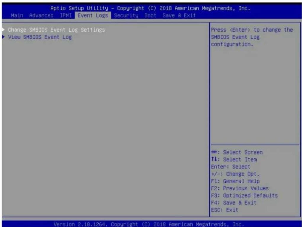
text_image
Aptio Setup Utility - Copyright (C) 2018 American Megatrends, Inc. Main Advanced IPMI Event Logs Security Boot Save & Exit Change SMBIOS Event Log Settings View SMBIOS Event Log Press▶Change SMBIOS Event Log Settings
This feature allows the user to configure SMBIOS Event settings.
Enabling/Disabling Options
SMBIOS Event Log
Select Enabled to enable SMBIOS (System Management BIOS) Event Logging during system boot. The options are Enabled and Disabled.
Erasing Settings
Erase Event Log
Select Yes to erase all error events in the SMBIOS (System Management BIOS) log before an event logging is initialized at bootup. The options are No, Yes, Next reset, and Yes, every reset.
When Log is Full
Select Erase Immediately to immediately erase all errors in the SMBIOS event log when the event log is full. Select Do Nothing for the system to do nothing when the SMBIOS event log is full. The options are Do Nothing and Erase Immediately.
SMBIOS Event Log Standard Settings
Log System Boot Event
Select Enabled to log system boot events. The options are Disabled and Enabled.
MECI (Multiple Event Count Increment)
Enter the increment value for the multiple event counter. Enter a number between 1 to 255. The default setting is 1.
METW (Multiple Event Count Time Window)
This item is used to determine how long (in minutes) the multiple event counter should wait before generating a new event log. Enter a number between 0 to 99. The default setting is 60.
Note: Please reboot the system for these changes to take effect.
▶View SMBIOS Event Log
When Event Logging is on, this item allows the user to view the entries in the SMBIOS event log. The following categories are displayed:
Date/Time/Error Code/Severity
6.6 Security
Use this tab page to configure Security settings.
| Aptio Setup Utility - Copyright (C) 2018 American Megatrends, Inc. Main Advanced IPMI Event Logs Security Boot Save & Exit | |
| Administrator Password Not Installed User Password Not Installed | Set Administrator Password |
| Password Description | |
| If the Administrator's / User's password is set, then this only limits access to Setup and is asked for when entering Setup. Please set Administrator's password first in order to set User's password, if clear Administrator's password, the User's password will be cleared as well. | |
| The password length must be in the following range: | |
| Minimum length 3 Maximum length 20 | |
| Administrator Password Password Check [Setup] | +: Select Screen ↑↓: Select Item Enter: Select +/-: Change Opt. F1: General Help F2: Previous Values F3: Optimized Defaults F4: Save & Exit ESC: Exit |
| · Secure Boot | |
| Version 2.18.1264. Copyright (C) 2018 American Megatrends, Inc. | |
Administrator Password
Press Enter to create a new, or change an existing Administrator password. Note that if the Administrator Password is erased, the User Password will be cleared as well.
User Password
Press Enter to create a new, or change an existing User password.
Password Check
Select Setup for the system to check for a password at Setup. Select Always for the system to check for a password at bootup or upon entering the BIOS Setup utility. The options are Setup and Always.
▶Secure Boot
This section contains options and menus for securing your boot mode and for key management.
Secure Boot
This option allows you specify when the Platform Key (PK) is enrolled. When enabled, the System Mode is user deployed, and the CSM function is disabled. Options include Enabled and Disabled.
Secure Boot Mode
Use this item to select the secure boot mode. The options are Standard and Custom.
CSM Support
Select Enabled to support the EFI Compatibility Support Module (CSM), which provides compatibility support for traditional legacy BIOS for system boot. The options are Disabled and Enabled.
▶Key Management
This submenu allows the user to configure the following Key Management settings.
▶Enroll All Factory Default Keys
Select Yes to install all default secure keys set by the manufacturer. The options are Yes and No.
▶Enroll EFI Image
This allows the image to run in Secure Boot Mode, and enroll SHA256 hash of the binary into an Authorized Signature Database (db).
▶ Save All Secure Boot Variables
This feature allows the user to decide if all secure boot variables should be saved.
▶ Platform Key (PK)
This feature allows the user to configure the settings of the platform keys.
Set New Key
Select Yes to load the new platform keys (PK) from the manufacturer's defaults. Select No to load the platform keys from a file. The options are Yes and No.
Provision Factory Default Keys
Select Enabled to install the default Secure-Boot keys set by the manufacturer. The options are Disabled and Enabled.
▶Key Exchange Keys
Set New Key
Select Yes to load the KEK from the manufacturer's defaults. Select No to load the KEK from a file. The options are Yes and No.
Append Key
Select Yes to add the KEK from the manufacturer's defaults list to the existing KEK. Select No to load the KEK from a file. The options are Yes and No.
▶ Authorized Signatures
Set New Key
Select Yes to load the database from the manufacturer's defaults. Select No to load the DB from a file. The options are Yes and No.
Append Key
Select Yes to add the database from the manufacturer's defaults to the existing DB. Select No to load the DB from a file. The options are Yes and No.
▶Forbidden Signatures
Set New Key
Select Yes to load the DBX from the manufacturer's defaults. Select No to load the DBX from a file. The options are Yes and No.
Append Key
Select Yes to add the DBX from the manufacturer's defaults to the existing DBX. Select No to load the DBX from a file. The options are Yes and No.
▶ Authorized TimeStamps
Set New Key
Select Yes to load the DBT from the manufacturer's defaults. Select No to load the DBT from a file. The options are Yes and No.
Append Key
Select Yes to add the DBT from the manufacturer's defaults list to the existing DBT. Select No to load the DBT from a file. The options are Yes and No.
▶OsRecovery Signature
This item uploads and installs an OSRecovery Signature. You may select options for Set New for a factory default key, or select Append to get it from a file. The file formats accepted are:
1) Public Key Certificate
a. EFI Signature List
b. EFI CERT X509 (DER Encoded)
c. EFI CERT RSA2048 (bin)
d. EFI SERT SHA256 (bin)
2) EFI Time Based Authenticated Variable
When prompted, select "Yes" to load Factory Defaults or "No" to load from a file.
6.7 Boot
Use this tab page to configure Boot Settings.
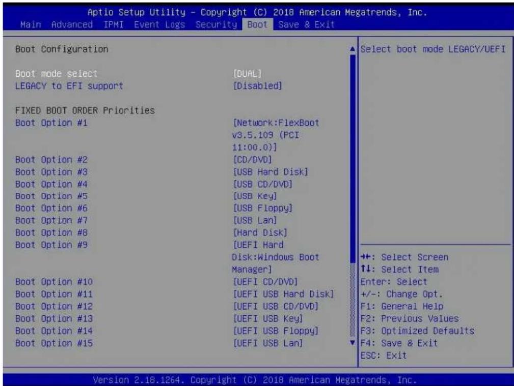
text_image
Aptio Setup Utility - Copyright (C) 2018 American Megatrends, Inc. Main Advanced IPMI Event Logs Security Boot Save & Exit Boot Configuration Boot mode select [DUAL] LEGACY to EFI support [Disabled] FIXED BOOT ORDER Priorities Boot Option #1 [Network:FlexBoot v3.5.109 (PCI 11:00.0)] Boot Option #2 [CD/DVD] Boot Option #3 [USB Hard Disk] Boot Option #4 [USB CD/DVD] Boot Option #5 [USB Key] Boot Option #6 [USB Floppy] Boot Option #7 [USB Lan] Boot Option #8 [Hard Disk] Boot Option #9 [UEFI Hard Disk:Windows Boot Manager] Boot Option #10 [UEFI CD/DVD] Boot Option #11 [UEFI USB Hard Disk] Boot Option #12 [UEFI USB CD/DVD] Boot Option #13 [UEFI USB Key] Boot Option #14 [UEFI USB Floppy] Boot Option #15 [UEFI USB Lan] Select boot mode LEGACY/UEFI +: Select Screen ↑↓: Select Item Enter: Select +/-: Change Opt. F1: General Help F2: Previous Values F3: Optimized Defaults F4: Save & Exit ESC: Exit Version 2.18.1264. Copyright (C) 2018 American Megatrends, Inc.Boot Mode Select
Use this item to select the type of device that the system is going to boot from. The options are LEGACY, UEFI, and DUAL. The default setting is DUAL.
Legacy to EFI Support
This option Enables or Disables the system to boot to an EFI OS after the boot failed from the legacy boot order.
FIXED BOOT ORDER Priorities Section
This option prioritizes the order of bootable devices that the system to boot from. Press
▶ Delete Boot Option
Use this feature to remove a pre-defined boot device from which the system will boot during startup. The settings are [any pre-defined boot device].
▶UEFI Application Boot Priorities
This feature allows the user to specify which UEFI devices are boot devices.
• UEFI Boot Order #1
▶Hard Disk Drive BBS Priorities
This feature allows the user to specify which hard disk drive devices are boot devices.
6.8 Save & Exit
Use this tab page to configure Save & Exit settings.
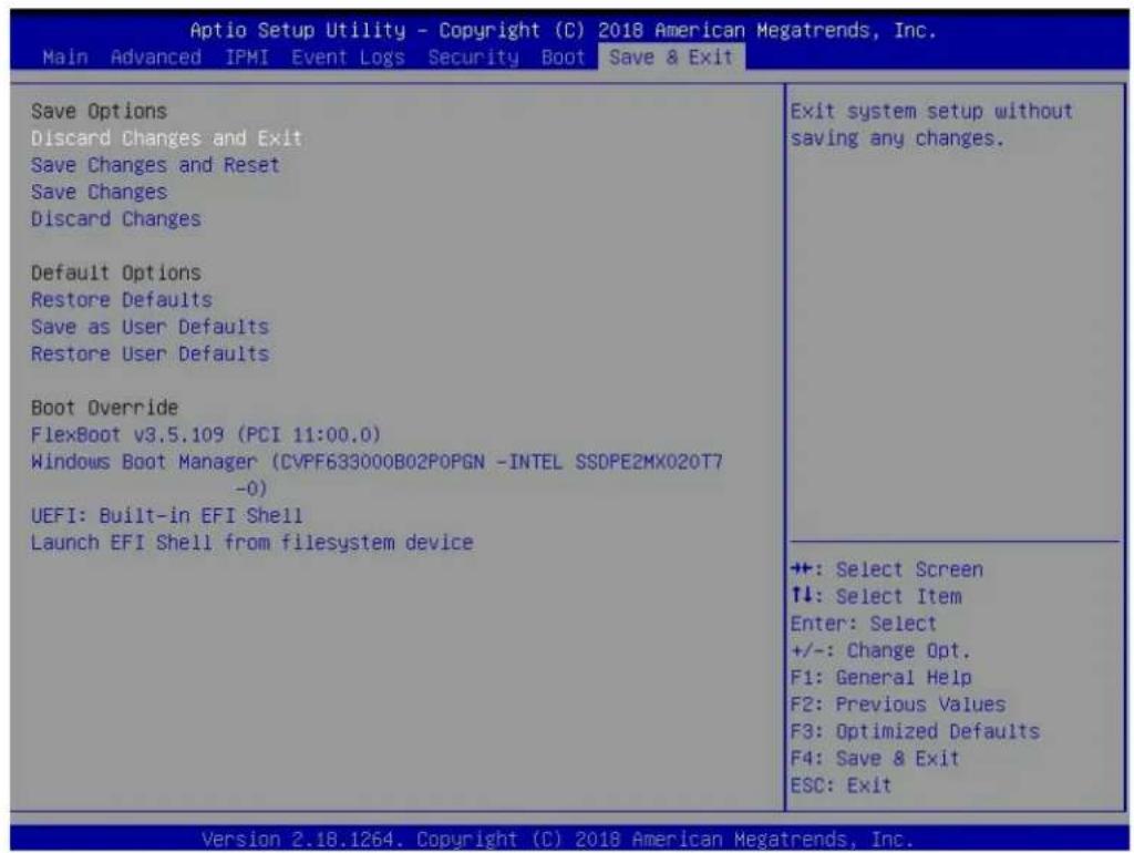
text_image
Aptio Setup Utility - Copyright (C) 2018 American Megatrends, Inc. Main Advanced IPMI Event Logs Security Boot Save & Exit Save Options Discard Changes and Exit Save Changes and Reset Save Changes Discard Changes Default Options Restore Defaults Save as User Defaults Restore User Defaults Boot Override FlexBoot v3.5.109 (PCI 11:00.0) Windows Boot Manager (CVPF633000B02P0PGN -INTEL SSDPE2MX020T7 -0) UEFI: Built-in EFI Shell Launch EFI Shell from filesystem device Exit system setup without saving any changes. ++: Select Screen ↑↓: Select Item Enter: Select +/-: Change Opt. F1: General Help F2: Previous Values F3: Optimized Defaults F4: Save & Exit ESC: Exit Version 2.18.1264. Copyright (C) 2018 American Megatrends, Inc.Discard Changes and Exit
Select this option to quit the BIOS Setup without making any permanent changes to the system configuration, and reboot the computer. Select Discard Changes and Exit from the Exit menu and press
Save Changes and Reset
Select this option to reset the system after saving the changes.
Save Changes
After completing the system configuration changes, select this option to save the changes you have made. This will not reset (reboot) the system.
Discard Changes
Select this option and press
Default Options
Restore Defaults
To set this feature, select Restore Defaults from the Save & Exit menu and press
Save as User Defaults
To set this feature, select Save as User Defaults from the Exit menu and press
To set this feature, select Restore User Defaults from the Exit menu and press
Boot Override Section
Listed on this section are other boot options for the system (i.e., Built-in EFI shell). Select an option and press
6.9 BIOS Update Using IPMI
If necessary, the system BIOS can be updated using IPMI. Documentation on IPMI is available at http://www.supermicro.com/products/nfo/IPMI.cfm.
- Download the BIOS file using the link on the server web page. Unzip and save it.
- Access the IPMI web interface. Enter the IP address and log in. The default username and password are ADMIN/ADMIN. (For details on IPMI, use the link above.)
- Click the Maintenance tab, then BIOS Update.

text_image
http://172.31.47.171/cgi/url_redirect.cgi?url_name=mainmenu Certificate error 172.31.47.171 Edit View Favorites Tools Help SUPERMICR Host Identification Server: 172.031.047 User: ADMIN System Server Health Configuration Remote Control Virtual Media Maintenance Miscellaneous System FRU Reading System Firmware Revision : 01.06 IP address : 172.031.047.171 Firmware Build Time : 09/05/2017 BMC MAC address : 0c:c4:7a:88:1c:0f BIOS Version : 1.0 System LAN1 MAC address : ac:1f:6b:05 BIOS Build Time : 08/24/2017 System LAN2 MAC address : ac:1f:6b:05 Redfish Version : 1.0.1 CPLD Version : 02.b4.98 Remote Console Preview Refresh Preview Image Maintenance Firmware Update Unit Reset IKVM Reset Factory Default IPMI Configuration System Event Log BIOS Update Trouble ShootingFigure 6-1. IPMI Maintenance Tab
- Browse to select the saved BIOS file and click Open.
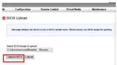
text_image
BIO5 Upload This page displays the device is now in BIOS Update mode. Please upload your BIOS image for updating. Select BIOS image to upload C:\Users\Normami\Desktop\Browse... Upload BIOS CancelFigure 6-2. Browse and Upload Dialog
- Click the Upload BIOS button. The message appears, "Uploading image & checking BIOS information... Please wait. This may take a while."

flowchart
graph TD
    A["Start Button"] --> B["Module Name: BIOS_FW"]
    B --> C{Preserve ME region}
    B --> D{Preserve NVRAM}
    B --> E{Preserve SMBIOS}
    E --> F["Start Upgrade"]
    E --> G["Cancel"]
    H["Clear Checkboxes"] --> I["Existing Date: 8/24/2017"]
    I --> J["New Date: 9/14/2017"]
    J --> K["Verify Date"]
Figure 6-3. Start Upgrade Dialog
- In the Start Upgrade dialog, make sure the three checkboxes are not checked, and verify the date of the BIOS file you uploaded before proceeding.
- Click the Start Upgrade button.
Chapter 7
UEFI BIOS
(for 7002 Processor)
7.1 Introduction
This chapter describes the AMI BIOS setup utility for the H11DSU-iN and provides the instructions on navigating the setup screens. The BIOS is stored in a Flash EEPROM and can be updated.
Note: Due to periodic changes to the BIOS, some settings may have been added or deleted since this manual was published.
Starting BIOS Setup Utility
To enter the AMI BIOS setup utility screens, press the
The BIOS screens have three main frames. The large left frame displays options can be configured by the user. These are blue. When an option is selected, it is highlighted in white. Settings printed in Bold are the default values.
In the left frame, a "▶" indicates a submenu. Highlighting such an item and pressing the
The upper right frame displays helpful information for the user. The AMI BIOS has default informational messages built in. The manufacturer retains the option to include, omit, or change any of these informational messages.
The lower right frame lists navigational methods. The AMI BIOS setup utility uses a key-based navigation system called hot keys. Most of these hot keys can be used at any time during setup navigation. These keys include
Some system parameters may be changed.
7.2 Main Setup
When running the AMI BIOS setup utility, it starts with the Main screen. You can always return to it by selecting the Main tab on the top of the screen.

text_image
Aptio Setup Utility - Copyright (C) 2018 American Megatrends, Inc. Main Advanced IPMI Event Logs Security Boot Save & Exit System Date [Wed 07/27/2118] System Time [21:25:16] Supermicro H11DSU-IN BIOS Version T20180723142039 Build Date 07/23/2018 CPLD Version 02.81.01 Memory Information Total Memory 128 GB Set the Date. Use Tab to switch between Date elements. Default Ranges: Year: 2005-2099 Months: 1-12 Days: dependent on month +: Select Screen ↑↓: Select Item Enter: Select +/-: Change Opt. F1: General Help F2: Previous Values F3: Optimized Defaults F4: Save & Exit ESC: Exit Version 2.18.1264. Copyright (C) 2018 American Megatrends, Inc.The Main tab page allows you to set the date and time, and it displays system information.
System Date/System Time
Use this option to change the system date and time. Highlight System Date or System Time using the arrow keys. Enter new values using the keyboard. Press the
Note: The time is in the 24-hour format. For example, 5:30 P.M. appears as 17:30:00. The date's default value is 01/01/2016 after RTC reset.
Supermicro H11DSU-iN (Motherboard model)
BIOS Version
Build Date (of the BIOS)
CPLD (Complex Programmable Logic Device) Version: This item displays the CPLD version used in the system.
Memory Information
Total Memory (for the system)
Memory Speed
7.3 Advanced Setup Configurations
Use the arrow keys to select the Advanced tab and press

text_image
Aptio Setup Utility - Copyright (C) 2018 American Megatrends, Inc. Main Advanced IPMI Event Logs Security Boot Save & Exit ▶ Boot Feature ▶ PSP Firmware Versions ▶ CPU Configuration ▶ NB Configuration ▶ ACPI Settings ▶ Super IO Configuration ▶ Serial Port Console Redirection ▶ PCIe/PCI/PnP Configuration ▶ SATA Configuration ▶ iSCSI Configuration ▶ Generic NVMe PCIe SSD Configuration Data ▶ Generic NVMe PCIe SSD Configuration Data ▶ Generic NVMe PCIe SSD Configuration Data ▶ Generic NVMe PCIe SSD Configuration Data ▶ Generic NVMe PCIe SSD Configuration Data ▶ Generic NVMe PCIe SSD Configuration Data ▶ Generic NVMe PCIe SSD Configuration Data ▶ Generic NVMe PCIe SSD Configuration Data ▶ Generic NVMe PCIe SSD Configuration Data ▶ Generic NVMe PCIe SSD Configuration Data ▶ Generic NVMe PCIe SSD Configuration Data ▶ Generic NVMe PCIe SSD Configuration Data Boot Feature Configuration Page ++: Select Screen ↑↓: Select Item Enter: Select +/-: Change Opt. F1: General Help F2: Previous Values F3: Optimized Defaults F4: Save & Exit ESC: Exit Version 2.18.1264. Copyright (C) 2018 American Megatrends, Inc.Caution: Take caution when changing the Advanced settings. An incorrect value, a very high DRAM frequency, or an incorrect DRAM timing setting may make the system unstable. If this occurs, revert to the manufacture default settings.
▶Boot Feature
Quiet Boot
Use this feature to select the screen display between the POST messages and the OEM logo upon bootup. Select Disabled to display the POST messages. Select Enabled to display the OEM logo instead of the normal POST messages. The options are Disabled and Enabled.
Option ROM Messages
Use this feature to set the display mode for the Option ROM. Select Keep Current to display the current AddOn ROM setting. Select Force BIOS to use the Option ROM display set by the system BIOS. The options are Force BIOS and Keep Current.
Bootup NumLock State
Use this feature to set the Power on state for the
Wait For "F1" If Error
Use this feature to force the system to wait until the 'F1' key is pressed if an error occurs. The options are Disabled and Enabled.
INT19 (Interrupt 19) Trap Response
Interrupt 19 is the software interrupt that handles the boot disk function. When this item is set to Immediate, the ROM BIOS of the host adaptors will "capture" Interrupt 19 at bootup immediately and allow the drives that are attached to these host adaptors to function as bootable disks. If this item is set to Postponed, the ROM BIOS of the host adaptors will not capture Interrupt 19 immediately and allow the drives attached to these adaptors to function as bootable devices at bootup. The options are Immediate and Postponed.
Re-try Boot
If this item is enabled, the BIOS will automatically reboot the system from a specified boot device after its initial boot failure. The options are Disabled, Legacy Boot, and EFI Boot.
Power Configuration
Watch Dog Function
If enabled, the Watch Dog Timer will allow the system to reset or generate NMI based on jumper settings when it is expired for more than 5 minutes. The options are Disabled and Enabled.
Restore on AC Power Loss
Use this feature to set the power state after a power outage. Select Stay-Off for the system power to remain off after a power loss. Select Power-On for the system power to be turned on after a power loss. Select Last State to allow the system to resume its last power state before a power loss. The options are Stay Off, Power On, and Last State.
Power Button Function
This feature controls how the system shuts down when the power button is pressed. Select 4 Seconds Override for the user to power off the system after pressing and holding the power button for 4 seconds or longer. Select Instant Off to instantly power off the system as soon as the user presses the power button. The options are Instant Off and 4 Seconds Override.
▶PSP Firmware Versions
This section displays the Platform Security Processor (PSP) firmware versions.
PSP Directory Level 1 (Fixed)
- PSP Recovery BL Ver
- SMU FW Version
- ABL Version
PSP Directory Level 2 (Updateable)
- PSP Bootloader Version
- SMU FW Version
- ABL Version
▶ACPI Settings
PCI AER Support
Use this setting to enable/disable PCI AER Support. The options are Disabled and Enabled.
High Precision Event Timber
The High Precision Event Timer (HPET) can produce periodic interrupts and is used to synchronize multimedia streams, providing smooth playback and reducing the need to use other timestamp calculations. The options are Disabled and Enabled.
NUMA Nodes Per Socket
This feature specifies the number of desired Non-Uniform Memory Access (NUMA) nodes per socket. Setting this to zero will attempt to interleave the two sockets together. The options are NPS0, NPS1, NPS2, NPS4 and Auto.
ACPI SRAT L3 Cache As NUMA Domain
Use this setting to enable/disable ACPI SRAT L3 Cache As NUMA Domain. The options are Disabled, Enabled and Auto.
▶Super IO Configuration
The following Super IO information will display:
- Super IO Chip
▶ Serial Port 1 Configuration
Serial Port
Select The options are Disabled and Enabled.
Device Settings
This item displays the status of a serial part specified by the user.
Change Settings
This feature specifies the base I/O port address and the Interrupt Request address of a serial port specified by the user. Select Auto to allow the BIOS to automatically assign the base I/O and IRQ address. The options are Auto, IO=3F8h; IRQ=4; IO=3F8h; IRQ=3,4,5,6,7,9,10,11,12; IO=2F8h; IRQ=3,4,5,6,7,9,10,11,12; IO=3E8h; IRQ=3,4,5,6,7,9,10,11,12; IO=2E8h; IRQ=3,4,5,6,7,9,10,11,12;
Sol Configurationf
Serial Port
The options are Disabled and Enabled.
Device Settings
Change Settings
The options are Auto, IO=2F8h; IRQ=3; IO=3F8h; IRQ=3,4,5,6,7,9,10,11,12; IO=2F8h; IRQ=3,4,5,6,7,9,10,11,12; IO=3E8h; IRQ=3,4,5,6,7,9,10,11,12; IO=2E8h; IRQ=3,4,5,6,7,9,10,11,12;
▶Serial Port Console Redirection
COM1
Console Redirection
Select Enabled to enable console redirection support for a serial port specified by the user. The options are Disabled and Enabled.
*If the item above set to Enabled, the following items will become available for user's configuration:
Console Redirection Settings
Terminal Type
This feature allows the user to select the target terminal emulation type for Console Redirection. Select VT100 to use the ASCII Character set. Select VT100+ to add color and function key support. Select ANSI to use the Extended ASCII Character Set. Select VT-UTF8 to use UTF8 encoding to map Unicode characters into one or more bytes. The options are VT100, VT100+, VT-UTFB and ANSI.
Bits per second
Use this feature to set the transmission speed for a serial port used in Console Redirection. Make sure that the same speed is used in the host computer and the client computer. A lower transmission speed may be required for long and busy lines. The options are 9600, 19200, 38400, 57600 and 115200 (bits per second).
Data Bits
Use this feature to set the data transmission size for Console Redirection. The options are 7 and 8.
Parity
A parity bit can be sent along with regular data bits to detect data transmission errors. Select Even if the parity bit is set to 0, and the number of 1's in data bits is even. Select
Odd if the parity bit is set to 0, and the number of 1's in data bits is odd. Select None if you do not want to send a parity bit with your data bits in transmission. Select Mark to add a mark as a parity bit to be sent along with the data bits. Select Space to add a Space as a parity bit to be sent with your data bits. The options are None, Even, Odd, Mark and Space.
Stop Bits
A stop bit indicates the end of a serial data packet. Select 1 Stop Bit for standard serial data communication. Select 2 Stop Bits if slower devices are used. The options are 1 and 2.
Flow Control
Use this feature to set the flow control for Console Redirection to prevent data loss caused by buffer overflow. Send a "Stop" signal to stop sending data when the receiving buffer is full. Send a "Start" signal to start sending data when the receiving buffer is empty. The options are None and Hardware RTS/CTS.
VT-UTFB Combo Key Support
Select Enabled to enable VT-UTF8 Combination Key support for ANSI/VT100 terminals. The options are Disabled and Enabled.
Recorder Mode
Select Enabled to capture the data displayed on a terminal and send it as text messages to a remote server. The options are Disabled and Enabled.
Resolution 100x31
Select Enabled for extended-terminal resolution support. The options are Disabled and Enabled.
Putty KeyPad
This feature selects the settings for Function Keys and KeyPad used for Putty, which is a terminal emulator designed for the Windows OS. The options are VT100, LINUX, XTERMR6, SC0, ESCN and VT400.
SOL
Console Redirection
Select Enabled to enable SOL console redirection support for a serial port specified by the user. The options are Disabled and Enabled.
*If the item above set to Enabled, the following items will become available for user's configuration:
Console Redirection Settings
Terminal Type
This feature allows the user to select the target terminal emulation type for Console Redirection. Select VT100 to use the ASCII Character set. Select VT100+ to add color
and function key support. Select ANSI to use the Extended ASCII Character Set. Select VT-UTF8 to use UTF8 encoding to map Unicode characters into one or more bytes. The options are VT100, VT100+, VT-UTFB and ANSI.
Bits per second
Use this feature to set the transmission speed for a serial port used in Console Redirection. Make sure that the same speed is used in the host computer and the client computer. A lower transmission speed may be required for long and busy lines. The options are 9600, 19200, 38400, 57600 and 115200 (bits per second).
Data Bits
Use this feature to set the data transmission size for Console Redirection. The options are 7 and 8.
Parity
A parity bit can be sent along with regular data bits to detect data transmission errors. Select Even if the parity bit is set to 0, and the number of 1's in data bits is even. Select Odd if the parity bit is set to 0, and the number of 1's in data bits is odd. Select None if you do not want to send a parity bit with your data bits in transmission. Select Mark to add a mark as a parity bit to be sent along with the data bits. Select Space to add a Space as a parity bit to be sent with your data bits. The options are None, Even, Odd, Mark and Space.
Stop Bits
A stop bit indicates the end of a serial data packet. Select 1 Stop Bit for standard serial data communication. Select 2 Stop Bits if slower devices are used. The options are 1 and 2.
Flow Control
Use this feature to set the flow control for Console Redirection to prevent data loss caused by buffer overflow. Send a "Stop" signal to stop sending data when the receiving buffer is full. Send a "Start" signal to start sending data when the receiving buffer is empty. The options are None and Hardware RTS/CTS.
VT-UTFB Combo Key Support
Select Enabled to enable VT-UTF8 Combination Key support for ANSI/VT100 terminals. The options are Disabled and Enabled.
Recorder Mode
Select Enabled to capture the data displayed on a terminal and send it as text messages to a remote server. The options are Disabled and Enabled.
Resolution 100x31
Select Enabled for extended-terminal resolution support. The options are Disabled and Enabled.
Putty KeyPad
This feature selects the settings for Function Keys and KeyPad used for Putty, which is a terminal emulator designed for the Windows OS. The options are VT100, LINUX, XTERMR6, SC0, ESCN and VT400.
Legacy Console Redirection
Legacy Console Redirection Settings
Redirection COM Port
For this setting, select a COM port to display redirection of Legacy OS and Legacy OPROM messages. The options are COM1 and SOL.
Resolution
For Legacy OS systems, use this setting to specify the number of Rows and Columns supported for redirection. The options are 80x24 and 80x25.
Redirect After POST
For this setting, when the Bootloader is selected, then the Legacy Console Redirection is disabled before booting to the legacy OS. If you select Always Enable, then the Legacy Console Redirection is enabled for legacy OS systems. The options are Always Enable and BootLoader.
Serial Port for Out-of-Band Management/Windows Emergency Management Services (EMS)
Console Redirection
Select Enabled to enable EMS console redirection support for a serial port specified by the user. The options are Disabled and Enabled.
*If the item above set to Enabled, the following items will become available for user's configuration:
▶Console Redirection Settings
Out-of-Band Mgmt Port
The feature selects a serial port in a client server to be used by the Microsoft Windows Emergency Management Services (EMS) to communicate with a remote host server. The options are COM1, COM2 (Disabled), and AMT SOL.
Terminal Type
Use this feature to select the target terminal emulation type for Console Redirection. Select VT100 to use the ASCII character set. Select VT100+ to add color and function key support. Select ANSI to use the extended ASCII character set. Select VT-UTF8 to use UTF8 encoding to map Unicode characters into one or more bytes. The options are VT100, VT100+, VT-UTF8, and ANSI.
Bits per Second
This item sets the transmission speed for a serial port used in Console Redirection. Make sure that the same speed is used in the host computer and the client computer. A lower transmission speed may be required for long and busy lines. The options are 9600, 19200, 57600, and 115200 (bits per second).
Flow Control
Use this item to set the flow control for Console Redirection to prevent data loss caused by buffer overflow. Send a "Stop" signal to stop sending data when the receiving buffer is full. Send a "Start" signal to start sending data when the receiving buffer is empty. The options are None, Hardware RTS/CTS, and Software Xon/Xoff.
Data Bits
Use this feature to set the data transmission size for Console Redirection. The options are 7 and 8.
Parity
A parity bit can be sent along with regular data bits to detect data transmission errors. Select Even if the parity bit is set to 0, and the number of 1's in data bits is even. Select Odd if the parity bit is set to 0, and the number of 1's in data bits is odd. Select None if you do not want to send a parity bit with your data bits in transmission. Select Mark to add a mark as a parity bit to be sent along with the data bits. Select Space to add a Space as a parity bit to be sent with your data bits. The options are None, Even, Odd, Mark and Space.
Stop Bits
A stop bit indicates the end of a serial data packet. Select 1 Stop Bit for standard serial data communication. Select 2 Stop Bits if slower devices are used. The options are 1 and 2.
▶CPU Configuration
SMT Control
Use this setting to specify Simultaneous Multithreading. Options include Disabled for 1T single thread and Auto for 2T two-thread if your system is capable of it.
Core Performance Boost
This setting is used to configure for Core Performance Boost. Options include Disabled and Auto.
Global C-state Control
This setting is used to configure for Global C-state Control. Options include Disabled, Enabled and Auto.
Core Control
This sets the number of cores to be used by your system. Once this option has been used to remove any cores, a power cycle is required in order for the future selections to take effect. Options include Auto, TWO (1+1), Four (2 + 2) and Six (3 + 3). If unsure, leave this to Auto.
L1 Stream HW Prefetcher / L2 Stream HW Prefetcher
This setting is used to enable or disable the L1/L2 Stream Hardware Prefetcher. The options are Disabled, Enabled and Auto.
SVM Mode
This setting enables or disables CPU Virtualization. The options are Disabled and Enabled.
SMEE
This setting enables or disables secure memory encryption control. The options are Disabled and Enabled.
▶CPU1 Information
These sections are for informational purposes. They will display some details about the detected CPUs on the motherboard, such as:
- CPU Version
• Number of Cores Running - Clock speed
- Processor Family
- Processor Model
- Microcode Patch Level
• L1 Instruction Cache (Size/Method)
• L1 Data Cache (Size/Method)
• L2 Cache (Size/Method)
• L3 Cache per Scoket (Size/Method)
▶CPU2 Information
These sections are for informational purposes. They will display some details about the detected CPUs on the motherboard, such as:
- CPU Version
• Number of Cores Running
- Clock speed
- Processor Family
- Processor Model
- Microcode Patch Level
• L1 Instruction Cache (Size/Method)
• L1 Data Cache (Size/Method)
• L2 Cache (Size/Method)
• L3 Cache per Scoket (Size/Method)
▶NB Configuration
Determinism Control
Use this setting to configure the Determinism Slider. Options include Auto, Power and Performance.
cTDP Control
Use this setting to configure the cTDP Control. Options include Manual and Auto.
IOMMU
Use this setting to enable/disable IOMMU. Options include Disabled, Enabled, and Auto.
ACS Enable
Use this setting to enable/disable ACS. Options include Enabled, Disabled and Auto.
Package Power Limit Control
Use this setting for Package Power Limit Control. Options include Manual and Auto.
APBDIS
Use this setting to set APBDIS. Options include 0, 1. and Auto.
DF Cstates
Use this setting to enable/disable DF Cstates. Options include Disabled, Enabled, and Auto.
4-link xGMI max speed
Use this setting to adjust 4-link xGMI max speed. Options include 10.667Gbps, 13Gbps, 16Gbps, 18Gbps and Auto.
Preferred IO
Use this setting for Preferred IO. Options include Manual and Auto.
▶Memory Configuration
Memory Clock
This setting allows you to select different memory clock speed. The options include Auto and speed settings.
Memory Interleaving
This setting controls fabric level memory interleaving. Note that the channel, die and socket have requirements on memory populations and it will be ignored if the memory doesn't support the selected option. The options include Disabled and Auto.
Memory Interleaving Size
This setting controls the memory interleaving size. This determines the starting address of the interleave (bit 8, 9, 10 or 11). The options include 256 Bytes, 512 Bytes, 1 KB, 2 KB or Auto.
Chipselect Interleaving
This setting controls interleave memory blocks across the DRAM chip for node 0. The options are Disabled and Auto.
BankGroupSwap
This setting controls the Bank Group Swap. The options are Enabled, Disabled and Auto.
DRAM Scrub Time
This setting provides a value that is the number of hours to scrub memory. The options are Disabled, 1 hour, 4 hours, 8 hours, 16 hours, 24 hours, 48 hours and Auto.
▶CPU1 Memory Information
These sections are for informational purposes. They will display some details about the detected memory according to each CPU on the motherboard, such as:
• Detected Size (per slot, in MB)
• Current Speed (MT/s)
▶CPU2 Memory Information
These sections are for informational purposes. They will display some details about the detected memory according to each CPU on the motherboard, such as:
• Detected Size (per slot, in MB)
• Current Speed (MT/s)
▶PCIe/PCI/PnP Configuration
This menu provides PCIe/PCI/PnP configuration settings and information.
PCI Bus Driver Version
Above 4G Decoding
This setting Enables or Disables 64-bit capable devices ability to be decoded in above 4G address space (only if the system supports 64-bit PCI decoding).
SR-IOV Support
If the system has SR-IOV capable PCI-E devices, this setting will Enable or Disable the Single Root IO Virtualization Support for the system.
PCIe Spread Spectrum
Use this setting to Enable or Disable PCI-E Spread Spectrum for your system.
Target Link Speed
If supported by hardware and set to Force to x.S GT/S (x being a value of 2.5, 5.0 or 8.0) for Downstream Ports, this sets an upper limit on Link Operational Speed by restricting the values advertised by the UPstream component in its training sequences. When Auto is selected, the HW initialized data will be used.
VGA Priority
Use this setting to select between onboard or offboard VGA support The options are Onboard and Offboard
NVMe Firmware Source
Use this setting to select between the AMI Native firmware support or the device vendor-defined firmware support. The options are AMI Native Support and Vendor Defined Firmware.
M.2 (AHCI) Firmware Source
Use this setting to select between the AMI Native firmware support or the device vendor-defined firmware support. The options are AMI Native Support and Vendor Defined Firmware.
RSC-W2-66 Slot 1 PCI-E x16 OPROM
This setting enables or disables the listed PCI/PCIX/PCIe Slot OPROM option. Options include Disabled, Legacy or EFI.
RSC-W2-66 Slot 2 PCI-E x16 OPROM
This setting enables or disables the listed PCI/PCIX/PCIe Slot OPROM option. Options include Disabled, Legacy or EFI.
RSC-WR-6 Slot 1 PCI-E 4.0 x16 OPROM
This setting enables or disables the listed PCI/PCIX/PCIe Slot OPROM option. Options include Disabled, Legacy or EFI.
AOC-2UR68-m2TS Slot 2 PCI-E x16 OPROM
This setting enables or disables the listed PCI/PCIX/PCIe Slot OPROM option. Options include Disabled, Legacy or EFI.
AOC-2UR68-m2TS Slot 3 PCI-E x8 OPROM
This setting enables or disables the listed PCI/PCIX/PCIe Slot OPROM option. Options include Disabled, Legacy or EFI.
AOC-2UR68-m2TS Slot 1 PCI-E x8 OPROM
This setting enables or disables the listed PCI/PCIX/PCIe Slot OPROM option. Options include Disabled, Legacy or EFI.
Onboard LAN Option ROM Type
Use this setting to select which firmware type to be loaded for onboard LAN on the system. Options include Legacy and EFI.
Onboard LAN1 Option ROM
Use this setting to select which firmware function is to be loaded for onboard LAN1 on the system. Options include Disabled and Legacy.
Onboard LAN2 Option ROM
Use this setting to select which firmware function is to be loaded for onboard LAN2 on the system. Options include Disabled and Legacy.
P1\_NVMe0 OpROM
Use this setting to select which firmware function is to be loaded for P1_NVMe0 OpROM on the system. Options include Disabled, Legacy and EFI.
P1\_NVMe1 OpROM
Use this setting to select which firmware function is to be loaded for P1_NVMe1 OpROM on the system. Options include Disabled, Legacy and EFI.
P2\_NVMe0 OpROM
Use this setting to select which firmware function is to be loaded for P2_NVMe0 OpROM on the system. Options include Disabled, Legacy and EFI.
P2\_NVMe1 OpROM
Use this setting to select which firmware function is to be loaded for P2_NVMe1 OpROM on the system. Options include Disabled, Legacy and EFI.
Onboard Video Option ROM
This setting selects which onboard video firmware type to be selected. Options include Disabled, Legacy and EFI.
▶Network Stack Configuration
Network Stack
This setting allows you to enable or disable the UEFI Network Stack. The options are Disabled and Enabled.
IPv4 PXE Support
This setting allows you to enable or disable IPv4 PXE boot support. If disabled, IPv4 PXE boot support will not be available. The options are Disabled and Enabled.
IPv4 HTTP Support
This setting allows you to enable or disable IPv4 HTTP boot support. If disabled, IPv4 HTTP boot support will not be available. The options are Disabled and Enabled.
IPv6 PXE Support
This setting allows you to enable or disable IPv6 PXE boot support. If disabled, IPv6 PXE boot support will not be available. The options are Disabled and Enabled.
IPv6 HTTP Support
This setting allows you to enable or disable IPv6 HTTP boot support. If disabled, IPv6 HTTP boot support will not be available. The options are Disabled and Enabled.
PXE boot wait time
This setting allows you to set in a number field the wait time to press
Media detect count
This setting allows you set in a number field the number of times presence of media will be checked. Default is 1.
▶USB Configuration
Legacy USB Support
Select Enabled to support onboard legacy USB devices. Select Auto to disable legacy support if there are no legacy USB devices present. Select Disable to have all USB devices available for EFI applications only. The options include Enabled, Disabled and Auto.
XHCI Hand-off
This is a work-around solution for operating systems that do not support XHCI (Extensible Host Controller Interface) hand-off. The XHCI ownership change should be claimed by the XHCI driver. The options include Enabled and Disabled.
USB Mass Storage Driver Support
This setting will enable or disable support for USB mass storage drivers. The options include Disabled and Enabled.
Port 60/64 Emulation
Select Enabled for I/O port 60h/64h emulation support, which in turn, will provide complete legacy USB keyboard support for the operating systems that do not support legacy USB devices. The options include Disabled and Enabled.
▶SATA Configuration
This section displays the detected SATA devices installed on the system.
SATA Enable
This item enables or disables the onboard SATA controller supported by the Intel PCH chip. The options include Disabled, Enabled and Auto.
SATA Hotplug
This item enables or disables the onboard SATA controller's hot plug feature (PCH). The options include Disabled and Enabled.
SATA Information
This item displays information on the detected SATA devices connected and are detected.
▶HTTP BOOT Configuration
HTTP Boot One Time
When the HTTP boot option is created, this option when enabled, will allow the system to boot via HTTP the first time and revert to the default boot after. The options include Disabled and Enabled.
Input the description
This option is an input field that, when the HTTP boot option is created, can be used to enter text to describe or identify the HTTP connection.
Boot URI
This option is an input field used to enter a web or network address to point to the HTTP boot files. This supports the HTTP or HTTPS protocols only.
▶Network Configuration
*If EFI is selected in LAN OPROM after reboot, the following items will become available for configuration.
▶iSCSI Configuration
iSCSI Initiator Name
This feature allows the user to enter the unique name of the iSCSI Initiator in IQN format. Once the name of the iSCSI Initiator is entered into the system, configure the proper settings for the following items.
▶ Add an Attempt
▶ Delete Attempts
▶Change Attempt Order
▶TLS Authenticate Configuration
This submenu allows the user to configure Transport Layer Security (TLS) settings.
▶Server CA Configuration
▶Enroll Certification
Enroll Certification using File
Use this feature to enroll certification from a file.
Certification GUID
Use this feature to input the certification GUID.
Commit Changes and Exit
Use this feature to save all changes and exit TLS settings.
Discard Changes and Exit
Use this feature to discard all changes and exit TLS settings.
▶ Delete Certification
Use this feature to delete certification. The options include Disabled and Enabled.
7.4 IPMI
Use this tab page to configure Intelligent Platform Management Interface (IPMI) settings.
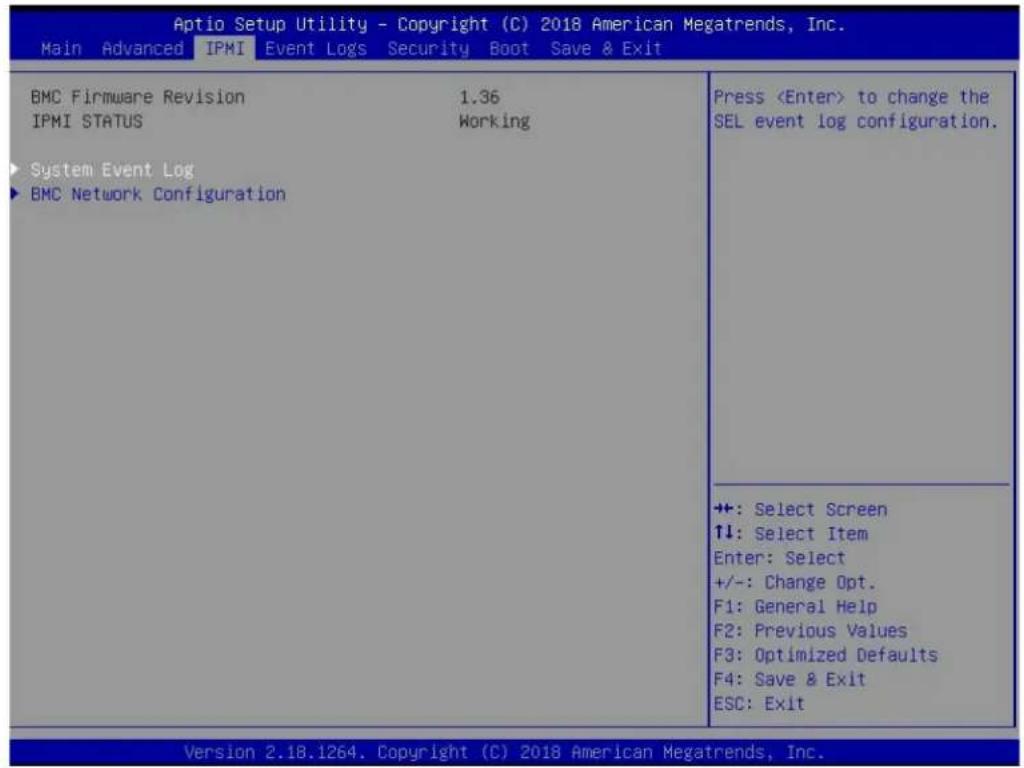
text_image
Aptio Setup Utility - Copyright (C) 2018 American Megatrends, Inc. Main Advanced IPMI Event Logs Security Boot Save & Exit BMC Firmware Revision 1.36 IPMI STATUS Working ► System Event Log ► BMC Network Configuration PressBMC Firmware Revision
This item indicates the IPMI firmware revision used in your system.
IPMI Status (Baseboard Management Controller)
This item indicates the status of the IPMI firmware installed in your system.
▶System Event Log
Enabling/Disabling Options
SEL Components
Select Enabled for all system event logging at bootup. The options are Enabled and Disabled.
Erasing Settings
Erase SEL
Select Yes, On next reset to erase all system event logs upon next system reboot. Select Yes, On every reset to erase all system event logs upon each system reboot. Select No
to keep all system event logs after each system reboot. The options are No, Yes, On next reset, and Yes, On every reset.
When SEL is Full
This feature allows the user to decide what the BIOS should do when the system event log is full. Select Erase Immediately to erase all events in the log when the system event log is full. The options are Do Nothing and Erase Immediately.
Note: After making changes on a setting, be sure to reboot the system for the changes to take effect.
▶BMC Network Configuration
BMC Network Configuration
Update IPMI LAN Configuration
Select Yes for the BIOS to implement all IP/MAC address changes at the next system boot. The options are No and Yes.
Configure IPV4 Support
This section displays static configuration features for IPV4 support.
IPMI LAN Selection
This item displays the IPMI LAN setting. The default setting is Failover.
IPMI Network Link Status
This item displays the IPMI Network Link status. The default setting is Dedicated LAN.
*If the item above is set to Yes, the following item will become available for configuration:
Configuration Address Source
This feature allows the user to select the source of the IP address for this computer. If Static is selected, you will need to know the IP address of this computer and enter it to the system manually in the field. If DHCP is selected, the BIOS will search for a DHCP (Dynamic Host Configuration Protocol) server in the network that is attached to and request the next available IP address for this computer. The options are Static and DHCP.
*If the item above is set to Static, the following items will become available for configuration:
Station IP Address
This item displays the Station IP address for this computer. This should be in decimal and in dotted quad form.
Subnet Mask
This item displays the sub-network that this computer belongs to. The value of each three-digit number separated by dots should not exceed 255.
Station MAC Address
This item displays the Station MAC address for this computer. Mac addresses are 6 two-digit hexadecimal numbers.
Gateway IP Address
This item displays the Gateway IP address for this computer. This should be in decimal and in dotted quad form (i.e., 172.31.0.1).
VLAN
This item configures the virtual LAN settings. The options are Disabled and Enable.
Configure IPV6 Support
This section displays configuration features for IPV6 support.
IPV6 Support
Use this feature to enable IPV6 support. The options are Enabled and Disabled.
Configuration Address Source
This feature allows the user to select the source of the IP address for this computer. If Static is selected, you will need to know the IP address of this computer and enter it to the system manually in the field. If DHCP is selected, the BIOS will search for a DHCP (Dynamic Host Configuration Protocol) server in the network that is attached to and request the next available IP address for this computer. The options are DHCP and Static.
\*If the item "Configuration Address Source" above is set to Static, the following items will become available for configuration:
- Station IPV6 Address
- Prefix Length
• IPV6 Router1 IP Address
7.5 Event Logs
Use this tab page to configure Event Log settings.

text_image
Aptio Setup Utility - Copyright (C) 2018 American Megatrends, Inc. Main Advanced IPMI Event Logs Security Boot Save & Exit Change SMBIOS Event Log Settings View SMBIOS Event Log Press▶Change SMBIOS Event Log Settings
This feature allows the user to configure SMBIOS Event settings.
Enabling/Disabling Options
SMBIOS Event Log
Select Enabled to enable SMBIOS (System Management BIOS) Event Logging during system boot. The options are Disabled and Enabled.
Erasing Settings
Erase Event Log
Select Yes to erase all error events in the SMBIOS (System Management BIOS) log before an event logging is initialized at bootup. The options are No, Yes, Next reset, and Yes, Every reset.
When Log is Full
Select Erase Immediately to immediately erase all errors in the SMBIOS event log when the event log is full. Select Do Nothing for the system to do nothing when the SMBIOS event log is full. The options are Do Nothing and Erase Immediately.
SMBIOS Event Log Standard Settings
Log System Boot Event
Select Enabled to log system boot events. The options are Enabled and Disabled.
MECI (Multiple Event Count Increment)
Enter the increment value for the multiple event counter. Enter a number between 1 to 255. The default setting is 1.
METW (Multiple Event Count Time Window)
This item is used to determine how long (in minutes) the multiple event counter should wait before generating a new event log. Enter a number between 0 to 99. The default setting is 60.
Note: Please reboot the system for these changes to take effect.
▶View SMBIOS Event Log
When Event Logging is on, this item allows the user to view the entries in the SMBIOS event log. The following categories are displayed:
Date/Time/Error Code/Severity
7.6 Security
Use this tab page to configure Security settings.
| Aptio Setup Utility - Copyright (C) 2018 American Megatrends, Inc. Main Advanced IPMI Event Logs Security Boot Save & Exit | |
| Administrator Password Not Installed User Password Not Installed | Set Administrator Password |
| Password Description | |
| If the Administrator's / User's password is set, then this only limits access to Setup and is asked for when entering Setup. Please set Administrator's password first in order to set User's password, if clear Administrator's password, the User's password will be cleared as well. | |
| The password length must be in the following range: | |
| Minimum length 3 Maximum length 20 | |
| Administrator Password Password Check [Setup] | +: Select Screen ↑↓: Select Item Enter: Select +/-: Change Opt. F1: General Help F2: Previous Values F3: Optimized Defaults F4: Save & Exit ESC: Exit |
| · Secure Boot | |
| Version 2.18.1264. Copyright (C) 2018 American Megatrends, Inc. | |
Administrator Password
Press Enter to create a new, or change an existing Administrator password. Note that if the Administrator Password is erased, the User Password will be cleared as well.
User Password
Press Enter to create a new, or change an existing User password.
Password Check
Select Setup for the system to check for a password at Setup. Select Always for the system to check for a password at bootup or upon entering the BIOS Setup utility. The options are Setup and Always.
▶Secure Boot
This section contains options and menus for securing your boot mode and for key management.
Secure Boot
This option allows you specify when the Platform Key (PK) is enrolled. When enabled, the System Mode is user deployed, and the CSM function is disabled. Options include Disabled and Enabled.
Secure Boot Mode
Use this item to select the secure boot mode. The options are Standard and Custom.
CSM Support
Select Enabled to support the EFI Compatibility Support Module (CSM), which provides compatibility support for traditional legacy BIOS for system boot. The options are Disabled and Enabled.
▶Key Management
This submenu allows the user to configure the following Key Management settings.
Provision Factory Defaults
Install factory default Secure Boot keys after the platform reset and while the system is in Setup mode. The options include Disabled and Enabled.
Select Yes to install all default secure keys set by the manufacturer. The options are Yes and No.
▶Enroll EFI Image
This allows the image to run in Secure Boot Mode, and enroll SHA256 hash of the binary into an Authorized Signature Database (db).
▶Secure Boot Variable
This feature allows the user to decide if all secure boot variables should be saved.
▶ Platform Key (PK)
This feature allows the user to configure the settings of the platform keys.
Update
Select Yes to load the new platform keys (PK) from the manufacturer's defaults. Select No to load the platform keys from a file. The options are Yes and No.
▶Key Exchange Keys
Update
Select Yes to load the KEK from the manufacturer's defaults. Select No to load the KEK from a file. The options are Yes and No.
Append
Select Yes to add the KEK from the manufacturer's defaults list to the existing KEK. Select No to load the KEK from a file. The options are Yes and No.
▶ Authorized Signatures
Update
Select Yes to load the database from the manufacturer's defaults. Select No to load the DB from a file. The options are Yes and No.
Append
Select Yes to add the database from the manufacturer's defaults to the existing DB. Select No to load the DB from a file. The options are Yes and No.
▶Forbidden Signatures
Update
Select Yes to load the DBX from the manufacturer's defaults. Select No to load the DBX from a file. The options are Yes and No.
Append
Select Yes to add the DBX from the manufacturer's defaults to the existing DBX. Select No to load the DBX from a file. The options are Yes and No.
▶ Authorized TimeStamps
Update
Select Yes to load the DBT from the manufacturer's defaults. Select No to load the DBT from a file. The options are Yes and No.
Append
Select Yes to add the DBT from the manufacturer's defaults list to the existing DBT. Select No to load the DBT from a file. The options are Yes and No.
▶OsRecovery Signature
This item uploads and installs an OSRecovery Signature. You may select Update for a factory default key, or select Append to get it from a file. The file formats accepted are:
1) Public Key Certificate
a. EFI Signature List
b. EFI CERT X509 (DER Encoded)
c. EFI CERT RSA2048 (bin)
d. EFI SERT SHA256 (bin)
2) EFI Time Based Authenticated Variable
When prompted, select "Yes" to load Factory Defaults or "No" to load from a file.
7.7 Boot
Use this tab page to configure Boot Settings.

text_image
Aptio Setup Utility - Copyright (C) 2018 American Megatrends, Inc. Main Advanced IPMI Event Logs Security Boot Save & Exit Boot Configuration Boot mode select [DUAL] LEGACY to EFI support [Disabled] FIXED BOOT ORDER Priorities Boot Option #1 [Network:FlexBoot v3.5.109 (PCI 11:00.0)] Boot Option #2 [CD/DVD] Boot Option #3 [USB Hard Disk] Boot Option #4 [USB CD/DVD] Boot Option #5 [USB Key] Boot Option #6 [USB Floppy] Boot Option #7 [USB Lan] Boot Option #8 [Hard Disk] Boot Option #9 [UEFI Hard Disk:Windows Boot Manager] Boot Option #10 [UEFI CD/DVD] Boot Option #11 [UEFI USB Hard Disk] Boot Option #12 [UEFI USB CD/DVD] Boot Option #13 [UEFI USB Key] Boot Option #14 [UEFI USB Floppy] Boot Option #15 [UEFI USB Lan] Select boot mode LEGACY/UEFI +: Select Screen ↑↓: Select Item Enter: Select +/-: Change Opt. F1: General Help F2: Previous Values F3: Optimized Defaults F4: Save & Exit ESC: Exit Version 2.18.1264. Copyright (C) 2018 American Megatrends, Inc.Boot Mode Select
Use this item to select the type of device that the system is going to boot from. The options are Legacy, UEFI, and Dual. The default setting is Dual.
Legacy to EFI Support
This option enables or disables the system to boot to an EFI OS after the boot failed from the legacy boot order. The options include Disabled and Enabled.
FIXED BOOT ORDER Priorities Section
This option prioritizes the order of bootable devices that the system to boot from. Press
▶ Delete Boot Option
Use this feature to remove a pre-defined boot device from which the system will boot during startup. The setting is [Select one to Delete].
▶UEFI Application Boot Priorities
This feature allows the user to specify which UEFI devices are boot devices.
- Boot Option #1
▶Hard Disk Drive BBS Priorities
This feature allows the user to specify which hard disk drive devices are boot devices.
▶NETWORK Drive BBS Priorities
This feature allows the user to specify which network drive devices are boot devices.
7.8 Save & Exit
Use this tab page to configure Save & Exit settings.
| Aptio Setup Utility - Copyright (C) 2018 American Megatrends, Inc. | |
| Main Advanced IPMI Event Logs Security Boot Save & Exit | |
| Save Options Discard Changes and Exit Save Changes and Reset Save Changes Discard Changes Default Options Restore Defaults Save as User Defaults Restore User Defaults Boot Override FlexBoot v3.5.109 (PCI 11:00.0) Windows Boot Manager (CVPF633000B02P0PGN -INTEL SSDPE2MX020T7-0) UEFI: Built-in EFI Shell Launch EFI Shell from filesystem device | Exit system setup without saving any changes. |
| +: Select Screen ↑↓: Select Item Enter: Select +/-: Change Opt. F1: General Help F2: Previous Values F3: Optimized Defaults F4: Save & Exit ESC: Exit | |
Discard Changes and Exit
Select this option to quit the BIOS Setup without making any permanent changes to the system configuration, and reboot the computer. Select Discard Changes and Exit from the Exit menu and press
Save Changes and Reset
Select this option to reset the system after saving the changes.
Save Changes
After completing the system configuration changes, select this option to save the changes you have made. This will not reset (reboot) the system.
Discard Changes
Select this option and press
Default Options
Restore Optimized Defaults
To set this feature, select Restore Defaults from the Save & Exit menu and press
Save as User Defaults
To set this feature, select Save as User Defaults from the Exit menu and press
To set this feature, select Restore User Defaults from the Exit menu and press
Boot Override Section
Listed on this section are other boot options for the system (i.e., Built-in EFI shell). Select an option and press
7.9 BIOS Update Using IPMI
If necessary, the system BIOS can be updated using IPMI. Documentation on IPMI is available at http://www.supermicro.com/products/nfo/IPMI.cfm.
- Download the BIOS file using the link on the server web page. Unzip and save it.
- Access the IPMI web interface. Enter the IP address and log in. The default username and password are ADMIN/ADMIN. (For details on IPMI, use the link above.)
- Click the Maintenance tab, then BIOS Update.

text_image
http://172.31.47.171/cgi/url_redirect.cgi?url_name=mainmenu Certificate error 172.31.47.171 Edit View Favorites Tools Help SUPERMICR Host Identification Server: 172.031.047 User: ADMIN System Server Health Configuration Remote Control Virtual Media Maintenance Miscellaneous System FRU Reading System Firmware Revision : 01.06 IP address : 172.031.047.171 Firmware Build Time : 09/05/2017 BMC MAC address : 0c:c4:7a:88:1c:0f BIOS Version : 1.0 System LAN1 MAC address : ac:1f:6b:05 BIOS Build Time : 08/24/2017 System LAN2 MAC address : ac:1f:6b:05 Redfish Version : 1.0.1 CPLD Version : 02.b4.98 Remote Console Preview Refresh Preview Image Maintenance Firmware Update Unit Reset IKVM Reset Factory Default IPMI Configuration System Event Log BIOS Update Trouble ShootingFigure 7-1. IPMI Maintenance Tab
- Browse to select the saved BIOS file and click Open.

text_image
BIO5 Upload This page displays the device is now in BIOS Update mode. Please upload your BIOS image for updating. Select BIOS image to upload C:\Users\Normami\Desktop\Browse... Upload BIOS CancelFigure 7-2. Browse and Upload Dialog
- Click the Upload BIOS button. The message appears, "Uploading image & checking BIOS information... Please wait. This may take a while."
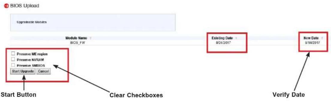
flowchart
graph TD
    A["Start Button"] --> B["Module Name: BIOS_FW"]
    B --> C{Preserve ME region}
    B --> D{Preserve NVRAM}
    B --> E{Preserve SMBIOS}
    E --> F["Start Upgrade"]
    E --> G["Cancel"]
    H["Clear Checkboxes"] --> I["Existing Date: 8/24/2017"]
    I --> J["New Date: 9/14/2017"]
    J --> K["Verify Date"]
Figure 7-3. Start Upgrade Dialog
- In the Start Upgrade dialog, make sure the three checkboxes are not checked, and verify the date of the BIOS file you uploaded before proceeding.
- Click the Start Upgrade button.
Appendix A
Standardized Warning Statements for AC Systems
About Standardized Warning Statements
The following statements are industry standard warnings, provided to warn the user of situations which have the potential for bodily injury. Should you have questions or experience difficulty, contact Supermicro's Technical Support department for assistance. Only certified technicians should attempt to install or configure components.
Read this appendix in its entirety before installing or configuring components in the Supermicro chassis.
These warnings may also be found on our website at http://www.supermicro.com/about/policies/safety_information.cfm.
Warning Definition

Warning! This warning symbol means danger. You are in a situation that could cause bodily injury. Before you work on any equipment, be aware of the hazards involved with electrical circuitry and be familiar with standard practices for preventing accidents.
警告の定義
この警告サインは危険を意味します。
Installation Instructions

Warning! Read the installation instructions before connecting the system to the power source.
設置手順書
Warning! This product relies on the building's installation for short-circuit (overcurrent) protection. Ensure that the protective device is rated not greater than: 250 V, 20 A.
サーキット・ブレーカー
Power Disconnection Warning

Warning! The system must be disconnected from all sources of power and the power cord removed from the power supply module(s) before accessing the chassis interior to install or remove system components.

text_image
CAUTION: This unit has redundant power sources. Please disconnect all the power cords before servicing.電源切断の警告
Equipment Installation

Warning! Only trained and qualified personnel should be allowed to install, replace, or service this equipment.
機器の設置
Warning! This unit is intended for installation in restricted access areas. A restricted access area can be accessed only through the use of a special tool, lock and key, or other means of security. (This warning does not apply to workstations).
アクセス制限区域
Warning! There is the danger of explosion if the battery is replaced incorrectly. Replace the battery only with the same or equivalent type recommended by the manufacturer. Dispose of used batteries according to the manufacturer's instructions
電池の取り扱い
Redundant Power Supplies

Warning! This unit might have more than one power supply connection. All connections must be removed to de-energize the unit.
冗長電源装置
Warning! Hazardous voltage or energy is present on the backplane when the system is operating. Use caution when servicing.
バックプレーンの電圧
Comply with Local and National Electrical Codes

Warning! Installation of the equipment must comply with local and national electrical codes.
地方および国の電気規格に準拠
Warning! Ultimate disposal of this product should be handled according to all national laws and regulations.
製品の廃棄
Warning! Hazardous moving parts. Keep away from moving fan blades. The fans might still be turning when you remove the fan assembly from the chassis. Keep fingers, screwdrivers, and other objects away from the openings in the fan assembly's housing.
ファン・ホットスワップの警告
Power Cable and AC Adapter

Warning! When installing the product, use the provided or designated connection cables, power cables and AC adaptors. Using any other cables and adaptors could cause a malfunction or a fire. Electrical Appliance and Material Safety Law prohibits the use of UL or CSA-certified cables (that have UL/CSA shown on the cord) for any other electrical devices than products designated by Supermicro only.
電源コードとACアダプター
System Specifications
Processors
Dual AMD EPYC 7001/7002* Series with socket SP3 Note: 7002 series drop-in support requires board revision 2.x
Chipset
System on Chip
BIOS
128Mb SPI AMI BIOS (board Rev. 1.x); 256Mb SPI AMI BIOS (board Rev. 2.x)
ACPI 6.1, SMBIOS 3.1.1, Plug-and-Play (PnP), RTC (Real Time Clock) wakeup, Riser Card Auto-Detection Support
Memory
4TB of ECC DDR4 2666 MHz speed/ 8TB of ECC DDR4 3200 MHz* speed, RDIMM/LRDIMM/3DS/NVDIMM memory in 32 slots (*Board reversion 2.x required); Size up to 128 GB
Note: See the memory section in Chapter 3 for details and our website for updates to supported memory
Storage
Twenty-four hot-swap 2.5" U.2 NVMe drive bays; Two SuperDOM (Disk on Module) ports
Motherboard
H11DSU-iN; 17" (L) x 16.8" (W) (432 mm x 427 mm)
Chassis
SC219U2TS-R1K62P-TN20; 2U Rackmount, (WxHxD) 17.2 x 3.5 x 28.5 in. (437 x 89 x 723 mm)
Weight
Net Weight: 36 lbs (16.4 kg)
Gross Weight:72 lbs (32.7 kg)
System Cooling
Four mid-chassis 8-cm fans, two CPU heatsinks, two air shrouds to direct air flow
Input/Output
LAN: Dual 25G SFP28 ports (by add-on card, AOC-2UR68-M2TS-O); one dedicated IPMI port
USB 3.0: Two ports on the rear I/O panel (USB0/1)
One type A header (Internal)
Two SATA DOM (Device on Module) power connectors
One COM port
One VGA port
Power Supply
Model: PWS-1K62A-1R; 80Plus level Titanium
Total Output Power: 1000 W/1600 W
Input:
100-127 Vac / 13 - 9 A / 50-60 Hz
200-240 Vac / 10 - 8 A / 50-60 Hz
Output +12V
Max: 83.3 A / Min: 0 A (100-127 Vac)
Max: 133 A / Min: 0 A (200-240 Vac)
12 Vsb: Max: 2.1 A / Min: 0 A
Operating Environment
Operating Temperature: 10° to 35° C (50° to 95° F)
Non-operating Temperature: -40^ to 70^ C ( -40^ to 158^ F)
Operating Relative Humidity: 8% to 90% (non-condensing)
Non-operating Relative Humidity: 5% to 95% (non-condensing)
Regulatory Compliance
FCC, ICES, CE, VCCI, RCM, NRTL, CB
Applied Directives, Standards
EMC/EMI: 2014/30/EU (EMC Directive)
FCC Part 15
ICES-003
VCCI 32-1
AS/NZS CISPR 32
EN55032
EN55035
CISPR 24
EN 61000-3-2
EN 61000-3-3
EN 61000-4-2
EN 61000-4-3
EN 61000-4-4
EN 61000-4-5
EN 61000-4-6
EN 61000-4-8
EN 61000-4-11
Green Environment:
2011/65/EU (RoHS Directive)
EC 1907/2006 (REACH)
2012/19/EU (WEEE Directive)
Product Safety: 2014/35/EU (LVD Directive)
UL/CSA 60950-1, 62368-1 (USA and Canada)
IEC/EN 60950-1, 62368-1
Perchlorate Warning
California Best Management Practices Regulations for Perchlorate Materials: This Perchlorate warning applies only to products containing CR (Manganese Dioxide) Lithium coin cells. "Perchlorate Material-special handling may apply. See www.dtsc.ca.gov/hazardouswaste/perchlorate"
Appendix C
UEFI BIOS Recovery
Warning: Do not upgrade the BIOS unless your system has a BIOS-related issue. Flashing the wrong BIOS can cause irreparable damage to the system. In no event shall Supermicro be liable for direct, indirect, special, incidental, or consequential damages arising from a BIOS update. If you need to update the BIOS, do not shut down or reset the system while the BIOS is updating. Doing so may cause a boot failure.
C.1 Overview
The Unified Extensible Firmware Interface (UEFI) provides a software-based interface between the operating system and the platform firmware in the pre-boot environment. The UEFI specification supports an architecture-independent mechanism for add-on card initialization to allow the UEFI OS loader, which is stored in the add-on card, to boot the system. The UEFI offers clean, hands-off control to a computer system at bootup.
C.2 Recovering the UEFI BIOS Image
A UEFI BIOS flash chip consists of a recovery BIOS block and a main BIOS block (a main BIOS image). The boot block contains critical BIOS codes, including memory detection and recovery codes for the user to flash a new BIOS image if the original main BIOS image is corrupted. When the system power is on, the boot block codes execute first. Once it is completed, the main BIOS code will continue with system initialization and bootup.
C.3 Recovering the BIOS Block with a USB Device
If the BIOS file is corrupted and the system is not able to boot up, this feature will allow you to recover the BIOS image using a USB-attached device. A USB flash drive or a USB CD/DVD ROM drive may be used for this purpose. Please note that a USB hard disk drive is NOT supported. Follow the procedures on the next page to recover the BIOS.
- Using a different system, copy the standard BIOS binary image file into the root directory of a USB flash drive with FAT16 or FAT32 format and rename the file to SUPER.ROM.
Note: If you cannot locate the "SUPER.ROM" file in your driver disk, visit our website at www.supermicro.com to download the correct BIOS image into a USB flash device and rename it "SUPER.ROM".
- While the system is turned off, insert the USB device that contains the new BIOS binary image (SUPER.ROM).
- Power on the system.

text_image
SUPERMOR BMC 17:18.124.16.34 DXC-System Is Going To Reset and enter Recovery Mode... 0.0- After the system is turned on, the system will enter the BIOS Recovery menu. Select "Proceed with flash update" to start the BIOS recovery process. DO NOT INTERRUPT THIS PROCESS UNTIL IT FINISHED!

text_image
Aptio Setup Utility - Copyright (C) 2010 American Megatrends, Inc. Main Advanced Event Log PSX Boot Security Exit Recovery WARNING BIOS Recovery mode has been detected Flash Update Parameters Reset Make (Created) Proceed with Flash update Select this to start flash Update +/-: Select Screen F1: Select Item Enter: Select +/-: Change Opt. F1: General Help F2: Previous Values F3: Optimized Defaults F4: Save & Exit ESC: Exit Version 2.19.2010, Copyright (C) 2010 American Megatrends, Inc. Aptio Setup Utility - Copyright (C) 2010 American Megatrends, Inc. Recovery AMERICAN System firmware is being updated. Cybeard is locked. SO NOT TURN BIG POWER OFF !!! Once firmware update is completed press any key to reboot the system Program new data Write new boot block... -2.75 +/-: Select screen F1: Select Item Enter: Select +/-: Change Opt. F1: General Help F2: Previous Values F3: Optimized Defaults F4: Save & Exit ESC: Exit Version 2.19.2010, Copyright (C) 2010 American Megatrends, Inc.- After the Boot Sector Recovery Process is complete, press any key to reboot the system.

text_image
Aptio Setup Utility - Copyright (C) 2018 American Megatrends, Inc. Recovery WARNING! System firmware is being updated. Keyboard is locked. DO NOT TURN THE POWER OFF !!! Once firmware update is completed press any key to reboot the system Flash update Flash update completed. Press any key to reset the system +: Select Screen #: Select Item Enter: Select +/-: Change Opt. F1: General Help F2: Previous Values F3: Optimized Defaults F4: Save & Exit ESC: Exit Version 2.18.1264, Copyright (C) 2018 American Megatrends, Inc.Notes:
* The BIOS recovery (SUPER.ROM) will not work if BIOS has a multi-block crash.
* If you have purchased an OOB license, you can do a BIOS flash again through BMC WebGUI or SUM. Please refer to these SUPERMICRO software-related videos:
Activate OOB license: https://www.youtube.com/watch?v=V4spX_DOV7I
SUPERMICO BIOS Update: https://www.youtube.com/watch?v=S8z6iOEHGwY
* If the BIOS flash recovery fails, contact our RMA Department to have the BIOS chip reprogrammed. This will require shipping the board to Supermicro for repair.
Submit your RMA request at https://www.supermicro.com/support/rma
Please make sure to follow all instructions when returning the motherboard.
Appendix D
IPMI Crash Dump
In the event of a processor internal error (IERR) that crashes your system, you may want to provide information to support staff. You can download a crash dump of status information using IPMI. The IPMI manual is available at https://www.supermicro.com/solutions/IPMI.cfm.
Check IPMI Error Log
- Access the IPMI web interface.
- Click the Server Health tab, then Event Log to verify an IERR error.

text_image
Host Identification Server: 172 831 040 125 User: ADMIN (Administrator) System Server Health Configuration Remote Control Virtual Media Maintenance Miscellaneous Help Server Health Sensor Readings Event Log Event Log For more special event log settings, please click here. This page displays events from the system's event log. You can choose a category from the pull-down box to filter the events and also sort them by clicking on a column header. Clear Event Log Save Select an event log category: All Events Event ID Time Stamp Sensor Name Sensor Type Description 1 2017/10/19 15:38:37 Processor IERR - Assertion 2 2017/10/19 15:50:20 Processor IERR - AssertionFigure D-1. IPMI Event Log
In the event of an IERR, the BMC executes a crash dump. You must download the crash dump and save it.
Downloading the Crash Dump File
- In the IPMI interface, click the Miscellaneous tab, then the Trouble Shooting option.
- Click the Dump button and wait five minutes for the file to be created. (No confirmation message will appear.)
- Click the Download button and a Save As dialog appears.
- Save the zipped dump file, noting the name and location.
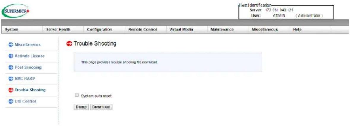
text_image
SUPERMICRO Host Identification Server: 172.031.040.125 User: ADMIN (Administrator) System Server Health Configuration Remote Control Virtual Media Maintenance Miscellaneous Help Miscellaneous Activate License Post Snooping SMC RAKP Trouble Shooting UID Control Trouble Shooting This page provides trouble shooting file download System auto reset Dump DownloadFigure D-2. IPMI Crash Dump Download
Note: The System auto reset check box dictates behavior after an IERR. If checked, the system will restart automatically, and the dump file will be erased. If not, the system remains in a failed state. Do not check this box until after the dump file has been sent to Support.